WO2014196653A1 - 信号制御装置 - Google Patents
信号制御装置 Download PDFInfo
- Publication number
- WO2014196653A1 WO2014196653A1 PCT/JP2014/065259 JP2014065259W WO2014196653A1 WO 2014196653 A1 WO2014196653 A1 WO 2014196653A1 JP 2014065259 W JP2014065259 W JP 2014065259W WO 2014196653 A1 WO2014196653 A1 WO 2014196653A1
- Authority
- WO
- WIPO (PCT)
- Prior art keywords
- delay
- signal
- peak
- unit
- waveform
- Prior art date
- Legal status (The legal status is an assumption and is not a legal conclusion. Google has not performed a legal analysis and makes no representation as to the accuracy of the status listed.)
- Ceased
Links
Images






Classifications
-
- H—ELECTRICITY
- H04—ELECTRIC COMMUNICATION TECHNIQUE
- H04S—STEREOPHONIC SYSTEMS
- H04S7/00—Indicating arrangements; Control arrangements, e.g. balance control
- H04S7/30—Control circuits for electronic adaptation of the sound field
- H04S7/305—Electronic adaptation of stereophonic audio signals to reverberation of the listening space
-
- G—PHYSICS
- G10—MUSICAL INSTRUMENTS; ACOUSTICS
- G10K—SOUND-PRODUCING DEVICES; METHODS OR DEVICES FOR PROTECTING AGAINST, OR FOR DAMPING, NOISE OR OTHER ACOUSTIC WAVES IN GENERAL; ACOUSTICS NOT OTHERWISE PROVIDED FOR
- G10K11/00—Methods or devices for transmitting, conducting or directing sound in general; Methods or devices for protecting against, or for damping, noise or other acoustic waves in general
- G10K11/18—Methods or devices for transmitting, conducting or directing sound
- G10K11/26—Sound-focusing or directing, e.g. scanning
- G10K11/34—Sound-focusing or directing, e.g. scanning using electrical steering of transducer arrays, e.g. beam steering
- G10K11/341—Circuits therefor
- G10K11/346—Circuits therefor using phase variation
-
- H—ELECTRICITY
- H04—ELECTRIC COMMUNICATION TECHNIQUE
- H04R—LOUDSPEAKERS, MICROPHONES, GRAMOPHONE PICK-UPS OR LIKE ACOUSTIC ELECTROMECHANICAL TRANSDUCERS; ELECTRIC HEARING AIDS; PUBLIC ADDRESS SYSTEMS
- H04R3/00—Circuits for transducers
- H04R3/12—Circuits for transducers for distributing signals to two or more loudspeakers
-
- H—ELECTRICITY
- H04—ELECTRIC COMMUNICATION TECHNIQUE
- H04R—LOUDSPEAKERS, MICROPHONES, GRAMOPHONE PICK-UPS OR LIKE ACOUSTIC ELECTROMECHANICAL TRANSDUCERS; ELECTRIC HEARING AIDS; PUBLIC ADDRESS SYSTEMS
- H04R2217/00—Details of magnetostrictive, piezoelectric, or electrostrictive transducers covered by H04R15/00 or H04R17/00 but not provided for in any of their subgroups
- H04R2217/03—Parametric transducers where sound is generated or captured by the acoustic demodulation of amplitude modulated ultrasonic waves
-
- H—ELECTRICITY
- H04—ELECTRIC COMMUNICATION TECHNIQUE
- H04S—STEREOPHONIC SYSTEMS
- H04S2420/00—Techniques used stereophonic systems covered by H04S but not provided for in its groups
- H04S2420/03—Application of parametric coding in stereophonic audio systems
Definitions
- the present invention relates to a signal control device that performs phase control of a high-frequency sound signal.
- Ultrasonic speakers are used as a means to transmit sound to a specific area with very strong directivity.
- the ultrasonic speaker can be heard as a sound by converting the energy transmitted by the ultrasonic wave into an audible sound in the air by nonlinear characteristics.
- a large-scale mechanism such as mechanically tilting the sound wave generation surface is required.
- an AD converter samples a modulation signal for amplitude-modulating an ultrasonic signal at a predetermined sampling frequency, sequentially generates a sample of the modulation signal, and the generated modulation signal
- the sample is stored in the storage unit, the reading unit reads out a plurality of samples having a predetermined time interval from the samples of the modulation signal, the ultrasonic signal oscillator oscillates the ultrasonic signal, Amplitude modulator modulates the ultrasonic signal using each of the read samples and outputs a plurality of modulated signals, and the plurality of electroacoustic transducers are driven by the plurality of modulated signals, respectively. It is what is done.
- the sample generation unit sequentially generates a sample of a modulated signal in which an ultrasonic signal is amplitude-modulated using a modulation signal, and the generated sample of the modulated signal is stored in a storage unit.
- the stored and read-out unit reads a plurality of samples having a predetermined time interval from the sample of the modulated signal from the storage unit, and the plurality of electroacoustic transducers are driven by the plurality of samples, respectively. is there.
- Patent Documents 1 and 2 are both techniques for performing phase control. However, it is necessary to perform complicated calculations using temporal elements, and the processing becomes complicated. In addition, when the sound speed c is used for the calculation, the sound speed c varies depending on the temperature. Therefore, if the sound speed c is used as a fixed value, an accurate calculation cannot be performed due to a temperature change. Even if it is not a fixed value, there is a problem that processing for specifying the sound velocity c corresponding to the temperature at that time is required, and the processing becomes complicated.
- the present invention provides a signal control device capable of performing phase control with high accuracy with a simple configuration and processing without being affected by the external environment.
- a signal control apparatus includes a first delay unit that inputs a modulation signal corresponding to a positive component in an input signal, and a second delay unit that inputs a modulation signal corresponding to a negative component in the input signal.
- a transducer that inputs a signal output from a delay unit of each system and outputs each signal as an ultrasonic wave, a detecting unit that detects an ultrasonic wave output from each system, and the detection Based on the waveform characteristics detected by the waveform characteristics detecting means, the waveform characteristics detecting means for detecting the waveform characteristics of the positive sound wave and the negative sound waves, integrating the ultrasonic waves for each system detected by the means,
- the delay of the first system or the delay of the second system is so reduced that the phase difference between the signal output from the first system of delay and the signal output from the second system of delay is reduced.
- the vessel in which and a delay adjusting means for inputting the delay amount of information corresponding to the phase difference.
- the signal control device As described above, in the signal control device according to the present invention, two delay devices are prepared, and a modulation signal corresponding to the positive component of the input signal is input to one side and a modulation signal corresponding to the negative component of the input signal is input to the other side.
- the waveform characteristic detecting unit detects a peak in the positive sound wave and a peak in the negative sound wave
- the delay adjusting unit detects the peak in the positive sound wave and the negative sound wave.
- the waveform characteristic detection unit detects the positive peak and the negative peak, respectively, and the delay adjustment unit adds the respective peaks, and the addition result is obtained. Since the delay amount information is input to the delay unit according to the sign of the signal, an effect is obtained that an appropriate delay amount to be fed back can be calculated with a simplified configuration and simple processing. That is, high-performance signal control can be realized at a reduced cost.
- the waveform characteristic detecting unit detects a peak in the positive sound wave and a peak in the negative sound wave
- the delay adjusting unit detects the peak component value in the positive sound wave and the peak
- a ratio with a peak component value in a negative sound wave is calculated, and information on the delay amount corresponding to the ratio is input to the first-system delay device or the second-system delay device.
- the waveform characteristic detection unit detects the positive peak and the negative peak
- the delay adjustment unit detects the positive peak component value and the negative peak component value.
- the delay amount information corresponding to the proportion is input to the delay unit, so that it is possible to calculate an appropriate delay amount to be fed back with a simplified configuration and simple processing. Play.
- the waveform characteristic detection means detects a duty ratio
- the delay adjustment means sends the delay amount information corresponding to the duty ratio to the delay device of the first system or the first This is input to two delay devices.
- the waveform characteristic detecting means detects the duty ratio, and inputs the delay amount information corresponding to the duty ratio to the delay device. It is possible to calculate an appropriate delay amount to which feedback is applied by simple processing.
- the signal control device includes selection means for allocating a signal to the first-system delay device or the second-system delay device in synchronization with the zero-cross signal of the input signal.
- signals are allocated to the first-system delay device or the second-system delay device in synchronization with the zero-cross signal of the input signal. There is an effect that the signal can be input accurately.
- the signal control apparatus electrically controls the direction of the direction of the ultrasonic speaker by controlling the phase, and is used for external environments (for example, reflection, interference, change in sound speed due to temperature, etc.). Without being affected, accurate direction control is performed at a low cost with a simple configuration.
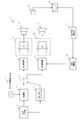
- FIG. 1 is a block diagram showing a configuration of a signal control apparatus according to the present embodiment.
- the signal control apparatus according to the present embodiment has an integral configuration with a pair of ultrasonic speakers (consisting of two transducers), and each speaker has a common superstructure from a plurality of arranged elements. A sound wave signal is output.
- the signal control device 1 includes a signal input unit 2 that inputs an arbitrary input signal, a modulation unit 5 that modulates the input signal with a signal from a carrier oscillator (for example, 30 kHz), a zero-cross comparator 3 that detects a zero-cross of the input signal, A switching unit 6 that performs switching in response to detection by the zero cross comparator 3, a first delay unit 7 that controls the phase of the positive component of the input signal, and a second delay unit 8 that controls the phase of the negative component of the input signal, From a plurality of amplifiers 9 and 10 that amplify the signals output from the delay devices, transducers 11 and 12 that are driven by the signals amplified by the amplifiers 9 and 10 and output ultrasonic waves, and the transducers 11 and 12 A microphone 13 that integrates and detects the output ultrasonic wave as an audible sound wave signal, a microphone amplifier 14 that amplifies the detected sound wave signal, and a detected sound A waveform characteristic detector 15 for detecting a waveform characteristic of a
- the input signal input to the signal input unit 2 is modulated by the modulation unit 5.
- the modulation processing by the modulation unit 5 may be any modulation such as AM modulation, FM modulation, SSB modulation, DSB modulation and the like.
- the input signal is input to the zero cross comparator 3, where the zero cross of the input signal is detected (see FIG. 2).
- the switching unit 6 performs switching in synchronization with the detected zero cross, the modulation signal corresponding to the positive component of the input signal is input to the first delay device 7, and the modulation signal corresponding to the negative component of the input signal is the second delay. Is input to the device 8.
- FIG. 3 is a diagram showing a modulation signal input to each delay unit.
- the input signal is FM-modulated by the modulation unit 5.
- 3A is an input signal
- FIG. 3B is a modulation signal
- FIG. 3C is a positive component modulation signal input to the first delay device 7
- FIG. 3D is a second delay device 8. This is a negative component modulation signal input to.
- switching is performed in synchronization with the detected zero cross, so that the first delay device 7 has a positive component modulation signal and the second delay device 8 has a negative signal.
- a component modulation signal is input.
- the signals input to the respective delay devices are input to the transducers 11 and 12 via the amplifiers 9 and 10 and output as ultrasonic waves.
- the ultrasonic waves output from the transducers 11 and 12 are detected by the microphone 13, demodulated, and integrated into one waveform.
- the microphone 13 cannot distinguish between the signal waveform output from the transducer 11 and the signal waveform output from the transducer 12, each phase cannot normally be detected, and the position of the microphone 13 depends on the position of the microphone 13. A signal distortion corresponding to the phase difference is detected.
- FIG. 4 is a diagram showing a positional relationship between the phase difference and the microphone
- FIG. 5 is a diagram schematically showing an integrated signal waveform of each speaker immediately before detection by the microphone 13 (before demodulation)
- FIG. It is a figure which shows the integrated signal waveform immediately after being detected with the microphone 13 (after demodulation).
- the signal waveform in FIG. 6B shows a state in which the DC component is removed, and a peak appears as a negative component. That is, if the phase of the signal output from the transducer 11 and the signal output from the transducer 12 are deviated as described above, it cannot be recognized as a sound wave of an accurate input signal.
- the detected waveform changes from the state shown in FIG. 6A to the state shown in FIG. 6B or FIG. 6C according to the position of the microphone 13.
- the delay amount of the delay device either the first delay device 7 or the second delay device 8 or both
- the phase shift can be eliminated and aligned.
- the signal waveform in FIG. 5 is a waveform schematically shown for explanation, and is not a waveform actually detected by the microphone 13.
- FIG. 7 is a block diagram illustrating the configuration of the waveform characteristic detection unit according to the present embodiment
- FIG. 8 is a block diagram illustrating the configuration of the delay adjustment unit according to the present embodiment.
- a waveform characteristic detection unit 15 detects a positive peak from a signal waveform detected by the microphone 13 (the signal waveform shown in FIG. 6), and detects a negative peak—a peak detection.
- Unit 17. The delay amount adjusted by the delay adjustment unit 18 is calculated using each peak detected here.
- the delay unit in this case, the second delay unit 8 is set so that the negative peak is small and the positive peak is large.
- the second delay unit is set so that the negative peak is large and the positive peak is small.
- a delay amount of 8 is calculated.
- the calculated delay amount is input to the second delay unit 8 to adjust the delay amount. Accurate direction control is performed by adjusting until the ratio of the positive peak and the negative peak becomes 1: 1 as shown in FIG. 6A, that is, the coherency approaches 0. Is possible.
- the peak of the composite waveform detected by the microphone 13 is performed without performing complicated processing such as detecting the phase of the ultrasonic signals output from the transducers 11 and 12 in time relation and analyzing them in detail. It is possible to easily and accurately control the phase only by this ratio.
- the delay adjustment unit 18 adds a peak value detected by the + peak detection unit 16 and a peak value detected by the ⁇ peak detection unit 17, and extracts a low-frequency component from the added signal.
- the low-pass filter 52 that detects the phase
- the zero-cross comparator 53 that detects the zero cross of the detected waveform
- the up / down that counts according to the positive or negative value in synchronization with the detected zero cross and the sampling clock.
- a down counter 54 is a down counter 54.
- the up / down counter 54 counts down, and the second delay device is counted in accordance with the countdown.
- the delay amount of 8 is adjusted late.
- a positive value is detected by adding the respective peak values, and the up / down counter 54 counts up. The delay amount of the two delay unit 8 is adjusted quickly.
- the delay amount of the second delay unit 8 When adjusting the delay amount of the second delay unit 8 as described above, it is difficult to quickly adjust the delay amount of the second delay unit 8 if the delay amount of the first delay unit 7 is zero. It becomes. Therefore, by delaying the first delay device 7 by a predetermined delay amount (for example, 100 ms), the delay amount of the second delay device 8 is adjusted (for example, 70 ms), and the first delay device 7 It becomes possible to set relatively faster.
- a predetermined delay amount for example, 100 ms
- the signal control apparatus according to the present embodiment will be described with reference to FIGS. In the present embodiment, the same description as in the first embodiment is omitted.
- the signal control apparatus according to the present embodiment will specifically describe processing when the type of modulation is not particularly limited. In the case of the present embodiment, the same waveform as that in the first embodiment is finally obtained.
- FIG. 9 is a diagram illustrating waveforms of signals output from the transducer 11 and the transducer 12 in the signal control apparatus according to the present embodiment.
- the positive waveform indicated by the solid line indicates the waveform of the signal output from the transducer 11, and the negative waveform indicated by the long broken line indicates the waveform of the signal output from the transducer 12.
- FIG. 10A shows the waveforms (FIG. 10A) as shown in FIGS. 10A and 10B.
- FIG. 10B shows the waveform of the signal output from the transducer 12, that is, the phase is shifted.
- the waveform output from the transducer 11 is delayed as compared with the waveform output from the transducer 12.
- FIG. 10D a sharp peak appears on the plus side, the minus peak is distorted, and the value is small. This corresponds to the waveform of FIG. 6C, and a waveform similar to that obtained by FM modulation is obtained.
- the + peak detector 16 and the ⁇ peak detector 17 detect the respective peaks. To do. After the peak detection, the delay can be controlled by performing the same process as the process described above.
- the signal control apparatus according to the present embodiment calculates delay amount information from the ratio of peak values, and controls the second delay unit 8 according to the delay amount.
- the description similar to each said embodiment is abbreviate
- the delay adjustment unit 18 is configured as shown in FIG. That is, a ratio calculation unit 61 that calculates a ratio between a peak value detected by the + peak detection unit 16 and a peak value detected by the ⁇ peak detection unit 17 (absolute value of the peak value), and a delay corresponding to the calculated ratio
- a delay amount extraction unit 62 that extracts the amount information from the delay information storage unit 63.
- the delay information storage unit 63 a ratio of the peak value measured in advance according to the position of the microphone 13 and a delay amount for aligning the phase in accordance with the ratio are stored in association with each other. By calculating, the delay amount can be acquired. The acquired delay amount information is input to the second delay unit 8 and the phase is adjusted.
- a memory or a CPU can be used.
- the delay amount to be adjusted is obtained using the duty ratio of the signal waveform detected by the microphone 13. That is, the waveform characteristic detection unit 15 calculates the duty ratio of the signal waveform detected by the microphone 13 and calculates the delay amount adjusted by the delay adjustment unit 18 according to the calculated duty ratio.
- the processing of the delay adjusting unit 18 in this second method depends on the duty ratio as in the case where the delay amount by the counter is calculated from the difference between the positive peak and the negative peak as described in FIG. Counting up / down may be performed, and the delay amount of the delay unit may be adjusted according to the count.
- the duty ratio measured in advance according to the position of the microphone 13 in accordance with the corresponding delay amount information is extracted from the ratio between the plus peak and the minus peak, and accordingly,
- the delay amount of the delay unit may be adjusted based on the delay information storage unit 63 in which the delay amount for aligning the phases is stored in association with each other.
- the phase adjustment corresponding to the position of the microphone 13 can be accurately performed by any method. Also, the circuit configuration is greatly simplified, and phase adjustment with high accuracy can be achieved at low cost.
- a sine wave is input as an input signal.
- any signal can be used for signal control according to the present invention as long as it is a sound wave signal.
- a human voice is used as an input signal, it is possible to perform signal control that can achieve the same effect with the same processing as when a sine wave is used as an input signal.
- a configuration in which a user (a person who listens to sound output from an ultrasonic speaker) holds a microphone 13 (for example, a wireless microphone) and the microphone 13 also moves simultaneously with the movement of the user can be achieved.
- the directivity of the sound wave speaker can always follow the user. That is, even when the user moves, sound waves can always be transmitted only to the user.
- the positional relationship between the speaker and the microphone is limited to a two-dimensional plane (a two-dimensional plane in a direction parallel to the ground), but the speaker is arranged in a vertical direction (a direction perpendicular to the ground).
- phase control in the height direction is also possible.
- phase control can be performed three-dimensionally.
Landscapes
- Engineering & Computer Science (AREA)
- Physics & Mathematics (AREA)
- Acoustics & Sound (AREA)
- Signal Processing (AREA)
- Multimedia (AREA)
- Health & Medical Sciences (AREA)
- General Health & Medical Sciences (AREA)
- Otolaryngology (AREA)
- Circuit For Audible Band Transducer (AREA)
- Obtaining Desirable Characteristics In Audible-Bandwidth Transducers (AREA)
Abstract
外部環境の影響を受けることなく、簡単な構成及び処理で高精度に位相制御を行うことが可能な信号制御装置を提供する。 入力信号における正成分に相当する変調信号を入力する第1遅延器7と、入力信号における負成分に相当する変調信号を入力する第2遅延器8と、それぞれの系統の遅延器から出力された信号を入力し、超音波として各系統ごとに出力するトランスデューサ11,12と、当該トランスデューサ11,12から出力されたそれぞれの系統からの超音波を検知するマイク13と、検知した各系統ごとの超音波を統合し、正の音波及び負の音波の各波形特性を検出する波形特性検出部15と、検出した波形特性に基づいて、第1遅延器7から出力された信号と第2遅延器8から出力された信号との位相差が減少するように、第1遅延器7又は第2遅延器8に、位相差に応じた遅延量の情報を入力する遅延調整部18とを備える。
Description
本発明は、高周波の音信号の位相制御を行う信号制御装置に関する。
指向性が非常に強く特定のエリアに音を伝える手段として、超音波スピーカが利用されている。超音波スピーカは、超音波が伝えるエネルギーが非線形特性により空気中で可聴音に変換されることで音として聞くことができるものである。この超音波スピーカにおいて、音を伝送する方向を可変にしたい場合、音波発生面を機械的に傾けるなどの大掛かりな機構が必要となってしまう。
このような問題に関して、例えば、特許文献1、2に示す技術が開示されている。特許文献1に示す技術は、AD変換器が、超音波信号を振幅変調するための変調信号を予め定められたサンプリング周波数でサンプリングして、変調信号のサンプルを順次生成し、生成された変調信号のサンプルは記憶部に記憶され、読出部が、変調信号のサンプルの内の予め定められた時間間隔を有する複数のサンプルを記憶から読み出し、超音波信号発振器が、超音波信号を発振し、複数の振幅変調器が、読み出された複数のサンプルをそれぞれ用いて超音波信号を振幅変調して複数の被変調信号を出力し、複数の電気音響変換器が、複数の被変調信号でそれぞれ駆動されるものである。
また、特許文献2に示す技術は、サンプル生成部が、変調信号を用いて超音波信号が振幅変調された被変調信号のサンプルを順次生成し、生成された被変調信号のサンプルは記憶部に記憶され、読出部が、被変調信号のサンプルの内の予め定められた時間間隔を有する複数のサンプルを記憶部から読み出し、複数の電気音響変換器が、複数のサンプルでそれぞれ駆動されるものである。
位相制御による超音波スピーカの方向制御の場合、外部環境の壁や天井、床などによる反射の影響で十分な方向性の制御が困難となる。
特許文献1、2に示す技術は、いずれも位相制御を行う技術であるが、時間的な要素を用いた複雑な演算を行う必要があり、処理が煩雑になってしまう。また、演算に音速cを用いた場合、この音速cは温度により変動するものであるため、固定値として利用すると、温度変化により正確な演算を行うことができなくなってしまう。固定値としない場合であっても、そのときの温度に対応する音速cを特定する処理が必要となり、処理が煩雑なものになってしまうという課題を有する。
本発明は、外部環境の影響を受けることなく、簡単な構成及び処理で高精度に位相制御を行うことが可能な信号制御装置を提供する。
本発明に係る信号制御装置は、入力信号における正成分に相当する変調信号を入力する第1系統の遅延器と、入力信号における負成分に相当する変調信号を入力する第2系統の遅延器と、それぞれの系統の遅延器から出力された信号を入力し、超音波として各系統ごとに出力するトランスデューサと、前記トランスデューサから出力されたそれぞれの系統からの超音波を検知する検知手段と、前記検知手段が検知した各系統ごとの超音波を統合し、正の音波及び負の音波の各波形特性を検出する波形特性検出手段と、前記波形特性検出手段が検出した前記波形特性に基づいて、前記第1系統の遅延器から出力された信号と前記第2系統の遅延器から出力された信号との位相差が減少するように、前記第1系統の遅延器又は前記第2系統の遅延器に、前記位相差に応じた遅延量の情報を入力する遅延調整手段とを備えるものである。
このように、本発明に係る信号制御装置においては、2系統の遅延器を用意し、一方に入力信号の正成分に相当する変調信号、他方に入力信号の負成分に相当する変調信号を入力し、それぞれから出力された超音波を検知し、各超音波を統合した際の波形特性から、それぞれの位相差が減少するように遅延量の情報をフィードバックすることで、簡素化された構成で且つシンプルな処理を行うだけで、高精度に位相制御を行うことが可能になるという効果を奏する。
本発明に係る信号制御装置は、前記波形特性検出手段が、前記正の音波におけるピーク及び負の音波におけるピークをそれぞれ検出し、前記遅延調整手段が、前記正の音波におけるピークと前記負の音波におけるピークとを加算する加算手段と、加算した結果得られた前記信号の正負に応じて前記遅延量の情報を前記第1系統の遅延器又は前記第2系統の遅延器に入力する遅延量決定手段とを備えるものである。
このように、本発明に係る信号制御装置においては、波形特性検出手段が、正のピーク及び負のピークをそれぞれ検出し、遅延調整手段が、それぞれのピークを加算し、加算の結果得られた信号の正負に応じて遅延量の情報を遅延器に入力するため、簡素化された構成且つシンプルな処理でフィードバックをかける適切な遅延量を演算することができるという効果を奏する。すなわち、コストを削減して高性能な信号制御を実現することができる。
本発明に係る信号制御装置は、前記波形特性検出手段が、前記正の音波におけるピーク及び負の音波におけるピークをそれぞれ検出し、前記遅延調整手段が、前記正の音波におけるピークの成分値と前記負の音波におけるピークの成分値との割合を算出し、当該割合に応じた前記遅延量の情報を前記第1系統の遅延器又は前記第2系統の遅延器に入力するものである。
このように、本発明に係る信号制御装置においては、波形特性検出手段が、正のピーク及び負のピークをそれぞれ検出し、遅延調整手段が、正のピークの成分値と負のピークの成分値との割合を算出し、当該割合に応じた遅延量の情報を遅延器に入力するため、簡素化された構成且つシンプルな処理でフィードバックをかける適切な遅延量を演算することができるという効果を奏する。
本発明に係る信号制御装置は、前記波形特性検出手段が、デューティ比を検出し、前記遅延調整手段が、前記デューティ比に応じた前記遅延量の情報を前記第1系統の遅延器又は前記第2系統の遅延器に入力するものである。
このように、本発明に係る信号制御装置においては、波形特性検出手段が、デューティ比を検出し、デューティ比に応じた遅延量の情報を遅延器に入力するため、簡素化された構成且つシンプルな処理でフィードバックをかける適切な遅延量を演算することができるという効果を奏する。
本発明に係る信号制御装置は、入力信号のゼロクロス信号に同期して、前記第1系統の遅延器又は前記第2系統の遅延器に信号を割り振る選択手段を備えるものである。
このように、本発明に係る信号制御装置においては、入力信号のゼロクロス信号に同期して、第1系統の遅延器又は第2系統の遅延器に信号を割り振るため、それぞれの遅延器に適切な信号を正確に入力することができるという効果を奏する。
以下、本発明の実施の形態を説明する。また、本実施形態の全体を通して同じ要素には同じ符号を付けている。
(本発明の第1の実施形態)
本実施形態に係る信号制御装置について、図1ないし図8を用いて説明する。本実施形態に係る信号制御装置は、超音波スピーカの指向の方向制御を位相を制御することで電気的に行うものであり、外部環境(例えば、反射、干渉、温度による音速の変化等)の影響を受けることなく、簡単な構成で正確な方向制御を安価に行うものである。
本実施形態に係る信号制御装置について、図1ないし図8を用いて説明する。本実施形態に係る信号制御装置は、超音波スピーカの指向の方向制御を位相を制御することで電気的に行うものであり、外部環境(例えば、反射、干渉、温度による音速の変化等)の影響を受けることなく、簡単な構成で正確な方向制御を安価に行うものである。
図1は、本実施形態に係る信号制御装置の構成を示すブロック図である。本実施形態に係る信号制御装置は、1対(2個のトランスデューサからなる)の超音波スピーカと一体の構成となっており、各スピーカにおいては、配設されている複数のエレメントから共通の超音波信号が出力される。
信号制御装置1は、任意の入力信号を入力する信号入力部2と、入力信号をキャリア発振器(例えば、30kHz)の信号で変調する変調部5と、入力信号のゼロクロスを検出するゼロクロスコンパレータ3と、ゼロクロスコンパレータ3の検出に応じてスイッチングを行う切替部6と、入力信号の正成分の位相を制御する第1遅延器7と、入力信号の負成分の位相を制御する第2遅延器8と、各遅延器から出力された信号を増幅する複数のアンプ9,10と、アンプ9,10で増幅された信号により駆動されて超音波を出力するトランスデューサ11,12と、各トランスデューサ11,12から出力された超音波を可聴音の音波信号として統合して検知するマイク13と、検知した音波信号を増幅するマイクアンプ14と、検知した音波信号の信号波形における正の音波の波形特性と負の音波の波形特性を検出する波形特性検出部15と、検出された波形特性から位相を制御するための遅延量を演算し、第2遅延器に入力して位相制御を行う遅延調整部18とを備える。
本実施形態においては、分かり易くするために、図2に示すようなサイン波を入力信号とした場合について説明するが、通常の音声のような複雑な信号波形であっても、本実施形態に係る信号制御を適用可能である。
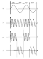
信号入力部2に入力された入力信号は、変調部5で変調される。この変調部5による変調処理は、AM変調、FM変調、SSB変調、DSB変調等のようにいずれの変調であってもよい。また、入力信号はゼロクロスコンパレータ3に入力され、そこで入力信号のゼロクロスが検出される(図2を参照)。検出されたゼロクロスに同期して切替部6がスイッチングを行い、入力信号の正成分に相当する変調信号は第1遅延器7に入力され、入力信号の負成分に相当する変調信号は第2遅延器8に入力される。
図3は、それぞれの遅延器に入力される変調信号を示す図である。ここでは、変調部5により入力信号がFM変調されたものとする。図3(A)は入力信号、図3(B)は変調信号、図3(C)は第1遅延器7に入力された正成分の変調信号、図3(D)は第2遅延器8に入力された負成分の変調信号である。図3(C)、(D)に示すように、検出されたゼロクロスに同期してスイッチングが行われることで、第1遅延器7には正成分の変調信号、第2遅延器8には負成分の変調信号が入力される。
それぞれの遅延器に入力された信号は、アンプ9,10を介してトランスデューサ11,12に入力され、超音波として出力される。各トランスデューサ11,12から出力された超音波は、マイク13で検知され、復調されて一つの波形に統合される。このとき、マイク13は、トランスデューサ11から出力された信号波形とトランスデューサ12から出力された信号波形の区別が付かないため、通常はそれぞれの位相を検知することはできず、マイク13の位置によって位相差に応じた信号の歪みが検知される。
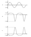
図4は、位相差とマイクとの位置関係を示す図、図5は、マイク13で検知される直前(復調前)における各スピーカの統合された信号波形を模式的に示す図、図6は、マイク13で検知された直後(復調後)の統合された信号波形を示す図である。
図4(A)に示すように、各スピーカから出力された超音波信号の位相が揃った状態でマイクに入力された場合、すなわち、第1遅延器7側のスピーカ(以下、第1系統のスピーカとする)とマイク13との距離をd1、第2遅延器8側のスピーカ(以下、第2系統のスピーカとする)とマイク13との距離をd2とすると、d1=d2の場合は、図5(A)に示すように入力信号と同様の変調された信号波形となり、復調すると図6(A)に示すように入力信号と同形のサイン波が検出される。
図4(B)に示すように、マイク13の位置関係がd1<d2の場合は、トランスデューサ11から出力された信号が強く、トランスデューサ12から出力された信号が弱くなり、各トランスデューサから出力された超音波信号の位相がずれてしまうため、図5(B)に示すような状態の変調信号となり、復調されることで図6(B)に示すような歪んだ波形として検出される。
なお、この図6(B)の信号波形は、DC成分が取り除かれた状態を示しており、負成分にするどいピークが現れている。つまり、このように、トランスデューサ11から出力された信号とトランスデューサ12から出力された信号の位相がずれていると、正確な入力信号の音波として捉えることができない。
同様に、図4(C)に示すように、マイク13の位置関係がd1>d2の場合は、トランスデューサ12から出力された信号が強く、トランスデューサ11から出力された信号が弱くなり、各トランスデューサから出力された超音波信号の位相がずれてしまうため、図5(C)に示すような状態の変調信号となり、復調されることで図6(C)に示すような歪んだ波形が検出され、図6(B)の場合と同様に、正確な入力信号の音波として捉えることができない。
すなわち、マイク13の位置に応じて、検出される波形が、図6(A)の状態から図6(B)や図6(C)の状態に変化することとなる。図4(B)及び図4(C)に示したように、位相がずれた状態の場合に、遅延器(第1遅延器7又は第2遅延器8のいずれか一方又は双方)の遅延量を調整することで、位相のずれを解消し、揃えることができる。なお、図5の信号波形は、説明のために模式的に示した波形であり、実際にマイク13で検出される波形ではない。
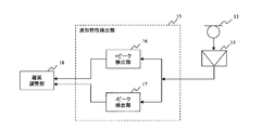
以下に、本実施形態における遅延量の調整方法について具体的に説明する。ここでは、マイク13で検知された信号波形の正のピーク及び負のピークを用いて、調整する遅延量を求めるものである。図7は、本実施形態に係る波形特性検出部の構成を示すブロック図、図8は、本実施形態に係る遅延調整部の構成を示すブロック図である。図7において、波形特性検出部15は、マイク13で検出された信号波形(図6に示す信号波形)からプラスのピークを検出する+ピーク検出部16と、マイナスのピークを検出する-ピーク検出部17とを備える。ここで検出されたそれぞれのピークを用いて遅延調整部18が調整する遅延量を算出する。
つまり、図6(B)のように、マイナスのピークが大きく、プラスのピークが小さい場合は、マイナスのピークを小さく、プラスのピークを大きくするように遅延器(ここでは、第2遅延器8)の遅延量を算出する。また、図6(C)のような場合は、逆に、マイナスのピークが小さく、プラスのピークが大きくなっているため、マイナスのピークを大きく、プラスのピークを小さくするように第2遅延器8の遅延量を算出する。算出された遅延量は、第2遅延器8に入力されて遅延量が調整される。プラスのピークとマイナスのピークとの割合が図6(A)に示すように1:1になるまで、すなわちコヒレンシが0に近づくように調整を行うことで、指向の方向制御を正確に行うことが可能となる。
こうすることで、各トランスデューサ11,12から出力される超音波信号の位相を時間関係で検出して詳細に解析するような複雑な処理を行うことなく、マイク13で検知された合成波形のピークの割合のみで簡単に且つ正確な位相制御が可能となる。
次に、図8に示す遅延調整部18の具体的な処理について説明する。図8において、遅延調整部18は、+ピーク検出部16が検出したピーク値と-ピーク検出部17が検出したピーク値とを加算する加算部51と、加算された信号から低周波成分を抽出して位相を検出するローパスフィルタ52と、検出された波形のゼロクロスを検出するゼロクロスコンパレータ53と、検出されたゼロクロス及びサンプリングクロックに同期して、正又は負の値に応じたカウントを行うアップ/ダウンカウンタ54とを備える。
つまり、図6(B)のような波形の場合は、それぞれのピーク値を加算することにより負の値が検出され、アップ/ダウンカウンタ54がカウントダウンを行い、そのカウントダウンに応じて第2遅延器8の遅延量が遅く調整される。逆に、図6(C)のような波形の場合は、それぞれのピーク値を加算することにより正の値が検出されてアップ/ダウンカウンタ54がカウントアップを行い、そのカウントアップに応じて第2遅延器8の遅延量が速く調整される。
なお、上記のように第2遅延器8の遅延量を調節する場合に、第1遅延器7の遅延量がゼロの状態だと、第2遅延器8の遅延量を速く調整することが困難となる。したがって、第1遅延器7を所定の遅延量(例えば、100ms等)で遅延させておくことで、第2遅延器8の遅延量を調整して(例えば、70ms等)、第1遅延器7より相対的に速く設定することが可能となる。
(本発明の第2の実施形態)
本実施形態に係る信号制御装置について、図9ないし図12を用いて説明する。なお、本実施形態において、前記第1の実施形態と同様の説明は省略する。本実施形態に係る信号制御装置は、特に変調の種別を限定しない場合の処理について具体的に説明する。本実施形態の場合も最終的には第1の実施形態の場合と同様の波形を得る結果となる。
本実施形態に係る信号制御装置について、図9ないし図12を用いて説明する。なお、本実施形態において、前記第1の実施形態と同様の説明は省略する。本実施形態に係る信号制御装置は、特に変調の種別を限定しない場合の処理について具体的に説明する。本実施形態の場合も最終的には第1の実施形態の場合と同様の波形を得る結果となる。
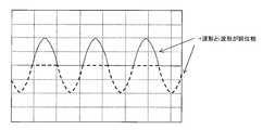
図9は、本実施形態に係る信号制御装置において、トランスデューサ11及びトランスデューサ12から出力された信号の波形を示す図である。実線で示す正の波形がトランスデューサ11から出力された信号の波形を示し、長破線で示す負の波形がトランスデューサ12から出力された信号の波形を示している。マイク13の位置が、それぞれのトランスデューサ11及びトランスデューサ12から同じ距離、すなわち、図4(A)のようなd1=d2における位置では、図9に示すようにそれぞれの波形が同位相となり、きれいなサイン波が検出される。
これに対して、マイク13の位置が図4(C)のようなd1>d2における位置では、図10(A)、(B)に示すようにそれぞれの波形(図10(A)がトランスデューサ11から出力された信号の波形、図10(B)がトランスデューサ12から出力された信号の波形)で位相差が生じ、すなわち位相がずれる。ここでは、d1の距離が長いため、トランスデューサ11から出力された波形がトランスデューサ12から出力された波形に比べて遅れている。それぞれの波形は、マイク13において図10(C)のように合成され、さらにローパスフィルタにより図10(D)のような波形で検出される。図10(D)は、プラス側に鋭いピークが現れ、マイナス側のピークが歪んで値が小さくなっている。これは、図6(C)の波形に対応しており、FM変調した場合と同様の波形が得られている。
一方、マイク13の位置が図4(B)のようなd1<d2における位置では、図11(A)、(B)に示すようにそれぞれの波形(図11(A)がトランスデューサ11から出力された信号の波形、図11(B)がトランスデューサ12から出力された信号の波形)で位相差が生じ、すなわち位相がずれる。ここでは、d1の距離が短いため、トランスデューサ11から出力された波形がトランスデューサ12から出力された波形に比べて進んでいる。それぞれの波形は、マイク13において図11(C)のように合成され、さらにローパスフィルタにより図11(D)のような波形で検出される。図11(D)に示すように、マイナス側に鋭いピークが現れ、プラス側のピークが歪んで値が小さくなっている。これは、図6(B)の波形に対応しており、FM変調した場合と同様の波形が得られている。
マイク13で得られた波形(図10(D)、図11(D))に対して、図12に示すように、+ピーク検出部16と-ピーク検出部17とが、それぞれのピークを検出する。ピーク検出後は、上述した処理と同様の処理を行うことで、遅延を制御することができる。
(本発明の第3の実施形態)
本実施形態に係る信号制御装置について、図13を用いて説明する。本実施形態に係る信号制御装置は、遅延量の情報をピーク値の割合から算出して、その遅延量に応じて第2遅延器8を制御するものである。なお、本実施形態において、前記各実施形態と同様の説明は省略する。
本実施形態に係る信号制御装置について、図13を用いて説明する。本実施形態に係る信号制御装置は、遅延量の情報をピーク値の割合から算出して、その遅延量に応じて第2遅延器8を制御するものである。なお、本実施形態において、前記各実施形態と同様の説明は省略する。
本実施形態においては、遅延調整部18を、図13のような構成とする。すなわち、+ピーク検出部16が検出したピーク値と-ピーク検出部17が検出したピーク値(ピーク値の絶対値)との割合を算出する割合算出部61と、算出された割合に対応する遅延量の情報を遅延情報記憶部63から抽出する遅延量抽出部62とを備える。遅延情報記憶部63には、マイク13の位置に応じて予め測定されたピーク値の割合と、それに応じて位相を揃えるための遅延量とが対応付けて記憶されており、ピーク値の割合を算出することで、遅延量を取得することができる構成となっている。取得した遅延量の情報は、第2遅延器8に入力され位相が調整される。情報の記憶や演算を行う場合は、例えば、メモリやCPUを用いることができる。
(その他の実施形態)
その他の実施形態について説明する。ここでは、遅延量の調整を行う第2の方法について説明する。第2の方法では、第1の実施形態の場合と異なり、マイク13で検知された信号波形のデューティ比を用いて、調整する遅延量を求める。すなわち、波形特性検出部15が、マイク13で検知された信号波形のデューティ比を算出し、算出されたデューティ比に応じて遅延調整部18が調整する遅延量を算出する。
その他の実施形態について説明する。ここでは、遅延量の調整を行う第2の方法について説明する。第2の方法では、第1の実施形態の場合と異なり、マイク13で検知された信号波形のデューティ比を用いて、調整する遅延量を求める。すなわち、波形特性検出部15が、マイク13で検知された信号波形のデューティ比を算出し、算出されたデューティ比に応じて遅延調整部18が調整する遅延量を算出する。
なお、この第2の方法における遅延調整部18の処理については、図8で説明したように、プラスピークとマイナスピークとの差分からカウンタによる遅延量を演算した場合と同様に、デューティ比に応じたカウントアップ/カウントダウンを行い、そのカウントに応じて遅延器の遅延量が調整されるようにしてもよい。
また、図13で説明したように、プラスピークとマイナスピークとの割合から対応する遅延量の情報を抽出する場合と同様に、マイク13の位置に応じて予め測定されたデューティ比と、それに応じて位相を揃えるための遅延量とが対応付けて記憶された遅延情報記憶部63に基づいて、遅延器の遅延量が調整されるようにしてもよい。
以上、各実施形態において説明したように、いずれの手法であっても、マイク13の位置に対応した位相調整を正確に行うことができる。また、回路構成も非常に簡素化され、低コストで高精度な位相調整を可能としている。
なお、上記各実施形態の説明においては、入力信号としてサイン波を入力したが、音波信号であればどのような信号であっても本発明に係る信号制御を行うことが可能である。例えば、人の音声を入力信号とした場合であっても、サイン波を入力信号とした場合と全く同じ処理で、同様の効果が得られる信号制御を行うことが可能である。
また、利用者(超音波スピーカから出力される音を聴く人)がマイク13(例えば、ワイヤレスマイク)を保持し、利用者の移動に伴ってマイク13も同時に移動する構成とすることで、超音波スピーカの指向性が常に利用者を追従することができる。つまり、利用者が移動した場合であっても、常に利用者にのみ音波を送信することができるものである。
さらに、上記の説明では、スピーカとマイクの位置関係を二次元平面(地面に対して水平方向の二次元平面)に限定しているが、スピーカを縦方向(地面に対して垂直方向)に配置することで、高さ方向の位相制御も可能となる。また、水平方向に並列する1対のスピーカと垂直方向に並列する1対のスピーカとを組み合わせることで、3次元的に位相制御を行うことが可能となる。
さらにまた、スピーカを3つ以上(直線上に配置しない)を配設し、各スピーカごとの遅延量を調整することでも3次元的に位相制御を行うことが可能となる。
1 信号制御装置
2 信号入力部
3 ゼロクロスコンパレータ
4 キャリア発振器
5 変調部
6 切替部
7 第1遅延器
8 第2遅延器
9,10 アンプ
11,12 トランスデューサ
13 マイク
14 マイクアンプ
16 +ピーク検出部
17 -ピーク検出部
18 遅延調整部
51 加算器
52 ローパスフィルタ
53 ゼロクロスコンパレータ
54 カウンタ
61 割合算出部
62 遅延量抽出部
63 遅延情報記憶部
2 信号入力部
3 ゼロクロスコンパレータ
4 キャリア発振器
5 変調部
6 切替部
7 第1遅延器
8 第2遅延器
9,10 アンプ
11,12 トランスデューサ
13 マイク
14 マイクアンプ
16 +ピーク検出部
17 -ピーク検出部
18 遅延調整部
51 加算器
52 ローパスフィルタ
53 ゼロクロスコンパレータ
54 カウンタ
61 割合算出部
62 遅延量抽出部
63 遅延情報記憶部
Claims (5)
- 入力信号における正成分に相当する変調信号を入力する第1系統の遅延器と、
入力信号における負成分に相当する変調信号を入力する第2系統の遅延器と、
それぞれの系統の遅延器から出力された信号を入力し、超音波として各系統ごとに出力するトランスデューサと、
前記トランスデューサから出力されたそれぞれの系統からの超音波を検知する検知手段と、
前記検知手段が検知した各系統ごとの超音波を統合し、正の音波及び負の音波の各波形特性を検出する波形特性検出手段と、
前記波形特性検出手段が検出した前記波形特性に基づいて、前記第1系統の遅延器から出力された信号と前記第2系統の遅延器から出力された信号との位相差が減少するように、前記第1系統の遅延器又は前記第2系統の遅延器に、前記位相差に応じた遅延量の情報を入力する遅延調整手段とを備えることを特徴とする信号制御装置。 - 請求項1に記載の信号制御装置において、
前記波形特性検出手段が、前記正の音波におけるピーク及び負の音波におけるピークをそれぞれ検出し、
前記遅延調整手段が、
前記正の音波におけるピークと前記負の音波におけるピークとを加算する加算手段と、
加算した結果得られた前記信号の正負に応じて前記遅延量の情報を前記第1系統の遅延器又は前記第2系統の遅延器に入力する遅延量決定手段とを備えることを特徴とする信号制御装置。 - 請求項1に記載の信号制御装置において、
前記波形特性検出手段が、前記正の音波におけるピーク及び負の音波におけるピークをそれぞれ検出し、
前記遅延調整手段が、前記正の音波におけるピークの成分値と前記負の音波におけるピークの成分値との割合を算出し、当該割合に応じた前記遅延量の情報を前記第1系統の遅延器又は前記第2系統の遅延器に入力することを特徴とする信号制御装置。 - 請求項1に記載の信号制御装置において、
前記波形特性検出手段が、デューティ比を検出し、
前記遅延調整手段が、前記デューティ比に応じた前記遅延量の情報を前記第1系統の遅延器又は前記第2系統の遅延器に入力することを特徴とする信号制御装置。 - 請求項1ないし4のいずれかに記載の信号制御装置において、
前記入力信号のゼロクロス信号に同期して、前記第1系統の遅延器又は前記第2系統の遅延器に信号を割り振る選択手段を備えることを特徴とする信号制御装置。
Priority Applications (2)
| Application Number | Priority Date | Filing Date | Title |
|---|---|---|---|
| JP2015521515A JP6164592B2 (ja) | 2013-06-07 | 2014-06-09 | 信号制御装置 |
| US14/959,797 US9949055B2 (en) | 2013-06-07 | 2015-12-04 | Signal control apparatus |
Applications Claiming Priority (2)
| Application Number | Priority Date | Filing Date | Title |
|---|---|---|---|
| JP2013-120953 | 2013-06-07 | ||
| JP2013120953 | 2013-06-07 |
Related Child Applications (1)
| Application Number | Title | Priority Date | Filing Date |
|---|---|---|---|
| US14/959,797 Continuation US9949055B2 (en) | 2013-06-07 | 2015-12-04 | Signal control apparatus |
Publications (1)
| Publication Number | Publication Date |
|---|---|
| WO2014196653A1 true WO2014196653A1 (ja) | 2014-12-11 |
Family
ID=52008278
Family Applications (1)
| Application Number | Title | Priority Date | Filing Date |
|---|---|---|---|
| PCT/JP2014/065259 Ceased WO2014196653A1 (ja) | 2013-06-07 | 2014-06-09 | 信号制御装置 |
Country Status (3)
| Country | Link |
|---|---|
| US (1) | US9949055B2 (ja) |
| JP (1) | JP6164592B2 (ja) |
| WO (1) | WO2014196653A1 (ja) |
Cited By (3)
| Publication number | Priority date | Publication date | Assignee | Title |
|---|---|---|---|---|
| CN113905305A (zh) * | 2021-08-02 | 2022-01-07 | 钰太芯微电子科技(上海)有限公司 | 一种指向可变换的mems麦克风及电子设备 |
| CN115104322A (zh) * | 2020-01-08 | 2022-09-23 | 元平台技术有限公司 | 头戴式装置偶极子音频组件 |
| CN116458170A (zh) * | 2020-11-18 | 2023-07-18 | 元平台技术有限公司 | 具有长杆偶极子的音频组件 |
Families Citing this family (4)
| Publication number | Priority date | Publication date | Assignee | Title |
|---|---|---|---|---|
| CN104066036A (zh) * | 2014-06-19 | 2014-09-24 | 华为技术有限公司 | 拾音装置及拾音方法 |
| US9736595B2 (en) * | 2015-06-23 | 2017-08-15 | Dsp Group Ltd. | Two port speaker acoustic modulator |
| US10484784B1 (en) * | 2018-10-19 | 2019-11-19 | xMEMS Labs, Inc. | Sound producing apparatus |
| US10771893B1 (en) * | 2019-10-10 | 2020-09-08 | xMEMS Labs, Inc. | Sound producing apparatus |
Citations (2)
| Publication number | Priority date | Publication date | Assignee | Title |
|---|---|---|---|---|
| JP2003143686A (ja) * | 2001-11-06 | 2003-05-16 | Nippon Telegr & Teleph Corp <Ntt> | 音場制御方法・音場制御装置 |
| JP2009260690A (ja) * | 2008-04-17 | 2009-11-05 | Nippon Telegr & Teleph Corp <Ntt> | 音響再生装置及び音響再生方法 |
Family Cites Families (12)
| Publication number | Priority date | Publication date | Assignee | Title |
|---|---|---|---|---|
| US4213085A (en) * | 1978-08-28 | 1980-07-15 | Ramer Daniel J | Phase inversion test device |
| US6753729B2 (en) * | 2000-01-06 | 2004-06-22 | Mitek Corporation | Self-oscillating variable frequency closed loop Class D amplifier |
| JP4371268B2 (ja) * | 2003-12-18 | 2009-11-25 | シチズンホールディングス株式会社 | 指向性スピーカーの駆動方法および指向性スピーカー |
| KR100728043B1 (ko) * | 2006-08-04 | 2007-06-14 | 삼성전자주식회사 | 청취자에게 동상의 음향을 제공하는 방법 및 장치 |
| JP4950936B2 (ja) | 2008-04-17 | 2012-06-13 | 日本電信電話株式会社 | 音響再生装置及び音響再生方法 |
| US8132352B2 (en) * | 2008-08-01 | 2012-03-13 | Lippard Karl C | Handgun system |
| US9005016B2 (en) * | 2008-10-24 | 2015-04-14 | Lee Amaitis | Wagering on event outcomes during the event |
| US9357247B2 (en) * | 2008-11-24 | 2016-05-31 | Time Warner Cable Enterprises Llc | Apparatus and methods for content delivery and message exchange across multiple content delivery networks |
| US9906838B2 (en) * | 2010-07-12 | 2018-02-27 | Time Warner Cable Enterprises Llc | Apparatus and methods for content delivery and message exchange across multiple content delivery networks |
| EP2671221B1 (en) * | 2011-02-03 | 2017-02-01 | Telefonaktiebolaget LM Ericsson (publ) | Determining the inter-channel time difference of a multi-channel audio signal |
| JP5963453B2 (ja) * | 2011-03-15 | 2016-08-03 | 株式会社荏原製作所 | 検査装置 |
| JP6044269B2 (ja) * | 2011-11-04 | 2016-12-14 | ヤマハ株式会社 | 自励発振型d級アンプおよび自励発振型d級アンプの自励発振周波数制御方法 |
-
2014
- 2014-06-09 JP JP2015521515A patent/JP6164592B2/ja not_active Expired - Fee Related
- 2014-06-09 WO PCT/JP2014/065259 patent/WO2014196653A1/ja not_active Ceased
-
2015
- 2015-12-04 US US14/959,797 patent/US9949055B2/en not_active Expired - Fee Related
Patent Citations (2)
| Publication number | Priority date | Publication date | Assignee | Title |
|---|---|---|---|---|
| JP2003143686A (ja) * | 2001-11-06 | 2003-05-16 | Nippon Telegr & Teleph Corp <Ntt> | 音場制御方法・音場制御装置 |
| JP2009260690A (ja) * | 2008-04-17 | 2009-11-05 | Nippon Telegr & Teleph Corp <Ntt> | 音響再生装置及び音響再生方法 |
Cited By (3)
| Publication number | Priority date | Publication date | Assignee | Title |
|---|---|---|---|---|
| CN115104322A (zh) * | 2020-01-08 | 2022-09-23 | 元平台技术有限公司 | 头戴式装置偶极子音频组件 |
| CN116458170A (zh) * | 2020-11-18 | 2023-07-18 | 元平台技术有限公司 | 具有长杆偶极子的音频组件 |
| CN113905305A (zh) * | 2021-08-02 | 2022-01-07 | 钰太芯微电子科技(上海)有限公司 | 一种指向可变换的mems麦克风及电子设备 |
Also Published As
| Publication number | Publication date |
|---|---|
| US9949055B2 (en) | 2018-04-17 |
| JP6164592B2 (ja) | 2017-07-19 |
| US20160088418A1 (en) | 2016-03-24 |
| JPWO2014196653A1 (ja) | 2017-02-23 |
Similar Documents
| Publication | Publication Date | Title |
|---|---|---|
| JP6164592B2 (ja) | 信号制御装置 | |
| US10219094B2 (en) | Acoustic detection of audio sources to facilitate reproduction of spatial audio spaces | |
| KR101349268B1 (ko) | 마이크로폰 어레이를 이용한 음원 거리 측정 장치 | |
| US20130158411A1 (en) | Ultrasound diagnostic apparatus and control method for ultrasound diagnostic apparatus | |
| NL8300671A (nl) | Automatisch egalisatiesysteem met dtf of fft. | |
| CN105718064A (zh) | 基于超声波的手势识别系统与方法 | |
| US20230071703A1 (en) | Intelligent device, intelligent speaker, and method and system for controlling the same | |
| US10154345B2 (en) | Surround sound recording for mobile devices | |
| JP2006081117A (ja) | 超指向性スピーカシステム | |
| CN109709559B (zh) | 超声传感器及其控制方法 | |
| JP6815786B2 (ja) | 超音波変位計測装置及び超音波変位計測方法 | |
| JP2009171587A (ja) | ウーハーの音声生成ユニットの変位量および動きを検出する方法および装置 | |
| JP4960838B2 (ja) | 距離測定装置、距離測定方法、距離測定プログラム、および記録媒体 | |
| WO2012148390A1 (en) | Measurement of 3d coordinates of transmitter | |
| EP3182734B1 (en) | Method for using a mobile device equipped with at least two microphones for determining the direction of loudspeakers in a setup of a surround sound system | |
| US7672809B2 (en) | Object tracker | |
| JPH0161190B2 (ja) | ||
| JP2017223596A (ja) | 方位測定システム | |
| Mikulka et al. | Parametric array as a source of audible signal | |
| JP2017143459A (ja) | 伝搬遅延特性の測定方法および装置 | |
| KR101597918B1 (ko) | 메모리 배열 뱅크를 이용한 파라메트릭 배열용 빔 형성 및 조향 장치 | |
| CN114355291B (zh) | 基于微系统技术的声源定位设备、方法、装置及系统 | |
| SU611227A1 (ru) | Устройство дл считывани графической информации | |
| Yang et al. | CRT-IFPD: Chinese Remainder Theorem-Based Interfrequency Phase Difference for Absolute Acoustic Ranging Without Time Synchronization | |
| CN108802686A (zh) | 基于参考点最大距离的声音定位可信度实施方法 |
Legal Events
| Date | Code | Title | Description |
|---|---|---|---|
| 121 | Ep: the epo has been informed by wipo that ep was designated in this application |
Ref document number: 14806964 Country of ref document: EP Kind code of ref document: A1 |
|
| ENP | Entry into the national phase |
Ref document number: 2015521515 Country of ref document: JP Kind code of ref document: A |
|
| NENP | Non-entry into the national phase |
Ref country code: DE |
|
| 122 | Ep: pct application non-entry in european phase |
Ref document number: 14806964 Country of ref document: EP Kind code of ref document: A1 |