WO2014196511A1 - 画像入力装置 - Google Patents
画像入力装置 Download PDFInfo
- Publication number
- WO2014196511A1 WO2014196511A1 PCT/JP2014/064679 JP2014064679W WO2014196511A1 WO 2014196511 A1 WO2014196511 A1 WO 2014196511A1 JP 2014064679 W JP2014064679 W JP 2014064679W WO 2014196511 A1 WO2014196511 A1 WO 2014196511A1
- Authority
- WO
- WIPO (PCT)
- Prior art keywords
- optical system
- eye optical
- compound
- image
- regions
- Prior art date
- Legal status (The legal status is an assumption and is not a legal conclusion. Google has not performed a legal analysis and makes no representation as to the accuracy of the status listed.)
- Ceased
Links
Images






Classifications
-
- G—PHYSICS
- G03—PHOTOGRAPHY; CINEMATOGRAPHY; ANALOGOUS TECHNIQUES USING WAVES OTHER THAN OPTICAL WAVES; ELECTROGRAPHY; HOLOGRAPHY
- G03B—APPARATUS OR ARRANGEMENTS FOR TAKING PHOTOGRAPHS OR FOR PROJECTING OR VIEWING THEM; APPARATUS OR ARRANGEMENTS EMPLOYING ANALOGOUS TECHNIQUES USING WAVES OTHER THAN OPTICAL WAVES; ACCESSORIES THEREFOR
- G03B13/00—Viewfinders; Focusing aids for cameras; Means for focusing for cameras; Autofocus systems for cameras
- G03B13/32—Means for focusing
- G03B13/34—Power focusing
- G03B13/36—Autofocus systems
-
- G—PHYSICS
- G02—OPTICS
- G02B—OPTICAL ELEMENTS, SYSTEMS OR APPARATUS
- G02B3/00—Simple or compound lenses
- G02B3/0006—Arrays
-
- G—PHYSICS
- G02—OPTICS
- G02B—OPTICAL ELEMENTS, SYSTEMS OR APPARATUS
- G02B7/00—Mountings, adjusting means, or light-tight connections, for optical elements
- G02B7/28—Systems for automatic generation of focusing signals
- G02B7/36—Systems for automatic generation of focusing signals using image sharpness techniques, e.g. image processing techniques for generating autofocus signals
- G02B7/38—Systems for automatic generation of focusing signals using image sharpness techniques, e.g. image processing techniques for generating autofocus signals measured at different points on the optical axis, e.g. focussing on two or more planes and comparing image data
-
- G—PHYSICS
- G02—OPTICS
- G02B—OPTICAL ELEMENTS, SYSTEMS OR APPARATUS
- G02B27/00—Optical systems or apparatus not provided for by any of the groups G02B1/00 - G02B26/00, G02B30/00
- G02B27/10—Beam splitting or combining systems
- G02B27/1066—Beam splitting or combining systems for enhancing image performance, like resolution, pixel numbers, dual magnifications or dynamic range, by tiling, slicing or overlapping fields of view
Definitions
- the present invention relates to an image input apparatus capable of obtaining a single image based on a plurality of images formed by a compound eye optical system on a single solid-state imaging device, and a focus determination method thereof.
- the final image is obtained by dividing the imaging region of the imaging device, arranging an optical system including lenses corresponding to each of the imaging elements (hereinafter referred to as a single eye optical system), and processing the obtained image.
- An optical system called a compound eye optical system that is used in a compound eye imaging device that performs output is attracting attention in order to meet the demand for thinning.
- Patent Document 1 discloses an imaging apparatus that forms an image using a compound eye optical system.
- an imaging device using a compound eye optical system requires a focusing mechanism that moves the compound eye optical system in the optical axis direction with respect to the image sensor.
- a focusing mechanism that moves the compound eye optical system in the optical axis direction with respect to the image sensor.
- the drive mechanism and the guide mechanism for moving in the optical axis direction for focusing are as simple as possible.
- the compound eye optical system is supported only at one place such as a guide pin. Is desirable.
- the compound eye optical system tends to tilt with respect to a support member such as a guide pin.
- Patent Document 1 does not mention at all about the focus problem caused by the inclination of the compound eye optical system.
- the present invention has been made in view of the problems of the related art, and provides an image input apparatus and a focus determination method for the image input apparatus that can quickly perform an appropriate focusing operation while using a compound eye optical system.
- the purpose is to do.
- An image input apparatus includes: A compound-eye optical system integrally formed with a plurality of single-eye optical systems arranged in parallel; An image sensor that includes a plurality of regions in which optical images are respectively formed by each single-eye optical system, and that converts the optical image formed in the region into an image signal; A supporting member that supports the compound eye optical system so as to be relatively movable in the optical axis direction with respect to the imaging element; A control circuit including an evaluation value calculation unit that calculates an evaluation value representing a focus state of the single-eye optical system based on the image signal; The control circuit selects at least one of the plurality of regions from the plurality of regions, and the focus of the compound eye optical system based on the evaluation value of the image signal from the selected at least one region. It is characterized by determining the state.
- the image processing apparatus further includes a memory that stores information indicating at least one of the regions in which the evaluation value is to be calculated from a generated image signal, and the control circuit is stored in the memory. At least one region is selected based on the information.
- the support member includes a drive element, and the compound eye optical system is moved in the optical axis direction by driving the drive element. Focus adjustment of the compound eye optical system is performed by driving the drive element based on the evaluation value calculated based on the image signal from at least one selected region.
- the control circuit drives the drive element in advance to change the distance between the compound-eye optical system and the image sensor, and the evaluation value calculation unit. Based on the high-frequency components extracted from the image signals from the plurality of regions, each single-eye optical system and the corresponding region corresponding to the optimal focus position and the compound eye optical system reference portion and the The region corresponding to the single-eye optical system that obtains information corresponding to the optimum optical axis direction distance, which is the distance to the image sensor, and indicates the information closest to the median of the optimum optical axis direction distances. And information indicating the area is stored in the memory.
- the control circuit drives the drive element in advance to change the distance between the compound-eye optical system and the image sensor, and the evaluation value calculation unit. Based on the high-frequency components extracted from the image signals from the plurality of regions, each single-eye optical system and the corresponding region corresponding to the optimal focus position and the compound eye optical system reference portion and the Information corresponding to the optimum optical axis direction distance, which is the distance to the image sensor, is obtained, and a plurality of the regions corresponding to the single-eye optical system indicating information close to the median of the optimum optical axis direction distances are obtained. A plurality of evaluation values calculated based on image signals from the plurality of regions stored in the memory are selected when information indicating the regions is stored in the memory and focus adjustment is performed. Weighting Based on the average value, to drive the drive element.
- the control circuit drives the drive element in advance to change the distance between the compound-eye optical system and the image sensor, and the evaluation value calculation unit. Based on the high-frequency components extracted from the image signals from the plurality of regions, the shift of the focus position of the single-eye optical system corresponding to each region at a plurality of positions where the distance of the compound-eye optical system with respect to the imaging element is different Information corresponding to the amount is obtained, a position where the maximum deviation amount of the focus position is minimized is determined based on the obtained information, and the single-eye optical system in which the deviation amount of the focus position is minimized at the position The area corresponding to is selected, and information indicating the area is stored in the memory.
- the control circuit drives the drive element in advance to change the distance between the compound-eye optical system and the image sensor, and the evaluation value calculation unit. Based on the high-frequency components extracted from the image signals from the plurality of regions, the shift of the focus position of the single-eye optical system corresponding to each region at a plurality of positions where the distance of the compound-eye optical system with respect to the imaging element is different Information corresponding to the amount is obtained, a position where the maximum deviation amount of the focus position is minimized is determined based on the obtained information, and the single-eye optical system in which the deviation amount of the focus position is minimized at the position A plurality of the areas corresponding to the above are selected, information indicating these areas is stored in the memory, and when performing focus adjustment, based on image signals from the plurality of areas stored in the memory Based on the weighted average value of the calculated plurality of the evaluation value, driving the drive element.
- control circuit further includes a tilt axis detection unit that obtains a tilt axis of the compound-eye optical system based on high-frequency components extracted from image signals from the plurality of regions.
- the area corresponding to the single-eye optical system located on the tilt axis obtained by the tilt axis detection unit is selected in advance, and information indicating the area is stored in the memory.
- control circuit further includes a tilt axis detection unit that obtains a tilt axis of the compound-eye optical system based on high-frequency components extracted from image signals from the plurality of regions.
- the area corresponding to the single-eye optical system closest to the tilt axis obtained by the tilt axis detection unit is selected in advance, and information indicating the area is stored in the memory.
- the information stored in the memory is information indicating the region corresponding to a specific eye optical system specified in advance.
- the memory stores information indicating a plurality of the areas
- the control circuit performs the focus adjustment of the compound-eye optical system. And selecting at least one of the regions close to the center of the compound-eye optical system from among the plurality of regions, and if there is one selected region, the image signal from that region is selected.
- Driving the drive element based on the evaluation value calculated on the basis of the weights of the plurality of evaluation values calculated on the basis of image signals from those regions when there are a plurality of the selected regions The drive element is driven based on the average value.
- the compound-eye optical system has a lens array in which a plurality of lenses arranged in a plane are integrally formed.
- the focus determination method of the image input apparatus includes: A compound-eye optical system including a plurality of single-eye optical systems arranged in parallel and a plurality of regions on which optical images are formed by the single-eye optical systems, respectively, are formed on the regions.
- a focus determination method for an image input device comprising: an imaging element that converts an optical image into an image signal; and a support member that supports the compound eye optical system so as to be movable relative to the imaging element in an optical axis direction. , Selecting at least one of the plurality of regions and a smaller number thereof, An evaluation value representing a focus state is calculated based on an image signal from at least one selected region, and the focus state of the compound-eye optical system is determined based on the calculated evaluation value. .
- an image input apparatus capable of quickly performing an appropriate focusing operation while using a compound eye optical system.
- the compound-eye optical system is an optical system in which a plurality of lenses are arranged in an array (in parallel) with respect to one image sensor, and is usually divided into a super-resolution type and a field division type.
- the super-resolution type refers to a compound eye optical system that is used in a system that obtains one high-resolution image by image processing from an image formed by individual lenses and having a slightly shifted field of view in the same direction.
- the field division type refers to a compound eye optical system that is used in a system that obtains one image by connecting images of different fields of view formed by individual lenses by image processing.
- FIG. 1 schematically shows an imaging apparatus according to the present embodiment.
- the imaging apparatus DU includes an imaging unit LU, an image processing unit 1, a control circuit 10 that controls the whole, a memory 3, and the like.
- the imaging unit LU is a compound-eye optical system that forms a plurality of images with one imaging element SR and a plurality of single-eye optical systems arranged in parallel with the optical axis parallel to the imaging element SR. Has LH.
- the image sensor SR for example, a solid-state image sensor such as a CCD image sensor or a CMOS image sensor having a plurality of pixels is used.
- a compound eye optical system LH is provided so that an optical image of a subject is formed in each imaging region.
- the optical image formed by LH is converted into an electrical signal by the image sensor SR.
- the compound-eye optical system is shown as a super-resolution type, but it can also be applied to a field division type.
- the compound eye optical system LH is movable in the optical axis direction by an actuator ACT which is a drive element.
- the actuator ACT is driven by a signal from the control circuit 10.
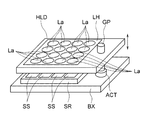
- FIG. 2 is a perspective view schematically showing the relationship between the compound-eye optical system LH and the image sensor SR.
- the compound-eye optical system LH is held by a holder HLD, and the holder HLD has a through-hole that engages with a guide pin GP implanted through a piezo-type actuator ACT in a lens frame BX holding an imaging element SR. is doing.
- a minute clearance is provided between the through hole of the holder HLD and the guide pin GP.
- the actuator ACT is not driven, the holder HLD is stationary with respect to the guide pin GP due to frictional force.
- the guide pin GP is vibrated by a piezo-type actuator ACT provided at the base of the guide pin GP, so that the holder HLD and the compound-eye optical system LH can be moved relative to the image sensor SR in the optical axis direction. That is, the holder HLD, the guide pin GP, and the lens frame BX constitute a support member that supports the compound eye optical system LH so as to be relatively movable in the optical axis direction with respect to the imaging element SR.
- the details of the piezo actuator ACT are described in, for example, Japanese Patent Application Laid-Open No. 2013-062997. Therefore, detailed description of the configuration and operation is omitted in this specification.
- a voice coil motor, an actuator using a shape memory alloy, or the like can be used.
- the compound eye optical system LH includes at least one lens array in which a plurality of lenses are integrally formed in a matrix.
- the lens array can be formed as a single piece of a plurality of lenses arranged in a plane by molding resin, glass, or the like with a mold.
- the integrally molded product is preferable because it is easy to obtain an inexpensive and highly accurate array lens.
- a lens array in which a plurality of lens portions such as a resin are formed on a transparent substrate such as glass may be used.
- a plurality of lens arrays LA1 and LA2 may be arranged so as to overlap in the optical axis direction, or only one lens array may be included.
- the single-eye optical system La is composed of a plurality of lenses
- the single-eye optical system La is composed of one lens.
- the entire compound-eye optical system is integrated and driven integrally by the actuator ACT.
- a plurality of imaging regions SS are formed on the imaging element SR corresponding to the single-eye optical system La.
- An optical image formed by each single-eye optical system La is formed in each imaging region SS and outputs an image signal.
- the image processing unit 1 includes an image composition unit 1a and an image correction unit 1b.
- the image synthesizing unit 1a performs necessary image processing such as inversion processing, distortion processing, shading processing, and the like on the image signals from the plurality of imaging regions SS formed by the compound eye optical system LH, and synthesizes them to synthesize one image. Generate image data.
- the image correction unit 1b performs image correction such as ghost correction, shading correction, and distortion correction, and outputs the result as a composite image ML.
- the output composite image ML is stored in the memory 3.
- the arrangement direction of the single-eye optical system of the compound-eye optical system LH and the image pickup element SR should be parallel to each other.
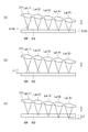
- the holder HLD is guided by one guide pin GP. If so, the holder HLD tends to be inclined with respect to the guide pin GP. A similar phenomenon may occur even if two guide pins are provided or a fixed guide that does not contribute to driving is provided separately. Then, as shown in FIG. 3, the distance between the single-eye optical system La and the imaging region SS is individually different.
- the compound-eye optical system LH when the compound-eye optical system LH is tilted, the focus position of each single-eye optical system La is shifted, and the degree of blur differs for each single-eye image, but it is desirable to minimize the width of this variation.
- the blur amount is detected for each image signal in the imaging region corresponding to each single-eye optical system, and the compound eye optical system is positioned at the position where the average value of the blur amount is minimized.
- the focus may be adjusted by moving the system LH.
- the amount of blur has a correlation with the focus position of the single-eye optical system La, the corresponding imaging region SS, and the amount of deviation in the optical axis direction.
- the compound-eye optical system LH is illustrated as including one lens array in which five single-eye optical systems La (1) to La (5) are arranged in the tilt direction. It is assumed that the angle with respect to the image sensor SR does not change even when the compound eye optical system LH is moved up and down.
- the compound eye optical system LH is moved up and down to change the distance from the image sensor SR, and the image from the imaging region SS on which the optical images are formed by the individual eye optical systems La (1) to La (5).
- High frequency components are extracted from the signal. The amount of the high frequency component is used as an evaluation value for focus adjustment.
- the graph of FIG. 5 is obtained for each individual eye optical system.
- the amount of the high-frequency component reflects the focus state of the single-eye optical system, and the peak position where the high-frequency component is the largest is the position focused on the region SS corresponding to the single-eye optical system. That is, the evaluation value represents the focus position of the single-eye optical system.
- the compound eye optical system LH is inclined, as shown in FIG. 5, in each of the five single-eye optical systems La (1) to La (5), the compound eye optical system LH is located with respect to the image sensor SR. The optimum focus position is obtained at different positions, that is, the focus is achieved.
- the imaging region SS when the single-eye optical system La (5) closest to the imaging region SS is set to a focused position (corresponding to c in FIG. 5), the imaging region SS
- the amount of deviation ⁇ 1 (the maximum amount of deviation at the position shown in FIG. 4B) between the focusing position of the single-eye optical system La (1) farthest from the imaging region SS and the imaging region SS increases.
- the high-frequency component of the image formed in the imaging region SS by the eye optical system La (1) decreases, and the amount of blur increases ( ⁇ c in FIG. 5).
- FIG. 4C when the single-eye optical system La (1) that is farthest from the imaging region SS is set to a focused position (corresponding to a in FIG.
- the imaging region SS The distance ⁇ 2 (maximum deviation at the position shown in FIG. 4C) between the focus position of the single-eye optical system La (5) and the imaging region SS that is closest to the image pickup area SS increases, and the individual The high-frequency component of the image formed in the imaging region SS by the eye optical system La (5) decreases, and the amount of blur increases ( ⁇ a in FIG. 5).
- the deviation amount ⁇ 2a between the focus position of the single-eye optical system La (5) and the imaging region SS that is closest to the SS is suppressed to an absolute value ( ⁇ 1, ⁇ 2).
- the difference between the blur amounts of the individual optical systems at the position b is minimum ( ⁇ b in FIG.
- the maximum deviation amount at the position b in FIG. 5 is minimum
- the high-frequency component is maximum.
- An image formed on the imaging region SS by each individual optical system La (1) to La (5) Therefore, the image synthesized by the super-resolution processing also has high image quality.
- the focus state of the compound eye optical system can be determined. 3 and 4, for easy understanding, the inclination of the compound-eye optical system LH is exaggerated, but in reality, this inclination is small and is shifted as shown in FIG. By minimizing the amount, it can be set so that all the single-eye optical systems are in focus.
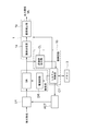
- FIG. 6 is a part of the image pickup apparatus shown in FIG. 1, and executes the specification of the optimum imaging region, the search for the optimum focus position, and the autofocus configuration for grasping the focus state of the compound eye optical system.
- FIG. 2 is a more detailed diagram of a circuit block diagram. Components common to those in FIG. 1 are denoted by the same reference numerals.
- the control circuit 10 includes a central processing circuit and the like, exchanges image information with the image processing unit 1 and the memory 3, and controls the actuator ACT and the drive circuit DR of the image sensor SR.
- a system control unit CT that controls and an evaluation value calculation unit CL that calculates an evaluation value based on a plurality of image signals obtained from each imaging region of the imaging element SR corresponding to each single-eye optical system.
- the system control unit CT drives the actuator ACT based on the data sent from the evaluation value calculation unit CL.
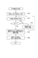
- the control circuit 10 executes the process for determining the imaging area for grasping the focus state shown in the flowchart of FIG. For example, at the time of inspection after assembly, first, the actuator ACT is driven to move the compound eye optical system LH to an initial position (step S10), and subject light from a chart or the like is transmitted through each individual optical system in the compound eye optical system LH. An optical image is formed in all the imaging regions of the imaging element SR, photoelectrically converted, and then an image signal is output in accordance with a control signal from the drive circuit DR that receives an instruction from the system control unit CT. A high-frequency component is extracted from the image signal by filtering in the evaluation value calculation unit CL (step S12).
- the system control unit CT drives the actuator ACT to move the compound eye optical system LH in the optical axis direction, captures the chart again, and extracts a high frequency component from the image signal.
- the graph shown in FIG. 5 is obtained for all the imaging regions. Therefore, at the position where the maximum shift amount of the focus position is the minimum, An imaging region corresponding to the single-eye optical system that minimizes the amount of positional deviation is selected (step S18), and information (region number or the like) representing this imaging region is stored in the memory 3 (step S20).
- the control circuit 10 executes the focus control processing shown in the flowchart of FIG. Specifically, the system control unit CT in the control circuit 10 reads information such as an area number from the memory 3, and selects an imaging area corresponding to the information such as the area number (step S100). Then, a high frequency component is detected from the image signal from the selected imaging region while changing the position of the compound eye optical system LH (step S102), and a graph as shown in FIG. 9 is acquired based on the detected value. Then, the focus position d as the peak position is obtained (step S104), and the system control unit CT further drives the actuator ACT to move the compound eye optical system LH to the focus position d, thereby performing an autofocus operation ( Step S106).
- the system control unit CT in the control circuit 10 reads information such as an area number from the memory 3, and selects an imaging area corresponding to the information such as the area number (step S100). Then, a high frequency component is detected from the image signal from the selected imaging region while changing the position of the compound eye optical system L
- an image with minimum focus shift can be obtained in all the imaging regions, so that the super-resolution processing can be performed as described above to output the composite image ML.
- finding the optimal focus position for each eye optical system and performing a focusing operation results in an enormous amount of image signals, which takes time for image processing and moves with autofocus.
- the subject may not be followed.
- the compound-eye optical system LH including a plurality of single-eye optical systems is integrally configured, all the single-eye optical systems move integrally, so that image processing is performed on image signals in all regions.
- the focus state can be grasped by obtaining the area to be selected in advance and storing the information, selecting the area specified by the information and calculating the evaluation value. Then, focusing can be performed appropriately and quickly by performing focusing based on the evaluation value.
- each individual optical system and the imaging region are at the optimum focus position.
- Information corresponding to the optimum distance in the optical axis direction which is the distance between the reference portion of the compound-eye optical system LH (for example, a mark provided between a specific pair of adjacent lenses) and the image sensor SR, can also be obtained. .
- the optimal focus position between the single-eye optical system and the imaging region differs between the single-eye optical systems due to the tilting of the compound-eye optical system, and the obtained optimal optical axis distances vary, so the median of the variation
- the imaging area corresponding to the single-eye optical system that indicates the optimum optical axis direction distance closest to is selected, and this imaging area is stored in the memory 3.
- the focus position is already shifted when the compound-eye optical system LH is parallel to the imaging region due to warpage of the compound-eye optical system or manufacturing errors of the individual-eye imaging systems.
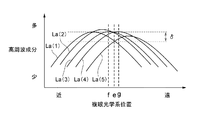
- the graph relating to the high frequency component based on the image signal output from each imaging region has various shapes as shown in FIG.
- the variation in the amount of shift in the focus position between the single-eye optical systems is the position of e, but there is no imaging region where the peak is at this position.
- imaging area (focus position f) corresponding to the single-eye optical system La (3) and an imaging area (focus position g) corresponding to the single-eye optical system La (4) as imaging areas close to this.
- a plurality of imaging areas close to the center value of the variation may be selected, and these imaging areas may be stored in the memory 3.
- it is possible to grasp the focus state and perform the focus adjustment in a short time by selecting a number of imaging regions smaller than the total number of the single-eye optical systems.
- weighted averages of evaluation values related to focus positions based on high-frequency components obtained from image signals from a plurality of selected imaging areas (La (3), La (4)) are virtually focused.
- the position is obtained, and the actuator ACT drives the compound eye optical system LH.
- the weighted average means that, for example, an imaging region (La (4)) close to the center value of variation is weighted (for example, 0.7 times), and an imaging region (La (3)) far from the center value of variation is used. It is conceivable to reduce the weight (for example, 0.3 times) and add both.
- an imaging area close to the center position of the compound eye optical system LH can be selected and stored in the memory 3.
- the focus operation can be performed accurately in a short time by selecting at least one region smaller than that from the plurality of regions and performing the focus operation.
- FIG. 11 is a block diagram according to another embodiment, and the circuit block shown in FIG. 6 has a configuration in which a tilt axis detection unit TD is provided.
- the compound eye optical system LH when the compound eye optical system LH is moved, the image signal from all the imaging regions is filtered by the evaluation value calculation unit CL, and the high-frequency component is extracted.
- the TD estimates a plurality of imaging regions that output image signals having peaks at the same position, and notifies the system control unit 2 that the corresponding single-eye imaging system is on the tilt axis TX.
- These imaging areas can be stored in the memory 3.
- the single-eye imaging system is not always on the tilt axis TX. Therefore, when high-frequency components are extracted from image signals from all imaging regions, the tilt axis detection unit TD selects an imaging region in which the corresponding single-eye imaging system is estimated to be close to the tilt axis TX, and these The imaging area can be stored in the memory 3.
- the focus value is virtually obtained by weighted average of the evaluation values related to the focus position based on the high frequency components obtained from the image signals from the plurality of selected imaging areas, and the actuator ACT performs the compound eye optical system LH. Is preferably driven.
- FIG. 12 is a perspective view schematically showing a compound eye optical system LH and an image sensor SR according to a modification.
- the single-eye optical system La and the imaging region SS of the compound-eye optical system LH are not limited to 4 rows and 4 columns, and may be, for example, 3 rows and 3 columns as shown in FIG. 12, or 5 as shown in FIG. It may be a column (for example, 5 rows and 5 columns).
- the imaging region is not limited to being selected at the time of inspection after the imaging device is assembled, but may be selected periodically, for example, every time the imaging device is powered on.
- the information stored in the memory 3 may be information indicating the area corresponding to a specific eye-specific optical system designated in advance. Also in this case, the memory 3 may store information indicating a plurality of the areas.
- the compound eye optical system is selected from the plurality of areas based on the information stored in the memory 3. At least one area close to the center of the system LH is selected, and when there is one selected area, the driving element is driven based on the evaluation value related to the focus position extracted from the image signal from the area, and the selected area is selected. When there are a plurality of the regions, the drive element may be driven based on the weighted average value.
- a display unit may be provided in the imaging apparatus to notify the user of the focus state of the compound eye optical system. Then, the user may manually change the position of the compound eye optical system with respect to the image sensor based on the display content.
Landscapes
- Physics & Mathematics (AREA)
- General Physics & Mathematics (AREA)
- Optics & Photonics (AREA)
- Engineering & Computer Science (AREA)
- Computer Vision & Pattern Recognition (AREA)
- Studio Devices (AREA)
- Automatic Focus Adjustment (AREA)
- Focusing (AREA)
Abstract
複眼光学系を用いながらも適切なフォーカシング動作を迅速に行うことが出来る画像入力装置及び画像入力装置のフォーカス判別方法を提供する。この画像入力装置は、並列的に配置された複数の個眼光学系を備え一体的に構成された複眼光学系と、各個眼光学系により光学像がそれぞれ結像される複数の領域を備え、前記領域に結像される光学像を画像信号に変換する撮像素子と、前記撮像素子に対して、前記複眼光学系を光軸方向に相対的に移動可能に支持する支持部材と、前記画像信号に基づいて、前記個眼光学系のフォーカス状態を表す評価値を算出する評価値算出部を含む制御回路と、を有し、前記制御回路は、前記複数の領域からそれらよりも少ない数の少なくとも一つの前記領域を選択し、選択された少なくとも一つの前記領域からの画像信号の評価値に基づいて、前記複眼光学系のフォーカス状態を判別する。
Description
本発明は、1つの固体撮像素子上に複眼光学系によって形成された複数の像に基づいて1枚の画像を得ることができる画像入力装置及びそのフォーカス判別方法に関する。
近年、スマートフォンやタブレット型パーソナルコンピュータなどに代表される薄型の撮像装置付き携帯端末が急速に普及している。しかるに、このような薄型の携帯端末に搭載される撮像装置には、高解像度を有しながらも薄形でコンパクトであることが要求されている。このような要求に対応するために、撮像レンズの光学設計による全長短縮やそれに伴う誤差感度増大に対応した製造精度向上を行ってきたが、さらなる要求に対応するためには、従来の単一の撮像レンズと撮像素子の組み合わせで像を得るという構成では限界があり、従来とは発想を変えた光学系の開発が期待されている。
これに対し、撮像素子の撮像領域を分割して、それぞれに対応するレンズを含む光学系(以下、個眼光学系という)を配置し、得られた画像を処理することで、最終的な画像出力を行う複眼撮像装置に用いられる、複眼光学系と呼ばれる光学系が、薄形化への要求に対応するために注目されている。特許文献1には、複眼光学系を用いて画像を形成する撮像装置が開示されている。
ところで、より高品質な画像を形成するためには、複眼光学系を用いた撮像装置においても、撮像素子に対して複眼光学系を光軸方向に移動するフォーカシング機構が必要になる。しかるに、複数の個眼光学系を個々に独立して移動させることは、複雑な機構が必要になるから困難である。そこで、フォーカシングのため、複眼光学系全体を一体的に移動することが考えられる。しかるに、フォーカシングのために光軸方向に動かすための駆動機構やガイド機構はできるだけ簡素であることが好ましく、これらを簡略化するには、複眼光学系をガイドピンなど1か所のみで支持することが望ましい。しかし、簡略化の結果、ガイドピンなどの支持部材に対して複眼光学系が傾きやすくなる。複眼光学系が傾くと、並列に配置された複数の個眼光学系と撮像面との距離が一定ではなくなってしまい、このため個眼光学系における最適なピント位置と撮像面とがずれる恐れがある。このずれが大きくなると光学像がぼけてしまい、高品質な画像を得られない。しかしながら、特許文献1では、このような複眼光学系の傾き等に起因するフォーカスの問題について何ら言及されていない。
本発明は、かかる従来技術の問題点に鑑みてなされたものであり、複眼光学系を用いながらも適切なフォーカシング動作を迅速に行うことが出来る画像入力装置及び画像入力装置のフォーカス判別方法を提供することを目的とする。
本発明に係る画像入力装置は、
並列的に配置された複数の個眼光学系を備え一体的に構成された複眼光学系と、
各個眼光学系により光学像がそれぞれ結像される複数の領域を備え、前記領域に結像される光学像を画像信号に変換する撮像素子と、
前記撮像素子に対して、前記複眼光学系を光軸方向に相対的に移動可能に支持する支持部材と、
前記画像信号に基づいて、前記個眼光学系のフォーカス状態を表す評価値を算出する評価値算出部を含む制御回路と、を有し、
前記制御回路は、前記複数の領域からそれらよりも少ない数の少なくとも一つの前記領域を選択し、選択された少なくとも一つの前記領域からの画像信号の評価値に基づいて、前記複眼光学系のフォーカス状態を判別することを特徴とする。
並列的に配置された複数の個眼光学系を備え一体的に構成された複眼光学系と、
各個眼光学系により光学像がそれぞれ結像される複数の領域を備え、前記領域に結像される光学像を画像信号に変換する撮像素子と、
前記撮像素子に対して、前記複眼光学系を光軸方向に相対的に移動可能に支持する支持部材と、
前記画像信号に基づいて、前記個眼光学系のフォーカス状態を表す評価値を算出する評価値算出部を含む制御回路と、を有し、
前記制御回路は、前記複数の領域からそれらよりも少ない数の少なくとも一つの前記領域を選択し、選択された少なくとも一つの前記領域からの画像信号の評価値に基づいて、前記複眼光学系のフォーカス状態を判別することを特徴とする。
本発明においては、複数の領域からそれよりも少ない数の少なくとも1つの領域を選択し、選択された少なくとも一つの領域からの画像信号の評価値に基づいて、フォーカス調整を行うので、画像処理に必要な時間が短縮され、短時間で高品質な画像を得ることができる。
本発明の具体的な態様又は観点では、生成する画像信号から前記評価値が算出されるべき少なくとも一つの前記領域を示す情報を記憶するメモリをさらに備え、前記制御回路は、前記メモリに記憶された前記情報に基づいて、少なくとも一つの前記領域を選択する。
また、本発明の具体的な態様又は観点では、前記支持部材は、駆動素子を有し、該駆動素子の駆動によって前記複眼光学系を光軸方向に移動させるものであり、前記制御回路は、選択された少なくとも一つの前記領域からの画像信号に基づいて算出された前記評価値に基づいて前記駆動素子を駆動して前記複眼光学系のフォーカス調整を行う。
また、本発明の具体的な態様又は観点では、前記制御回路は、予め、前記駆動素子を駆動して前記複眼光学系と前記撮像素子との間の距離を変更しつつ、前記評価値算出部により、前記複数の領域からの画像信号から抽出した高周波成分に基づいて、各個眼光学系と、それに対応する前記領域とが最適なフォーカス位置となるときの、前記複眼光学系の基準部位と前記撮像素子との間の距離である最適光軸方向距離に対応する情報をそれぞれ求め、複数の前記最適光軸方向距離の中央値に最も近い前記情報を示す前記個眼光学系に対応する前記領域を選択し、その領域を示す情報を前記メモリに記憶する。
また、本発明の具体的な態様又は観点では、前記制御回路は、予め、前記駆動素子を駆動して前記複眼光学系と前記撮像素子との間の距離を変更しつつ、前記評価値算出部により、前記複数の領域からの画像信号から抽出した高周波成分に基づいて、各個眼光学系と、それに対応する前記領域とが最適なフォーカス位置となるときの、前記複眼光学系の基準部位と前記撮像素子との間の距離である最適光軸方向距離に対応する情報をそれぞれ求め、複数の前記最適光軸方向距離の中央値に近い情報を示す前記個眼光学系に対応する前記領域を複数個選択し、それらの領域を示す情報を前記メモリに記憶し、フォーカス調整を行う際には、前記メモリに記憶された複数の前記領域からの画像信号に基づいて算出された複数の前記評価値の加重平均値に基づいて、前記駆動素子を駆動する。
また、本発明の具体的な態様又は観点では、前記制御回路は、予め、前記駆動素子を駆動して前記複眼光学系と前記撮像素子との間の距離を変更しつつ、前記評価値算出部により、前記複数の領域からの画像信号から抽出した高周波成分に基づいて、前記撮像素子に対する前記複眼光学系の距離が異なる複数の位置において各領域に対応する前記個眼光学系のピント位置のずれ量に対応する情報を求め、求めた該情報に基づいて前記ピント位置の最大ずれ量が最小となる位置を特定し、該位置において、前記ピント位置のずれ量が最小となる前記個眼光学系に対応する前記領域を選択し、その領域を示す情報を前記メモリに記憶する。
また、本発明の具体的な態様又は観点では、前記制御回路は、予め、前記駆動素子を駆動して前記複眼光学系と前記撮像素子との間の距離を変更しつつ、前記評価値算出部により、前記複数の領域からの画像信号から抽出した高周波成分に基づいて、前記撮像素子に対する前記複眼光学系の距離が異なる複数の位置において各領域に対応する前記個眼光学系のピント位置のずれ量に対応する情報を求め、求めた該情報に基づいて前記ピント位置の最大ずれ量が最小となる位置を特定し、該位置において、前記ピント位置のずれ量が最小となる前記個眼光学系に対応する前記領域を複数個選択し、それらの領域を示す情報を前記メモリに記憶し、フォーカス調整を行う際には、前記メモリに記憶された複数の前記領域からの画像信号に基づいて算出された複数の前記評価値の加重平均値に基づいて、前記駆動素子を駆動する。
また、本発明の具体的な態様又は観点では、前記制御回路は、前記複数の領域からの画像信号から抽出した高周波成分に基づいて、前記複眼光学系のチルト軸を求めるチルト軸検出部をさらに有し、予め、前記チルト軸検出部により求めた前記チルト軸上に位置する前記個眼光学系に対応する前記領域を選択し、その領域を示す情報を前記メモリに記憶する。
また、本発明の具体的な態様又は観点では、前記制御回路は、前記複数の領域からの画像信号から抽出した高周波成分に基づいて、前記複眼光学系のチルト軸を求めるチルト軸検出部をさらに有し、予め、前記チルト軸検出部により求めた前記チルト軸に最も近い前記個眼光学系に対応する前記領域を選択し、その領域を示す情報を前記メモリに記憶する。
また、本発明の具体的な態様又は観点では、前記メモリに記憶される情報は、予め、指定された特定の個眼光学系に対応する前記領域を示す情報である。
また、本発明の具体的な態様又は観点では、前記メモリは、複数の前記領域を示す情報を記憶しており、前記制御回路は、前記複眼光学系のフォーカス調整を行う際には、前記メモリに記憶された情報に基づいて、複数の前記領域の中から前記複眼光学系の中心に近い少なくともの一つの前記領域を選択し、選択された前記領域が一つの場合はその領域からの画像信号に基づいて算出された前記評価値に基づいて、前記駆動素子を駆動し、選択された前記領域が複数の場合はそれらの領域からの画像信号に基づいて算出された複数の前記評価値の加重平均値に基づいて、前記駆動素子を駆動する。
また、本発明の具体的な態様又は観点では、前記複眼光学系は、平面状に並ぶ複数のレンズを一体成形したレンズアレイを有する。
本発明に係る画像入力装置のフォーカス判別方法は、
並列的に配置された複数の個眼光学系を備え一体的に構成された複眼光学系と、各個眼光学系により光学像がそれぞれ結像される複数の領域を備え、前記領域に結像された光学像を画像信号に変換する撮像素子と、前記複眼光学系を前記撮像素子に対して光軸方向に相対的に移動可能に支持する支持部材と、を備える画像入力装置のフォーカス判別方法において、
前記複数の領域からそれよりも少ない数の少なくとも一つの前記領域を選択し、
選択された少なくとも一つの前記領域からの画像信号に基づいて、フォーカス状態を表す評価値を算出し、算出された評価値に基づいて、前記複眼光学系のフォーカス状態を判別することを特徴とする。
並列的に配置された複数の個眼光学系を備え一体的に構成された複眼光学系と、各個眼光学系により光学像がそれぞれ結像される複数の領域を備え、前記領域に結像された光学像を画像信号に変換する撮像素子と、前記複眼光学系を前記撮像素子に対して光軸方向に相対的に移動可能に支持する支持部材と、を備える画像入力装置のフォーカス判別方法において、
前記複数の領域からそれよりも少ない数の少なくとも一つの前記領域を選択し、
選択された少なくとも一つの前記領域からの画像信号に基づいて、フォーカス状態を表す評価値を算出し、算出された評価値に基づいて、前記複眼光学系のフォーカス状態を判別することを特徴とする。
本発明によれば、複眼光学系を用いながらも適切なフォーカシング動作を迅速に行うことが出来る画像入力装置を提供することができる。
以下、本発明に係る複眼光学系を用いた撮像装置(画像入力装置)の一実施形態を説明する。複眼光学系は、1つの撮像素子に対して複数のレンズがアレイ状に(並列に)配置された光学系であり、超解像タイプと視野分割タイプとに通常分けられる。ここで、超解像タイプとは、個々のレンズによって結像された同方向の僅かに視野のずれた画像から画像処理によって1つの高解像度の画像を得る方式に用いられる複眼光学系を指す。また、視野分割タイプとは、個々のレンズによって結像された異なる視野の画像を、画像処理よって各視野の画像をつなぎ合わせることで1つの画像を得る方式に用いられる複眼光学系を指す。
図1に本実施の形態にかかる撮像装置を模式的に示す。図1に示すように、撮像装置DUは、撮像ユニットLU,画像処理部1,全体の制御を司る制御回路10,メモリ3等を有している。そして、撮像ユニットLUは、1つの撮像素子SRと、その撮像素子SRに対して、光軸を平行にして並列的に配置された複数の個眼光学系によって複数の結像を行う複眼光学系LHを有している。撮像素子SRとしては、例えば複数の画素を有するCCD型イメージセンサー,CMOS型イメージセンサー等の固体撮像素子が用いられる。撮像素子SRの光電変換部である受光面に複数の撮像領域SSが形成され、この撮像領域に被写体の光学像がそれぞれ形成されるように複眼光学系LHが設けられているので、複眼光学系LHによって形成された光学像は、撮像素子SRによって電気的な信号に変換される。図1では、複眼光学系が超解像タイプのものとして示されているが、視野分割タイプのものにも適用可能である。
図1において、複眼光学系LHは、駆動素子であるアクチュエータACTにより光軸方向に移動可能となっている。アクチュエータACTは、制御回路10からの信号により駆動されるようになっている。
図2は、複眼光学系LHと、撮像素子SRとの関係を模式的に示す斜視図である。複眼光学系LHは、ホルダHLDにより保持されており、ホルダHLDは、撮像素子SRを保持した鏡枠BXにピエゾ型アクチュエータACTを介して植設されたガイドピンGPに係合する貫通孔を有している。ホルダHLDの貫通孔とガイドピンGPとの間には微小なクリアランスが設けられており、アクチュエータACTを駆動していないときは、ホルダHLDは摩擦力によりガイドピンGPに対して静止している。ガイドピンGPの根元に設けられたピエゾ型アクチュエータACTによって、ガイドピンGPを振動させることで、ホルダHLDと複眼光学系LHとを撮像素子SRに対して光軸方向に相対移動可能としている。つまり、ホルダHLDとガイドピンGPと鏡枠BXとで、複眼光学系LHを撮像素子SRに対して光軸方向に相対的に移動可能に支持する支持部材を構成する。ピエゾ型アクチュエータACTについては、例えば特開2013-062997号公報に詳細が記載されているため、本明細書では構成及び動作について詳しい説明を省略する。これ以外に、ボイスコイルモータや、形状記憶合金を用いたアクチュエータなどを用いることもできる。
複眼光学系LHには、マトリクス状に複数のレンズが一体的に形成されているレンズアレイが少なくとも一つ含まれる。レンズアレイは、樹脂やガラスなどを金型で成形することにより、平面状に並ぶ複数のレンズが一体成形されたものとして形成することができる。一体成型品は、安価で高精度なアレイレンズを得やすく好ましいものである。一体成型品外にも、ガラスなどの透明基板に樹脂などの複数のレンズ部を形成してなるレンズアレイを用いてもよい。図1に示すように、複数のレンズアレイLA1、LA2を光軸方向に重ねて配置してもよいし、レンズアレイを一つだけ含むものであってもよい。前者の場合、個眼光学系Laは複数のレンズから構成され、後者の場合、個眼光学系Laは1つのレンズから構成されることになる。いずれにしても、複眼光学系全体が一体化された構成となり、アクチュエータACTによって一体的に駆動される。一方、撮像素子SR上には、個眼光学系Laに対応して、複数の撮像領域SSが形成されている。各個眼光学系Laにより結像された光学像は、各撮像領域SSに結像され、それぞれ画像信号を出力するようになっている。
図1に示すように、画像処理部1は、画像合成部1aと、画像補正部1bと、を有している。画像合成部1aは、複眼光学系LHにより形成された複数の撮像領域SSからの画像信号に反転処理、歪曲処理、シェーディング処理等の必要な画像処理を施し、これらを合成して1枚の合成画像データを生成する。さらに、画像補正部1bにおいて、ゴースト補正、シェーディング補正、歪曲補正等の画像補正を行って、合成画像MLとして出力する。出力された合成画像MLは、メモリ3に記憶される。
ところで、本来的には複眼光学系LHの個眼光学系の並び方向と撮像素子SRとは平行であるべきだが、図2に示すように、ホルダHLDを1本のガイドピンGPでガイドしていると、ガイドピンGPに対してホルダHLDが傾きがちになる。同様な事象はガイドピンを2本にしても、駆動には寄与しない固定ガイドを別に設けても生じる可能性がある。すると、図3に示すように、個眼光学系Laと撮像領域SSとの距離が、個々に異なるようになる。各個眼画像から超解像処理により一つの高解像度画像を得る場合、各個眼光学系La全てが合焦している場合に最大の解像度復元効果があるが、ボケ量が多い個眼画像が増えるほど解像度復元効果が少なくなり、高解像度の画像が得にくくなる。
よって、複眼光学系LHが傾いた場合、各個眼光学系Laの合焦位置がずれることになり、個眼画像毎にボケ具合が異なるが、このバラツキの幅を最小にすることが望ましい。ボケ量のバラツキの幅を最小限にするためには、例えば、各個眼光学系に対応する撮像領域の画像信号毎にボケ量を検出し、ボケ量の平均値が最小になる位置に複眼光学系LHを移動することにより、フォーカスを調整すればよい。この場合、ボケ量は、個眼光学系Laのピント位置と、それに対応する撮像領域SSと光軸方向のずれ量と相関がある。
図4(a)~(c)は、複眼光学系LHと撮像素子SRとが傾いた状態における、各個眼光学系のピント位置を示している。ここでは、理解を容易にするため、複眼光学系LHは、傾き方向に5つの個眼光学系La(1)~La(5)が並んだレンズアレイを一つ含むものとして図示し、また、複眼光学系LHを上下させても撮像素子SRに対する角度は変化しないものとする。まず、複眼光学系LHを上下に移動させて、撮像素子SRからの距離を変えつつ、各個眼光学系La(1)~La(5)により光学像が結像された撮像領域SSからの画像信号から、高周波成分を抽出する。この高周波成分の量をフォーカス調整のための評価値とする。
この高周波成分を縦軸に、複眼光学系LHの位置を横軸にとると、各個眼光学系に関して図5のグラフが得られる。高周波成分の量は個眼光学系のフォーカス状態を反映しており、高周波成分が最も多くなるピーク位置が、個眼光学系が対応する領域SSにピントの合った位置になる。つまり、評価値は個眼光学系のフォーカス位置を表している。ここで、複眼光学系LHが傾いていると、図5に示すように、5つの個眼光学系La(1)~La(5)それぞれにおいて、撮像素子SRに対して、複眼光学系LHが異なる位置で最適なフォーカス位置をとる、つまり、ピントが合うことになる。
例えば、図4(b)に示すように、撮像領域SSとの距離が最も近い個眼光学系La(5)を、ピントの合った位置(図5のcに相当)とすると、撮像領域SSとの距離が最も遠い個眼光学系La(1)のピント位置と、撮像領域SSとのずれ量Δ1(図4(b)に示される位置での最大ずれ量)が大きくなり、これにより個眼光学系La(1)により撮像領域SSに結像された画像の高周波成分が少なくなり、ボケ量が大きくなる(図5のδc)。一方、図4(c)に示すように、撮像領域SSとの距離が最も遠い個眼光学系La(1)を、ピントの合った位置(図5のaに相当)とすると、撮像領域SSとの距離が最も近い個眼光学系La(5)のピント位置と、撮像領域SSとのずれ量Δ2(図4(c)に示される位置での最大ずれ量)が大きくなり、これにより個眼光学系La(5)により撮像領域SSに結像された画像の高周波成分が少なくなり、ボケ量が大きくなる(図5のδa)。
これに対し、図4(a)に示すように、撮像領域SSとの距離が個眼光学系La(1)よりも小さく個眼光学系La(5)よりも大きい個眼光学系La(3)を、ピントの合った位置(図5のb)とすると、撮像領域SSとの距離が最も遠い個眼光学系La(1)のピント位置と撮像領域SSとのずれ量Δ1a、及び撮像領域SSとの距離が最も近い個眼光学系La(5)のピント位置と撮像領域SSとのずれ量Δ2aが、いずれも絶対値で小さく(<Δ1,Δ2)抑えられ、これにより、図5のbの位置での各個眼光学系のボケ量の差が最小(図5のδb)となり(換言すれば、図5のbの位置での最大ずれ量が最小となり)、すなわち高周波成分が最大となり、各個眼光学系La(1)~La(5)により撮像領域SSに結像された画像から超解像処理により合成される画像も高画質なものとなる。このように、評価値を算出することによって、複眼光学系のフォーカス状態を判別することができる。なお、図3、図4においては、理解を容易にするため、複眼光学系LHの傾きは誇張して図示してあるが、実際にはこの傾きは小さく、図4(a)のようにずれ量を最小化することで、全個眼光学系のピントが合うように設定できる程度のものである。
図6は、図1に示す撮像装置の一部であって、複眼光学系のフォーカス状態を把握するのに最適な撮像領域の特定と、最適なピント位置の探索と、オートフォーカス構成とを実行する回路ブロック図のより詳細な図である。図1と共通する構成には同じ符号を付している。図6に示すように、制御回路10には、中央演算回路等を含み、画像処理部1やメモリ3との間で画像情報をやり取りし、アクチュエータACTや撮像素子SRの駆動回路DRの制御を司るシステム制御部CTと、各個眼光学系に対応する撮像素子SRの各撮像領域から得られる複数の画像信号に基づいて評価値を算出する評価値算出部CLとが設けられている。システム制御部CTは、評価値算出部CLから送られるデータに基づいて、アクチュエータACTを駆動する。
制御回路10は、図7のフローチャートに示した、フォーカス状態を把握するための撮像領域を決定するための処理を実行する。例えば、組み立て後の検査時に、まず、アクチュエータACTを駆動して複眼光学系LHを初期位置に移動させ(ステップS10)、チャートなどからの被写体光を、複眼光学系LHにおける各個眼光学系を介して撮像素子SRの全ての撮像領域に光学像を結像させ、光電変換した後、システム制御部CTから指示を受けた駆動回路DRからの制御信号に従い画像信号を出力させる。その画像信号を、評価値算出部CLにてフィルタ処理により高周波成分を抽出する(ステップS12)。次いで、システム制御部CTが、アクチュエータACTを駆動して複眼光学系LHを光軸方向に移動させ、再びチャートの撮像を行って、画像信号から高周波成分を抽出する。これを移動範囲内の全ての位置について繰り返すことで(ステップS14、S16)、全ての撮像領域に関して、図5に示すグラフが得られるので、ピント位置の最大ズレ量が最小となる位置において、ピント位置のずれ量が最小となる個眼光学系に対応する撮像領域を選択し(ステップS18)、この撮像領域を表す情報(領域番号等)をメモリ3に記憶する(ステップS20)。
その後、実際の撮像時には、制御回路10が図8のフローチャートに示したフォーカス制御処理を実行する。具体的には、制御回路10内のシステム制御部CTが、メモリ3から領域番号等の情報を読み出し、その領域番号等の情報に相当する撮像領域を選択する(ステップS100)。そして、複眼光学系LHの位置を変化させつつ、選択された撮像領域からの画像信号から高周波成分を検出し(ステップS102)、検出した値に基づいて、図9に示すようなグラフを取得して,そのピーク位置としてのピント位置dを求め(ステップS104)、更にシステム制御部CTが、アクチュエータACTを駆動してピント位置dに複眼光学系LHを移動させることにより、オートフォーカス動作を行う(ステップS106)。これにより、全ての撮像領域においてピントのズレが最小限の画像が得られるので、上述したように超解像処理を行って合成画像MLを出力することができる。全ての領域からの画像信号に基づいて、個眼光学系毎に最適なピント位置を求めて、フォーカシング動作を行うと、画像信号が膨大となり、その画像処理に時間がかかり、オートフォーカスで移動する被写体を追うような場合、被写体に追従できない恐れがある。これに対して、複数の個眼光学系を備える複眼光学系LHが一体的に構成されていれば、全ての個眼光学系が一体的に移動するので、全ての領域の画像信号について画像処理をする必要はなく、予め、選択されるべき領域を求めてその情報を記憶しておき、その情報で特定される領域を選択して評価値を算出すれば、フォーカス状態を把握できる。そして、この評価値に基づきフォーカシングを行うことで、適切かつ迅速にフォーカス動作を行うことができる。
変形例として、撮像領域からの画像信号を、評価値算出部CLにて画像処理を行って、高周波成分を抽出することにより、各個眼光学系と撮像領域とが最適フォーカス位置となるときの、複眼光学系LHの基準部位(例えば、特定の隣り合う一対のレンズの間に設けたマーク)と撮像素子SRとの間の距離である最適光軸方向距離に相当する情報をそれぞれ求めることもできる。かかる場合、複眼光学系が傾くことにより、個眼光学系と撮像領域との最適フォーカス位置が個眼光学系間で異なり、求めた複数の最適光軸方向距離もばらつくので、そのバラツキの中央値に最も近い最適光軸方向距離を示す個眼光学系に対応する撮像領域を選択し、この撮像領域をメモリ3に記憶する。
一方、複眼光学系の反りや、各個眼撮像系の製造誤差などによって、複眼光学系LHが撮像領域に対して平行である時点で,既にピント位置がずれている場合もある。このような場合、複眼光学系が傾いた際の、各撮像領域から出力された画像信号に基づく高周波成分にかかるグラフは、図10に示すように種々の形になる。図10に示す例では、個眼光学系の間のピント位置のずれ量のバラツキが最小になるのは、eの位置であるが、この位置にピークが来る撮像領域は存在しない。しかし、これに近い撮像領域として、個眼光学系La(3)に対応する撮像領域(ピント位置f)、及び個眼光学系La(4)に対応する撮像領域(ピント位置g)がある。そこで、このような場合、バラツキの中心値に近い複数の撮像領域を選択した上で、これらの撮像領域をメモリ3に記憶しても良い。この場合も、個眼光学系の総数よりも少ない数の撮像領域を選択することにより、短時間でフォーカス状態の把握やフォーカス調整を行うことができる。
実際の撮像時には、選択された複数の撮像領域(La(3)、La(4))からの画像信号から得られた高周波成分に基づくフォーカス位置に関する評価値を加重平均して、仮想的にピント位置を求め、アクチュエータACTが複眼光学系LHを駆動する。これにより、全ての撮像領域においてピントの合った画像が得られるので、上述したように超解像処理を行って合成画像MLを出力することができる。加重平均とは、例えばバラツキの中心値に近い撮像領域(La(4))については重み付けを重く(例えば0.7倍)し、バラツキの中心値から遠い撮像領域(La(3))については重み付けを軽く(例えば0.3倍)して,両者を加算するなどが考えられる。尚、複数領域が得られたとき、その中から、複眼光学系LHの中心位置に近い撮像領域を選択して、メモリ3に記憶することもできる。いずれにしても、複数の領域からそれよりも少ない数の少なくとも一つの領域を選んでフォーカス動作を行うで短時間で正確にフォーカス動作を行うことができる。
図11は、他の実施の形態にかかるブロック図であり、図6に示した回路ブロックに、チルト軸検出部TDを設けた構成を備えている。
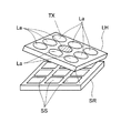
図3を参照して、個眼光学系が平面状に並ぶ複眼光学系LHが傾いたときには、複眼光学系LHが傾いても撮像領域との距離が実質的に一定である軸TXが存在する。本件明細書においては、この軸をチルト軸と呼ぶ。チルト軸TX上に複数の個眼光学系Laが存在する場合、それらのピント位置は、理論上は同じとなる。
そこで、図11において、複眼光学系LHを移動させつつ、全ての撮像領域からの画像信号を、評価値算出部CLにてフィルタ処理を行って、高周波成分を抽出したときに、チルト軸検出部TDが、同じ位置にピークを持つ画像信号を出力した複数の撮像領域を、対応する個眼撮像系がチルト軸TX上にあると推定し、システム制御部2に通知する。そして、これらの撮像領域をメモリ3に記憶することができる。こうして、フォーカス状態の判別時に選択されるべき複数の領域を予め決定しておくことにより、評価値を算出するべき画像信号を限定することができる。尚、実際の撮像時に用いる撮像領域は、対応する個眼撮像系がチルト軸TX上にあるうちの、更に中央撮像領域とすることが望ましい。
尚、個眼撮像系が常にチルト軸TX上にあるとは限らない。そこで、全ての撮像領域からの画像信号から高周波成分を抽出したときに、チルト軸検出部TDは、対応する個眼撮像系がチルト軸TXから近いと推定される撮像領域を選択し、これらの撮像領域をメモリ3に記憶することができる。
実際の撮像時には、選択された複数の撮像領域からの画像信号から得られた高周波成分に基づくフォーカス位置に関する評価値を加重平均して、仮想的にピント位置を求め、アクチュエータACTが複眼光学系LHを駆動することが好ましい。
図12は、変形例にかかる複眼光学系LHと撮像素子SRを模式的に示す斜視図である。複眼光学系LHの個眼光学系La及び撮像領域SSは4行4列に限らず、例えば、図12に示すように3行3列であっても良いし、図4に示したような5列(例えば、5行5列)であてもよい。
本発明は、本明細書に記載の実施形態に限定されるものではなく、他の実施形態・変形例を含むことは、本明細書に記載された実施形態や技術思想から本分野の当業者にとって明らかである。例えば、撮像装置の組み付け後の検査時に、撮像領域を選択することに限らず、定期的に、例えば、撮像装置の電源ON時に毎回、撮像領域を選択するようにしても良い。
また、メモリ3に記憶される情報は、予め、指定された特定の個眼光学系に対応する前記領域を示す情報であってもよい。この場合も、メモリ3が、複数の前記領域を示す情報を記憶していてもよく、フォーカス調整を行う際に、メモリ3に記憶された情報に基づいて、複数の領域の中から前記複眼光学系LHの中心に近い少なくともの一つの領域を選択し、選択された領域が一つの場合はその領域からの画像信号から抽出したフォーカス位置に関する評価値に基づいて駆動素子を駆動し、選択された前記領域が複数の場合はそれらの加重平均値に基づいて駆動素子を駆動するようにしてもよい。
また、撮像装置に表示部を設け、複眼光学系のフォーカス状態を使用者に報知するようにしてもよい。そして、使用者が表示内容に基づいて手動で撮像素子に対する複眼光学系の位置を変更するようにしてもよい。
1 画像処理部
1a 画像合成部
1b 画像補正部
3 メモリ
10 制御回路
LA1 レンズアレイ
LA2 レンズアレイ
La 個眼光学系
LH 複眼光学系
LU 撮像ユニット
SR 撮像素子
SS 撮像面(撮像領域)
CL 評価値算出部
CT システム制御部
ACT アクチュエータ
1a 画像合成部
1b 画像補正部
3 メモリ
10 制御回路
LA1 レンズアレイ
LA2 レンズアレイ
La 個眼光学系
LH 複眼光学系
LU 撮像ユニット
SR 撮像素子
SS 撮像面(撮像領域)
CL 評価値算出部
CT システム制御部
ACT アクチュエータ
Claims (13)
- 並列的に配置された複数の個眼光学系を備え一体的に構成された複眼光学系と、
各個眼光学系により光学像がそれぞれ結像される複数の領域を備え、前記領域に結像される光学像を画像信号に変換する撮像素子と、
前記撮像素子に対して、前記複眼光学系を光軸方向に相対的に移動可能に支持する支持部材と、
前記画像信号に基づいて、前記個眼光学系のフォーカス状態を表す評価値を算出する評価値算出部を含む制御回路と、を有し、
前記制御回路は、前記複数の領域からそれらよりも少ない数の少なくとも一つの前記領域を選択し、選択された少なくとも一つの前記領域からの画像信号の評価値に基づいて、前記複眼光学系のフォーカス状態を判別することを特徴とする画像入力装置。 - 生成する画像信号から前記評価値が算出されるべき少なくとも一つの前記領域を示す情報を記憶するメモリをさらに備え、
前記制御回路は、前記メモリに記憶された前記情報に基づいて、少なくとも一つの前記領域を選択することを特徴とする請求項1に記載の画像入力装置。 - 前記支持部材は、駆動素子を有し、該駆動素子の駆動によって前記複眼光学系を光軸方向に移動させるものであり、
前記制御回路は、選択された少なくとも一つの前記領域からの画像信号に基づいて算出された前記評価値に基づいて前記駆動素子を駆動して前記複眼光学系のフォーカス調整を行うことを特徴とする請求項2に記載の画像入力装置。 - 前記制御回路は、予め、前記駆動素子を駆動して前記複眼光学系と前記撮像素子との間の距離を変更しつつ、前記評価値算出部により、前記複数の領域からの画像信号から抽出した高周波成分に基づいて、各個眼光学系と、それに対応する前記領域とが最適なフォーカス位置となるときの、前記複眼光学系の基準部位と前記撮像素子との間の距離である最適光軸方向距離に対応する情報をそれぞれ求め、複数の前記最適光軸方向距離の中央値に最も近い前記情報を示す前記個眼光学系に対応する前記領域を選択し、その領域を示す情報を前記メモリに記憶することを特徴とする請求項3に記載の画像入力装置。
- 前記制御回路は、予め、前記駆動素子を駆動して前記複眼光学系と前記撮像素子との間の距離を変更しつつ、前記評価値算出部により、前記複数の領域からの画像信号から抽出した高周波成分に基づいて、各個眼光学系と、それに対応する前記領域とが最適なフォーカス位置となるときの、前記複眼光学系の基準部位と前記撮像素子との間の距離である最適光軸方向距離に対応する情報をそれぞれ求め、複数の前記最適光軸方向距離の中央値に近い情報を示す前記個眼光学系に対応する前記領域を複数個選択し、それらの領域を示す情報を前記メモリに記憶し、フォーカス調整を行う際には、前記メモリに記憶された複数の前記領域からの画像信号に基づいて算出された複数の前記評価値の加重平均値に基づいて、前記駆動素子を駆動することを特徴とする請求項3に記載の画像入力装置。
- 前記制御回路は、予め、前記駆動素子を駆動して前記複眼光学系と前記撮像素子との間の距離を変更しつつ、前記評価値算出部により、前記複数の領域からの画像信号から抽出した高周波成分に基づいて、前記撮像素子に対する前記複眼光学系の距離が異なる複数の位置において各領域に対応する前記個眼光学系のピント位置のずれ量に対応する情報を求め、求めた該情報に基づいて前記ピント位置の最大ずれ量が最小となる位置を特定し、該位置において、前記ピント位置のずれ量が最小となる前記個眼光学系に対応する前記領域を選択し、その領域を示す情報を前記メモリに記憶することを特徴とする請求項3に記載の画像入力装置。
- 前記制御回路は、予め、前記駆動素子を駆動して前記複眼光学系と前記撮像素子との間の距離を変更しつつ、前記評価値算出部により、前記複数の領域からの画像信号から抽出した高周波成分に基づいて、前記撮像素子に対する前記複眼光学系の距離が異なる複数の位置において各領域に対応する前記個眼光学系のピント位置のずれ量に対応する情報を求め、求めた該情報に基づいて前記ピント位置の最大ずれ量が最小となる位置を特定し、該位置において、前記ピント位置のずれ量が最小となる前記個眼光学系に対応する前記領域を複数個選択し、それらの領域を示す情報を前記メモリに記憶し、フォーカス調整を行う際には、前記メモリに記憶された複数の前記領域からの画像信号に基づいて算出された複数の前記評価値の加重平均値に基づいて、前記駆動素子を駆動することを特徴とする請求項3に記載の画像入力装置。
- 前記制御回路は、前記複数の領域からの画像信号から抽出した高周波成分に基づいて、前記複眼光学系のチルト軸を求めるチルト軸検出部をさらに有し、予め、前記チルト軸検出部により求めた前記チルト軸上に位置する前記個眼光学系に対応する前記領域を選択し、その領域を示す情報を前記メモリに記憶することを特徴とする請求項2に記載の画像入力装置。
- 前記制御回路は、前記複数の領域からの画像信号から抽出した高周波成分に基づいて、前記複眼光学系のチルト軸を求めるチルト軸検出部をさらに有し、予め、前記チルト軸検出部により求めた前記チルト軸に最も近い前記個眼光学系に対応する前記領域を選択し、その領域を示す情報を前記メモリに記憶することを特徴とする請求項2に記載の画像入力装置。
- 前記メモリに記憶される情報は、予め、指定された特定の個眼光学系に対応する前記領域を示す情報である請求項2に記載の画像入力装置。
- 前記メモリは、複数の前記領域を示す情報を記憶しており、前記制御回路は、前記複眼光学系のフォーカス調整を行う際には、前記メモリに記憶された情報に基づいて、複数の前記領域の中から前記複眼光学系の中心に近い少なくともの一つの前記領域を選択し、選択された前記領域が一つの場合はその領域からの画像信号に基づいて算出された前記評価値に基づいて、前記駆動素子を駆動し、選択された前記領域が複数の場合はそれらの領域からの画像信号に基づいて算出された複数の前記評価値の加重平均値に基づいて、前記駆動素子を駆動することを特徴とする請求項3、4、6のいずれかに記載の画像入力装置。
- 前記複眼光学系は、平面状に並ぶ複数のレンズを一体成形したレンズアレイを有することを特徴とする請求項1~11のいずれかに記載の画像入力装置。
- 並列的に配置された複数の個眼光学系を備え一体的に構成された複眼光学系と、各個眼光学系により光学像がそれぞれ結像される複数の領域を備え、前記領域に結像された光学像を画像信号に変換する撮像素子と、前記複眼光学系を前記撮像素子に対して光軸方向に相対的に移動可能に支持する支持部材と、を備える画像入力装置のフォーカス判別方法において、
前記複数の領域からそれよりも少ない数の少なくとも一つの前記領域を選択し、
選択された少なくとも一つの前記領域からの画像信号に基づいて、フォーカス状態を表す評価値を算出し、算出された評価値に基づいて、前記複眼光学系のフォーカス状態を判別することを特徴とする画像入力装置のフォーカス判別方法。
Priority Applications (1)
| Application Number | Priority Date | Filing Date | Title |
|---|---|---|---|
| JP2015521444A JPWO2014196511A1 (ja) | 2013-06-05 | 2014-06-03 | 画像入力装置 |
Applications Claiming Priority (2)
| Application Number | Priority Date | Filing Date | Title |
|---|---|---|---|
| JP2013118831 | 2013-06-05 | ||
| JP2013-118831 | 2013-06-05 |
Publications (1)
| Publication Number | Publication Date |
|---|---|
| WO2014196511A1 true WO2014196511A1 (ja) | 2014-12-11 |
Family
ID=52008152
Family Applications (1)
| Application Number | Title | Priority Date | Filing Date |
|---|---|---|---|
| PCT/JP2014/064679 Ceased WO2014196511A1 (ja) | 2013-06-05 | 2014-06-03 | 画像入力装置 |
Country Status (2)
| Country | Link |
|---|---|
| JP (1) | JPWO2014196511A1 (ja) |
| WO (1) | WO2014196511A1 (ja) |
Cited By (2)
| Publication number | Priority date | Publication date | Assignee | Title |
|---|---|---|---|---|
| JPWO2016158184A1 (ja) * | 2015-03-31 | 2018-02-01 | ソニー株式会社 | 医療用観察装置、レンズ駆動制御装置、レンズ駆動制御方法、プログラム、及びビデオ顕微鏡装置 |
| CN116296273A (zh) * | 2021-12-21 | 2023-06-23 | 成都极米科技股份有限公司 | 多复眼元件对准方法、系统、装置、计算机设备及介质 |
Citations (4)
| Publication number | Priority date | Publication date | Assignee | Title |
|---|---|---|---|---|
| JP2002243908A (ja) * | 2001-02-13 | 2002-08-28 | Minolta Co Ltd | 赤外線用光学素子および赤外線カメラ |
| JP2009115893A (ja) * | 2007-11-02 | 2009-05-28 | Canon Inc | 撮像装置 |
| JP2011234173A (ja) * | 2010-04-28 | 2011-11-17 | Panasonic Corp | 撮像装置 |
| JP2012138386A (ja) * | 2010-12-24 | 2012-07-19 | Nikon Corp | 撮像素子モジュール、撮像装置およびマイクロレンズモジュール |
-
2014
- 2014-06-03 WO PCT/JP2014/064679 patent/WO2014196511A1/ja not_active Ceased
- 2014-06-03 JP JP2015521444A patent/JPWO2014196511A1/ja active Pending
Patent Citations (4)
| Publication number | Priority date | Publication date | Assignee | Title |
|---|---|---|---|---|
| JP2002243908A (ja) * | 2001-02-13 | 2002-08-28 | Minolta Co Ltd | 赤外線用光学素子および赤外線カメラ |
| JP2009115893A (ja) * | 2007-11-02 | 2009-05-28 | Canon Inc | 撮像装置 |
| JP2011234173A (ja) * | 2010-04-28 | 2011-11-17 | Panasonic Corp | 撮像装置 |
| JP2012138386A (ja) * | 2010-12-24 | 2012-07-19 | Nikon Corp | 撮像素子モジュール、撮像装置およびマイクロレンズモジュール |
Cited By (2)
| Publication number | Priority date | Publication date | Assignee | Title |
|---|---|---|---|---|
| JPWO2016158184A1 (ja) * | 2015-03-31 | 2018-02-01 | ソニー株式会社 | 医療用観察装置、レンズ駆動制御装置、レンズ駆動制御方法、プログラム、及びビデオ顕微鏡装置 |
| CN116296273A (zh) * | 2021-12-21 | 2023-06-23 | 成都极米科技股份有限公司 | 多复眼元件对准方法、系统、装置、计算机设备及介质 |
Also Published As
| Publication number | Publication date |
|---|---|
| JPWO2014196511A1 (ja) | 2017-02-23 |
Similar Documents
| Publication | Publication Date | Title |
|---|---|---|
| EP3158723B1 (en) | Autofocus for folded optic array cameras | |
| CN112740650B (zh) | 摄像装置设备 | |
| US9083880B2 (en) | Imaging device, semiconductor integrated circuit, and imaging method | |
| US9344617B2 (en) | Image capture apparatus and method of controlling that performs focus detection | |
| JP2009015164A (ja) | 撮像装置 | |
| KR20180044085A (ko) | 카메라 모듈 및 이를 포함하는 전자 기기 | |
| KR20180046624A (ko) | 이미지 합성용 보정데이터를 획득하는 듀얼카메라 모듈 제조방법 및 장치 그리고 이에 의해 제조된 듀얼카메라 모듈 | |
| US10735655B2 (en) | Apparatus, method, and program for image processing | |
| CN106412419B (zh) | 摄像设备及其控制方法 | |
| WO2014196511A1 (ja) | 画像入力装置 | |
| JPWO2014203844A1 (ja) | 画像入力装置 | |
| Ben-Ezra | A digital gigapixel large-format tile-scan camera | |
| JP2016134857A (ja) | 撮像装置及びその制御方法、プログラム、記憶媒体 | |
| JP2009033607A (ja) | 撮像装置および画像処理方法 | |
| JP2017201810A (ja) | 撮像装置及び撮像方法 | |
| JP2013061560A (ja) | 測距装置および撮像装置 | |
| US12238260B2 (en) | Device, capturing device, control method, and storage medium operable for outputting pair of captured images pertaining to binocular stereopsis | |
| US11095817B2 (en) | Apparatus and method for image processing and storage medium for processing captured images | |
| JP2016004152A (ja) | 撮像装置および撮像方法 | |
| JP5973784B2 (ja) | 撮像装置及びその制御方法、プログラム、並びに記憶媒体 | |
| CN112272944B (zh) | 相机装置校准方法 | |
| JP2012134826A (ja) | 撮像装置 | |
| KR20170102755A (ko) | 라이트필드 카메라용 오토포커싱 장치 및 그 방법 | |
| JP7504579B2 (ja) | 撮像装置、撮像装置の制御方法およびプログラム | |
| CN115866373B (zh) | 具音圈马达的自动对齐的对焦结构 |
Legal Events
| Date | Code | Title | Description |
|---|---|---|---|
| 121 | Ep: the epo has been informed by wipo that ep was designated in this application |
Ref document number: 14807312 Country of ref document: EP Kind code of ref document: A1 |
|
| ENP | Entry into the national phase |
Ref document number: 2015521444 Country of ref document: JP Kind code of ref document: A |
|
| NENP | Non-entry into the national phase |
Ref country code: DE |
|
| 122 | Ep: pct application non-entry in european phase |
Ref document number: 14807312 Country of ref document: EP Kind code of ref document: A1 |