WO2014196184A1 - Automatic bread machine - Google Patents
Automatic bread machine Download PDFInfo
- Publication number
- WO2014196184A1 WO2014196184A1 PCT/JP2014/002910 JP2014002910W WO2014196184A1 WO 2014196184 A1 WO2014196184 A1 WO 2014196184A1 JP 2014002910 W JP2014002910 W JP 2014002910W WO 2014196184 A1 WO2014196184 A1 WO 2014196184A1
- Authority
- WO
- WIPO (PCT)
- Prior art keywords
- bread
- heater
- container
- bread container
- rotating shaft
- Prior art date
Links
Images


Classifications
-
- A—HUMAN NECESSITIES
- A21—BAKING; EDIBLE DOUGHS
- A21B—BAKERS' OVENS; MACHINES OR EQUIPMENT FOR BAKING
- A21B7/00—Baking plants
- A21B7/005—Baking plants in combination with mixing or kneading devices
-
- A—HUMAN NECESSITIES
- A21—BAKING; EDIBLE DOUGHS
- A21C—MACHINES OR EQUIPMENT FOR MAKING OR PROCESSING DOUGHS; HANDLING BAKED ARTICLES MADE FROM DOUGH
- A21C1/00—Mixing or kneading machines for the preparation of dough
- A21C1/02—Mixing or kneading machines for the preparation of dough with vertically-mounted tools; Machines for whipping or beating
-
- A—HUMAN NECESSITIES
- A21—BAKING; EDIBLE DOUGHS
- A21C—MACHINES OR EQUIPMENT FOR MAKING OR PROCESSING DOUGHS; HANDLING BAKED ARTICLES MADE FROM DOUGH
- A21C1/00—Mixing or kneading machines for the preparation of dough
- A21C1/14—Structural elements of mixing or kneading machines; Parts; Accessories
- A21C1/1495—Arrangements for cooling or heating ; Arrangements for applying super- or sub-atmospheric pressure
-
- B—PERFORMING OPERATIONS; TRANSPORTING
- B01—PHYSICAL OR CHEMICAL PROCESSES OR APPARATUS IN GENERAL
- B01F—MIXING, e.g. DISSOLVING, EMULSIFYING OR DISPERSING
- B01F27/00—Mixers with rotary stirring devices in fixed receptacles; Kneaders
- B01F27/80—Mixers with rotary stirring devices in fixed receptacles; Kneaders with stirrers rotating about a substantially vertical axis
- B01F27/808—Mixers with rotary stirring devices in fixed receptacles; Kneaders with stirrers rotating about a substantially vertical axis with stirrers driven from the bottom of the receptacle
-
- B—PERFORMING OPERATIONS; TRANSPORTING
- B01—PHYSICAL OR CHEMICAL PROCESSES OR APPARATUS IN GENERAL
- B01F—MIXING, e.g. DISSOLVING, EMULSIFYING OR DISPERSING
- B01F35/00—Accessories for mixers; Auxiliary operations or auxiliary devices; Parts or details of general application
- B01F35/90—Heating or cooling systems
- B01F35/92—Heating or cooling systems for heating the outside of the receptacle, e.g. heated jackets or burners
-
- B—PERFORMING OPERATIONS; TRANSPORTING
- B01—PHYSICAL OR CHEMICAL PROCESSES OR APPARATUS IN GENERAL
- B01F—MIXING, e.g. DISSOLVING, EMULSIFYING OR DISPERSING
- B01F35/00—Accessories for mixers; Auxiliary operations or auxiliary devices; Parts or details of general application
- B01F35/90—Heating or cooling systems
- B01F2035/99—Heating
Definitions
- the present invention relates to an automatic bread maker generally used for home use.
- a commercially available automatic bread maker for home use it is common to produce bread by sequentially performing a kneading process, a fermentation process, and a baking process.
- a kneading step a bread container containing flour, water, yeast and other bread ingredients is placed in a baking chamber in the main body, and the bread ingredients in the bread container are kneaded by kneading means such as blades.
- the kneaded bread dough is expanded by yeast fermentation.
- the baking process the baked dough is heated, and the bread dough is baked into bread using the bread container as it is as a baking mold.
- Patent Document 1 As this type of automatic bread maker, those having various structures are known (for example, see Patent Document 1).
- a communication opening is provided in the bread mold table to allow communication between the baking room space and the bread mold table space.
- the bread-type table space is heated by the communication opening. As a result, temperature unevenness of the bread container is suppressed, heating is performed uniformly, and improvement of the bread quality is achieved.
- an object of the present invention is to provide an automatic bread maker that solves the above-described problems and can simultaneously improve the quality of bread and ensure the reliability of the automatic bread maker.
- the present invention is configured as follows.
- An automatic bread maker includes a bread container that is detachably mounted in a baking chamber, A tubular protrusion protruding from the bottom of the bread container to the outside of the bread container; A rotating shaft extending through the bottom of the bread container from the inside to the outside of the bread container and extending to the inside of the protrusion; A bearing that rotatably supports the rotating shaft on the bread container; Bread blades engaged with the rotating shaft in the bread container; A first heater disposed below the bottom of the bread container and outside the protrusion in the baking chamber; A second heater disposed above the first heater in the firing chamber; A controller that controls energization of the first and second heaters, The protrusion functions as a heat shield between the rotating shaft and the bearing and the first heater when disposed on the bottom of the firing chamber.
- the automatic bread maker of the present invention can achieve both improvement in bread quality and ensuring the reliability of the automatic bread maker.
- FIG. 4A Longitudinal sectional view of the automatic bread maker in the first embodiment
- Vertical sectional view of an automatic bread maker in a third embodiment 1 is a longitudinal sectional view showing a bread container and a protruding portion of an automatic bread maker according to first to third embodiments.
- the fermentation process is performed at a temperature of 30 to 40 ° C.
- the temperature is raised to around 200 ° C. Since fermentation and baking are performed in the same baking chamber, preheating before a baking process cannot be performed. Therefore, the temperature rise of the bread container and bread dough in the baking process is slow.
- the baking chamber is an oven made of metal, the bread dough in the bread container is uniformly heated in the baking process, and the bread dough can be baked evenly.
- the rotary shaft is provided in the vicinity of the bottom of the bread container, so that the rotary shaft may be excessively heated. If the rotating shaft is exposed to an overheated state, the rotating shaft and the bearing may be damaged, and rotation of the pan blades may be hindered. In addition, there is a possibility that water, which is a raw material for bread, leaks from between the damaged rotating shaft and bearing.
- a bread container detachably mounted in the baking chamber;
- a tubular protrusion protruding from the bottom of the bread container to the outside of the bread container;
- a rotating shaft extending through the bottom of the bread container from the inside to the outside of the bread container and extending to the inside of the protrusion;
- a bearing that rotatably supports the rotating shaft on the bread container;
- a first heater disposed below the bottom of the bread container and outside the protrusion in the baking chamber;
- a second heater disposed above the first heater in the firing chamber;
- a controller that controls energization of the first and second heaters,
- the protrusion provides an automatic bread maker that functions as a heat shield between the rotating shaft and the bearing and the first heater when disposed on the bottom of the baking chamber.
- the firing chamber by providing two heaters in the firing chamber, it is possible to perform more flexible heating than when one heater is provided.
- the first heater below the bottom of the bread container in the baking chamber, the bottom of the bread container can be intensively heated. This makes it possible to intensively heat the lower part of the bread dough, particularly when creating a hard bread, and improve the quality of the bread.
- the protrusion has a function of shielding heat between the rotating shaft and the bearing and the first heater, the influence of the heat of the first heater on the rotating shaft and the bearing can be reduced. Thereby, the reliability of an automatic bread maker can be improved. That is, it is possible to achieve both improvement in the quality of bread and ensuring the reliability of the automatic bread maker.
- the automatic bread maker according to the first aspect, wherein the protrusion includes a heat insulating layer between the rotary shaft and the bearing and the first heater.
- the protrusion includes a tubular inner cylinder and an outer cylinder disposed on the inner side and the outer side with a space therebetween,
- the heat insulating layer of the protruding portion provides the automatic bread maker according to the second aspect, which is formed in a space between the inner cylinder and the outer cylinder.
- the automatic bread maker according to the second aspect or the third aspect, wherein the heat insulating layer is an air layer.
- the thermal conductivity of the protrusion is lower than the thermal conductivity of the bread container.
- the automatic bread maker according to any one of the first to fifth aspects, further comprising a cooling device for cooling the rotating shaft.
- the material of the outer surface of the protruding portion has an infrared reflectance higher than that of the material of the bread container, and is manufactured automatically according to any one of the first to sixth aspects. Provide bread machine.
- the bottom portion of the bread container facing the first heater is coated with a material having a higher infrared absorption rate than the material of the bread container.
- a reflecting plate disposed around the first heater so as to reflect heat of the first heater toward the bottom of the bread container.
- a rotation mechanism for rotating the rotation shaft is A motor for generating a rotational driving force for the rotational shaft; A drive connector disposed at the bottom of the firing chamber and driven by the motor; A driven connector attached to the rotating shaft and connected to the drive connector to be driven;
- the automatic bread maker according to any one of the first to ninth aspects, wherein the rotational driving force by the motor is transmitted to the rotation shaft via the drive connector and the driven connector.
- the controller starts energizing the second heater after energizing the first heater in the baking step of heating and baking the dough.
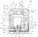
- the automatic bread maker 50 includes a main body 1, a baking chamber 17, a heater 4, and an internal temperature sensor 16.
- the main body 1 has a bottomed cylindrical shape, and is formed of resin in the first embodiment.
- the firing chamber 17 is provided in the main body 1 and is made of sheet metal in the first embodiment.
- the heater 4 is a heater that heats the inside of the firing chamber 17.
- the heater 4 includes a first heater 4a and a second heater 4b. Both the first heater 4 a and the second heater 4 b are disposed in the baking chamber 17.
- the first heater 4a is disposed below the second heater 4b.
- the internal temperature sensor 16 is a sensor that detects the temperature in the baking chamber 17.
- the automatic bread maker 50 further includes the bread container 2, the rotating shaft 6, the bearing 41, the bread blade 5, and the driven connector 14.
- the bread container 2 is a container having a bottomed cylindrical shape, and includes a cylinder portion 2a on the upper side and a bottom portion 2b on the lower side.
- the cylinder part 2a has a cylindrical shape extending in the vertical direction.
- the bottom 2b is a part constituting the bottom of the bread container 2 and extends from the lower end of the cylindrical part 2a so as to be partially curved, and is formed so as to extend in the horizontal direction and close the bottom of the bread container 2.
- the bottom portion 2b of the bread container 2 includes a curved portion that is curved from the connection portion 2c with the cylindrical portion 2a, and a horizontal portion that extends substantially horizontally from the curved portion. That is, the bottom portion 2b of the bread container 2 includes not only a horizontal portion that is located at the bottom of the bread container 2 and extends substantially horizontally, but also a curved portion that is curved to continue to the horizontal portion.
- the connection part 2c is located in the boundary of the part (cylinder part 2a) extended in the perpendicular direction in the bread container 2, and the curved part. Further, the bread container 2 is formed with a convex portion 2d protruding inward.
- the convex portion 2d is formed at a position straddling the cylindrical portion 2a and the bottom portion 2b.
- the bread container 2 can be detachably installed in the baking chamber 17. That is, the bread container 2 is detachably mounted in the baking chamber 17.
- FIG. 1 shows a state in which the bread container 2 is attached in the baking chamber 17, that is, a state in which the bread container 2 is arranged on the bottom in the baking chamber 17.
- the bread container 2 is formed of aluminum.
- the rotation shaft 6 is a shaft provided so as to penetrate from the inside to the outside of the bread container 2 at the bottom 2 b of the bread container 2.
- the rotating shaft 6 is rotatably supported by the bread container 2 by a bearing 41.
- the rotating shaft 6 extends to the inside of a protrusion 40 described later.
- the bearing 41 is configured integrally with the bread container 2.
- the bread blade 5 is a blade for kneading the bread dough 31 in the bread container 2.
- the pan blade 5 can be detachably fitted (engaged) with the rotary shaft 6. When the pan blade 5 is fitted to the rotary shaft 6, it rotates with the rotation of the rotary shaft 6.
- a driven connector 14 is integrally attached to the rotating shaft 6.
- the driven connector 14 is disposed outside the bread container 2 and is driven by being connected to a drive connector 13 described later.
- the pan blade 5 includes a blade bearing portion 5c and a flat plate portion 5d.
- the blade bearing portion 5 c is a bearing that is fitted to the rotary shaft 6.
- the flat plate portion 5d is a kneading blade plate attached to the blade bearing portion 5c.
- the flat plate portion 5d protrudes from the outer peripheral surface of the blade bearing portion 5c in a direction perpendicular to the axial direction of the rotary shaft 6. As shown in FIG. 1, in the state where the bread container 2 is installed in the baking chamber 17, the flat plate portion 5d extends in the horizontal direction from the outer peripheral surface of the blade bearing portion 5c.
- the automatic bread maker 50 further includes a protrusion 40.
- the protrusion 40 is a member that protrudes from the bottom 2 b of the bread container 2 to the outside of the bread container 2, and is disposed so as to cover the rotating shaft 6 and the bearing 41.
- the protrusion 40 is configured integrally with the bread container 2, and is formed of aluminum which is the same material as the bread container 2 in the first embodiment.
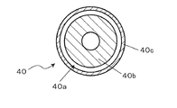
- the protrusion 40 has a double pipe structure so as to form an air layer 40a that is a heat insulating layer.
- the specific structure of the protrusion 40 will be described later with reference to FIGS. 4A and 4B.
- the formation of the air layer 40a which is a heat insulating layer, suppresses heat transfer from the firing chamber 17 to the rotating shaft 6 and the bearing 41.
- the protrusion part 40 since the protrusion part 40 has a function which shields the rotating shaft 6 and the bearing 41, it is also called a "heat shield part.”
- the first heater 4 a is disposed in the baking chamber 17 below the bottom 2 b of the bread container 2 and outside the protruding portion 40. That is, the first heater 4a is disposed on the opposite side (that is, the outer side) of the protruding portion 40 from the inner side where the rotating shaft 6 and the bearing 41 are disposed.
- the first heater 4a in the first embodiment is disposed inside the bread container 2 when viewed from above. That is, it does not protrude outside the bread container 2.
- the 2nd heater 4b in 1st Embodiment is arrange
- the automatic bread maker 50 further includes a rotation mechanism that rotates the rotation shaft 6.
- a motor 7, a small pulley 11, a large pulley 12, and a drive connector 13 are provided as a rotation mechanism.
- the motor 7 is a motor that generates a rotational driving force for the rotating shaft 6.
- the small pulley 11 is a pulley that is integrally attached to the drive shaft of the motor 7.
- the large pulley 12 is a pulley attached integrally with the drive connector 13.
- the small pulley 11 and the large pulley 12 are connected to each other by a belt 15.
- the rotation operation of the motor 7 is transmitted to the drive connector 13 through the small pulley 11, the belt 15, and the large pulley 12.
- the drive connector 13 is driven by the motor 7.
- the drive connector 13 is disposed at the bottom of the baking chamber 17.
- the driven connector 14 on the bread container 2 side is fitted and connected to the drive connector 13 on the baking chamber 17 side. Thereby, the rotation operation of the motor 7 is transmitted to the driven connector 14 via the drive connector 13.
- the driven connector 14 rotates, the rotating shaft 6 rotates and the bread blades 5 in the bread container 2 can be rotated.
- the rotating mechanism that rotates the rotating shaft 6 includes at least the motor 7, the drive connector 13, and the driven connector 14.
- the rotational driving force by the motor 7 is transmitted to the rotating shaft 6 via the drive connector 13 and the driven connector 14.
- the automatic bread maker 50 further includes a lid 3, an inner lid 21, an ingredient storage container 20, a solenoid 10, a yeast storage section 24, and a yeast throwing means 25.
- the lid 3 includes a lower lid 3a and an upper lid 3b. Both the lower lid 3a and the upper lid 3b are made of resin.
- the inner lid 21 is engaged with and fixed to the lower lid 3 a so as to cover the upper portion of the main body 1.
- the ingredient storage container 20 is a container for automatically charging raisins and nuts.
- the ingredient storage container 20 can be detachably fixed to the inner lid 21 and the lower lid 3a.
- the ingredient storage container 20 includes a container lid 20a, a container lid opening means 20b, and a container body 20c.
- the container lid 20a is rotatably connected to the container body 20c.
- the container lid opening means 20b fixes the container lid 20a in a closed state.
- the container lid 20a constitutes a part of the inner lid 21 in a closed state. At least the bottom of the container lid 20a is made of metal.
- a solenoid 10 is disposed in the main body 1.
- the solenoid 10 includes a cylinder 10a and a rod 10b.
- the cylinder 10a supports the rod 10b.
- the solenoid 10 operates the operation of the container lid opening means 20b by operating the operation of the rod 10b. By this operation, the container lid 20a is interlocked between a closed state and an opened state with respect to the container body 20c.
- the yeast storage unit 24 is a member for automatically charging dry yeast, and is provided on the lower lid 3a.
- the yeast throwing means 25 holds the yeast in the yeast storage portion 24 by being pressed against the inner lid 21.
- the yeast is automatically charged into the bread container 2 when the yeast charging means 25 is separated from the inner lid 21.
- the atmospheric temperature in the baking chamber 17 becomes a high temperature of 150 to 230 ° C., for example, due to the heating of the heater 4.
- the surface of the inner lid 21 also has a high temperature of about 150 to 230 ° C.
- the surface of the outer lid 3a also has a temperature of about 60 to 90 ° C. In this way, the entire lid including the outer lid 3a and the inner lid 21 is heated.
- the solenoid 10 is disposed in such a lid, the solenoid 10 becomes high temperature in the firing process, and there may be a problem due to an increase in the temperature of the coil wire or the lead wire (insulation deterioration or the like).
- the solenoid 10 since the solenoid 10 is disposed in the main body 1, the temperature of the solenoid 10 is not easily increased. Therefore, the reliability of the solenoid 10 can be improved.
- the lid 3 is attached to the main body 1 through a hinge 22 so as to be opened and closed. Therefore, when the lid 3 is closed, the inner lid 21 hits the main body 1, and the inner lid 21 receives impact and vibration from the main body 1.
- the solenoid 10 which is a heavy component of about 100 g
- the solenoid 10 is arrange
- according to the structure of 1st Embodiment compared with the case where the solenoid 10 is arrange
- the upper lid 3b is rotatably connected to the lower lid 3a via a hinge 23.
- Such an upper lid 3b has a role of preventing leakage of steam in the baking process.
- the ingredient storage container 20 has a form in which the upper side is closed and cannot be opened, but it may be opened upward. In this case, even when the ingredient storage container 20 is mounted on the lid 3, the ingredient can be stored in the ingredient storage container 20 by opening the upper lid 3 b.
- the user puts hard bread materials such as flour, water, and salt into the bread container 2. Ingredients are pre-weighed by the user with reference to the recipe. After putting the material, the user puts dry yeast in the yeast storage unit 24 and operates the operation input display unit 9 to select a menu. According to the selected menu, the automatic bread maker 50 executes the bread making process.
- hard bread materials such as flour, water, and salt
- Ingredients are pre-weighed by the user with reference to the recipe.
- the user puts dry yeast in the yeast storage unit 24 and operates the operation input display unit 9 to select a menu. According to the selected menu, the automatic bread maker 50 executes the bread making process.
- the control unit 8 drives the motor 7 to rotate the bread blade 5.
- the bread dough 31 is kneaded by the rotation of the bread blades 5. That is, the kneading process is started. Due to the rotation of the bread blades 5, the flour and water are mixed to form an integral dough 31.
- the integrated bread dough 31 is pressed against the convex portion 2 d of the wall surface of the bread container 2 by the rotation of the bread blade 5.
- the bread dough 31 receives a pressing force from the wall surface of the bread container 2. Part of the bread dough 31 pressed against the wall surface of the bread container 2 adheres to the wall surface of the bread container 2 due to viscosity. In this state, the bread blade 5 rotates the bread dough 31, whereby a tensile force is applied to the bread dough 31.
- control unit 8 After forming gluten in the bread dough 31 to some extent, the control unit 8 operates the yeast throwing means 25 to throw yeast into the bread container 2.
- the control unit 8 After the bread dough 31 is laid for a predetermined time, the control unit 8 operates the bread blade 5 again. Thus, physical pressing force and tensile force are applied to the bread dough 31 while kneading the yeast uniformly into the bread dough 31.
- the gluten network in the bread dough 31 can grow to form the bread dough 31 with appropriate elasticity and extensibility. When such bread dough 31 is formed, the kneading process is completed.
- the automatic bread maker 50 performs a fermentation process to ferment the dough 31.
- the control unit 8 energizes the first heater 4a and / or the second heater 4b to heat the inside of the baking chamber 17. After the start of heating, the controller 8 controls the temperature so that the temperature detected by the internal temperature sensor 16 becomes a predetermined fermentation temperature. That is, the energization of the heater 4 is controlled.
- the temperature control of the fermentation temperature may be performed by energizing only the first heater 4a without energizing the second heater 4b. Convective heat and radiant heat from the first heater 4 a are blocked by the bottom 2 b of the bread container 2. Therefore, according to the control for energizing only the first heater 4a, the lower space of the baking chamber 17 is easily heated, while the upper space of the baking chamber 17 is hardly heated. Thereby, the direct heating amount from the upper part of the bread dough 31 decreases. That is, drying and hardening of the bread dough 31 due to heating can be prevented. By preventing the bread dough 31 from drying and curing, the extensibility of the bread dough 31 can be improved and the bread making performance can be improved.
- the bread dough 31 is fermented under appropriate fermentation temperature conditions.
- the yeast is activated, consuming starch-derived sugar and generating carbon dioxide and alcohol.
- countless bubbles are included in the bread dough 31, and the flavor of the bread dough 31 is improved.
- the gluten network of the dough 31 relaxes and loses elasticity. Therefore, the amount of carbon dioxide gas is appropriately reduced by degassing. Thereby, the network of gluten can be tensioned again and the activity of the yeast in the bread dough 31 can be increased.
- the degassing is performed by the control unit 8 operating the pan blade 5.
- the bread dough 31 is wound with a rotational force that does not tear the bread dough 31.
- the surface of the bread dough 31 is pulled, and the large bubbles in the bread dough 31 are crushed, thereby regaining the tension of the gluten network.
- the bread dough 31 can be made into the state which can endure further fermentation.
- the fermentation process is terminated when the final fermentation is completed.
- the automatic bread maker 50 performs a baking process to bake the dough 31.
- the control unit 8 starts energizing the second heater 4b after starting energizing the first heater 4a. That is, first, the control unit 8 does not energize the second heater 4b, but energizes only the first heater 4a adjacent to the bottom 2b of the bread container 2. As a result, the lower temperature of the bread dough 31 (the lower temperature of the bread dough 31 near the bottom 2b of the bread container 2) is rapidly increased.
- the inside of the firing chamber 17 was uniformly heated in the firing step.
- the upper temperature of the bread dough 31 (the temperature of the upper side of the bread dough 31 far from the bottom 2b of the bread container 2) rises in the same manner as the lower temperature of the bread dough 31. Therefore, in the case of a hard bread that does not contain fats and oils such as butter, drying and hardening are promoted in the upper part of the bread dough 31. Thereby, expansion
- the first heater 4a in the baking process, only the first heater 4a is first energized, so that the rise in the upper temperature of the bread dough 31 is slowed while heating the lower part of the bread dough 31 as the center. ing. Therefore, drying and hardening of the bread dough 31 surface can be suppressed.
- the yeast in the dough 31 since the lower temperature of the dough 31 is rapidly increased, the yeast in the dough 31 can be activated. Further, by generating water vapor inside the bread dough 31 by rapid temperature rise, the expansion of the bread dough 31 can be promoted by the action of the water vapor.
- the control unit 8 energizes the second heater 4b after a predetermined time has elapsed or when it is detected that the lower temperature of the bread dough 31 has sufficiently increased.
- the energization of the first heater 4a is stopped.
- the inside of the baking chamber 17 is uniformly heated by energizing the second heater 4b.
- the controller 8 controls the heating so that the temperature in the baking chamber 17 becomes a predetermined baking temperature. Thereby, the whole bread dough 31 can be baked uniformly.
- the baking process is terminated.
- the first heater 4a is disposed between the bottom 2b of the bread container 2 and the bottom of the baking chamber 17 at a position close to the protrusion 40. That is, the first heater 4 a is disposed in the vicinity of the rotating shaft 6 and the bearing 41 of the bread container 2. Therefore, in the firing step described above, when the first heater 4a is energized, the heat from the first heater 4a tends to be transmitted to the rotating shaft 6 and the bearing 41. This tendency of heat transfer in the firing chamber 17 is more conspicuous as compared to a configuration in which the lower heater is embedded in the bottom of the firing chamber and disposed outside the firing chamber as in Patent Document 1 described above.
- the protrusion part 40 when the protrusion part 40 is arrange
- the bearing 41 when the bearing 41 is a fluid bearing, it can prevent that a fluid flows out. In this way, the reliability of the automatic bread maker 50 can be improved and secured.
- the automatic bread maker 50 includes the first heater 4a and the second heater 4b disposed above the first heater 4a, so that flexible heating can be performed.
- the bottom 2b of the bread container 2 can be heated intensively. This makes it possible to rapidly heat the lower portion of the bread dough 31 particularly when making a hard bread, so that water vapor is generated inside the bread dough 31, and the water vapor forms a film between the bubbles in the bread dough 31. It can be broken and connected to form large bubbles. Due to the formation of such bubbles, the bread dough 31 can be greatly expanded and the fire passage inside the bread dough 31 can be improved. Therefore, the savory bread can be baked with good taste.
- the automatic bread maker 50 in the first embodiment it is possible to ensure both the reliability of the automatic bread maker 50 and the improvement of the bread quality.
- the protrusion part 40 is provided with the heat insulation layer (air layer 40a) between the rotating shaft 6, the bearing 41, and the 1st heater 4a.
- the heat insulation layer air layer 40a
- the thermal influence on the rotating shaft 6 and the bearing 41 by the first heater 4a can be further reduced. That is, the reliability of the automatic bread maker 50 can be improved.
- the air layer 40a is formed as a heat insulating layer in the protruding portion 40.
- the air layer 40a is filled only with air and is not filled with anything other than air. Thereby, reduction of manufacturing cost can also be aimed at, improving the heat insulation effect.
- a heat insulation layer in the protrusion part 40 when filling and forming heat insulating materials other than air, you may employ
- the material of the protruding portion 40 is the same aluminum as the material of the bread container 2, but is not limited to such a case, and may be other materials such as stainless steel, ceramic, and resin. .
- a material for example, a heat resistant resin
- the material having low thermal conductivity may be defined as a material having a thermal conductivity of 236 W / mK or less, which is the thermal conductivity of aluminum, for example.
- FIGS. 4A and 4B are longitudinal sectional views of the bread container 2 and the protrusion 40
- FIG. 4B is an A1-A1 sectional view of FIG. 4A (transverse section of the protrusion 40).
- the projecting portion 40 includes an inner cylinder 40b and an outer cylinder 40c.
- Both the inner cylinder 40 b and the outer cylinder 40 c are tubular members that extend downward from the bottom 2 b of the bread container 2.
- the inner cylinder 40b and the outer cylinder 40c are arranged at an interval from each other via the air layer 40a.
- the air layer 40a as a heat insulating layer is formed in a space between the inner cylinder 40b and the outer cylinder 40c.
- the inner cylinder 40b arranged on the inner side has a shape in which a cylindrical shape is partially missing. Specifically, as shown in FIG. 4A, a cylindrical gap is formed in three stages inside the inner cylinder 40b so as to increase in diameter from the top. These voids are all cylindrical and communicate with each other. As shown in FIG. 4A, the rotation shaft 6 is disposed in the upper gap. The rotary shaft 6 and the bearing 41 are disposed in the central gap. The rotating shaft 6 and the driven connector 14 are disposed in the lower gap.
- the outer cylinder 40c is a circular tubular member disposed around the inner cylinder 40b.
- a circular air layer 40a as shown in FIG. 4B is formed between the outer cylinder 40c and the inner cylinder 40b.
- the lower ends 40h of the inner cylinder 40b and the outer cylinder 40c are arranged in the same plane by being arranged at positions extending the same distance from the bottom 2b of the bread container 2. As shown in FIG. 4A, the lower end portion 40 h is positioned vertically downward from the lower end of the rotating shaft 6 and the driven connector 14 by a distance L. In such a configuration, when the bread container 2 is placed on a desk or the like, the protruding portion 40 functions as a pedestal.
- the protrusion part 40 since the protrusion part 40 has covered the rotating shaft 6 and the driven connector 14, it also has a function which protects the rotating shaft 6 and the driven connector 14 from a physical impact. In this case, if the material of the protrusion 40 is a hard material, the protective function can be further improved.
- the protrusion 40 not only has a function of a heat shield for the rotating shaft 6 and the bearing 41, but also at least a pedestal function of the bread container 2, and impact protection of the rotating shaft 5 and / or the driven connector 14. With functions.
- the structure of the automatic bread maker 50 can be made more compact and more efficient by providing the protrusion 40 with a plurality of functions.
- FIG. 2 is a longitudinal sectional view of an automatic bread maker 150 according to the second embodiment of the present invention.
- the automatic bread maker 150 in the second embodiment includes a cooling device for cooling the rotating shaft 6 and the bearing 41.
- a cooling device for cooling the rotating shaft 6 and the bearing 41.
- a fan 42 that sucks air and blows it out is provided.
- the automatic bread maker 150 is further provided with a first air passage 43 and a second air passage 44. Both the first air passage 43 and the second air passage 44 communicate the ambient air outside the main body 1 with the inside of the protrusion 40 (the space in which the rotating shaft 6, the bearing 41, and the driven connector 14 are disposed). It is an airway.
- the fan 42 is disposed in the middle of the second air passage 44.
- the automatic bread maker 150 in the second embodiment includes the cooling device (fan 42) for cooling the rotary shaft 6 and the bearing 41, so that the rotary shaft 6 and the bearing 41 by the first heater 4a are provided.
- the thermal effect on can be further reduced.
- the protrusion part 40 functions as a heat shield part, the inside of the baking chamber 17 is not cooled by the air of the fan 42. In this way, efficient cooling and heating in the baking chamber 17 can be performed in parallel.
- the outside air is sucked from the first air passage 43.
- the present invention is not limited to such a case, and the outside air is drawn from the second air passage 44 by changing the operation direction of the fan 42. You may make it retract.
- the suction-type fan 42 is provided as the cooling device.
- the present invention is not limited to such a case.
- a blow-out fan or a cooling device other than the fan may be used.
- FIG. 3 is a longitudinal sectional view of an automatic bread maker 250 according to the third embodiment of the present invention.
- the automatic bread maker 250 includes a reflector 45 that reflects the heat of the first heater 4 a toward the bottom 2 b of the bread container 2. Specifically, a reflector 45 is provided around the first heater 4a. The reflection plate 45 partially covers the first heater 4 a and is open toward the bottom 2 b of the bread container 2.
- the reflection plate 45 By providing the reflection plate 45, the radiant heat from the first heater 4 a can be concentrated on the bottom 2 b of the bread container 2. At the same time, heating of the protrusion 40 can be suppressed. Thus, since the bottom 2b of the bread container 2 can be heated more intensively, it is possible to improve the quality of the bread especially when producing a hard bread.
- a galvalume steel plate, chromium plating, etc. may be sufficient, for example.
- the automatic bread maker according to the present invention can perform flexible heating control using at least two heaters, not only hard bread such as French bread but also other automatic bread maker. It can handle applications and is particularly useful as a bread maker that is generally used for home use.
Abstract
Description
前記パン容器の底部から前記パン容器の外側に突出した管状の突出部と、
前記パン容器の内側から外側へ前記パン容器の前記底部を貫通し、前記突出部の内側へ延出された回転軸と、
前記回転軸を前記パン容器に回転自在に軸支する軸受と、
前記パン容器内にて前記回転軸と係合するパン羽根と、
前記焼成室内において前記パン容器の前記底部の下方かつ前記突出部の外側に配置された第1のヒータと、
前記焼成室内において前記第1のヒータよりも上方に配置された第2のヒータと、
前記第1および第2のヒータの通電を制御する制御部とを備え、
前記突出部は、前記焼成室内の底部上に配置されたときに前記回転軸および前記軸受と前記第1のヒータとの間における遮熱部として機能する。 An automatic bread maker according to the present invention includes a bread container that is detachably mounted in a baking chamber,
A tubular protrusion protruding from the bottom of the bread container to the outside of the bread container;
A rotating shaft extending through the bottom of the bread container from the inside to the outside of the bread container and extending to the inside of the protrusion;
A bearing that rotatably supports the rotating shaft on the bread container;
Bread blades engaged with the rotating shaft in the bread container;
A first heater disposed below the bottom of the bread container and outside the protrusion in the baking chamber;
A second heater disposed above the first heater in the firing chamber;
A controller that controls energization of the first and second heaters,
The protrusion functions as a heat shield between the rotating shaft and the bearing and the first heater when disposed on the bottom of the firing chamber.
本発明者らは、前記従来の課題を解決するために鋭意検討を重ねた結果、以下の知見を見出した。 (Knowledge that became the basis of the present invention)
As a result of intensive studies to solve the conventional problems, the present inventors have found the following findings.
前記パン容器の底部から前記パン容器の外側に突出した管状の突出部と、
前記パン容器の内側から外側へ前記パン容器の前記底部を貫通し、前記突出部の内側へ延出された回転軸と、
前記回転軸を前記パン容器に回転自在に軸支する軸受と、
前記パン容器内にて前記回転軸と係合するパン羽根と、
前記焼成室内において前記パン容器の前記底部の下方かつ前記突出部の外側に配置された第1のヒータと、
前記焼成室内において前記第1のヒータよりも上方に配置された第2のヒータと、
前記第1および第2のヒータの通電を制御する制御部とを備え、
前記突出部は、前記焼成室内の底部上に配置されたときに前記回転軸および前記軸受と前記第1のヒータとの間における遮熱部として機能する、自動製パン器を提供する。 According to the first aspect of the present invention, a bread container detachably mounted in the baking chamber;
A tubular protrusion protruding from the bottom of the bread container to the outside of the bread container;
A rotating shaft extending through the bottom of the bread container from the inside to the outside of the bread container and extending to the inside of the protrusion;
A bearing that rotatably supports the rotating shaft on the bread container;
Bread blades engaged with the rotating shaft in the bread container;
A first heater disposed below the bottom of the bread container and outside the protrusion in the baking chamber;
A second heater disposed above the first heater in the firing chamber;
A controller that controls energization of the first and second heaters,
The protrusion provides an automatic bread maker that functions as a heat shield between the rotating shaft and the bearing and the first heater when disposed on the bottom of the baking chamber.
前記突出部の前記断熱層は、前記内筒と前記外筒の間の空間に形成される、第2態様に記載の自動製パン器を提供する。 According to the third aspect of the present invention, the protrusion includes a tubular inner cylinder and an outer cylinder disposed on the inner side and the outer side with a space therebetween,
The heat insulating layer of the protruding portion provides the automatic bread maker according to the second aspect, which is formed in a space between the inner cylinder and the outer cylinder.
前記回転機構は、
前記回転軸に対する回転駆動力を発生させるモータと、
前記焼成室の底部に配置され、前記モータによって駆動される駆動コネクタと、
前記回転軸に取り付けられ、前記駆動コネクタに接続されて従動する従動コネクタとを備え、
前記モータによる回転駆動力は、前記駆動コネクタおよび前記従動コネクタを介して前記回転軸に伝達される、第1態様から第9態様のいずれか1つに記載の自動製パン器を提供する。 According to a tenth aspect of the present invention, further comprising a rotation mechanism for rotating the rotation shaft,
The rotation mechanism is
A motor for generating a rotational driving force for the rotational shaft;
A drive connector disposed at the bottom of the firing chamber and driven by the motor;
A driven connector attached to the rotating shaft and connected to the drive connector to be driven;
The automatic bread maker according to any one of the first to ninth aspects, wherein the rotational driving force by the motor is transmitted to the rotation shaft via the drive connector and the driven connector.
図1において、第1実施形態における自動製パン器50は、本体1と、焼成室17と、ヒータ4と、庫内温度センサ16とを備える。本体1は、有底筒状の形状を有し、第1実施形態では樹脂で形成されている。焼成室17は、本体1内に設けられており、第1実施形態では板金で構成されている。ヒータ4は、焼成室17内を加熱するヒータである。ヒータ4は、第1のヒータ4aと、第2のヒータ4bとを備える。第1のヒータ4aおよび第2のヒータ4bはともに焼成室17内に配置される。第1のヒータ4aは、第2のヒータ4bよりも下方に配置される。庫内温度センサ16は、焼成室17内の温度を検知するセンサである。 (First embodiment)
In FIG. 1, the
製パン工程がスタートすると、制御部8は、モータ7を駆動させてパン羽根5を回転させる。パン羽根5の回転により、パン生地31が混練される。すなわち、混練工程が開始される。パン羽根5の回転により、小麦粉と水が混ぜられて、一体のパン生地31となる。一体となったパン生地31は、パン羽根5の回転によってパン容器2の壁面の凸部2dに押し付けられる。パン生地31は、パン容器2の壁面から押圧力を受ける。パン容器2の壁面に押し付けられたパン生地31の一部は、粘性によってパン容器2の壁面に付着する。その状態で、パン羽根5がパン生地31を回転させることによって、パン生地31に引張り力が加わる。 (Kneading process)
When the bread making process starts, the
次に、自動製パン器50は、発酵工程を行い、パン生地31を発酵させる。具体的には、制御部8は、第1のヒータ4aおよび/または第2のヒータ4bに通電して、焼成室17内を加熱する。加熱開始後、制御部8は、庫内温度センサ16の検知温度が所定の発酵温度になるように温調制御する。すなわち、ヒータ4の通電が制御される。 (Fermentation process)
Next, the
次に、自動製パン器50は、焼成工程を行い、パン生地31を焼き上げる。焼成工程では、制御部8は、第1のヒータ4aへの通電を開始した後に、第2のヒータ4bへの通電を開始する。すなわち、制御部8はまず、第2のヒータ4bには通電せずに、パン容器2の底部2bに近接する第1のヒータ4aのみに通電する。これにより、パン生地31の下部温度(パン生地31のうち、パン容器2の底部2bに近い下側の温度)を急速に上昇させる。 (Baking process)
Next, the
図2は、本発明の第2実施形態における自動製パン器150の縦断面図である。 (Second Embodiment)
FIG. 2 is a longitudinal sectional view of an
図3は、本発明の第3実施形態における自動製パン器250の縦断面図である。 (Third embodiment)
FIG. 3 is a longitudinal sectional view of an
Claims (11)
- 焼成室内に着脱自在に装着されるパン容器と、
前記パン容器の底部から前記パン容器の外側に突出した管状の突出部と、
前記パン容器の内側から外側へ前記パン容器の前記底部を貫通し、前記突出部の内側へ延出された回転軸と、
前記回転軸を前記パン容器に回転自在に軸支する軸受と、
前記パン容器内にて前記回転軸と係合するパン羽根と、
前記焼成室内において前記パン容器の前記底部の下方かつ前記突出部の外側に配置された第1のヒータと、
前記焼成室内において前記第1のヒータよりも上方に配置された第2のヒータと、
前記第1および第2のヒータの通電を制御する制御部とを備え、
前記突出部は、前記焼成室内の底部上に配置されたときに前記回転軸および前記軸受と前記第1のヒータとの間における遮熱部として機能する、自動製パン器。 A bread container detachably mounted in the baking chamber;
A tubular protrusion protruding from the bottom of the bread container to the outside of the bread container;
A rotating shaft extending through the bottom of the bread container from the inside to the outside of the bread container and extending to the inside of the protrusion;
A bearing that rotatably supports the rotating shaft on the bread container;
Bread blades engaged with the rotating shaft in the bread container;
A first heater disposed below the bottom of the bread container and outside the protrusion in the baking chamber;
A second heater disposed above the first heater in the firing chamber;
A controller that controls energization of the first and second heaters,
The automatic bread maker that functions as a heat shield between the rotating shaft and the bearing and the first heater when the protruding portion is disposed on the bottom of the baking chamber. - 前記突出部は、前記回転軸および前記軸受と前記第1のヒータの間に断熱層を備える、請求項1に記載の自動製パン器。 The automatic bread maker according to claim 1, wherein the protrusion includes a heat insulating layer between the rotary shaft and the bearing and the first heater.
- 前記突出部は、互いに間隔を空けて内側および外側に配置された管状の内筒および外筒を備え、
前記突出部の前記断熱層は、前記内筒と前記外筒の間の空間に形成される、請求項2に記載の自動製パン器。 The protrusion includes a tubular inner cylinder and an outer cylinder disposed on the inner side and the outer side at a distance from each other,
The automatic bread maker according to claim 2, wherein the heat insulating layer of the protrusion is formed in a space between the inner cylinder and the outer cylinder. - 前記断熱層は、空気層である、請求項2又は3に記載の自動製パン器。 The automatic bread maker according to claim 2 or 3, wherein the heat insulating layer is an air layer.
- 前記突出部の熱伝導率は、前記パン容器の熱伝導率よりも低い、請求項1から4のいずれか1つに記載の自動製パン器。 The automatic bread maker according to any one of claims 1 to 4, wherein the thermal conductivity of the protrusion is lower than the thermal conductivity of the bread container.
- 前記回転軸を冷却するための冷却装置をさらに備える、請求項1から5のいずれか1つに記載の自動製パン器。 The automatic bread maker according to any one of claims 1 to 5, further comprising a cooling device for cooling the rotating shaft.
- 前記突出部の外側表面の材料は、前記パン容器の材料よりも赤外線反射率が高い、請求項1から6のいずれか1つに記載の自動製パン器。 The automatic bread maker according to any one of claims 1 to 6, wherein a material of an outer surface of the protrusion has a higher infrared reflectance than a material of the bread container.
- 前記第1のヒータに対向する前記パン容器の前記底部は、前記パン容器の材料よりも赤外線吸収率の高い材料で塗装される、請求項1から7のいずれか1つに記載の自動製パン器。 The automatic bread making according to any one of claims 1 to 7, wherein the bottom portion of the bread container facing the first heater is coated with a material having an infrared absorption rate higher than that of the bread container. vessel.
- 前記第1のヒータの熱を前記パン容器の前記底部に向けて反射させるように前記第1のヒータの周囲に配置された反射板をさらに備える、請求項1から8のいずれか1つに記載の自動製パン器。 9. The reflector according to claim 1, further comprising a reflector disposed around the first heater so as to reflect heat of the first heater toward the bottom of the bread container. Automatic bread maker.
- 前記回転軸を回転させる回転機構をさらに備え、
前記回転機構は、
前記回転軸に対する回転駆動力を発生させるモータと、
前記焼成室の底部に配置され、前記モータによって駆動される駆動コネクタと、
前記回転軸に取り付けられ、前記駆動コネクタに接続されて従動する従動コネクタとを備え、
前記モータによる回転駆動力は、前記駆動コネクタおよび前記従動コネクタを介して前記回転軸に伝達される、請求項1から9のいずれか1つに記載の自動製パン器。 A rotation mechanism for rotating the rotation shaft;
The rotation mechanism is
A motor for generating a rotational driving force for the rotational shaft;
A drive connector disposed at the bottom of the firing chamber and driven by the motor;
A driven connector attached to the rotating shaft and connected to the drive connector to be driven;
The automatic bread maker according to any one of claims 1 to 9, wherein a rotational driving force by the motor is transmitted to the rotating shaft through the driving connector and the driven connector. - 前記制御部は、パン生地を加熱して焼き上げる焼成工程において、前記第1のヒータへの通電を開始した後に前記第2のヒータへの通電を開始する、請求項1から10のいずれか1つに記載の自動製パン器。 The controller according to any one of claims 1 to 10, wherein the controller starts energizing the second heater after starting energizing the first heater in a baking step of heating and baking the dough. Automatic bread maker described.
Priority Applications (2)
| Application Number | Priority Date | Filing Date | Title |
|---|---|---|---|
| JP2015521297A JPWO2014196184A1 (en) | 2013-06-03 | 2014-06-02 | Automatic bread machine |
| CN201480031137.1A CN105263377B (en) | 2013-06-03 | 2014-06-02 | Automatic bread device processed |
Applications Claiming Priority (2)
| Application Number | Priority Date | Filing Date | Title |
|---|---|---|---|
| JP2013-116806 | 2013-06-03 | ||
| JP2013116806 | 2013-06-03 |
Publications (1)
| Publication Number | Publication Date |
|---|---|
| WO2014196184A1 true WO2014196184A1 (en) | 2014-12-11 |
Family
ID=52007841
Family Applications (1)
| Application Number | Title | Priority Date | Filing Date |
|---|---|---|---|
| PCT/JP2014/002910 WO2014196184A1 (en) | 2013-06-03 | 2014-06-02 | Automatic bread machine |
Country Status (3)
| Country | Link |
|---|---|
| JP (1) | JPWO2014196184A1 (en) |
| CN (1) | CN105263377B (en) |
| WO (1) | WO2014196184A1 (en) |
Families Citing this family (2)
| Publication number | Priority date | Publication date | Assignee | Title |
|---|---|---|---|---|
| CN109122743B (en) * | 2018-08-31 | 2021-04-06 | 好运来(福建)食品有限公司 | Intelligent food baking equipment suitable for prolonging shelf life |
| CN113440023B (en) * | 2021-08-10 | 2023-12-22 | 阜阳市家居乐食品有限公司 | Full-automatic high-intelligent bread machine for processing old bread |
Citations (12)
| Publication number | Priority date | Publication date | Assignee | Title |
|---|---|---|---|---|
| JPS5030398Y2 (en) * | 1971-12-28 | 1975-09-05 | ||
| JPS5896790U (en) * | 1981-12-22 | 1983-07-01 | 株式会社東芝 | cooking equipment |
| JPS6334597Y2 (en) * | 1983-12-29 | 1988-09-13 | ||
| JPS6335729Y2 (en) * | 1983-12-02 | 1988-09-21 | ||
| JPH0195715A (en) * | 1987-10-05 | 1989-04-13 | Hitachi Heating Appliance Co Ltd | High-freguency heater |
| JPH0233524A (en) * | 1988-07-21 | 1990-02-02 | Hitachi Heating Appliance Co Ltd | High frequency heating device |
| JPH0312114A (en) * | 1989-06-08 | 1991-01-21 | Matsushita Electric Ind Co Ltd | Heating cooker |
| JPH0360251B2 (en) * | 1986-12-19 | 1991-09-13 | Matsushita Electric Ind Co Ltd | |
| JPH0975230A (en) * | 1995-09-11 | 1997-03-25 | Matsushita Electric Ind Co Ltd | Automatic bread maker |
| JPH10192155A (en) * | 1997-01-07 | 1998-07-28 | Mitsubishi Electric Corp | Heating cooker |
| JP3082594B2 (en) * | 1994-10-04 | 2000-08-28 | 松下電器産業株式会社 | Automatic bread maker |
| JP3234911B2 (en) * | 1997-01-31 | 2001-12-04 | シャープ株式会社 | High frequency cooking device |
-
2014
- 2014-06-02 JP JP2015521297A patent/JPWO2014196184A1/en active Pending
- 2014-06-02 WO PCT/JP2014/002910 patent/WO2014196184A1/en active Application Filing
- 2014-06-02 CN CN201480031137.1A patent/CN105263377B/en active Active
Patent Citations (12)
| Publication number | Priority date | Publication date | Assignee | Title |
|---|---|---|---|---|
| JPS5030398Y2 (en) * | 1971-12-28 | 1975-09-05 | ||
| JPS5896790U (en) * | 1981-12-22 | 1983-07-01 | 株式会社東芝 | cooking equipment |
| JPS6335729Y2 (en) * | 1983-12-02 | 1988-09-21 | ||
| JPS6334597Y2 (en) * | 1983-12-29 | 1988-09-13 | ||
| JPH0360251B2 (en) * | 1986-12-19 | 1991-09-13 | Matsushita Electric Ind Co Ltd | |
| JPH0195715A (en) * | 1987-10-05 | 1989-04-13 | Hitachi Heating Appliance Co Ltd | High-freguency heater |
| JPH0233524A (en) * | 1988-07-21 | 1990-02-02 | Hitachi Heating Appliance Co Ltd | High frequency heating device |
| JPH0312114A (en) * | 1989-06-08 | 1991-01-21 | Matsushita Electric Ind Co Ltd | Heating cooker |
| JP3082594B2 (en) * | 1994-10-04 | 2000-08-28 | 松下電器産業株式会社 | Automatic bread maker |
| JPH0975230A (en) * | 1995-09-11 | 1997-03-25 | Matsushita Electric Ind Co Ltd | Automatic bread maker |
| JPH10192155A (en) * | 1997-01-07 | 1998-07-28 | Mitsubishi Electric Corp | Heating cooker |
| JP3234911B2 (en) * | 1997-01-31 | 2001-12-04 | シャープ株式会社 | High frequency cooking device |
Also Published As
| Publication number | Publication date |
|---|---|
| CN105263377B (en) | 2018-05-15 |
| CN105263377A (en) | 2016-01-20 |
| JPWO2014196184A1 (en) | 2017-02-23 |
Similar Documents
| Publication | Publication Date | Title |
|---|---|---|
| CN1156225C (en) | Bread maker with improved temperature and humidity control | |
| US5590583A (en) | Appliance for making bread and for cooking bagels | |
| JPWO2014162743A1 (en) | Cooker | |
| JP2011529713A (en) | Apparatus for preparing and cooking food and related household electrical equipment | |
| JP2011010910A (en) | Bread maker with steaming function | |
| JPH0611251B2 (en) | Fully automatic steamed bread machine | |
| WO2014196184A1 (en) | Automatic bread machine | |
| KR101196924B1 (en) | Multi-function cooking device | |
| JP6102240B2 (en) | Cooking device | |
| CN213963065U (en) | Multifunctional barbecue oven | |
| JP2015167703A (en) | Automatic bread maker | |
| JP2020029978A (en) | Cooker | |
| KR0123078Y1 (en) | Roaster | |
| JP6371968B2 (en) | Automatic bread machine | |
| JP5816980B2 (en) | Bread making machine and operation method of bread making machine | |
| CN212545292U (en) | Baking device for biscuit production | |
| JP5732427B2 (en) | Cooker | |
| JP2011120753A (en) | Rice cooker | |
| JP3933638B2 (en) | Bread machine | |
| JP6255888B2 (en) | Rotary heating cooker | |
| JP2014217498A (en) | Automatic breading apparatus | |
| CN216569602U (en) | Popcorn cooking device | |
| JP2011251028A (en) | Bread maker | |
| JP6179302B2 (en) | Home bakery | |
| JP2014224636A (en) | Heating cooker |
Legal Events
| Date | Code | Title | Description |
|---|---|---|---|
| WWE | Wipo information: entry into national phase |
Ref document number: 201480031137.1 Country of ref document: CN |
|
| 121 | Ep: the epo has been informed by wipo that ep was designated in this application |
Ref document number: 14807351 Country of ref document: EP Kind code of ref document: A1 |
|
| ENP | Entry into the national phase |
Ref document number: 2015521297 Country of ref document: JP Kind code of ref document: A |
|
| NENP | Non-entry into the national phase |
Ref country code: DE |
|
| 122 | Ep: pct application non-entry in european phase |
Ref document number: 14807351 Country of ref document: EP Kind code of ref document: A1 |