WO2014193160A1 - Appareil d'émission de signal de diffusion, appareil de réception de signal de diffusion, procédé d'émission de signal de diffusion et procédé de réception de signal de diffusion - Google Patents
Appareil d'émission de signal de diffusion, appareil de réception de signal de diffusion, procédé d'émission de signal de diffusion et procédé de réception de signal de diffusion Download PDFInfo
- Publication number
- WO2014193160A1 WO2014193160A1 PCT/KR2014/004762 KR2014004762W WO2014193160A1 WO 2014193160 A1 WO2014193160 A1 WO 2014193160A1 KR 2014004762 W KR2014004762 W KR 2014004762W WO 2014193160 A1 WO2014193160 A1 WO 2014193160A1
- Authority
- WO
- WIPO (PCT)
- Prior art keywords
- block
- broadcast
- data
- signal
- broadcast service
- Prior art date
Links
Images


Classifications
-
- H—ELECTRICITY
- H04—ELECTRIC COMMUNICATION TECHNIQUE
- H04H—BROADCAST COMMUNICATION
- H04H20/00—Arrangements for broadcast or for distribution combined with broadcast
- H04H20/65—Arrangements characterised by transmission systems for broadcast
- H04H20/71—Wireless systems
- H04H20/72—Wireless systems of terrestrial networks
-
- H—ELECTRICITY
- H04—ELECTRIC COMMUNICATION TECHNIQUE
- H04L—TRANSMISSION OF DIGITAL INFORMATION, e.g. TELEGRAPHIC COMMUNICATION
- H04L5/00—Arrangements affording multiple use of the transmission path
- H04L5/0001—Arrangements for dividing the transmission path
- H04L5/0003—Two-dimensional division
- H04L5/0005—Time-frequency
- H04L5/0007—Time-frequency the frequencies being orthogonal, e.g. OFDM(A), DMT
-
- H—ELECTRICITY
- H04—ELECTRIC COMMUNICATION TECHNIQUE
- H04B—TRANSMISSION
- H04B7/00—Radio transmission systems, i.e. using radiation field
- H04B7/02—Diversity systems; Multi-antenna system, i.e. transmission or reception using multiple antennas
- H04B7/04—Diversity systems; Multi-antenna system, i.e. transmission or reception using multiple antennas using two or more spaced independent antennas
- H04B7/0413—MIMO systems
-
- H—ELECTRICITY
- H04—ELECTRIC COMMUNICATION TECHNIQUE
- H04H—BROADCAST COMMUNICATION
- H04H20/00—Arrangements for broadcast or for distribution combined with broadcast
-
- H—ELECTRICITY
- H04—ELECTRIC COMMUNICATION TECHNIQUE
- H04L—TRANSMISSION OF DIGITAL INFORMATION, e.g. TELEGRAPHIC COMMUNICATION
- H04L1/00—Arrangements for detecting or preventing errors in the information received
-
- H—ELECTRICITY
- H04—ELECTRIC COMMUNICATION TECHNIQUE
- H04L—TRANSMISSION OF DIGITAL INFORMATION, e.g. TELEGRAPHIC COMMUNICATION
- H04L1/00—Arrangements for detecting or preventing errors in the information received
- H04L1/004—Arrangements for detecting or preventing errors in the information received by using forward error control
- H04L1/0041—Arrangements at the transmitter end
-
- H—ELECTRICITY
- H04—ELECTRIC COMMUNICATION TECHNIQUE
- H04L—TRANSMISSION OF DIGITAL INFORMATION, e.g. TELEGRAPHIC COMMUNICATION
- H04L1/00—Arrangements for detecting or preventing errors in the information received
- H04L1/004—Arrangements for detecting or preventing errors in the information received by using forward error control
- H04L1/0045—Arrangements at the receiver end
-
- H—ELECTRICITY
- H04—ELECTRIC COMMUNICATION TECHNIQUE
- H04L—TRANSMISSION OF DIGITAL INFORMATION, e.g. TELEGRAPHIC COMMUNICATION
- H04L1/00—Arrangements for detecting or preventing errors in the information received
- H04L1/004—Arrangements for detecting or preventing errors in the information received by using forward error control
- H04L1/0056—Systems characterized by the type of code used
- H04L1/0057—Block codes
-
- H—ELECTRICITY
- H04—ELECTRIC COMMUNICATION TECHNIQUE
- H04L—TRANSMISSION OF DIGITAL INFORMATION, e.g. TELEGRAPHIC COMMUNICATION
- H04L1/00—Arrangements for detecting or preventing errors in the information received
- H04L1/004—Arrangements for detecting or preventing errors in the information received by using forward error control
- H04L1/0056—Systems characterized by the type of code used
- H04L1/0064—Concatenated codes
- H04L1/0065—Serial concatenated codes
-
- H—ELECTRICITY
- H04—ELECTRIC COMMUNICATION TECHNIQUE
- H04L—TRANSMISSION OF DIGITAL INFORMATION, e.g. TELEGRAPHIC COMMUNICATION
- H04L1/00—Arrangements for detecting or preventing errors in the information received
- H04L1/004—Arrangements for detecting or preventing errors in the information received by using forward error control
- H04L1/0056—Systems characterized by the type of code used
- H04L1/0071—Use of interleaving
-
- H—ELECTRICITY
- H04—ELECTRIC COMMUNICATION TECHNIQUE
- H04L—TRANSMISSION OF DIGITAL INFORMATION, e.g. TELEGRAPHIC COMMUNICATION
- H04L1/00—Arrangements for detecting or preventing errors in the information received
- H04L1/02—Arrangements for detecting or preventing errors in the information received by diversity reception
- H04L1/06—Arrangements for detecting or preventing errors in the information received by diversity reception using space diversity
- H04L1/0618—Space-time coding
-
- H—ELECTRICITY
- H04—ELECTRIC COMMUNICATION TECHNIQUE
- H04L—TRANSMISSION OF DIGITAL INFORMATION, e.g. TELEGRAPHIC COMMUNICATION
- H04L5/00—Arrangements affording multiple use of the transmission path
- H04L5/003—Arrangements for allocating sub-channels of the transmission path
- H04L5/0048—Allocation of pilot signals, i.e. of signals known to the receiver
-
- H—ELECTRICITY
- H04—ELECTRIC COMMUNICATION TECHNIQUE
- H04L—TRANSMISSION OF DIGITAL INFORMATION, e.g. TELEGRAPHIC COMMUNICATION
- H04L65/00—Network arrangements, protocols or services for supporting real-time applications in data packet communication
- H04L65/60—Network streaming of media packets
- H04L65/70—Media network packetisation
-
- H—ELECTRICITY
- H04—ELECTRIC COMMUNICATION TECHNIQUE
- H04H—BROADCAST COMMUNICATION
- H04H60/00—Arrangements for broadcast applications with a direct linking to broadcast information or broadcast space-time; Broadcast-related systems
- H04H60/68—Systems specially adapted for using specific information, e.g. geographical or meteorological information
- H04H60/73—Systems specially adapted for using specific information, e.g. geographical or meteorological information using meta-information
Definitions
- the present invention relates to a broadcast signal transmission apparatus for transmitting a broadcast signal, a broadcast signal reception apparatus for receiving a broadcast signal, and a method for transmitting and receiving a broadcast signal.
- the digital broadcast signal may include a larger amount of video / audio data than the analog broadcast signal, and may include various additional data in addition to the video / audio data.
- the digital broadcasting system for digital broadcasting may provide HD (High Definition) level images, multi-channel sound, and various additional services.
- HD High Definition
- data transmission efficiency for high-capacity data transmission, robustness of the transmission / reception network, and flexibility of the network considering mobile reception equipment still need to be improved.
- an object of the present invention is to provide a broadcast signal transmitting apparatus capable of transmitting and receiving broadcast signals for future broadcast services, a broadcast signal receiving apparatus, and a method of transmitting and receiving broadcast signals for next-generation broadcast services. To provide.
- An object of the present invention is to provide a broadcast signal transmission apparatus and a broadcast signal transmission method capable of transmitting data through a same RF signal bandwidth by multiplexing data of a broadcast transmission / reception system providing two or more different broadcast services in a time domain, and There is provided a corresponding broadcast signal receiving apparatus and broadcast signal receiving method.
- Another object of the present invention is to classify data corresponding to a service by component, and to transmit, receive, and process data corresponding to each component in a separate data pipe (hereinafter referred to as DP).
- DP separate data pipe
- Another object of the present invention is to provide a broadcast signal transmission apparatus for signaling signaling information required for serving a broadcast signal, a broadcast signal reception apparatus, and a method for transmitting and receiving broadcast signals.
- a method of transmitting broadcast signals comprising encoding DP data corresponding to a DP (Data pipe) for transmitting at least one broadcast service or broadcast service component, and at least one
- the above broadcast service corresponds to any one of a broadcast service for a fixed receiver or a broadcast service for a mobile receiver, and mapping encoded DP data to constellation, time interleaving the mapped DP data, and time interleaved DP.
- Generating at least one signal frame comprising data, inserting at least one or more pilots into the generated at least one signal frame according to at least one pilot pattern, wherein the at least one pilot pattern is broadcast for a fixed receiver; Service or mobile OFDM modulation is performed for different broadcast services for the broadcast service, and the at least one signal frame generated by using orthogonal frequency division multiplexing (OFDM) parameters, wherein the OFDM parameters are determined according to the size of the fast fourier transform (FFT) And transmitting at least one broadcast signal including the determined and modulated at least one signal frame.
- OFDM orthogonal frequency division multiplexing
- the present invention processes data according to characteristics of a service in order to provide various broadcasting services, thereby controlling QoS for each service or service component.
- the present invention can secure transmission flexibility by transmitting various broadcast services through the same RF signal bandwidth.
- the present invention can increase data transmission efficiency and increase robustness of transmitting and receiving broadcast signals by using a MIMO system.
- the present invention it is possible to provide a method and apparatus for transmitting and receiving a broadcast signal capable of receiving a digital broadcast signal without error even in a mobile reception device or an indoor environment.
- FIG. 1 is a diagram illustrating a structure of a transmission apparatus for a next generation broadcast service according to an embodiment of the present invention.
- FIG. 2 illustrates an input formatting module according to an embodiment of the present invention.
- 3 illustrates an input formatting module according to another embodiment of the present invention.
- FIG 4 illustrates an input formatting module according to another embodiment of the present invention.
- FIG. 5 illustrates a coding and modulation module according to an embodiment of the present invention.
- FIG. 6 is a diagram illustrating a frame structure module according to an embodiment of the present invention.
- FIG. 7 illustrates a waveform generation module according to an embodiment of the present invention.
- FIG. 8 is a diagram illustrating a structure of a reception device for a next generation broadcast service according to an embodiment of the present invention.
- FIG 9 illustrates a synchronization and demodulation module according to an embodiment of the present invention.
- FIG. 10 illustrates a frame parsing module according to an embodiment of the present invention.
- FIG. 11 illustrates a demapping & decoding module according to an embodiment of the present invention.
- FIG 12 illustrates an output processor according to an embodiment of the present invention.
- FIG 13 illustrates an output processor according to another embodiment of the present invention.
- FIG. 14 illustrates a coding and modulation module according to another embodiment of the present invention.
- FIG. 15 illustrates a demapping & decoding module according to another embodiment of the present invention.
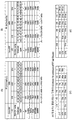
- FIG. 16 illustrates a table showing information related to a reception mode according to an embodiment of the present invention.
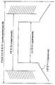
- FIG. 17 illustrates a bandwidth of a broadcast signal according to an embodiment of the present invention.
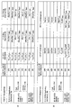
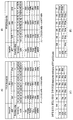
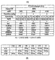
- 19 is a table showing transmission parameters for optimizing eBW according to an embodiment of the present invention.
- 20 is a table showing transmission parameters for optimizing eBW according to another embodiment of the present invention.
- 21 is a table showing transmission parameters for optimizing eBW according to another embodiment of the present invention.
- 22 is a table showing transmission parameters according to another embodiment of the present invention.
- FIG. 23 is a graph illustrating Power Spectral Density (PSD) of a transmission signal according to an embodiment of the present invention.
- PSD Power Spectral Density
- 24 is a table illustrating information related to a reception mode according to another embodiment of the present invention.
- 25 illustrates a relationship between a maximum channel estimation range and a guard interval according to an embodiment of the present invention.
- FIG. 26 is a diagram illustrating a table defining pilot parameters according to an embodiment of the present invention.
- 27 is a diagram illustrating a table defining pilot parameters according to another embodiment of the present invention.
- FIG. 30 illustrates a MIXO-2 pilot pattern according to an embodiment of the present invention.
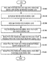
- 31 is a flowchart of a broadcast signal transmission method according to an embodiment of the present invention.
- 32 is a flowchart of a broadcast signal receiving method according to an embodiment of the present invention.
- the present invention is to provide an apparatus and method for transmitting and receiving broadcast signals for the next generation broadcast service.
- the next generation broadcast service according to an embodiment of the present invention is a concept including a terrestrial broadcast service, a mobile broadcast service, and a UHDTV service.
- the broadcast signal for the next generation broadcast service may be processed using a non-MIMO (Multi Input Multi Output) method or a MIMO method according to the characteristics of the broadcast service.
- the non-MIMO scheme according to an embodiment of the present invention may include a MISO (Multi Input Single Output), a SISO (Single Input Single Output) scheme, and the like.
- multiple antennas of MISO or MIMO may be described with two antennas as an example for convenience of description, but the description of the present invention may be applied to a system using two or more antennas.
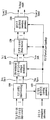
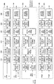
- FIG. 1 is a diagram illustrating a structure of a transmission apparatus for a next generation broadcast service according to an embodiment of the present invention.
- a transmission apparatus for a next generation broadcast service includes an input formatting module 1000, a coding & modulation module 1100, and a frame structure module 1200. It may include a waveform generation module 1300 and a signaling generation module 1400. Hereinafter, the operation of each module will be described.
- the apparatus for transmitting a next generation broadcast service may receive an MPEG-TS stream, an IP stream (v4 / v6), and a GS (generic stream) as input signals. .
- the input formatting module 1000 divides the input streams according to a criterion for performing coding and modulation or a service and service component criterion.
- a criterion for performing coding and modulation or a service and service component criterion.
- DPs or DP data may be referred to as DP data.
- the input formatting module 1000 divides each generated DP into block units necessary to perform coding and modulation, and performs a series of processes required to increase transmission efficiency or to schedule the DP. can do. Details will be described later.
- the coding and modulation module 1100 performs forward error correction (FEC) encoding on each DP received from the input formatting module 1000 to receive an error that may occur in a transport channel at a receiving end. Allow modification.
- the coding and modulation module 1100 according to an embodiment of the present invention may convert the bit data of the FEC output into symbol data and perform interleaving to correct a burst error due to a channel.
- the coding and modulation module 1100 according to an embodiment of the present invention provides a data path for outputting processed data to each antenna. (Or antenna path) can be output separately.
- the frame structure module 1200 may map data output from the coding and modulation module 1100 to a signal frame (or frame).
- the frame structure module 1200 may perform mapping by using the scheduling information output from the input formatting module 1000, and in the signal frame in order to obtain additional diversity gain. Interleaving can be performed on the data.
- the waveform generation module 1300 may convert the signal frames output from the frame structure module 1200 into a signal that can be finally transmitted.
- the waveform generation module 1300 according to an embodiment of the present invention inserts a preamble signal (or preamble) in order to obtain a signal frame of a transmission system in a receiver, estimates a transmission channel, and adjusts distortion.
- a reference signal can be inserted to compensate.
- the waveform generation module 1300 according to an embodiment of the present invention has a guard interval in order to cancel an influence caused by a channel delay spread due to multipath reception, and a specific sequence in a corresponding section. You can insert
- the waveform generation module 1300 according to an embodiment of the present invention may additionally perform a process necessary for efficient transmission in consideration of signal characteristics such as peak-to-average power ratio (PAPR) of an output signal. .
- PAPR peak-to-average power ratio
- the signaling generation module 1400 uses the input side information and information generated by the input formatting module 1000, the coding and modulation module 1100, and the frame structure module 1200.
- Signaling information (physical layer signaling information, hereinafter referred to as PLS information) is generated. Therefore, the reception apparatus according to an embodiment of the present invention can decode the received signal by decoding the signaling information.
- the transmitter for the next generation broadcast service may provide a terrestrial broadcast service, a mobile broadcast service, and a UHDTV service. Therefore, the apparatus for transmitting a next-generation broadcast service according to an embodiment of the present invention may multiplex signals for different services in a time domain and transmit the same.
- FIG. 2 to 4 illustrate an embodiment of the input formatting module 1000 according to an embodiment of the present invention described with reference to FIG. 1. Each figure is demonstrated below.
- FIG. 2 illustrates an input formatting module according to an embodiment of the present invention. 2 illustrates an input formatting module when the input signal is a single input stream.
- an input formatting module may include a mode adaptation module 2000 and a stream adaptation module 2100.
- the mode adaptation module 2000 includes an input interface block 2010, a CRC-8 encoder block 2020, and a BB header insertion block (20). 2030). Each block is briefly described below.
- the input interface block 2010 may output the input single input stream by dividing the input single input stream into units of a baseband (BB) frame length for performing FEC (BCH / LDPC).
- BB baseband
- the CRC-8 encoder block 2020 may add redundancy data by performing CRC encoding on data of each BB frame.
- the BB header insertion block 2030 may include a mode adaptation type (TS / GS / IP), a user packet length, a data field length, and a user packet sink byte ( User Packet Sync Byte, Start Address of User Packet Sync Byte in Data Field, High Efficiency Mode Indicator, Input Stream Synchronization Field, etc. Header can be inserted into the BB frame.
- a mode adaptation type TS / GS / IP
- a user packet length a data field length
- a user packet sink byte User Packet Sync Byte, Start Address of User Packet Sync Byte in Data Field, High Efficiency Mode Indicator, Input Stream Synchronization Field, etc. Header can be inserted into the BB frame.
- the stream adaptation module 2100 may include a padding insertion block 2110 and a BB scrambler block 2120. Each block is briefly described below.
- the padding insertion block 2110 may insert a padding bit and output the padding bit to have the required input data length.
- the BB scrambler block 2120 may randomize an input bit stream by performing an XOR using a pseudo random binary sequence (PRBS).
- PRBS pseudo random binary sequence
- the aforementioned blocks may be omitted or replaced by other blocks having similar or identical functions according to the designer's intention.
- the input formatting module may finally output the DP to the coding and modulation module.
- 3 illustrates an input formatting module according to another embodiment of the present invention. 3 illustrates a mode adaptation module of an input formatting module when the input signal is multiple input streams.
- the mode adaptation module of the input formatting module for processing multiple input streams may process each input stream independently.
- the mode adaptation module 3000 for processing multiple input streams respectively includes an input interface block, an input stream synchronizer block, and a compensating delay.
- a block, a null packet deletion block, a CRC-8 encoder block, and a BB header insertion block may be included. Each block is briefly described below.
- the input stream synchronizer block 3100 may transmit input stream clock reference (ISCR) information and insert timing information necessary for reconstructing a TS or GS stream at a receiving end.
- ISCR input stream clock reference
- the compensating delay block 3200 outputs the delayed input data so that the receiving device can synchronize in case of a delay between DPs according to data processing of the transmitting device together with timing information generated by the input stream synchronizer block. can do.
- the null packet deletion block 3300 may remove an input null packet to be transmitted unnecessarily and insert and transmit the number of removed null packets according to the removed position.
- the aforementioned blocks may be omitted or replaced by other blocks having similar or identical functions according to the designer's intention.
- FIG 4 illustrates an input formatting module according to another embodiment of the present invention.
- FIG. 4 illustrates a stream adaptation module of the input formatting module when the input signal is a multiple input stream.
- the stream adaptation module of the input formatting module in the case of multiple input streams may include a scheduler 4000, a 1-frame delay block 4100, in-band signaling or padding. It may include an in-band signaling or padding insertion block 4200, a physical layer signaling (PLS) block 4300, and a BB scrambler block 4400. The operation of each block will be described below.
- the scheduler 4000 may perform scheduling for a MIMO system using multiple antennas including dual polarity.
- the scheduler 4000 is a signal for each antenna path such as a bit to cell demux block, a cell interleaver block, and a time interleaver block in the coding and modulation module described with reference to FIG. 1. Parameters to be used in the processing blocks can be generated.
- the 1-frame delay block 4100 may delay the input data by one signal frame so that scheduling information for the next frame can be transmitted in the current frame for in-band signaling to be inserted into the DP.
- the in-band signaling or padding insertion block 4200 can insert non-delayed PLS-dynamic signaling information into data delayed by one signal frame.
- the in-band signaling or padding insertion block 4200 may insert padding bits when there is space for padding or insert in-band signaling information into the padding space.
- the scheduler 4000 may output PLS-dynamic signaling information for the current frame separately from in-band signaling. Accordingly, the cell mapper described later may map input cells according to scheduling information output from the scheduler 4000.
- the PLS generation block 4300 may generate PLS data (or PLS) to be transmitted to a preamble symbol or a spread symbol of a signal frame except for in-band signaling.
- PLS data according to an embodiment of the present invention may be referred to as signaling information.
- PLS data according to an embodiment of the present invention may be divided into PLS-free information and PLS-post information.
- the PLS-free information may include parameters necessary for the broadcast signal receiving apparatus to decode the PLS-post information and static PLS signaling information.
- the PLS-post information may include parameters necessary for the broadcast signal receiving apparatus to decode the DP. It may include.
- the parameters required for decoding the above-described DP may be separated into static PLS signaling information and dynamic PLS signaling information.
- the static PLS signaling information is a parameter that can be commonly applied to all frames included in the super frame and can be changed in units of super frames.
- the dynamic PLS signaling information is a parameter that can be applied differently for each frame included in the super frame and can be changed in units of frames. Therefore, the receiving device can decode the PLS-free information to obtain PLS-post information, and decode the desired DP by decoding the PLS-post information.
- the BB scrambler block 4400 may generate a PRBS so that the PAPR value of the output signal of the waveform generation block may be lowered and XOR the input bit string to output the PRBS. As shown in FIG. 4, scrambling of the BB scrambler block 4400 may be applied to both DP and PLS.
- the aforementioned blocks may be omitted or replaced by other blocks having similar or identical functions according to the designer's intention.
- the stream adaptation module may finally output each data pipe to a coding and modulation module.
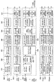
- FIG. 5 illustrates a coding and modulation module according to an embodiment of the present invention.
- the coding and modulation module of FIG. 5 corresponds to an embodiment of the coding and modulation module 1100 described with reference to FIG. 1.
- the transmitter for the next generation broadcast service may provide a terrestrial broadcast service, a mobile broadcast service, and a UHDTV service.
- the coding & modulation module can independently process and process SISO, MISO, and MIMO schemes for each of the input DPs.
- the transmission apparatus for the next generation broadcast service may adjust QoS for each service or service component transmitted through each DP.
- the coding and modulation module includes a first block 5000 for the SISO method, a second block 5100 for the MISO method, a third block 5200 for the MIMO method, and a PLS-free method. And a fourth block 5300 for processing the post information.
- the coding and modulation module illustrated in FIG. 5 is only an example, and according to a designer's intention, the coding and modulation module may include only the first block 5000 and the fourth block 5300, and the second block 5100. ) And only the fourth block 5300, or may include only the third block 5200 and the fourth block 5300. That is, according to the designer's intention, the coding and modulation module may include blocks for processing each DP identically or differently.
- the first block 5000 is a block for SISO processing the input DP.
- the FEC encoder block 5010, the bit interleaver block 5020, and a bit to cell demux are used.
- the block 5030 may include a constellation mapper block 5040, a cell interleaver block 5050, and a time interleaver block 5060.
- the FEC encoder block 5010 may add redundancy by performing BCH encoding and LDPC encoding on the input DP, and correct an error on a transport channel at the receiving end to output the FEC block.
- the bit interleaver block 5020 may interleave the bit string of the FEC-encoded data by interleaving rules so as to be robust against burst errors that may occur in the transport channel. Therefore, when K fading or deep erasure is applied to a QAM symbol, interleaved bits are mapped to each QAM symbol, thereby preventing errors in consecutive bits among all codeword bits. .
- the bit-to-cell demux block 5030 determines the order of the input bit strings so that each bit in the FEC block can be transmitted with appropriate robustness in consideration of both the order of the input bit strings and the constellation mapping rule. can do.
- bit interleaver 5020 is located between the FEC encoder 5010 and the constellation mapper block 5040, and considering the LDPC decode of the receiver, the output bits of the LDPC encoding performed by the FEC encoder block 5010 are converted to each other in the constellation mapper block. It may serve to connect with a bit position having another reliability and an optimal value. Accordingly, the bit to cell demux block 5030 may be replaced by another block having similar or identical functions.
- the constellation mapper block 5040 may map the input bit word to one constellation.
- the constellation mapper block may additionally perform rotation & Q-delay. That is, the constellation mapper block rotates the input constellations according to the rotation angle and divides the Q component into an arbitrary value after dividing it into I (In-phase) and Q (Quadrature-phase) components. Can be delayed. The paired I and Q components can then be remapped to a new constellation.
- the constellation mapper block 5040 may perform an operation of moving the constellation points on the two-dimensional plane to find the optimal constellation points. Through this process, the capacity of the coding and modulation module 1100 may be optimized. In addition, the constellation mapper block 5040 may perform the above-described operation using IQ-balanced constellation points and a rotation scheme. In addition, the constellation mapper block 5040 may be replaced by another block having similar or identical functions.
- the cell interleaver block 5050 randomly mixes and outputs cells corresponding to one FEC block, and outputs cells corresponding to each FEC block in different orders for each FEC block.
- the time interleaver block 5060 may mix and output cells belonging to several FEC blocks. Accordingly, since the cells of each FEC block are transmitted in a distributed manner as much as a time interleaving depth, diversity gain can be obtained.
- the second block 5100 is a block for MISO processing the input DP.
- the FEC encoder block, the bit interleaver block, the bit-to-cell demux block, and constellation are the same as the first block 5000. Although it may include a migration mapper block, a cell interleaver block, and a time interleaver block, there is a difference in that it further includes a MISO processing block 5110.
- the second block 5100 performs the same role process from the input to the time interleaver, and thus description of the same blocks will be omitted.
- the MISO processing block 5110 may perform encoding on an input series of cells according to an MISO encoding matrix that provides transmit diversity and output MISO processed data through two paths.
- MISO processing according to an embodiment of the present invention may include orthogonal space time block coding (OSTBC) / orthogonal space frequency block coding (OSA).
- OSTBC orthogonal space time block coding
- OSA orthogonal space frequency block coding
- the third block 5200 is a block for MIMO processing the input DP.
- the FEC encoder block, the bit interleaver block, the bit-to-cell demux block, and constellation are the same as the second block 5100. Although it may include a migration mapper block, a cell interleaver block, and a time interleaver block, there is a difference in data processing in that it includes a MIMO processing block 5220.
- the FEC encoder block and the bit interleaver block have different specific functions from those of the first and second blocks 5000 and 5100, but have the same basic role.
- the bit-to-cell demux block 5210 may generate an output bit string equal to the number of inputs of the MIMO processing and output the same through the MIMO path for the MIMO processing.
- the bit-to-cell demux block 5210 may be designed to optimize decoding performance of the receiver in consideration of characteristics of LDPC and MIMO processing.
- the constellation mapper block, the cell interleaver block, and the time interleaver block may also have different specific functions, but the basic role is the same as described in the first and second blocks 5000 and 5100.
- the constellation mapper block, the cell interleaver block, and the time interleaver blocks exist as many as the number of MIMO paths for MIMO processing to process the output bit string output from the bit-to-cell demux block. Can be.
- the constellation mapper block, the cell interleaver block, and the time interleaver block may operate identically or independently for data input through each path.
- the MIMO processing block 5220 may perform MIMO processing on the input two input cells using the MIMO encoding matrix and output the MIMO processed data through two paths.
- MIMO encoding matrix according to an embodiment of the present invention is the SM matrix (spatial multiplexing), golden code (Golden code), full-rate full diversity code (Full-rate full diversity code), linear dispersion code (Linear dispersion code) ) May be included.
- the fourth block 5300 is a block for processing the PLS-pre / post information, and may perform SISO or MISO processing.
- bit interleaver block, the bit to cell demux block, the constellation mapper block, the cell interleaver block, the time interleaver block, and the MISO processing block included in the fourth block 5300 are included in the second block 5100 described above. Blocks and specific functions may be different, but the basic role is the same.
- the shortened / punctured FEC encoder block 5310 included in the fourth block 5300 uses the FEC encoding scheme for the PLS path in case the length of the input data is shorter than the length required to perform FEC encoding. To process the PLS data. Specifically, the FEC encoder block 5310 performs BCH encoding on the input bit stream, then zero padding the length of the input bit stream necessary for normal LDPC encoding, and then pads zeros after the LDPC encoding. By removing, the parity bit can be punctured so that the effective code rate is equal to or lower than the DP.
- the blocks included in the first block 5000 to the fourth block 5300 described above may be omitted or replaced by other blocks having similar or identical functions according to a designer's intention.
- the coding and modulation module may output DP, PLS-pre information, and PLS-post information finally processed for each path to the frame structure module.
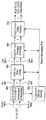
- FIG. 6 is a diagram illustrating a frame structure module according to an embodiment of the present invention.
- the frame structure module illustrated in FIG. 6 corresponds to an embodiment of the frame structure module 1200 described with reference to FIG. 1.
- the frame structure block includes at least one cell mapper 6000, at least one delay compensation module 6100, and at least one block interleaver ( 6200).
- the number of cell mapper 6000, delay compensation module 6100, and block interleaver 6200 can be changed according to a designer's intention. Hereinafter, the operation of each module will be described.
- the cell mapper 6000 may include cells corresponding to SISO or MISO or MIMO processed DPs output from the coding and modulation module, cells corresponding to common data that may be commonly applied between DPs, and PLS-pre / post information. Cells corresponding to may be allocated (or arranged) to a signal frame according to scheduling information.
- the common data refers to signaling information that can be commonly applied between all or some of the DPs and can be transmitted through a specific DP.
- a DP that transmits common data may be referred to as a common DP, which can be changed according to a designer's intention.
- the cell mapper 6000 may perform pair-wise cell mapping. That is, the cell mapper 6000 may process two consecutive cells with respect to the input cells in one unit and map them to a signal frame. Therefore, paired cells in the input path corresponding to the output path of each antenna may be allocated to positions adjacent to each other in the signal frame.
- the delay compensation block 6100 may delay the input PLS data cell for the next signal frame by one signal frame to obtain PLS data corresponding to the current signal frame.
- the PLS data of the current signal frame may be transmitted through a preamble region within the current signal frame
- the PLS data for the next signal frame may be transmitted through a preamble region within the current signal frame or through in-band signaling in each DP of the current signal frame. Can be sent. This can be changed according to the designer's intention.
- the block interleaver 6200 may obtain additional diversity gain by interleaving cells in a transport block that is a unit of a signal frame.
- the block interleaver 6200 may perform interleaving by processing two consecutive cells with respect to input cells as one unit. Therefore, the cells output from the block interleaver 6200 may be the same two consecutive cells.
- At least one cell mapper and at least one block interleaver may operate identically or independently for data input through respective paths.
- the aforementioned blocks may be omitted or replaced by other blocks having similar or identical functions according to the designer's intention.
- the frame structure module may output at least one signal frame to the waveform generation module.
- FIG. 7 illustrates a waveform generation module according to an embodiment of the present invention.
- the waveform generation module illustrated in FIG. 7 corresponds to an embodiment of the waveform generation module 1300 described with reference to FIG. 1.
- the waveform generation module may modulate and transmit signal frames as many as the number of antennas for receiving and outputting signal frames output from the frame structure module described with reference to FIG. 6.
- the waveform generation module illustrated in FIG. 7 is an embodiment of the waveform generation module of a transmission apparatus using m Tx antennas, and includes m processing blocks for modulating and outputting frames input by m paths. can do.
- the m processing blocks may all perform the same processing.
- the operation of the first processing block 7000 of the m processing blocks will be described.
- the first processing block 7000 includes a reference signal insertion & PAPR reduction block 7100, an inverse waveform transform block 7200, and a PAPR reduction in time.
- Block 7300 Guard Sequence Insertion Block 7400, Preamble Insertion Block 7500, Waveform Processing Block 7600, Other System Insulation insertion (block) 7770 and a digital analog conveter (DAC) block 7800.
- DAC digital analog conveter
- the reference signal insertion and PAPR reduction block 7100 may insert reference signals at predetermined positions for each signal block and apply a PAPR reduction scheme to lower the PAPR value in the time domain.
- the broadcast transmission / reception system according to an embodiment of the present invention is an OFDM system
- the reference signal insertion and PAPR reduction block 7100 may use a method of preserving without using some of the active subcarriers.
- the reference signal insertion and PAPR reduction block 7100 may not use the PAPR reduction scheme as an additional feature according to the broadcast transmission / reception system.
- the inverse waveform transform block 7200 may span the output signal and output the input signal in such a manner that transmission efficiency and flexibility are improved in consideration of the characteristics of the transmission channel and the system structure.
- the broadcast transmission / reception system according to an embodiment of the present invention is an OFDM system
- the inverse waveform transform block 7200 may use a method of converting a signal in a frequency domain into a time domain using an inverse FFT operation. Can be.
- the broadcast transmission / reception system according to an embodiment of the present invention is a single carrier system, the inverse waveform transform block may not be used in the waveform generation module.
- the PAPR reduction block 7300 may apply a method for lowering PAPR in the time domain with respect to the input signal.
- the PAPR reduction block 7300 may simply use a method of clipping peak amplitude.
- the PAPR reduction block 7300 is an additional feature and may not be used according to the broadcast transmission / reception system according to an embodiment of the present invention.
- the guard sequence insertion block 7400 may put a guard interval between adjacent signal blocks and insert a specific sequence if necessary in order to minimize the influence of the delay spread of the transport channel. Therefore, the receiving device can easily perform synchronization or channel estimation.
- the guard sequence insertion block 7400 may insert a cyclic prefix in the guard interval period of the OFDM symbol.
- the preamble insertion block 7500 may insert a known type signal (preamble or preamble symbol) between the transmitting and receiving devices into the transmission signal so that the receiving device can quickly and efficiently detect the system signal targeted by the receiving device. have.
- the preamble insertion block 7500 may define a signal frame composed of several OFDM symbols and insert a preamble at the beginning of every signal frame. have.
- the preamble may carry basic PSL data and may be located at the beginning of each signal frame.
- the waveform processing block 7600 may perform waveform processing on the input baseband signal to match the transmission characteristics of the channel.
- the waveform processing block 7600 may use a method of performing square-root-raised cosine filtering (SRRC) to obtain a criterion of out-of-band emission of a transmission signal in one embodiment. It may be.
- SRRC square-root-raised cosine filtering
- the waveform processing block 7600 may not be used.
- the other system insertion block 7700 may multiplex signals of a plurality of broadcast transmission / reception systems in a time domain to transmit data of a broadcast transmission / reception system providing two or more different broadcast services within the same RF signal bandwidth.
- two or more different systems refer to a system for transmitting different broadcast services.
- Different broadcast services may refer to terrestrial broadcast services or mobile broadcast services.
- data related to each broadcast service may be transmitted through different frames.
- the DAC block 7800 may convert an input digital signal into an analog signal and output the analog signal.
- the signal output from the DAC block 7800 may be transmitted through m output antennas.
- the transmit antenna according to an embodiment of the present invention may have a vertical or horizontal polarity.
- FIG. 8 is a diagram illustrating a structure of a reception device for a next generation broadcast service according to an embodiment of the present invention.
- the reception device for the next generation broadcast service may correspond to the transmission device for the next generation broadcast service described with reference to FIG. 1.
- a reception apparatus for a next generation broadcast service according to an embodiment of the present invention includes a synchronization & demodulation module 8000, a frame parsing module 8100, a demapping & decoding decoding module 8200, output processor 8300, and signaling decoding module 8400.
- a synchronization & demodulation module 8000 includes a frame parsing module 8100, a demapping & decoding decoding module 8200, output processor 8300, and signaling decoding module 8400.
- the synchronization and demodulation module 8000 receives an input signal through m reception antennas, performs detection and synchronization of a signal for a system corresponding to the reception device, and performs a transmission at the transmitter. Demodulation corresponding to the inverse process of the performed method may be performed.
- the frame parsing module 8100 may parse the input signal frame and extract data for transmitting a service selected by a user. If the frame parsing module 8100 performs interleaving in the transmitting apparatus, the frame parsing module 8100 may perform deinterleaving as a reverse process. In this case, the position of the signal and data to be extracted may be obtained by decoding the data output from the signaling decoding module 8400 by restoring scheduling information performed by the transmitting apparatus.
- the demapping & decoding module 8200 can perform the deinterleaving process if necessary after converting the input signal into data of the bit domain.
- the demapping & decoding module 8200 can demap the mapping applied for transmission efficiency, and perform error correction through decoding on an error generated during the transport channel.
- the demapping & decoding module 8200 can decode the data output from the signaling decoding module 8400 to obtain transmission parameters necessary for demapping and decoding.
- the output processor 8300 may perform a reverse process of various compression / signal processing processes applied by the transmitter to increase transmission efficiency.
- the output processor 8300 may obtain necessary control information from data output from the signaling decoding module 8400.
- the final output of the output processor 8300 corresponds to a signal input to the transmitting device, and may be MPEG-TS, IP stream (v4 or v6), and GS (generic stream).
- the signaling decoding module 8400 can obtain PLS information from the demodulated signal. As described above, the frame parsing module 8100, the demapping & decoding module 8200, and the output processor 8300 can perform functions of the corresponding module by using data output from the signaling decoding module 8400.
- FIG 9 illustrates a synchronization and demodulation module according to an embodiment of the present invention.
- the synchronization and demodulation module illustrated in FIG. 9 corresponds to an embodiment of the synchronization and demodulation module described with reference to FIG. 8.
- the synchronization and demodulation module illustrated in FIG. 9 may perform a reverse operation of the waveform generation module described with reference to FIG. 7.
- the synchronization and demodulation module is an embodiment of the synchronization and demodulation module of a receiving device using m Rx antennas, and inputs m paths. And m processing blocks for demodulating and outputting the received signal.
- the m processing blocks may all perform the same processing.
- the operation of the first processing block 9000 among the m processing blocks will be described.
- the first processing block 9000 is a tuner 9100, ADC block 9200, preamble detector 9300, guard sequence detector 9400, waveform transform ) Block 9500, time / freq sync block 9600, reference signal detector 9700, channel equalizer 9800, and inverse waveform transform waveform transform) block 9900.
- the tuner 9100 may select a desired frequency band and compensate the magnitude of the received signal to output the AD C block 9200.
- the ADC block 9200 may convert a signal output from the tuner 9100 into a digital signal.
- the preamble detector 9300 may detect a preamble (or a preamble signal or a preamble symbol) to determine whether the digital signal is a signal of a system corresponding to the receiving device. In this case, the preamble detector 9300 may decode basic transmission parameters received through the preamble.
- the guard sequence detector 9400 can detect the guard sequence in the digital signal.
- the time / frequency sync block 9600 can perform time / frequency synchronization using a detected guard sequence, and the channel equalizer 9800 can receive / restore using a detected guard sequence.
- the estimated sequence can be used to estimate the channel.
- the waveform transform block 9500 may perform an inverse transform process when an inverse waveform transform is performed at a transmitter.
- the waveform transform block 9500 may perform an FFT conversion process.
- the broadcast transmission / reception system according to an embodiment of the present invention is a single carrier system, when the received time domain signal is used to process in the frequency domain or is processed in all of the time domain, the waveform transform block 9500 ) May not be used.
- the time / frequency sync block 9600 receives output data of the preamble detector 9300, the guard sequence detector 9400, and the reference signal detector 9700, and provides guard sequence detection, block for the detected signal. Carrier frequency synchronization and time synchronization may be performed including block window positioning. In this case, the time / frequency sync block 9600 may feed back the output signal of the waveform transform block 9500 for frequency synchronization.
- the reference signal detector 9700 may detect the received reference signal. Therefore, the reception apparatus according to an embodiment of the present invention may perform synchronization or channel estimation.
- the channel equalizer 9800 may estimate a transmission channel from each transmission antenna to each reception antenna from a guard sequence or a reference signal, and perform channel compensation on each received data using the estimated channel.
- the inverse waveform transform block 9900 restores back to the original received data domain when the waveform transform block 9500 performs a waveform transform in order to efficiently perform synchronization and channel estimation / compensation. Can be performed.
- the waveform transform block 9500 may perform an FFT to perform synchronization / channel estimation / compensation in a frequency domain, and performs an inverse waveform.
- the transform block 9900 may restore the transmitted data symbols by performing IFFT on the signal on which channel compensation is completed. If the broadcast transmission / reception system according to an embodiment of the present invention is a multicarrier system, the inverse waveform transform block 9900 may not be used.
- FIG. 10 illustrates a frame parsing module according to an embodiment of the present invention.
- the frame parsing module illustrated in FIG. 10 corresponds to an embodiment of the frame parsing module described with reference to FIG. 8.
- the frame parsing module illustrated in FIG. 10 may perform a reverse operation of the frame structure module described with reference to FIG. 6.
- the frame parsing module may include at least one block interleaver 10000 and at least one cell demapper 10100.
- the block interleaver 10000 may perform deinterleaving on data in units of signal blocks with respect to data inputted through each data path of m reception antennas and processed by the synchronization and demodulation module. In this case, as described with reference to FIG. 8, when pairwise interleaving is performed at the transmitting side, the block interleaver 10000 may process two consecutive data for each input path as one pair. Accordingly, the block interleaver 10000 may output two consecutive output data even when deinterleaving is performed. In addition, the block interleaver 10000 may perform an inverse process of the interleaving process performed by the transmitter to output the original data in order.
- the cell demapper 10100 may extract cells corresponding to common data, cells corresponding to DP, and cells corresponding to PLS information from the received signal frame. If necessary, the cell demapper 10100 may output data in one stream by merging the data transmitted by being distributed into several parts. In addition, as described in FIG. 6, when the input data of two consecutive cells is processed and mapped as a pair at the transmitting end, the cell demapper 10100 performs two reverse input cells in one reverse process. Pairwise cell demapping that is processed in units may be performed.
- the cell demapper 10100 may extract and output PLS signaling information received through a current frame as PLS-free information and PLS-post information, respectively.
- the aforementioned blocks may be omitted or replaced by other blocks having similar or identical functions according to the designer's intention.
- FIG. 11 illustrates a demapping & decoding module according to an embodiment of the present invention.
- the demapping & decoding module illustrated in FIG. 11 corresponds to an embodiment of the demapping & decoding module described with reference to FIG. 8.
- the demapping & decoding module illustrated in FIG. 11 may perform a reverse operation of the coding and modulation module described with reference to FIG. 5.
- the coding and modulation module of the transmitting apparatus may independently process and process SISO, MISO, and MIMO schemes for respective paths to input data pipes. Accordingly, the demapping & decoding module illustrated in FIG. 11 may also include blocks for SISO, MISO, and MIMO processing of data output from the frame parser corresponding to the transmitting apparatus.
- the demapping & decoding module includes a first block 11000 for the SISO method, a second block 11100 for the MISO method, and a third for the MIMO method.
- a block 11200 and a fourth block 11300 for processing PLS pre / post information may be included.
- the demapping & decoding module illustrated in FIG. 11 is only an example, and according to the designer's intention, the demapping & decoding module may include only the first block 11000 and the fourth block 11300, and the second block. Only the first block 11100 and the fourth block 11300 may be included, or only the third block 11200 and the fourth block 11300 may be included. That is, according to the designer's intention, the demapping & decoding module can include blocks for processing each DP identically or differently.
- the first block 11000 is a block for SISO processing the input DP, a time de-ineterleaver block 11010, a cell de-interleaver block 11020, and a constellation demapper. (constellation demapper) block 11030, cell to bit mux block 11040, bit de-interleaver block 11050, and FEC decoder block 11060. can do.
- the time interleaver block 11010 may perform a reverse process of the time interleaver block 5060 described with reference to FIG. 5. That is, the time interleaver block 11010 may deinterleave the interleaved input symbols to their original positions in the time domain.
- the cell deinterleaver block 11020 may perform a reverse process of the cell deinterleaver block 5050 described with reference to FIG. 5. That is, the cell deinterleaver block 11020 may deinterleave the positions of the cells spread within one FEC block to the original positions.
- the constellation demapper block 11030 may perform a reverse process of the constellation demapper block 5040 described with reference to FIG. 5. That is, the constellation demapper block 11030 may demap the input signal of the symbol domain into the data of the bit domain. In addition, the constellation demapper block 11030 may perform a hard decision to output bit data according to the hard decision result, and to a soft decision value or a probabilistic value. Log-likelihood ratio (LLR) values of the corresponding bits can be output. If the rotated constellation is applied to obtain additional diversity gain at the transmitting end, the constellation demapper block 11030 may perform 2-D (Limensional) LLR demapping. In this case, when the LLR is calculated, the constellation demapper block 11030 may perform calculation to compensate for the delay value performed on the I or Q component by the transmitting apparatus.
- LLR Log-likelihood ratio
- the cell to bit mux block 11040 may perform a reverse process of the bit to cell demux block 5030 described with reference to FIG. 5. That is, the cell-to-bit mux block 11040 may restore the bit data mapped in the bit-to-cell demux block 5030 to the original bit stream form.
- the bit deinterleaver block 11050 may perform a reverse process of the bit interleaver block 5020 described with reference to FIG. 5. That is, the bit deinterleaver block 11050 may deinterleave the bit stream output from the cell-to-bit mux block 11040 in the original order.
- the FEC decoder block 11060 may perform an inverse process of the FEC encoder block 5010 described with reference to FIG. 5. That is, the FEC decoder block 11060 may correct an error generated on a transport channel by performing LDPC decoding and BCH decoding.
- the second block 11100 is a block for MISO processing the input DP, and as shown in FIG. 11, the time deinterleaver block, the cell deinterleaver block, and the constellation demapper block are the same as the first block 11000. , But may include a cell-to-bit mux block, a bit deinterleaver block, and an FEC decoder block, except that the MISO decoding block 1110 is further included. Like the first block 11000, the second block 11100 performs the same role from the time deinterleaver to the output, and thus description of the same blocks will be omitted.
- the MISO decoding block 11110 may perform a reverse process of the MISO processing block 5110 described with reference to FIG. 5.
- the MISO decoding block 11110 may perform Alamouti decoding.
- the third block 11200 is a block for MIMO processing the input DP, and as shown in FIG. 11, the time deinterleaver block, the cell deinterleaver block, and the constellation demapper block are the same as the second block 11100. It may include a cell-to-bit mux block, a bit deinterleaver block, and an FEC decoder block, but there is a difference in data processing in that it includes a MIMO decoding block 1112.
- the operations of the time deinterleaver, the cell deinterleaver, the constellation demapper, the cell-to-bit mux, and the bit deinterleaver blocks included in the third block 11200 are included in the first to second blocks 11000-11100. The operation and specific functions of the blocks may be different, but the basic role is the same.
- the MIMO decoding block 1112 may receive output data of the cell deinterleaver for m reception antenna input signals, and perform MIMO decoding as a reverse process of the MIMO processing block 5220 described with reference to FIG. 5.
- the MIMO decoding block 1210 may perform maximum likelihood decoding, or perform sphere decoding with reduced complexity in order to obtain the best decoding performance. Alternatively, the MIMO decoding block 1210 may perform MMSE detection or combine iterative decoding together to secure improved decoding performance.
- the fourth block 11300 is a block for processing PLS-pre / post information and may perform SISO or MISO decoding.
- the fourth block 11300 may perform a reverse process of the fourth block 5300 described with reference to FIG. 5.
- the operations of the time deinterleaver, the cell deinterleaver, the constellation demapper, the cell-to-bit mux, and the bit deinterleaver blocks included in the fourth block 11300 are included in the first to third blocks 11000-11200.
- the operation and specific functions of the blocks may be different, but the basic role is the same.
- the FEC decoder (11310) included in the fourth block (11300) may perform a reverse process of the shortened / punctured FEC encoder block 5310 described with reference to FIG. That is, the FEC decoder 11310 is shortened / punctured according to the length of the PLS data to perform de-shortening and de-puncturing on the received data, and then FEC decoding. Can be performed. In this case, since the FEC decoder used for the DP can be used for the PLS data in the same way, there is no need for a separate FEC decoding hardware for the PLS data, which has the advantage of easy system design and efficient coding.
- the aforementioned blocks may be omitted or replaced by other blocks having similar or identical functions according to the designer's intention.
- the demapping & decoding module can output DP and PLS information processed for each path to an output processor.
- FIG 12 illustrates an output processor according to an embodiment of the present invention.
- the output processor illustrated in FIG. 12 corresponds to an embodiment of the output processor described with reference to FIG. 8.
- the output processor illustrated in FIG. 12 receives a DP output from the demapping and decoding module and outputs a single output stream.
- the output processor may perform an inverse operation of the input formatting module described with reference to FIG. 2. .
- the output processor shown in FIG. 12 includes a BB scrambler block 12000, a padding removal block 12100, a CRC-8 decoder block 12200, and a BB frame processor ( BB frame processor) block 12300.
- the BB scrambler block 12000 may generate the same PRBS as used in the transmitter for the input bit stream, and perform descrambling by XORing the bit string.
- the padding remover block 12100 may remove the inserted padding bits as necessary at the transmitter.
- the CRC-8 decoder block 12200 may check a block error by performing CRC decoding on the bit stream received from the padding remover block 12100.
- the BB frame processor block 12300 may decode information transmitted in the BB frame header and restore MPEG-TS, IP stream (v4 or v6) or GS (Generic Stream) using the decoded information.
- the aforementioned blocks may be omitted or replaced by other blocks having similar or identical functions according to the designer's intention.
- FIG 13 illustrates an output processor according to another embodiment of the present invention.
- the output processor illustrated in FIG. 13 corresponds to an embodiment of the output processor described with reference to FIG. 8.
- the output processor illustrated in FIG. 13 corresponds to a case of receiving a plurality of DPs output from the demapping & decoding module.
- Decoding of a plurality of DPs is performed by merging and decoding common data and DPs associated therewith that can be commonly applied to a plurality of DPs, or when a receiving device uses a plurality of services or service components (SVCs). May include the case of decoding simultaneously).
- the output processor illustrated in FIG. 13 may include a BB descrambler block, a padding remover block, a CRC-8 decoder block, and a BB frame processor block as in the case of the output processor described with reference to FIG. 12.
- the operation and specific operation of the described blocks may be different, but the basic role is the same.
- the de-jitter buffer block 13000 included in the output processor illustrated in FIG. 13 stores delays arbitrarily inserted in a transmitter for sync between a plurality of DPs in a restored time to output (TTO) parameter. You can compensate accordingly.
- null packet insertion block 13100 may restore the null packet removed in the stream by referring to the recovered null packet (DNP) information and output common data.
- DNP recovered null packet
- the TS clock regeneration block 13200 may restore detailed time synchronization of an output packet based on input stream time reference (ISCR) information.
- ISCR input stream time reference
- the TS recombining block 13300 recombines the common data outputted from the null packet insertion block 13100 and the DPs associated with the original MPEG-TS, IP stream (v4 or v6) or GS (Generic). Stream to restore the output.
- TTO, DNP, and ISCR information may all be obtained through a BB frame header.
- the in-band signaling decoder block 13400 may restore and output in-band physical layer signaling information transmitted through a padding bit field in each FEC frame of the DP.
- the output processor shown in FIG. 13 performs BB descrambling of PLS-free information and PLS-post information input according to the PLS-free path and the PLS-post path, respectively, and decodes the descrambled data to perform original PLS decoding. You can restore the data.
- the recovered PLS data is transmitted to the system controller in the receiving device, and the system controller can supply the parameters required for the synchronization and demodulation module, the frame parsing module, the demapping & decoding module, and the output processor module of the receiving device.
- the aforementioned blocks may be omitted or replaced by other blocks having similar or identical functions according to the designer's intention.
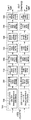
- FIG. 14 illustrates a coding and modulation module according to another embodiment of the present invention.
- the coding and modulation module illustrated in FIG. 14 corresponds to another embodiment of the coding and modulation module described with reference to FIGS. 1 and 5.
- the coding and modulation module illustrated in FIG. 14 includes a first block 14000 for the SISO scheme and a first scheme for the MISO scheme in order to adjust QoS for each service or service component transmitted through each DP.
- the coding and modulation module according to an embodiment of the present invention may include blocks for processing each DP identically or differently according to a designer's intention as described above.
- the first to fourth blocks 14000-14300 illustrated in FIG. 14 include blocks that are substantially the same as the first to fourth blocks 5000-5300 described with reference to FIG. 5.
- the functions of the constellation mapper block 14010 included in the first to third blocks 14000-14200 are included in the constellation mapper included in the first to third blocks 5000-5200 of FIG. 5. It differs from the function of the block 5040, and includes a rotation & I / Q interleaver block 1420 between the cell interleaver and the time interleaver of the first to fourth blocks 14000-14300. And the configuration of the third block 14200 for the MIMO scheme is different from that of the third block 5200 for the MIMO scheme shown in FIG. 5.
- a description of the same blocks as in FIG. 5 will be omitted and the description will be given based on the above-described differences.
- the constellation mapper block 14010 illustrated in FIG. 14 may map the input bit word into a complex symbol. However, unlike the constellation mapper block 5040 illustrated in FIG. 5, the constellation rotation may not be performed.
- the constellation mapper block 14010 illustrated in FIG. 14 may be commonly applied to the first to third blocks 14000-14200 as described above.
- the rotation and I / Q interleaver block 14020 independently interleaves the I (In-phase) component and the Q (Quadrature-phase) component of each complex symbol of the cell interleaved data output from the cell interleaver and outputs them in symbol units can do.
- the number of input data and output symbols of the rotation & I / Q interleaver block 14020 is two or more, which can be changed according to the designer's intention.
- the rotation & I / Q interleaver block 1420 may not interleave the I component.
- the rotation and I / Q interleaver block 1420 may be commonly applied to the first to fourth blocks 14000-14300 as described above. In this case, whether the rotation & I / Q interleaver block 1420 is applied to the fourth block 14300 for processing PLS-pre / post information may be signaled through the above-described preamble.
- the third block 14200 for the MIMO scheme may include a Q-block interleaver block 14210 and a complex symbol generator block 1422, as shown in FIG. have.
- the Q-block interleaver block 14210 may perform permutation on the parity part of the FEC block in which FEC encoding received from the FEC encoder is performed. In this way, the parity part of the LDPC H matrix can be made into a cyclic structure in the same way as the information part.
- the Q-block interleaver block 14210 can arrange the order of output bit blocks having the Q size of the LDPC H matrix. After permutation, row-column block interleaving may be performed to generate and output a final bit string.
- the complex symbol generator block 14220 may receive the bit strings output from the Q-block interleaver block 14210, and map the bit strings to complex symbols.
- the complex symbol generator block 1422 may output symbols through at least two paths. This can be changed according to the designer's intention.
- the aforementioned blocks may be omitted or replaced by other blocks having similar or identical functions according to the designer's intention.
- the coding and modulation module may output DP, PLS-free information, and PLS-post information processed for each path to the frame structure module.
- FIG. 15 illustrates a demapping & decoding module according to another embodiment of the present invention.
- the demapping & decoding module illustrated in FIG. 15 corresponds to another embodiment of the demapping & decoding module described with reference to FIGS. 8 and 11.
- the demapping & decoding module illustrated in FIG. 15 may perform a reverse operation of the coding and modulation module described with reference to FIG. 14.
- the demapping & decoding module includes a first block 15000 for the SISO method, a second block 15100 for the MISO method, and a third for the MIMO method.
- a block 15200 and a fourth block 15300 for processing PLS pre / post information may be included.
- the demapping & decoding module according to an embodiment of the present invention may include blocks for processing each DP identically or differently according to a designer's intention as described above.
- the first to fourth blocks 15000-15300 illustrated in FIG. 15 include blocks that are substantially the same as the first to fourth blocks 11000-11300 described with reference to FIG. 11.
- an I / Q deinterleaver & derotation block 15010 is included between the time deinterleaver and the cell deinterleaver of the first to fourth blocks 15000-15300.
- the constellation demapper block included in the first to third blocks 11000-11200 of FIG. 11 includes the functions of the constellation demapper block 15020 included in the first through third blocks 15000-15200.
- the structure of the third block 15200 for the MIMO scheme and the configuration of the third block 11200 for the MIMO scheme is different from the function of (11030).
- the description of the same blocks as in FIG. 11 will be omitted and the description will be given based on the above-described differences.
- the I / Q deinterleaver and derotation block 15010 may perform a reverse process of the rotation and I / Q interleaver block 1140 described with reference to FIG. 14. That is, the I / Q deinterleaver and derotation block 15010 may deinterleave the I and Q components transmitted by I / Q interleaving at the transmitter, respectively, and have a complex symbol having reconstructed I / Q components. You can derotate the output again.
- the I / Q deinterleaver and derotation block 15010 may be commonly applied to the first to fourth blocks 15000-15300 as described above. In this case, whether the I / Q deinterleaver and derotation block 15010 is applied to the fourth block 15300 for processing the PLS-pre / post information may be signaled through the above-described preamble.
- the constellation demapper block 15020 may perform a reverse process of the constellation mapper block 14010 described with reference to FIG. 14. That is, the constellation demapper block 15020 may perform demapping on cell deinterleaved data without performing derotation.
- the third block 15200 for the MIMO scheme may include a complex symbol parsing block 15210 and a Q-block deinterleaver block 15220, as shown in FIG. 15. Can be.
- the complex symbol parsing block 15210 may perform an inverse process of the complex symbol generator block 1422 described with reference to FIG. 14. In other words, the complex data symbol may be parsed, demapping into bit data, and output. In this case, the complex symbol parsing block 15210 may receive complex data symbols through at least two paths.
- the Q-block deinterleaver block 15220 may perform a reverse process of the Q-block interleaver block 14210 described with reference to FIG. 14. That is, the Q-block deinterleaver block 15220 restores the Q size blocks by row-column deinterleaving, and then restores the order of each permutated block in the original order. By parity deinterleaving, the parity bits may be restored to their original positions and output.
- the aforementioned blocks may be omitted or replaced by other blocks having similar or identical functions according to the designer's intention.
- the demapping & decoding module can output DP and PLS information processed for each path to the output processor.
- the broadcast signal transmission apparatus or the above-described waveform transform block 7200 inserts pilots to a signal frame output from the frame structure module 1200 and uses transmission parameters.
- Broadcast signals may be OFDM modulated.
- Transmission parameters according to an embodiment of the present invention may be referred to as OFDM parameters.
- the present invention proposes transmission parameters that can maximize transmission efficiency and apply to various reception scenarios while satisfying the in-band spectrum mask criterion for the next generation broadcast transmission / reception system.
- FIG. 16 illustrates a table showing information related to a reception mode according to an embodiment of the present invention.
- the table of FIG. 16 includes a network configuration according to a reception mode of a next generation broadcast transmission / reception system.
- the reception mode according to an embodiment of the present invention may be classified into a fixed rooftop, a handheld portable environment, and a handheld mobile environment.
- a representative channel can be determined.
- the broadcast signal transmission apparatus may determine the transmission mode according to the reception mode described above. That is, the broadcast signal transmission apparatus according to an embodiment of the present invention may process and transmit broadcast service data in a non-MIMO method (MISO and SISO method) or a MIMO method according to the characteristics of the broadcast service, that is, the reception mode. Accordingly, the broadcast signal according to each transmission mode may be transmitted and received through a transmission channel corresponding to the corresponding processing scheme.
- MISO and SISO method non-MIMO method
- MIMO method MIMO method according to the characteristics of the broadcast service
- each transmission mode may be distinguished and transmitted in units of signal frames according to an embodiment.
- each signal frame may include a plurality of OFDM symbols, and each OFDM symbol may include a plurality of data symbols for transmitting data corresponding to the above-described preamble (or preamble symbols) and a broadcast signal.
- the left column of the table of FIG. 16 shows the three reception modes described above.
- the broadcast signal reception apparatus may receive a broadcast signal through a rooftop antenna corresponding to a height of 10m or more above the ground. Therefore, since the direct path is secured, the Rician channel is typically used, the influence of the Doppler is small, and the delay spread of the channel according to the use of the directional antenna is used. The range of may be limited.
- the broadcast signal receiving apparatus may receive a broadcast signal through an omni-directional antenna corresponding to a height of 1.5 m or less above the ground.
- a Rayleigh channel is typically used as a transmission channel environment by reflected waves, and a range of delay spread of a channel longer than that of the directional antenna can be secured.
- the handheld portable environment can support a low level Doppler environment in consideration of mobility of walking level as an indoor / outdoor reception environment.
- the handheld portable environment may be classified into a fixed environment and a pedestrian environment.
- Handheld mobile environments can support high Doppler environments by considering not only the walking level of the receiver, but also the speed at which the vehicle travels, such as cars and trains.
- the right side of the table of Fig. 16 shows the network configuration according to each reception mode.
- the network configuration refers to a network structure, and the network configuration according to an embodiment of the present invention is a single frequency network (MFN) consisting of a plurality of frequencies and a single frequency (SFN) consisting of one frequency according to frequency operation in a network. ) Can be distinguished.
- MFN single frequency network
- SFN single frequency
- MFN is a network structure for transmitting broadcast signals using many frequencies in a large area.
- a plurality of transmission towers or broadcast signal transmitters located in the same area may transmit broadcast signals through different frequencies. .
- a delay spread due to natural echo generated by the terrain, features, etc. in the network may be formed.
- the broadcast signal receiver since the broadcast signal receiver receives only one radio wave, the reception quality may be determined according to the magnitude of the received radio wave.
- SFN refers to a network structure in which a plurality of broadcast signal transmitters located in the same region transmit the same broadcast signal through the same frequency.
- a maximum delay spread of a transmission channel may occur due to an additional man-made echo.
- the reception quality may be affected by the mutual ratio between the radio wave to be received and the radio wave of the disturbing frequency, the delay time, and the like.
- the value of the guard interval is determined in consideration of the maximum delay spread of the transmission channel in order to minimize the inter symbol interference. Since the guard interval is redundant data additionally inserted into the transmitted broadcast signal, the overall symbol duration should be designed to minimize the SNR loss in consideration of the overall transmission power efficiency.
- FIG. 17 illustrates a bandwidth of a broadcast signal according to an embodiment of the present invention.
- the bandwidth of a broadcast signal is the same as the waveform transform bandwidth, and the waveform transform bandwidth corresponds to a channel bandwidth and a spectrum mask.
- the channel bandwidth may include a signal bandwidth.
- the transmission parameter according to an embodiment of the present invention maximizes transmission efficiency within the bandwidth of the corresponding broadcast signal while satisfying a spectrum mask required to minimize interference of adjacent channels within the corresponding channel bandwidth allocated in the next generation broadcast transmission / reception system. It must be designed to In addition, since the above-described waveform generation module 1300 may use a plurality of carriers to transform the input signal, the transmission parameter according to an embodiment of the present invention may be used for transformation in a waveform transform bandwidth. The interval of each subcarrier may be adjusted according to the number of subcarriers used, the total symbol length may be determined in the time domain, and the transmission mode suitable for the reception scenario of the next generation broadcast transmission / reception system may be classified and designed based on this.
- FIG. 18A is a table showing values of guard intervals as transmission parameters according to the reception mode and network configuration described above
- FIG. 18B is a table illustrating vehicle speeds as transmission parameters according to the reception mode and network configuration described above. Table shows the values of vehicle speed).
- the guard interval may be designed in consideration of the maximum delay spread based on the network configuration and the environment of the reception antenna according to the reception scenario.
- the vehicle speed as a transmission parameter may be designed and determined by reflecting the environment of the network configuration and the reception antenna according to the classification of the reception scenario.
- a method of setting a guard interval (or elementary guard interval) and vehicle speed and optimizing transmission parameters using an optimization scaling factor or an optimization scaling factor for design optimization of a next generation broadcast transmission / reception system Suggest.
- a symbol (or OFDM symbol) included in a signal frame according to an embodiment of the present invention may be transmitted during a specific duration.
- Each symbol may also include a usable part corresponding to an active symbol duration length and a guard interval area corresponding to a guard interval.
- the guard interval region may be located in front of the use pool region.
- the guard intervals according to the embodiment of the present invention correspond to NG_a1, NG_a2,... , NG_b1, NG_b2,... , NG_c1, NG_c2,... , NG_d1, NG_d2,... , NG_e1, NG_e2,... , NG_f1, NG_f2,... , NG_g1, NG_g2,... , NG_h1, NG_h2,... It can be set to.
- Guard intervals (a) and (b) shown in (A) mean an embodiment of the guard interval that can be applied to the next generation broadcast transmission and reception system according to an embodiment of the present invention.
- the guard interval (a) is 25us
- the guard interval (b) is an embodiment in the case of setting the 30us as the elementary guard interval
- the optimization according to the network structure and the optimization for the transmission efficiency and SNR loss of the transmission signal The example in which the scaling factor is set to Lalpha1, Lalpha2, Lbeta1, and Lbeta2 is shown.
- the vehicle speed according to the embodiment of the present invention is quasi static, ⁇ Vp_a1 km / h, ⁇ Vp_b1 km / h, Vm_a1 km / h to Vm_a2 km / h, for each of the above-described reception modes. It may be set to Vm_b1 km / h ⁇ Vm_b2 km / h.
- the vehicle speed (a) shown in (B) is an embodiment of the vehicle speed that can be applied to the next-generation broadcast transmission and reception system according to an embodiment of the present invention quasi-static, 3km / h, 3km according to each reception scenario Optimizing scaling factor, Valpha1, Valpha2, Vbeta1, for setting the / h ⁇ 200km / h as the elementary vehicle speed and optimizing the network structure and optimizing the transmission efficiency and time-varying channel estimation of the transmission signal. Shows an example in which Vbeta1 is set.
- eBW effective signal bandwidth
- Nwaveform_scaling shown in Equation 1 means a waveform scaling factor
- Npilotdensity means a pilot density scaling factor
- NeBW means an effective signal bandwidth scaling factor
- ⁇ denotes an additional bandwidth.
- Fs also means sampling frequency.
- the above-described factors are used as optimization parameters (or optimization parameters) to determine the eBW optimized for the spectral mask according to the channel bandwidth.
- optimization parameters or optimization parameters
- the waveform scaling factor is a scaling value according to a bandwidth of a carrier used for waveform transformation.
- the waveform scaling factor according to an embodiment of the present invention is an arbitrary proportional to the length of a nonquispaced fast Fourier transform (NFFT) for OFDM. It can be set to a value.
- NFFT nonquispaced fast Fourier transform
- the pilot density scaling factor may be set according to the density of the reference signal as a value set according to a predetermined position of the reference signal inserted in the reference signal insertion and PAPR reduction block 7100.
- the effective signal bandwidth scaling factor is set to any value that can maximize the bandwidth of the transmission signal while satisfying the specification of the spectral mask within the transmission channel bandwidth. This allows you to design optimized eBWs.
- the additional bandwidth factor may be set to an arbitrary value to adjust additional information and structure required in the transmission signal bandwidth.
- the additional bandwidth factor may also insert a reference signal to insert an edge of the spectrum. (edge) can be used to improve channel estimation performance.
- NoC Number of Carrier is the total number of carriers transmitted through the signal bandwidth, it can be represented by the formula contained in the braces of the equation.
- the broadcast signal transmission apparatus may use the waveform transform bandwidth as a transmission parameter for additionally optimizing eBW according to the number of subcarriers used for modification.
- the broadcast signal transmission apparatus may use the above-described effective signal bandwidth scaling factor as a transmission parameter for optimizing eBW.
- the effective signal bandwidth scaling factor may be set to a maximum value optimized for the spectral mask by extending the pilot density unit of the preset reference signal.
- the apparatus for transmitting broadcast signals according to an embodiment of the present invention adjusts the waveform transform bandwidth, that is, the sampling frequency, of the ambiguities that can be generated according to the pilot density unit, thereby applying the effective signal bandwidth scaling factor to the spectrum mask. You can decide.
- 19 is a table showing transmission parameters for optimizing eBW according to an embodiment of the present invention.
- the transmission parameters illustrated in FIG. 19 are transmission parameters for optimizing eBW of a next generation broadcasting system applying the OFDM scheme while complying with a Federal Communications Commission (FCC) spectrum mask for a 6 MHz channel bandwidth.
- FCC Federal Communications Commission
- (A) is a table showing transmission parameters (example (A)) set for the guard interval (a) and the vehicle speed (a) according to the embodiment of the present invention described above, and (B) Table showing transmission parameters (example (B)) set for the guard interval (b) and vehicle speed (b) according to an embodiment of the invention.
- (A ') is a table showing an embodiment of the GI duration for combining the FFT and the GI mode set in accordance with the above-mentioned (A)
- (B') is the FFT (NFFT) set in accordance with the above-mentioned (B) and Table showing an embodiment of a GI duration for combining GI modes.
- the transmission parameters shown in (A) and (B) have been set for three FFT modes of 8K, 16K and 32K, but are applicable even when the FFT mode is 1K / 2K / 4K / 64K. Also, (A) and (B) illustrate embodiments of optimization scaling factors that can be applied according to each FFT mode.
- the broadcast signal transmission apparatus may insert a reference signal into a time and frequency domain in consideration of the transmission parameters described in (A) and (B), a reception scenario, and a network configuration. It can be used as additional information for synchronization and channel estimation.
- the broadcast signal transmission apparatus may set the density (Npilotdensity) of the reference signal and the optimized eBW in consideration of the ratio of the channel estimation range to the guard interval.
- the waveform scaling factor according to an embodiment of the present invention may be determined in proportion to the FFT size according to each FFT mode.
- the waveform transform bandwidth that is, the sampling frequency is adjusted. It is possible to determine the maximum signal bandwidth that does not exceed the spectral mask.
- the sampling frequency may be used to determine the optimized signal bandwidth and to determine the OFDM symbol duration and subcarrier spacing. Accordingly, the sampling frequency may be determined in consideration of not only the transmission channel and reception scenario of the guard interval and vehicle speed described above, but also the efficiency and SNR loss of the transmission signal.
- (A) of the figure shows an embodiment in which the value of Fs is 221/32 MHz
- (B) shows an embodiment in which the value of Fs is (1753/256) MHz.
- Fc shown in (A) and (B) means the central frequency (central frequency) of the RF signal
- Tu means the active symbol duration.
- 20 is a table showing transmission parameters for optimizing eBW according to another embodiment of the present invention.
- (A) is a table showing the same transmission parameters (example (A)) in FIG. 19A.
- (B) is a table showing transmission parameters (example (B-1)) set for the guard interval (b) and the vehicle speed (b) as another embodiment of the table of FIG. 19B.
- (A ') is a table showing an embodiment of the GI duration for combining the FFT and GI mode set according to (A), and (B') shows the combination of the FFT and GI mode set according to (B) described above. Table showing an embodiment of a GI duration.
- each transmission parameter shown in FIG. 20 are the same as in FIG. 19 except that the Tu value in the center column of FIG. 20B is changed to 2392.6 unlike FIG. Omit.
- 21 is a table showing transmission parameters for optimizing eBW according to another embodiment of the present invention.
- (A) is a table which shows the other Example of (B) demonstrated in FIG. Specifically, (A) is a table showing transmission parameters (example (B-2)) when the value of Fs is 219/32 MHz.
- (B) is a table showing an embodiment of the GI duration for combining the FFT and the GI mode set according to the above-mentioned (A).
- the transmission parameters shown in (A) are different in that the fc and Tu values are increased, but the eBW values are decreased, compared with the transmission parameters shown in FIG.
- the eBW value may be a value that can be set as a factor with respect to the channel bandwidth.
- 22 is a table showing transmission parameters according to another embodiment of the present invention.
- FIG. 22A shows a derivation of a scaling factor and an Fs value corresponding to channel bandwidths of 5, 7, and 8 MHz of the above-described embodiments by a product of a scaling factor calculated based on an Fs value of 6 MHz. Results are shown.
- the scaling factor corresponds to the ratio of the channel bandwidth.
- FIG. 22B illustrates a table showing transmission parameters for optimizing the eBW described with reference to FIGS. 19 to 21.
- the table located at the top of (B) shows transmission parameters corresponding to channel bandwidths of 5, 6, 7, and 8 MHz of the example (A) described with reference to FIGS. 19 and 20.
- the table located in the middle of (B) shows transmission parameters corresponding to channel bandwidths of 5, 6, 7, and 8 MHz in the example (B-1) described with reference to FIG. 20.
- the table located at the bottom of (B) shows transmission parameters corresponding to channel bandwidths of 5, 6, 7, and 8 MHz in the example (B-2) described with reference to FIG. 21.
- the second row of (A) shows the result obtained by ringing the setting of the Fs value corresponding to each channel bandwidth in the table located at the top of (B) by the product of the scaling factor calculated based on the Fs value of 6MHz.
- the third row of (A) shows the result obtained by ringing the setting of the Fs value corresponding to each channel bandwidth in the table located in the center of (B) by the product of the scaling factor calculated based on the Fs value of 6 MHz.
- the third row of (A) shows the result of annularly deriving the setting of the Fs value corresponding to each channel bandwidth from the table located at the bottom of (B) by the product of the scaling factor calculated based on the Fs value of 6MHz.
- FIG. 23 is a graph illustrating Power Spectral Density (PSD) of a transmission signal according to an embodiment of the present invention.
- PSD Power Spectral Density
- the left graph of (A) shows the PSD of the transmission signal optimized for the FCC spectral mask of the example (A) described in FIGS. 19 to 20, and the right graph of (A) shows the result of enlarging a part of the left graph. .
- the left graph of (B) shows the PSD of the transmission signal optimized for the FCC spectral mask of the example (B) described in FIG. 19, and the right graph of (B) shows an enlarged part of the left graph.
- each graph plots the PSD of the transmitted signal derived using a line indicating the specification of the FCC spectral mask and transmission parameters corresponding to 8K, 16K and 32K, respectively. Indicates lines that represent.
- the PSD of each transmission signal at a breakpoint of the target spectral mask should not exceed the threshold of the spectral mask.
- the PSD of the out of band emission transmission signal may be band-limited by the baseband filter.
- 24 is a table illustrating information related to a reception mode according to another embodiment of the present invention.
- FIG. 24 corresponds to another embodiment of a table illustrating information related to the reception mode described in FIG. 16, and illustrates a table showing network configuration, FFT value (NFFT), guard interval, and vehicle speed corresponding to each reception mode. Guard interval and vehicle speed values are the same as described with reference to FIG. 18.
- a large FFT such as 16K and 32K can be used.
- transmission can be performed to increase the efficiency of data with respect to redundancy ratios such as guard intervals and reference signals suitable for network configuration.
- an FFT such as 8K, 16K, and 32K, which supports a low level Doppler environment and can support high frequency sensitivity, can be used.
- guard interval according to an embodiment of the present invention may be set to support the same level of coverage in consideration of the network configuration of each reception.
- the broadcast signal transmission apparatus or the above-described waveform transform block 7200 inserts pilots to a signal frame output from the frame structure module 1200 and uses transmission parameters.
- Broadcast signals may be OFDM modulated.
- Various cells in an OFDM symbol may be modulated using reference information, ie pilots.
- the pilot may be used to transmit information already known by the broadcast signal receiver, and each pilot may be transmitted at a power level specified according to the pilot pattern.
- Pilots according to an embodiment of the present invention may be used for frame synchronization, frequency and time synchronization, channel estimation, and the like.
- the pilot mode according to an embodiment of the present invention is information for indicating a pilot set for transmitting an optimized broadcast signal and reducing overhead of transmission parameters according to the above-described reception environment.
- the pilot pattern according to an embodiment of the present invention may be variously set according to the reception mode and the FFT size described above.
- the pilot pattern and pilot mode described below may be equally applied to the above-described reception mode and network configuration.
- a pilot pattern and a pilot mode according to an embodiment of the present invention may be applied to data symbols in a signal frame.
- 25 illustrates a relationship between a maximum channel estimation range and a guard interval according to an embodiment of the present invention.
- Equation 1 is for determining an effective signal bandwidth of a transmission signal, and a pilot density scalable factor may be used as an optimization parameter.
- Equation 1 may be determined by optimizing values of pilot density, Dx, and Dy related to time, frequency placement, and data efficiency of the pilot signal for SISO channel estimation.
- the pilot density corresponds to the product of the distance between pilots in the time and frequency domain, and the pilot overhead occupied by the pilot in the symbol corresponds to the inverse of the pilot density.
- Dx means the distance between pilots in the frequency domain
- Dy means the distance between pilots in the time domain.
- Dy can be used to determine the maximum tolerable doppler speed. Therefore, Dy may be determined as an optimized value reflecting the vehicle speed determined according to the classification of the reception scenario.
- the values of Dx and Dy may be set in consideration of the transmission efficiency along with the state of the transmission channel.
- the transmission channel is set differently according to the reception mode described above. Can be.
- the maximum channel estimation range TChEst illustrated in FIG. 25 may be determined by a value obtained by dividing the above-described transmission parameter Tu by Dx.
- the maximum channel estimation range may include a guard interval having a predetermined length, a pre-echo region and a post-echo region.
- the ratio of the given guard interval to the maximum channel estimation range means the margin of the channel estimation range from which the guard interval can be estimated. If the margin value of the channel estimation range exceeds the length of the guard interval, the excess values may be assigned to the pre echo region and the post echo region, respectively.
- the pre-echo and post-echo areas can be used to estimate the channel impulse response beyond the length of the guard interval, and can be used as an area used for estimating or compensating for timing errors that may occur during synchronization. have. However, larger margins can increase pilot overhead and reduce transmission efficiency.
- 26 and 27 show tables defining pilot parameters according to the above-described guard intervals (A) and (B) and vehicle speed. Each drawing is demonstrated below.
- FIG. 26 is a diagram illustrating a table defining pilot parameters according to an embodiment of the present invention.
- FIG. 26 is a diagram illustrating pilot parameters according to the above-described guard interval (A) and vehicle speed, (A) is a table showing pilot patterns used for SISO and MIXO transmission channels, and (B) is a table for SISO and MIXO transmission channels. The configuration of the pilot pattern used for, (C) is a table showing the configuration of the pilot pattern used for the MIXO transmission channel.
- (A) shows pilot patterns determined for each pilot density value and Dx and Dy values defined for each of the SISO and MIXO transport channels for each pilot pattern.
- the pilot pattern according to an embodiment of the present invention may be represented as PP5-4, where the first number means the value of Dx and the second number means the Dy value.
- PP5-4 the first number means the value of Dx
- the second number means the Dy value.
- a smaller value of Dx can support longer delay spreads, and a smaller value of Dy can adapt to a faster Doppler environment.
- (B) and (C) are tables showing the pilot pattern configuration according to the guard interval duration and the FFT value. Specifically, the numbers shown in the first row of the tables shown in (B) and (C) indicate the duration of the guard interval, and the first column indicates the FFT value (NFFT) described with reference to FIGS. 19 to 22.
- (B) and (C) are the same in that they represent the configuration of the pilot pattern in the case of MIXO, but (B) represents the pilot pattern of the version (MIXO-1) with a larger pilot overhead, and (C) The difference is that it represents the pilot pattern of the less mobile version (MIXO-2).
- the duration of the guard interval shown in (B) and (C) described above is the same concept as the length of the guard interval described in FIG. 25, and has values of 25us, 50us, 100us, 200us, and 400us in consideration of the maximum delay spread.
- the FFT size may be 8K, 16K, and 32K.
- Dx may have a value of 5, 10, 20, 40, 80, 160 in consideration of the duration of the guard interval and the FFT size.
- the elementary Dx value 5, which is a basic value may be defined as a value that may vary according to each transmission mode, and is set in consideration of the margin of the channel estimation range described above by about 20%. You can do
- the margin value of the channel estimation range of the present invention may be adjusted by using values of Lalpha1 in MFN and Lalpha2 in SFN.
- a value of Dy may be set according to a reception scenario and a transmission mode according to a reception scenario. Therefore, the Dy value may be set to different values depending on whether the SISO or MIXO transmission channel is used. As shown in the figure, Dy may be set to a value of 2, 4, and 8 in the case of an SISO transport channel.
- the Dy value may be set differently according to each version.
- the larger pilot overhead (MIXO-1) is intended to increase pilot overhead to support the same maximum delay spread and maximum mobile speed in the same network configuration as the SISO transport channel, in which case the value of Dy is equal to the SISO transport channel. Similarly, it may be set to a value of 2, 4 and 8. That is, the MIXO-1 transport channel may be applied in the handheld portable environment or the handheld mobile environment.
- MIXO-2 The less mobile version (MIXO-2) is intended to guarantee the same coverage and capacity as the SISO transport channel, even though it is somewhat of a loss in mobile speed support, in which case the value of Dy is 4 It can be set to a value of 8,16.
- 27 is a diagram illustrating a table defining pilot parameters according to another embodiment of the present invention.
- FIG. 27 is a diagram illustrating pilot parameters according to the above-described guard interval (B) and vehicle speed
- (A) is a table showing pilot patterns used for SISO and MIXO transmission channels
- (B) is a table for SISO and MIXO transmission channels.
- (C) is a table showing the configuration of the pilot pattern used for the MIXO transmission channel.
- the structure and position of the pilot for MIXO (MISO, MIMO) transmission channel estimation can be set through the above-described pilot pattern.
- a null encoding and a hardware encoding scheme may be used as pilot encoding schemes for separating transport channels.
- the following equation is an equation representing a nulling encoding scheme.
- the nulling encoding method Since the nulling encoding method has no mutual channel interference in estimating each channel, errors in channel estimation can be minimized and it is easy to estimate an independent channel when using symbol timing synchronization. However, since the gain of the pilot must be amplified to obtain the channel estimation gain, the influence of Inter Channel Interference (ICI) of adjacent data by the pilot according to the time-varying channel is relatively large, and the position of the pilot allocated to each channel according to the pilot arrangement If not the same may have the disadvantage that the SNR of the effective data can be changed for each symbol.
- the MIXO-1 pilot pattern according to the embodiment of the present invention described above may be advantageously used even in the case of a nulling encoding scheme. Details will be described later.
- the following equation is an equation representing a nulling encoding scheme.
- channel estimation can be performed through simple linear calculation, and the gain of noise average effect can be obtained compared to the nulling encoding method.
- errors in cross-channel estimation may affect other channels, and ambiguity may occur in symbol timing synchronization using a pilot.
- the apparatus for transmitting broadcast signals according to an embodiment of the present invention may set the above two encoding schemes as MIXO pilot encoding schemes according to a reception scenario and a state of a transmission channel according to a preset mode.
- the broadcast signal receiving apparatus according to an embodiment of the present invention may perform channel estimation through a preset mode.
- the pilot pattern shown in FIG. 28 represents the pattern of the SISO pilot when the pilot density described in FIG. 27 is 32.
- the pilot may be inserted in the data symbol region of the signal frame.
- the horizontal axis of the pilot pattern shown in the figure represents the frequency axis, and the vertical axis represents the time axis.
- pilots consecutively arranged at both ends of the pilot pattern are reference signals inserted to compensate for distortion at the spectral edges generated during channel estimation.
- (A) shows the case where the pilot pattern is PP4-8
- (B) shows the case where the pilot pattern is PP8-4
- (C) shows the case where the pilot pattern is PP16-2. That is, as shown in (A), the pilot may be input periodically in units of four carriers on the frequency axis, and each pilot may be input in units of eight symbols on the time axis.
- (B) and (C) also show patterns of pilots input in the same manner.
- the pilot pattern for the other pilot density described with reference to FIG. 27 may be represented by adjusting the values of Dx and Dy in this figure.
- the pilot pattern shown in FIG. 29 represents the pattern of the MIXO-1 pilot when the pilot density described in FIG. 27 is 32, and indicates the pilot pattern when there are two transmit antennas.
- pilots consecutively arranged at both ends of the pilot pattern are reference signals inserted to compensate for distortion at the spectral edges generated during channel estimation.
- (A) shows the case where the pilot pattern is PP4-8
- (B) shows the case where the pilot pattern is PP8-4
- (C) shows the case where the pilot pattern is PP16-2.
- each MIXO transport channel in order to distinguish each MIXO transport channel, it may be an embodiment to arrange pilots transmitted on each transport channel to be adjacent in the frequency domain. In this case, the number of pilots allocated to two transmission channels in one OFDM symbol is the same.
- the MIXO-1 pilot pattern according to an embodiment of the present invention, even if a reference signal for synchronizing is arranged, a data signal is arranged after the pilot for channel estimation to signal the same carrier. It has the advantage that there is no effect on the synchronization estimation performance by reducing the correlation between the two.
- the broadcast signal transmitting apparatus performs pilot encoding by the above-described nulling encoding method, it is possible to transmit a broadcast signal having the same transmit power to each transmit antenna. Therefore, there is an advantage in that the broadcast signal can be transmitted without a separate device or module for compensating for the variation of the transmission signal. That is, when using the MIXO-1 pilot pattern according to an embodiment of the present invention, the channel estimation performance in the broadcast signal receiving apparatus is adjusted by adjusting the power of the pilot according to the pilot encoding scheme without being affected by the pilot encoding scheme. It can be maximized.
- the pilot pattern for the other pilot density described with reference to FIG. 27 may be represented by adjusting the values of Dx and Dy in this figure.
- FIG. 30 illustrates a MIXO-2 pilot pattern according to an embodiment of the present invention.
- the pilot pattern shown in FIG. 30 shows the pattern of the MIXO-2 pilot when the pilot density described in FIG. 27 is 32 and indicates the pilot pattern when there are two transmit antennas.
- pilots consecutively arranged at both ends of the pilot pattern are reference signals inserted to compensate for distortion at the spectral edges generated during channel estimation.
- (A) shows the case where the pilot pattern is PP4-16
- (B) shows the case where the pilot pattern is PP8-8
- (C) shows the case where the pilot pattern is PP16-4.
- the MIXO-2 pilot pattern according to an embodiment of the present invention has a structure of lowering mobility supported by half instead of supporting the same capacity, pilot overhead, and coverage as the SISO transport channel.
- the MIXO-2 pilot pattern maximizes data transmission efficiency in the reception scenario where UHDTV service should be supported. Can be used for
- the pilot pattern for the other pilot density described with reference to FIG. 27 may be represented by adjusting the values of Dx and Dy in this figure.
- 31 is a flowchart of a broadcast signal transmission method according to an embodiment of the present invention.
- the broadcast signal transmission apparatus may encode DP data corresponding to a DP for transmitting at least one broadcast service or broadcast service component (S31000).
- the at least one broadcast service may correspond to any one of a broadcast service for a fixed receiver or a broadcast service for a mobile receiver, and each broadcast service may be transmitted in a frame unit.
- the specific encoding method is as described above.
- the apparatus for transmitting broadcast signals according to an embodiment of the present invention may map encoded DP data to constellations (S31100). Thereafter, the apparatus for transmitting broadcast signals according to an embodiment of the present invention may time interleave the mapped DP data (S31200). As described above, the DP data may be processed for each DP path, and a specific interleaving method is as described above.
- the broadcast signal transmission apparatus may generate at least one signal frame including time interleaved DP data (S31300).
- the DP data processed in each path may be mapped to the data symbol region of the signal frame.
- the apparatus for transmitting broadcast signals according to an embodiment of the present invention may insert at least one or more pilots according to at least one pilot pattern in the generated at least one signal frame (S31400).
- at least one pilot pattern may be set differently for a broadcast service for a fixed receiver or a broadcast service for a mobile receiver, and may be determined according to the size of the FFT and the size of the guard interval. Details are as described above.
- the apparatus for transmitting broadcast signals may perform OFDM modulation on the generated at least one signal frame using OFDM parameters (S31500).
- OFDM parameters may be determined according to the FFT size. Details are as described above.
- the apparatus for transmitting broadcast signals may transmit at least one broadcast signal including at least one modulated signal frame (S31600).
- 32 is a flowchart of a broadcast signal receiving method according to an embodiment of the present invention.
- the broadcast signal receiving apparatus may receive at least one broadcast signal and OFDM demodulate the received at least one broadcast signal using OFDM parameters (S32000).
- OFDM parameters may be determined according to the FFT size. Details are as described above.
- the broadcast signal receiving apparatus may detect at least one or more pilots included in the demodulated at least one broadcast signal (S32100).
- at least one pilot may be inserted according to at least one pilot pattern, and may be differently set for a broadcast service for a fixed receiver or a broadcast service for a mobile receiver, and the size of an FFT And the size of the guard interval. Details are as described above.
- the apparatus for receiving broadcast signals may obtain at least one signal frame from at least one demodulated broadcast signal (S32200).
- DP data may be mapped to a data symbol region.
- the broadcast signal receiving apparatus may time deinterleave DP data included in at least one or more signal frames obtained.
- the apparatus for receiving broadcast signals may demap the deinterleaved DP data (S32400) and decode the demapped DP data to obtain a desired service or service component (S32500).
- each DP data may be processed through a corresponding DP path, and specific processing is as described above.
- the present invention may be applied in whole or in part to a digital broadcast transmission / reception apparatus or system.
Abstract
Selon un mode de réalisation, la présente invention porte sur un appareil d'émission de signal de diffusion qui comprend : un codeur pour coder des données de tuyau de données (DP) correspondant à un DP qui transmet au moins un service de diffusion ou au moins une composante de service de diffusion ; un dispositif de mappage pour mapper les données DP codées à une constellation ; un dispositif d'entrelacement temporel pour entrelacer temporellement les données DP mappées ; un constructeur de trame pour générer au moins une trame de signal comprenant les données DP entrelacées ; une unité d'insertion de pilote pour insérer au moins un pilote dans ladite trame de signal générée, conformément à au moins un motif pilote ; un modulateur OFDM pour effectuer une modulation OFDM de ladite trame de signal générée à l'aide de paramètres OFDM ; et un émetteur pour émettre au moins un signal de diffusion comprenant ladite trame de signal modulée.
Priority Applications (2)
| Application Number | Priority Date | Filing Date | Title |
|---|---|---|---|
| US14/894,881 US9712292B2 (en) | 2013-05-28 | 2014-05-28 | Apparatus for transmitting broadcast signal, apparatus for receiving broadcast signal, method for transmitting broadcast signal, and method for receiving broadcast signal |
| EP14803807.8A EP3007437A4 (fr) | 2013-05-28 | 2014-05-28 | Appareil d'émission de signal de diffusion, appareil de réception de signal de diffusion, procédé d'émission de signal de diffusion et procédé de réception de signal de diffusion |
Applications Claiming Priority (6)
| Application Number | Priority Date | Filing Date | Title |
|---|---|---|---|
| US201361827755P | 2013-05-28 | 2013-05-28 | |
| US61/827,755 | 2013-05-28 | ||
| US201361837129P | 2013-06-19 | 2013-06-19 | |
| US61/837,129 | 2013-06-19 | ||
| US201361847535P | 2013-07-17 | 2013-07-17 | |
| US61/847,535 | 2013-07-17 |
Publications (1)
| Publication Number | Publication Date |
|---|---|
| WO2014193160A1 true WO2014193160A1 (fr) | 2014-12-04 |
Family
ID=51989113
Family Applications (1)
| Application Number | Title | Priority Date | Filing Date |
|---|---|---|---|
| PCT/KR2014/004762 WO2014193160A1 (fr) | 2013-05-28 | 2014-05-28 | Appareil d'émission de signal de diffusion, appareil de réception de signal de diffusion, procédé d'émission de signal de diffusion et procédé de réception de signal de diffusion |
Country Status (3)
| Country | Link |
|---|---|
| US (1) | US9712292B2 (fr) |
| EP (1) | EP3007437A4 (fr) |
| WO (1) | WO2014193160A1 (fr) |
Cited By (5)
| Publication number | Priority date | Publication date | Assignee | Title |
|---|---|---|---|---|
| CN105162564A (zh) * | 2015-07-31 | 2015-12-16 | 中国科学院上海高等研究院 | 一种广播时间资源分配方法及装置 |
| WO2016093468A1 (fr) * | 2014-12-08 | 2016-06-16 | 엘지전자 주식회사 | Dispositif de transmission de signal de diffusion, dispositif de réception de signal de diffusion, procédé de transmission de signal de diffusion, et procédé de réception de signal de diffusion |
| WO2016108368A1 (fr) * | 2014-12-29 | 2016-07-07 | 엘지전자 주식회사 | Appareil de transmission de signal de radiodiffusion, procédé de réception de signal de radiodiffusion, procédé de transmission de signal de radiodiffusion et procédé de réception de signal de radiodiffusion |
| WO2016125970A1 (fr) * | 2015-02-06 | 2016-08-11 | 엘지전자 주식회사 | Dispositif d'émission et de réception de signal de diffusion, et procédé d'émission et de réception de signal de diffusion |
| US11431370B2 (en) * | 2017-12-19 | 2022-08-30 | Lg Electronics Inc. | Vehicle reception apparatus for receiving broadcast signal and vehicle reception method for receiving broadcast signal |
Families Citing this family (2)
| Publication number | Priority date | Publication date | Assignee | Title |
|---|---|---|---|---|
| CN105656596B (zh) * | 2014-11-14 | 2019-07-19 | 电信科学技术研究院 | 一种进行数据传输的方法和设备 |
| US10771299B2 (en) * | 2016-08-10 | 2020-09-08 | Qualcomm Incorporated | Reference signal configurations for doppler support in new radio design |
Citations (5)
| Publication number | Priority date | Publication date | Assignee | Title |
|---|---|---|---|---|
| US6175550B1 (en) * | 1997-04-01 | 2001-01-16 | Lucent Technologies, Inc. | Orthogonal frequency division multiplexing system with dynamically scalable operating parameters and method thereof |
| KR20080104658A (ko) * | 2007-05-28 | 2008-12-03 | 삼성전자주식회사 | 가변적인 데이터 송신율을 가지는 ofdm 심볼을송수신하는 ofdm 송신/수신 장치 및 그 방법 |
| KR20100051649A (ko) * | 2007-07-12 | 2010-05-17 | 엘지전자 주식회사 | 신호 송수신 장치 및 신호 송수신 방법 |
| WO2010071272A1 (fr) * | 2008-12-15 | 2010-06-24 | Lg Electronics Inc. | Appareil pour émettre/recevoir un signal et procédé d'émission/réception de signal |
| WO2011105748A2 (fr) * | 2010-02-23 | 2011-09-01 | 엘지전자 주식회사 | Émetteur-récepteur de signal de radiodiffusion et procédé d'émission-réception de signal de radiodiffusion |
Family Cites Families (3)
| Publication number | Priority date | Publication date | Assignee | Title |
|---|---|---|---|---|
| KR101221706B1 (ko) * | 2006-01-25 | 2013-01-11 | 삼성전자주식회사 | 고속 패킷 데이터 시스템의 순방향 링크에서 다중 입력 다중 출력 기술을 지원하는 송수신 장치 및 방법 |
| EP2346224A1 (fr) | 2010-01-13 | 2011-07-20 | Panasonic Corporation | Motifs pilotes pour systèmes OFDM dotés de quatre antennes de transmission |
| CN102783050B (zh) * | 2010-02-25 | 2015-05-13 | 索尼公司 | 用于在多载波广播系统中发送数据的发送装置和方法 |
-
2014
- 2014-05-28 WO PCT/KR2014/004762 patent/WO2014193160A1/fr active Application Filing
- 2014-05-28 EP EP14803807.8A patent/EP3007437A4/fr not_active Withdrawn
- 2014-05-28 US US14/894,881 patent/US9712292B2/en active Active
Patent Citations (5)
| Publication number | Priority date | Publication date | Assignee | Title |
|---|---|---|---|---|
| US6175550B1 (en) * | 1997-04-01 | 2001-01-16 | Lucent Technologies, Inc. | Orthogonal frequency division multiplexing system with dynamically scalable operating parameters and method thereof |
| KR20080104658A (ko) * | 2007-05-28 | 2008-12-03 | 삼성전자주식회사 | 가변적인 데이터 송신율을 가지는 ofdm 심볼을송수신하는 ofdm 송신/수신 장치 및 그 방법 |
| KR20100051649A (ko) * | 2007-07-12 | 2010-05-17 | 엘지전자 주식회사 | 신호 송수신 장치 및 신호 송수신 방법 |
| WO2010071272A1 (fr) * | 2008-12-15 | 2010-06-24 | Lg Electronics Inc. | Appareil pour émettre/recevoir un signal et procédé d'émission/réception de signal |
| WO2011105748A2 (fr) * | 2010-02-23 | 2011-09-01 | 엘지전자 주식회사 | Émetteur-récepteur de signal de radiodiffusion et procédé d'émission-réception de signal de radiodiffusion |
Non-Patent Citations (1)
| Title |
|---|
| See also references of EP3007437A4 * |
Cited By (24)
| Publication number | Priority date | Publication date | Assignee | Title |
|---|---|---|---|---|
| US9866420B2 (en) | 2014-12-08 | 2018-01-09 | Lg Electronics Inc. | Apparatus for transmitting broadcast signals, apparatus for receiving broadcast signals, method for transmitting broadcast signals and method for receiving broadcast signals |
| US10367673B2 (en) | 2014-12-08 | 2019-07-30 | Lg Electronics Inc. | Apparatus for transmitting broadcast signals, apparatus for receiving broadcast signals, method for transmitting broadcast signals and method for receiving broadcast signals |
| US10237108B2 (en) | 2014-12-08 | 2019-03-19 | Lg Electronics Inc. | Apparatus for transmitting broadcast signals, apparatus for receiving broadcast signals, method for transmitting broadcast signals and method for receiving broadcast signals |
| WO2016093468A1 (fr) * | 2014-12-08 | 2016-06-16 | 엘지전자 주식회사 | Dispositif de transmission de signal de diffusion, dispositif de réception de signal de diffusion, procédé de transmission de signal de diffusion, et procédé de réception de signal de diffusion |
| US9692558B2 (en) | 2014-12-08 | 2017-06-27 | Lg Electronics Inc. | Apparatus for transmitting broadcast signals, apparatus for receiving broadcast signals, method for transmitting broadcast signals and method for receiving broadcast signals |
| US9641288B2 (en) | 2014-12-08 | 2017-05-02 | Lg Electronics Inc. | Apparatus for transmitting broadcast signals, apparatus for receiving broadcast signals, method for transmitting broadcast signals and method for receiving broadcast signals |
| US9923746B2 (en) | 2014-12-29 | 2018-03-20 | Lg Electronics Inc. | Apparatus for transmitting broadcast signals, apparatus for receiving broadcast signals, method for transmitting broadcast signals and method for receiving broadcast signals |
| US9906388B2 (en) | 2014-12-29 | 2018-02-27 | Lg Electronics Inc. | Apparatus for transmitting broadcast signals, apparatus for receiving broadcast signals, method for transmitting broadcast signals and method for receiving broadcast signals |
| US9571319B2 (en) | 2014-12-29 | 2017-02-14 | Lg Electronics Inc. | Apparatus for transmitting broadcast signals, apparatus for receiving broadcast signals, method for transmitting broadcast signals and method for receiving broadcast signals |
| CN107113094A (zh) * | 2014-12-29 | 2017-08-29 | Lg 电子株式会社 | 广播信号发送装置、广播信号接收装置、广播信号发送方法以及广播信号接收方法 |
| CN107113094B (zh) * | 2014-12-29 | 2020-04-21 | Lg 电子株式会社 | 广播信号发送装置和广播信号发送方法 |
| US10243770B2 (en) | 2014-12-29 | 2019-03-26 | Lg Electronics Inc. | Apparatus for transmitting broadcast signals, apparatus for receiving broadcast signals, method for transmitting broadcast signals and method for receiving broadcast signals |
| WO2016108368A1 (fr) * | 2014-12-29 | 2016-07-07 | 엘지전자 주식회사 | Appareil de transmission de signal de radiodiffusion, procédé de réception de signal de radiodiffusion, procédé de transmission de signal de radiodiffusion et procédé de réception de signal de radiodiffusion |
| US9571320B2 (en) | 2014-12-29 | 2017-02-14 | Lg Electronics Inc. | Apparatus for transmitting broadcast signals, apparatus for receiving broadcast signals, method for transmitting broadcast signals and method for receiving broadcast signals |
| US9917720B2 (en) | 2015-02-06 | 2018-03-13 | Lg Electronics Inc. | Apparatus for transmitting broadcast signals, apparatus for receiving broadcast signals, method for transmitting broadcast signals and method for receiving broadcast signals |
| US10044545B2 (en) | 2015-02-06 | 2018-08-07 | Lg Electronics Inc. | Apparatus for transmitting broadcast signals, apparatus for receiving broadcast signals, method for transmitting broadcast signals and method for receiving broadcast signals |
| US9787516B2 (en) | 2015-02-06 | 2017-10-10 | Lg Electronics Inc. | Apparatus for transmitting broadcast signals, apparatus for receiving broadcast signals, method for transmitting broadcast signals and method for receiving broadcast signals |
| US10158517B2 (en) | 2015-02-06 | 2018-12-18 | Lg Electronics Inc. | Apparatus for transmitting broadcast signals, apparatus for receiving broadcast signals, method for transmitting broadcast signals and method for receiving broadcast signals |
| US9667461B2 (en) | 2015-02-06 | 2017-05-30 | Lg Electronics Inc. | Apparatus for transmitting broadcast signals, apparatus for receiving broadcast signals, method for transmitting broadcast signals and method for receiving broadcast signals |
| US9794100B2 (en) | 2015-02-06 | 2017-10-17 | Lg Electronics Inc. | Apparatus for transmitting broadcast signals, apparatus for receiving broadcast signals, method for transmitting broadcast signals and method for receiving broadcast signals |
| WO2016125970A1 (fr) * | 2015-02-06 | 2016-08-11 | 엘지전자 주식회사 | Dispositif d'émission et de réception de signal de diffusion, et procédé d'émission et de réception de signal de diffusion |
| CN105162564B (zh) * | 2015-07-31 | 2019-02-01 | 中国科学院上海高等研究院 | 一种广播时间资源分配方法及装置 |
| CN105162564A (zh) * | 2015-07-31 | 2015-12-16 | 中国科学院上海高等研究院 | 一种广播时间资源分配方法及装置 |
| US11431370B2 (en) * | 2017-12-19 | 2022-08-30 | Lg Electronics Inc. | Vehicle reception apparatus for receiving broadcast signal and vehicle reception method for receiving broadcast signal |
Also Published As
| Publication number | Publication date |
|---|---|
| EP3007437A1 (fr) | 2016-04-13 |
| US20160119092A1 (en) | 2016-04-28 |
| US9712292B2 (en) | 2017-07-18 |
| EP3007437A4 (fr) | 2017-02-22 |
Similar Documents
| Publication | Publication Date | Title |
|---|---|---|
| WO2014112797A1 (fr) | Appareil destiné à transmettre des signaux de diffusion, appareil de réception de signaux de diffusion, procédé d'émission de signaux de diffusion et procédé de réception de signaux de diffusion | |
| WO2014204181A1 (fr) | Appareil et procédé de transmission de signaux de diffusion, et appareil et procédé de réception de signaux de diffusion | |
| WO2015008995A1 (fr) | Appareils permettant d'émettre et de recevoir des signaux de radiodiffusion et procédés permettant d'émettre et de recevoir des signaux de radiodiffusion | |
| WO2015026177A1 (fr) | Appareil d'émission de signaux à diffusion générale, appareil de réception de signaux à diffusion générale, procédé d'émission de signaux à diffusion générale et procédé de réception de signaux à diffusion générale | |
| WO2014112796A1 (fr) | Appareil de transmission de signaux de diffusion, appareil de réception de signaux de diffusion, méthode de transmission de signaux de diffusion et méthode de réception de signaux de diffusion | |
| WO2014193160A1 (fr) | Appareil d'émission de signal de diffusion, appareil de réception de signal de diffusion, procédé d'émission de signal de diffusion et procédé de réception de signal de diffusion | |
| WO2014112806A1 (fr) | Appareil et procédé d'émission de signaux de diffusion, appareil et procédé de réception de signaux de diffusion | |
| WO2014182038A1 (fr) | Appareil pour émettre et recevoir des signaux de diffusion, procédé pour émettre et recevoir des signaux de diffusion | |
| WO2014185729A1 (fr) | Appareil de transmission de signaux de diffusion, appareil de réception de signaux de diffusion, méthode de transmission de signaux de diffusion et méthode de réception de signaux de diffusion | |
| WO2015005604A1 (fr) | Procédé de transmission de signal de diffusion, procédé de réception de signal de diffusion, appareil de transmission de signal de diffusion, et appareil de réception de signal de diffusion | |
| WO2015023150A1 (fr) | Appareil destiné à transmettre des signaux de diffusion, appareil de réception de signaux de diffusion, procédé de transmission de signaux de diffusion et procédé de réception de signaux de diffusion | |
| WO2015002449A1 (fr) | Appareil d'émission de signaux de diffusion, appareil de réception de signaux de diffusion, procédé d'émission de signaux de diffusion et procédé de réception de signaux de diffusion | |
| WO2015020442A1 (fr) | Appareils d'émission et de réception de signaux de diffusion et procédés d'émission et de réception de signaux de diffusion | |
| WO2011096768A2 (fr) | Appareil de transmission de signaux de radiodiffusion, appareil de réception de signaux de radiodiffusion et procédé d'émission-réception d'un signal de radiodiffusion dans un appareil d'émission-réception de signaux de radiodiffusion | |
| WO2015005715A1 (fr) | Procédé de transmission de signal de diffusion, procédé de réception de signal de diffusion, appareil de transmission de signal de diffusion, et appareil de réception de signal de diffusion | |
| WO2015016528A1 (fr) | Appareil pour émettre des signaux de diffusion, appareil pour recevoir des signaux de diffusion, procédé pour émettre des signaux de diffusion et procédé pour recevoir des signaux de diffusion | |
| WO2014148785A1 (fr) | Procédé de transmission de signaux de diffusion, procédé de réception de signaux de diffusion, appareil de transmission de signaux de diffusion, et appareil de réception de signaux de diffusion | |
| WO2015002415A1 (fr) | Appareil d'émission de signaux de diffusion, appareil de réception de signaux de diffusion, procédé d'émission de signaux de diffusion et procédé de réception de signaux de diffusion | |
| WO2015034298A1 (fr) | Appareil pour émettre des signaux de diffusion, appareil pour recevoir des signaux de diffusion, procédé pour émettre des signaux de diffusion et procédé pour recevoir des signaux de diffusion | |
| WO2014171673A9 (fr) | Dispositif de transmission de signal de diffusion, procédé de réception de signal de diffusion, procédé de transmission de signal de diffusion et procédé de réception de signal de diffusion | |
| WO2015023149A1 (fr) | Appareil destiné à transmettre des signaux de diffusion, appareil de réception de signaux de diffusion, procédé d'émission de signaux de diffusion et procédé de réception de signaux de diffusion | |
| WO2011096759A2 (fr) | Appareil de transmission de signal de radiodiffusion, appareil de réception de signal de radiodiffusion, et procédé pour émettre/recevoir un signal de radiodiffusion dans un appareil d'émission/réception de signal de radiodiffusion | |
| WO2015020476A1 (fr) | Appareil d'émission de signaux de diffusion, appareil de réception de signaux de diffusion, procédé d'émission de signaux de diffusion et procédé de réception de signaux de diffusion | |
| WO2011096762A2 (fr) | Appareil de transmission de signal de radiodiffusion, appareil de réception de signal de radiodiffusion, et procédé pour émettre/recevoir un signal de radiodiffusion dans un appareil d'émission/réception de signal de radiodiffusion | |
| WO2015023148A1 (fr) | Appareil d'émission de signaux à diffusion générale, appareil de réception de signaux à diffusion générale, procédé d'émission de signaux à diffusion générale et procédé de réception de signaux à diffusion générale |
Legal Events
| Date | Code | Title | Description |
|---|---|---|---|
| 121 | Ep: the epo has been informed by wipo that ep was designated in this application |
Ref document number: 14803807 Country of ref document: EP Kind code of ref document: A1 |
|
| NENP | Non-entry into the national phase |
Ref country code: DE |
|
| WWE | Wipo information: entry into national phase |
Ref document number: 14894881 Country of ref document: US |
|
| WWE | Wipo information: entry into national phase |
Ref document number: 2014803807 Country of ref document: EP |