WO2014192764A1 - 筐体、表示装置、及びテレビジョン受信機 - Google Patents
筐体、表示装置、及びテレビジョン受信機 Download PDFInfo
- Publication number
- WO2014192764A1 WO2014192764A1 PCT/JP2014/064011 JP2014064011W WO2014192764A1 WO 2014192764 A1 WO2014192764 A1 WO 2014192764A1 JP 2014064011 W JP2014064011 W JP 2014064011W WO 2014192764 A1 WO2014192764 A1 WO 2014192764A1
- Authority
- WO
- WIPO (PCT)
- Prior art keywords
- opening
- recess
- display device
- section
- shape
- Prior art date
- Legal status (The legal status is an assumption and is not a legal conclusion. Google has not performed a legal analysis and makes no representation as to the accuracy of the status listed.)
- Ceased
Links
Images





Classifications
-
- H—ELECTRICITY
- H05—ELECTRIC TECHNIQUES NOT OTHERWISE PROVIDED FOR
- H05K—PRINTED CIRCUITS; CASINGS OR CONSTRUCTIONAL DETAILS OF ELECTRIC APPARATUS; MANUFACTURE OF ASSEMBLAGES OF ELECTRICAL COMPONENTS
- H05K7/00—Constructional details common to different types of electric apparatus
- H05K7/20—Modifications to facilitate cooling, ventilating, or heating
- H05K7/20954—Modifications to facilitate cooling, ventilating, or heating for display panels
-
- H—ELECTRICITY
- H04—ELECTRIC COMMUNICATION TECHNIQUE
- H04N—PICTORIAL COMMUNICATION, e.g. TELEVISION
- H04N5/00—Details of television systems
- H04N5/64—Constructional details of receivers, e.g. cabinets or dust covers
Definitions
- the present invention relates to a housing having a heat radiation hole for radiating heat generated from a heating element such as an electric device, a display device including the housing and a display unit, and a television receiver including the display device.
- a heating element such as an electric device
- a display device including the housing and a display unit
- a television receiver including the display device.
- Liquid crystal display devices are widely used as video display devices for television receivers (hereinafter referred to as TV receivers). Unlike a self-luminous device, a liquid crystal display device requires a backlight as a light source, and displays an image by controlling light transmittance determined by the electro-optical characteristics of the liquid crystal.
- edge light method side light method, light guide plate method
- direct type an edge light system
- an edge light system has been widely adopted in order to realize thinning, lightening, and narrowing of a frame of a liquid crystal display device.
- a liquid crystal display device including an edge light type backlight a rectangular light guide plate, an optical sheet, and an LED substrate are housed in a rectangular box-shaped chassis to constitute a backlight unit.
- the LED substrate is formed by mounting a plurality of LEDs on the plane of an elongated substrate.
- the LED substrate When the backlight unit is an edge light type on one side, the LED substrate is disposed on one long side surface of the light guide plate, and when the backlight unit is an edge light type on both sides, the LED substrate is disposed on both long side surfaces of the light guide plate. Is done.
- a liquid crystal display panel (hereinafter referred to as a display panel) that has a rectangular plate shape is placed in front of the backlight unit in a vertical orientation, the front edge and side of the display panel are covered with a front cabinet, and the back of the backlight unit is A liquid crystal display device is obtained by covering with a rear cabinet (housing) having a rectangular box shape.
- a display panel that has a rectangular plate shape is placed in front of the backlight unit in a vertical orientation, the front edge and side of the display panel are covered with a front cabinet, and the back of the backlight unit is
- a liquid crystal display device is obtained by covering with a rear cabinet (housing) having a rectangular box shape.
- light emitted from the LED and incident on the long side surface of the light guide plate is emitted from the main surface of the light guide plate and irradiates the back surface of the display panel.
- Patent Document 1 discloses that when a plurality of rectangular holes are provided on the bottom surface of the rear cabinet for heat dissipation, the bottom surface of the hole is formed in a tapered shape inclined from the inside to the outside.
- the invention according to Patent Document 1 intrusion of water into the inside is suppressed, but the vertical length inside the hole is shorter than the vertical length outside, the heat dissipation efficiency is poor, and the appearance is bad. There was a problem.
- the box depth of the rear cabinet has been reduced in order to make the liquid crystal display device thinner. Even if the thickness is the same, the impression received varies greatly depending on the shape of the rear cabinet, and the one that looks thinner is preferred.
- a design in which the thinnest part and the thickest part are connected by a curved surface or an inclined surface is adopted.
- water is spilled from the side, there is a risk that water may enter the display device, which may cause failure and fire.
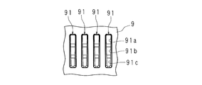
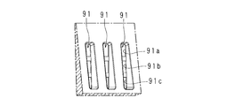
- FIG. 11 is a front view showing a part of the inclined portion of the rear surface of the rear cabinet of the conventional liquid crystal display device
- FIG. 12 is a schematic perspective view showing a part of the inclined portion of the rear cabinet
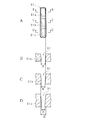
- FIG. 13A is formed in the inclined portion
- 13B is a sectional view taken along the line BB in FIG. 13A
- FIG. 13C is a sectional view taken along the line CC in FIG. 13A
- FIG. 13D is a sectional view taken along the line DD in FIG.
- the rear cabinet 9 has an inclined portion on the back surface, and a plurality of concave portions 91 recessed inward are arranged in the horizontal direction in the inclined portion.
- the recess 91 has a rectangular shape in which the opening surface has a uniform lateral width, and the side surface has a tapered shape inclined with respect to the peripheral edge of the opening. And the hole 91a, 91b, 91c is arranged in the vertical direction in the bottom face of the recessed part 91. As shown in FIG.
- the recess 91 is inclined at a certain angle from each position in the circumferential direction of the peripheral edge of the opening toward the edge of the bottom surface. This inclination is a draft provided for extraction from the molding die.
- the gradient of the side surface of the concave portion 91 with respect to the opening peripheral edge portion is constant with respect to the circumferential position of the side surface, the larger the distance in the depth direction between the bottom surface and the opening peripheral edge portion, The width is shortened. That is, the lateral width of the bottom surface gradually decreases from the hole 91a side to the hole 91c side, and the bottom surface becomes trapezoidal. Therefore, the heat dissipation effect on the hole 91c side is reduced.
- the opening surface has a rectangular shape with a uniform lateral width, whereas the bottom surface has a trapezoidal shape as described above, so the appearance of the rear cabinet 9 is poor.
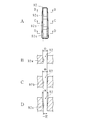
- FIG. 14A is a front view showing a recess having another configuration
- FIG. 14B is a sectional view taken along line BB in FIG. 14A
- FIG. 14C is a sectional view taken along line CC in FIG. 14A
- the bottom surface of the recess 92 has a rectangular shape with a uniform lateral width.
- the recess 92 is formed using a mold configured to take a draft angle at a constant angle from the edge of the bottom surface toward the peripheral edge of the opening, and the gradient of the side surface with respect to the edge of the bottom surface is Since it is constant with respect to the direction position, the lateral width of the opening increases as the distance in the depth direction between the bottom surface of the recess 92 and the peripheral edge of the opening increases.
- the lateral width of the opening gradually increases from the hole 92a side to the hole 92c side, and the opening surface becomes trapezoidal.
- the bottom surface has a rectangular shape with a uniform lateral width
- the opening surface has a trapezoidal shape, the appearance is deteriorated, and it is necessary to increase the pitch when the concave portions 92 are arranged side by side, The heat dissipation effect is reduced.
- the lateral width of the bottom surface gradually decreases, and in the case of the concave portion 92, the opening surface has a trapezoidal shape, and the side-by-side pitch of the concave portions 92 is larger than that of the rectangular shape.
- the heat radiation efficiency is poor in any case.
- the bottom surface or the opening surface of the recess has a trapezoidal shape, the appearance deteriorates.
- the shape and size of the bottom surface and the opening surface of the recesses arranged in the lateral direction are not uniform, the appearance is deteriorated.
- it is conceivable to provide the hole while avoiding the inclined part or the curved part but in this case, the range in which the hole is provided is limited, and the heat dissipation efficiency is deteriorated.
- the present invention has been made in view of such circumstances, and the shape of the bottom surface and the opening surface of the concave portion provided on the inclined surface or curved surface of the bottom surface can be made the same while suppressing the ingress of water.
- a housing that can be arranged in parallel at a constant pitch, has a high heat radiation efficiency combined with a high degree of freedom in arranging the recesses, and has a good appearance, a display device including the housing, and the display
- An object is to provide a television receiver including the apparatus.
- the housing according to the present invention has a first opening, has an inclined surface or a curved surface outside the first bottom surface facing the first opening, and is recessed inside the inclined surface or curved surface.
- the housing having a plurality of recesses, and a hole is provided in the second bottom surface of the recess the peripheral surface of each recess is inclined with respect to the peripheral edge of the second opening of the recess, The gradient of the peripheral surface with respect to the peripheral portion is different according to the circumferential position of the peripheral surface.
- the housing according to the present invention is characterized in that the gradient is larger as the distance between the second opening and the second bottom surface is shorter.
- the housing according to the present invention is characterized in that the second bottom surface is substantially parallel to the surface of the first opening.
- the housing according to the present invention is characterized in that the surface of the second opening and the second bottom surface are rectangular.
- a display device includes a display unit and any one of the above-described housings covering the display unit.
- a television receiver includes the above-described display device and a receiving unit that receives a television broadcast, and displays an image on the display device based on the television broadcast received by the receiving unit. It is characterized by the above.
- the shape of the bottom surface and the opening surface of the recess can be made the same. Therefore, heat can be uniformly dissipated from the bottom surface of the recess toward the opening surface. Further, the shape and size of the bottom surface and the opening surface of the recesses can be made uniform between the recesses arranged side by side in the lateral direction, the pitch of the arrangement can be made uniform, and a large number of recesses can be provided. Then, the shape, size, and pitch of the recesses can be optimized, and coupled with the high degree of freedom in arranging the recesses, the heat dissipation efficiency can be improved. Furthermore, since the shape and size of the recess can be made uniform, the appearance is good. Moreover, not only the inclined surface inclined in one direction but also the curved surface having a complicated shape can be provided with a concave portion without breaking the shape of the bottom surface and the opening surface of the concave portion. Can be designed.
- FIG. 10A is a front view of the recess
- FIG. 10B is a cross-sectional view taken along line BB of FIG. 10A
- FIG. 10C is a cross-sectional view taken along line CC of FIG. 10A
- FIG. 10A is a front view of the recess
- FIG. 10B is a cross-sectional view taken along line BB of FIG. 10A
- FIG. 10C is a cross-sectional view taken along line CC of FIG. 10A
- FIG. 10A is a front view of the recess
- FIG. 10B is a cross-sectional view taken along line BB of FIG. 10A
- FIG. 10C is a cross-sectional view taken along line CC of FIG. 10A
- FIG. 10A is a front view of the recess
- FIG. 10B is a cross-sectional view taken along line BB of FIG. 10A
- FIG. 10C is a cross-sectional view taken along line CC of FIG. 10A
- FIG. 13A is a front view of a recess formed in an inclined portion
- FIG. 13B is a cross-sectional view taken along line BB in FIG. 13A
- FIG. 13C is a cross-sectional view taken along line CC in FIG. 13A
- FIG. 14A is a front view showing a recess having another configuration
- FIG. 14B is a sectional view taken along line BB in FIG. 14A
- FIG. 14C is a sectional view taken along line CC in FIG. 14A
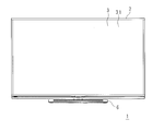
- FIG. 1 is a perspective view schematically showing a TV receiver 1 according to an embodiment of the present invention
- FIG. 2 is a front view of the TV receiver 1
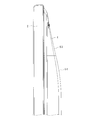
- FIG. 3 is a side view of the TV receiver 1
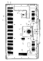
- FIG. 5 is a partially enlarged back view showing a rear cabinet 4 included in the TV receiver 1
- FIG. 6 is a partially enlarged side view of the TV receiver 1
- FIG. 7 is a rear cabinet of the TV receiver 1.
- 4 is a partial cross-sectional view of (housing) 4.
- the TV receiver 1 includes a display panel 31 and a backlight unit (not shown), has a horizontally long rectangular parallelepiped shape, and is a vertically placed display module 3 and a front cabinet that covers the front edge and side surfaces of the display module 3. 2, a rear cabinet 4 that covers the back of the display module 3, a stand 6 that supports the display module 3, a tuner (receiver) 7 that receives broadcast waves from an antenna (not shown), and encoded broadcast waves And a decoder 8 for decoding.
- a tuner (receiver) 7 that receives broadcast waves from an antenna (not shown), and encoded broadcast waves
- a decoder 8 for decoding.
- the backlight unit of the display module 3 includes a rectangular light guide plate, an optical sheet, and an LED substrate in a rectangular box-shaped chassis.
- the LED substrate is formed by mounting a plurality of LEDs on the plane of a substrate having an elongated rectangular plate shape.
- the light guide plate is placed on the bottom plate of the chassis, and the LED substrate is disposed on the long side surface on the upper side of the light guide plate.
- On the outer surface of the bottom plate of the chassis a main board on which the above-described tuner 7 and decoder 8 are mounted is provided, and the main board is covered with a cover.
- An optical sheet is placed on the light guide plate, and a display panel 31 is placed on the optical sheet to constitute the display module 3.
- the front cabinet 2 is made of, for example, aluminum and has a horizontally long rectangular frame shape.
- the rear cabinet 4 is made of, for example, a synthetic resin, and has an opening (first opening) 4a, a bottom surface (first bottom surface) 4b facing the opening 4a, and a side surface 4c provided around the bottom surface 4b. And has a box shape.
- an inclined portion (inclined surface) 53 inclined with respect to the opening 4a between the upper end portion of the bottom surface of the rear cabinet 4 and a lower side of about one fifth in the height direction.
- a curved portion (curved surface) 54 that is connected to the inclined portion 53 and gently curved is provided.
- a small box-like cover 51 is projected below the central portion in the lateral direction of the rear cabinet 4.
- the inclined portion 53 faces the LED substrate of the display module 3, and the cover portion 51 is arranged to face the main substrate.
- the rear cabinet 4 has two terminal panels provided with an input terminal, an output terminal, an antenna input terminal, a USB terminal, a headphone terminal, a B-CAS card insertion slot, etc. on one short side (right side in FIG. 2). 52.
- the rear cabinet 4 includes an inclined portion 53 and a curved portion 54, a central portion on the other short side, one side of the upper portion of the cover portion 51, both sides below the cover portion 51, and a lower portion of the central portion of the cover portion 51.
- Each of the heat radiating portions 40, 46, 47, 48, 49, 50 has a plurality of concave portions recessed inwardly and horizontally, and a plurality of holes are provided in the bottom surface (second bottom surface) of each concave portion.
- the heat radiating portion 40 has concave portions 41, 42 that are recessed inward in order from a position slightly below the upper end portion of the inclined portion 53, and are rectangular in front view. 43, 44 and 45 are provided.
- the lengths of the recesses 41, 42, 43, 44, 45 are shorter in this order, that is, the lengths of the recesses are gradually longer along the inclination direction.
- a plurality of the concave portions 41, 42, 43, 44, 45 are arranged side by side in the lateral direction.
- the bottom surface of the recess 41 is provided with rectangular holes 41a and 41b.
- the lower surface of the inner wall of the recess 41 is longer in depth than the upper surface, and the side surface is substantially trapezoidal.
- the lengths of the holes 41a and 41b are equal.
- the side surface of the concave portion 41 has a draft, and the angle of the opening (second opening) 41c with this gradient gradually decreases downward as in the concave portion 43 described later.
- the lateral width of the bottom surface of the recess 41 and the surface of the opening 41c is uniform, and the bottom surface and the opening surface are both rectangular.
- a recess 42 is provided at a slight distance from the recess 41 in the downward direction.
- the bottom surface of the recess 42 is provided with holes 42a and 42b having the same length as the hole 41a.
- the slope of the side surface of the recess 42 with respect to the peripheral edge portion of the opening 42 c gradually decreases in the downward direction, like the recess 43. Therefore, both the bottom surface and the surface of the opening 42c are rectangular.
- a concave portion 43 is provided in a curved portion 54 that is slightly spaced downward from the concave portion 42. Holes 43a, 43b, and 43c having the same length as the hole 41a are provided on the bottom surface of the recess 43.
- the gradient of the side surface of the recess 43 with respect to the peripheral portion of the opening 43d gradually decreases in the downward direction, such as 9 °, 6 °, 4.5 °, 3.5 °, and 3 °. Therefore, both the bottom surface and the surface of the opening 43d are rectangular.
- a recess 44 is provided at a slight distance from the recess 43 in the downward direction. Holes 44a, 44b, 44c, and 44d having the same length as the hole 41a are provided on the bottom surface of the recess 44.
- the slope of the side surface of the recess 44 with respect to the peripheral edge of the opening 44e gradually decreases in the downward direction like the recess 43. Accordingly, the bottom surface and the surface of the opening 44e are both rectangular.
- a recess 45 is provided at a slight distance from the recess 44 in the downward direction. Holes 45a, 45b, 45c, and 45d having the same length as the hole 41a are provided on the bottom surface of the recess 45.
- the slope of the side surface of the recess 45 with respect to the peripheral edge of the opening 45e gradually decreases in the downward direction, like the recess 43. Therefore, both the bottom surface and the surface of the opening 45e are rectangular.
- FIG. 8 is a schematic perspective view showing the recess 43
- FIG. 9 is a schematic cross-sectional view of the recess 43
- FIG. 10A is a front view of the recess 43
- FIG. 10B is a cross-sectional view taken along line BB of FIG. 10A
- FIG. 10D is a sectional view taken along the line DD of FIG. 10A.
- the recess 43 has a vertical position on the side surface of the recess 43 so that the width of the surface of the opening 43d of the recess 43 is constant and the width of the holes 43a, 43b, 43c is constant. Are formed using a mold whose draft is determined.
- the gradient of the side surface with respect to the opening peripheral edge portion gradually decreases downward, and the side surface is inclined from the opening peripheral edge portion toward the outer surface of the hole so that the surface and the bottom surface of the opening 43d form a rectangular shape. It will be.
- the other concave portions 41, 42, 44, 45 are formed by changing the gradient of the side surface with respect to the peripheral edge of the opening according to the vertical position of the side surface so that the lateral width of the opening surface and the bottom surface becomes uniform. Therefore, the shape and size of the bottom surface and the opening surface can be made uniform between the recesses 41, between the recesses 42, between the recesses 43, between the recesses 44, and between the recesses 45, respectively. And as shown in this Embodiment, the shape and magnitude
- the row of the recesses 41 and the row of the recesses 43 have portions where the arrangement of the holes on the bottom surface is different from the others. May be changed. Also in this case, the lateral widths of the opening surface and the bottom surface of the recess can be made uniform. Further, when the other heat radiating portions 46, 47, 48, 49, 50 are also formed on an inclined surface or a curved surface, similarly, the opening peripheral portion of the side surface is set so that the lateral width of the opening surface and the bottom surface is uniform. The gradient is changed according to the vertical position of the side surface.
- the concave portions 41, 42, 43, 44, 45 provided in the inclined portion 53 or the curved portion 54 have the lower surface of the inner wall of the concave portion 41 from the upper surface. Since the depth length is long and the side surface has a substantially trapezoidal shape, when water enters, the water stays on the bottom surface, and the intrusion into the inside is well suppressed.
- the width of each of the bottom surface and the opening surface is constant and the bottom surface and the opening surface are rectangular, the heat generated from the LED substrate or the like can be uniformly dissipated from the bottom surface toward the opening surface. Further, the pitch in the horizontal direction can be taken as in the case where the concave portion having the rectangular opening surface is provided in the flat portion, and a large number of concave portions can be provided, and the heat radiation efficiency is good. Moreover, since the shape of a recessed part is uniform, an external appearance is favorable.
- the rear cabinet 4 can be designed. And since a recessed part can be provided in any surface of a plane, an inclined surface, and a curved surface, there is no restriction
- the cabinet 4 can be provided with a heat radiating portion, and the heat radiation efficiency is improved.
- the housing (rear cabinet 4) has the first opening (4a), and the inclined surface (53) or the outer side of the bottom surface (4b) facing the first opening. It has a curved surface (54), has a plurality of concave portions (41, 42, 43, 44, 45) recessed inwardly on the inclined surface or curved surface, and holes (41a, 42a) on the second bottom surface of the concave portion , 43a, 44a, 45a, etc.), the peripheral surface of each recess is inclined with respect to the peripheral edge of the opening (41c, 42c, 43d, 44e, 45e) of the recess, The gradient of the peripheral surface with respect to the peripheral edge portion is different according to the circumferential position of the peripheral surface.
- the shape of the bottom surface and the opening surface of the recess can be made the same. Therefore, heat can be uniformly radiated from the bottom surface toward the opening surface. Further, the shape and size of the bottom surface and the opening surface of the recesses can be made uniform between the recesses arranged side by side in the lateral direction, the pitch of the arrangement can be made uniform, and a large number of recesses can be provided. Since the shape, size, and pitch of the recesses can be optimized, the recesses can be provided without limitation on any part of the housing such as a flat surface and an inclined surface, and the degree of freedom of arrangement of the recesses is high. In combination, the heat dissipation efficiency can be improved.
- the casing (4) according to the present invention is characterized in that the gradient is larger as the distance between the second opening and the second bottom surface is shorter.
- the shape of the bottom surface and the opening surface of the recess can be easily and reliably made the same.
- the housing (4) according to the present invention is characterized in that the second bottom surface is substantially parallel to the surface of the first opening.
- the ingress of water is more effectively suppressed.
- the housing (4) according to the present invention is characterized in that the surface and the bottom surface of the second opening are rectangular.
- the bottom surface and the opening surface are rectangular, and the lateral widths of the bottom surface and the opening surface are uniform, so that heat can be uniformly dissipated in the direction in which the recess extends.
- a recessed part can be arranged side by side effectively in length and breadth, heat dissipation efficiency becomes more favorable, and an external appearance becomes more favorable.
- a display device includes a display unit (3) and any one of the above-described casings (4) covering the display unit.
- the present invention it is possible to improve the heat dissipation and appearance of the housing of the display device having a complicated bottom shape in order to reduce the thickness and size.
- a TV receiver (1) includes the display device described above and a receiving unit (7) that receives a television broadcast, and the display device is based on the television broadcast received by the receiving unit. An image is displayed on the screen.
- the present invention it is possible to reduce the thickness and size, and to improve the heat dissipation and appearance of the housing of the TV receiver having a complicated bottom shape.
- the opening surface and the bottom surface of the recesses (41, 42, 43, 44, 45) are rectangular has been described, but the present invention is not limited to this.
- the surface and the bottom surface can have other shapes. Regardless of the shape, according to the present invention, the shape and size of the opening surface and the bottom surface of the recess can be made uniform between the recesses.
- the casing of the present invention is applied to the rear cabinet 4 of the TV receiver.
- the present invention is not limited to this, and the present invention is not limited to this. It is possible to apply to the housing
Landscapes
- Engineering & Computer Science (AREA)
- Physics & Mathematics (AREA)
- Thermal Sciences (AREA)
- Microelectronics & Electronic Packaging (AREA)
- Multimedia (AREA)
- Signal Processing (AREA)
- Devices For Indicating Variable Information By Combining Individual Elements (AREA)
- Planar Illumination Modules (AREA)
- Cooling Or The Like Of Electrical Apparatus (AREA)
- Liquid Crystal (AREA)
Abstract
水の浸入を抑制しつつ、底面の傾斜面又は湾曲面に設ける凹部の底面及び開口面の形状を同一にすることができ、凹部を一定のピッチで多数並設することができ、凹部の配置の自由度が高いことと相まって放熱効率が良好であり、かつ外観が良好である筐体、該筐体を備える表示装置、及び該表示装置を備えるテレビジョン受信機を提供する。 TV受信機のリアキャビネット4の底面の上端部から高さ方向の略5分の1下側までの部分は、開口4aに対し傾斜した傾斜部分と湾曲部分とからなる。傾斜部分の上端部から下側へ順に、内側に凹み、正面視が矩形状をなす凹部41、42、43、44、45が設けられている。凹部41等の底面には孔41a,41b等が設けられ、凹部41等の内壁の下面は上面より奥行き長さが長くなっており、側面は略台形状をなす。凹部41等の側面の開口周縁部に対する勾配は、側面の上下方向位置に対応して異なる。
Description
本発明は、電気機器等の発熱体から生じる熱を放熱する放熱孔を有する筐体、該筐体と表示部とを備える表示装置、該表示装置を備えるテレビジョン受信機に関する。
近年、液晶表示装置等の表示装置の性能、品位が向上し、外観的にも薄型化、軽量化、狭額縁化が進行している。液晶表示装置は、テレビジョン受信機(以下、TV受信機という)の映像表示装置として幅広く用いられている。液晶表示装置は、自己発光型のデバイスとは異なり、光源としてのバックライトを必要とし、液晶の電気光学特性により決まる光透過率を制御して映像を表示する。
バックライトにはエッジライト方式(サイドライト方式、導光板方式)と直下型方式とがある。近年、液晶表示装置の薄型化、軽量化、狭額縁化を実現するために、エッジライト方式が広く採用されている。エッジライト方式のバックライトを備える液晶表示装置の場合、矩形箱状をなすシャーシに、矩形状をなす導光板、光学シート、及びLED基板を収納してバックライトユニットが構成される。LED基板は、細長い基板の平面に、複数のLEDを実装してなる。バックライトユニットが片側のエッジライト型である場合、LED基板は導光板の一方の長側面側に配され、両側のエッジライト型である場合、LED基板は導光板の両方の長側面側に配される。
縦姿勢に配したバックライトユニットの正面に矩形板状をなす液晶表示パネル(以下、表示パネルという)を配し、表示パネルの正面縁部及び側面をフロントキャビネットで覆い、バックライトユニットの背面を矩形箱状をなすリアキャビネット(筐体)で覆うことにより、液晶表示装置が得られる。液晶表示装置において、LEDから発光し、導光板の長側面に入射した光は導光板の主面から出射して、表示パネルの背面を照射する。
以上のように構成された液晶表示装置においては、LED基板の配置部等で集中的に熱が発生する。筐体内に熱が籠もった場合、内部の部品に不具合が生じる虞があるため、筐体の背面に孔を設けて放熱する必要がある。近年、大画面化、高精細化のためLEDの投入電力が増加し、発熱量が増えたため、放熱性の重要度が増している。
特許文献1には、放熱のために、リアキャビネットの底面に長方形状をなす孔を複数設ける場合に、孔の下面を、内側から外側に傾斜したテーパ状に形成することが開示されている。特許文献1に係る発明の場合、水の内部への浸入が抑制されているが、孔の内側の上下方向長さが外側の上下方向長さより短くなっており、放熱効率が悪く、外観が悪いという問題があった。
近年、液晶表示装置を薄型化するために、リアキャビネットの箱深さを浅くしている。同じ薄さでもリアキャビネットの形状によって受ける印象が大きく異なり、より薄く見えるものが好まれる。リアキャビネットをより薄く見せるために、最薄部と最厚部とを曲面又は傾斜面で結ぶデザインが採用されている。しかし、リアキャビネットの傾斜部分等に、傾斜方向に延び、LED基板等からの熱を放熱する孔を設ける場合、平面部分に設ける場合と同様に面方向に延びるように設けることにすると、天面側から水をこぼしたときに表示装置の内部に水が浸入する虞があり、故障及び発火の原因となることがあるという問題があった。
リアキャビネットの背面の平面部分ではなく、傾斜部分に孔を設ける場合に、天面側からの水の浸入を防止するために、従来、傾斜部分に内側に凹んだ凹部を設け、その底面に孔を設けることもなされていた。しかし、この場合、以下のように、凹部の底面から筐体の外面までの距離(深さ)が、凹部の周面の周方向位置によって異なるので、凹部の底面又は開口面の横幅が上下方向に不均一になるという問題があった。
図11は従来の液晶表示装置のリアキャビネットの背面の傾斜部分の一部を示す正面図、図12はリアキャビネットの傾斜部分の一部を示す模式的斜視図、図13Aは傾斜部分に形成された凹部の正面図、図13Bは図13AのB-B線断面図、図13Cは図13AのC-C線断面図、図13Dは図13AのD-D線断面図である。リアキャビネット9は背面に傾斜部分を有し、傾斜部分には、内側に凹んだ凹部91が横方向に複数並設されている。凹部91は開口面が横幅が均一である矩形状をなし、側面は開口周縁部に対して傾斜したテーパ状をなしている。そして、凹部91の底面には孔91a,91b,91cが縦方向に並設されている。
凹部91は、開口周縁部の周方向の各位置から底面の縁部に向けて、一定の角度で傾斜している。この傾斜は、成型用金型からの抜き出しのために設けた抜き勾配である。図13に示すように、凹部91の側面の開口周縁部に対する勾配が側面の周方向位置に対して一定であるので、底面と開口周縁部との深さ方向の距離が大きくなる程、孔の横幅が短くなる。すなわち、孔91a側から孔91c側へ向けて漸次的に底面の横幅が小さくなり、底面が台形状になる。従って、孔91c側の放熱効果が低減する。そして、開口面が、横幅が均一である矩形状をなすのに対し、上述のように底面が台形状であるので、リアキャビネット9の外観が悪い。
図14Aは他の構成の凹部を示す正面図、図14Bは図14AのB-B線断面図、図14Cは図14AのC-C線断面図、図14Dは図14AのD-D線断面図である。
凹部92の底面は、横幅が均一である矩形状をなしている。凹部92は、底面の縁部から開口周縁部に向けて一定の角度で抜き勾配を取るように構成された金型を用いて形成されており、底面の縁部に対する側面の勾配が側面の周方向位置に対して一定であるので、凹部92の底面と開口周縁部との深さ方向の距離が大きくなる程、開口の横幅が大きくなる。すなわち、孔92a側から孔92c側へ向けて漸次的に開口の横幅が大きくなり、開口面が台形状になる。底面が、横幅が均一である矩形状をなすのに対し、開口面が台形状をなすので、外観が悪くなるとともに、凹部92を横方向に並設する場合にピッチを大きく取る必要が生じ、放熱効果が低減する。
凹部92の底面は、横幅が均一である矩形状をなしている。凹部92は、底面の縁部から開口周縁部に向けて一定の角度で抜き勾配を取るように構成された金型を用いて形成されており、底面の縁部に対する側面の勾配が側面の周方向位置に対して一定であるので、凹部92の底面と開口周縁部との深さ方向の距離が大きくなる程、開口の横幅が大きくなる。すなわち、孔92a側から孔92c側へ向けて漸次的に開口の横幅が大きくなり、開口面が台形状になる。底面が、横幅が均一である矩形状をなすのに対し、開口面が台形状をなすので、外観が悪くなるとともに、凹部92を横方向に並設する場合にピッチを大きく取る必要が生じ、放熱効果が低減する。
以上のように、凹部91の場合、底面の横幅が漸次的に小さくなり、凹部92の場合、開口面が台形状をなし、長方形の場合と比較して凹部92の横方向の並設ピッチが大きくなり、凹部92を多数並設することができず、いずれの場合も放熱効率が悪いという問題があった。凹部の底面又は開口面が台形状をなす場合、外観が悪くなる。また、横方向に並ぶ凹部の底面及び開口面の形状及び大きさが不均一になる場合も外観が悪くなる。そして、傾斜部分又は湾曲部分を避けて孔を設けるということも考えられるが、この場合、孔を設ける範囲が制限されることになり、放熱効率が悪くなる。
本発明は斯かる事情に鑑みてなされたものであり、水の浸入を抑制しつつ、底面の傾斜面又は湾曲面に設ける凹部の底面及び開口面の形状を同一にすることができ、凹部を一定のピッチで多数並設することができ、凹部の配置の自由度が高いことと相まって放熱効率が良好であり、かつ外観が良好である筐体、該筐体を備える表示装置、及び該表示装置を備えるテレビジョン受信機を提供することを目的とする。
本発明に係る筐体は、第1の開口を有し、該第1の開口に対向する第1の底面の外側に傾斜面又は湾曲面を有し、該傾斜面又は湾曲面に内側に凹んだ凹部を複数有し、該凹部の第2の底面に孔が設けられている筐体において、各凹部の周面は、該凹部の第2の開口の周縁部に対して傾斜しており、前記周面の前記周縁部に対する勾配は、前記周面の周方向位置に対応して異なることを特徴とする。
本発明に係る筐体は、前記勾配は、前記第2の開口と前記第2の底面との距離が短いほど、大きいことを特徴とする。
本発明に係る筐体は、前記第2の底面は前記第1の開口の面に略平行であることを特徴とする。
本発明に係る筐体は、前記第2の開口の面及び第2の底面は、矩形状をなすことを特徴とする。
本発明に係る表示装置は、表示部と、該表示部を覆う上述のいずれかの筐体とを備えることを特徴とする。
本発明に係るテレビジョン受信機は、上述の表示装置と、テレビジョン放送を受信する受信部とを備え、前記受信部にて受信したテレビジョン放送に基づいて、前記表示装置に映像を表示するようにしてあることを特徴とする。
本発明によれば、凹部の底面及び開口面の形状を同一にすることができる。従って、凹部の底面から開口面に向けて均一に放熱することができる。また、凹部の底面及び開口面の形状及び大きさを、横方向に並設する凹部間で均一にすることができ、並設ピッチを均一にすることができ、凹部を多数設けることができる。そして、凹部の形状、大きさ、ピッチを最適化することができ、凹部の配置の自由度が高いことと相まって、放熱効率を向上させることができる。さらに、凹部の形状、大きさ等を均一にできるので、外観が良好である。また、一方向に傾斜する傾斜面のみならず、複雑な形状をなす湾曲面に対しても凹部の底面及び開口面の形状を崩すことなく、凹部を設けることができるので、より薄型感が得られる筐体を設計することができる。
以下、本発明をその実施の形態を示す図面に基づいて具体的に説明する。
図1は本発明の実施の形態に係るTV受信機1を模式的に示す斜視図、図2はTV受信機1の正面図、図3はTV受信機1の側面図、図4はTV受信機1の裏面図、図5はTV受信機1が備えるリアキャビネット4を示す一部拡大裏面図、図6はTV受信機1の一部拡大側面図、図7はTV受信機1のリアキャビネット(筐体)4の一部断面図である。
TV受信機1は、表示パネル31及びバックライトユニット(不図示)を含み、横長の直方体状であり、縦置きにされた表示モジュール3と、表示モジュール3の正面縁部及び側面を覆うフロントキャビネット2と、表示モジュール3の背面を覆うリアキャビネット4と、表示モジュール3を支持するスタンド6と、アンテナ(不図示)から放送波を受信するチューナ(受信部)7と、符号化された放送波を復号するデコーダ8とを備える。
図1は本発明の実施の形態に係るTV受信機1を模式的に示す斜視図、図2はTV受信機1の正面図、図3はTV受信機1の側面図、図4はTV受信機1の裏面図、図5はTV受信機1が備えるリアキャビネット4を示す一部拡大裏面図、図6はTV受信機1の一部拡大側面図、図7はTV受信機1のリアキャビネット(筐体)4の一部断面図である。
TV受信機1は、表示パネル31及びバックライトユニット(不図示)を含み、横長の直方体状であり、縦置きにされた表示モジュール3と、表示モジュール3の正面縁部及び側面を覆うフロントキャビネット2と、表示モジュール3の背面を覆うリアキャビネット4と、表示モジュール3を支持するスタンド6と、アンテナ(不図示)から放送波を受信するチューナ(受信部)7と、符号化された放送波を復号するデコーダ8とを備える。
表示モジュール3のバックライトユニットは矩形箱状をなすシャーシに、矩形板状をなす導光板、光学シート、及びLED基板を収納してなる。LED基板は、細長い矩形板状をなす基板の平面に、複数のLEDを実装してなる。導光板がシャーシの底板に載置され、LED基板が導光板の上側の長側面側に配されている。シャーシの底板の外面には、上述のチューナ7及びデコーダ8等を実装したメイン基板が設けられており、メイン基板はカバーで覆われている。導光板に光学シートが載置され、光学シートに表示パネル31が載置されて表示モジュール3が構成されている。フロントキャビネット2は例えばアルミニウム製であり、横長の矩形枠状をなす。
図7に示すように、リアキャビネット4は例えば合成樹脂製であり、開口(第1の開口)4a、これに対向する底面(第1の底面)4b、及び底面4bに周設された側面4cとを有する箱状をなす。図3及び図6に示すように、リアキャビネット4の底面の上端部から高さ方向の略5分の1下側までの間には、開口4aに対し傾斜した傾斜部分(傾斜面)53と、傾斜部分53に連なり、緩やかに湾曲した湾曲部分(湾曲面)54とが設けてある。そして、リアキャビネット4の横方向中央部の下寄りには、小箱状のカバー部51が突設されている。傾斜部分53は表示モジュール3のLED基板に対向し、カバー部51は前記メイン基板に対向するように配置されている。
リアキャビネット4は、一方の短辺側(図2の右側)に、入力端子、出力端子、アンテナ入力端子、USB端子、ヘッドホン端子、及びB-CASカード挿入口等が設けられた2つの端子パネル52を備える。そして、リアキャビネット4は、傾斜部分53及び湾曲部分54、他方の短辺側の中央部、カバー部51の上部の一側方、カバー部51の下方の両側、及びカバー部51の中央部下寄りにそれぞれ、放熱部40、46、47、48,49、50を有する。各放熱部40、46、47、48,49、50は、内側に凹んだ凹部を縦横に複数有し、各凹部の底面(第2の底面)には複数の孔が設けられている。
図5及び図7に示すように、放熱部40には、傾斜部分53の上端部より少し下側の位置から下方向に順に、内側に凹み、正面視が矩形状をなす凹部41、42、43、44、45が設けられている。凹部41、42、43、44、45の長さは、この順に短い、すなわち、凹部の長さは傾斜方向に沿って次第に長くなっている。そして、各凹部41、42、43、44、45は横方向に複数並設されている。
凹部41の底面には、長方形状をなす孔41a,41bが設けられ、凹部41の内壁の下面は上面より奥行き長さが長くなっており、側面は略台形状をなす。孔41a,41bの長さは等しい。凹部41の側面は抜き勾配を有し、この勾配の開口(第2の開口)41cの周縁部に対する角度は、後述する凹部43と同様に、下方向に漸次的に小さくなっている。この結果、後述するように、凹部41の底面及び開口41cの面の横幅は均一になり、底面及び開口面ともに長方形状をなしている。
凹部41から下方向に少し間隔を隔てて、凹部42が設けられている。凹部42の底面には孔41aと長さが等しい孔42a,42bが設けられている。凹部42の側面の開口42cの周縁部に対する勾配は、凹部43と同様に、下方向に漸次的に小さくなっている。従って、底面及び開口42cの面ともに長方形状をなしている。
凹部42から下方向に少し間隔を隔てた湾曲部分54に凹部43が設けられている。凹部43の底面には孔41aと長さが等しい孔43a,43b,43cが設けられている。凹部43の側面の開口43dの周縁部に対する勾配は、下方向に9°、6°、4.5°、3.5°、3°というように漸次的に小さくなっている。従って、底面及び開口43dの面ともに長方形状をなしている。
凹部43から下方向に少し間隔を隔てて、凹部44が設けられている。凹部44の底面には孔41aと長さが等しい孔44a,44b,44c,44dが設けられている。凹部44の側面の開口44eの周縁部に対する勾配は、凹部43と同様に、下方向に漸次的に小さくなっている。従って、底面及び開口44eの面ともに長方形状をなしている。
凹部44から下方向に少し間隔を隔てて、凹部45が設けられている。凹部45の底面には孔41aと長さが等しい孔45a,45b,45c,45dが設けられている。凹部45の側面の開口45eの周縁部に対する勾配は、凹部43と同様に、下方向に漸次的に小さくなっている。従って、底面及び開口45eの面ともに長方形状をなしている。
図8は凹部43を示す模式的斜視図、図9は凹部43の模式的断面図、図10Aは凹部43の正面図、図10Bは図10AのB-B線断面図、図10Cは図10AのC-C線断面図、図10Dは図10AのD-D線断面図である。凹部43は、図10の細線で示すように、凹部43の開口43dの面の横幅が一定になり、孔43a,43b,43cの横幅が一定になるように、凹部43の側面の上下方向位置に対応して、抜き勾配を決定した金型を用いて形成されている。すなわち、凹部43は、側面の開口周縁部に対する勾配が下方向に次第に小さくなり、側面は、開口周縁部から孔の外面に向けて、開口43dの面及び底面が長方形状をなすように傾斜することになる。
他の凹部41、42、44、45も同様に、開口面及び底面の横幅が均一になるように、側面の開口周縁部に対する勾配を側面の上下方向位置に応じて変えて形成されている。従って、凹部41間、凹部42間、凹部43間、凹部44間、凹部45間でそれぞれ、底面及び開口面の形状及び大きさを均一にすることができる。そして、本実施の形態に示すように、異なる凹部41、42、43、44、45間で、孔41a、41b、42a、42b、・・・の形状及び大きさを均一にすることもできる。
なお、図5に示すように、凹部41の列及び凹部43の列には、底面の孔の配置が他と異なる部分があるが、このように、凹部の列内で一部の孔の配置を変えることにしてもよい。この場合も、凹部の開口面及び底面の横幅はそれぞれ均一にすることができる。また、他の放熱部46、47、48、49、50も傾斜面又は湾曲面に形成されている場合は、同様に、開口面及び底面の横幅が均一になるように、側面の開口周縁部に対する勾配を側面の上下方向位置に応じて変えて形成する。
以上のように構成された本実施の形態に係るTV受信機1においては、傾斜部分53又は湾曲部分54に設ける凹部41、42、43、44、45が、凹部41の内壁の下面が上面より奥行き長さが長くなっており、側面が略台形状をなすので、水が浸入した場合に水は下面に留まり、内部への浸入が良好に抑制されている。
そして、底面及び開口面の横幅がそれぞれ一定であり、底面及び開口面が長方形状をなすので、LED基板等から生じる熱を、底面から開口面に向けて均一に放熱することができる。また、開口面が長方形状をなす凹部を平面部に設ける場合と同様に横方向のピッチを取ることができ、凹部を多数設けることができ、放熱効率が良好である。また、凹部の形状が均一であるので、外観が良好である。さらに、一方向に傾斜する傾斜面のみならず、複雑な形状をなす曲面に対しても凹部の底面及び開口面の形状を崩すことなく、凹部を設けることができるので、より薄型感が得られるリアキャビネット4を設計することができる。そして、平面、傾斜面、及び湾曲面のいずれの面に対しても凹部を設けることができるので、放熱部を設ける範囲に制限がなく、表示モジュール3の複数の発熱部分に対応して、リアキャビネット4に放熱部を設けることができ、放熱効率が向上する。
以上のように、本発明に係る筐体(リアキャビネット4)は、第1の開口(4a)を有し、該第1の開口に対向する底面(4b)の外側に傾斜面(53)又は湾曲面(54)を有し、該傾斜面又は湾曲面に内側に凹んだ凹部(41、42、43、44、45)を複数有し、該凹部の第2の底面に孔(41a、42a、43a、44a、45a等)が設けられている筐体において、各凹部の周面は、該凹部の開口(41c、42c、43d、44e、45e)の周縁部に対して傾斜しており、前記周面の前記周縁部に対する勾配は、前記周面の周方向位置に対応して異なることを特徴とする。
本発明においては、凹部の底面及び開口面の形状を同一にすることができる。従って、底面から開口面に向けて均一に放熱することができる。また、凹部の底面及び開口面の形状及び大きさを、横方向に並設する凹部間で均一にすることができ、並設ピッチを均一にすることができ、凹部を多数設けることができる。凹部の形状、大きさ、ピッチを最適化することができるので、平面及び傾斜面等の筐体のいずれの部分にも制限なく凹部を設けることができ、凹部の配置の自由度が高いことと相まって、放熱効率を向上させることができる。そして、凹部の形状、大きさ等を均一にできるので、外観が良好である。また、一方向に傾斜する傾斜面のみならず、複雑な形状をなす湾曲面に対しても凹部の底面及び開口面の形状を崩すことなく、凹部を設けることができるので、より薄型感が得られる筐体を設計することができる。
本発明に係る筐体(4)は、前記勾配は、前記第2の開口と前記第2の底面との距離が短いほど、大きいことを特徴とする。
本発明においては、凹部の底面及び開口面の形状を容易に、かつ確実に同一にすることができる。
本発明に係る筐体(4)は、前記第2の底面は前記第1の開口の面に略平行であることを特徴とする。
本発明においては、水の浸入がより良好に抑制される。
本発明に係る筐体(4)は、前記第2の開口の面及び底面は、矩形状をなすことを特徴とする。
本発明においては、底面及び開口面が矩形状をなし、底面及び開口面の横幅がそれぞれ均一になるので、凹部が延びる方向に均一に放熱することができる。そして、凹部を縦横に有効に並設することができ、放熱効率がより良好になり、外観がより良好になる。
本発明に係る表示装置は、表示部(3)と、該表示部を覆う上述のいずれかの筐体(4)とを備えることを特徴とする。
本発明においては、薄型化、大型化を図るために複雑な底面形状を有する表示装置の筐体の放熱性及び外観を良好にすることができる。
本発明に係るTV受信機(1)は、上述の表示装置と、テレビジョン放送を受信する受信部(7)とを備え、前記受信部にて受信したテレビジョン放送に基づいて、前記表示装置に映像を表示するようにしてあることを特徴とする。
本発明においては、薄型化、大型化が図られ、複雑な底面形状を有するTV受信機の筐体の放熱性及び外観を良好にすることができる。
今回開示された実施の形態は、全ての点で例示であって、制限的なものではないと考えるべきである。本発明の範囲は、上述した意味ではなく、特許請求の範囲と均等の意味及び特許請求の範囲内での全ての変更が含まれることが意図される。
例えば、前記実施の形態においては、凹部(41、42、43、44、45)の開口面及び底面が長方形状をなす場合につき説明しているがこれに限定されるものではなく、凹部の開口面及び底面は他の形状を有することができる。いずれの形状であっても、本発明によれば、凹部の開口面及び底面の形状及び大きさを凹部間で均一にすることができる。
また、前記実施の形態においては、本発明の筐体をTV受信機のリアキャビネット4に適用した場合につき説明しているがこれに限定されるものではなく、本発明は、他の電気機器等の発熱体を覆う筐体に適用することが可能である。
1 TV受信機
2 フロントキャビネット
3 表示モジュール
31 表示パネル
4 リアキャビネット
4a 開口
4b 底面
4c 側面
40、46、47、48、49、50 放熱部
41、42、43、44、45 凹部
41a、41b、42a、42b、43a、43b、43c、44a、44b、44 c、44d、45a、45b、45c、45d 孔
41c、42c、43d、44e、45e 開口
53 傾斜部分
54 湾曲部分
6 スタンド
7 チューナ
8 デコーダ
2 フロントキャビネット
3 表示モジュール
31 表示パネル
4 リアキャビネット
4a 開口
4b 底面
4c 側面
40、46、47、48、49、50 放熱部
41、42、43、44、45 凹部
41a、41b、42a、42b、43a、43b、43c、44a、44b、44 c、44d、45a、45b、45c、45d 孔
41c、42c、43d、44e、45e 開口
53 傾斜部分
54 湾曲部分
6 スタンド
7 チューナ
8 デコーダ
Claims (6)
- 第1の開口を有し、該第1の開口に対向する第1の底面の外側に傾斜面又は湾曲面を有し、該傾斜面又は湾曲面に内側に凹んだ凹部を複数有し、該凹部の第2の底面に孔が設けられている筐体において、
各凹部の周面は、該凹部の第2の開口の周縁部に対して傾斜しており、
前記周面の前記周縁部に対する勾配は、前記周面の周方向位置に対応して異なることを特徴とする筐体。 - 前記勾配は、前記第2の開口と前記第2の底面との距離が短いほど、大きいことを特徴とする請求項1に記載の筐体。
- 前記第2の底面は前記第1の開口の面に略平行であることを特徴とする請求項1又は2に記載の筐体。
- 前記第2の開口の面及び第2の底面は、矩形状をなすことを特徴とする請求項3に記載の筐体。
- 表示部と、
該表示部を覆う請求項1から4までのいずれか一項に記載の筐体と
を備えることを特徴とする表示装置。 - 請求項5に記載の表示装置と、
テレビジョン放送を受信する受信部と
を備え、
前記受信部にて受信したテレビジョン放送に基づいて、前記表示装置に映像を表示するようにしてあることを特徴とするテレビジョン受信機。
Applications Claiming Priority (2)
| Application Number | Priority Date | Filing Date | Title |
|---|---|---|---|
| JP2013113381A JP5646689B2 (ja) | 2013-05-29 | 2013-05-29 | 筐体、表示装置、及びテレビジョン受信機 |
| JP2013-113381 | 2013-05-29 |
Publications (1)
| Publication Number | Publication Date |
|---|---|
| WO2014192764A1 true WO2014192764A1 (ja) | 2014-12-04 |
Family
ID=51988792
Family Applications (1)
| Application Number | Title | Priority Date | Filing Date |
|---|---|---|---|
| PCT/JP2014/064011 Ceased WO2014192764A1 (ja) | 2013-05-29 | 2014-05-27 | 筐体、表示装置、及びテレビジョン受信機 |
Country Status (2)
| Country | Link |
|---|---|
| JP (1) | JP5646689B2 (ja) |
| WO (1) | WO2014192764A1 (ja) |
Cited By (3)
| Publication number | Priority date | Publication date | Assignee | Title |
|---|---|---|---|---|
| US11219138B2 (en) | 2019-03-18 | 2022-01-04 | Nec Platforms, Ltd. | Heat dissipation structure |
| CN114180960A (zh) * | 2020-09-15 | 2022-03-15 | Oppo广东移动通信有限公司 | 壳体及其制备方法和电子设备 |
| CN114967239A (zh) * | 2022-07-29 | 2022-08-30 | 惠科股份有限公司 | 背光模组的背板、背光模组和显示装置 |
Families Citing this family (2)
| Publication number | Priority date | Publication date | Assignee | Title |
|---|---|---|---|---|
| WO2017159111A1 (ja) * | 2016-03-18 | 2017-09-21 | シャープ株式会社 | 表示装置及びテレビジョン受像機 |
| JP6198910B1 (ja) * | 2016-03-18 | 2017-09-20 | シャープ株式会社 | 表示装置及びテレビジョン受像機 |
Citations (2)
| Publication number | Priority date | Publication date | Assignee | Title |
|---|---|---|---|---|
| JPH0638146A (ja) * | 1992-07-21 | 1994-02-10 | Mitsubishi Electric Corp | 放熱穴付き機器用カバー |
| JP2010028719A (ja) * | 2008-07-24 | 2010-02-04 | Toshiba Corp | 電子装置カバー及びディスプレイ装置 |
Family Cites Families (1)
| Publication number | Priority date | Publication date | Assignee | Title |
|---|---|---|---|---|
| JP2011181742A (ja) * | 2010-03-02 | 2011-09-15 | Sony Corp | 電子機器 |
-
2013
- 2013-05-29 JP JP2013113381A patent/JP5646689B2/ja not_active Expired - Fee Related
-
2014
- 2014-05-27 WO PCT/JP2014/064011 patent/WO2014192764A1/ja not_active Ceased
Patent Citations (2)
| Publication number | Priority date | Publication date | Assignee | Title |
|---|---|---|---|---|
| JPH0638146A (ja) * | 1992-07-21 | 1994-02-10 | Mitsubishi Electric Corp | 放熱穴付き機器用カバー |
| JP2010028719A (ja) * | 2008-07-24 | 2010-02-04 | Toshiba Corp | 電子装置カバー及びディスプレイ装置 |
Cited By (4)
| Publication number | Priority date | Publication date | Assignee | Title |
|---|---|---|---|---|
| US11219138B2 (en) | 2019-03-18 | 2022-01-04 | Nec Platforms, Ltd. | Heat dissipation structure |
| CN114180960A (zh) * | 2020-09-15 | 2022-03-15 | Oppo广东移动通信有限公司 | 壳体及其制备方法和电子设备 |
| CN114967239A (zh) * | 2022-07-29 | 2022-08-30 | 惠科股份有限公司 | 背光模组的背板、背光模组和显示装置 |
| CN114967239B (zh) * | 2022-07-29 | 2022-11-25 | 惠科股份有限公司 | 背光模组的背板、背光模组和显示装置 |
Also Published As
| Publication number | Publication date |
|---|---|
| JP2014232231A (ja) | 2014-12-11 |
| JP5646689B2 (ja) | 2014-12-24 |
Similar Documents
| Publication | Publication Date | Title |
|---|---|---|
| JP5554870B1 (ja) | 液晶表示装置及び表示装置 | |
| US9270924B2 (en) | Television and electronic apparatus | |
| US9826654B2 (en) | Display | |
| JP5646689B2 (ja) | 筐体、表示装置、及びテレビジョン受信機 | |
| JP5508478B2 (ja) | 表示装置及びテレビジョン受信機 | |
| JP5841638B2 (ja) | 液晶表示装置及び表示装置 | |
| JP5166613B1 (ja) | 表示装置、及びテレビジョン受信機 | |
| JP2012138300A (ja) | テレビおよび電子機器 | |
| US20150177527A1 (en) | Apparatus for displaying three-dimensional image | |
| CN104471926A (zh) | 显示装置及电视接收器 | |
| US9632322B2 (en) | Display apparatus | |
| WO2013077243A1 (ja) | 照明装置、表示装置及びテレビ受信装置 | |
| WO2015050238A1 (ja) | 液晶表示装置 | |
| JP6259512B2 (ja) | 表示装置 | |
| US20110025922A1 (en) | Display device and frame body for display device | |
| JPWO2015159396A1 (ja) | 光源装置及び表示装置 | |
| WO2013191047A1 (ja) | 表示装置、及びテレビ受信装置 | |
| JP5926905B2 (ja) | 表示装置およびテレビジョン装置 | |
| JP5572571B2 (ja) | 表示装置及びテレビ受像機 | |
| WO2014007103A1 (ja) | 照明装置、表示装置、及びテレビ受信装置 | |
| JP2014179343A (ja) | バックライト装置及び液晶表示装置 | |
| JP2012037605A (ja) | 映像表示装置 | |
| JP2005196001A (ja) | 薄型表示装置 | |
| US10788620B2 (en) | Light emitting device, display apparatus, and substrate | |
| JP6168176B2 (ja) | 表示装置 |
Legal Events
| Date | Code | Title | Description |
|---|---|---|---|
| 121 | Ep: the epo has been informed by wipo that ep was designated in this application |
Ref document number: 14803995 Country of ref document: EP Kind code of ref document: A1 |
|
| NENP | Non-entry into the national phase |
Ref country code: DE |
|
| 122 | Ep: pct application non-entry in european phase |
Ref document number: 14803995 Country of ref document: EP Kind code of ref document: A1 |