WO2014192697A1 - 応力履歴測定方法および応力センサー - Google Patents
応力履歴測定方法および応力センサー Download PDFInfo
- Publication number
- WO2014192697A1 WO2014192697A1 PCT/JP2014/063845 JP2014063845W WO2014192697A1 WO 2014192697 A1 WO2014192697 A1 WO 2014192697A1 JP 2014063845 W JP2014063845 W JP 2014063845W WO 2014192697 A1 WO2014192697 A1 WO 2014192697A1
- Authority
- WO
- WIPO (PCT)
- Prior art keywords
- stress
- particles
- calcite
- calcite particles
- measured
- Prior art date
Links
- 238000000691 measurement method Methods 0.000 title claims abstract description 11
- 239000002245 particle Substances 0.000 claims abstract description 117
- 229910021532 Calcite Inorganic materials 0.000 claims abstract description 101
- 229920005989 resin Polymers 0.000 claims abstract description 13
- 239000011347 resin Substances 0.000 claims abstract description 13
- 238000000034 method Methods 0.000 claims description 20
- 239000013078 crystal Substances 0.000 claims description 19
- 238000007689 inspection Methods 0.000 claims description 14
- 238000005259 measurement Methods 0.000 abstract description 24
- 239000011230 binding agent Substances 0.000 description 6
- 239000003822 epoxy resin Substances 0.000 description 4
- 239000000463 material Substances 0.000 description 4
- 229920000647 polyepoxide Polymers 0.000 description 4
- 230000005489 elastic deformation Effects 0.000 description 3
- 230000003287 optical effect Effects 0.000 description 3
- 239000004576 sand Substances 0.000 description 3
- 238000004088 simulation Methods 0.000 description 3
- 239000004568 cement Substances 0.000 description 2
- 239000002131 composite material Substances 0.000 description 2
- 238000012669 compression test Methods 0.000 description 2
- 239000011162 core material Substances 0.000 description 2
- 230000006378 damage Effects 0.000 description 2
- 238000010586 diagram Methods 0.000 description 2
- 230000000694 effects Effects 0.000 description 2
- 238000011156 evaluation Methods 0.000 description 2
- 238000004519 manufacturing process Methods 0.000 description 2
- 238000012544 monitoring process Methods 0.000 description 2
- 238000005498 polishing Methods 0.000 description 2
- 238000012360 testing method Methods 0.000 description 2
- 208000010392 Bone Fractures Diseases 0.000 description 1
- 206010017076 Fracture Diseases 0.000 description 1
- 208000013201 Stress fracture Diseases 0.000 description 1
- 239000000470 constituent Substances 0.000 description 1
- 230000001066 destructive effect Effects 0.000 description 1
- 230000006866 deterioration Effects 0.000 description 1
- 238000002474 experimental method Methods 0.000 description 1
- 238000010191 image analysis Methods 0.000 description 1
- 238000012423 maintenance Methods 0.000 description 1
- 239000003550 marker Substances 0.000 description 1
- 238000011158 quantitative evaluation Methods 0.000 description 1
- 230000003014 reinforcing effect Effects 0.000 description 1
- 239000000126 substance Substances 0.000 description 1
- 230000002194 synthesizing effect Effects 0.000 description 1
- 238000010998 test method Methods 0.000 description 1
- 238000002834 transmittance Methods 0.000 description 1
Images

Classifications
-
- G—PHYSICS
- G01—MEASURING; TESTING
- G01N—INVESTIGATING OR ANALYSING MATERIALS BY DETERMINING THEIR CHEMICAL OR PHYSICAL PROPERTIES
- G01N33/00—Investigating or analysing materials by specific methods not covered by groups G01N1/00 - G01N31/00
- G01N33/39—Crystals
-
- G—PHYSICS
- G01—MEASURING; TESTING
- G01L—MEASURING FORCE, STRESS, TORQUE, WORK, MECHANICAL POWER, MECHANICAL EFFICIENCY, OR FLUID PRESSURE
- G01L5/00—Apparatus for, or methods of, measuring force, work, mechanical power, or torque, specially adapted for specific purposes
- G01L5/0047—Apparatus for, or methods of, measuring force, work, mechanical power, or torque, specially adapted for specific purposes measuring forces due to residual stresses
-
- G—PHYSICS
- G01—MEASURING; TESTING
- G01M—TESTING STATIC OR DYNAMIC BALANCE OF MACHINES OR STRUCTURES; TESTING OF STRUCTURES OR APPARATUS, NOT OTHERWISE PROVIDED FOR
- G01M5/00—Investigating the elasticity of structures, e.g. deflection of bridges or air-craft wings
- G01M5/0033—Investigating the elasticity of structures, e.g. deflection of bridges or air-craft wings by determining damage, crack or wear
-
- G—PHYSICS
- G01—MEASURING; TESTING
- G01N—INVESTIGATING OR ANALYSING MATERIALS BY DETERMINING THEIR CHEMICAL OR PHYSICAL PROPERTIES
- G01N33/00—Investigating or analysing materials by specific methods not covered by groups G01N1/00 - G01N31/00
- G01N33/38—Concrete; Lime; Mortar; Gypsum; Bricks; Ceramics; Glass
- G01N33/383—Concrete or cement
-
- G—PHYSICS
- G01—MEASURING; TESTING
- G01N—INVESTIGATING OR ANALYSING MATERIALS BY DETERMINING THEIR CHEMICAL OR PHYSICAL PROPERTIES
- G01N2203/00—Investigating strength properties of solid materials by application of mechanical stress
- G01N2203/02—Details not specific for a particular testing method
- G01N2203/0202—Control of the test
- G01N2203/0212—Theories, calculations
Definitions
- the present invention relates to a stress history measuring method and a stress sensor.
- a method of measuring the existing stress by installing a marker or sensor in advance see, for example, Patent Document 1
- a method of measuring the existing stress by installing a marker or sensor in advance see, for example, Patent Document 1
- a method of collecting a core and rebound amount or AE Kaiser A method of estimating from the effect (see, for example, Patent Document 2) is used.
- the stress of the concrete structure is estimated, for example, by estimating by simulation, or by correlating the predicted important points and estimating the maximum stress amount by acoustic emission (AE measurement). It is possible to analyze the history. However, neither method can be evaluated with high reliability. That is, in the estimation method by simulation, there is a problem that the result of the simulation becomes more ambiguous because the magnitude and direction of the external force that has suddenly acted out of the estimation range.
- the AE measurement since the AE measurement is performed by loading the core material on a mechanical testing machine and estimating the preceding maximum stress from the increase point of the microfracture sound, the AE measurement cannot obtain high accuracy.
- the AE measurement has a problem that since the maximum stress direction at the time of the event is not known, it is not a reproducible test, and since it is a destructive inspection, a large number of inspections cannot be performed on the entire structure.
- the present inventors mixed synthetic calcite serving as a stress index into an object to be measured in units of particles, and measured twin density for each calcite particle by a microscope.
- Patent Document 3 Japanese Patent Document 3
- JP 2004-101322 A JP-A-11-295198 Japanese Patent No. 4295334
- the present invention has been made on the basis of the circumstances as described above, and the purpose thereof is stress that can easily and accurately measure the stress history in the measurement object over a wide stress measurement range. It is to provide a history measuring method and a stress sensor.
- the stress history measurement method is a method for measuring an object to be measured that is subjected to an external force and is elastically deformed, in which stress sensors using a large number of calcite particles are embedded.
- the stress history received by the object to be measured is measured based on the ratio of calcite particles in which twin deformation has occurred.
- calcite particles that do not initially have twins.
- the stress history measurement method of the present invention it is preferable to use a material in which a large number of calcite particles are hardened with a resin as the stress sensor.
- At least a part of the object to be measured is an inspection object region, and among the calcite particles in which the crystal plane is exposed in the inspection object region, twins Based on the proportion of calcite particles in which deformation has occurred, the maximum stress acting on the entire object to be measured is estimated.
- the stress sensor of the present invention is characterized in that a large number of adjacent calcite particles are hardened by a resin in a state where the adjacent particles are in contact with each other.
- the stress history measurement method of the present invention it is only necessary to measure the proportion of calcite particles that have undergone twin deformation even after the external force applied to the object to be measured is released.
- anyone can easily and accurately measure the stress history of the measurement object, for example, the maximum stress.
- there is no restriction on the crystal size of calcite particles which is necessary if the method measures the twin density of calcite particles, and thus, for example, mass production is possible. Crystalline-sized synthetic calcite particles can be used.
- calcite particles that do not initially have twin deformation by using calcite particles that do not initially have twin deformation, a sufficiently large measurable range can be obtained, for example, even when the stress acting on the object to be measured is low, The stress history can be measured. Further, when measuring a portion where no stress is applied, it is not necessary to count twins at all, so that high efficiency can be obtained.
- calcite particles which is a set of resin in which a large number of adjacent calcite particles are in contact with each other. Since a large number of calcite particles can be secured, high reliability can be obtained in the measurement result, and measurement itself can be easily performed.
- FIG. 1 is a perspective view which shows the outline of the whole structure
- FIG. 1 is a schematic diagram which shows a particle structure. It is an idea figure which shows the state which the twin deformation generate
- An object to be measured according to the stress history measuring method of the present invention is a product or a structure made of concrete, for example, a composite material mainly composed of cement, and a stress sensor using a large number of calcite particles on the object to be measured. Is buried.
- FIG. 1 is an explanatory view showing an example of the stress sensor of the present invention.
- (A) is a perspective view which shows the outline of the whole structure
- (b) is a schematic diagram which shows a particle structure.
- the stress sensor 10 is configured by a large number of calcite particles (single crystals) 11 being solidified, for example, in a rectangular parallelepiped shape with a binder resin 12, and a grain support structure can be seen in the calcite particles 11. That is, in this stress sensor 10, adjacent calcite particles are in contact with or close to each other, and the tissue is held between the particles.
- the binder resin 12 constituting the stress sensor 10 is not particularly limited as long as it has the following characteristics.
- (A) It has fluidity before curing.
- (B) The volume shrinkage rate accompanying curing is small.
- examples of such a resin include an epoxy resin, specifically, an ultra-low viscosity epoxy resin “E205” (manufactured by NICHIKA CORPORATION) and the like.
- the calcite particles 11 are artificially synthesized even if they are natural (including those subjected to some stress event) as long as the presence or absence (initial state) of twin deformation is confirmed. However, it is preferable that it does not initially have twin deformation.
- synthetic calcite particles having no twin deformation are used as the calcite particles 11, the size of the calcite particles 11 is sufficiently large due to the measurement principle of detecting the proportion of calcite particles having twin deformation. A measurable range can be obtained. Therefore, for example, even a low stress of about several Mpa can be measured. Further, when measuring a portion where no stress is applied, it is not necessary to count twins at all, so that high efficiency can be obtained.
- the particle diameter (crystal size) of the calcite particles 11 is preferably in the range of, for example, 60 ⁇ m or more and 2000 ⁇ m or less, and specifically about 200 ⁇ m. This particle size is, for example, the same size as that of sand particles that are fine aggregates of concrete.
- particle diameter of calcite particles refers to a rectangular minor axis circumscribing the maximum projection plane.
- the content ratio of the calcite particles 11 is preferably 60 to 80 vol%, for example.
- 300 or more calcite particles having a particle diameter of 200 ⁇ m, for example, can be present in the measurement cross section in the region to be inspected, and the expected stress measurement (inspection) can be reliably performed with high reliability. It will be something that can be done.
- the stress sensor 10 can be manufactured as follows. That is, a predetermined amount of calcite particles 11 is filled into a mold under normal temperature and normal pressure, and then the binder resin 12 is filled into the mold under vacuum or reduced pressure. And said stress sensor 10 can be obtained by hardening the binder resin 12 under atmospheric pressure.
- the stress sensor 10 is configured as an aggregate of calcite particles, in which a large number of calcite particles 11 are hardened by a binder resin 12 in a state where adjacent particles are in contact with each other or close to each other. Therefore, according to the stress sensor 10, the number of calcite particles necessary for the measurement can be secured on the surface to be inspected, so that high reliability can be obtained in the measurement result and the measurement itself is easily performed. be able to.
- an external force including elastic force is applied to such an extent that an elastic deformation occurs without destroying the concrete product or the concrete structure itself.
- twins are formed on specific crystal planes of the calcite particles according to the magnitude of the external force.
- the twins formed in the calcite particles do not disappear even after the external force is released and the elastic deformation of the object to be measured is recovered, so that the calcite particles function as a microstress meter.
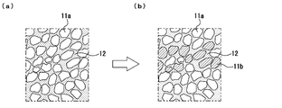
- 2A shows the initial state
- FIG. 2B shows the state after the external force is released.
- the twin deformation of calcite particles does not occur in all calcite particles, and calcite particles 11a that do not generate twin deformation and calcite particles 11b that generate twin deformation are mixed.
- a fracture strength for example, about 36 MPa
- the calcite particles 11 that cause twin deformation and the magnitude of the applied external force have a linear relationship. found. It was also found that the number of calcite particles in which twin deformation has occurred increases when the stress that has been subjected to any stress event has been exceeded. Therefore, by measuring the ratio of calcite particles in which twin deformation has occurred, the stress history, for example, the maximum stress, applied to the concrete product or concrete structure can be measured.
- the stress history measuring method will be specifically described.
- the stress sensor 10 is embedded in the measurement target, the stress sensor 10 is taken out from the measurement target, and the surface of the stress sensor 10 is measured. Is selected as the inspection target area.
- the stress sensor 10 is buried in the surface of the object to be measured, a part of the surface of the stress sensor 10 is selected as an inspection object region without taking the stress sensor 10 out of the object to be measured. .
- polishing the surface of the region to be inspected the crystal planes of the plurality of calcite particles are exposed to form an inspection surface.
- the size of one inspection target region is not particularly limited, and can be appropriately set according to the purpose.
- twin deformation is generated by detecting a change in light transmittance of the entire stress sensor 10 before an external force is applied (initial state) and after the external force is applied and released.
- twin deformation Based on the ratio of the generated calcite particles, it is possible to estimate the absolute value and distribution of stress applied to the entire object to be measured.
- calcite particles 11 that do not initially have twin deformation are used, a sufficiently large measurable range can be obtained.
- the stress acting on the object to be measured is low.
- the stress history can be measured. Further, when measuring a portion where no stress is applied, it is not necessary to count twins at all, so that high efficiency can be obtained.
- Example 1 About 0.5 g of single crystal synthetic calcite particles having no twin deformation is filled in a mold having a rectangular parallelepiped cavity of 5 mm ⁇ 5 mm ⁇ 10 mm.
- the particle diameter (crystal size) of the calcite particles is 200 ⁇ m, and the content ratio of the calcite particles is about 70 vol%.
- this mold was accommodated in a vacuum apparatus, and epoxy resin “E205” (manufactured by Nichika Co., Ltd.) was infiltrated into the gaps of the calcite particles under vacuum. The degree of vacuum was 1 kPa or less.
- a specimen according to the inventive stress sensor was produced.
- the field region of the optical microscope was ⁇ 10 mm, 300 or more calcite particles were present in the field region, and a grain support structure was observed in the calcite particles.
- the compressive strength of the specimen was measured by a uniaxial compression test in accordance with JIS 1108 (concrete compressive strength test method) except for the sample size, the compressive strength of the specimen was about 37 MPa. .
- the proportion of calcite particles having twin deformation in the unloaded state of the specimen obtained as described above was substantially 0%.
- the presence or absence of twin deformation of the calcite particles is confirmed by setting a part of the specimen to be inspected, polishing the surface to expose the crystal planes of a plurality of calcite particles, and using an optical microscope. This was done by observing the crystal plane. Then, the same uniaxial compression test as described above was performed by appropriately changing the load on the specimen, and the proportion of calcite particles in which twin deformation was generated relative to the magnitude of the load was examined. When a load of 15% (15 MPa) was applied, the proportion of calcite particles in which twin deformation occurred was 18%.
- calcite particles themselves mixed in the constituent material of the measurement target may be used as the stress sensor.
- calcite particles may be mixed in a dispersed state in place of a part of the aggregate, such as sand.
- the shape of the stress sensor is not limited to a rectangular parallelepiped shape, and can be appropriately changed according to the purpose.
- the shape of the stress sensor may be, for example, a spherical shape. In such a case, the stress sensor can be configured as having no anisotropy with respect to the direction of the stress.
- the present invention can be suitably applied to a concrete structure such as a structure in which stress is always generated, such as a dam or a power plant, a small bridge, a breakwater in a harbor, or a small structure such as an apartment. .
- the present invention is useful when performing quantitative evaluation of damage received by a small structure after receiving a force to such an extent that the structure does not break. Specifically, for example, when a small structure is subjected to an earthquake such as seismic intensity 5 or seismic intensity 6 to check whether the structure maintains a predetermined strength, or the structure itself
- the use of the present invention is expected to lead to an improvement in safety evaluation when monitoring local stress concentration accompanying deterioration of the material.
- the strength of the concrete itself can be measured.
- appropriate evaluation including the suitability of the concrete material itself can be performed.
Landscapes
- Chemical & Material Sciences (AREA)
- Engineering & Computer Science (AREA)
- Physics & Mathematics (AREA)
- Life Sciences & Earth Sciences (AREA)
- General Physics & Mathematics (AREA)
- Health & Medical Sciences (AREA)
- Biochemistry (AREA)
- Analytical Chemistry (AREA)
- Medicinal Chemistry (AREA)
- General Health & Medical Sciences (AREA)
- Food Science & Technology (AREA)
- Immunology (AREA)
- Pathology (AREA)
- Ceramic Engineering (AREA)
- Aviation & Aerospace Engineering (AREA)
- Investigating Strength Of Materials By Application Of Mechanical Stress (AREA)
- Crystallography & Structural Chemistry (AREA)
- Analysing Materials By The Use Of Radiation (AREA)
Abstract
本発明は、被測定対象物における応力履歴を、広い応力測定範囲にわたって、容易にかつ高精度に測定することのできる応力履歴測定方法および応力センサーを提供することを目的とする。 本発明の応力履歴測定方法においては、多数のカルサイト粒子による応力センサーが埋設された、外力を受けて弾性的に変形し得る被測定対象物について、被測定対象物が外力を受けた後における、双晶変形が生じたカルサイト粒子の割合に基づいて、被測定対象物が受けた応力履歴が測定される。応力センサーは、多数のカルサイト粒子が隣接する粒子同士が互いに接触した状態で樹脂により固められてなる。
Description
本発明は、応力履歴測定方法および応力センサーに関する。
現在、例えば、コンクリートにおける内部応力の測定方法としては、予めマーカーやセンサーになるものを設置しておき現有応力を測定する方法(例えば特許文献1参照)、あるいはコア採取してリバウンド量やAEカイザー効果から推定する方法(例えば特許文献2参照)などが利用されている。
而して、例えばコンクリート構造物に対して、地震および竜巻などの自然災害や、高速交通機関の衝突などの事故によって瞬間的に大きな力がかかっても、コンクリート構造物自体が破壊にまで至らず弾性的に変形するにとどまり、その後、外力が開放されて弾性変形が回復する場合には、コンクリート構造物が受けた力の大きさおよび分布が正確にわからないのが実情である。
このような場合においては、例えば、シミュレーションによる推定を行うことにより、あるいは、予想重要ポイントをコア採取し、それをアコースティックエミッション(AE測定)により最大応力量を推定することにより、コンクリート構造物の応力履歴を解析することが考えられる。しかしながら、いずれの方法によっても、高い信頼性をもって評価することができない。すなわち、シミュレーションによる推定方法においては、そもそも突発的に作用した外力の大きさと方向が推測の域を出ないので、シミュレーションの結果はより曖昧なものとなる、という問題がある。
また、AE測定は、コア材料を力学試験機に載荷し、その微小破壊音の増加点から先行最大応力を推定するものであるので、AE測定では、高い精度を得ることができない。しかも、AE測定では、イベント発生時の最大応力方向がわからないので再現試験にならないばかりか、破壊検査であるため、構造物全体であまり多数の検査を行うことができない、などの問題がある。
さらにまた、多数の歪み計をコンクリート構造物全体に設置し、常時モニタリングすることにより、コンクリート構造物における応力履歴を解析する方法も考えられる。しかしながら、このような方法は、通常の建築物では実際的ではなく、しかも、コンクリートに異物たるセンサーを埋包することは、不均質性を発生させることになるため、破壊の原因となり得る。
以上のような問題を解決するための手段として、本発明者らは、被測定対象物に応力指標となる合成カルサイトを粒子単位で混ぜ込み、カルサイト粒子1粒毎に双晶密度を顕微鏡によって測定する操作を、多数のカルサイト粒子について行い、これにより得られる双晶密度の平均値から被測定対象物の全体にかかった応力を推定する方法を提案している(特許文献3参照。)。
このような測定方法によれば、カルサイト結晶の特性を利用するのでメンテナンスの必要がなく、必要に応じて計測するだけなので現実的である。
このような測定方法によれば、カルサイト結晶の特性を利用するのでメンテナンスの必要がなく、必要に応じて計測するだけなので現実的である。
しかしながら、このような方法では、熟練した計測技術が必要な上に、多数のカルサイト粒子について計測を行うことが必要であり、非常に手間がかかる。
また、カルサイト粒子の双晶密度を測定するためには、カルサイト粒子に最低でも2対の双晶が生じていることが必要である。また、低い応力を検出しようとする場合には、例えばカルサイト粒子として例えば結晶サイズが1mmより大きいものを用いる必要があるといった結晶サイズについての制約があった。この理由は、作用した外力が小さいほど双晶間隔が広くなるためである。
しかも、結晶サイズが1mmより大きなカルサイト粒子を大量に合成することはまだ技術的に問題が残されているのが実情である。
また、カルサイト粒子の双晶密度を測定するためには、カルサイト粒子に最低でも2対の双晶が生じていることが必要である。また、低い応力を検出しようとする場合には、例えばカルサイト粒子として例えば結晶サイズが1mmより大きいものを用いる必要があるといった結晶サイズについての制約があった。この理由は、作用した外力が小さいほど双晶間隔が広くなるためである。
しかも、結晶サイズが1mmより大きなカルサイト粒子を大量に合成することはまだ技術的に問題が残されているのが実情である。
本発明は、以上のような事情に基づいてなされたものであって、その目的は、被測定対象物における応力履歴を、広い応力測定範囲にわたって、容易にかつ高精度に測定することのできる応力履歴測定方法および応力センサーを提供することにある。
本発明の応力履歴測定方法は、多数のカルサイト粒子による応力センサーが埋設された、外力を受けて弾性的に変形し得る被測定対象物について、当該被測定対象物が外力を受けた後における、双晶変形が生じたカルサイト粒子の割合に基づいて、当該被測定対象物が受けた応力履歴を測定することを特徴とする。
本発明の応力履歴測定方法においては、カルサイト粒子として、初生的に双晶を有さないものが用いられることが好ましい。
また、本発明の応力履歴測定方法においては、前記応力センサーとして、多数のカルサイト粒子が樹脂により固められてなるものが用いられることが好ましい。
さらにまた、本発明の応力履歴測定方法においては、被測定対象物における少なくとも一部の領域を検査対象領域として、当該検査対象領域において結晶面が露出された複数のカルサイト粒子のうち、双晶変形が生じたカルサイト粒子の割合に基づいて、被測定対象物全体に作用した最大応力が推定される。
本発明の応力センサーは、多数のカルサイト粒子が隣接する粒子同士が互いに接触した状態で樹脂により固められてなることを特徴とする。
本発明の応力履歴測定方法によれば、被測定対象物に作用された外力が開放された後においても残存する双晶変形の生じたカルサイト粒子の割合を測定しさえすればよいので、被測定対象物の応力履歴例えば最大応力を、誰にでも容易にかつ高精度に測定することができる。
また、双晶変形の有無を確認できればよいので、カルサイト粒子の双晶密度を測定する方法であれば必要となるカルサイト粒子の結晶サイズについての制約がなくなり、従って、例えば大量生産が可能な結晶サイズの合成カルサイト粒子を利用することができる。
また、双晶変形の有無を確認できればよいので、カルサイト粒子の双晶密度を測定する方法であれば必要となるカルサイト粒子の結晶サイズについての制約がなくなり、従って、例えば大量生産が可能な結晶サイズの合成カルサイト粒子を利用することができる。
また、初生的に双晶変形を有さないカルサイト粒子が用いられることにより、十分な大きさの測定可能範囲が得られ、例えば被測定対象物に作用した応力が低い場合であっても、当該応力履歴の測定が可能になる。また、応力が作用していない部分を測定する場合には、双晶を全くカウントしないですむので、高い効率が得られる。
さらにまた、応力センサーとして、多数のカルサイト粒子が隣接する粒子同士が互いに接触した状態で樹脂により固められてなる、いわばカルサイト粒子の集合体が用いられることにより、被検査面において測定に必要な数のカルサイト粒子を確保することができるので、測定結果に高い信頼性を得ることができると共に、測定自体を容易に行うことができる。
以下、本発明の実施の形態について詳細に説明する。
本発明の応力履歴測定方法に係る被測定対象物は、例えばセメントを主体とした複合材であるコンクリートからなる製品または構造物であって、当該被測定対象物に多数のカルサイト粒子による応力センサーが埋設される。
本発明の応力履歴測定方法に係る被測定対象物は、例えばセメントを主体とした複合材であるコンクリートからなる製品または構造物であって、当該被測定対象物に多数のカルサイト粒子による応力センサーが埋設される。
図1は、本発明の応力センサーの一例を示す説明図である。(a)は全体構成の概略を示す斜視図であり、(b)は粒子構造を示す模式図である。
この応力センサー10は、多数のカルサイト粒子(単結晶)11が、バインダー樹脂12によって例えば直方体状に固められて構成されており、カルサイト粒子11にグレインサポート組織が見られるものである。すなわち、この応力センサー10においては、隣接するカルサイト粒子が互いに接触ないし近接しており、粒子間で組織が保持された状態とされている。
この応力センサー10は、多数のカルサイト粒子(単結晶)11が、バインダー樹脂12によって例えば直方体状に固められて構成されており、カルサイト粒子11にグレインサポート組織が見られるものである。すなわち、この応力センサー10においては、隣接するカルサイト粒子が互いに接触ないし近接しており、粒子間で組織が保持された状態とされている。
応力センサー10を構成するバインダー樹脂12は、次のような特性を有するものであれば特に制限されない。
(A)硬化前に流動性を有すること。
(B)硬化に伴う体積収縮率が小さいこと。
(C)硬化後に高い硬度、例えば被測定対象物より高い強度が得られること。
このような樹脂としては、例えばエポキシ樹脂、具体的には、超低粘度エポキシ樹脂「E205」(株式会社ニチカ製)などを例示することができる。
(A)硬化前に流動性を有すること。
(B)硬化に伴う体積収縮率が小さいこと。
(C)硬化後に高い硬度、例えば被測定対象物より高い強度が得られること。
このような樹脂としては、例えばエポキシ樹脂、具体的には、超低粘度エポキシ樹脂「E205」(株式会社ニチカ製)などを例示することができる。
カルサイト粒子11としては、双晶変形の有無(初期状態)が確認されたものであれば、天然のもの(何らかの応力イベントを受けたものを含む。)であっても、人工的に合成されたものであっても、いずれであってもよいが、双晶変形を初生的に有さないものであることが好ましい。カルサイト粒子11として、双晶変形のない例えば合成カルサイト粒子を用いた場合には、双晶変形を生じたカルサイト粒子の割合を検出するという測定原理上の理由から、十分な大きさの測定可能範囲を得ることができる。従って、例えば数Mpa程度の低い応力についても、測定が可能になる。また、応力が作用していない部分を測定する場合には、双晶を全くカウントしないですむので、高い効率を得ることができる。
カルサイト粒子11の粒子径(結晶サイズ)は、例えば60μm以上、2000μm以下の範囲内であることが好ましく、具体的には200μm程度である。この粒子径は、例えばコンクリートの細骨材である砂粒子の粒子径と同等の大きさである。ここに、「カルサイト粒子の粒子径」とは、最大投影面に外接する長方形の短径をいうものとする。
カルサイト粒子11の粒子径が過大である場合には、例えばコンクリートの細骨材である砂粒子よりも大きくなり、カルサイト粒子が、応力計としてではなく、躯体の支持部そのものとして機能してしまうという不具合がある。一方、カルサイト粒子11の粒子径が過小である場合には、計測が困難となるという不具合がある。
カルサイト粒子11の粒子径が過大である場合には、例えばコンクリートの細骨材である砂粒子よりも大きくなり、カルサイト粒子が、応力計としてではなく、躯体の支持部そのものとして機能してしまうという不具合がある。一方、カルサイト粒子11の粒子径が過小である場合には、計測が困難となるという不具合がある。
カルサイト粒子11の含有割合は、例えば60~80vol%であることが好ましい。これにより、例えば、検査対象領域における測定断面に、例えば粒子径が200μmのカルサイト粒子が300個以上存在する状態とすることができて、所期の応力測定(検査)を高い信頼性をもって確実に行うことのできるものとなる。
上記の応力センサー10は、次のようにして作製することができる。
すなわち、所定量のカルサイト粒子11を常温常圧下で型内に充填し、次いで、真空ないし減圧下でバインダー樹脂12を当該型内に充填する。そして、大気圧下でバインダー樹脂12を硬化させることにより、上記の応力センサー10を得ることができる。
すなわち、所定量のカルサイト粒子11を常温常圧下で型内に充填し、次いで、真空ないし減圧下でバインダー樹脂12を当該型内に充填する。そして、大気圧下でバインダー樹脂12を硬化させることにより、上記の応力センサー10を得ることができる。
この応力センサー10は、多数のカルサイト粒子11が隣接する粒子同士が互いに接触ないし近接した状態でバインダー樹脂12により固められてなり、いわばカルサイト粒子の集合体として構成されている。従って、この応力センサー10によれば、被検査面において測定に必要な数のカルサイト粒子を確保することができるので、測定結果に高い信頼性を得ることができると共に、測定自体を容易に行うことができる。
上記の応力センサー10を用いた応力履歴測定においては、例えばコンクリート製品またはコンクリート構造物それ自体が破壊されるまでには至らずに、弾性的な変形が生ずる程度の、せん弾力を含む外力が作用されると、図2に示すように、当該外力の大きさに応じてカルサイト粒子の特定の結晶面に双晶が形成される。カルサイト粒子に形成された双晶は、外力が解放されて被測定対象物の弾性的変形が回復した後においても消失しないため、カルサイト粒子がいわばマイクロ応力計として機能することとなる。ここに、図2(a)は初期状態、(b)は外力が解放された後の状態を示している。カルサイト粒子の双晶変形は、すべてのカルサイト粒子に生ずるものではなく、双晶変形を生じていないカルサイト粒子11aと、双晶変形が生じたカルサイト粒子11bとが混在している。
そして、本発明者らが鋭意研究を重ねた結果、例えば数Mpa程度の低い応力から少なくとも普通コンクリートの破壊強度(例えば36MPa程度)に相当する応力の範囲において、双晶変形を生じるカルサイト粒子11の割合が、作用させた外力の大きさに比例して増加すること、換言すれば、双晶変形を生じるカルサイト粒子11の割合と、作用させた外力の大きさとが線形関係にあることが判明した。
また、すでに何らか応力イベントを受けたことのあるものについては、履歴した以上の応力を受けると、双晶変形が生じたカルサイト粒子の数が増加することが判明した。
従って、双晶変形が生じたカルサイト粒子の割合を測定することにより、コンクリート製品またはコンクリート構造物が受けた応力履歴、例えば最大応力を測定することができる。
また、すでに何らか応力イベントを受けたことのあるものについては、履歴した以上の応力を受けると、双晶変形が生じたカルサイト粒子の数が増加することが判明した。
従って、双晶変形が生じたカルサイト粒子の割合を測定することにより、コンクリート製品またはコンクリート構造物が受けた応力履歴、例えば最大応力を測定することができる。
応力履歴測定方法の一例について具体的に説明すると、先ず、上記の応力センサー10を被測定対象物中に埋設させた場合には、応力センサー10を被測定対象物から取り出し、応力センサー10の表面の一部を検査対象領域として選定する。一方、上記の応力センサー10を被測定対象物の表面に埋没させた場合には、応力センサー10を被測定対象物から取り出すことなく、応力センサー10の表面の一部を検査対象領域として選定する。
そして、検査対象領域の表面を研磨することにより複数個のカルサイト粒子の結晶面を露出させ、検査面とする。ここに、一の検査対象領域の大きさは、特に限定されるものではなく、目的に応じて適宜に設定することができる。
次いで、例えば光学顕微鏡により検査面全面を走査して、結晶面が露出されたカルサイト粒子について画像解析を行うことにより、カルサイト粒子における双晶の有無を確認し、所定の大きさの検査対象領域内に存在する複数のカルサイト粒子のうち、双晶変形が生じたカルサイト粒子の割合を算出する。カルサイト粒子の双晶の有無は、例えば、カルサイト粒子の結晶格子の変形に伴って屈折率あるいは反射率が変化することから、容易に判断することができる。また、外力が作用される前(初期状態)と、外力が作用されて当該外力が解放された後での、応力センサー10全体の光透過率の変化を検出することにより、双晶変形を生じたカルサイト粒子の割合を算出することもできる。
そして、上述したように、所定の大きさの検査対象領域内に存在する、双晶変形が生じたカルサイト粒子の割合は、外力が大きくなるに従って増加する傾向にあることから、双晶変形が生じたカルサイト粒子の割合に基づいて、被測定対象物全体が受けた応力の絶対値および分布を推定することができる。
而して、このような応力履歴測定方法によれば、被測定対象物に作用された外力が開放された後においても残存する双晶変形の生じたカルサイト粒子の割合を測定しさえすればよいので、被測定対象物の応力履歴例えば最大応力を、誰にでも容易にかつ高精度に測定することができる。
また、カルサイト粒子における双晶変形の有無を確認できればよいので、カルサイト粒子の双晶密度を測定する方法であれば必要となるカルサイト粒子11の結晶サイズについての制約がなくなり、従って、例えば大量生産が可能な結晶サイズの合成カルサイト粒子を利用することができる。
また、カルサイト粒子における双晶変形の有無を確認できればよいので、カルサイト粒子の双晶密度を測定する方法であれば必要となるカルサイト粒子11の結晶サイズについての制約がなくなり、従って、例えば大量生産が可能な結晶サイズの合成カルサイト粒子を利用することができる。
また、初生的に双晶変形を有さないカルサイト粒子11が用いられることにより、十分な大きさの測定可能範囲が得られるため、例えば被測定対象物に作用した応力が低い場合であっても、応力履歴の測定が可能になる。また、応力が作用していない部分を測定する場合には、双晶を全くカウントしないですむので、高い効率が得られる。
以下、本発明の効果を実証するために行った実験例を示す。
<実験例1>
双晶変形を有さない単結晶の合成カルサイト粒子約0.5gを、5mm×5mm×10mmの直方体状のキャビティを有する成形型内に充填する。ここに、カルサイト粒子の粒子径(結晶サイズ)は200μmであり、カルサイト粒子の含有割合は約70vol%である。次いで、この成形型を真空装置内に収容し、真空下でカルサイト粒子の間隙部にエポキシ樹脂「E205」(株式会社ニチカ製)を浸透させた。真空度は1kPa以下とした。その後、大気圧に戻すことでカルサイト粒子間に残った気泡を押し潰し、空隙をなくした状態で大気圧常温環境下に24時間の間放置することによりエポキシ樹脂を硬化させ、これにより、本発明の応力センサーに係る供試体を作製した。
この供試体においては、光学顕微鏡の視野領域をφ10mmの大きさとしたとき、当該視野領域内に、カルサイト粒子が300個以上存在する状態であって、カルサイト粒子にグレインサポート組織が見られた。
また、試料サイズについての規定以外は、JIS 1108(コンクリートの圧縮強度試験方法)に準拠した一軸圧縮試験により、供試体の圧縮強度を測定したところ、供試体の圧縮強度は、約37MPaであった。
上記のようにして得られた供試体の、無載荷の状態における双晶変形を有するカルサイト粒子の割合は実質的に0%であった。カルサイト粒子の双晶変形の有無の確認は、供試体の一部の領域を検査対象領域とし、表面を研磨することにより複数のカルサイト粒子の結晶面を露出させ、光学顕微鏡によりカルサイト粒子の結晶面を観察することにより行った。
そして、上記と同様の一軸圧縮試験を当該供試体に対する荷重を適宜変更して行い、荷重の大きさに対する双晶変形が生じたカルサイト粒子の割合を調べたところ、供試体の圧縮強度の41%の荷重(15MPa)を作用させたときの、双晶変形が生じたカルサイト粒子の割合は18%であった。また、供試体の圧縮強度の55%の荷重(20MPa)を作用させたときの、双晶変形が生じたカルサイト粒子の割合は27%であり、供試体の圧縮強度の100%の荷重(37MPa)を作用させたときの、双晶変形が生じたカルサイト粒子の割合は44%であった。
以上の結果より、作用させた荷重の大きさに応じて双晶粒子の割合が増加することが確認された。
そして、上記と同様の一軸圧縮試験を当該供試体に対する荷重を適宜変更して行い、荷重の大きさに対する双晶変形が生じたカルサイト粒子の割合を調べたところ、供試体の圧縮強度の41%の荷重(15MPa)を作用させたときの、双晶変形が生じたカルサイト粒子の割合は18%であった。また、供試体の圧縮強度の55%の荷重(20MPa)を作用させたときの、双晶変形が生じたカルサイト粒子の割合は27%であり、供試体の圧縮強度の100%の荷重(37MPa)を作用させたときの、双晶変形が生じたカルサイト粒子の割合は44%であった。
以上の結果より、作用させた荷重の大きさに応じて双晶粒子の割合が増加することが確認された。
以上、本発明の実施形態について説明したが、本発明は上記の実施形態に限定されるものではなく、種々の変更を加えることができる。
例えば、本発明の応力履歴測定方法においては、応力センサーとして、被測定対象物の構成材料中に混入されたカルサイト粒子自体が利用されてもよい。例えば、セメントを主体とした複合材である例えばコンクリートを被測定対象物とする場合には、カルサイト粒子を骨材である例えば砂の一部に替えて分散状態で混入させておけばよい。
また、上記の実施例において、応力センサーの形状は、直方体状に限定されるものではなく、目的に応じて適宜変更することができる。応力センサーの形状は、例えば球形状であってもよく、このような場合には、応力の方向に対する異方性がないものとして構成することができる。
例えば、本発明の応力履歴測定方法においては、応力センサーとして、被測定対象物の構成材料中に混入されたカルサイト粒子自体が利用されてもよい。例えば、セメントを主体とした複合材である例えばコンクリートを被測定対象物とする場合には、カルサイト粒子を骨材である例えば砂の一部に替えて分散状態で混入させておけばよい。
また、上記の実施例において、応力センサーの形状は、直方体状に限定されるものではなく、目的に応じて適宜変更することができる。応力センサーの形状は、例えば球形状であってもよく、このような場合には、応力の方向に対する異方性がないものとして構成することができる。
本発明は、例えばダムや発電所などの常時応力が生じている構造物や、小さな橋や港湾の防波堤、あるいはマンションなどの小規模な構造物などのコンクリート構造物に好適に適用することができる。
特に、小規模な構造物が破壊しない程度に力を受けた後に、当該構造物が受けたダメージの定量評価を行う場合に、本発明は有用である。具体的には例えば、小規模な構造物が、震度5強あるいは震度6といった地震による揺れを受けた後に、当該構造物が所定の強度を保っているかどうかを検査する場合や、構造物それ自体の劣化に伴う局所的な応力集中を監視する場合などに、本発明が利用されることにより、安全評価の向上につながることが期待される。
また、例えばコンクリート構造物、特に鉄筋が配筋されてなるものの強度評価を行う場合には、本発明によれば、コンクリートそれ自体の強度を測定することができるので、鉄筋の配筋方法の適否だけでなくコンクリートの材質そのものの適否を含めて適正な評価を行うことができるものと期待される。
10 応力センサー
11 カルサイト粒子
11a 双晶変形を生じていないカルサイト粒子
11b 双晶変形が生じたカルサイト粒子
12 バインダー樹脂
11 カルサイト粒子
11a 双晶変形を生じていないカルサイト粒子
11b 双晶変形が生じたカルサイト粒子
12 バインダー樹脂
Claims (5)
- 多数のカルサイト粒子による応力センサーが埋設された、外力を受けて弾性的に変形し得る被測定対象物について、当該被測定対象物が外力を受けた後における、双晶変形が生じたカルサイト粒子の割合に基づいて、当該被測定対象物が受けた応力履歴を測定することを特徴とする応力履歴測定方法。
- カルサイト粒子として、初生的に双晶を有さないものが用いられることを特徴とする請求項1に記載の応力履歴測定方法。
- 前記応力センサーとして、多数のカルサイト粒子が樹脂により固められてなるものが用いられることを特徴とする請求項1または請求項2に記載の応力履歴測定方法。
- 被測定対象物における少なくとも一部の領域を検査対象領域として、当該検査対象領域において結晶面が露出された複数のカルサイト粒子のうち、双晶変形が生じたカルサイト粒子の割合に基づいて、被測定対象物全体に作用した最大応力を推定することを特徴とする請求項1乃至請求項3のいずれかに記載の応力履歴測定方法。
- 多数のカルサイト粒子が隣接する粒子同士が互いに接触ないし近接した状態で樹脂により固められてなることを特徴とする応力センサー。
Priority Applications (3)
| Application Number | Priority Date | Filing Date | Title |
|---|---|---|---|
| CN201480030500.8A CN105283742B (zh) | 2013-05-27 | 2014-05-26 | 应力历史的测定方法和应力传感器 |
| EP14805133.7A EP3006912B1 (en) | 2013-05-27 | 2014-05-26 | Stress history measurement method and stress sensor |
| US14/893,804 US9835611B2 (en) | 2013-05-27 | 2014-05-26 | Stress history measurement method and stress sensor |
Applications Claiming Priority (2)
| Application Number | Priority Date | Filing Date | Title |
|---|---|---|---|
| JP2013110668A JP6083604B2 (ja) | 2013-05-27 | 2013-05-27 | 応力履歴測定方法および応力センサー |
| JP2013-110668 | 2013-05-27 |
Publications (1)
| Publication Number | Publication Date |
|---|---|
| WO2014192697A1 true WO2014192697A1 (ja) | 2014-12-04 |
Family
ID=51988727
Family Applications (1)
| Application Number | Title | Priority Date | Filing Date |
|---|---|---|---|
| PCT/JP2014/063845 WO2014192697A1 (ja) | 2013-05-27 | 2014-05-26 | 応力履歴測定方法および応力センサー |
Country Status (5)
| Country | Link |
|---|---|
| US (1) | US9835611B2 (ja) |
| EP (1) | EP3006912B1 (ja) |
| JP (1) | JP6083604B2 (ja) |
| CN (1) | CN105283742B (ja) |
| WO (1) | WO2014192697A1 (ja) |
Cited By (1)
| Publication number | Priority date | Publication date | Assignee | Title |
|---|---|---|---|---|
| WO2022009957A1 (ja) * | 2020-07-09 | 2022-01-13 | 国立大学法人山口大学 | セメントを主体とする複合材における応力・歪みの履歴推定方法およびカルサイト粒子集合体 |
Families Citing this family (2)
| Publication number | Priority date | Publication date | Assignee | Title |
|---|---|---|---|---|
| ITUA20162508A1 (it) * | 2016-04-12 | 2017-10-12 | Safecertifiedstructure Ingegneria S R L | Metodo e dispositivo d’indagine per la misurazione di tensioni in una struttura di agglomerato |
| JP6715527B2 (ja) | 2016-11-30 | 2020-07-01 | 国立研究開発法人海洋研究開発機構 | 生物粒子を含む試料の前処理方法、生物粒子の画像取得方法、生物粒子を含む試料の前処理装置、及び生物粒子画像取得装置 |
Citations (6)
| Publication number | Priority date | Publication date | Assignee | Title |
|---|---|---|---|---|
| JPH11295198A (ja) | 1998-04-14 | 1999-10-29 | Sho Bond Constr Co Ltd | コンクリート構造物の応力履歴測定方法 |
| JP2004101322A (ja) | 2002-09-09 | 2004-04-02 | Zenitaka Corp | コンクリート構造部材のひずみ測定方法及び現有応力測定方法 |
| JP2008144280A (ja) * | 2008-02-19 | 2008-06-26 | Osaka Titanium Technologies Co Ltd | Ti粒又はTi合金粒の製造方法並びに金属Ti又はTi合金の製造方法及び装置 |
| JP4295334B2 (ja) | 2007-05-18 | 2009-07-15 | 独立行政法人海洋研究開発機構 | 応力履歴測定方法 |
| WO2010055584A1 (ja) * | 2008-11-17 | 2010-05-20 | 独立行政法人海洋研究開発機構 | 応力履歴測定方法およびセメントを主体とした複合材 |
| JP2012033902A (ja) * | 2010-06-29 | 2012-02-16 | Semiconductor Energy Lab Co Ltd | 微結晶半導体膜の作製方法、及び半導体装置の作製方法 |
Family Cites Families (11)
| Publication number | Priority date | Publication date | Assignee | Title |
|---|---|---|---|---|
| JPS5815672A (ja) * | 1981-07-21 | 1983-01-29 | Daichiku:Kk | レジノイド平形回転砥石 |
| DE3141946A1 (de) * | 1981-10-22 | 1983-05-05 | Siemens AG, 1000 Berlin und 8000 München | Verfahren zur herstellung von reaktionsharzsystemen |
| US5690729A (en) * | 1994-09-21 | 1997-11-25 | Materials Technology, Limited | Cement mixtures with alkali-intolerant matter and method |
| CA2277683A1 (en) * | 1998-07-22 | 2000-01-22 | Dainippon Ink And Chemicals, Inc. | Resin concrete composition and molded article thereof |
| NO323805B1 (no) * | 2005-04-26 | 2007-07-09 | Hallvar Eide | Byggeelement og framgangsmate for a tilvirke slikt |
| NO328449B1 (no) * | 2005-04-26 | 2010-02-22 | Hallvar Eide | Stopemasse omfattende hydraulisk sement og anvendelse av aplitt som bestanddel i sement for slik stopemasse. |
| DE112006002049B4 (de) * | 2005-08-03 | 2013-09-19 | National Institute Of Advanced Industrial Science And Technology | Zu messendes Material für eine Stressanalyse, beschichtende Flüssigkeit zum Bilden einer Filmschicht auf dem zu messenden Material und stress-induziert lumineszierende Struktur |
| AU2009249672B2 (en) * | 2008-05-20 | 2014-05-01 | Promat Research And Technology Centre N.V. | Durable magnesium oxychloride cement and process therefor |
| EP2617762A1 (en) * | 2008-12-19 | 2013-07-24 | 3M Innovative Properties Company | Nanocalcite composites |
| DE102011083073B4 (de) * | 2011-09-20 | 2014-05-08 | Polycare Research Technology Gmbh & Co. Kg | Formelement und Verfahren zu seiner Herstellung |
| ES2673977T3 (es) * | 2013-02-20 | 2018-06-26 | Polycare Research Technology Gmbh & Co. Kg | Hormigón polimérico y procedimiento para su producción |
-
2013
- 2013-05-27 JP JP2013110668A patent/JP6083604B2/ja active Active
-
2014
- 2014-05-26 EP EP14805133.7A patent/EP3006912B1/en active Active
- 2014-05-26 US US14/893,804 patent/US9835611B2/en not_active Expired - Fee Related
- 2014-05-26 CN CN201480030500.8A patent/CN105283742B/zh active Active
- 2014-05-26 WO PCT/JP2014/063845 patent/WO2014192697A1/ja active Application Filing
Patent Citations (6)
| Publication number | Priority date | Publication date | Assignee | Title |
|---|---|---|---|---|
| JPH11295198A (ja) | 1998-04-14 | 1999-10-29 | Sho Bond Constr Co Ltd | コンクリート構造物の応力履歴測定方法 |
| JP2004101322A (ja) | 2002-09-09 | 2004-04-02 | Zenitaka Corp | コンクリート構造部材のひずみ測定方法及び現有応力測定方法 |
| JP4295334B2 (ja) | 2007-05-18 | 2009-07-15 | 独立行政法人海洋研究開発機構 | 応力履歴測定方法 |
| JP2008144280A (ja) * | 2008-02-19 | 2008-06-26 | Osaka Titanium Technologies Co Ltd | Ti粒又はTi合金粒の製造方法並びに金属Ti又はTi合金の製造方法及び装置 |
| WO2010055584A1 (ja) * | 2008-11-17 | 2010-05-20 | 独立行政法人海洋研究開発機構 | 応力履歴測定方法およびセメントを主体とした複合材 |
| JP2012033902A (ja) * | 2010-06-29 | 2012-02-16 | Semiconductor Energy Lab Co Ltd | 微結晶半導体膜の作製方法、及び半導体装置の作製方法 |
Non-Patent Citations (3)
| Title |
|---|
| SAKAGUCHI ET AL.: "Elastic stress indication in elastically rebounded rock", GEOPHYSICAL RESEARCH LETTERS, vol. 38, no. ISSUE, 14 May 2011 (2011-05-14), pages L09316, XP055298175 * |
| See also references of EP3006912A4 |
| SHINPEI SHIBUYA ET AL.: "Calcite Sosho Henkei no Rikigaku Model ni Kansuru Kisoteki Kenkyu", PROCEEDINGS OF THE ANNUAL CONFERENCE OF THE JAPAN SOCIETY OF CIVIL ENGINEERS, vol. 65, no. CS 08-, September 2010 (2010-09-01), pages 1 - 2, XP008181425 * |
Cited By (1)
| Publication number | Priority date | Publication date | Assignee | Title |
|---|---|---|---|---|
| WO2022009957A1 (ja) * | 2020-07-09 | 2022-01-13 | 国立大学法人山口大学 | セメントを主体とする複合材における応力・歪みの履歴推定方法およびカルサイト粒子集合体 |
Also Published As
| Publication number | Publication date |
|---|---|
| EP3006912A4 (en) | 2017-01-11 |
| EP3006912A1 (en) | 2016-04-13 |
| JP6083604B2 (ja) | 2017-02-22 |
| CN105283742B (zh) | 2018-09-04 |
| US20160103114A1 (en) | 2016-04-14 |
| EP3006912B1 (en) | 2018-07-18 |
| CN105283742A (zh) | 2016-01-27 |
| US9835611B2 (en) | 2017-12-05 |
| JP2014228511A (ja) | 2014-12-08 |
Similar Documents
| Publication | Publication Date | Title |
|---|---|---|
| Jun et al. | Behaviour of strain-hardening cement-based composites (SHCC) under monotonic and cyclic tensile loading: part 1–experimental investigations | |
| Zhang et al. | Experimentally validated multi-scale modelling scheme of deformation and fracture of cement paste | |
| Sharafisafa et al. | Crack initiation and failure development in bimrocks using digital image correlation under dynamic load | |
| Vicente et al. | Effects of fiber orientation and content on the static and fatigue behavior of SFRC by using CT-Scan technology | |
| WO2014192697A1 (ja) | 応力履歴測定方法および応力センサー | |
| Guo et al. | Experimental study on direct tension behavior of concrete through combined digital image correlation and acoustic emission techniques | |
| Anıl et al. | Low velocity impact behavior of shear deficient RC beam strengthened with cfrp strips | |
| Graybeal et al. | Fiber reinforcement influence on the tensile response of UHPFRC | |
| Cruz et al. | Influence of the surface modification by sanding of carbon textile reinforcements on the bond and load-bearing behavior of textile reinforced concrete | |
| Afrazi et al. | Physical and numerical evaluation of mode II fracture of quasi-brittle materials | |
| JP4295334B2 (ja) | 応力履歴測定方法 | |
| US8661913B2 (en) | Method of measuring stress history and composite material containing cement as main component | |
| Singh et al. | Insights into the fracturing process of plain concrete under crack opening | |
| Han et al. | Dynamic fracture analysis of sandstone specimens containing different inclusions | |
| Li et al. | Stress relaxation of grouted entirely large diameter B-GFRP soil nail | |
| Bu et al. | Experimental study on fracture properties of dam concrete under post‐peak cyclic loading based on DIC and acoustic emission techniques | |
| Wang et al. | Shear cracking behavior of pre-damaged PVA-aggregate mixed ECC beams: Direct observation using DIC | |
| Asadi et al. | Numerical modeling of effect of specimen size on dynamic tensile strength of rock | |
| Dinesh et al. | Structural Health Monitoring of Infrastructures using Sensors as Smart Materials–Review and Perspective | |
| Custódio et al. | Internal expansive reactions in concrete structures–deterioration of the mechanical properties | |
| Wu et al. | Influence of hydrostatic confining pressure on the dynamic tensile failure of rock material | |
| Shi et al. | A combined experimental–numerical modelling approach for self-crack monitoring in conductive cementitious materials | |
| Sapidis et al. | Flexural Damage Evaluation in Fiber Reinforced Concrete Beams Using a PZT-Based Health Monitoring System | |
| Ahmed et al. | Natural Frequencies Reduction of RC Slab Subjected to Incremental Concentrated Loads | |
| Nemade et al. | STRUCTURAL HEALTH MONITORING IN CIVIL ENGINEERING |
Legal Events
| Date | Code | Title | Description |
|---|---|---|---|
| WWE | Wipo information: entry into national phase |
Ref document number: 201480030500.8 Country of ref document: CN |
|
| 121 | Ep: the epo has been informed by wipo that ep was designated in this application |
Ref document number: 14805133 Country of ref document: EP Kind code of ref document: A1 |
|
| WWE | Wipo information: entry into national phase |
Ref document number: 14893804 Country of ref document: US |
|
| NENP | Non-entry into the national phase |
Ref country code: DE |
|
| WWE | Wipo information: entry into national phase |
Ref document number: 2014805133 Country of ref document: EP |