WO2014192583A1 - 端末装置 - Google Patents
端末装置 Download PDFInfo
- Publication number
- WO2014192583A1 WO2014192583A1 PCT/JP2014/063291 JP2014063291W WO2014192583A1 WO 2014192583 A1 WO2014192583 A1 WO 2014192583A1 JP 2014063291 W JP2014063291 W JP 2014063291W WO 2014192583 A1 WO2014192583 A1 WO 2014192583A1
- Authority
- WO
- WIPO (PCT)
- Prior art keywords
- touch panel
- terminal
- unit
- communication
- wireless communication
- Prior art date
- Legal status (The legal status is an assumption and is not a legal conclusion. Google has not performed a legal analysis and makes no representation as to the accuracy of the status listed.)
- Ceased
Links
Images





Classifications
-
- G—PHYSICS
- G06—COMPUTING OR CALCULATING; COUNTING
- G06F—ELECTRIC DIGITAL DATA PROCESSING
- G06F1/00—Details not covered by groups G06F3/00 - G06F13/00 and G06F21/00
- G06F1/16—Constructional details or arrangements
- G06F1/1613—Constructional details or arrangements for portable computers
- G06F1/1633—Constructional details or arrangements of portable computers not specific to the type of enclosures covered by groups G06F1/1615 - G06F1/1626
- G06F1/1637—Details related to the display arrangement, including those related to the mounting of the display in the housing
- G06F1/1643—Details related to the display arrangement, including those related to the mounting of the display in the housing the display being associated to a digitizer, e.g. laptops that can be used as penpads
-
- H—ELECTRICITY
- H04—ELECTRIC COMMUNICATION TECHNIQUE
- H04M—TELEPHONIC COMMUNICATION
- H04M1/00—Substation equipment, e.g. for use by subscribers
- H04M1/72—Mobile telephones; Cordless telephones, i.e. devices for establishing wireless links to base stations without route selection
- H04M1/724—User interfaces specially adapted for cordless or mobile telephones
- H04M1/72403—User interfaces specially adapted for cordless or mobile telephones with means for local support of applications that increase the functionality
- H04M1/72409—User interfaces specially adapted for cordless or mobile telephones with means for local support of applications that increase the functionality by interfacing with external accessories
- H04M1/72412—User interfaces specially adapted for cordless or mobile telephones with means for local support of applications that increase the functionality by interfacing with external accessories using two-way short-range wireless interfaces
-
- G—PHYSICS
- G06—COMPUTING OR CALCULATING; COUNTING
- G06F—ELECTRIC DIGITAL DATA PROCESSING
- G06F1/00—Details not covered by groups G06F3/00 - G06F13/00 and G06F21/00
- G06F1/16—Constructional details or arrangements
- G06F1/1613—Constructional details or arrangements for portable computers
- G06F1/1633—Constructional details or arrangements of portable computers not specific to the type of enclosures covered by groups G06F1/1615 - G06F1/1626
- G06F1/1684—Constructional details or arrangements related to integrated I/O peripherals not covered by groups G06F1/1635 - G06F1/1675
- G06F1/1698—Constructional details or arrangements related to integrated I/O peripherals not covered by groups G06F1/1635 - G06F1/1675 the I/O peripheral being a sending/receiving arrangement to establish a cordless communication link, e.g. radio or infrared link, integrated cellular phone
-
- G—PHYSICS
- G06—COMPUTING OR CALCULATING; COUNTING
- G06F—ELECTRIC DIGITAL DATA PROCESSING
- G06F3/00—Input arrangements for transferring data to be processed into a form capable of being handled by the computer; Output arrangements for transferring data from processing unit to output unit, e.g. interface arrangements
- G06F3/01—Input arrangements or combined input and output arrangements for interaction between user and computer
- G06F3/03—Arrangements for converting the position or the displacement of a member into a coded form
- G06F3/041—Digitisers, e.g. for touch screens or touch pads, characterised by the transducing means
- G06F3/0416—Control or interface arrangements specially adapted for digitisers
-
- G—PHYSICS
- G06—COMPUTING OR CALCULATING; COUNTING
- G06F—ELECTRIC DIGITAL DATA PROCESSING
- G06F3/00—Input arrangements for transferring data to be processed into a form capable of being handled by the computer; Output arrangements for transferring data from processing unit to output unit, e.g. interface arrangements
- G06F3/01—Input arrangements or combined input and output arrangements for interaction between user and computer
- G06F3/048—Interaction techniques based on graphical user interfaces [GUI]
- G06F3/0487—Interaction techniques based on graphical user interfaces [GUI] using specific features provided by the input device, e.g. functions controlled by the rotation of a mouse with dual sensing arrangements, or of the nature of the input device, e.g. tap gestures based on pressure sensed by a digitiser
- G06F3/0488—Interaction techniques based on graphical user interfaces [GUI] using specific features provided by the input device, e.g. functions controlled by the rotation of a mouse with dual sensing arrangements, or of the nature of the input device, e.g. tap gestures based on pressure sensed by a digitiser using a touch-screen or digitiser, e.g. input of commands through traced gestures
- G06F3/04886—Interaction techniques based on graphical user interfaces [GUI] using specific features provided by the input device, e.g. functions controlled by the rotation of a mouse with dual sensing arrangements, or of the nature of the input device, e.g. tap gestures based on pressure sensed by a digitiser using a touch-screen or digitiser, e.g. input of commands through traced gestures by partitioning the display area of the touch-screen or the surface of the digitising tablet into independently controllable areas, e.g. virtual keyboards or menus
-
- H—ELECTRICITY
- H04—ELECTRIC COMMUNICATION TECHNIQUE
- H04M—TELEPHONIC COMMUNICATION
- H04M2250/00—Details of telephonic subscriber devices
- H04M2250/22—Details of telephonic subscriber devices including a touch pad, a touch sensor or a touch detector
Definitions
- the present invention relates to a terminal device, and more particularly to a terminal device having a wireless communication function.
- NFC near field communication
- Patent Document 1 Japanese Patent Laid-Open No. 2009-171234.
- Patent Document 1 since the determination is based on the matching of fingerprints that operate both terminals for transmission and reception, it takes time to set the fingerprint.
- an object of the present invention is to provide a terminal device that can easily and reliably communicate with an external device.
- a terminal device wirelessly communicates with an external device when an operation receiving unit for accepting an operation on a touch panel, a communication unit for wirelessly communicating with an external device, and the external device are close to each other. And a control unit that controls the operation receiving unit so as not to receive the operation content in at least a part of the area on the touch panel.
- the operation receiving unit when the external device is approaching, when performing wireless communication with the external device, the operation receiving unit is controlled so as not to accept the operation content in at least a part of the area on the touch panel.
- a portable terminal device is illustrated, but is not limited to a portable terminal, and may be a stationary terminal device.
- the mobile terminal device includes, for example, a mobile phone, a smartphone, a PDA (Personal Digital Assistant), a tablet terminal, and the like.
- FIG. 1 is a block diagram showing a hardware configuration of terminal 100.
- a terminal 100 includes a housing 110, an antenna 120, a speaker 130, a display unit 210 having a known resistive touch panel 140 and a display device 212, a power button 150, a microphone 160, and an LED (Light Emitting). Diode) 170 is provided.
- a memory card 152 that is a card-like recording medium is detachably attached to the terminal 100 from the outside.
- the side of the housing 110 on which the surface of the touch panel is disposed (hereinafter also referred to as the housing surface) incorporates a radio unit 22A described later, and is a surface opposite to the housing surface.
- a wireless unit 22B described later is built in (hereinafter also referred to as a case back).
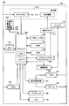
- the terminal 100 includes a short-range wireless communication unit 220 corresponding to a function (sensor) that enables short-range wireless communication, a processor 230, a display driver 214, a flash memory 250, a RAM (Random Access Memory) 252, graphic memory 254, ROM (Read Only Memory) 256, communication circuit 260, signal processing circuit 270, vibrator 280, and memory driver for accessing the installed memory card 152 under the control of the processor 230 151.
- the processor 230 includes a CPU (Central Processing Unit) and a timer for timing.
- the near field communication unit 220 includes radio units 22A and 22B having a near field communication function based on NFC (near field communication).
- Each of the radio units 22A and 22B includes a communication module including a modulation / demodulation unit according to the NFC communication protocol and a communication antenna.
- Short-range wireless communication includes communication using infrared rays or radio waves.
- the display unit 210 constitutes a part of a display-integrated input device that integrally includes the touch panel 140 and the display device 212.
- the display device 212 of the display unit 210 corresponds to an LCD (Liquid Crystal Display) panel, and a touch panel 140 is placed on the display surface.
- the image displayed on the display surface is a visible image that is visible via the touch panel 140. That is, the user can visually recognize the display image on the LCD panel from the outside through the touch panel 140 made of a transparent member.
- the touch panel 140 can employ a resistance film method, a capacitance method, an optical sensor method, or the like.
- the touch panel 140 using the capacitance method will be described.
- the display panel constituting the display surface of the display unit 210 is not limited to the above-mentioned LCD, and an organic EL display (organic electroluminescence display), FED (Field Emission Display), or the like may be used.
- organic EL display organic electroluminescence display
- FED Field Emission Display
- the touch panel 140 is touched on the surface by a human body part such as a finger or an operation body such as a dedicated pen (not shown).
- a human body part such as a finger
- an operation body such as a dedicated pen
- the touch panel 140 outputs an electrical signal corresponding to a position operated by the operating body (hereinafter referred to as an operation position) to the processor 230.
- the touch panel 140 includes a transparent glass plate and a film of a resin material that covers the entire surface of the glass plate, and both are arranged so as to sandwich a transparent electrode grid.
- the electrode grid represents a two-dimensional array surface in which a plurality of electrodes are arranged in a grid pattern.
- the electrode grid has a size that matches the size of the display area of the LCD panel.
- the processor 230 detects an operation (pressing) position on the electrode grid as a two-dimensional coordinate value (X0, Y0) based on the electrical signal from the touch panel 140. Also, by comparing the level of the electrical signal with a predetermined level, it is detected from the comparison result whether the finger has started touching (touching down) on the touch panel 140, and whether the touch has been completed (touching up). To do.
- the touch panel 140 constitutes a part of an operation receiving unit 240 described later for receiving an input by a user operation.
- the LCD panel is configured by two-dimensionally arranging a plurality of electrode elements. Therefore, each electrode element can be specified by the two-dimensional coordinate value (x1, y1).
- the graphic memory 254 stores image data displayed on the display unit 210 by the processor 230.
- the image data represents two-dimensional bitmap data having a size that matches the size of the display area of the LCD panel.
- the display driver 214 generates an electric signal based on each bit value of the image data, and the generated electric signal is an electrode element having a coordinate value (x1, y1) corresponding to the coordinate value (x0, y0) of the bit of the LCD panel. Apply to.
- an image according to the image data in the graphic memory 254 is displayed on the display device 212.
- the processor 230 controls the operation of the terminal 100.
- the processor 230 cooperates with the touch panel 140 to detect a coordinate position indicating the operation position on the touch panel 140, more specifically, coordinate data.
- the operation accepting unit 240 of the processor 230 detects an electrode position corresponding to the operation position on the electrode grid based on the electric signal from the touch panel 140, and uses the conversion coefficient in which the detected electrode position is determined in advance.
- the coordinate data is acquired by converting the coordinate values of the corresponding points on the touch panel 140.
- the operation reception unit 240 is based on time-series coordinate data based on electric signals input in time series, and a touch move locus from the start point (touch down) to the end point (immediate touch up) of the operation on the touch panel 140.
- Has a trajectory detection unit that detects a trajectory composed of a series of coordinate values.
- the series of coordinate values are time-series coordinate values according to the detection order. Note that the method of acquiring the coordinate value from the electrode position corresponding to the operation position is not limited to the method using the conversion coefficient, and the corresponding coordinate value may be read from the table by searching the table.
- the operation receiving unit 240 calculates the coordinate position of the center of gravity of the touch area and touches it.
- the detected operation position is detected.
- the flash memory 250 holds data given to the terminal 100 or data generated by the processor 230 in a nonvolatile manner.
- the RAM 252 temporarily holds data generated by the processor 230.
- the graphic memory 254 stores data for displaying an image on the display device 212.
- the RAM 252 and the graphic memory 254 may be configured as a single unit.
- the ROM 256 holds firmware for operating the terminal 100, the above-described program for accepting operation input and other various programs, and data preliminarily input as setting values for causing the terminal 100 to perform operations specific to the ROM 256. Yes.
- the display driver 214 performs a drawing operation based on the data stored in the graphic memory 254 on the display device 212.
- the display device 212 displays an image according to the operation.
- the communication circuit 260 converts the signal received by the antenna 120 and sends the converted signal to the processor 230. In another aspect, communication circuit 260 converts the signal sent from processor 230 into a signal for transmission, and sends the converted signal to antenna 120. In the present embodiment, the communication circuit 260 has a function of performing communication according to a communication protocol different from NFC communication. For example, communication is performed according to a protocol that enables wireless communication over a relatively long distance using a high-frequency signal such as a telephone call.
- the signal processing circuit 270 converts the electrical signal sent from the microphone 160 and sends the converted signal to the processor 230.
- signal processing circuit 270 converts the signal sent from processor 230 into a signal for audio output, and sends the converted signal to speaker 130.
- the speaker 130 outputs sound based on the signal.
- Vibrator 280 oscillates with a vibration pattern defined in advance based on a signal sent from processor 230.
- the operation received by the processor 230 is not limited to a user operation via the touch panel 140, and includes an operation such as pressing a physical button such as the power button 150.
- FIG. 4 is a conceptual diagram of the information input device according to the present embodiment.
- the information input device includes a display unit 210 including a touch panel 140 and a display device 212, and an operation receiving unit 240.
- a graphic memory 254 and a display driver 214 are shown in connection with the information input device.
- the graphic memory 254 stores data such as an execution result of the program or an image to be displayed by the processor 230 and data generated by the display control unit 290 based on information from the operation reception unit 240.
- the display driver 214 drives the LCD panel of the display device 212 based on the data in the graphic memory 254, so that the display unit 210 displays an image (stroke trajectory or the like) by a user operation superimposed on the image.
- the display surface of the LCD panel of the display device 212 and the entire surface (operation surface) of the touch panel 140 placed thereon have the same shape and area, but at least the surface on which the touch panel 140 can be operated. It suffices if the display area fits inside. As described above, the area that can accept the operation input of the touch panel 140 corresponds to the display area of the LCD panel, and here, the entire surface of the LCD panel is the display area.
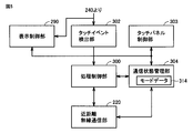
- FIG. 5 is a diagram showing a functional configuration according to the embodiment of the present invention in association with the configuration of FIG. Referring to FIG. 5, each function is realized by a program executed by CPU of processor 230 or a combination of a program and a circuit. The program is stored in advance in a memory such as the ROM 256.
- the CPU of processor 230 has a touch event detection unit 302 for detecting a touch operation on touch panel 140 as an event from an output of operation reception unit 240, a touch panel control unit 303 for controlling touch panel 140, A processing control unit 300 corresponding to a CPU and a communication state management unit 304 for managing the state (communication mode) of short-range wireless communication of the terminal 100 are provided.
- the communication state management unit 304 manages the communication mode of the terminal 100 using the data 314 indicating the communication mode.
- Mode data 314 is stored in a predetermined area of RAM 252.
- the communication state management unit 304 sets either “communication mode” or “non-communication mode” in the mode data 314 based on the output of the processing control unit 300.
- the “communication mode” mode data 314 indicates either “transmission mode” or “reception mode”.
- the terminal 100 detects near field communication when it first receives a signal of a predetermined frequency according to NFC.
- the short-range wireless communication is detected to recognize the address of the counterpart terminal 100, and the operation mode shifts to the communication mode.
- a terminal 100 that has activated a P2P (Peer to Peer) communication function as an NFC function always transmits a carrier wave from the short-range wireless communication unit 220 in order to detect a partner terminal during P2P activation. Therefore, when the terminals 100 that are activated by P2P approach each other at a short distance, the processing control unit 300 between the terminals 100 detects the reception of the carrier wave from the output of the short-range wireless communication unit 220, and the communication state management unit The detection result is output to 304.
- P2P Peer to Peer
- the communication state management unit 304 changes the mode data 314 to indicate “communication mode” from the detection result. This is called “a state in which near field communication is recognized”. On the other hand, when the carrier wave is not detected or the end of communication is detected, the mode data 314 is changed to indicate “non-communication mode”.
- the output of the short-range wireless communication unit 220 includes an identifier for identifying one of the wireless units 22A and 22B that has received the carrier wave. Therefore, the process control unit 300 can determine which of the radio units 22A and 22B is receiving the carrier wave. When it is determined that the wireless unit 22A is receiving, it is determined that the carrier wave is detected on the surface of the touch panel 140, and when it is determined that the wireless unit 22B is receiving, the carrier wave is detected on the back surface of the housing 110. It is determined that
- the transmission object that is touched first is the transmission side, and the other is the reception side.
- the terminal 100 when the user intends to transmit an object (data such as an image), the user touches an icon of a transmittable object (transmission candidate) displayed on the touch panel 140.
- the touch event detection unit 302 detects the touch event, and outputs an event detection notification including the touch operation position to the processing control unit 300.
- the process control unit 300 determines that the transmission object is designated from the event detection notification, and outputs the determination result to the communication state management unit 304.
- the communication state management unit 304 sets (changes) the mode data 314 to “transmission mode” based on the determination result.
- the process control unit 300 identifies a transmission object designated by the user from the event detection notification, reads the identified object from the RAM 252, and outputs it to the short-range wireless communication unit 220.
- the short-range wireless communication unit 220 determines the type of the current communication mode from the mode data 314. When it is determined that the mode is “transmission mode”, transmission of the object is started.
- the processing control unit 300 Prior to the start of object transmission, the processing control unit 300 notifies the counterpart terminal 100 via the short-range wireless communication unit 220. In the counterpart terminal 100, when receiving the notification, the processing control unit 300 changes the mode data 314 to indicate “reception mode”.
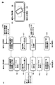
- FIG. 6 is a diagram for explaining processing according to the embodiment of the present invention. Here, it is assumed that short-range wireless communication is performed between two terminals A and B (both are terminals 100).
- FIG. 6B schematically shows a state in which the receiving side terminal A is brought close to the transmitting side terminal B in association with the processing flowchart of FIG.
- FIG. 7 shows a flowchart of invalidation processing according to the present embodiment.
- FIG. 8 shows a flowchart of the activation process according to the present embodiment.
- processing control unit 300 determines whether or not the carrier wave signal by short-range wireless communication is detected from the output of short-range wireless communication unit 220 on the surface of the housing, that is, on the surface of touch panel 140. Determination is made (step R19). If it is determined that it is not on the surface of touch panel 140 (NO in step R19), the process ends and returns to the original process. On the other hand, if it determines with having detected on the surface of the touch panel 140 (it is YES at step R19), the touch panel 140 will be invalidated (step R21), a process will be complete
- touch panel invalidation means that an electrical signal (capacitance change signal) generated when the touch panel 140 is operated by the operating body is output from the touch panel 140, but the processing control unit 300 inputs this. This indicates that the operation receiving unit 240 is controlled not to be performed (ignored).
- the “touch panel invalidation” is not limited to a method realized by software processing that ignores the signal from the touch panel 140, and may be realized by hardware processing that does not supply power to the touch panel 140, or a combination thereof. May be realized.
- the processing control unit 300 may be in a state where no instruction is given to the terminal 100. it can.
- the process control unit 300 repeatedly executes the enabling process of FIG. 8 when the flag of the internal register indicates “invalid”.
- the process control unit 300 measures an elapsed time after the flag is set to “invalid” using a timer, and compares the measured time with a predetermined time. Based on the comparison result, it is determined whether or not a predetermined time length has elapsed since the flag was set to “invalid” (step R27). If it is determined that the time has elapsed (YES in step R27), the process proceeds to step R31. If it is determined that the time has not elapsed (NO in step R27), it is determined whether or not the short-range wireless communication is completed. Determination is made (step R29).
- step R29 If it is determined that the carrier wave signal is received and communication is continued (NO in step R29), the process returns to step R27, but if it is determined that communication is completed (YES in step R27), the process is performed.
- the control unit 300 changes the value of the flag to indicate “valid” and switches the touch panel 140 from the invalid state to the valid state based on the change of the flag value to “valid” (step R31).
- the process control unit 300 causes the operation reception unit 240 to resume the operation content reception of the touch panel 140 from the invalidation state by the interrupt process. Transition. Thereafter, the input of instructions based on the operation content of the touch panel 140 by the operating body is resumed.
- the predetermined time is determined based on a standard time length required from the start to the completion of the short-range wireless communication, and is fixed to, for example, a few seconds. Further, the predetermined time may be variable. For example, the processing control unit 300 measures and varies the length of time to make the invalidation state based on the conditions of the short-range wireless communication path (such as the SN ratio of the communication path) or the amount of data to be transmitted (or data type). (The time required for communication increases when there is a lot of noise, or the time required increases if there is a large amount of data.)
- the touch panel 140 is changed. Since the state is switched from the invalid state to the valid state, the “touch panel invalidation” state can be prevented from continuing for a long period of time, and the operability can be maintained.
- step R27 since the condition (step R27) in which a predetermined time elapses is determined first among the above two conditions, an error occurs in short-range wireless communication, and retransmission is repeated. In addition, it is possible to prevent the “touch panel invalidation” state from continuing for a long period of time and maintain operability.
- the touch panel invalidation process (FIG. 7) is executed in the terminal A on the transmission side (step R5).
- the process control unit 300 displays the icon of the transmittable object on the display unit 210A via the display control unit 290 based on the mode data 314 indicating “communication mode” (step R7).
- an icon of a transmittable object is displayed on the display unit 210B (step S7).
- the receiving terminal A even if the operating tool accidentally touches the touch panel 140 of the terminal A (operation OP2) in a state where the touch panel is invalidated, the receiving terminal A does not operate due to the erroneous operation of the terminal A. Distance wireless communication continues. Even if the icon of the transmission object is touched by mistake (operation OP2), the object is not transmitted from the terminal A.
- an icon of an object to be transmitted is displayed, and the user touches the icon (operation OP3). By this touch operation, transmission of the designated object is started (steps S9 and R9).
- the process control unit 300 of the terminal A detects the end of communication of the object from the signal received from the terminal B, it executes the touch panel validation process (step R11).
- the processing control unit 300 displays a predetermined image representing the completion of the transmission / reception instead of the icon of the transmission object.
- the terminal A on the receiving side is a case where short-distance wireless communication is performed with the terminal B by the radio unit 22A on the front surface side of the touch panel 140, that is, the radio unit 22A on the side receiving operation by the operating tool.
- the touch panel 140 is invalidated.
- the short-distance wireless communication is performed by the wireless unit 22B on the back side of the housing, that is, the wireless unit 22A on the housing surface side (front surface of the touch panel 140) does not perform short-range wireless communication. Accordingly, the “touch panel invalidation” routine is not started on the terminal B, and the operation receiving unit 240 remains in a state where it can accept the operation content from the touch panel 140. Therefore, the user can display the display image on the touch panel 140 of the terminal B. It is possible to operate and input instructions while referring to them.
- the user can perform communication processing while viewing the screen.
- the entire surface area of the touch panel 140 is invalidated, but the invalidation may be limited to a partial area as in the present embodiment.
- FIG. 9 is a diagram showing an example of an approach mode between terminals according to Embodiment 2 of the present invention.
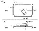
- touch panel 140 of receiving terminal A includes area E1 to be invalidated at the time of “touch panel invalidation”, and short-range wireless signals are detected in radio area 22A within the area E1 ( Area E2 that can be transmitted and received).
- Area E2 Area E2 that can be transmitted and received.
- the touch panel operation can be accepted in other areas except for the partial area that is set to “touch panel invalidation”.
- FIG. 9 schematically shows a state in which the area E2 from which the radio unit of the terminal B can detect the carrier wave signal is viewed from above, and the position and size of the area E2 are arranged with the communication module of the radio unit 22A. This corresponds to the position and size of the area.
- the areas E1 and E2 have a rectangular shape here for the sake of simplicity, but the shape is not limited to this.
- designated area information indicating the position and size of the area E2 on the touch panel 140 is stored in advance in a nonvolatile area of the RAM 252 or the like.
- the designated area information is indicated by the coordinate value of the touch panel 140.
- FIG. 10 is a flowchart of invalidation processing according to the first method of the second embodiment of the present invention.
- the determination process in step R19 is executed as in the first embodiment. If it is determined that the surface is not on the housing surface, that is, the front surface side of the touch panel 140 (NO in step R19), the process ends and returns to the original process. On the other hand, if it is determined that the touch panel 140 has been detected on the surface (YES in step R19), that is, if a short-range wireless communication signal is detected in area E2, "touch panel invalidation" processing is executed.
- the process control unit 300 reads the designated area information of the area E2 from the RAM 252 (step R41).
- the area E1 of the touch panel 140 is invalidated (step R43). Specifically, the position and size of the area E1 are obtained by calculating from the designated area information of the area E2 according to a predetermined arithmetic expression.
- the processing control unit 300 controls the operation receiving unit 240 so that the operation indicating the coordinate value in the rectangular area indicated by the designated area information of the area E1 is ignored (discarded) among the operation contents of the touch panel 140. Therefore, other inputs are accepted, and the process control unit 300 performs processing according to the accepted operation content. Thereby, the touch panel invalidation according to the first method is realized. Thereafter, the process is terminated and the process returns to the original process.
- the processing control unit 300 changes the flag indicating whether the touch panel 140 is valid / invalid stored in an internal register (not shown) to indicate “invalid”.
- the process control unit 300 continues to ignore the operation input from the area E1 as described above while the flag indicates “invalid”, but the flag is changed from “invalid” to “valid” by the process of FIG.
- the operation reception unit 240 is controlled to cancel the invalidation of the operation content in the area E1.
- the operation accepting unit 240 resumes accepting operation input from the entire surface of the touch panel 140 including the area E1.
- the size and position of the invalidation area E1 are fixed, but may be variable.
- the process control unit 300 has a function of a region changing unit that changes at least one of the size of the region E1 and the position on the touch panel 140. At least one of the position and size of the area E1 is variably set by the area changing unit.
- the terminal 100 incorporates a proximity sensor (not shown) on the surface side of the touch panel 140.
- the mounted proximity sensor has detection electrodes arranged in an array corresponding to the surface of the touch panel 140.
- the detection body conductor such as the operation body or the terminal 100
- the corresponding detection electrode outputs a capacitance signal corresponding to the distance from the detection body.
- the region changing unit of the processing control unit 300 detects the presence / absence of the approach and the position / size of the approached area based on the output from the proximity sensor (the position of the electrode and the amount of change in its capacitance). Based on the above, the designated area information regarding the area E1 is acquired.
- a capacitance type proximity sensor function using the touch panel 140 can be used instead of specially mounting the proximity sensor. That is, the operation reception unit 240 detects that the detection body has approached the touch panel surface from the input by the floating touch operation of the touch panel 140.
- the “floating touch operation” indicates an operation in which an instruction can be input by the operating body from a change in capacitance by bringing a finger close to the surface of the touch panel 140 (without actually touching the screen). .
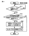
- FIG. 11 is a flowchart of invalidation processing according to the second method of the second embodiment of the present invention.
- the processing control unit 300 determines whether or not the detection body is approaching the surface of the touch panel 140 from the output of the proximity sensor (step R17). Specifically, the amount of change in capacitance output from the proximity sensor is compared with a predetermined value, and the presence or absence of approach is determined from the comparison result.
- step R17 If it is not determined that the vehicle is approaching (NO in step R17), the process in step R17 is repeated. If it is determined that the vehicle is approaching (YES in step R17), the determination in step R19 is performed as in the first embodiment. Processing is executed. If it is determined that it is not on the surface of touch panel 140 (NO in step R19), the process ends and returns to the original process. On the other hand, if it is determined that the touch panel 140 has been detected on the surface (YES in step R19), a “touch panel invalidation” process is executed.
- the process control unit 300 acquires the position where the detection body is approaching from the output of the proximity sensor (step R45). Then, the designated area information of the area E1 is calculated from the acquired position according to a predetermined arithmetic expression.
- the process control unit 300 controls the operation accepting unit 240 so as to invalidate the area E1 of the touch panel 140 indicated by the acquired designated area information (step R47). When invalidated, the operation accepting unit 240 ignores the operation content indicating the coordinate value in the rectangular area indicated by the designated area information of the area E1 among the operation content from the touch panel 140, and accepts the rest. Thereby, the touch panel invalidation according to the second method is realized. Thereafter, the process ends and returns to the original process.
- the process control unit 300 changes the flag indicating whether it is valid / invalid to indicate “invalid”. As described above, the operation input from the area E1 is ignored while the flag indicates “invalid”. However, when the flag is changed from “invalid” to “valid” by the processing of FIG. Is released, and the operation receiving unit 240 resumes receiving operation inputs from the entire surface of the touch panel 140 including the area E1.
- the touch panel 140 of the terminal A on the receiving side when the area size that can be input to the touch panel 140 of the terminal A on the receiving side is very large, short-distance wireless communication is performed on a part of the touch panel 140 (area E2).
- the touch panel is invalidated in the peripheral part (area E1) of the area E2, but the touch panel is not invalidated in other parts except for the touch panel operation.
- the terminal 100 may be equipped with both invalidation functions according to the first and second embodiments and selectively activate one of them according to a user operation. Further, the processing control unit 300 may select the one to be activated from the type of object (image (still image, moving image) data, audio data, personal information, etc.) transmitted during the short-range wireless communication. Further, the process control unit 300 may activate the one selected from the types of application programs activated during the short-range wireless communication. Furthermore, in short-range wireless communication, the terminal 100 may transmit / receive terminal model information and select the one to be activated from the terminal model. Further, the selection of the first and second methods of the second embodiment can also be selected based on the same criteria.
- Such a program is a memory medium attached to the terminal 100, and can be non-temporarily recorded on a recording medium readable by the CPU and provided to the terminal 100 as a program product.
- the memory medium includes a card-shaped memory card 152 that is detachably attached to the terminal 100, a CD (Compact Disc) -ROM, a ROM, a RAM, and the like.
- the CPU reads out the program from the attached memory medium via the memory driver and stores it in the RAM 252 or the like.
- the program stores the program received by the antenna 120 via the network and received by the CPU in a predetermined storage area of the RAM 252. By these methods, a program may be appropriately provided from the outside.
- the provided program product includes the program itself and a recording medium in which the program is recorded non-temporarily.
- the wireless units 22A and 22B for short-range wireless communication are provided on both the front surface and the back surface of the housing, but a configuration including one may be used. Specifically, the terminal 100 on the receiving side only needs to be able to communicate on the front surface side of the touch panel 140, and thus the wireless unit 22B may not be provided on the rear surface side of the housing.
- short-range wireless communication on both the front and back sides of the housing may be controlled using a single wireless unit.
- an antenna laid on the front surface side of the touch panel 140 and an antenna laid on the back side of the housing 110 may be connected to one communication module, and the communication module may transmit and receive signals from both antennas.
- the transmitting terminal need not have the same configuration as the receiving terminal 100.
- the terminal on the transmission side may be a short-distance wireless communication card used for electronic money transactions or the like. That is, it is also possible to apply payment using electronic money to a case where a customer holds his / her card over the touch panel of a payment terminal and communicates.
- FIG. 12 is a diagram illustrating a communication mode of terminal 100 according to the embodiment of the present invention.
- the user performs short-distance wireless communication by bringing the wireless unit 22B of the terminal 100B held by the user closer to the area E2 of the touch panel 140 of the terminal 100A.
- FIG. 13 shows a case where communication is performed without hindrance in the communication mode of FIG. 12A
- FIG. 14 shows a case where communication hinders.
- FIG. 13 when the phone book data is transmitted from the terminal B to the terminal A (see (A) in FIG. 13), the phone book data is displayed on the terminal B as an object to be transmitted, and the photo is displayed on the terminal A. Although the data is displayed (see FIG. 13B), the two terminals are not yet in the “recognized short-range wireless communication” state (see FIG. 13A).
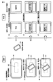
- FIG. 14 when short-range wireless communication is started in the mode of FIG. 12A, the process proceeds in the same manner as in FIGS. 13A to 13D (FIG. 14A).
- D To (D)), and shows a case where the user's hand holding the terminal 100B is in contact with the surface of the touch panel 140 of the terminal A (see the contact portion TA) as shown in FIG. 12B (see FIG. 14).
- E See (E)).
- the processing control unit 300 of the terminal A transmits photo data being displayed on the terminal A to the terminal B by the wireless unit 22A based on an erroneous (unintentional) touch operation input of the contact unit TA of the touch panel 140.
- FIG. 14F Therefore, in the case of FIG. 14, an erroneous operation of the contact portion TA causes a problem that unintended photo data of the terminal A is transmitted instead of the phone book data of the terminal B to be originally transmitted.
- the trouble can be reliably prevented. That is, at the time of short-range wireless communication, the terminal A on the receiving side is “touch panel invalidated”, so that even if the contact portion TA is generated, the operation input is not accepted.
- NFC is a short-range wireless communication similar to FeliCa (registered trademark), and the communication distance is several centimeters.
- the malfunction can be prevented by disabling the touch panel. Therefore, it is possible to realize the convenience of the operation that data can be transferred to another terminal only by the operation of the touch panel 140 and the accuracy of data management that can prevent erroneous data transmission due to an erroneous operation.
- 22A, 22B wireless unit 100 terminal, 140 touch panel, 220 short-range wireless communication unit, 230 processor, 240 operation reception unit, 290 display control unit, 300 processing control unit, 302 touch event detection unit, 303 touch panel control unit, 304 communication Status management part, 314 mode data, E1, E2 area, TA contact part.
Landscapes
- Engineering & Computer Science (AREA)
- Theoretical Computer Science (AREA)
- General Engineering & Computer Science (AREA)
- Human Computer Interaction (AREA)
- Computer Hardware Design (AREA)
- Physics & Mathematics (AREA)
- General Physics & Mathematics (AREA)
- Computer Networks & Wireless Communication (AREA)
- Signal Processing (AREA)
- Telephone Function (AREA)
- User Interface Of Digital Computer (AREA)
- Position Input By Displaying (AREA)
Abstract
端末装置は、タッチパネル(140)における操作を受付けるための操作受付部(240)と、外部装置と無線通信するための通信部(220)と、外部装置が接近している場合に当該外部装置と無線通信するとき、タッチパネルにおける少なくも一部領域における操作内容を受付けないように操作受付部を制御する制御部(300)と、を備える。
Description
この発明は、端末装置に関し、特に、無線通信機能を備える端末装置に関する。
従来、NFC(near field communication)による近距離無線通信機能がスマートフォン等の携帯端末に搭載されることで、近接した端末へのデータ転送が可能になる。この場合に、ユーザはタッチパネルのタッチ操作によりデータ送受信を開始させる。したがって、タッチパネルの誤操作がされると、意図しない相手端末にデータが送信される恐れがある。
このような課題を解決するために、特許文献1(特開2009-171234号公報)では、送信側および受信側の両方の端末をユーザがタッチして、両方の指紋が一致すれば、正しいデータと判断して送信する仕組みが提案されている。
しかしながら、特許文献1では、送受信する両端末を操作する指紋の一致に基づく判定であるから、指紋設定に手間がかかる。
それゆえに本発明の目的は、簡単かつ確実に外部装置と通信することができる端末装置を提供することである。
この発明のある局面に従う端末装置は、タッチパネルにおける操作を受付けるための操作受付部と、外部装置と無線通信するための通信部と、外部装置が接近している場合に当該外部装置と無線通信するとき、タッチパネルにおける少なくも一部領域における操作内容を受付けないように操作受付部を制御する制御部と、を備える。
本発明によれば、外部装置が接近している場合に当該外部装置と無線通信するとき、タッチパネルにおける少なくも一部領域における操作内容を受付けないように操作受付部を制御する。
このような簡単構成で、誤操作による無線通信時の支障を防止して、外部装置と通信することができる。
以下、本発明の各実施の形態について図面を参照し詳細に説明する。なお、同一の構成要素には各図において同一の符号を付し、詳細な説明は繰返さない。
本実施の形態では、携帯型端末装置を例示するが携帯型端末に限定されず、据え置き型の端末装置であってもよい。携帯端末装置は、例えば、携帯電話、スマートフォン、PDA(Personal Digital Assistant)、タブレット端末などを含む。
[実施の形態1]
<ハードウェア構成>
図1、図2および図3を参照して、本実施の形態に係る携帯端末装置(以下、単に端末という)100の構成について説明する。図1と図2は、端末100の外観を表わす図である。図3は端末100のハードウェア構成を表わすブロック図である。図1を参照して、端末100は、筐体110、アンテナ120、スピーカ130、周知の抵抗膜方式のタッチパネル140と表示装置212を有する表示部210、電源ボタン150、マイク160およびLED(Light Emitting Diode)170を備える。端末100には、カード状の記録媒体であるメモリカード152が外部から着脱自在に装着される。
<ハードウェア構成>
図1、図2および図3を参照して、本実施の形態に係る携帯端末装置(以下、単に端末という)100の構成について説明する。図1と図2は、端末100の外観を表わす図である。図3は端末100のハードウェア構成を表わすブロック図である。図1を参照して、端末100は、筐体110、アンテナ120、スピーカ130、周知の抵抗膜方式のタッチパネル140と表示装置212を有する表示部210、電源ボタン150、マイク160およびLED(Light Emitting Diode)170を備える。端末100には、カード状の記録媒体であるメモリカード152が外部から着脱自在に装着される。
図2を参照して、筐体110のタッチパネルの表面が配置された側(以下、筐体表面ともいう)には、後述する無線部22Aが内蔵され、また筐体表面とは反対側の面(以下、筐体裏面ともいう)には、後述する無線部22Bが内蔵される。
端末100は、図1に示される構成に加えて、近距離無線通信を可能にする機能(センサ)に相当する近距離無線通信部220、プロセッサ230、表示ドライバ214、フラッシュメモリ250、RAM(Random Access Memory)252、グラフィックメモリ254、ROM(Read Only Memory)256、通信回路260、信号処理回路270、バイブレータ280および装着されたメモリカード152をプロセッサ230の制御のもとにアクセスするためのメモリドライバ151を備える。プロセッサ230はCPU(Central Processing Unit)および計時のためのタイマなどを含む。
近距離無線通信部220は、NFC(near field communication)による近距離無線通信機能を有する無線部22Aと22Bを含む。無線部22Aと22Bは、いずれもNFC通信プロトコルに従う変調・復調部を含む通信モジュールと通信アンテナとを有する。近距離無線通信は、赤外線または電波による通信を含む。
表示部210は、タッチパネル140と表示装置212とを一体的に含む表示一体型入力装置の一部を構成する。表示部210の表示装置212はLCD(Liquid Crystal Display)パネルに相当し、その表示面上にはタッチパネル140が載置される。表示面において表示される画像はタッチパネル140を介して視認可能な可視画像である。つまり、ユーザはLCDパネルによる表示画像を透明部材からなるタッチパネル140を介して外部から視認することができる。ここでは、タッチパネル140は抵抗膜方式、静電容量方式、光センサ方式などを採用できるが、ここでは、静電容量方式を用いたタッチパネル140を説明する。
表示部210の表示面を構成する表示パネルには上記のLCDに限定されず、有機ELディスプレイ(organic electroluminescence display)、FED(Field Emission Display:電界放出型ディスプレイ)などを用いてもよい。
タッチパネル140は、表面上を指等の人体部分または専用のペン(図示せず)などの操作体によりタッチなどの操作がされる。ここでは、説明を簡単にするために操作体を指等の人体部分と想定する。タッチパネル140は、操作体により操作された位置(以下、操作位置という)に応じた電気信号をプロセッサ230に出力する。
具体的には、タッチパネル140は、透明のガラス板および当該ガラス板の全面を覆う樹脂材料のフィルムを含み、両者は透明な電極格子を挟むようにして配置される。電極格子は、複数の電極が格子状に配列された2次元配列面を表す。電極格子はLCDパネルの表示領域のサイズに整合したサイズを有する。ユーザは、指でタッチパネル140上のフィルムの点をタッチ(押圧操作)などすると、対応電極から出力される静電容量信号が変化する。
プロセッサ230は、タッチパネル140からの電気信号に基づき、電極格子における操作(押圧)位置を2次元座標値(X0,Y0)として検出する。また、電気信号のレベルと所定のレベルとを比較することにより、比較結果から、指がタッチパネル140上にタッチ開始(タッチダウン)したかを検出し、またタッチ終了(タッチアップ)したかを検出する。
このようにタッチパネル140は、ユーザ操作による入力を受け付けるための後述の操作受付部240の一部を構成する。
LCDパネルは、複数の電極素子が2次元配列されて構成される。したがって、各電極素子を2次元座標値(x1,y1)により特定することができる。グラフィックメモリ254には、プロセッサ230により表示部210に表示される画像データが格納される。画像データは、LCDパネルの表示領域のサイズに整合するサイズを有した2次元配列のビットマップデータを表す。表示ドライバ214は当該画像データの各ビット値に基づく電気信号を生成し、生成した電気信号をLCDパネルの当該ビットの座標値(x0、y0)に対応した座標値(x1,y1)の電極素子に印加する。これにより、表示装置212には、グラフィックメモリ254の画像データに従う画像が表示される。
プロセッサ230は端末100の動作を制御する。プロセッサ230はタッチパネル140と協同して、タッチパネル140上の操作位置を示す座標位置、より特定的には座標データを検出する。
具体的には、プロセッサ230の操作受付部240は、タッチパネル140からの電気信号に基づき、電極格子上の操作位置に対応の電極位置を検出し、検出した電極位置を予め定めた変換係数を用いてタッチパネル140上の対応する点の座標値に変換することにより座標データを取得する。また、操作受付部240は、時系列に入力する電気信号に基づく時系列状の座標データに基づき、タッチパネル140における操作の始点(タッチダウン)から終点(直後のタッチアップ)までのタッチムーブの軌跡を表す一連の座標値からなる軌跡を検出する軌跡検出部を有する。一連の座標値は検出順に従う時系列の座標値である。なお、操作位置に対応する電極位置から座標値を取得する方法は、変換係数を用いる方法に限定されず、テーブルを検索してテーブルから対応する座標値を読出すとしてもよい。
なお、操作体のタッチ面積の大きさによっては座標位置として複数の座標値が検出されるが、その場合には、操作受付部240は、タッチ面積の重心の座標位置を算出し、これをタッチされた操作位置として検出する。
フラッシュメモリ250は、端末100に対して与えられたデータあるいはプロセッサ230によって生成されたデータを不揮発的に保持する。
RAM252は、プロセッサ230によって生成されたデータを一時的に保持する。
グラフィックメモリ254は、表示装置212において画像を表示するためのデータを格納する。なお、他の局面において、RAM252とグラフィックメモリ254とが一体として構成されていてもよい。
グラフィックメモリ254は、表示装置212において画像を表示するためのデータを格納する。なお、他の局面において、RAM252とグラフィックメモリ254とが一体として構成されていてもよい。
ROM256は端末100を作動させるためのファームウェア、上述の操作入力受付のためのプログラムその他の各種プログラムと、端末100に固有の動作を実行させるために設定値として予め入力されたデータとを保持している。
表示ドライバ214は、グラフィックメモリ254に格納されているデータに基づく描画動作を表示装置212に対して実行する。表示装置212は、その動作に従って画像を表示する。
通信回路260は、アンテナ120によって受信された信号を変換し、変換後の信号をプロセッサ230に送出する。また他の局面において、通信回路260は、プロセッサ230から送られた信号を送信用の信号に変換し、変換後の信号をアンテナ120に送出する。本実施の形態では、通信回路260は、NFC通信とは異なる通信プロトコルに従って通信する機能を有する。例えば、通話など高周波信号による比較的に長距離の無線通信が可能なプロトコルに従い通信する。
本実施の形態では、端末100の通信機能については、近距離無線通信部220による通信を説明し、通信回路260による通信の詳細は繰返さない。
信号処理回路270は、マイク160から送られる電気信号を変換し変換後の信号をプロセッサ230に送出する。また、端末100が音声を出力する場合には、信号処理回路270は、プロセッサ230から送られた信号を音声出力用の信号に変換し、その変換後の信号をスピーカ130に送出する。スピーカ130は、その信号に基づき音声を出力する。
バイブレータ280は、プロセッサ230から送られる信号に基づいて予め規定された振動パターンで発振する。
なお、プロセッサ230が受付ける操作は、タッチパネル140を介したユーザ操作に限定されず、電源ボタン150などの物理的ボタンを押下するなどの操作も含む。
図4は、本実施の形態に係る情報入力装置の概念図である。図4を参照して、情報入力装置は、タッチパネル140および表示装置212を含む表示部210、および操作受付部240を備える。図3では、情報入力装置に関連して、グラフィックメモリ254および表示ドライバ214が示される。グラフィックメモリ254にはプロセッサ230によってプログラムの実行結果または表示されるべき画像などのデータが格納されるとともに、表示制御部290が操作受付部240からの情報に基づき生成したデータが格納される。したがって、表示ドライバ214はグラフィックメモリ254のデータに基づき表示装置212のLCDパネルを駆動することにより、表示部210では画像に重畳してユーザ操作による画像(ストロークの軌跡など)が表示される。
本実施の形態では、表示装置212のLCDパネルの表示面と、その上に載置されるタッチパネル140の全面(操作面)とは同じ形状および面積としているが、少なくともタッチパネル140の操作可能な面内に表示領域が収まればよい。このように、タッチパネル140の操作入力を受付可能な領域は、LCDパネルの表示領域に対応しており、ここでは、LCDパネルの全面が表示領域である。
<機能構成>
図5は、本発明の実施の形態に係る機能構成を図4の構成と関連付けて示す図である。図5を参照して、各機能は、プロセッサ230のCPUが実行するプログラム、またはプログラムと回路の組合せにより実現される。プログラムは、予めROM256などのメモリに格納されている。
図5は、本発明の実施の形態に係る機能構成を図4の構成と関連付けて示す図である。図5を参照して、各機能は、プロセッサ230のCPUが実行するプログラム、またはプログラムと回路の組合せにより実現される。プログラムは、予めROM256などのメモリに格納されている。
図5を参照して、プロセッサ230のCPUは、操作受付部240の出力からタッチパネル140におけるタッチ操作をイベントとして検出するためのタッチイベント検出部302、タッチパネル140を制御するためのタッチパネル制御部303、CPUに相当する処理制御部300、端末100の近距離無線通信の状態(通信モード)を管理するための通信状態管理部304を備える。
<通信モードとその切替え>
通信状態管理部304は、通信モードを示すデータ314を用いて端末100の通信モードを管理する。モードデータ314は、RAM252の所定領域に格納される。通信状態管理部304は、処理制御部300の出力に基づきモードデータ314に“通信モード”および“非通信モード”のいずれかをセットする。“通信モード”のモードデータ314は、“送信モード”および“受信モード”のいずれかを示す。
通信状態管理部304は、通信モードを示すデータ314を用いて端末100の通信モードを管理する。モードデータ314は、RAM252の所定領域に格納される。通信状態管理部304は、処理制御部300の出力に基づきモードデータ314に“通信モード”および“非通信モード”のいずれかをセットする。“通信モード”のモードデータ314は、“送信モード”および“受信モード”のいずれかを示す。
端末100はNFCに従う所定周波数の信号を初めて受信したときに、近距離無線通信を検知する。近距離無線通信を検知し相手端末100のアドレスを認識し、動作モードは通信モードに移行する。例えば、NFCの機能にP2P(Peer to Peer)通信機能を起動させている端末100は、P2P起動中は常時、相手端末を検知するために近距離無線通信部220から搬送波が送信され続ける。したがって、P2P起動中の端末100どうしが近距離に接近した場合には、端末100どうしの処理制御部300は、近距離無線通信部220の出力から当該搬送波の受信を検知し、通信状態管理部304に検知結果を出力する。通信状態管理部304は、検知結果からモードデータ314を“通信モード”を示すように変更する。これを、“近距離無線通信を認識した状態”という。一方、搬送波が検知されなくなると、または通信終了を検出するとモードデータ314は“非通信モード”を示すように変更される。
本実施の形態1では、近距離無線通信部220の出力には、無線部22Aおよび22Bのうち搬送波を受信した方を識別する識別子が含まれる。したがって、処理制御部300は、無線部22Aおよび22Bのうち、いずれで搬送波を受信しているかを判定することができる。無線部22Aで受信していると判定したときは、タッチパネル140の表面で搬送波を検知したと判定し、無線部22Bで受信していると判定したときは、筐体110の裏面で搬送波を検知したと判定する。
本実施の形態では、上記のように“通信モード”に移行した端末100どうしのうち、送信オブジェクトが先にタッチ操作された方が送信側となり、他方は受信側となる。具体的には、端末100では、ユーザはオブジェクト(画像などのデータ)を送信しようとする場合に、タッチパネル140に表示中の送信可能オブジェクト(送信候補)のアイコンなどをタッチ操作する。タッチイベント検出部302は操作受付部240からタッチ操作位置を入力するとタッチイベントを検出し、処理制御部300にタッチ操作位置を含むイベント検出通知を出力する。処理制御部300は、イベント検出通知から送信オブジェクトが指定されたと判定し、判定結果を通信状態管理部304に出力する。通信状態管理部304は、判定結果に基づきモードデータ314を“送信モード”にセット(変更)する。また、処理制御部300は、イベント検出通知から、ユーザが指定した送信オブジェクトを特定し、特定したオブジェクトをRAM252から読出し、近距離無線通信部220に出力する。近距離無線通信部220は、オブジェクトが与えられると、モードデータ314から現在の通信モードの種類を判定する。“送信モード”であると判定したとき、オブジェクトを送信開始する。
オブジェクトの送信を開始するに先だって、処理制御部300は、近距離無線通信部220を介し相手端末100に通知する。相手端末100では、処理制御部300は、通知を受信したとき、モードデータ314を“受信モード”を示すように変更する。
<処理フロー>
図6は、本発明の実施の形態に係る処理を説明する図である。ここでは、2台の端末AとB(いずれも、端末100である)との間で近距離無線通信する場合を想定する。
図6は、本発明の実施の形態に係る処理を説明する図である。ここでは、2台の端末AとB(いずれも、端末100である)との間で近距離無線通信する場合を想定する。
図6の(A)の処理フローチャートに関連付けて、図6の(B)には、受信側端末Aを送信側端末Bに接近させた態様が模式的に示される。
図7には、本実施の形態に係る無効化処理のフローチャートが示される。図8には、本実施の形態に係る有効化処理のフローチャートが示される。
・無効化処理
本実施の形態に係る端末100では、近距離無線通信時に“タッチパネル無効化”が実行される。
本実施の形態に係る端末100では、近距離無線通信時に“タッチパネル無効化”が実行される。
図7を参照して、処理制御部300は、近距離無線通信部220の出力から、近距離無線通信による搬送波信号を検知したのは、筐体表面、すなわちタッチパネル140の表面上か否かを判定する(ステップR19)。タッチパネル140の表面上ではないと判定すると(ステップR19でNO)、処理は終了し、元の処理に戻る。一方、タッチパネル140の表面上で検知されたと判定されると(ステップR19でYES)、タッチパネル140を無効化し(ステップR21)、処理を終了し、元の処理に戻る。処理制御部300は、タッチパネル140を無効化すると、内部レジスタ(図示せず)に格納されるタッチパネル140の有効/無効の別を示すフラグを“無効”を示すように変更する。なお、フラグの初期値は、“有効”である。
ここで、“タッチパネル無効化”とは、操作体によりタッチパネル140が操作されて発生した電気信号(静電容量の変化信号)はタッチパネル140から出力されるけれども、処理制御部300は、これを入力しない(無視する)ように操作受付部240を制御することを示す。
なお、“タッチパネル無効化”は、タッチパネル140からの信号を無視するソフトウェア処理により実現する方法に限定されず、タッチパネル140に電源を供給しないハードウェア処理により実現してもよく、または、これら組合わせて実現してもよい。
このように、処理制御部300はフラグが“無効“を示すと判定する時は、操作体によりタッチパネル140が操作されたとしても、端末100に対し何らの指示も与えられない状態とすることができる。
・有効化処理
本実施の形態に係る端末100では、処理制御部300は内部レジスタのフラグが“無効”を示すとき、図8の有効化処理を繰り返し実行する。
本実施の形態に係る端末100では、処理制御部300は内部レジスタのフラグが“無効”を示すとき、図8の有効化処理を繰り返し実行する。
図8を参照して、処理制御部300は、フラグが“無効化”に設定されてからの経過時間をタイマを用いて計時し、計時時間と予め定めた時間を比較する。比較結果に基づき、フラグが“無効”に設定されてから予め定めた時間長さが経過したか否かを判定する(ステップR27)。経過したと判定されると(ステップR27でYES)、ステップR31の処理に移行するが、経過していないと判定されると(ステップR27でNO)、近距離無線通信が完了したか否かが判定される(ステップR29)。搬送波信号が受信されており通信は継続していると判定されると(ステップR29でNO)、ステップR27の処理に戻るが、通信は完了したと判定されると(ステップR27でYES)、処理制御部300はフラグの値を“有効”を示すように変更するとともに、フラグの値が“有効”に変化したことに基づき、タッチパネル140を無効状態から有効状態に切替える(ステップR31)。
このように、フラグが“無効”→“有効”に変化したきは、処理制御部300は、割込み処理によって、操作受付部240を、無効化状態からタッチパネル140の操作内容受付けを再開する状態に遷移させる。以降は、操作体によるタッチパネル140の操作内容に基づく指示の入力が再開する。
なお、上記の予め定めた時間は、近距離無線通信の開始から完了までに要する標準的な時間長さに基づき決定されて、例えば2、3秒の固定とされる。また、予め定めた時間は可変であってもよい。例えば、処理制御部300が計測して近距離無線通信路の条件(通信路のSN比など)、または送信すべきデータ量(またはデータの種類)から無効化状態とする時間長さを可変にする(ノイズが多い時は通信所要時間が長くなる、または、データ量が多ければ所要時間長くなる)。
また、図8では、“タッチパネル無効化”が行われてから予め定めた時間が経過すること、または近距離無線通信が完了することの2つ条件のうちの1つが成立すれば、タッチパネル140を無効状態から有効状態に切替えるので、長期にわたって“タッチパネル無効化”状態が継続するのを回避でき、操作性を維持することができる。
また、図8では、上記の2つの条件のうち予め定めた時間が経過する条件(ステップR27)を先に判定することから、近距離無線通信にエラーが生じて再送などを繰り返す場合であっても、長期にわたって“タッチパネル無効化”状態が継続するのを回避でき、操作性を維持することができる。
・全体処理
図6の(A)に戻り、全体処理を説明する。まず、図6の(B)の態様において、ユーザは、端末Bの筐体110の裏面を端末Aのタッチパネル140表面に近付けたとする(操作OP1)。図6の(A)の操作OP1により、ユーザは端末Bの筐体裏面を、端末Aの筐体表面(タッチパネル表面側)に接近させる。これにより、近距離無線通信可能な状態とされる。
図6の(A)に戻り、全体処理を説明する。まず、図6の(B)の態様において、ユーザは、端末Bの筐体110の裏面を端末Aのタッチパネル140表面に近付けたとする(操作OP1)。図6の(A)の操作OP1により、ユーザは端末Bの筐体裏面を、端末Aの筐体表面(タッチパネル表面側)に接近させる。これにより、近距離無線通信可能な状態とされる。
操作OP1により接近した端末AとBが“近距離無線通信を認識した状態”に移行すると、送信側の端末Aではタッチパネル無効化処理(図7)が実行される(ステップR5)。また、端末Aでは、処理制御部300は、モードデータ314が“通信モード”を示すことに基づき、表示制御部290を介して表示部210Aに送信可能オブジェクトのアイコンを表示する(ステップR7)。このとき、送信側端末Bにおいても、同様に、送信可能オブジェクトのアイコン等が表示部210Bに表示される(ステップS7)。
受信側端末Aでは、タッチパネルが無効化されている状態において、操作体が端末Aのタッチパネル140に誤ってタッチ操作(操作OP2)したとしても、端末Aの当該誤操作により動作することはなく、近距離無線通信は継続する。また、誤って送信オブジェクトのアイコンがタッチ操作された(操作OP2)としても、端末Aからオブジェクトが送信されることはない。
送信側端末Bでは、送信すべきオブジェクトのアイコンが表示されており、ユーザがアイコンをタッチ操作する(操作OP3)。このタッチ操作によって、指定されたオブジェクトの送信が開始される(ステップS9とR9)。
その後、端末Aの処理制御部300は、端末Bから受信した信号から、当該オブジェクトの通信終了を検知すると、タッチパネル有効化処理を実行する(ステップR11)。
その後、端末Aと端末Bでは、オブジェクトの送受信が完了したことに応じて、処理制御部300は、送信オブジェクトのアイコンに代替して、送受信完了を表す所定の画像を表示する。
本実施の形態では、受信側の端末Aはタッチパネル140の表面側の無線部22A、すなわち操作体による操作を受付ける側の無線部22Aにより端末Bと近距離無線通信をするケースであり、端末Aのタッチパネル140が無効化される。一方、送信側の端末Bでは、筐体裏面側の無線部22Bで近距離無線通信を行う、すなわち筐体表面側(タッチパネル140の表面)側の無線部22Aは近距離無線通信をしない。したがって、端末Bでは“タッチパネル無効化”のルーチンは起動されず、操作受付部240はタッチパネル140からの操作内容を受付け可能な状態のままであるから、ユーザは端末Bのタッチパネル140の表示画像を参照しながら操作し指示を入力することができる。
また、図6の(B)に示すように、無線部22Aを筐体表面(タッチパネル140の表面)側に組み込むことで、ユーザは画面を見ながら通信処理をすることができる。
[実施の形態2]
実施の形態1では、タッチパネル140の表面領域の全てを無効化したが、本実施の形態のように、無効化は一部領域に限定するとしてもよい。
実施の形態1では、タッチパネル140の表面領域の全てを無効化したが、本実施の形態のように、無効化は一部領域に限定するとしてもよい。
図9は発明の実施の形態2に係る端末どうしの接近態様の一例を示す図である。図9を参照して、受信側の端末Aのタッチパネル140は、“タッチパネル無効化”時に無効化されるべきエリアE1を含み、当該エリアE1内には無線部22Aにより近距離無線信号を検知(送受信)することのできるエリアE2を含む。具体的には、タッチパネル140の表面領域サイズが大きい場合、表面領域の一部で近距離無線通信を行い、他の領域では操作体によるタッチ操作等を受付け可能にする。これにより、“タッチパネル無効化”とされた一部領域を除く他の領域では、タッチパネル操作を受付けることができる。
図9では、当該搬送波信号を端末Bの無線部が検知できるエリアE2を上部から見た状態を模式的に示しており、エリアE2の位置および大きさは、無線部22Aの通信モジュールが配置されたエリアの位置および大きさに相当する。エリアE1およびE2は、ここでは説明を簡単にするために矩形形状を有するが、形状はこれに限定されない。
本実施の形態2では、“タッチパネル無効化”のエリアE1の設定方法として、次の2つの方法あげる。
(第1の方法)
第1の方法では、エリアE1の大きさおよび位置も固定の場合を説明する。つまり、無線部22Aの位置が固定であることからエリアE2の大きさ(矩形の縦・横の長さなど)および位置も固定とし、したがって、エリアE2を内部に囲む無効エリアE1の大きさおよび位置も固定とする。
第1の方法では、エリアE1の大きさおよび位置も固定の場合を説明する。つまり、無線部22Aの位置が固定であることからエリアE2の大きさ(矩形の縦・横の長さなど)および位置も固定とし、したがって、エリアE2を内部に囲む無効エリアE1の大きさおよび位置も固定とする。
第1の方法では、エリアE2のタッチパネル140における位置および大きさを示す指定エリア情報が、予めRAM252の不揮発性領域などに格納される。指定エリア情報は、タッチパネル140の座標値により示される。
図10は、本発明の実施の形態2の第1の方法に係る無効化処理のフローチャートである。図10では、受信側の端末Aでは実施の形態1と同様にステップR19の判定処理が実行される。筐体表面、すなわちタッチパネル140の表面側ではないと判定すると(ステップR19でNO)、処理は終了し、元の処理に戻る。一方、タッチパネル140の表面上で検知されたと判定されると(ステップR19でYES)、すなわちエリアE2において近距離無線通信の信号が検知されると“タッチパネル無効化”の処理が実行される。
具体的には、処理制御部300はRAM252から、エリアE2の指定エリア情報を読出す(ステップR41)。
続いて、タッチパネル140のエリアE1を無効化する(ステップR43)。具体的には、エリアE1の位置および大きさを、エリアE2の指定エリア情報から、予め定めた演算式に従い算出することで取得する。処理制御部300は、タッチパネル140の操作内容のうち、当該エリアE1の指定エリア情報が示す矩形領域内の座標値を示す操作は無視(破棄)するように操作受付部240を制御する。したがって、それ以外の入力は受付けされて処理制御部300は受付けされた操作内容に従う処理を行う。これにより、第1の方法に従うタッチパネル無効化が実現される。その後、処理を終了し元の処理に戻る。
第1の方法でも、処理制御部300は、内部レジスタ(図示せず)に格納されるタッチパネル140の有効/無効の別を示すフラグを“無効”を示すように変更する。処理制御部300は、フラグが“無効”を示す期間は継続して上記のようにエリアE1からの操作入力を無視するが、図8の処理によりフラグが“無効”から“有効”に変更されると、エリアE1の操作内容の無効化を解除するように操作受付部240を制御する。以降は、操作受付部240は、エリアE1を含むタッチパネル140の全面からの操作入力の受付けを再開する。
(第2の方法)
第1の方法では、無効化のエリアE1の大きさおよび位置は固定としたが、可変にしてもよい。第2の方法では、処理制御部300は、領域E1の大きさ、およびタッチパネル140における位置のうちの少なくとも一方を変化させる領域変化部の機能を有する。領域変化部により、エリアE1の位置および大きさの少なくとも一方が可変に設定される。
第1の方法では、無効化のエリアE1の大きさおよび位置は固定としたが、可変にしてもよい。第2の方法では、処理制御部300は、領域E1の大きさ、およびタッチパネル140における位置のうちの少なくとも一方を変化させる領域変化部の機能を有する。領域変化部により、エリアE1の位置および大きさの少なくとも一方が可変に設定される。
端末100は、タッチパネル140の表面側に近接センサ(図示せず)を内蔵する。搭載された近接センサは、タッチパネル140の面に対応してアレイ状に配置された検出電極を有する。検出体(操作体、端末100などの導体)がタッチパネル140の表面に接近した場合に、対応の検出電極は、検出体との間の距離に応じた静電容量の信号を出力する。処理制御部300の領域変化部は、近接センサからの出力(電極の位置およびその静電容量の変化量)に基づき、接近の有無、および接近したエリアの位置・大きさを検出し、検出結果に基づき、エリアE1に関する指定エリア情報を取得する。
なお、近接センサを特別に搭載するのに代替して、タッチパネル140を利用した静電容量型の近接センサ機能を用いることもできる。つまり、操作受付部240は、タッチパネル140のフローティングタッチ操作による入力から、タッチパネル表面上に検出体が近づいたことを検出する。ここで、「フローティングタッチ操作」は、タッチパネル140の表面に指を近づけることで(実際に画面に触れなくても)、静電容量の変化から、操作体による指示入力が可能になる操作を示す。
図11は本発明の実施の形態2の第2の方法に係る無効化処理のフローチャートである。図11では、受信側の端末Aでは、処理制御部300は近接センサの出力から、検出体がタッチパネル140表面上に接近しているか否かを判定する(ステップR17)。具体的には、近接センサから出力される静電容量の変化量と、予め定めた値とを比較し、比較結果から、接近の有無を判定する。
接近していると判定しないときは(ステップR17でNO)、ステップR17の処理が繰り返されるが、接近していると判定すると(ステップR17でYES)、実施の形態1と同様にステップR19の判定処理が実行される。タッチパネル140の表面上ではないと判定すると(ステップR19でNO)、処理は終了し、元の処理に戻る。一方、タッチパネル140の表面上で検知されたと判定されると(ステップR19でYES)、“タッチパネル無効化”の処理が実行される。
まず、処理制御部300は近接センサの出力から、検出体が接近している位置を取得する(ステップR45)。そして、取得した位置からエリアE1の指定エリア情報を予め定めた演算式に従い算出する。処理制御部300は、取得した指定エリア情報が示すタッチパネル140のエリアE1を無効化するように操作受付部240を制御する(ステップR47)。無効化されると、操作受付部240は、タッチパネル140からの操作内容のうち、当該エリアE1の指定エリア情報が示す矩形領域内の座標値を示す操作内容は無視し、それ以外は受付ける。これにより、第2の方法に従うタッチパネル無効化が実現される。その後、処理は終了し元の処理に戻る。
第2の方法でも、処理制御部300は、“タッチパネル無効化”を行うと、有効/無効の別を示すフラグを“無効”を示すように変更する。フラグが“無効”を示す期間は継続して上記のようにエリアE1からの操作入力は無視されるが、図8の処理によりフラグが“無効”から“有効”に変更されると、無効化は解除されて、操作受部240はエリアE1を含むタッチパネル140の全面からの操作入力受付けを再開する。
第1および第2の方法によれば、受信側の端末Aのタッチパネル140の操作入力可能な面積サイズが非常に大きい場合には、タッチパネル140の一部(エリアE2)で近距離無線通信を行いつつ、エリアE2の周辺部(エリアE1)ではタッチパネル無効化されるが、それを除いた他の部分ではタッチパネル無効化はされずタッチパネル操作が可能になる。
なお、端末100は、実施の形態1および2に従う両方の無効化機能を搭載し、ユーザ操作から、選択的に一方を起動するようにしてもよい。また、処理制御部300は、近距離無線通信時に送信するオブジェクトの種類(画像(静止画、動画)データ、音声データ、個人情報など)から起動する方を選択するとしてもよい。また、処理制御部300は、近距離無線通信時に起動されているアプリケーションプログラムの種類から選択された方を起動するとしてもよい。さらには、近距離無線通信において端末100は端末機種情報を送受信し、端末機種から起動する方を選択するとしてもよい。また、実施の形態2の第1および第2の方法の選択についても、同様の基準で選択することができる。
[実施の形態3]
上述した実施の形態に係る処理に係るプログラムは端末100の記憶領域に予め格納されており、プロセッサ230のCPUが当該プログラムを記憶領域から読出し、プログラムの命令を実行することにより処理が実現される。
上述した実施の形態に係る処理に係るプログラムは端末100の記憶領域に予め格納されており、プロセッサ230のCPUが当該プログラムを記憶領域から読出し、プログラムの命令を実行することにより処理が実現される。
このようなプログラムは、端末100に付属するメモリ媒体であって、CPUが読取り可能な記録媒体に非一時的に記録させて、プログラム製品として端末100に提供することもできる。メモリ媒体は、端末100に着脱自在に装着されるカード形状のメモリカード152、CD(Compact Disc)-ROM、ROM、RAMなどを含む。
CPUは、装着されたメモリ媒体からメモリドライバを介してプログラムを読出しRAM252などに格納する。また、プログラムは、ネットワークを介してアンテナ120により受信されてCPUが受信したプログラムをRAM252の所定記憶領域へ格納する。これらの方法によって、外部から適宜プログラムが提供されるとしてもよい。
提供されるプログラム製品は、プログラム自体と、プログラムが非一時的に記録された記録媒体とを含む。
(変形例)
実施の形態では、筐体表面および筐体裏面の両方側に近距離無線通信のための無線部22Aおよび22Bを備えたが、一方を備える構成であってもよい。具体的には、受信側の端末100はタッチパネル140の表面側で通信可能であればよいため、筐体裏面側に無線部22Bを備えなくともよい。
実施の形態では、筐体表面および筐体裏面の両方側に近距離無線通信のための無線部22Aおよび22Bを備えたが、一方を備える構成であってもよい。具体的には、受信側の端末100はタッチパネル140の表面側で通信可能であればよいため、筐体裏面側に無線部22Bを備えなくともよい。
また、独立した2個の無線部22Aおよび22Bを備えたが、1個の無線部を用いて、筐体表面と筐体裏面の両方側の近距離無線通信を制御するとしてもよい。たとえば、1つの通信モジュールに、タッチパネル140の表面側に敷設されたアンテナおよび筐体110の背面側に敷設されたアンテナを接続し、当該通信モジュールは、両アンテナから信号を送受信するとしてもよい。
また、送信側の端末については、受信側の端末100と同じ構成を持つ必要はない。例えば、送信側の端末は電子マネー取引等に利用されている近距離無線通信可能なカードであってもよい。すなわち電子マネーでの決済を顧客が自己のカードを決済端末のタッチパネル上にかざして通信するケースにも適用することができる。
(実施の形態に係る効果)
図12、図13および図14を参照して、実施の形態に係る効果について説明する。図12は、本発明の実施の形態に係る端末100の通信態様を説明する図である。図12の(A)では、ユーザは把持した端末100Bの無線部22Bを、端末100Aのタッチパネル140のエリアE2に接近させて、近距離無線通信している。
図12、図13および図14を参照して、実施の形態に係る効果について説明する。図12は、本発明の実施の形態に係る端末100の通信態様を説明する図である。図12の(A)では、ユーザは把持した端末100Bの無線部22Bを、端末100Aのタッチパネル140のエリアE2に接近させて、近距離無線通信している。
図13は、図12の(A)の通信態様において、支障なく通信が行われるケースを示し、図14は、通信に支障が出るケースを示す。
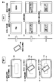
まず、図13のケースを説明する。図13では端末Bから電話帳データを端末Aに送信する場合に(図13の(A)参照)、送信対象のオブジェクトとして、端末Bには電話帳データが表示され、また端末Aには写真データが表示される(図13の(B)参照)が、未だ、両端末では、“近距離無線通信を認識した状態”ではない(図13の(A)参照)。
ここで、ユーザは端末Bを把持して、図12の(A)の態様で近距離無線通信を開始すると、“近距離無線通信を認識した状態”が検出されて(図13の(C)参照)、両端末100の画面には、表示中の送信対象オブジェクトについて“データを送信する場合には画面にタッチしてください”とメッセージが表示される(図13の(D)参照)。
端末Bを把持したユーザが、端末Bの表示メッセージを確認し、表示中の送信対象オブジェクト(電話帳データ)をタッチ操作すると(図13の(E)参照)、端末Bの電話帳データは端末Aに送信され、その後、近距離無線通信は完了し、両端末には通信終了の旨を示すメッセージが表示される(図13の(F)参照)。これにより、近距離無線通信が支障なく行われて、端末Bは端末Aに対して自己の電話帳データを送信し、端末Aは端末Bからの電話帳データを受信することができる。
対して、図14では、図12の(A)の態様で近距離無線通信を開始した場合に、図13の(A)~(D)と同様に処理が進行するとき(図14の(A)~(D)参照)、図12の(B)のように端末100Bを把持したユーザの手が、端末Aのタッチパネル140の表面に接触(接触部TA参照)したケースを示す(図14の(E)参照)。この場合には、端末Aの処理制御部300は、タッチパネル140の接触部TAの誤った(意図しない)タッチ操作入力に基づき、無線部22Aにより端末Aで表示中の写真データを端末Bに送信する(図14の(F)参照)。したがって、図14のケースでは、接触部TAの誤操作により、本来、送信されるべき端末Bの電話帳データではなく、意図しない端末Aの写真データが送信されるという支障が生じる。
上記の実施の形態では、当該支障を確実に防止することができる。すなわち、近距離無線通信時には、受信側の端末Aでは、“タッチパネル無効化”がされることで、接触部TAが生じたとしても、操作入力は受付けされないからである。取り分け、NFCはFeliCa(登録商標)と同様の近距離無線通信であり、通信距離は数cmであるため、通信を行う際に、受信側のタッチパネルに触れることによる誤動作(すなわち、意図しないデータが送信されるなど)が起こりやすいが、本実施の形態によれば、タッチパネル無効化により当該誤動作を防止することできる。したがって、タッチパネル140の操作だけで他の端末にデータを転送できるという操作の簡便性と、誤操作による誤ったデータ送信を防止できるというデータ管理の正確性とを実現することができる。
今回開示された実施の形態はすべての点で例示であって制限的なものではないと考えられるべきである。本発明の範囲は上記した説明ではなくて請求の範囲によって示され、請求の範囲と均等の意味および範囲内でのすべての変更が含まれることが意図される。
22A,22B 無線部、100 端末、140 タッチパネル、220 近距離無線通信部、230 プロセッサ、240 操作受付部、290 表示制御部、300 処理制御部、302 タッチイベント検出部、303 タッチパネル制御部、304 通信状態管理部、314 モードデータ、E1,E2 エリア、TA 接触部。
Claims (5)
- タッチパネル(140)における操作を受付けるための操作受付部(240)と、
外部装置と無線通信するための通信部(220)と、
前記外部装置が接近している場合に当該外部装置と無線通信するとき、前記タッチパネルにおける少なくも一部領域における操作内容を受付けないように前記操作受付部を制御する制御部(300)と、を備える、端末装置。 - 前記制御部は、
前記通信部の無線通信による受信信号から、前記外部装置が接近しているか否かを判定する、請求項1に記載の端末装置。 - 前記制御部は、
前記外部装置と無線通信が完了したとき、前記タッチパネルにおける操作内容の受付けを開始するように前記操作受付部を制御する、請求項1または2に記載の端末装置。 - 前記制御部は、前記一部領域の大きさ、および前記タッチパネルにおける位置のうちの少なくとも一方を変化させる領域変化部を含む、請求項1から3のいずれかに記載の端末装置。
- 前記タッチパネルは、電極を有し、且つ前記電極と導体の接近距離により変化する静電容量信号を出力し、
前記領域変化部は、
前記タッチパネルが出力する前記静電容量信号から、前記一部領域の大きさおよび前記タッチパネルにおける位置の少なくとも一方を変化させる、請求項4に記載の端末装置。
Applications Claiming Priority (2)
| Application Number | Priority Date | Filing Date | Title |
|---|---|---|---|
| JP2013-113029 | 2013-05-29 | ||
| JP2013113029A JP2014232985A (ja) | 2013-05-29 | 2013-05-29 | 端末装置 |
Publications (1)
| Publication Number | Publication Date |
|---|---|
| WO2014192583A1 true WO2014192583A1 (ja) | 2014-12-04 |
Family
ID=51988617
Family Applications (1)
| Application Number | Title | Priority Date | Filing Date |
|---|---|---|---|
| PCT/JP2014/063291 Ceased WO2014192583A1 (ja) | 2013-05-29 | 2014-05-20 | 端末装置 |
Country Status (2)
| Country | Link |
|---|---|
| JP (1) | JP2014232985A (ja) |
| WO (1) | WO2014192583A1 (ja) |
Cited By (1)
| Publication number | Priority date | Publication date | Assignee | Title |
|---|---|---|---|---|
| EP3032395A1 (en) * | 2014-12-12 | 2016-06-15 | Konica Minolta, Inc. | Image processing apparatus, method for controlling the same, and program |
Families Citing this family (4)
| Publication number | Priority date | Publication date | Assignee | Title |
|---|---|---|---|---|
| JP2017033030A (ja) * | 2013-12-20 | 2017-02-09 | パナソニックIpマネジメント株式会社 | 情報処理装置 |
| JP6315141B2 (ja) * | 2017-06-23 | 2018-04-25 | コニカミノルタ株式会社 | 画像処理装置、その制御方法、およびプログラム |
| JP6852687B2 (ja) * | 2018-02-07 | 2021-03-31 | 京セラドキュメントソリューションズ株式会社 | 表示装置及び画像形成装置 |
| JP7417883B1 (ja) | 2023-04-12 | 2024-01-19 | パナソニックIpマネジメント株式会社 | 電子機器及び電子機器の制御方法 |
Citations (2)
| Publication number | Priority date | Publication date | Assignee | Title |
|---|---|---|---|---|
| WO2010050154A1 (ja) * | 2008-10-27 | 2010-05-06 | 日本電気株式会社 | 情報処理装置 |
| JP2011034196A (ja) * | 2009-07-30 | 2011-02-17 | Nec Casio Mobile Communications Ltd | 携帯端末装置及びプログラム |
-
2013
- 2013-05-29 JP JP2013113029A patent/JP2014232985A/ja active Pending
-
2014
- 2014-05-20 WO PCT/JP2014/063291 patent/WO2014192583A1/ja not_active Ceased
Patent Citations (2)
| Publication number | Priority date | Publication date | Assignee | Title |
|---|---|---|---|---|
| WO2010050154A1 (ja) * | 2008-10-27 | 2010-05-06 | 日本電気株式会社 | 情報処理装置 |
| JP2011034196A (ja) * | 2009-07-30 | 2011-02-17 | Nec Casio Mobile Communications Ltd | 携帯端末装置及びプログラム |
Cited By (3)
| Publication number | Priority date | Publication date | Assignee | Title |
|---|---|---|---|---|
| EP3032395A1 (en) * | 2014-12-12 | 2016-06-15 | Konica Minolta, Inc. | Image processing apparatus, method for controlling the same, and program |
| JP2016115046A (ja) * | 2014-12-12 | 2016-06-23 | コニカミノルタ株式会社 | 画像処理装置、その制御方法、およびプログラム |
| US10628035B2 (en) | 2014-12-12 | 2020-04-21 | Konica Minolta, Inc. | Image processing apparatus, method for controlling the same, and storage medium |
Also Published As
| Publication number | Publication date |
|---|---|
| JP2014232985A (ja) | 2014-12-11 |
Similar Documents
| Publication | Publication Date | Title |
|---|---|---|
| JP7110451B2 (ja) | 通知処理方法、電子デバイス、コンピュータ可読記憶媒体、およびプログラム | |
| KR102517354B1 (ko) | 센서를 포함한 전자 장치 및 이의 운용 방법 | |
| US10055061B2 (en) | Extending the functionality of a mobile device | |
| US10949012B2 (en) | Electronic device comprising force sensor | |
| US11243657B2 (en) | Icon display method, and apparatus | |
| TWI679585B (zh) | 指紋識別區域顯示方法及移動終端 | |
| CN106168875B (zh) | 移动终端及其控制方法 | |
| KR102441750B1 (ko) | 통신을 수행하는 전자 장치 및 방법 | |
| KR102496410B1 (ko) | 전자 장치 및 전자 장치의 소리 출력 방법 | |
| KR102481643B1 (ko) | 디스플레이 제어 방법 및 전자 장치 | |
| KR102330999B1 (ko) | 전자 장치 및 이의 제어 방법 | |
| KR20170122386A (ko) | 지문 인증 방법 및 이를 수행하는 전자 장치 | |
| EP3549008B1 (en) | Electronic device and control method thereof | |
| CN109241953B (zh) | 电子设备、指纹图像处理方法 | |
| WO2018196660A1 (zh) | 指纹识别区域显示方法及相关产品 | |
| CN110427741A (zh) | 指纹识别方法及相关产品 | |
| JP6987687B2 (ja) | 電子機器、制御プログラム及び電子機器の動作方法 | |
| WO2014192583A1 (ja) | 端末装置 | |
| US20190265844A1 (en) | User-worn device and touch-device for ultrasonic data transmission | |
| CN112567320A (zh) | 包括按钮的电子装置以及用于电子装置中的操作的方法 | |
| CN105190652A (zh) | 触摸传感器和射频识别设备和方法 | |
| CN114651224A (zh) | 包括用于检测外部输入的传感器的电子装置 | |
| WO2019183772A1 (zh) | 一种指纹解锁方法及终端 | |
| EP3182256B1 (en) | Touch control button, touch control panel and touch control terminal | |
| JP6153411B2 (ja) | 端末装置 |
Legal Events
| Date | Code | Title | Description |
|---|---|---|---|
| 121 | Ep: the epo has been informed by wipo that ep was designated in this application |
Ref document number: 14804197 Country of ref document: EP Kind code of ref document: A1 |
|
| NENP | Non-entry into the national phase |
Ref country code: DE |
|
| 122 | Ep: pct application non-entry in european phase |
Ref document number: 14804197 Country of ref document: EP Kind code of ref document: A1 |