WO2014192099A1 - 表示装置、および表示装置の制御方法 - Google Patents
表示装置、および表示装置の制御方法 Download PDFInfo
- Publication number
- WO2014192099A1 WO2014192099A1 PCT/JP2013/064917 JP2013064917W WO2014192099A1 WO 2014192099 A1 WO2014192099 A1 WO 2014192099A1 JP 2013064917 W JP2013064917 W JP 2013064917W WO 2014192099 A1 WO2014192099 A1 WO 2014192099A1
- Authority
- WO
- WIPO (PCT)
- Prior art keywords
- frequency
- pwm
- range
- duty ratio
- unit
- Prior art date
- Legal status (The legal status is an assumption and is not a legal conclusion. Google has not performed a legal analysis and makes no representation as to the accuracy of the status listed.)
- Ceased
Links
Images






Classifications
-
- G—PHYSICS
- G09—EDUCATION; CRYPTOGRAPHY; DISPLAY; ADVERTISING; SEALS
- G09G—ARRANGEMENTS OR CIRCUITS FOR CONTROL OF INDICATING DEVICES USING STATIC MEANS TO PRESENT VARIABLE INFORMATION
- G09G3/00—Control arrangements or circuits, of interest only in connection with visual indicators other than cathode-ray tubes
- G09G3/20—Control arrangements or circuits, of interest only in connection with visual indicators other than cathode-ray tubes for presentation of an assembly of a number of characters, e.g. a page, by composing the assembly by combination of individual elements arranged in a matrix no fixed position being assigned to or needed to be assigned to the individual characters or partial characters
- G09G3/34—Control arrangements or circuits, of interest only in connection with visual indicators other than cathode-ray tubes for presentation of an assembly of a number of characters, e.g. a page, by composing the assembly by combination of individual elements arranged in a matrix no fixed position being assigned to or needed to be assigned to the individual characters or partial characters by control of light from an independent source
- G09G3/3406—Control of illumination source
-
- G—PHYSICS
- G09—EDUCATION; CRYPTOGRAPHY; DISPLAY; ADVERTISING; SEALS
- G09G—ARRANGEMENTS OR CIRCUITS FOR CONTROL OF INDICATING DEVICES USING STATIC MEANS TO PRESENT VARIABLE INFORMATION
- G09G3/00—Control arrangements or circuits, of interest only in connection with visual indicators other than cathode-ray tubes
- G09G3/20—Control arrangements or circuits, of interest only in connection with visual indicators other than cathode-ray tubes for presentation of an assembly of a number of characters, e.g. a page, by composing the assembly by combination of individual elements arranged in a matrix no fixed position being assigned to or needed to be assigned to the individual characters or partial characters
- G09G3/22—Control arrangements or circuits, of interest only in connection with visual indicators other than cathode-ray tubes for presentation of an assembly of a number of characters, e.g. a page, by composing the assembly by combination of individual elements arranged in a matrix no fixed position being assigned to or needed to be assigned to the individual characters or partial characters using controlled light sources
- G09G3/30—Control arrangements or circuits, of interest only in connection with visual indicators other than cathode-ray tubes for presentation of an assembly of a number of characters, e.g. a page, by composing the assembly by combination of individual elements arranged in a matrix no fixed position being assigned to or needed to be assigned to the individual characters or partial characters using controlled light sources using electroluminescent panels
- G09G3/32—Control arrangements or circuits, of interest only in connection with visual indicators other than cathode-ray tubes for presentation of an assembly of a number of characters, e.g. a page, by composing the assembly by combination of individual elements arranged in a matrix no fixed position being assigned to or needed to be assigned to the individual characters or partial characters using controlled light sources using electroluminescent panels semiconductive, e.g. using light-emitting diodes [LED]
-
- G—PHYSICS
- G09—EDUCATION; CRYPTOGRAPHY; DISPLAY; ADVERTISING; SEALS
- G09G—ARRANGEMENTS OR CIRCUITS FOR CONTROL OF INDICATING DEVICES USING STATIC MEANS TO PRESENT VARIABLE INFORMATION
- G09G3/00—Control arrangements or circuits, of interest only in connection with visual indicators other than cathode-ray tubes
- G09G3/20—Control arrangements or circuits, of interest only in connection with visual indicators other than cathode-ray tubes for presentation of an assembly of a number of characters, e.g. a page, by composing the assembly by combination of individual elements arranged in a matrix no fixed position being assigned to or needed to be assigned to the individual characters or partial characters
- G09G3/34—Control arrangements or circuits, of interest only in connection with visual indicators other than cathode-ray tubes for presentation of an assembly of a number of characters, e.g. a page, by composing the assembly by combination of individual elements arranged in a matrix no fixed position being assigned to or needed to be assigned to the individual characters or partial characters by control of light from an independent source
- G09G3/36—Control arrangements or circuits, of interest only in connection with visual indicators other than cathode-ray tubes for presentation of an assembly of a number of characters, e.g. a page, by composing the assembly by combination of individual elements arranged in a matrix no fixed position being assigned to or needed to be assigned to the individual characters or partial characters by control of light from an independent source using liquid crystals
-
- H—ELECTRICITY
- H05—ELECTRIC TECHNIQUES NOT OTHERWISE PROVIDED FOR
- H05B—ELECTRIC HEATING; ELECTRIC LIGHT SOURCES NOT OTHERWISE PROVIDED FOR; CIRCUIT ARRANGEMENTS FOR ELECTRIC LIGHT SOURCES, IN GENERAL
- H05B45/00—Circuit arrangements for operating light-emitting diodes [LED]
- H05B45/10—Controlling the intensity of the light
- H05B45/12—Controlling the intensity of the light using optical feedback
-
- G—PHYSICS
- G09—EDUCATION; CRYPTOGRAPHY; DISPLAY; ADVERTISING; SEALS
- G09G—ARRANGEMENTS OR CIRCUITS FOR CONTROL OF INDICATING DEVICES USING STATIC MEANS TO PRESENT VARIABLE INFORMATION
- G09G2320/00—Control of display operating conditions
- G09G2320/06—Adjustment of display parameters
- G09G2320/0626—Adjustment of display parameters for control of overall brightness
- G09G2320/064—Adjustment of display parameters for control of overall brightness by time modulation of the brightness of the illumination source
Definitions
- the present invention relates to a display device and a display device control method.
- the liquid crystal display device is composed of a liquid crystal layer, a backlight device, and the like. Some backlight devices in such a liquid crystal display device use white light. In recent backlight devices, an LED (light emitting diode) is used as the light source.
- the LED When an LED is used as a light source of a backlight device of a liquid crystal display device, the LED is driven by, for example, PWM (Pulse Width Modulation) (see, for example, Patent Document 1).
- PWM Pulse Width Modulation
- the luminance of the LED that is, the luminance of the backlight used as the light source is controlled by controlling the pulse width input to the LED.
- Non-Patent Document 1 a technical standard that does not feel flickering of light output is defined.
- Non-Patent Document 1 it is described that a repetition frequency of 100 [Hz] or higher and no missing portion in the optical output or a repetition frequency of 500 [Hz] or higher is interpreted as “no flicker”. Yes.
- the present invention has been made in view of the above problems, and a display device capable of improving the range of luminance that can be displayed in a display device incorporating a backlight device using an LED as a light source, and a display It aims at providing the control method of an apparatus.
- a display device has a first range in which a range of a duty ratio of a drive signal that is a pulse signal for driving a light source of a backlight is predetermined and a predetermined range.
- the frequency of the drive signal is changed based on the luminance of the light source, and in the second range in which the range of the duty ratio of the drive signal is predetermined, the frequency of the drive signal is set to a predetermined value.
- a drive control unit for fixing the frequency is provided.
- a display device control method includes a first range in which a range of a duty ratio of a drive signal that is a pulse signal for driving a light source of a backlight is predetermined, and a predetermined range.
- the third range the procedure for changing the frequency of the drive signal based on the luminance of the light source, and in the second range in which the range of the duty ratio of the drive signal is predetermined, the drive signal And fixing the frequency to a predetermined frequency.
- the display device of the present invention can improve the displayable luminance range in a display device incorporating a backlight device using LEDs as a light source.
- FIG. 1 is a block diagram of a schematic configuration of a display device according to a first embodiment. It is a figure for demonstrating the drive signal which the drive control part which concerns on 1st Embodiment outputs to a drive part.
- FIG. 3 is a block diagram of a schematic configuration of a drive control unit according to the first embodiment. It is a figure explaining an example of the PWM variable characteristic memorize
- FIG. 1 is a block diagram of a schematic configuration of a display device 1 according to the present embodiment.
- the display device 1 includes a brightness designation unit 10, a drive control unit 20, a drive unit 30, a backlight 40, and a display unit 50.
- the brightness designation unit 10 receives the brightness (luminance) designated by the user and outputs information indicating the received brightness (hereinafter referred to as luminance information) to the drive control unit 20.
- the brightness designating unit 10 outputs a duty cycle (duty cycle), which is an ON time of PWM (Pulse Width Modulation) corresponding to the designated brightness, to the drive control unit 20 as luminance information.
- the duty cycle is referred to as a duty ratio.
- the brightness designation unit 10 includes, for example, a switch and a remote control light receiving unit provided in the main body.
- the luminance information output from the brightness specifying unit 10 is to maintain the luminance measurement value measured by the sensor at the luminance specified by the user. It may be a duty ratio. Further, the sensor may be attached to the display unit 50 only when the luminance is measured. The timing at which the sensor measures the luminance may be a predetermined cycle, a predetermined date and time, random, when specified by the user, or the like. Note that the luminance information is a target value including the luminance of the light source of the backlight 40, and may be luminance specified by a user or luminance measured by a sensor.
- the drive control unit 20 acquires the luminance information output by the brightness specifying unit 10, and generates a drive signal for driving the backlight 40 with PWM (hereinafter referred to as PWM driving) based on the acquired luminance information.
- PWM pulse width modulation
- the generated drive signal is output to the drive unit 30.
- the PWM driving may be current driving or voltage driving.
- the drive unit 30 drives the backlight 40 according to the drive signal generated by the drive control unit 20.
- the backlight 40 is composed of a white LED (light emitting diode), and emits light according to a drive signal output from the drive unit 30.
- the backlight 40 is attached to the back surface of the display unit 50, for example.
- the backlight 40 is attached to the lower part of the display unit 50, and the emitted light is diffused by the light guide plate and the light diffusion film in the display unit 50.
- the display unit 50 includes a display such as a liquid crystal display, for example, and displays the video signal input to the display device 1 on the display.
- the display unit 50 has an image processing unit for displaying the input video signal on the display.
- the video signal is supplied from a video output device such as a PC (personal computer).
- FIG. 2 is a diagram for explaining a drive signal output to the drive unit 30 by the drive control unit 20 according to the present embodiment.
- the horizontal axis represents time
- the vertical axis represents drive signal current (also referred to as backlight current). Note that a period when the drive signal is at a high level is referred to as an on state, and a period when the drive signal is at a low level is referred to as an off state.
- a period t11 between times t1 and t2 is a period during which pulses in PWM driving are in an on state (hereinafter also referred to as an on time).
- a period t12 between times t2 and t3 is a period in which the pulse is off (hereinafter also referred to as off time).
- the reciprocal of the PWM cycle is referred to as the PWM frequency.
- a pulse waveform in PWM driving is called a PWM waveform.
- the LED of the backlight 40 When the LED of the backlight 40 is driven using a PWM waveform as shown in FIG. 2, flicker is reduced if the PWM frequency is equal to or higher than a predetermined frequency.
- luminance of LED of the backlight 40 can be changed by changing the length of ON time. The longer the on-time, the higher the brightness of the LED of the backlight 40, and the shorter the on-time, the lower the brightness of the LED.
- FIG. 3 is a block diagram of a schematic configuration of the drive control unit 20 according to the present embodiment.
- the drive control unit 20 includes a frequency variable unit 201, a storage unit 202, and a PWM waveform generation unit 203.
- the storage unit 202 stores a minimum ON time, a minimum OFF time, a maximum PWM frequency, and a PWM variable characteristic.
- the PWM variable characteristic will be described later.
- the minimum on-time and the minimum off-time are values determined based on, for example, the minimum pulse width that can be driven by the drive unit 30 and the minimum pulse width that can be input to the backlight 40.
- the maximum PWM frequency is a value determined based on the maximum frequency that the drive unit 30 can drive, the maximum frequency that can be input to the backlight 40, and the like.
- the frequency variable unit 201 acquires the luminance information output from the brightness specifying unit 10.
- the frequency variable unit 201 uses the PWM variable characteristic stored in the storage unit 202 to determine which duty ratio range the acquired luminance information is. The range of the duty ratio will be described later.
- the frequency variable unit 201 determines time information for generating the PWM waveform based on the determined result, and outputs the determined time information to the PWM waveform generation unit 203.
- the time information output by the frequency variable unit 201 is any one of the following three (1) to (3).
- the frequency variable unit 201 selects a PWM frequency based on the PWM variable characteristic stored in the storage unit 202, and outputs the selected PWM frequency to the PWM waveform generation unit 203.
- the PWM waveform generation unit 203 acquires the luminance information output from the brightness designation unit 10.
- the PWM waveform generation unit 203 generates a drive signal based on the acquired luminance information, the time information output by the frequency variable unit 201, and the PWM frequency, and outputs the generated drive signal to the drive unit 30.
- the time information is information indicating that the minimum on-time is used as the on-time
- the PWM waveform generation unit 203 generates a drive signal that maintains the minimum on-time and has a cycle of the PWM frequency.
- the PWM waveform generation unit 203 when the time information is information indicating that the luminance information is used as the on-time, the PWM waveform generation unit 203 has a driving signal having an on-time and a PWM frequency period according to the duty ratio of the luminance information. Is generated.
- the PWM waveform generation unit 203 when the time information is information indicating that the minimum off time is used as the off time, the PWM waveform generation unit 203 generates a drive signal that maintains the minimum off time and has a cycle of the PWM frequency. .
- FIG. 4 is a diagram illustrating an example of PWM variable characteristics stored in the storage unit 202 according to the present embodiment.
- the horizontal axis is the duty ratio of the ON state in the PWM waveform (also referred to as PWM On Duty), and the vertical axis is the PWM frequency.
- the horizontal axis PWM On Duty is 0% on the left and 100% on the right.
- the duty ratio II represents the PWM On Duty corresponding to the minimum on-time
- the duty ratio III represents the PWM On Duty corresponding to the minimum off-time.
- the PWM On Duty and the PWM frequency are related so that the PWM frequency increases from fmin to fmax as the PWM On Duty increases. It is remembered.
- the PWM frequency is stored with the maximum frequency fmax being associated with the PWM On Duty.
- the PWM On Duty and the PWM frequency are related so that the PWM frequency decreases from fmax to fmin as the PWM On Duty increases. Is remembered.
- the frequency variable unit 201 changes the PWM frequency in the range of the duty ratio I while maintaining the on time at the minimum on time.
- the on-time is changed while the PWM frequency is fixed within the range of the duty ratios II to III, and the PWM frequency is changed while maintaining the minimum off-time within the range of the duty ratio IV.
- the PWM variable characteristic may be stored in the storage unit 202 by a mathematical expression.
- the maximum frequency fmax may be a substantially integer multiple of the frequency of the synchronization signal Vsync included in the video signal.
- the frequency variable unit 201 determines time information and selects a PWM frequency.
- the duty ratio II is PWM On Duty 10%
- the duty ratio III is PWM On Duty 90%
- the maximum PWM frequency fmax is 20 [kHz].
- the PWM On Duty which is the luminance information output from the brightness specifying unit 10
- the frequency variable unit 201 determines that the luminance information is within the range of the duty ratio I based on the PWM variable characteristics.
- the frequency variable part 201 selects the PWM frequency according to PWM On Duty 5% based on the PWM variable characteristic.
- the frequency variable unit 201 determines the on time as the minimum on time stored in the storage unit 202.
- the frequency variable unit 201 determines that the duty ratio is in the range of the duty ratios II to III based on the PWM variable characteristics. Then, the frequency variable unit 201 selects the maximum frequency fmax as the PWM frequency based on the PWM variable characteristic. In addition, since the luminance information is in the range of the duty ratios II to III, the frequency variable unit 201 determines the ON time to be PWM On Duty 50% corresponding to the luminance information output by the brightness specifying unit 10.
- the frequency variable unit 201 determines that the duty ratio is in the range based on the PWM variable characteristics. Then, the frequency variable unit 201 selects a PWM frequency corresponding to PWM On Duty 95% based on the PWM variable characteristic. Further, since the luminance information is within the range of the duty ratio IV, the frequency variable unit 201 determines the off time as the minimum off time stored in the storage unit 202.
- FIG. 5 is a flowchart illustrating a processing procedure of the drive control unit 20 according to the present embodiment.
- Step S ⁇ b> 1 The frequency variable unit 201 of the drive control unit 20 acquires the luminance information output from the brightness specifying unit 10.
- the frequency variable unit 201 uses the PWM variable characteristic stored in the storage unit 202 to determine which duty ratio range the acquired luminance information is.
- the frequency variable unit 201 determines information indicating that the minimum on-time is used as the on-time as time information and is stored in the storage unit 202.
- the PWM frequency is selected to be less than the maximum frequency fmax.
- the frequency variable unit 201 determines information indicating that the luminance information is used as the on time as time information, and is stored in the storage unit 202.
- the PWM frequency is selected as the maximum frequency fmax.
- the frequency variable unit 201 determines information indicating that the minimum off time is used as the off time as time information and is stored in the storage unit 202.
- the PWM frequency is selected to be less than the maximum frequency fmax based on the PWM variable characteristic.
- Step S ⁇ b> 3 The frequency variable unit 201 outputs the determined time information and the selected PWM frequency to the PWM waveform generation unit 203.
- Step S4 The PWM waveform generation unit 203 acquires the luminance information output by the brightness specifying unit 10, and acquires the time information output by the frequency variable unit 201 and the PWM frequency.
- the PWM waveform generation unit 203 generates a drive signal based on the acquired time information and the PWM frequency, and outputs the generated drive signal to the drive unit 30.
- the time information is information indicating that the minimum on-time is used
- the PWM waveform generation unit 203 does not use the luminance information output from the brightness specifying unit 10 and maintains the minimum on-time while maintaining the minimum on-time.
- a drive signal corresponding to is generated.
- the PWM waveform generation unit 203 when the time information is information indicating that the luminance information is used, the PWM waveform generation unit 203 generates a driving signal corresponding to the ON time corresponding to the luminance information and the PWM frequency.
- the PWM waveform generation unit 203 does not use the luminance information output by the brightness specifying unit 10 and maintains the minimum off time, A drive signal corresponding to the PWM frequency is generated.
- FIG. 6 is a diagram illustrating an example of a drive signal in the range of the duty ratio I of FIG. 4 according to the present embodiment.
- FIG. 7 is a diagram for explaining an example of a drive signal at the duty ratio II of FIG. 4 according to the present embodiment according to the present embodiment.
- FIG. 8 is a diagram illustrating an example of a drive signal at the duty ratio III of FIG. 4 according to the present embodiment according to the present embodiment.
- FIG. 9 is a diagram illustrating an example of a drive signal in the range of the duty ratio IV of FIG. 4 according to the present embodiment according to the present embodiment.
- the horizontal axis represents time
- the vertical axis represents the current level of the PWM drive signal.
- the minimum on-time is 5 [ ⁇ sec]
- the minimum off-time is 5 [ ⁇ sec]
- the maximum PWM frequency fmax is 20 [kHz]. Therefore, the duty ratio II corresponds to a duty ratio of 10%
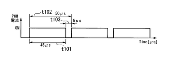
- the duty ratio III corresponds to a duty ratio of 90%.
- the PWM cycle corresponding to the maximum frequency fmax of 20 [kHz] is 50 [ ⁇ sec].
- the frequency variable unit 201 determines that the acquired luminance information is within the range of the duty ratio I based on the PWM variable characteristic (FIG. 4) stored in the storage unit 202. Next, the frequency variable unit 201 determines time information based on the determined result and selects a PWM frequency.
- the PWM waveform generation unit 203 maintains the minimum on-time at 5 [ ⁇ sec] as shown in FIG. 6 according to the time information output from the frequency variable unit 201 and the PWM frequency, and the maximum frequency of the PWM frequency.
- a drive signal whose fmax is less than 20 [kHz] is generated.
- the duty ratio can be 5% while maintaining the minimum on-time at 5 [ ⁇ sec].
- the luminance can be lowered by lowering the PWM frequency and reducing the on-time ratio than the duty ratio II.
- the PWM waveform generator 203 maintains the minimum on-time at 5 [ ⁇ sec] and generates a drive signal with a PWM frequency of 10 [kHz].
- the frequency variable unit 201 determines that the acquired luminance information is within the range of the duty ratios II to III based on the PWM variable characteristics stored in the storage unit 202. Next, the frequency variable unit 201 determines time information based on the determined result and selects a PWM frequency.
- the frequency variable unit 201 determines the on-time t101 as a duty ratio corresponding to the luminance information.
- the PWM waveform generation unit 203 sets the ON time according to the luminance information to 5 [ ⁇ sec] to 45 [45] according to the time information output from the frequency variable unit 201 and the PWM frequency, as shown in FIGS. [mu] sec], and a drive signal having a maximum PWM frequency fmax of 20 [kHz] is generated.
- the frequency variable unit 201 determines that the acquired luminance information is within the range of the duty ratio IV based on the PWM variable characteristic stored in the storage unit 202.
- the frequency variable unit 201 determines time information based on the determined result and selects a PWM frequency.
- the frequency variable unit 201 determines the off time t103 as 5 [ ⁇ sec] as the minimum off time stored in the storage unit 202.
- the PWM waveform generation unit 203 maintains the minimum off time at 5 [ ⁇ sec] as shown in FIG. 9 according to the time information output from the frequency variable unit 201 and the PWM frequency, and the maximum frequency of the PWM frequency.
- a drive signal whose fmax is less than 20 [kHz] is generated.
- the duty ratio can be 95% while maintaining the minimum off time at 5 [ ⁇ sec].
- the luminance can be increased by lowering the PWM frequency and increasing the on-time ratio than the duty ratio III.
- the PWM waveform generation unit 203 maintains a minimum off time at 5 [ ⁇ sec] and generates a drive signal having a PWM frequency of 10 [kHz].
- the first range in which the range of the duty ratio of the drive signal that is a pulse signal for driving the light source of the backlight is predetermined and the third in which the range is predetermined.
- the frequency of the drive signal is changed based on the luminance of the light source
- the drive control for fixing the frequency of the drive signal to a predetermined frequency A part in the display device of the present embodiment, fixes the ON time during which the pulses in the drive signal are in the ON state in the first range, and sets the frequency of the drive signal to a predetermined value based on the luminance of the light source.
- the duty ratio of the drive signal is changed based on the luminance.
- the off-time during which the pulses in the drive signal are off is fixed and the luminance is set. Based on this, the frequency of the drive signal is changed to be lower than a predetermined frequency.
- the PWM frequency is determined to be less than the maximum frequency fmax. To do. Furthermore, in the display device 1 according to the present embodiment, when the user specifies brightness outside the range where the drive unit 30 can be driven at the maximum frequency fmax of the PWM frequency, the on-time is stored in the storage unit 202. The minimum on time is determined, or the off time is determined as the minimum off time stored in the storage unit 202.
- the display apparatus 1 of this embodiment since it can adjust a brightness
- the conventional luminance adjustment range is, for example, 20% to 80%
- the luminance adjustment range is expanded to, for example, 0.2% to 98.8% as described below. can do.
- FIG. 10 is a diagram for explaining the relationship between PWM On Duty and display luminance in the comparative example.
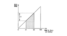
- FIG. 11 is a diagram for explaining the relationship between PWM On Duty and display luminance according to the present embodiment. 10 and 11, the horizontal axis represents PWM On Duty, and the vertical axis represents display luminance.
- FIG. 10 is an example of the display luminance range by the driving method of the comparative example in which only the duty ratio is changed when the PWM frequency is fixed.
- FIG. 11 is an example of a display luminance range with the driving method according to the present embodiment. In FIG. 10 and FIG. 11, the components constituting the drive unit 30 are the same.
- the duty ratio d1 is a duty ratio determined by the minimum on-time that can be driven by the components constituting the drive unit 30.
- the duty ratio d2 is a duty ratio determined by the minimum off time that can be driven by the components constituting the drive unit 30.
- the duty ratio d1 is, for example, about 0.2%
- the duty ratio d2 is about 99.8%.
- the PWM frequency becomes 100 times, so the duty ratio d1 is
- the on-time is too short in the duty ratio range of 0% to d1, so that the drive unit 30 cannot generate a drive signal, and the display device 1 performs brightness adjustment. I can't.
- the drive unit 30 in the range of the duty ratio d2 to 100%, since the off time is too short, the drive unit 30 cannot generate a drive signal, and the display device 1 cannot perform brightness adjustment.
- the PWM frequency is increased in order to reduce flicker, the minimum on time and the minimum off time cannot be shortened accordingly, and thus the brightness adjustment range becomes narrow.
- the on-time of the duty ratio d1 is maintained in the range of the duty ratio I.
- the PWM frequency is changed.
- the range in which the start adjustment is possible can be expanded from the duty ratio d1 to d11.
- the PWM frequency is changed while maintaining the off time of the duty ratio d12 in the range of the duty ratio IV.
- the range in which the start adjustment is possible can be expanded from the duty ratio d2 to d12.
- PWM control is performed with the duty ratio based on the luminance information instructed by the user, and the range including the vicinity where the duty ratio is near 0% or near 100%. If it is within the range, the on time or the off time is fixed and the PWM frequency is changed.
- the drive voltage is converted from 5V to 3.3V and output.
- the PWM frequency is set higher than a predetermined frequency in order to reduce flicker and the OFF time of the PWM waveform is shortened in order to increase the brightness, an overvoltage may be supplied to the LED.
- the PWM frequency cannot be changed in the vicinity of 100%.
- the PWM frequency can be changed even in the vicinity of a duty ratio of 100%.
- the on time and the off time that can be driven are limited depending on the specifications of the components used in the drive unit 30.
- the on-time and the off-time change the PWM frequency to be less than the maximum frequency fmax while maintaining the time limited by the components, so that the drive unit 30 can be used without using expensive components. Can be configured. As a result, the cost of the display device 1 can be reduced.
- the frequency variable unit 201 determines whether the luminance information output from the brightness specifying unit 10 is in the range of any of the duty ratios I, II to III, or IV, and PWM Although the example which determines the ON time or OFF time which the waveform generation part 203 uses is demonstrated, it is not restricted to this.
- the PWM waveform generation unit 203 may perform such determination and determination based on information stored in the storage unit 202.
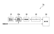
- FIG. 12 is a block diagram of a schematic configuration of the display device 1a according to the present embodiment.
- the display device 1 a includes a brightness designation unit 10, a drive control unit 20 a, a drive unit 30, a backlight 40, and a display unit 50.
- a display unit 50 is abbreviate
- the drive control unit 20a generates a drive signal for PWM driving based on the luminance information output from the brightness specifying unit 10 and the frequency of the synchronization signal Vsync included in the video signal, and drives the generated drive signal. To the unit 30.
- the frequency of the synchronization signal Vsync is 60 [Hz], for example.
- FIG. 13 is a block diagram of a schematic configuration of the drive control unit 20a according to the present embodiment.
- the drive control unit 20a includes a frequency variable unit 201a, a storage unit 202, and a PWM waveform generation unit 203.
- a frequency variable unit 201a As shown in FIG. 13, the drive control unit 20a includes a frequency variable unit 201a, a storage unit 202, and a PWM waveform generation unit 203.
- symbol is abbreviate
- the frequency variable unit 201a acquires the luminance information output from the brightness specifying unit 10.
- the frequency variable unit 201a uses the PWM variable characteristic stored in the storage unit 202 to determine which duty ratio range the acquired luminance information is.
- the frequency variable unit 201 a determines time information for generating the PWM waveform based on the determined result, and outputs the determined time information to the PWM waveform generation unit 203.
- the frequency variable unit 201a selects the PWM frequency based on the PWM variable characteristic stored in the storage unit 202. After selecting the PWM frequency, the frequency variable unit 201a calculates the selected PWM frequency so that the PWM frequency is an integral multiple of the frequency of the synchronization signal Vsync included in the video signal. The frequency variable unit 201 a outputs the calculated PWM frequency to the PWM waveform generation unit 203.
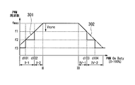
- FIG. 14 is a diagram illustrating an example of selection and calculation of the PWM frequency performed by the frequency variable unit 201a according to the present embodiment.
- the horizontal axis represents PWM On Duty
- the vertical axis represents PWM frequency.
- the horizontal axis PWM On Duty is 0% on the left and 100% on the right.
- the maximum frequency fmax is an integral multiple of the frequency of the synchronization signal Vsync when it is equal to or lower than the predetermined frequency, and may not be an integral multiple of the frequency of the synchronization signal Vsync when it is greater than the predetermined frequency.
- the maximum frequency fmax is, for example, 19.98 [kHz] when it is an integral multiple of the frequency 60 [Hz] of the synchronization signal Vsync.
- the PWM frequency is an integral multiple of the synchronization signal Vsync with respect to the PWM On Duty within the range of the duty ratios I and IV.
- PWM frequencies f1 to f3 are lower than the straight line of the PWM On Duty vs. PWM frequency change at the duty ratios I and IV in the PWM variable characteristics shown in FIG. 4 as indicated by alternate long and short dashed lines 301 and 302 in FIG. Is the frequency.
- the frequency variable unit 201a stores in advance the relationship between the PWM On Duty and the PWM frequency shown in FIG. 14, and uses this stored relationship so that the PWM frequency becomes an integral multiple of the frequency of the synchronization signal Vsync. It may be calculated. Note that the relationship between the PWM On Duty and the PWM frequency shown in FIG. 14 may be stored in the storage unit 202.
- the frequency variable unit 201a determines that the acquired luminance information is within the range of the duty ratio I. And the frequency variable part 201a selects the PWM frequency according to luminance information in the range of the duty ratio I based on the PWM variable characteristic shown in FIG. In other words, the frequency variable unit 201a selects the PWM frequency on the alternate long and short dash line 301 in FIG. Next, the frequency variable unit 201a calculates the selected PWM frequency to f2, which is an integer multiple of the frequency of the synchronization signal Vsync.
- the frequency variable unit 201a determines that the acquired luminance information is within the range of the duty ratio IV. And the frequency variable part 201a selects the PWM frequency according to luminance information in the range of the duty ratio IV based on the PWM variable characteristic shown in FIG. In other words, the frequency variable unit 201a selects the PWM frequency on the alternate long and short dash line 302 in FIG. Next, the frequency variable unit 201a calculates the selected PWM frequency to f1, which is an integer multiple of the frequency of the synchronization signal Vsync.
- the PWM frequency in the range of the duty ratio I and the range of the duty ratio IV may be an integer multiple of the frequency of the synchronization signal Vsync.
- the PWM frequency selected by the frequency variable unit 201a may be fmax ⁇ Vsync ⁇ 1 when the duty ratio is d102 to II, and fmax ⁇ Vsync ⁇ 3 when the duty ratio is d101 to d102.
- the PWM frequency selected by the frequency variable unit 201a may be fmax ⁇ Vsync ⁇ 2 when the duty ratio is III to d103, and fmax ⁇ Vsync ⁇ 4 when the duty ratio is d103 to d104.
- the PWM frequency in the range of the duty ratio I and the range of the duty ratio IV may be changed in different ways.
- the frequency variable unit 201a calculates a PWM frequency such that the PWM frequency is an integer multiple of the frequency of the synchronization signal Vsync in a range less than the duty ratio II or greater than the duty ratio III.
- FIG. 15 is a flowchart illustrating a processing procedure of the drive control unit 20a according to the present embodiment.
- Step S101 The frequency variable unit 201a of the drive control unit 20a acquires the luminance information output by the brightness specifying unit 10.
- Step S ⁇ b> 102 The frequency variable unit 201 a uses the PWM variable characteristic stored in the storage unit 202 to determine which duty ratio range the acquired luminance information is. The frequency variable unit 201a determines time information based on the determination result. Next, the frequency variable unit 201a selects the PWM frequency (1) based on the PWM variable characteristic (FIG. 4) stored in the storage unit 202.
- Step S103 The frequency variable unit 201a determines whether or not the PWM frequency (1) selected in step S102 is the maximum frequency fmax. When the PWM frequency (1) is the maximum frequency fmax, the frequency variable unit 201a sets the PWM frequency (1) as the PWM frequency (2). When the PWM frequency (1) is not the maximum frequency fmax, the frequency variable unit 201a calculates the PWM frequency (2) that is an integral multiple of the frequency of the synchronization signal Vsync included in the video signal.
- Step S104 The frequency variable unit 201a outputs the determined time information and the calculated PWM frequency (2) to the PWM waveform generation unit 203.
- Step S105 The PWM waveform generation unit 203 acquires the luminance information output from the brightness specifying unit 10, and acquires the time information output from the frequency variable unit 201a and the PWM frequency (2).
- the PWM waveform generation unit 203 generates a drive signal based on the acquired time information and the PWM frequency (2), and outputs the generated drive signal to the drive unit 30.
- the drive control unit changes the frequency of the drive signal according to the frequency of the synchronization signal included in the input video signal.
- the display device 1a of the present embodiment can perform display in a wider luminance range than in the past, as in the first embodiment.
- the PWM frequency is changed to be an integral multiple of the frequency of the synchronization signal Vsync, so that interference noise with the video signal can be reduced.
- the frequency variable unit 201a calculates the PWM frequency so as to be an integral multiple of the frequency of the synchronization signal Vsync when the frequency is lower than the predetermined frequency. If the frequency is higher than the predetermined frequency, the frequency variable unit 201a converts the PWM frequency to the synchronization signal Vsync.
- the PWM frequency may be selected as it is without being calculated to be an integral multiple of the frequency.
- the reason for not calculating the PWM frequency is that flickering is not felt when the PWM frequency is increased. For this reason, the predetermined frequency may be determined in advance by experiments.
- the present invention is not limited to this.
- the range may be three or more.
- the PWM frequency when the PWM frequency is changed to be an integral multiple of the frequency of the synchronization signal Vsync, it may be divided into five ranges.
- FIG. 16 is a diagram illustrating an example of the relationship between PWM On Duty and PWM frequency when the duty ratio is divided into five ranges.
- the horizontal axis represents the PWM On Duty in the PWM waveform
- the vertical axis represents the PWM frequency.
- the first range is the range of the duty ratio I-1 shown in FIG. 16, the PWM On Duty is 0 to d102, that is, the duty ratio is near 0%, and the PWM frequency is predetermined. It is less than the range.
- the frequency variable unit 201a may fix the minimum ON time and calculate the PWM frequency so as to be an integral multiple of the frequency of the synchronization signal Vsync.
- the second range is a range of the duty ratio I ⁇ 2, the PWM On Duty is d102 to III, that is, the duty ratio is in the vicinity of 0%, and the PWM frequency is equal to or higher than a predetermined frequency. In this second range, the frequency variable unit 201a may be fixed at the minimum on-time and change the PWM frequency.
- the third range is a range of duty ratios II to III, that is, a range in which the duty ratio includes around 50%, and the PWM frequency is a range of the maximum frequency fmax.
- the frequency variable unit 201a may change the on-time according to the luminance information and fix the PWM frequency.
- the fourth range is a range of the duty ratio IV-1, where the PWM On Duty is III to d103, that is, the range where the duty ratio is near 100% and the PWM frequency is equal to or higher than a predetermined frequency.
- the frequency variable unit 201a may fix the off time to the minimum off time and change the PWM frequency.
- the fifth range is the range of the duty ratio IV-2, the PWM On Duty is d104 to 100, that is, the range where the duty ratio is near 100% and the PWM frequency is less than the predetermined frequency.
- the frequency variable unit 201a may fix the off time to the minimum off time and calculate the PWM frequency so as to be an integral multiple of the frequency of the synchronization signal Vsync.
- the backlight 40 may generate white color by mixing light of three light sources, for example, a red LED, a green LED, and a blue LED.
- the drive unit 30 may have separate drive units for red, green, and blue LEDs. Then, when the duty ratio is less than the minimum on-time or less than the minimum off-time, the drive control unit 20 (including 20a) selects the PWM frequency for each color according to the luminance information output by the brightness designation unit 10. You may make it do. Then, the drive control unit 20 (including 20a) may output the PWM frequency of each selected color to the drive unit 30.
- the frequency variable unit 201 selects the PWM frequency.
- the frequency variable unit 201 may select the time of the PWM cycle corresponding to the PWM frequency, or may be calculated so as to be an integral multiple of the time corresponding to the cycle of the synchronization signal Vsync.
- the drive control unit 20 (including 20a) is used to control the backlight of the display device 1 (including 1a) has been described, but the present invention is not limited thereto.
- the drive control unit 20 may be used to control a light source such as a projector or a laser TV.
- the display device 1 (including 1a) of the present embodiment may be applied to a portable information terminal, a navigation system, a notification lamp, a digital signage (Digital Signage), and the like.
- a program for realizing the functions of the drive control unit 20 in FIGS. 1 and 3 of the embodiment or the drive control unit 20a in FIGS. 12 and 13 is recorded on a computer-readable recording medium. Processing of each unit may be performed by reading a recorded program into a computer system and executing the program.
- the “computer system” includes an OS and hardware such as peripheral devices. Further, the “computer system” includes a homepage providing environment (or display environment) if a WWW system is used.
- the “computer-readable recording medium” is a portable medium such as a flexible disk, a magneto-optical disk, a ROM (Read Only Memory), a CD-ROM, or a USB (Universal Serial Bus) I / F (interface).
- a storage device such as a USB memory or a hard disk built in a computer system.
- the “computer-readable recording medium” includes a medium that holds a program for a certain period of time, such as a volatile memory inside a computer system serving as a server or a client.
- the program may be a program for realizing a part of the functions described above, and may be a program capable of realizing the functions described above in combination with a program already recorded in a computer system.
Landscapes
- Engineering & Computer Science (AREA)
- Physics & Mathematics (AREA)
- Computer Hardware Design (AREA)
- General Physics & Mathematics (AREA)
- Theoretical Computer Science (AREA)
- Chemical & Material Sciences (AREA)
- Crystallography & Structural Chemistry (AREA)
- Liquid Crystal (AREA)
- Liquid Crystal Display Device Control (AREA)
- Control Of Indicators Other Than Cathode Ray Tubes (AREA)
Abstract
表示装置は、バックライトの光源を駆動するためパルス信号である駆動信号のデューティ比の範囲が予め定められている第1の範囲及び予め定められている第3の範囲では、光源の輝度に基づいて駆動信号の周波数を変更し、駆動信号のデューティ比の範囲が予め定められている第2の範囲では、駆動信号の周波数を所定の周波数に固定する駆動制御部を備える。
Description
本発明は、表示装置、および表示装置の制御方法に関する。
液晶表示装置は、液晶層、バックライト装置などで構成されている。このような液晶表示装置におけるバックライト装置として、白色光を用いるものがある。また、近年のバックライト装置では、その光源としてLED(発光ダイオード)が用いられている。
液晶表示装置のバックライト装置の光源としてLEDを用いた場合、このLEDは、例えば、PWM(Pulse Width Modulation;パルス幅変調)で駆動される(例えば、特許文献1参照)。このPWM駆動では、LEDに入力するパルス幅を制御することによって、LEDの輝度、すなわち光源として用いられるバックライトの輝度を制御している。
また、LEDは、従来光源として用いられている蛍光管に比べて残像時間が短い。このため、LEDを用いた照明機器では、光出力のちらつき(フリッカー)による利用者の体調不良等を防止するための基準が定められている(例えば、非特許文献1参照)。この基準では、光出力のちらつきを感じないものとされる技術基準が定められている。なお、非特許文献1では、繰り返し周波数が100[Hz]以上で光出力に欠落部がない又は繰り返し周波数が500[Hz]以上のものは、「ちらつきを感じないもの」と解釈すると記載されている。このことからLEDを用いたバックライト装置では、PWMの駆動(以下、PWM駆動という)による制御をした場合、繰り返し周波数が低いと、LED照明機器と同様のちらつきが発生すると考えられる。従って、LEDを用いたバックライト装置で、ちらつきを低減するためには、PWM駆動における繰り返し周波数を高くする必要がる。
http://www.meti.go.jp/policy/consumer/seian/denan/kaisei_setsumeikai201205.pdf 、"電気用品安全法の改正政省令施行について"、経済産業省 商務流通グループ 製品安全課、平成24年5月(2013年5月8日、インターネット検索)
しかしながら、ちらつきを低減するためにPWMでLEDを駆動する周波数を高くした場合、輝度を調整するために制御するLEDがオン状態またはオフ状態の期間が、LEDを駆動するための駆動回路によって制限されるため、LEDをバックライトとして組み込んだ表示装置において表示することができる画像の輝度の範囲が限られてしまうという問題点があった。
本発明は、上記の問題点に鑑みてなされたものであって、LEDを光源として用いたバックライト装置を組み込んだ表示装置において表示可能な輝度の範囲を改善することができる表示装置、および表示装置の制御方法を提供することを目的としている。
上記目的を達成するため、本発明に係る表示装置は、バックライトの光源を駆動するためパルス信号である駆動信号のデューティ比の範囲が予め定められている第1の範囲及び予め定められている第3の範囲では、前記光源の輝度に基づいて前記駆動信号の周波数を変更し、前記駆動信号のデューティ比の範囲が予め定められている第2の範囲では、前記駆動信号の周波数を所定の周波数に固定する駆動制御部を備える。
上記目的を達成するため、本発明に係る表示装置の制御方法は、バックライトの光源を駆動するためパルス信号である駆動信号のデューティ比の範囲が予め定められている第1の範囲及び予め定められている第3の範囲では、前記光源の輝度に基づいて前記駆動信号の周波数を変更する手順と、前記駆動信号のデューティ比の範囲が予め定められている第2の範囲では、前記駆動信号の周波数を所定の周波数に固定する手順と、を含む。
本発明の表示装置は、LEDを光源として用いたバックライト装置を組み込んだ表示装置において表示可能な輝度の範囲を改善することができる。
[第1実施形態]
以下、図面を用いて本発明の実施形態について詳細に説明する。
図1は、本実施形態に係る表示装置1の概略構成のブロック図である。図1に示すように表示装置1は、明るさ指定部10、駆動制御部20、駆動部30、バックライト40、および表示部50を備えている。
以下、図面を用いて本発明の実施形態について詳細に説明する。
図1は、本実施形態に係る表示装置1の概略構成のブロック図である。図1に示すように表示装置1は、明るさ指定部10、駆動制御部20、駆動部30、バックライト40、および表示部50を備えている。
明るさ指定部10は、利用者によって指定された明るさ(輝度)を受け付け、受け付けた明るさを示す情報(以下、輝度情報という)を駆動制御部20に出力する。なお、明るさ指定部10は、指定された明るさに応じたPWM(Pulse Width Modulation;パルス幅変調)のオン時間であるデューティサイクル(duty cycle)を輝度情報として、駆動制御部20に出力する。なお、以下では、デューティサイクル(duty cycle)を、デューティ比という。明るさ指定部10は、例えば、本体に設けられているスイッチやリモコン受光部を含む。
なお、表示部50が輝度を測定するセンサを有している場合、明るさ指定部10が出力する輝度情報は、センサが測定した輝度の測定値を、利用者が指定した輝度に保つようにするデューティ比であってもよい。また、センサは、輝度の測定を行うときのみ表示部50に取り付けられるようにしてもよい。そして、センサが輝度を測定するタイミングは、予め定められている周期、予め定められている日時、ランダム、利用者により指定されたとき等であってもよい。なお、輝度情報は、バックライト40の光源の輝度を含むターゲット値であって、利用者によって指定された輝度、またはセンサによって測定された輝度であってもよい。
駆動制御部20は、明るさ指定部10が出力した輝度情報を取得し、取得した輝度情報に基づいて、バックライト40をPWMで駆動(以下、PWM駆動という)するための駆動信号を生成し、生成した駆動信号を駆動部30に出力する。なお、PWM駆動は、電流駆動であっても、電圧駆動であってもよい。
駆動部30は、駆動制御部20が生成した駆動信号に応じてバックライト40を駆動する。
駆動部30は、駆動制御部20が生成した駆動信号に応じてバックライト40を駆動する。
バックライト40は、白色のLED(発光ダイオード)から構成され、駆動部30が出力した駆動信号によって発光する。バックライト40は、例えば、表示部50の背面に取り付けられている。または、バックライト40は、表示部50の下部に取り付けられ、表示部50内の導光板と光拡散フィルム等によって、発光した光が拡散される。
表示部50は、例えば液晶表示器などの表示器からなり、表示装置1に入力された映像信号を表示器上に表示する。なお、表示部50は、入力された映像信号を表示器上に表示するための画像処理部を有している。なお、映像信号は、例えば、PC(パーソナルコンピュータ)等の映像出力装置から供給される。
図2は、本実施形態に係る駆動制御部20が駆動部30に出力する駆動信号を説明するための図である。図2において、横軸は時間、縦軸は駆動信号の電流(バックライト電流とも言う)である。なお、駆動信号がハイレベルの期間をオン状態といい、ローレベルの期間をオフ状態という。
図2において、時刻t1~t2の期間t11は、PWM駆動におけるパルスがオン状態の期間(以下、オン時間ともいう)である。時刻t2~t3の期間t12は、パルスがオフ状態の期間(以下、オフ時間ともいう)である。また、期間t11と期間t12の合計の期間t13は、パルス波形における1周期(以下、PWM周期と言う)である。例えば、期間t11が5[μsec]、期間t12が45[μsec]の場合、PWM周期t13は50[μsec](=5+45)であり、デューティ比は10%(=5/50×100)である。なお、以下の説明では、PWM周期の逆数を、PWM周波数と言う。図2の例では、PWM周波数は、20kHz(=1/50[μsec])である。また、PWM駆動におけるパルス波形をPWM波形という。
図2に示したようなPWM波形を用いてバックライト40のLEDを駆動する場合、PWM周波数が所定の周波数以上であれば、ちらつきが低減される。また、オン時間の長さを変更することで、バックライト40のLEDの輝度を変更することができる。なお、オン時間が長いほどバックライト40のLEDの輝度が高くなり、オン時間が短いほどLEDの輝度が低くなる。
図3は、本実施形態に係る駆動制御部20の概略構成のブロック図である。図2に示すように、駆動制御部20は、周波数可変部201、記憶部202、およびPWM波形生成部203を備えている。
記憶部202には、最小のオン時間、最小のオフ時間、PWM周波数の最大周波数、およびPWM可変特性が記憶されている。PWM可変特性については後述する。ここで、最小のオン時間および最小のオフ時間は、例えば駆動部30が駆動できる最小パルス幅やバックライト40に入力できる最小のパルス幅等に基づいて決定される値である。また、PWM周波数の最大周波数は、駆動部30が駆動できる最大周波数やバックライト40に入力できる最大周波数等に基づいて決定される値である。
周波数可変部201は、明るさ指定部10が出力した輝度情報を取得する。周波数可変部201は、記憶部202に記憶されているPWM可変特性を用いて、取得した輝度情報が、いずれのデューティ比の範囲であるか判別する。なお、デューティ比の範囲については、後述する。周波数可変部201は、判別した結果に基づいて、PWM波形を生成するための時間の情報を決定し、決定した時間の情報をPWM波形生成部203に出力する。ここで、周波数可変部201が出力する時間の情報は、以下の(1)~(3)の3つのうちのいずれか1つである。
(1)オン時間として最小のオン時間を使用することを示す情報
(2)オン時間として輝度情報を使用することを示す情報
(3)オフ時間として最小のオフ時間を使用することを示す情報
また、周波数可変部201は、記憶部202に記憶されているPWM可変特性に基づいて、PWM周波数を選択し、選択したPWM周波数をPWM波形生成部203に出力する。
(1)オン時間として最小のオン時間を使用することを示す情報
(2)オン時間として輝度情報を使用することを示す情報
(3)オフ時間として最小のオフ時間を使用することを示す情報
また、周波数可変部201は、記憶部202に記憶されているPWM可変特性に基づいて、PWM周波数を選択し、選択したPWM周波数をPWM波形生成部203に出力する。
PWM波形生成部203は、明るさ指定部10が出力した輝度情報を取得する。PWM波形生成部203は、取得した輝度情報と、周波数可変部201が出力した時間の情報とPWM周波数とに基づいて、駆動信号を生成し、生成した駆動信号を駆動部30に出力する。PWM波形生成部203は、時間の情報が、オン時間として最小のオン時間を使用することを示す情報の場合、最小のオン時間を維持し且つPWM周波数の周期を有する駆動信号を生成する。または、PWM波形生成部203は、時間の情報が、オン時間として輝度情報を使用することを示す情報の場合、輝度情報のデューティ比に応じた時間のオン時間且つPWM周波数の周期を有する駆動信号を生成する。あるいは、PWM波形生成部203は、時間の情報が、オフ時間として最小のオフ時間を使用することを示す情報の場合、最小のオフ時間を維持し且つPWM周波数の周期を有する駆動信号を生成する。
ここで、記憶部202に記憶されているPWM可変特性の一例について説明する。図4は、本実施形態に係る記憶部202に記憶されているPWM可変特性の一例を説明する図である。図4において、横軸はPWM波形におけるオン状態のデューティ比(PWM On Dutyとも言う)、縦軸はPWM周波数である。なお、横軸のPWM On Dutyは、左が0%、右が100%である。
図4において、デューティ比IIは、最小のオン時間に対応するPWM On Dutyを表し、デューティ比IIIは、最小のオフ時間に対応するPWM On Dutyを表している。デューティ比Iの範囲(PWM On Dutyが0%より大きくII未満)では、PWM On Dutyの増加に伴い、PWM周波数がfmin~fmaxに増加するように、PWM On DutyとPWM周波数とが関連づけられて記憶されている。また、デューティ比II~IIIの範囲では、PWM周波数は、最大周波数fmaxがPWM On Dutyと関連づけられて記憶されている。また、デューティ比IVの範囲(PWM On DutyがIIIより大きく100%未満)は、PWM On Dutyの増加に伴い、PWM周波数がfmax~fminに減少するように、PWM On DutyとPWM周波数とが関連づけられて記憶されている。以上のように、本実施形態において、周波数可変部201は、デューティ比を3つの範囲に分けた場合、デューティ比Iの範囲で、オン時間を最小のオン時間に維持したままPWM周波数を変更し、デューティ比II~IIIの範囲で、PWM周波数を固定したままオン時間を変更し、デューティ比IVの範囲で、オフ時間を最小のオフ時間を維持したままPWM周波数を変更する。
なお、このPWM可変特性は、数式によって、記憶部202に記憶されていてもよい。また、最大周波数fmaxは、映像信号に含まれる同期信号Vsyncの周波数の略整数倍であってもよい。
なお、このPWM可変特性は、数式によって、記憶部202に記憶されていてもよい。また、最大周波数fmaxは、映像信号に含まれる同期信号Vsyncの周波数の略整数倍であってもよい。
ここで、周波数可変部201が、時間の情報を決定し、PWM周波数を選択する例を説明する。一例として、デューティ比IIがPWM On Duty10%、デューティ比IIIがPWM On Duty90%、PWM周波数の最大周波数fmaxが20[kHz]の場合を説明する。
明るさ指定部10が出力した輝度情報であるPWM On Dutyが5%の場合、周波数可変部201は、PWM可変特性に基づいて、輝度情報がデューティ比Iの範囲であると判別する。そして、周波数可変部201は、PWM可変特性に基づいて、PWM On Duty5%に応じたPWM周波数を選択する。また、周波数可変部201は、輝度情報がデューティ比Iの範囲であるため、オン時間を、記憶部202に記憶されている最小のオン時間に決定する。
明るさ指定部10が出力した輝度情報であるPWM On Dutyが5%の場合、周波数可変部201は、PWM可変特性に基づいて、輝度情報がデューティ比Iの範囲であると判別する。そして、周波数可変部201は、PWM可変特性に基づいて、PWM On Duty5%に応じたPWM周波数を選択する。また、周波数可変部201は、輝度情報がデューティ比Iの範囲であるため、オン時間を、記憶部202に記憶されている最小のオン時間に決定する。
また、明るさ指定部10が出力した輝度情報であるPWM On Dutyが50%の場合、周波数可変部201は、PWM可変特性に基づいて、デューティ比II~IIIの範囲であると判別する。そして、周波数可変部201は、PWM可変特性に基づいて、PWM周波数として最大周波数fmaxを選択する。また、周波数可変部201は、輝度情報がデューティ比II~IIIの範囲であるため、オン時間を、明るさ指定部10が出力した輝度情報に応じたPWM On Duty50%に決定する。
また、明るさ指定部10が出力した輝度情報であるPWM On Dutyが95%の場合、周波数可変部201は、PWM可変特性に基づいて、デューティ比IVの範囲であると判別する。そして、周波数可変部201は、PWM可変特性に基づいて、PWM On Duty95%に応じたPWM周波数を選択する。また、周波数可変部201は、輝度情報がデューティ比IVの範囲であるため、オフ時間を、記憶部202に記憶されている最小のオフ時間に決定する。
また、明るさ指定部10が出力した輝度情報であるPWM On Dutyが95%の場合、周波数可変部201は、PWM可変特性に基づいて、デューティ比IVの範囲であると判別する。そして、周波数可変部201は、PWM可変特性に基づいて、PWM On Duty95%に応じたPWM周波数を選択する。また、周波数可変部201は、輝度情報がデューティ比IVの範囲であるため、オフ時間を、記憶部202に記憶されている最小のオフ時間に決定する。
次に、駆動制御部20の処理手順を説明する。図5は、本実施形態に係る駆動制御部20の処理手順を示すフローチャートである。
(ステップS1)駆動制御部20の周波数可変部201は、明るさ指定部10が出力した輝度情報を取得する。
(ステップS1)駆動制御部20の周波数可変部201は、明るさ指定部10が出力した輝度情報を取得する。
(ステップS2)周波数可変部201は、記憶部202に記憶されているPWM可変特性を用いて、取得した輝度情報が、いずれのデューティ比の範囲であるか判別する。
取得した輝度情報がデューティ比Iの範囲である場合、周波数可変部201は、オン時間として最小のオン時間を使用することを示す情報を時間の情報として決定し、記憶部202に記憶されているPWM可変特性に基づいて、PWM周波数を最大周波数fmax未満に選択する。
または、取得した輝度情報がデューティ比II~IIIの範囲である場合、周波数可変部201は、オン時間として輝度情報を使用することを示す情報を時間の情報として決定し、記憶部202に記憶されているPWM可変特性に基づいて、PWM周波数を最大周波数fmaxに選択する。
あるいは、取得した輝度情報がデューティ比IVの範囲である場合、周波数可変部201は、オフ時間として最小のオフ時間を使用することを示す情報を時間の情報として決定し、記憶部202に記憶されているPWM可変特性に基づいて、PWM周波数を最大周波数fmax未満に選択する。
取得した輝度情報がデューティ比Iの範囲である場合、周波数可変部201は、オン時間として最小のオン時間を使用することを示す情報を時間の情報として決定し、記憶部202に記憶されているPWM可変特性に基づいて、PWM周波数を最大周波数fmax未満に選択する。
または、取得した輝度情報がデューティ比II~IIIの範囲である場合、周波数可変部201は、オン時間として輝度情報を使用することを示す情報を時間の情報として決定し、記憶部202に記憶されているPWM可変特性に基づいて、PWM周波数を最大周波数fmaxに選択する。
あるいは、取得した輝度情報がデューティ比IVの範囲である場合、周波数可変部201は、オフ時間として最小のオフ時間を使用することを示す情報を時間の情報として決定し、記憶部202に記憶されているPWM可変特性に基づいて、PWM周波数を最大周波数fmax未満に選択する。
(ステップS3)周波数可変部201は、決定した時間の情報と選択したPWM周波数をPWM波形生成部203に出力する。
(ステップS4)PWM波形生成部203は、明るさ指定部10が出力した輝度情報を取得し、周波数可変部201が出力した時間の情報とPWM周波数を取得する。次に、PWM波形生成部203は、取得した時間の情報とPWM周波数とに基づいて駆動信号を生成し、生成した駆動信号を駆動部30に出力する。
時間の情報が最小のオン時間を使用することを示す情報の場合、PWM波形生成部203は、明るさ指定部10が出力した輝度情報を用いず、最小のオン時間を維持したまま、PWM周波数に応じた駆動信号を生成する。または、時間の情報が輝度情報を使用することを示す情報の場合、PWM波形生成部203は、輝度情報に応じたオン時間、およびPWM周波数に応じた駆動信号を生成する。あるいは、時間の情報が最小のオフ時間を使用することを示す情報の場合、PWM波形生成部203は、明るさ指定部10が出力した輝度情報を用いず、最小のオフ時間を維持したまま、PWM周波数に応じた駆動信号を生成する。
(ステップS4)PWM波形生成部203は、明るさ指定部10が出力した輝度情報を取得し、周波数可変部201が出力した時間の情報とPWM周波数を取得する。次に、PWM波形生成部203は、取得した時間の情報とPWM周波数とに基づいて駆動信号を生成し、生成した駆動信号を駆動部30に出力する。
時間の情報が最小のオン時間を使用することを示す情報の場合、PWM波形生成部203は、明るさ指定部10が出力した輝度情報を用いず、最小のオン時間を維持したまま、PWM周波数に応じた駆動信号を生成する。または、時間の情報が輝度情報を使用することを示す情報の場合、PWM波形生成部203は、輝度情報に応じたオン時間、およびPWM周波数に応じた駆動信号を生成する。あるいは、時間の情報が最小のオフ時間を使用することを示す情報の場合、PWM波形生成部203は、明るさ指定部10が出力した輝度情報を用いず、最小のオフ時間を維持したまま、PWM周波数に応じた駆動信号を生成する。
次に、駆動制御部20の動作の一例を、図3、図4、図6~図9を用いて説明する。図6は、本実施形態に係る図4のデューティ比Iの範囲における駆動信号の一例を説明する図である。図7は、本実施形態に係る本実施形態に係る図4のデューティ比IIにおける駆動信号の一例を説明する図である。図8は、本実施形態に係る本実施形態に係る図4のデューティ比IIIにおける駆動信号の一例を説明する図である。図9は、本実施形態に係る本実施形態に係る図4のデューティ比IVの範囲における駆動信号の一例を説明する図である。図6~図9において、横軸は時間、縦軸はPWMの駆動信号の電流レベルである。
なお、以下の説明では、最小のオン時間が5[μsec]、最小のオフ時間が5[μsec]、PWM周波数の最大周波数fmaxが20[kHz]である場合について説明する。このため、デューティ比IIは、デューティ比が10%に相当し、デューティ比IIIは、デューティ比が90%に相当する。なお、最大周波数fmaxが20[kHz]に対応するPWM周期は、50[μsec]である。
なお、以下の説明では、最小のオン時間が5[μsec]、最小のオフ時間が5[μsec]、PWM周波数の最大周波数fmaxが20[kHz]である場合について説明する。このため、デューティ比IIは、デューティ比が10%に相当し、デューティ比IIIは、デューティ比が90%に相当する。なお、最大周波数fmaxが20[kHz]に対応するPWM周期は、50[μsec]である。
図6の場合、周波数可変部201は、記憶部202に記憶されているPWM可変特性(図4)に基づいて、取得した輝度情報がデューティ比Iの範囲であると判別する。次に、周波数可変部201は、判別した結果に基づいて、時間の情報を決定し、PWM周波数を選択する。ここでは、周波数可変部201は、デューティ比Iの範囲であるため、PWM可変特性に基づいて、PWM周波数(1/t102)を最大周波数fmaxが20[kHz]未満(=50[μsec]より長い)に選択する。また、周波数可変部201は、オン時間t101を記憶部202に記憶されている最小のオン時間を5[μsec]に決定する。次に、PWM波形生成部203は、周波数可変部201が出力した時間の情報とPWM周波数に応じて、図6のように最小のオン時間を5[μsec]に維持し、PWM周波数の最大周波数fmaxが20[kHz]未満である駆動信号を生成する。
例えば、輝度情報であるPWM On Dutyが5%の場合、周波数可変部201は、デューティ比Iの範囲であるため、オン時間t101を記憶部202に記憶されている最小のオン時間を5[μsec]に決定する。また、周波数可変部201は、記憶部202に記憶されているPWM可変特性に基づいて、PWM周波数を10[kHz](=100[μsec])に選択する。このように、デューティ比Iの範囲において、周波数可変部201は、PWM周波数を最大周波数fmaxを20[kHz]から10[kHz]に下げることで、PWM周期を50[μsec]より長くする。このように、PWM周波数を20[kHz]から10[kHz]に下げることで、最小のオン時間を5[μsec]に維持したままデューティ比を5%にできる。この結果、デューティ比Iの範囲では、デューティ比IIよりも、PWM周波数を下げ且つオン時間の比率を減らしていくことで、輝度を下げることができる。そして、PWM波形生成部203は、最小のオン時間を5[μsec]に維持し、PWM周波数が10[kHz]の駆動信号を生成する。
図7および図8の場合、周波数可変部201は、記憶部202に記憶されているPWM可変特性に基づいて、取得した輝度情報がデューティ比II~IIIの範囲であると判別する。次に、周波数可変部201は、判別した結果に基づいて、時間の情報を決定し、PWM周波数を選択する。ここでは、周波数可変部201は、デューティ比II~IIIの範囲であるため、PWM可変特性に基づいて、PWM周波数(1/t102)を最大周波数fmaxの20[kHz](=50[μsec])に選択する。また、周波数可変部201は、オン時間t101を輝度情報に対応するデューティ比に決定する。そして、PWM波形生成部203は、周波数可変部201が出力した時間の情報とPWM周波数に応じて、図7および図8のように、輝度情報に応じたオン時間を5[μsec]~45[μsec]に変更し、PWM周波数の最大周波数fmaxが20[kHz]の駆動信号を生成する。
例えば、図7に示すように、輝度情報であるPWM On Dutyが10%の場合、周波数可変部201は、デューティ比II~IIIの範囲であるため、オン時間t101を輝度情報に応じたオン時間を5[μsec](=50[μsec]×10%)に決定する。また、周波数可変部201は、記憶部202に記憶されているPWM可変特性に基づいて、PWM周波数を最大周波数fmaxが20[kHz](=50[μsec])に選択する。次に、PWM波形生成部203は、輝度情報に応じたオン時間が5[μsec]、PWM周波数の最大周波数fmaxが20[kHz]の駆動信号を生成する。
例えば、図8に示すように、輝度情報であるPWM On Dutyが90%の場合、周波数可変部201は、デューティ比II~IIIの範囲であるため、オン時間t101を輝度情報に応じたオン時間を45[μsec](=50[μsec]×90%)に決定する。また、周波数可変部201は、記憶部202に記憶されているPWM可変特性に基づいて、PWM周波数を最大周波数20[kHz](=50[μsec])に選択する。そして、PWM波形生成部203は、輝度情報に応じたオン時間が95[μsec]、PWM周波数の最大周波数fmaxが20[kHz]の駆動信号を生成する。
図9の場合、周波数可変部201は、記憶部202に記憶されているPWM可変特性に基づいて、取得した輝度情報がデューティ比IVの範囲であると判別する。次に、周波数可変部201は、判別した結果に基づいて、時間の情報を決定し、PWM周波数を選択する。ここでは、周波数可変部201は、デューティ比IVの範囲であるため、PWM可変特性に基づいて、PWM周波数(1/t102)の最大周波数fmaxが20[kHz]未満(=50[μsec]より長い)に選択する。また、周波数可変部201は、オフ時間t103を記憶部202に記憶されている最小のオフ時間を5[μsec]に決定する。次に、PWM波形生成部203は、周波数可変部201が出力した時間の情報とPWM周波数に応じて、図9のように最小のオフ時間を5[μsec]に維持し、PWM周波数の最大周波数fmaxが20[kHz]未満である駆動信号を生成する。
例えば、輝度情報であるPWM On Dutyが95%の場合、周波数可変部201は、デューティ比IVの範囲であるため、オン時間t103を記憶部202に記憶されている最小のオフ時間を5[μsec]に決定する。また、周波数可変部201は、記憶部202に記憶されているPWM可変特性に基づいて、PWM周波数を10[kHz](=100[μsec])に選択する。このように、デューティ比IVの範囲においても、周波数可変部201は、PWM周波数の最大周波数fmaxを20[kHz]から10[kHz]に下げることで、PWM周期t102を50[μsec]より長くする。そして、PWM周波数の最大周波数fmaxが20[kHz]から10[kHz]に下げることで、最小のオフ時間を5[μsec]に維持したままデューティ比を95%にできる。この結果、デューティ比IVの範囲では、デューティ比IIIよりも、PWM周波数を下げ且つオン時間の比率を増やしていくことで、輝度を上げることができる。次に、PWM波形生成部203は、最小のオフ時間を5[μsec]に維持し、PWM周波数が10[kHz]の駆動信号を生成する。
以上のように、本実施形態の表示装置は、バックライトの光源を駆動するためパルス信号である駆動信号のデューティ比の範囲が予め定められている第1の範囲及び予め定められている第3の範囲では、光源の輝度に基づいて駆動信号の周波数を変更し、駆動信号のデューティ比の範囲が予め定められている第2の範囲では、駆動信号の周波数を所定の周波数に固定する駆動制御部を備える。
また、本実施形態の表示装置において、駆動制御部は、第1の範囲では駆動信号におけるパルスがオン状態の期間であるオン時間を固定し且つ光源の輝度に基づいて駆動信号の周波数を所定の周波数より下げるように変更し、第2の範囲では輝度に基づいて駆動信号のデューティ比を変更し、第3の範囲では駆動信号におけるパルスがオフ状態の期間であるオフ時間を固定し且つ輝度に基づいて駆動信号の周波数を所定の周波数より下げるように変更する。
また、本実施形態の表示装置において、駆動制御部は、第1の範囲では駆動信号におけるパルスがオン状態の期間であるオン時間を固定し且つ光源の輝度に基づいて駆動信号の周波数を所定の周波数より下げるように変更し、第2の範囲では輝度に基づいて駆動信号のデューティ比を変更し、第3の範囲では駆動信号におけるパルスがオフ状態の期間であるオフ時間を固定し且つ輝度に基づいて駆動信号の周波数を所定の周波数より下げるように変更する。
この構成により、本実施形態の表示装置1では、駆動部30がPWM周波数の最大周波数fmaxで駆動可能な範囲外の明るさが利用者によって指定された場合、PWM周波数を最大周波数fmax未満に決定する。さらに、本実施形態の表示装置1では、駆動部30がPWM周波数の最大周波数fmaxで駆動可能な範囲外の明るさが利用者によって指定された場合、オン時間を記憶部202に記憶されている最小のオン時間に決定し、または、オフ時間を記憶部202に記憶されている最小のオフ時間に決定する。これにより、本実施形態の表示装置1では、デューティ比IおよびIVの範囲でも輝度の調整を行えるため、従来より広い輝度範囲で表示を行うことができる。従来の輝度の調整範囲が、例えば20%~80%だった場合、本実施形態によれば、輝度の調整範囲を、以下に説明するように、例えば0.2%~98.8%に拡大することができる。
図10は、比較例におけるPWM On Dutyと表示輝度の関係を説明する図である。図11は、本実施形態に係るPWM On Dutyと表示輝度の関係を説明する図である。図10および図11において、横軸はPWM On Duty、縦軸は表示輝度を表している。図10は、PWM周波数が固定である場合にデューティ比のみを変更する比較例の駆動方法による表示輝度の範囲の一例である。図11は、本実施形態による駆動方法との表示輝度の範囲の一例である。図10と図11において、駆動部30を構成する部品は同じである。
図10および図11において、デューティ比d1は、駆動部30を構成する部品により駆動可能な最小のオン時間によって決まるデューティ比である。また、デューティ比d2は、駆動部30を構成する部品により駆動可能な最小のオフ時間によって決まるデューティ比である。例えば、駆動部30をPWM周波数200[Hz]で駆動する場合のデューティ比d1は、例えば約0.2%、デューティ比d2は約99.8%である。ちらつきを低減かつ駆動信号による可聴帯域雑音を低減するために、駆動部30を、PWM周波数の最大周波数fmaxを20[kHz]で駆動する場合、PWM周波数が100倍になるため、デューティ比d1は0.2%の100倍である20%になり、デューティ比d2は0.2%(=100-99.8)の100倍を減らした80%(=100-0.2×100)になる。図10に示したように、比較例では、デューティ比0%~d1の範囲において、オン時間が短すぎるため駆動部30が駆動信号を生成することができず、表示装置1は輝度調整を行うことができない。また、比較例では、デューティ比d2~100%の範囲において、オフ時間が短すぎるため駆動部30が駆動信号を生成することができず、表示装置1は輝度調整を行うことができない。このように、比較例では、ちらつきを低減するためにPWM周波数を上げてしまうと、これに伴って最小のオン時間および最小のオフ時間を短くできないため、輝度の調整範囲が狭くなる。
一方、本実施形態では、ちらつきを低減かつ可聴帯域雑音を低減するためにPWM周波数の最大周波数fmaxを20[kHz]で駆動した場合、デューティ比Iの範囲においてデューティ比d1のオン時間を維持したままPWM周波数を変更する。これにより図11に示すように、本実施形態では、起動調整が可能な範囲を、デューティ比d1からd11まで拡大することができる。同様に、デューティ比IVの範囲においてデューティ比d12のオフ時間を維持したままPWM周波数を変更する。これにより図11に示すように、本実施形態では、起動調整が可能な範囲を、デューティ比d2からd12まで拡大することができる。換言すると、本実施形態では、デューティ比が50%の近傍は、利用者によって指示された輝度情報に基づいたデューティ比によってPWM制御を行い、デューティ比が0%近傍を含む範囲または100%近傍を含む範囲であれば、オン時間またはオフ時間を固定し且つPWM周波数を変更するように制御する。
例えば、LED照明機器の駆動回路では、駆動電圧を5Vから3.3Vに変換して出力している。この駆動回路で、ちらつきを低減するためにPWM周波数を所定の周波数より高くし、輝度を高くするためにPWM波形のオフ時間を短くすると、過電圧がLEDに供給される場合もあるため、デューティ比100%近傍でPWM周波数を変更することができない。一方、本実施形態では、駆動部30で使用する駆動電流または駆動電圧を変換せずに、そのままバックライト40に出力するため、デューティ比100%近傍でもPWM周波数を変更できる。
また、オン時間であるデューティ比を調整することで周波数を変更する従来の手法では、駆動部30に用いる部品の仕様により駆動できるオン時間やオフ時間が限られていた。より高い周波数の動作を行う場合、高性能で高価な部品で、駆動部30を構成する必要があった。一方、本実施形態によれば、オン時間およびオフ時間は、部品で制限される時間を維持したままPWM周波数を最大周波数fmax未満に変更するため、高価な部品を使用しなくても駆動部30を構成することができる。この結果、表示装置1のコストを低減することができる。
なお、本実施形態では、周波数可変部201が、明るさ指定部10が出力した輝度情報が、デューティ比I、II~III、またはIVのいずれかの範囲であるか否かを判別し、PWM波形生成部203が使用するオン時間、またはオフ時間を決定する例を説明したが、これに限られない。PWM波形生成部203が、記憶部202に記憶されている情報に基づいて、このような判別と決定を行うようにしてもよい。
[第2実施形態]
図12は、本実施形態に係る表示装置1aの概略構成のブロック図である。図12に示すように表示装置1aは、明るさ指定部10、駆動制御部20a、駆動部30、バックライト40、および表示部50を備えている。なお、第1実施形態で説明した表示装置1と同じ機能を有する構成要素については、同じ符号を用いて説明を省略する。
図12は、本実施形態に係る表示装置1aの概略構成のブロック図である。図12に示すように表示装置1aは、明るさ指定部10、駆動制御部20a、駆動部30、バックライト40、および表示部50を備えている。なお、第1実施形態で説明した表示装置1と同じ機能を有する構成要素については、同じ符号を用いて説明を省略する。
駆動制御部20aは、明るさ指定部10が出力した輝度情報と、映像信号に含まれる同期信号Vsyncの周波数とに基づいて、PWM駆動するための駆動信号を生成し、生成した駆動信号を駆動部30に出力する。なお、同期信号Vsyncの周波数は、例えば60[Hz]である。
図13は、本実施形態に係る駆動制御部20aの概略構成のブロック図である。図13に示すように、駆動制御部20aは、周波数可変部201a、記憶部202、およびPWM波形生成部203を備えている。なお、第1実施形態で説明した駆動制御部20と同じ機能を有する構成要素については、同じ符号を用いて説明を省略する。
周波数可変部201aは、明るさ指定部10が出力する輝度情報を取得する。周波数可変部201aは、記憶部202に記憶されているPWM可変特性を用いて、取得した輝度情報が、いずれのデューティ比の範囲であるか判別する。周波数可変部201aは、判別した結果に基づいて、PWM波形を生成するための時間の情報を決定し、決定した時間の情報をPWM波形生成部203に出力する。
周波数可変部201aは、記憶部202に記憶されているPWM可変特性に基づいて、PWM周波数を選択する。PWM周波数の選択後、周波数可変部201aは、PWM周波数が、映像信号に含まれる同期信号Vsyncの周波数の整数倍となるように、選択したPWM周波数を算出する。周波数可変部201aは、算出したPWM周波数をPWM波形生成部203に出力する。
図14は、本実施形態に係る周波数可変部201aが行うPWM周波数の選択と算出の一例を説明する図である。図14において、横軸はPWM On Duty、縦軸はPWM周波数である。また、横軸のPWM On Dutyは、左が0%、右が100%である。なお、最大周波数fmaxは、所定の周波数以下の場合、同期信号Vsyncの周波数の整数倍であり、所定の周波数より大きい場合、同期信号Vsyncの周波数の整数倍でなくてもよい。最大周波数fmaxは、同期信号Vsyncの周波数60[Hz]の整数倍である場合、例えば19.98[kHz]である。
図14に示すように、デューティ比IおよびIVの範囲において、PWM On Dutyに対してPWM周波数が同期信号Vsyncの整数倍である。デューティ比IおよびIVの範囲において、PWM On Dutyが0~d101またはIII~d103の場合、PWM周波数はf3(=fmax-Vsync×3)である。また、PWM On Dutyがd101~d102またはd103~d104の場合、PWM周波数はf2(=fmax-Vsync×2)であり、PWM On Dutyがd102~IIIまたはd104~100の場合、PWM周波数はf1(=fmax-Vsync×1)である。なお、PWM周波数f1~f3は、図14の一点鎖線301および302のように、図4に示したPWM可変特性におけるデューティ比IおよびIVにおけるPWM On Duty対PWM周波数の変化の直線より下側の周波数である。
周波数可変部201aは、図14に示したPWM On DutyとPWM周波数との関係を予め記憶し、記憶しているこの関係を用いて、PWM周波数を同期信号Vsyncの周波数の整数倍になるように算出してもよい。なお、図14に示したPWM On DutyとPWM周波数との関係は、記憶部202に記憶されていてもよい。
ここで、周波数可変部201aが行う時間の情報の決定とPWM周波数の算出の一例を説明する。
例えば、取得した輝度情報であるPWM On Dutyがd101~d102の場合、周波数可変部201aは、取得した輝度情報がデューティ比Iの範囲であると判別する。そして、周波数可変部201aは、図4に示したPWM可変特性に基づいて、デューティ比Iの範囲において輝度情報に応じたPWM周波数を選択する。換言すると、周波数可変部201aは、図14における一点鎖線301上のPWM周波数を選択する。次に、周波数可変部201aは、選択したPWM周波数を同期信号Vsyncの周波数の整数倍であるf2に算出する。
他の例として、取得した輝度情報であるPWM On DutyがIII~d103の場合、周波数可変部201aは、取得した輝度情報がデューティ比IVの範囲であると判別する。そして、周波数可変部201aは、図4に示したPWM可変特性に基づいて、デューティ比IVの範囲において輝度情報に応じたPWM周波数を選択する。換言すると、周波数可変部201aは、図14における一点鎖線302上のPWM周波数を選択する。次に、周波数可変部201aは、選択したPWM周波数を同期信号Vsyncの周波数の整数倍であるf1に算出する。
なお、図14に示した例は一例であり、デューティ比Iの範囲とデューティ比IVの範囲におけるPWM周波数は、同期信号Vsyncの周波数の整数倍であればよい。例えば、周波数可変部201aが選択するPWM周波数は、デューティ比がd102~IIの場合にfmax-Vsync×1、デューティ比がd101~d102の場合にfmax-Vsync×3であってもよい。また、周波数可変部201aが選択するPWM周波数は、デューティ比がIII~d103の場合にfmax-Vsync×2、デューティ比がd103~d104の場合にfmax-Vsync×4であってもよい。このように、デューティ比Iの範囲とデューティ比IVの範囲におけるPWM周波数は、各々、変化の仕方が異なっていてもよい。
このように、本実施形態において、周波数可変部201aは、デューティ比II未満またはデューティ比IIIより大きい範囲において、PWM周波数が同期信号Vsyncの周波数の整数倍になるようなPWM周波数を算出する。
次に、駆動制御部20aの処理手順を説明する。図15は、本実施形態に係る駆動制御部20aの処理手順を示すフローチャートである。
(ステップS101)駆動制御部20aの周波数可変部201aは、明るさ指定部10が出力した輝度情報を取得する。
(ステップS102)周波数可変部201aは、記憶部202に記憶されているPWM可変特性を用いて、取得した輝度情報が、いずれのデューティ比の範囲であるか判別する。周波数可変部201aは、判別結果に基づいて、時間の情報を決定する。次に、周波数可変部201aは、記憶部202に記憶されているPWM可変特性(図4)に基づいて、PWM周波数(1)を選択する。
(ステップS103)周波数可変部201aは、ステップS102で選択したPWM周波数(1)が最大周波数fmaxであるか否かを判別する。周波数可変部201aは、PWM周波数(1)が最大周波数fmaxである場合、PWM周波数(1)をPWM周波数(2)とする。周波数可変部201aは、PWM周波数(1)が最大周波数fmaxではない場合、映像信号に含まれる同期信号Vsyncの周波数の整数倍になるPWM周波数(2)を算出する。
(ステップS104)周波数可変部201aは、決定した時間の情報と、算出したPWM周波数(2)をPWM波形生成部203に出力する。
(ステップS105)PWM波形生成部203は、明るさ指定部10が出力した輝度情報を取得し、周波数可変部201aが出力した時間の情報とPWM周波数(2)を取得する。次に、PWM波形生成部203は、取得した時間の情報とPWM周波数(2)とに基づいて駆動信号を生成し、生成した駆動信号を駆動部30に出力する。
(ステップS105)PWM波形生成部203は、明るさ指定部10が出力した輝度情報を取得し、周波数可変部201aが出力した時間の情報とPWM周波数(2)を取得する。次に、PWM波形生成部203は、取得した時間の情報とPWM周波数(2)とに基づいて駆動信号を生成し、生成した駆動信号を駆動部30に出力する。
以上のように、本実施形態の表示装置において、駆動制御部は、入力される映像信号に含まれる同期信号の周波数に応じて、駆動信号の周波数を変更する。
この構成により、本実施形態の表示装置1aでは、第1実施形態と同様に、従来より広い輝度範囲で表示を行うことができる。さらに本実施形態では、PWM周波数を同期信号Vsyncの周波数の整数倍になるように変更するので、映像信号との干渉ノイズを低減することができる。
なお、本実施形態では、デューティ比Iおよびデューティ比IVの全ての範囲において、PWM周波数が同期信号Vsyncの周波数の整数倍になるように算出する例を説明したが、これに限られない。周波数可変部201aは、予め定められている周波数未満の場合、同期信号Vsyncの周波数の整数倍になるようにPWM周波数を算出し、予め定められている周波数以上の場合、PWM周波数を同期信号Vsyncの周波数の整数倍になるように算出せず選択したままのPWM周波数でもよい。このように、予め定められている周波数以上の場合、PWM周波数を算出しなくてもよい理由は、PWM周波数が高くなると、ちらつきが感じられなくなるためである。このため、予め定められている周波数は、実験により、予め決定するようにしてもよい。
なお、第1および第2実施形態では、デューティ比を3つの範囲に分けて、範囲毎に制御する例を説明したが、これに限られない。範囲は3つ以上であればよい。例えば、第2実施形態で説明したように、同期信号Vsyncの周波数の整数倍になるようにPWM周波数を変更する場合、5つの範囲に分けてもよい。
図16は、デューティ比を5つの範囲に分けた場合のPWM On DutyとPWM周波数との関係の一例を説明する図である。図16において、横軸はPWM波形におけるPWM On Duty、縦軸はPWM周波数である。
図16は、デューティ比を5つの範囲に分けた場合のPWM On DutyとPWM周波数との関係の一例を説明する図である。図16において、横軸はPWM波形におけるPWM On Duty、縦軸はPWM周波数である。
例えば、第1の範囲は、図16に示したデューティ比I-1の範囲であり、PWM On Dutyが0~d102、すなわちデューティ比が0%近傍であり且つPWM周波数が予め定められている周波数未満の範囲である。この第1の範囲において、周波数可変部201aは、最小のオン時間に固定し、同期信号Vsyncの周波数の整数倍になるようにPWM周波数を算出するようにしてもよい。
第2の範囲は、デューティ比I-2の範囲であり、PWM On Dutyがd102~III、すなわちデューティ比が0%近傍であり且つPWM周波数が予め定められている周波数以上の範囲である。この第2の範囲において、周波数可変部201aは、最小のオン時間に固定し、PWM周波数を変更するようにしてもよい。
第2の範囲は、デューティ比I-2の範囲であり、PWM On Dutyがd102~III、すなわちデューティ比が0%近傍であり且つPWM周波数が予め定められている周波数以上の範囲である。この第2の範囲において、周波数可変部201aは、最小のオン時間に固定し、PWM周波数を変更するようにしてもよい。
第3の範囲は、デューティ比II~IIIの範囲であり、すなわちデューティ比が50%近傍を含む範囲であり且つPWM周波数は最大周波数fmaxの範囲である。この第3の範囲において、周波数可変部201aは、オン時間を輝度情報に応じて変更し、PWM周波数を固定するようにしてもよい。
第4の範囲は、デューティ比IV-1の範囲であり、PWM On DutyがIII~d103、すなわちデューティ比が100%近傍であり且つPWM周波数が予め定められている周波数以上の範囲である。この第4の範囲において、周波数可変部201aは、オフ時間を最小のオフ時間に固定し、PWM周波数を変更するようにしてもよい。
第4の範囲は、デューティ比IV-1の範囲であり、PWM On DutyがIII~d103、すなわちデューティ比が100%近傍であり且つPWM周波数が予め定められている周波数以上の範囲である。この第4の範囲において、周波数可変部201aは、オフ時間を最小のオフ時間に固定し、PWM周波数を変更するようにしてもよい。
第5の範囲は、デューティ比IV-2の範囲であり、PWM On Dutyがd104~100、すなわちデューティ比が100%近傍であり且つPWM周波数が予め定められている周波数未満の範囲である。この第5の範囲において、周波数可変部201aは、オフ時間を最小のオフ時間に固定し、同期信号Vsyncの周波数の整数倍になるようにPWM周波数を算出するようにしてもよい。
なお、第1および第2実施形態では、バックライト40に白色のLEDを光源として用いる例を説明したが、これに限られない。バックライト40は、例えば、赤色のLED、緑色のLED、および青色のLEDの3つの光源の光を混合することで白色を生成するようにしてもよい。この場合、駆動部30は、赤色、緑色、および青色のLEDに対して、それぞれ別に駆動部を有していてもよい。そして、駆動制御部20(含む20a)は、デューティ比が最小のオン時間未満、または最小のオフ時間未満の場合、明るさ指定部10が出力する輝度情報に応じて、各色に対するPWM周波数を選択するようにしてもよい。そして、駆動制御部20(含む20a)は、選択した各色のPWM周波数を駆動部30に出力するようにしてもよい。
なお、第1および第2実施形態では、周波数可変部201(201aを含む)が、PWM周波数を選択する例を説明したが、これに限られない。周波数可変部201(201aを含む)は、PWM周波数に相当するPWM周期の時間を選択、または同期信号Vsyncの周期に相当する時間の整数倍になるように算出するようにしてもよい。
以上において、本発明では、駆動制御部20(含む20a)を表示装置1(含む1a)のバックライトの制御に用いる例を説明したが、これに限られない。駆動制御部20(含む20a)は、例えば、プロジェクタ、レーザテレビ等の光源の制御に用いてもよい。また、本実施形態の表示装置1(含む1a)は、携帯情報端末、ナビゲーションシステム、公告表示灯、電子看板(デジタルサイネージ;Digital Signage)等にも適用してもよい。
なお、実施形態の図1および図3の駆動制御部20または図12および図13の駆動制御部20aの機能を実現するためのプログラムをコンピュータ読み取り可能な記録媒体に記録して、この記録媒体に記録されたプログラムをコンピュータシステムに読み込ませ、実行することにより各部の処理を行ってもよい。なお、ここでいう「コンピュータシステム」とは、OSや周辺機器等のハードウェアを含むものとする。
また、「コンピュータシステム」は、WWWシステムを利用している場合であれば、ホームページ提供環境(あるいは表示環境)も含むものとする。
また、「コンピュータ読み取り可能な記録媒体」とは、フレキシブルディスク、光磁気ディスク、ROM(Read Only Memory)、CD-ROM等の可搬媒体、USB(Universal Serial Bus) I/F(インタフェース)を介して接続されるUSBメモリ、コンピュータシステムに内蔵されるハードディスク等の記憶装置のことをいう。さらに「コンピュータ読み取り可能な記録媒体」とは、サーバやクライアントとなるコンピュータシステム内部の揮発性メモリのように、一定時間プログラムを保持しているものも含むものとする。また上記プログラムは、前述した機能の一部を実現するためのものであっても良く、さらに前述した機能をコンピュータシステムにすでに記録されているプログラムとの組み合わせで実現できるものであっても良い。
また、「コンピュータシステム」は、WWWシステムを利用している場合であれば、ホームページ提供環境(あるいは表示環境)も含むものとする。
また、「コンピュータ読み取り可能な記録媒体」とは、フレキシブルディスク、光磁気ディスク、ROM(Read Only Memory)、CD-ROM等の可搬媒体、USB(Universal Serial Bus) I/F(インタフェース)を介して接続されるUSBメモリ、コンピュータシステムに内蔵されるハードディスク等の記憶装置のことをいう。さらに「コンピュータ読み取り可能な記録媒体」とは、サーバやクライアントとなるコンピュータシステム内部の揮発性メモリのように、一定時間プログラムを保持しているものも含むものとする。また上記プログラムは、前述した機能の一部を実現するためのものであっても良く、さらに前述した機能をコンピュータシステムにすでに記録されているプログラムとの組み合わせで実現できるものであっても良い。
1、1a…表示装置、10…明るさ指定部、20、20a…駆動制御部、30…駆動部、40…バックライト、50…表示部、201、201a…周波数可変部、202…記憶部、203…PWM波形生成部
Claims (7)
- バックライトの光源を駆動するためパルス信号である駆動信号のデューティ比の範囲が予め定められている第1の範囲及び予め定められている第3の範囲では、前記光源の輝度に基づいて前記駆動信号の周波数を変更し、前記駆動信号のデューティ比の範囲が予め定められている第2の範囲では、前記駆動信号の周波数を所定の周波数に固定する駆動制御部
を備えることを特徴とする表示装置。 - 前記第1の範囲は、前記第2の範囲のデューティ比未満の範囲であり、
前記第3の範囲は、前記第2の範囲のデューティ比より大きい範囲である
ことを特徴とする請求項1に記載の表示装置。 - 前記駆動制御部は、
前記第1の範囲では前記駆動信号におけるパルスがオン状態の期間であるオン時間を固定し且つ前記光源の輝度に基づいて前記駆動信号の周波数を前記所定の周波数より下げるように変更し、前記第2の範囲では前記輝度に基づいて前記駆動信号のデューティ比を変更し、前記第3の範囲では前記駆動信号におけるパルスがオフ状態の期間であるオフ時間を固定し且つ前記輝度に基づいて前記駆動信号の周波数を前記所定の周波数より下げるように変更する
ことを特徴とする請求項1または請求項2のいずれか1項に記載の表示装置。 - 前記駆動制御部は、
入力される映像信号に含まれる同期信号の周波数に応じて、前記駆動信号の周波数を変更する
ことを特徴とする請求項1から請求項3のいずれか1項に記載の表示装置。 - 前記第1の範囲は、
前記駆動信号のデューティ比が0%近傍を含む範囲であり、
前記第2の範囲は、
前記駆動信号のデューティ比が50%近傍を含む範囲であり、
前記第3の範囲は、
前記駆動信号のデューティ比が100%近傍を含む範囲である
ことを特徴とする請求項1から請求項4のいずれか1項に記載の表示装置。 - オン時間は、前記駆動信号におけるパルスがオン状態の期間であり、
オフ時間は、前記駆動信号におけるパルスがオフ状態の期間であり、
前記第1の範囲は、
前記駆動信号の周波数が所定の周波数の場合、前記駆動信号を駆動する駆動回路の最小のオン時間未満の範囲であり、
前記第3の範囲は、
前記駆動信号の周波数が所定の周波数の場合、前記駆動回路の最小のオフ時間未満の範囲である
ことを特徴とする請求項1から請求項5のいずれか1項に記載の表示装置。 - バックライトの光源を駆動するためパルス信号である駆動信号のデューティ比の範囲が予め定められている第1の範囲及び予め定められている第3の範囲では、前記光源の輝度に基づいて前記駆動信号の周波数を変更する手順と、
前記駆動信号のデューティ比の範囲が予め定められている第2の範囲では、前記駆動信号の周波数を所定の周波数に固定する手順と、
を含むことを特徴とする表示装置の制御方法。
Priority Applications (2)
| Application Number | Priority Date | Filing Date | Title |
|---|---|---|---|
| PCT/JP2013/064917 WO2014192099A1 (ja) | 2013-05-29 | 2013-05-29 | 表示装置、および表示装置の制御方法 |
| US14/894,468 US9786231B2 (en) | 2013-05-29 | 2013-05-29 | Display device for varying the driving frequency of a backlight and driving method thereof |
Applications Claiming Priority (1)
| Application Number | Priority Date | Filing Date | Title |
|---|---|---|---|
| PCT/JP2013/064917 WO2014192099A1 (ja) | 2013-05-29 | 2013-05-29 | 表示装置、および表示装置の制御方法 |
Publications (1)
| Publication Number | Publication Date |
|---|---|
| WO2014192099A1 true WO2014192099A1 (ja) | 2014-12-04 |
Family
ID=51988172
Family Applications (1)
| Application Number | Title | Priority Date | Filing Date |
|---|---|---|---|
| PCT/JP2013/064917 Ceased WO2014192099A1 (ja) | 2013-05-29 | 2013-05-29 | 表示装置、および表示装置の制御方法 |
Country Status (2)
| Country | Link |
|---|---|
| US (1) | US9786231B2 (ja) |
| WO (1) | WO2014192099A1 (ja) |
Cited By (1)
| Publication number | Priority date | Publication date | Assignee | Title |
|---|---|---|---|---|
| CN117475841A (zh) * | 2023-08-31 | 2024-01-30 | 昆山国显光电有限公司 | 显示屏的调光方法及装置、存储介质、电子设备 |
Families Citing this family (9)
| Publication number | Priority date | Publication date | Assignee | Title |
|---|---|---|---|---|
| KR102285264B1 (ko) * | 2015-02-10 | 2021-08-04 | 삼성전자주식회사 | 백라이트 구동을 위한 디스플레이 장치 및 방법 |
| CN106101591B (zh) * | 2016-08-29 | 2019-07-26 | 青岛海信电器股份有限公司 | 液晶电视及其背光驱动电压的调整方法、装置 |
| US10986707B2 (en) * | 2017-08-09 | 2021-04-20 | Innolux Corporation | Display device |
| US10657901B2 (en) * | 2017-10-17 | 2020-05-19 | Microsoft Technology Licensing, Llc | Pulse-width modulation based on image gray portion |
| US10504428B2 (en) | 2017-10-17 | 2019-12-10 | Microsoft Technology Licensing, Llc | Color variance gamma correction |
| CN108346408B (zh) * | 2018-03-30 | 2020-04-28 | 惠科股份有限公司 | 液晶显示装置的驱动方法及液晶显示装置 |
| CN111554240B (zh) * | 2020-05-29 | 2022-08-16 | 上海天马微电子有限公司 | 显示装置的驱动方法及显示装置 |
| CN114495846B (zh) * | 2022-02-21 | 2024-05-14 | 冠捷电子科技(福建)有限公司 | 一种显示器变频调光方法及变频调光显示器 |
| CN118038832B (zh) * | 2024-03-29 | 2026-03-20 | 浙江吉利控股集团有限公司 | 一种车辆显示屏的控制方法 |
Citations (2)
| Publication number | Priority date | Publication date | Assignee | Title |
|---|---|---|---|---|
| JPH11196579A (ja) * | 1997-12-26 | 1999-07-21 | Japan Atom Energy Res Inst | 半導体電力変換装置用制御装置 |
| JP2008198430A (ja) * | 2007-02-09 | 2008-08-28 | Sharp Corp | バックライト装置、及びこれを用いた表示装置 |
Family Cites Families (5)
| Publication number | Priority date | Publication date | Assignee | Title |
|---|---|---|---|---|
| JP2002324685A (ja) | 2001-04-25 | 2002-11-08 | Sony Corp | 照明装置 |
| TWI308468B (en) * | 2006-05-05 | 2009-04-01 | Ind Tech Res Inst | Backlight system and method for controlling brightness thereof |
| KR101565937B1 (ko) * | 2008-07-28 | 2015-11-06 | 삼성디스플레이 주식회사 | 백라이트 어셈블리, 이를 포함하는 표시 장치 및 그의 구동방법 |
| KR101560240B1 (ko) * | 2012-05-29 | 2015-10-14 | 엘지디스플레이 주식회사 | 백라이트 드라이버 및 그 구동 방법과 그를 이용한 액정 표시 장치 |
| US9548021B2 (en) * | 2012-06-01 | 2017-01-17 | Samsung Display Co., Ltd. | Method of driving light-source and display apparatus for performing the method |
-
2013
- 2013-05-29 WO PCT/JP2013/064917 patent/WO2014192099A1/ja not_active Ceased
- 2013-05-29 US US14/894,468 patent/US9786231B2/en active Active
Patent Citations (2)
| Publication number | Priority date | Publication date | Assignee | Title |
|---|---|---|---|---|
| JPH11196579A (ja) * | 1997-12-26 | 1999-07-21 | Japan Atom Energy Res Inst | 半導体電力変換装置用制御装置 |
| JP2008198430A (ja) * | 2007-02-09 | 2008-08-28 | Sharp Corp | バックライト装置、及びこれを用いた表示装置 |
Cited By (1)
| Publication number | Priority date | Publication date | Assignee | Title |
|---|---|---|---|---|
| CN117475841A (zh) * | 2023-08-31 | 2024-01-30 | 昆山国显光电有限公司 | 显示屏的调光方法及装置、存储介质、电子设备 |
Also Published As
| Publication number | Publication date |
|---|---|
| US20160117997A1 (en) | 2016-04-28 |
| US9786231B2 (en) | 2017-10-10 |
Similar Documents
| Publication | Publication Date | Title |
|---|---|---|
| WO2014192099A1 (ja) | 表示装置、および表示装置の制御方法 | |
| US10373568B2 (en) | Display device | |
| JP4912597B2 (ja) | 液晶表示装置 | |
| CN108346399B (zh) | 一种显示亮度调节模组及调节方法、显示装置 | |
| US9363872B2 (en) | Display device and method of controlling light source | |
| US20120013652A1 (en) | Backlight device and display apparatus | |
| CN102498507A (zh) | 液晶显示装置 | |
| JP6138932B2 (ja) | 表示装置、表示システム、映像出力装置、および表示装置の制御方法 | |
| US20180254010A1 (en) | Display apparatus, method for controlling the same, program, and storage medium | |
| CN102939627B (zh) | 显示信号发生器、显示装置以及图像显示方法 | |
| WO2019169579A1 (zh) | 呼吸灯调节方法、装置及电子设备 | |
| JP2014186972A (ja) | 制御信号生成装置及び音響信号処理装置 | |
| JP2013205574A (ja) | バックライト装置、バックライト装置の制御方法、及び、液晶表示装置 | |
| JP2018147566A (ja) | 点灯装置、電子機器及び照明器具 | |
| JPWO2015186171A1 (ja) | 液晶表示装置 | |
| JP6516302B2 (ja) | 画像表示装置及び光源調光方法 | |
| WO2014188533A1 (ja) | 表示装置、表示システム、映像出力装置、および表示装置の制御方法 | |
| CN117729663A (zh) | 一种灯光调节方法、装置及电子设备 | |
| JP7078802B2 (ja) | ユーザーインターフェース発光素子の照明レベルの変調 | |
| JP6581069B2 (ja) | 光源駆動装置 | |
| JP2013130744A (ja) | 映像表示装置 | |
| JP2012194456A (ja) | バックライト制御装置 | |
| JP5938697B2 (ja) | 調光装置、点灯制御装置、調光方法 | |
| JP6256997B2 (ja) | バックライト装置、表示装置、及びバックライト制御方法 | |
| JP2019174707A (ja) | 表示制御装置及び表示制御方法 |
Legal Events
| Date | Code | Title | Description |
|---|---|---|---|
| 121 | Ep: the epo has been informed by wipo that ep was designated in this application |
Ref document number: 13885718 Country of ref document: EP Kind code of ref document: A1 |
|
| WWE | Wipo information: entry into national phase |
Ref document number: 14894468 Country of ref document: US |
|
| NENP | Non-entry into the national phase |
Ref country code: DE |
|
| 122 | Ep: pct application non-entry in european phase |
Ref document number: 13885718 Country of ref document: EP Kind code of ref document: A1 |
|
| NENP | Non-entry into the national phase |
Ref country code: JP |