WO2014184997A1 - 成膜装置及び成膜方法 - Google Patents
成膜装置及び成膜方法 Download PDFInfo
- Publication number
- WO2014184997A1 WO2014184997A1 PCT/JP2014/001875 JP2014001875W WO2014184997A1 WO 2014184997 A1 WO2014184997 A1 WO 2014184997A1 JP 2014001875 W JP2014001875 W JP 2014001875W WO 2014184997 A1 WO2014184997 A1 WO 2014184997A1
- Authority
- WO
- WIPO (PCT)
- Prior art keywords
- magnet unit
- cooling water
- film
- target material
- film forming
- Prior art date
- Legal status (The legal status is an assumption and is not a legal conclusion. Google has not performed a legal analysis and makes no representation as to the accuracy of the status listed.)
- Ceased
Links
Images








Classifications
-
- C—CHEMISTRY; METALLURGY
- C23—COATING METALLIC MATERIAL; COATING MATERIAL WITH METALLIC MATERIAL; CHEMICAL SURFACE TREATMENT; DIFFUSION TREATMENT OF METALLIC MATERIAL; COATING BY VACUUM EVAPORATION, BY SPUTTERING, BY ION IMPLANTATION OR BY CHEMICAL VAPOUR DEPOSITION, IN GENERAL; INHIBITING CORROSION OF METALLIC MATERIAL OR INCRUSTATION IN GENERAL
- C23C—COATING METALLIC MATERIAL; COATING MATERIAL WITH METALLIC MATERIAL; SURFACE TREATMENT OF METALLIC MATERIAL BY DIFFUSION INTO THE SURFACE, BY CHEMICAL CONVERSION OR SUBSTITUTION; COATING BY VACUUM EVAPORATION, BY SPUTTERING, BY ION IMPLANTATION OR BY CHEMICAL VAPOUR DEPOSITION, IN GENERAL
- C23C14/00—Coating by vacuum evaporation, by sputtering or by ion implantation of the coating forming material
- C23C14/22—Coating by vacuum evaporation, by sputtering or by ion implantation of the coating forming material characterised by the process of coating
- C23C14/34—Sputtering
- C23C14/35—Sputtering by application of a magnetic field, e.g. magnetron sputtering
-
- C—CHEMISTRY; METALLURGY
- C23—COATING METALLIC MATERIAL; COATING MATERIAL WITH METALLIC MATERIAL; CHEMICAL SURFACE TREATMENT; DIFFUSION TREATMENT OF METALLIC MATERIAL; COATING BY VACUUM EVAPORATION, BY SPUTTERING, BY ION IMPLANTATION OR BY CHEMICAL VAPOUR DEPOSITION, IN GENERAL; INHIBITING CORROSION OF METALLIC MATERIAL OR INCRUSTATION IN GENERAL
- C23C—COATING METALLIC MATERIAL; COATING MATERIAL WITH METALLIC MATERIAL; SURFACE TREATMENT OF METALLIC MATERIAL BY DIFFUSION INTO THE SURFACE, BY CHEMICAL CONVERSION OR SUBSTITUTION; COATING BY VACUUM EVAPORATION, BY SPUTTERING, BY ION IMPLANTATION OR BY CHEMICAL VAPOUR DEPOSITION, IN GENERAL
- C23C14/00—Coating by vacuum evaporation, by sputtering or by ion implantation of the coating forming material
- C23C14/22—Coating by vacuum evaporation, by sputtering or by ion implantation of the coating forming material characterised by the process of coating
- C23C14/24—Vacuum evaporation
-
- C—CHEMISTRY; METALLURGY
- C23—COATING METALLIC MATERIAL; COATING MATERIAL WITH METALLIC MATERIAL; CHEMICAL SURFACE TREATMENT; DIFFUSION TREATMENT OF METALLIC MATERIAL; COATING BY VACUUM EVAPORATION, BY SPUTTERING, BY ION IMPLANTATION OR BY CHEMICAL VAPOUR DEPOSITION, IN GENERAL; INHIBITING CORROSION OF METALLIC MATERIAL OR INCRUSTATION IN GENERAL
- C23C—COATING METALLIC MATERIAL; COATING MATERIAL WITH METALLIC MATERIAL; SURFACE TREATMENT OF METALLIC MATERIAL BY DIFFUSION INTO THE SURFACE, BY CHEMICAL CONVERSION OR SUBSTITUTION; COATING BY VACUUM EVAPORATION, BY SPUTTERING, BY ION IMPLANTATION OR BY CHEMICAL VAPOUR DEPOSITION, IN GENERAL
- C23C14/00—Coating by vacuum evaporation, by sputtering or by ion implantation of the coating forming material
- C23C14/22—Coating by vacuum evaporation, by sputtering or by ion implantation of the coating forming material characterised by the process of coating
- C23C14/34—Sputtering
- C23C14/3407—Cathode assembly for sputtering apparatus, e.g. Target
-
- C—CHEMISTRY; METALLURGY
- C23—COATING METALLIC MATERIAL; COATING MATERIAL WITH METALLIC MATERIAL; CHEMICAL SURFACE TREATMENT; DIFFUSION TREATMENT OF METALLIC MATERIAL; COATING BY VACUUM EVAPORATION, BY SPUTTERING, BY ION IMPLANTATION OR BY CHEMICAL VAPOUR DEPOSITION, IN GENERAL; INHIBITING CORROSION OF METALLIC MATERIAL OR INCRUSTATION IN GENERAL
- C23C—COATING METALLIC MATERIAL; COATING MATERIAL WITH METALLIC MATERIAL; SURFACE TREATMENT OF METALLIC MATERIAL BY DIFFUSION INTO THE SURFACE, BY CHEMICAL CONVERSION OR SUBSTITUTION; COATING BY VACUUM EVAPORATION, BY SPUTTERING, BY ION IMPLANTATION OR BY CHEMICAL VAPOUR DEPOSITION, IN GENERAL
- C23C14/00—Coating by vacuum evaporation, by sputtering or by ion implantation of the coating forming material
- C23C14/22—Coating by vacuum evaporation, by sputtering or by ion implantation of the coating forming material characterised by the process of coating
- C23C14/56—Apparatus specially adapted for continuous coating; Arrangements for maintaining the vacuum, e.g. vacuum locks
- C23C14/562—Apparatus specially adapted for continuous coating; Arrangements for maintaining the vacuum, e.g. vacuum locks for coating elongated substrates
-
- H—ELECTRICITY
- H01—ELECTRIC ELEMENTS
- H01J—ELECTRIC DISCHARGE TUBES OR DISCHARGE LAMPS
- H01J37/00—Discharge tubes with provision for introducing objects or material to be exposed to the discharge, e.g. for the purpose of examination or processing thereof
- H01J37/32—Gas-filled discharge tubes
- H01J37/34—Gas-filled discharge tubes operating with cathodic sputtering
- H01J37/3402—Gas-filled discharge tubes operating with cathodic sputtering using supplementary magnetic fields
- H01J37/3405—Magnetron sputtering
- H01J37/3408—Planar magnetron sputtering
-
- H—ELECTRICITY
- H01—ELECTRIC ELEMENTS
- H01J—ELECTRIC DISCHARGE TUBES OR DISCHARGE LAMPS
- H01J37/00—Discharge tubes with provision for introducing objects or material to be exposed to the discharge, e.g. for the purpose of examination or processing thereof
- H01J37/32—Gas-filled discharge tubes
- H01J37/34—Gas-filled discharge tubes operating with cathodic sputtering
- H01J37/3411—Constructional aspects of the reactor
- H01J37/345—Magnet arrangements in particular for cathodic sputtering apparatus
- H01J37/3452—Magnet distribution
Definitions
- the present invention relates to a film forming apparatus and a film forming method that enable stable film formation on substrates having different sizes.
- a film forming apparatus such as a magnetron sputtering apparatus is configured to generate plasma on the surface of a base material such as a synthetic resin film and perform film formation using the generated plasma.
- An evaporation source for sputtering used in such a film forming apparatus includes a magnet unit that forms a magnetic field for generating plasma and a target material formed from a film forming material.
- the magnet unit is composed of a long bar-shaped central magnet provided on the surface of the yoke and an outer peripheral magnet provided on the surface of the yoke so as to surround the central magnet.
- uniform plasma can be formed along the longitudinal direction.
- the target material is installed on the front side of the backing plate, and the magnet unit is installed on the back side of the backing plate.
- a voltage is applied to the evaporation source using a power source or the like, plasma is generated along the magnetic field formed near the surface of the target material by the magnet unit, and the generated plasma is used to form a film on the surface of the substrate. It becomes possible to do.
- Patent Document 1 discloses a film forming apparatus having the above-described racetrack-type magnet unit, which cools a target material through a backing plate by circulating cooling water so as to penetrate the inside of the magnet unit.
- a film forming apparatus is disclosed.
- a pipe for circulating cooling water is formed in the cathode body.
- the width of the substrate on which the film is formed does not fluctuate so much, and the film forming apparatus is generally designed to form a film on a substrate having a predetermined width. is there.
- the film forming apparatus is generally designed to form a film on a substrate having a predetermined width. is there.
- a base material having a width that is narrower than usual may actually be formed.
- a sputter roll coater which unwinds a film substrate wound in a roll shape, continuously forms a film while moving in front of the sputtering evaporation source, and winds it again in a roll shape.
- a film substrate near the maximum width of the apparatus is deposited.
- it may be necessary to form a film on a film substrate that is much narrower than the maximum width of the apparatus for example, half or less.
- use a sputter evaporation source of a size suitable for the film forming process of the maximum width film base attach a vapor deposition mask according to the film width, and perform film formation while blocking unnecessary vapor. .
- the present invention provides a film forming apparatus and a film forming apparatus that can form films on substrates having different widths by replacing only the magnet unit and target material constituting the evaporation source without replacing the evaporation source itself. It aims to provide a method.
- a film forming apparatus provided by the present invention is a film forming apparatus that forms a film on a surface of a substrate to be transported using an evaporation source facing the substrate, and the evaporation source is formed of a film forming material.
- a cathode body that houses the magnet unit, and a cooling water passage that is a space formed by separating the magnet unit and a backing plate and in which cooling water can flow.
- a magnet unit having a short size can be provided correspondingly.
- target material characterized in that the short size of the target material corresponding to the width of the magnet units deployed is deployed.
- the film forming method of the present invention when the film is formed on the surface of the base material using the above-described film forming apparatus, the film is formed on the surface of the narrow base material that is narrower than the base material.
- a short-sized magnet unit is provided, and a target material having a short size corresponding to the width of the provided magnet unit is provided to perform film formation.
- FIG. 1B is a diagram obtained by rotating the IB-IB cross-sectional view of FIG. 1A by 90 ° counterclockwise. It is a cross-sectional top view which shows the structure of the evaporation source of 1st Embodiment in the case of forming the base material of a normal width
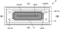
- FIG. 2B is a sectional view taken along line IIB-IIB in FIG. 2A. It is a cross-sectional top view which shows the evaporation source of 1st Embodiment in the case of film-forming a narrow base material.
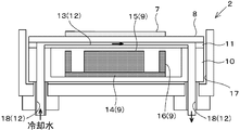
- FIG. 4B is a sectional view taken along line IVB-IVB in FIG. 4A. It is a cross-sectional top view which shows the evaporation source of 2nd Embodiment in the case of forming a base material with a narrow width.
- FIG. 5B is a cross-sectional view taken along line VB-VB in FIG. 5A. It is a cross-sectional top view which shows the structure of the evaporation source of 3rd Embodiment in the case of forming a base material with a narrow width
- FIG. 6B is a sectional view taken along line VIB-VIB in FIG. 6A. It is a cross-sectional top view which shows the structure of the conventional evaporation source in the case of film-forming a narrow base material.
- FIG. 1A shows the overall configuration of the film forming apparatus 1 according to the first embodiment of the present invention
- FIG. 1B shows a cross-sectional view of the evaporation source 2.
- the film forming apparatus 1 has a box-shaped vacuum chamber 3 whose inside can be evacuated.
- a vacuum pump (not shown) is connected to the vacuum chamber 3 via an exhaust pipe or the like, and the inside of the vacuum chamber 3 is brought into a vacuum or an extremely low pressure state by exhausting using the vacuum pump.
- a film formation drum 4 is provided that guides a base material W such as a film to be formed by winding it around the outer peripheral surface.
- an unwinding roll 5 for feeding the substrate W toward the film forming drum 4 and a winding roll for winding the substrate W formed on the film forming drum 4. 6 are provided.
- an evaporation source 2 is arranged inside the vacuum chamber 3 so as to face the substrate W wound around the film formation drum 4.
- the evaporation source 2 is supplied with power for plasma generation (DC (direct current), PulseDC (intermittent direct current), MF-AC (intermediate frequency range alternating current) or RF (high frequency)) from a plasma power source (not shown).
- DC direct current
- PulseDC intermittent direct current
- MF-AC intermediate frequency range alternating current
- RF radio frequency
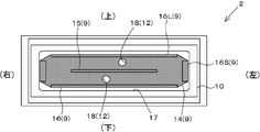
- the vertical direction of the paper surface of FIG. 2A is referred to as the front-rear direction when the film forming apparatus 1 is described.
- the left-right direction on the paper surface of FIG. 2A is referred to as the left-right direction when the film forming apparatus 1 is described.
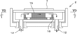
- the vertical direction of the paper surface of FIG. 2B is referred to as the vertical direction when the film forming apparatus 1 is described.
- the film forming apparatus 1 of the present invention will be described with reference to an example of an apparatus that forms a film using the magnetron sputtering method.
- the substrate W having a normal width is referred to as a “normal substrate”, and the substrate W having a width narrower than that of the normal substrate is referred to as a “narrow substrate”.
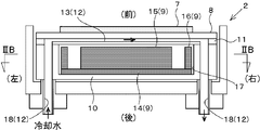
- FIG. 2A shows the configuration of the evaporation source 2 according to the first embodiment in the case where a substrate W (normal substrate) is formed.
- the evaporation source 2 includes a flat target material 7 formed of a film forming material, a backing plate 8 on which the target material 7 is attached, and a backing plate 8. And a magnet unit 9 for forming a magnetic field for magnetron discharge on the target material 7.
- the target material 7, the backing plate 8, the magnet unit 9, the cathode body 10, the water channel plate 11, and the cooling water flow channel 12 that constitute the evaporation source 2 of the first embodiment will be described.
- the width of the target material 7 is formed so as to be slightly wider than the normal base material, corresponding to the width of the normal base material described above. Further, the target material 7 is supplied with power for generating plasma from the above-described plasma power source through the cathode body 10 and is applied with a voltage capable of forming plasma on the surface.
- the backing plate 8 is usually formed in a plate shape with a metal, and copper that is excellent in both thermal conductivity and electrical conductivity is used, but SUS or the like can also be used.
- the surface of the backing plate 8 is smooth, and the backing plate 8 itself can be reused by attaching or peeling the target material 7 described above.
- the yoke 14 is formed in a plate shape with a magnetic material such as soft iron.
- a plate-shaped outer peripheral magnet 16 is provided on the outer edge of the yoke 14 so as to stand in a direction perpendicular to the surface of the yoke 14 (front-rear direction).
- the outer peripheral magnet 16 is composed of a combination of a plurality of plate magnets. Specifically, the outer peripheral magnet 16 extends along the long side direction (left and right direction) of the backing plate 8 and is arranged in parallel with each other, and a pair of long plate magnets 16L and the short side direction of the backing plate 8 A pair of short plate magnets 16 ⁇ / b> S that extend along (vertical direction) and are arranged in parallel to each other. All of these four plate magnets are arranged so that the end portions facing the target material 7 side (front side) have the same magnetic pole.
- the magnet unit 9 has a rectangular shape.
- the outer shape of the short plate magnet 16S disposed at the end of the outer magnet may be an arc shape, and the outer shape may be a racetrack shape.
- the cathode body 10 is a rectangular container that can accommodate the magnet unit 9 described above.
- a recess 17 is formed that opens toward the target material 7 side.
- the concave portion 17 has an inner dimension slightly larger than that of the magnet unit 9 in the vertical direction and the horizontal direction, and can accommodate the magnet unit 9 therein. Further, the depth of the recess 17, in other words, the inner dimension of the recess 17 in the front-rear direction is generally about the thickness of the magnet unit 9, but is a dimension that can accommodate the magnet unit 9 in combination with other members. And good.
- a cooling water supply / discharge pipe 18 for supplying cooling water is formed on the cathode body 10 on the outer side in the left-right direction with respect to the recess 17.
- the cooling water supply / drainage pipe 18 penetrates the cathode body 10 in the thickness direction (front-rear direction), and is provided at least two places (four places in the drawing) around the recess 17.
- the cooling water supply / discharge pipe 18 located on the left side of the magnet unit 9 is used as an introduction pipe for supplying the cooling water before cooling, and on the right side of the magnet unit 9.
- the cooling water supply / discharge pipe 18 positioned is used as a lead-out pipe for draining the cooled cooling water.
- the cooling water supply / discharge pipes 18 are provided at four locations, and the backing plate is cooled by two independent systems.
- the cooling water supply / discharge piping 18 may be provided at two places, and the flow of the cooling water may be controlled by the water channel accordingly.
- the film forming apparatus 1 of the first embodiment includes a water channel plate 11 disposed between the two members and separating (separating) them between the cathode body 10 and the backing plate 8.
- a channel groove 13 is formed on the surface of the water channel plate 11, and when the water channel plate 11 and the backing plate 8 are overlapped, the cooling water is circulated in a space formed by separating the magnet unit 9 and the backing plate 8. Possible cooling water flow paths 12 can be formed.
- the water channel plate 11 is disposed on the front side of the cathode body 10, closes the opening of the concave portion 17 of the cathode body 10, and functions as a lid of the concave portion 17.
- the size of the water channel plate 11 is substantially the same as the outer size of the cathode body 10 so that the entire front surface of the cathode body 10 can be covered.
- a cooling water channel 12 is formed for circulating the cooling water.
- the cooling water flow path 12 cools the cooling water supplied through the cooling water supply / discharge pipe 18 on the left side of the cathode body 10 while flowing through the inside of the water channel plate 11, and cools the cooling water on the right side of the cathode body 10.
- the cooling water supply / discharge pipe 18 is configured to discharge. Specifically, the cooling water flow path 12 extends from the connection point with the left cooling water supply / discharge pipe 18 toward the front side so as to penetrate the inside of the water channel plate 11 in the front-rear direction. Next, the cooling water channel 12 extending to the front surface of the water channel plate 11 changes its direction on the front surface of the water channel plate 11, and extends the gap between the backing plate 8 and the water channel plate 11 along the left-right direction. Finally, the cooling water channel 12 extends rearward so as to penetrate the inside of the water channel plate 11 in the front-rear direction, and discharges the cooling water from the right cooling water supply / discharge pipe 18 to the outside of the water channel plate 11. Yes.
- a portion along the front surface of the water channel plate 11 is a flow path groove 13 through which the cooling water flows along the left-right direction.
- the channel groove 13 is opened toward the front side, and cooling water can be directly brought into contact with the surface of the backing plate 8 superimposed on the water channel plate 11 so that the backing plate 8 can be efficiently cooled.
- the range where the flow channel 13 is formed on the surface of the water channel plate 11 covers the entire front surface of the magnet unit 9, and heat is input from the plasma to a position corresponding to the magnet unit 9.
- the target 7 to be received can be cooled via the backing plate 8.
- the cathode plate with the backing plate 8 and the water channel plate 11 fastened in advance is provided. It can be removed from the body 10.
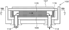
- the cooling water pipe 112 is formed so as to penetrate the inside of the magnet unit 109 in the front-rear direction, and is supplied through the cooling water pipe 112 on the left side.
- the cooled water is guided to a water channel that is formed between the central magnet 115 and the outer peripheral magnet 116 and faces in the left-right direction, and the target 107 is cooled via the backing plate 108, and is used for cooling.
- the cooling water is drained through the cooling water pipe 112 on the right side.
- the size of the magnet unit 109 is changed by this evaporation source, as shown in FIG. 6C, the position of the cooling water pipe 112 of the cathode body and the position of the cooling water pipe 112 of the magnet unit 109 are not matched. It becomes impossible to supply. Therefore, the size of the magnet unit cannot be changed with a conventional evaporation source.
- the cooling water flow path 12 is formed in the cathode body 10 and the water channel plate 11 that are fixed regardless of the width of the base material W. Even if the widths of the target material 7 and the magnet unit 9 are changed correspondingly, the position of the cooling water flow path 12 does not change, and the cooling does not become insufficient.
- the cooling water is circulated through the cooling water pipe 112.
- the target material 7 can be cooled via the backing plate 8, and stable film formation on a normal substrate is possible.
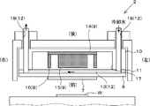
- FIG. 3B when a film is formed on a narrow base material having a width smaller than that of the normal base material, a short target material 7 and a magnet unit 9 corresponding to the base material width of the narrow base material Prepare. Even if it does so, it is possible to distribute
- the evaporation source 2 is configured without replacing the entire evaporation source 2. By replacing only the magnet unit 9 and the target material 7, it is possible to perform film formation without waste corresponding to the size change of the substrate W.
- the water channel plate 11 is provided between the backing plate 8 and the cathode body 10 described above, the water channel plate 11 can be easily attached to and detached from the cathode body 10 together with the backing plate 8, and the number of bolts can be reduced. A watertight seal structure can also be performed.
- the cooling water flow path 12 flows through the inside of the cathode body 10 and the water channel plate 11, the cooling water does not touch the magnet unit 9. Therefore, it is possible to improve the durability of the magnet unit 9 that is vulnerable to water, and to perform stable film formation over a long period of time.
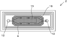
- the cooling water supply / discharge pipes 18 of the cooling water passage 12 for supplying the cooling water to the back surface of the backing plate 8 are provided on both sides of the magnet unit 9. It is not provided in the cathode body 10 but is provided so as to penetrate the center of the magnet unit 9.
- two cooling water supply / discharge pipes 18 for supplying or discharging the cooling water are arranged in the vertical direction at the approximate center in the left-right direction of the cathode body 10.
- one cooling water supply / discharge pipe 18 (the cooling water supply / discharge pipe 18 below the cathode body 10) serves as a cooling water introduction path.
- the supply / discharge pipe 18 (the cooling water supply / discharge pipe 18 on the upper side of the cathode body 10) serves as a cooling water outlet path.
- Each of these cooling water supply / discharge pipes 18 is formed so as to penetrate the magnet unit 9 and the water channel plate 11 in the front-rear direction, and the cooling water is provided in the flow channel 13 formed on the front surface of the water channel plate 11. Can be distributed.
- the channel groove 13 formed in the water channel plate 11 of the second embodiment is formed so as to surround the central magnet 15 and is supplied from one cooling water supply / discharge pipe 18.
- the cooling water is circulated from the lower side to the upper side so as to circulate around the central magnet 15, and the cooling water can be concentrated and drained from the other cooling water flow path 12.
- the cooling water supply / discharge pipe 18 is not formed in the wall of the cathode body 10, and is provided at the center of the cathode body 10, so that the width of the cathode body 10 is increased. Is more compact than the first embodiment.
- the magnet unit 9 is installed within a range in which the central cooling water flow path 12 is not changed. It can be shrunk in the left-right direction, and the size and arrangement of the magnet unit 9 can be freely changed. By making the target 7 into a shape corresponding to the magnet unit 9, it is possible to realize an optimum apparatus configuration for both a normal width substrate and a narrow width substrate.
- the interior of the magnet unit 9 is moved back and forth in the same manner as the cooling water pipe 112 of the conventional evaporation source 102 shown in FIGS. 6A and 6B.
- a pair of cooling water pipes 12 is formed so as to penetrate in the direction.
- the film forming apparatus 1 guides the cooling water supplied through the cooling water pipe 12 on the left side to a water channel that is formed between the central magnet 5 and the outer peripheral magnet 6 and faces in the left-right direction, via the backing plate 8.
- the target 7 is cooled, and the cooling water used for cooling is drained through the cooling water pipe 12 on the right side.
- the difference between the evaporation source 2 according to the third embodiment and the conventional evaporation source 102 is that the height of the short side of the outer peripheral magnet 16 of the magnet unit 9 is designed to be lower than the long side. Therefore, as shown in FIG. 5C, when the magnet unit 9 having a short length is attached to the cathode body 10, it is possible to secure a flow path of the cooling water as shown in FIGS. 5C and 5D. . For this reason, as shown in FIG. 5C, by attaching the short target material 7, the film forming process can be economically performed on the narrow base material W as in the first embodiment and the second embodiment.
- the film forming apparatus 1 As described above, by using the film forming apparatus 1 according to each embodiment of the present invention, only the magnet unit 9 and the target material 7 constituting the evaporation source 2 are replaced without replacing the evaporation source 2 itself.
- the film can be stably formed in response to the size change of the substrate W.
- the present invention is not limited to the above embodiments, and the shape, structure, material, combination, and the like of each member can be appropriately changed without departing from the essence of the invention. Further, in the embodiment disclosed this time, matters that are not explicitly disclosed, for example, operating conditions and operating conditions, various parameters, dimensions, weights, volumes, and the like of a component deviate from a range that a person skilled in the art normally performs. However, matters that can be easily assumed by those skilled in the art are employed.
- a film forming apparatus and a film forming method are provided.
- a film forming apparatus provided by the present invention is a film forming apparatus that forms a film on a surface of a substrate to be transported using an evaporation source facing the substrate, and the evaporation source is formed of a film forming material.
- a cathode body that houses the unit, and a cooling water passage that is a space formed by separating the magnet unit and the backing plate and in which the cooling water can flow.
- the magnet unit having a short size can be deployed correspondingly, and corresponds to the width of the deployed magnet unit. Short target material is deployed.
- the film forming method of the present invention when the film is formed on the surface of the base material using the above-described film forming apparatus, the film is formed on the surface of the narrow base material that is narrower than the base material.
- a short-sized magnet unit is provided, and a target material having a short size corresponding to the width of the provided magnet unit is provided to perform film formation.
- the film forming apparatus and the film forming method of the present invention it is possible to form a film on substrates having different widths by replacing only the magnet unit and the target material constituting the evaporation source without replacing the evaporation source itself. Will be able to do.
- the magnet unit is formed in a rectangular shape when viewed from the front, and the cooling water flow path is formed outside one end in the longitudinal direction of the magnet unit, and between the water channel plate and the backing plate. It is preferable to have an introduction path through which the cooling water flows in and a lead-out path that is formed outside the other end in the longitudinal direction of the magnet unit and leads the cooling water to the outside.
- the magnet unit is formed in a rectangular shape when viewed from the front, and the cooling water flow path is formed in the vicinity of the central portion in the longitudinal direction of the magnet unit, and between the water channel plate and the backing plate. It is preferable to have an introduction path through which cooling water flows and a lead-out path that is formed in the vicinity of the central portion in the longitudinal direction of the magnet unit and guides the cooling water to the outside.
- the magnet unit is formed in a rectangular shape when viewed from the front, and at least the short side portion of the outer peripheral magnetic pole is configured to be low, and the cooling water passage is mounted with a normal-sized magnet unit.
- the cooling water is introduced or derived from the space between the outer magnetic pole and the central magnetic pole in the vicinity of the shorter side of the outer magnetic pole, and when installing a short magnet unit, the shorter side of the magnet unit Cooling water may be introduced or derived from the outside of the section.
Landscapes
- Chemical & Material Sciences (AREA)
- Engineering & Computer Science (AREA)
- Chemical Kinetics & Catalysis (AREA)
- Materials Engineering (AREA)
- Mechanical Engineering (AREA)
- Metallurgy (AREA)
- Organic Chemistry (AREA)
- Physics & Mathematics (AREA)
- Plasma & Fusion (AREA)
- Analytical Chemistry (AREA)
- Physical Vapour Deposition (AREA)
Abstract
Description
Claims (5)
- 基材に対向する蒸発源を用いて、搬送される基材の表面に成膜を行う成膜装置であって、
前記蒸発源は、成膜物質で形成された平板状のターゲット材と、前記ターゲット材が表面に取り付けられたバッキングプレートと、前記バッキングプレートの裏側に配備されて、ターゲット材表面近傍にマグネトロン放電のための磁場を形成する磁石ユニットと、前記磁石ユニットを収納するカソードボディーと、前記磁石ユニットとバッキングプレートとが離間してなる空間であって且つ当該空間には冷却水が流通可能となっている冷却水流路と、を有しており、
前記磁石ユニットとして、前記基材よりも狭幅とされた狭幅基材に対応して短尺のサイズの磁石ユニットが配備可能とされ、前記ターゲット材として、配備された磁石ユニットの幅に対応して短尺のサイズのターゲット材が配備されている、成膜装置。 - 前記磁石ユニットは、前記カソードボディーの正面視で長方形の空間に収納されており、前記冷却水流路は、前記カソードボディーの長手方向の一方端に形成されて前記バッキングプレート背面の冷却水流路へのとの間に冷却水の導入路と、前記カソードボディーの長手方向の他方端に形成されて冷却水の導出路と、を有している、請求項1に記載の成膜装置。
- 前記磁石ユニットは、正面視で長方形に形成されており、前記冷却水流路は、前記磁石ユニットの長手方向の中央部に形成されて前記水路板とバッキングプレートとの間に冷却水を流入させる導入路と、前記磁石ユニットの長手方向の中央部に形成されて冷却水を外部に導出する導出路と、を有している、請求項1に記載の成膜装置。
- 前記磁石ユニットは、正面視で長方形に形成されると共に、少なくとも外周磁極の短辺部の高さが低く構成されており、前記冷却水流路は、通常尺の磁石ユニットを搭載する場合には、冷却水は外周磁極の短辺部付近の外周磁極と中央磁極の間の空間から導入乃至は導出され、短尺の磁石ユニットを搭載する場合には、前記磁石ユニットの前記短辺部の外側から冷却水が導入乃至は導出する、請求項1に記載の成膜装置。
- 請求項1に記載された成膜装置を用いて、基材の表面に成膜を行う方法であって、
前記成膜装置に適合する基材よりも狭幅とされた狭幅基材の表面に成膜を行う場合には、短尺のサイズの磁石ユニットを配備し、配備した磁石ユニットの幅に対応して短尺のサイズのターゲット材を配備して成膜を実施する、成膜方法。
Priority Applications (4)
| Application Number | Priority Date | Filing Date | Title |
|---|---|---|---|
| CN201480027855.1A CN105189810B (zh) | 2013-05-15 | 2014-03-31 | 成膜装置及成膜方法 |
| KR1020157032260A KR20150140384A (ko) | 2013-05-15 | 2014-03-31 | 성막 장치 및 성막 방법 |
| US14/782,711 US9758857B2 (en) | 2013-05-15 | 2014-03-31 | Deposition device and deposition method |
| DE112014002431.7T DE112014002431B4 (de) | 2013-05-15 | 2014-03-31 | Abscheidungsvorrichtung und Abscheidungsverfahren |
Applications Claiming Priority (2)
| Application Number | Priority Date | Filing Date | Title |
|---|---|---|---|
| JP2013103269A JP5950866B2 (ja) | 2013-05-15 | 2013-05-15 | 成膜装置及び成膜方法 |
| JP2013-103269 | 2013-05-15 |
Publications (1)
| Publication Number | Publication Date |
|---|---|
| WO2014184997A1 true WO2014184997A1 (ja) | 2014-11-20 |
Family
ID=51897991
Family Applications (1)
| Application Number | Title | Priority Date | Filing Date |
|---|---|---|---|
| PCT/JP2014/001875 Ceased WO2014184997A1 (ja) | 2013-05-15 | 2014-03-31 | 成膜装置及び成膜方法 |
Country Status (6)
| Country | Link |
|---|---|
| US (1) | US9758857B2 (ja) |
| JP (1) | JP5950866B2 (ja) |
| KR (1) | KR20150140384A (ja) |
| CN (1) | CN105189810B (ja) |
| DE (1) | DE112014002431B4 (ja) |
| WO (1) | WO2014184997A1 (ja) |
Families Citing this family (4)
| Publication number | Priority date | Publication date | Assignee | Title |
|---|---|---|---|---|
| US9321833B2 (en) * | 2011-04-04 | 2016-04-26 | The Trustees Of Dartmouth College | Methods of therapy with anti-CD154 antibodies having impaired FcR binding and/or complement binding properties |
| WO2017220649A1 (en) * | 2016-06-23 | 2017-12-28 | Harman Becker Automotive Systems Gmbh | Magnet assembly for a loudspeaker and loudspeaker with such a magnet assembly |
| CN109440070A (zh) * | 2018-11-19 | 2019-03-08 | 东部超导科技(苏州)有限公司 | 基于ibad纳米涂层设备的溅射靶冷却装置 |
| CN112144034B (zh) * | 2019-06-27 | 2022-12-30 | 昆山世高新材料科技有限公司 | 一种冷却背板 |
Citations (7)
| Publication number | Priority date | Publication date | Assignee | Title |
|---|---|---|---|---|
| JPH0693442A (ja) * | 1992-09-11 | 1994-04-05 | Ulvac Japan Ltd | マグネトロン・スパッタカソード |
| JPH09125245A (ja) * | 1995-10-31 | 1997-05-13 | Sony Corp | スパッタリング装置 |
| JP2001509209A (ja) * | 1996-12-10 | 2001-07-10 | ルシェルシュ エ ディヴェロップマン デュ グループ コッケリール サンブル | 陰極スパッタリングにより基板上に膜を形成する方法及び装置 |
| JP2003193227A (ja) * | 2001-11-20 | 2003-07-09 | Unaxis Balzer Ag | 真空処理プロセスのためのソース |
| JP2010132994A (ja) * | 2008-12-08 | 2010-06-17 | Canon Anelva Corp | スパッタリング装置 |
| JP2011117019A (ja) * | 2009-12-01 | 2011-06-16 | Showa Denko Kk | マグネトロンスパッタ装置、インライン式成膜装置、磁気記録媒体の製造方法、磁気記録再生装置 |
| JP2013014803A (ja) * | 2011-07-04 | 2013-01-24 | Iza Corp | 磁石ユニット、磁界発生装置及びマグネトロンスパッタ装置 |
Family Cites Families (8)
| Publication number | Priority date | Publication date | Assignee | Title |
|---|---|---|---|---|
| JPH05311430A (ja) | 1992-05-11 | 1993-11-22 | Fuji Electric Co Ltd | マグネトロンスパッタリングカソード |
| US6207026B1 (en) * | 1999-10-13 | 2001-03-27 | Applied Materials, Inc. | Magnetron with cooling system for substrate processing system |
| JP2002231984A (ja) * | 2001-02-01 | 2002-08-16 | Canon Inc | 透明導電膜の成膜方法、半導体層の欠陥領域補償方法、光起電力素子、及びその製造方法 |
| DE10323258A1 (de) | 2003-05-23 | 2004-12-23 | Applied Films Gmbh & Co. Kg | Magnetron-Sputter-Kathode |
| EP1873809A1 (en) * | 2006-06-26 | 2008-01-02 | M2 Engineering AB (publ) | Sputtering device |
| JP4526582B2 (ja) | 2007-11-30 | 2010-08-18 | パナソニック株式会社 | スパッタリング装置およびスパッタリング方法 |
| JP2010284693A (ja) * | 2009-06-12 | 2010-12-24 | Mitsubishi Heavy Ind Ltd | 冷却板およびその製造方法 |
| TWI515320B (zh) * | 2012-04-26 | 2016-01-01 | 因特瓦克公司 | 供物理氣相沈積製程使用之窄型濺鍍源 |
-
2013
- 2013-05-15 JP JP2013103269A patent/JP5950866B2/ja not_active Expired - Fee Related
-
2014
- 2014-03-31 WO PCT/JP2014/001875 patent/WO2014184997A1/ja not_active Ceased
- 2014-03-31 US US14/782,711 patent/US9758857B2/en not_active Expired - Fee Related
- 2014-03-31 DE DE112014002431.7T patent/DE112014002431B4/de active Active
- 2014-03-31 CN CN201480027855.1A patent/CN105189810B/zh not_active Expired - Fee Related
- 2014-03-31 KR KR1020157032260A patent/KR20150140384A/ko not_active Ceased
Patent Citations (7)
| Publication number | Priority date | Publication date | Assignee | Title |
|---|---|---|---|---|
| JPH0693442A (ja) * | 1992-09-11 | 1994-04-05 | Ulvac Japan Ltd | マグネトロン・スパッタカソード |
| JPH09125245A (ja) * | 1995-10-31 | 1997-05-13 | Sony Corp | スパッタリング装置 |
| JP2001509209A (ja) * | 1996-12-10 | 2001-07-10 | ルシェルシュ エ ディヴェロップマン デュ グループ コッケリール サンブル | 陰極スパッタリングにより基板上に膜を形成する方法及び装置 |
| JP2003193227A (ja) * | 2001-11-20 | 2003-07-09 | Unaxis Balzer Ag | 真空処理プロセスのためのソース |
| JP2010132994A (ja) * | 2008-12-08 | 2010-06-17 | Canon Anelva Corp | スパッタリング装置 |
| JP2011117019A (ja) * | 2009-12-01 | 2011-06-16 | Showa Denko Kk | マグネトロンスパッタ装置、インライン式成膜装置、磁気記録媒体の製造方法、磁気記録再生装置 |
| JP2013014803A (ja) * | 2011-07-04 | 2013-01-24 | Iza Corp | 磁石ユニット、磁界発生装置及びマグネトロンスパッタ装置 |
Also Published As
| Publication number | Publication date |
|---|---|
| CN105189810B (zh) | 2017-09-29 |
| JP2014224284A (ja) | 2014-12-04 |
| US20160047032A1 (en) | 2016-02-18 |
| JP5950866B2 (ja) | 2016-07-13 |
| DE112014002431B4 (de) | 2023-02-09 |
| DE112014002431T5 (de) | 2016-02-18 |
| US9758857B2 (en) | 2017-09-12 |
| CN105189810A (zh) | 2015-12-23 |
| KR20150140384A (ko) | 2015-12-15 |
Similar Documents
| Publication | Publication Date | Title |
|---|---|---|
| CN101979705B (zh) | 改进的pvd靶 | |
| US9096927B2 (en) | Cooling ring for physical vapor deposition chamber target | |
| JP6360882B2 (ja) | フレキシブル基板のための堆積プラットフォーム及びその操作方法 | |
| US20150136585A1 (en) | Method for sputtering for processes with a pre-stabilized plasma | |
| US6881311B2 (en) | Facing-targets-type sputtering apparatus | |
| JP5950866B2 (ja) | 成膜装置及び成膜方法 | |
| JP5527894B2 (ja) | スパッタ装置 | |
| US8715471B2 (en) | Magnetron sputter cathode | |
| US9368331B2 (en) | Sputtering apparatus | |
| CN104204270A (zh) | 真空成膜装置及真空成膜方法 | |
| CN104532199A (zh) | 一种中频磁控溅射镀膜用阴极 | |
| JP2014162931A (ja) | 成膜方法及び成膜装置 | |
| SG190912A1 (en) | Plasma cvd apparatus, magnetic recording medium and method for manufacturing the same | |
| EP2811508B1 (en) | Gas configuration for magnetron deposition systems | |
| EP3073808B1 (en) | Plasma cvd device and method for manufacturing a substrate with a thin film | |
| US20160099135A1 (en) | Rectangular Hollow Sputter Source and Method of use Thereof | |
| JP4230564B2 (ja) | スパッタリング装置 | |
| JP5095087B2 (ja) | 成膜装置及び成膜方法 | |
| JP2011074480A (ja) | スパッタリング装置 | |
| KR20150034475A (ko) | 스퍼터링 장치 | |
| JP2008280550A (ja) | 対向ターゲットスパッタ装置及び方法 | |
| JP2009209439A (ja) | 真空成膜装置 | |
| SE537187C2 (sv) | Magnetronplasmaapparat förstärkt genom hålkatodplasma |
Legal Events
| Date | Code | Title | Description |
|---|---|---|---|
| WWE | Wipo information: entry into national phase |
Ref document number: 201480027855.1 Country of ref document: CN |
|
| 121 | Ep: the epo has been informed by wipo that ep was designated in this application |
Ref document number: 14798639 Country of ref document: EP Kind code of ref document: A1 |
|
| WWE | Wipo information: entry into national phase |
Ref document number: 14782711 Country of ref document: US |
|
| ENP | Entry into the national phase |
Ref document number: 20157032260 Country of ref document: KR Kind code of ref document: A |
|
| WWE | Wipo information: entry into national phase |
Ref document number: 112014002431 Country of ref document: DE |
|
| 122 | Ep: pct application non-entry in european phase |
Ref document number: 14798639 Country of ref document: EP Kind code of ref document: A1 |