WO2014184883A1 - Air conditioning system - Google Patents
Air conditioning system Download PDFInfo
- Publication number
- WO2014184883A1 WO2014184883A1 PCT/JP2013/063466 JP2013063466W WO2014184883A1 WO 2014184883 A1 WO2014184883 A1 WO 2014184883A1 JP 2013063466 W JP2013063466 W JP 2013063466W WO 2014184883 A1 WO2014184883 A1 WO 2014184883A1
- Authority
- WO
- WIPO (PCT)
- Prior art keywords
- temperature
- value
- indoor
- evaporation temperature
- heat exchanger
- Prior art date
Links
Images


Classifications
-
- F—MECHANICAL ENGINEERING; LIGHTING; HEATING; WEAPONS; BLASTING
- F24—HEATING; RANGES; VENTILATING
- F24F—AIR-CONDITIONING; AIR-HUMIDIFICATION; VENTILATION; USE OF AIR CURRENTS FOR SCREENING
- F24F3/00—Air-conditioning systems in which conditioned primary air is supplied from one or more central stations to distributing units in the rooms or spaces where it may receive secondary treatment; Apparatus specially designed for such systems
- F24F3/06—Air-conditioning systems in which conditioned primary air is supplied from one or more central stations to distributing units in the rooms or spaces where it may receive secondary treatment; Apparatus specially designed for such systems characterised by the arrangements for the supply of heat-exchange fluid for the subsequent treatment of primary air in the room units
-
- F—MECHANICAL ENGINEERING; LIGHTING; HEATING; WEAPONS; BLASTING
- F24—HEATING; RANGES; VENTILATING
- F24F—AIR-CONDITIONING; AIR-HUMIDIFICATION; VENTILATION; USE OF AIR CURRENTS FOR SCREENING
- F24F1/00—Room units for air-conditioning, e.g. separate or self-contained units or units receiving primary air from a central station
- F24F1/0003—Room units for air-conditioning, e.g. separate or self-contained units or units receiving primary air from a central station characterised by a split arrangement, wherein parts of the air-conditioning system, e.g. evaporator and condenser, are in separately located units
-
- F—MECHANICAL ENGINEERING; LIGHTING; HEATING; WEAPONS; BLASTING
- F24—HEATING; RANGES; VENTILATING
- F24F—AIR-CONDITIONING; AIR-HUMIDIFICATION; VENTILATION; USE OF AIR CURRENTS FOR SCREENING
- F24F1/00—Room units for air-conditioning, e.g. separate or self-contained units or units receiving primary air from a central station
- F24F1/0007—Indoor units, e.g. fan coil units
- F24F1/0035—Indoor units, e.g. fan coil units characterised by introduction of outside air to the room
-
- F—MECHANICAL ENGINEERING; LIGHTING; HEATING; WEAPONS; BLASTING
- F24—HEATING; RANGES; VENTILATING
- F24F—AIR-CONDITIONING; AIR-HUMIDIFICATION; VENTILATION; USE OF AIR CURRENTS FOR SCREENING
- F24F11/00—Control or safety arrangements
- F24F11/0001—Control or safety arrangements for ventilation
-
- F—MECHANICAL ENGINEERING; LIGHTING; HEATING; WEAPONS; BLASTING
- F24—HEATING; RANGES; VENTILATING
- F24F—AIR-CONDITIONING; AIR-HUMIDIFICATION; VENTILATION; USE OF AIR CURRENTS FOR SCREENING
- F24F11/00—Control or safety arrangements
- F24F11/0008—Control or safety arrangements for air-humidification
-
- F—MECHANICAL ENGINEERING; LIGHTING; HEATING; WEAPONS; BLASTING
- F24—HEATING; RANGES; VENTILATING
- F24F—AIR-CONDITIONING; AIR-HUMIDIFICATION; VENTILATION; USE OF AIR CURRENTS FOR SCREENING
- F24F11/00—Control or safety arrangements
- F24F11/89—Arrangement or mounting of control or safety devices
-
- F—MECHANICAL ENGINEERING; LIGHTING; HEATING; WEAPONS; BLASTING
- F24—HEATING; RANGES; VENTILATING
- F24F—AIR-CONDITIONING; AIR-HUMIDIFICATION; VENTILATION; USE OF AIR CURRENTS FOR SCREENING
- F24F12/00—Use of energy recovery systems in air conditioning, ventilation or screening
- F24F12/001—Use of energy recovery systems in air conditioning, ventilation or screening with heat-exchange between supplied and exhausted air
- F24F12/006—Use of energy recovery systems in air conditioning, ventilation or screening with heat-exchange between supplied and exhausted air using an air-to-air heat exchanger
-
- F—MECHANICAL ENGINEERING; LIGHTING; HEATING; WEAPONS; BLASTING
- F24—HEATING; RANGES; VENTILATING
- F24F—AIR-CONDITIONING; AIR-HUMIDIFICATION; VENTILATION; USE OF AIR CURRENTS FOR SCREENING
- F24F3/00—Air-conditioning systems in which conditioned primary air is supplied from one or more central stations to distributing units in the rooms or spaces where it may receive secondary treatment; Apparatus specially designed for such systems
- F24F3/06—Air-conditioning systems in which conditioned primary air is supplied from one or more central stations to distributing units in the rooms or spaces where it may receive secondary treatment; Apparatus specially designed for such systems characterised by the arrangements for the supply of heat-exchange fluid for the subsequent treatment of primary air in the room units
- F24F3/065—Air-conditioning systems in which conditioned primary air is supplied from one or more central stations to distributing units in the rooms or spaces where it may receive secondary treatment; Apparatus specially designed for such systems characterised by the arrangements for the supply of heat-exchange fluid for the subsequent treatment of primary air in the room units with a plurality of evaporators or condensers
-
- F—MECHANICAL ENGINEERING; LIGHTING; HEATING; WEAPONS; BLASTING
- F24—HEATING; RANGES; VENTILATING
- F24F—AIR-CONDITIONING; AIR-HUMIDIFICATION; VENTILATION; USE OF AIR CURRENTS FOR SCREENING
- F24F3/00—Air-conditioning systems in which conditioned primary air is supplied from one or more central stations to distributing units in the rooms or spaces where it may receive secondary treatment; Apparatus specially designed for such systems
- F24F3/12—Air-conditioning systems in which conditioned primary air is supplied from one or more central stations to distributing units in the rooms or spaces where it may receive secondary treatment; Apparatus specially designed for such systems characterised by the treatment of the air otherwise than by heating and cooling
- F24F3/14—Air-conditioning systems in which conditioned primary air is supplied from one or more central stations to distributing units in the rooms or spaces where it may receive secondary treatment; Apparatus specially designed for such systems characterised by the treatment of the air otherwise than by heating and cooling by humidification; by dehumidification
-
- F—MECHANICAL ENGINEERING; LIGHTING; HEATING; WEAPONS; BLASTING
- F24—HEATING; RANGES; VENTILATING
- F24F—AIR-CONDITIONING; AIR-HUMIDIFICATION; VENTILATION; USE OF AIR CURRENTS FOR SCREENING
- F24F7/00—Ventilation
- F24F7/04—Ventilation with ducting systems, e.g. by double walls; with natural circulation
- F24F7/06—Ventilation with ducting systems, e.g. by double walls; with natural circulation with forced air circulation, e.g. by fan positioning of a ventilator in or against a conduit
- F24F7/08—Ventilation with ducting systems, e.g. by double walls; with natural circulation with forced air circulation, e.g. by fan positioning of a ventilator in or against a conduit with separate ducts for supplied and exhausted air with provisions for reversal of the input and output systems
-
- Y—GENERAL TAGGING OF NEW TECHNOLOGICAL DEVELOPMENTS; GENERAL TAGGING OF CROSS-SECTIONAL TECHNOLOGIES SPANNING OVER SEVERAL SECTIONS OF THE IPC; TECHNICAL SUBJECTS COVERED BY FORMER USPC CROSS-REFERENCE ART COLLECTIONS [XRACs] AND DIGESTS
- Y02—TECHNOLOGIES OR APPLICATIONS FOR MITIGATION OR ADAPTATION AGAINST CLIMATE CHANGE
- Y02B—CLIMATE CHANGE MITIGATION TECHNOLOGIES RELATED TO BUILDINGS, e.g. HOUSING, HOUSE APPLIANCES OR RELATED END-USER APPLICATIONS
- Y02B30/00—Energy efficient heating, ventilation or air conditioning [HVAC]
- Y02B30/56—Heat recovery units
Definitions
- the present invention relates to an air conditioning harmony system including an air conditioner and a ventilator.
- the ventilator performs an operation of replacing indoor air with fresh outdoor air, and when cooling, when the enthalpy of air introduced from the outside air is high It becomes a cooling load (outside air load).
- Other heat loads include an indoor load generated indoors and a housing load entering from a building wall.
- the latent heat load has been processed with the refrigerant evaporation temperature of the indoor heat exchanger of the air conditioner kept constant at a low temperature.
- the operation in which the evaporation temperature is kept constant at a low temperature and the latent heat load is processed there is a problem that the operation efficiency is lowered.
- the operation efficiency is improved, but there is a problem that the amount of latent heat treatment is insufficient, the indoor humidity is increased, and the comfort is lowered.
- the ventilator and the air conditioner that perform outside air processing are controlled independently, and the evaporation temperature of the indoor heat exchanger of the air conditioner is controlled to be equal to or higher than the dew point temperature of the indoor air to mainly process the sensible heat load.
- a latent sensible and separated air conditioning system that sets an evaporation temperature that secures a necessary dehumidification amount with a ventilator that performs outside air processing and mainly processes a latent heat load (for example, Patent Document 1).
- the sensible heat is controlled by controlling the refrigeration cycle in each of the air conditioner and the ventilator and adjusting the evaporation temperature of each evaporator.
- the load and latent heat load are shared, the evaporating temperature of the ventilator is set based on the required dehumidification amount, and the evaporating temperature of the indoor heat exchanger of the air conditioner is set above the dew point temperature. It was a single setting method. For this reason, there has been a problem that it is impossible to set an appropriate evaporating temperature in consideration of the outside air temperature humidity condition, the indoor temperature humidity condition, and the like in the respective evaporators of the air conditioner and the ventilator.
- the present invention has been made in order to solve the conventional method for setting an appropriate evaporation temperature of an evaporator, and considers outdoor air load, and comfort due to insufficient amount of latent heat treatment (insufficient dehumidification). It aims at providing the air conditioning system which implement
- An air conditioning system has a refrigerant system composed of an outdoor unit in which refrigerant circulates, an indoor unit, and a ventilator, and the refrigerant system includes a compressor, an outdoor heat exchanger, a first expansion valve, It has an indoor heat exchanger, a second expansion valve, and a ventilator cooler, and the indoor unit has the first expansion valve and the indoor heat exchanger, and circulates indoor air while adjusting the temperature.
- the ventilator has the second expansion valve and the ventilator cooler, and is configured to exchange indoor air and outdoor air, and to cool and dehumidify the outdoor air with the ventilator cooler,
- the outdoor unit, the indoor unit, and the ventilator are connected by a refrigerant pipe and have means for detecting the temperature and humidity of outdoor air, and the indoor heat exchanger and the ventilator are cooled according to the outdoor air temperature and humidity.
- the maximum and minimum evaporating temperature setpoints The evaporating temperature set values of the indoor heat exchanger and the ventilator cooler are set between the maximum evaporating temperature set value and the minimum evaporating temperature set value, and the indoor heat exchanger and the ventilator cooling
- the evaporation temperature of the vessel is controlled so as to become the evaporation temperature set value.
- the evaporating temperature set values of the indoor heat exchanger and the ventilator cooler are set in a range between the maximum evaporating temperature set value and the minimum evaporating temperature set value that are changed based on the outside air temperature and humidity conditions. Therefore, it is possible to set the evaporating temperature setting value with a predetermined control width assuming the sensible heat load and the latent heat load from the outside air temperature and humidity conditions. Therefore, it becomes easy to follow load fluctuations, realize latent heat treatment and sensible heat treatment at an appropriate evaporation temperature, and ensure energy saving while maintaining comfort.
- FIG. 1 It is a schematic diagram of an air-conditioning system in the present invention. It is a refrigerant circuit figure at the time of air_conditionaing
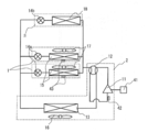
- FIG. 1 is a schematic diagram of an air conditioning system according to the first embodiment.
- the air conditioning system 100 one or a plurality of indoor units 1 and one or a plurality of ventilators 3 are connected by an outdoor unit 2 and a refrigerant pipe 104.
- the indoor unit 1, the outdoor unit 2, and the ventilator 3 are connected to the centralized controller 102 through the transmission line 103.
- the centralized controller 102 is provided with target temperature / humidity setting means 44 (not shown).
- FIG. 2 is a refrigerant circuit diagram of the air-conditioning system according to Embodiment 1.
- the refrigerant system circuit includes a compressor 11, a four-way valve 12, an outdoor heat exchanger 13, a first expansion valve 14a, an indoor heat exchanger 15, a second expansion valve 14b, and a ventilator cooler 18.
- the indoor unit 1 includes a first expansion valve 14a, an indoor heat exchanger 15, and an indoor heat exchanger blower 17, and one or more indoor units 1 are installed.
- the ventilator 3 includes a second expansion valve 14b and a ventilator cooler 18, and one or a plurality of ventilators 3 are installed.
- FIG. 3 is a schematic configuration diagram of the ventilation device 3 of the air-conditioning system according to the first embodiment.
- the outdoor air (OA) after the total heat exchange is supplied to the room as supply air (SA), and the indoor air (RA) after the total heat exchange is exhausted to the outside as exhaust air (EA).
- SA supply air
- EA exhaust air
- FIG. 4 is a refrigerant circuit diagram of the air-conditioning system according to Embodiment 1. As shown in FIG. 4, compressor frequency adjusting means 41 and evaporation temperature detecting means 42 are provided, and each indoor unit 1 is provided with suction temperature and humidity detecting means 43.
- FIG. 5 is a diagram showing the evaporating temperature set value Te of the indoor heat exchanger 15 or the ventilator cooler 18 of the ventilator 3 in the first embodiment.
- the vertical axis represents the evaporation temperature set value Te of the indoor heat exchanger 15 or the ventilator cooler 18 of the ventilator 3, and the horizontal axis represents the target temperature / humidity setting means from the indoor temperature Ta detected by the suction temperature / humidity detection means 43.
- ⁇ T which is a temperature difference obtained by subtracting the indoor target temperature Ta_tgt set in 44.
- Te_max represents the maximum evaporation temperature that is the maximum value of the evaporation temperature set value Te
- Te_min represents the minimum evaporation temperature that is the minimum value of the evaporation temperature set value Te.
- the evaporation temperature of the indoor heat exchanger 15 or the ventilator cooler 18 is determined between the maximum evaporation temperature Te_max and the minimum evaporation temperature Te_min according to ⁇ T which is a temperature difference obtained by subtracting the indoor target temperature Ta_tgt from the indoor temperature Ta. It is adjusted by changing the operating frequency of the compressor 11 by the compressor frequency adjusting means 41 and adjusting the opening degree of the expansion valve 14 so that the evaporation temperature set value Te is obtained.
- FIG. 6 shows a setting range of the evaporation temperature set value Te for one indoor unit system and three ventilator systems in the first embodiment.
- the maximum evaporation temperature Te_max and the minimum evaporation temperature Te_min of the indoor heat exchanger 15 of the indoor unit system 1 and the ventilator cooler 18 of the ventilation system 3 are ET_max.
- the maximum evaporating temperature Te_max and the minimum evaporating temperature Te_min have two patterns of values of Hi level with a high evaporating temperature and Lo level with a low evaporating temperature in the indoor heat exchanger 15 and the ventilator cooler 18, respectively.
- the maximum evaporation temperature when the indoor heat exchanger 15 is at a high evaporation level Hi level is ETi_hi_max
- the minimum evaporation temperature is ETi_hi_min
- the maximum evaporation temperature when the evaporation temperature is low Lo is ETi_lo_max
- the minimum evaporation temperature is ETi_lo_min.
- the maximum evaporation temperature when the ventilator cooler 18 is at a high evaporation level Hi level is ETv_hi_max
- the minimum evaporation temperature is ETv_hi_min
- the maximum evaporation temperature when the evaporation temperature is low Lo level is ETv_lo_max
- the minimum evaporation temperature is ETv_lo_min.
- ETi_hi_max 14 ° C.
- ETv_hi_max 12 ° C.
- ETi_hi_min 9 ° C.
- ETv_hi_min 7 ° C.
- ETi_lo_max 9 ° C.
- ETv_lo_max 7 ° C.
- ETi_lo_min 2 ° C.
- ETv_lo_min 0 ° C.
- the sensible heat load and the latent heat load can be more appropriately processed by setting the maximum evaporation temperature ET_max and the minimum evaporation temperature ET_min of the indoor heat exchanger 15 and the ventilator cooler 18 to optimum values, respectively. It becomes possible.
- the switching between the Hi level and the Lo level of the evaporation temperature is determined by the outside air temperature and humidity conditions so that one indoor unit system is a sensible heat treatment main body, and three ventilation devices are a sensible heat treatment + latent heat treatment.
- the detection value of the OA temperature / humidity detection means 31 of the ventilator 3 is used as the outside air temperature humidity.
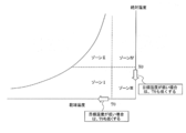
- FIG. 7 is an air diagram in which the conditions of the outside air sucked into the ventilation device 3 are divided into four zones with the dry bulb temperature T0 and the absolute humidity X0 as boundaries.
- the detected value of the OA temperature / humidity detecting means 31 of the ventilator 3 is in zone I, the outside air is at a low temperature / low humidity, and therefore, a low sensible heat / low latent heat load condition is satisfied.
- Zone II since the outside air is low temperature / high humidity, it is a low sensible heat / high latent heat load condition.
- Zone III since the outside air is high temperature / low humidity, it becomes a high sensible heat / low latent heat load condition.
- zone IV since the outside air is high temperature / high humidity, it becomes a high sensible heat / high latent heat load condition.
- the evaporation temperature set value Te is determined as shown in FIG. 5 according to ⁇ T which is a temperature difference.
- ⁇ T is the temperature difference between the indoor temperature Ta and the indoor target temperature Ta_tgt.
- a temperature set value Te is determined.
- the evaporation temperature level in FIG. 6 needs to be the Lo level.
- the latent heat load is low, dehumidification does not become insufficient even if the evaporation temperature of the ventilator cooler 18 that processes the latent heat load is increased, but it is a high sensible heat load.
- the evaporation temperature of the indoor heat exchanger 15 mainly composed of sensible heat is raised, insufficient cooling occurs. That is, the evaporation temperature level in FIG. 6 needs to be the Lo level.
- the sensible heat load is high. Therefore, if the evaporation temperature of the indoor heat exchanger 15 is increased, the cooling becomes insufficient, and the high latent heat load results. Insufficient dehumidification occurs when the evaporation temperature of the vessel 18 is raised. That is, the evaporation temperature level in FIG. 6 needs to be the Lo level.
- the evaporation temperature set value Te is determined as shown in FIG. 5 according to ⁇ T which is a temperature difference obtained by subtracting.
- the evaporation temperature set value Te is determined as shown in FIG.
- Te ET_max when ⁇ T is 0
- Te ET_min when ⁇ T is T1
- the evaporation temperature set value Te is determined to be proportional to ⁇ T between ET_max and ET_min. Is done. From the above, the evaporation temperature levels Hi and Lo are determined by being divided into zones I to IV as shown in FIG. 8 according to the outside air conditions.
- the dry bulb temperature T0 and the absolute humidity X0 which are the threshold values for each zone, are determined as follows.
- T0 and X0 are the maximum outside air temperature and the maximum outside air absolute humidity at which the sensible heat load and the latent heat load can be processed when the operation evaporation temperature is the Hi level minimum evaporation temperature ET_min. That is, if the outside air temperature is T0 and the outside air absolute humidity is X0 or less, it is set as the threshold value of the outside air condition that can process the sensible heat load and the latent heat load at the Hi level minimum evaporating temperature and reach the target indoor temperature and humidity.
- T0 and X0 may be calculated using values assumed for each property.
- T0 and X0 can be determined according to the capacity ratio between the indoor heat exchanger 15 of the connected indoor unit 1 and the ventilator cooler 18 of the ventilator 3. As shown in FIG. 9, the higher the capacity ratio of the ventilator cooler 18 than the indoor heat exchanger 15 is, the higher the ability to handle the sensible heat load and the latent heat load than when the capacity ratio is low. It can be set to a value. In this way, T0 and X0 may be determined according to the capacity ratio between the indoor heat exchanger 15 and the ventilator cooler 18.
- the air volume of the ventilator 3 when the air volume of the ventilator 3 is increased, by setting the values of T0 and X0 high, the evaporation temperature region where the evaporation temperature level is the Hi level is increased, and the energy saving effect is enhanced.
- the air volume of the ventilator 3 decreases, by setting the values of T0 and X0 low, it becomes possible to avoid insufficient cooling and insufficient dehumidification.
- the dry bulb temperature T0 and the absolute humidity X0 which are the threshold values of each zone may be changed as shown in FIG. 10 according to the set values of the target temperature and humidity setting means 44.
- the indoor target temperature / humidity changes, the sensible heat load and the latent heat load change even under the same outside air conditions, so that T0 and X0 change.
- the indoor target temperature Ta_tgt is lowered, the sensible heat load is increased, so that T0 is also lowered.
- the indoor target absolute humidity Xa_tgt is lowered, the latent heat load is increased, so that X0 is also lowered.
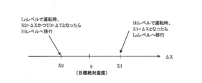
- control for switching the evaporation temperature level from the Hi level to the Lo level may be performed using the detected value of the indoor temperature and humidity.
- the difference ⁇ T obtained by subtracting the indoor target temperature Ta_tgt set by the target temperature / humidity setting means 44 from the indoor temperature Ta detected by the suction temperature / humidity detection means 43 as shown in FIG.
- the indoor target absolute humidity Xa_tgt set by the target temperature / humidity setting means 44 is subtracted from the indoor absolute humidity Xa detected by the suction temperature / humidity detection means 43.
- the difference ⁇ T obtained by subtracting the indoor target temperature Ta_tgt from the indoor temperature Ta is smaller than T3 (negative value), and FIG.
- the difference ⁇ X obtained by subtracting the indoor target temperature Ta_tgt from the indoor temperature Ta is smaller than a predetermined value X2 (0> X2), the sensible heat load and the latent heat load are excessively processed. It is determined that the evaporation temperature can be set high, and the evaporation temperature level is shifted from the Lo level to the Hi level. When the compressor is thermo-off during the Lo level operation, it may be shifted to the Hi level.
- the detection values of the RA temperature / humidity detection means 32 provided in the ventilation device 3 may be used.
- FIG. 13 shows an evaporation temperature control flow chart using the difference ⁇ T obtained by subtracting the indoor target temperature Ta_tgt from the room temperature Ta and the difference ⁇ X obtained by subtracting the indoor target absolute humidity Xa_tgt from the indoor absolute humidity Xa as control parameters.
- the temperature / humidity of the outside air is detected by the OA temperature / humidity detecting means 31 in S-1.
- S-2 determination of zone I to zone IV in FIG. 7 is performed according to the detected outside air temperature humidity.
- the evaporation temperature level (Hi level or Lo level) of the indoor heat exchanger 15 of the indoor unit 1 system and the ventilator cooler 18 of the 3 ventilation systems is determined based on FIG.
- a difference ⁇ T is calculated by subtracting the indoor target temperature Ta_tgt from the indoor temperature Ta
- a difference ⁇ X is calculated by subtracting the indoor target absolute humidity Xa_tgt from the indoor absolute humidity Xa.
- the evaporation temperature set value Te is determined based on FIG.
- the difference ⁇ T obtained by subtracting the indoor target temperature Ta_tgt from the indoor temperature Ta is T3 or more and T2 or less in FIG. 11, and the difference ⁇ X obtained by subtracting the indoor target absolute humidity Xa_tgt from the indoor absolute humidity Xa is shown in FIG.
- step S-7 it is determined whether ⁇ T is smaller than T3 and ⁇ X is smaller than X2, and if the condition is not satisfied, the process proceeds to S-8, and if the condition is satisfied, the process proceeds to S-9. If the process proceeds to S-8, it is determined whether ⁇ T is greater than T2 or ⁇ X is greater than X1, and if the condition is not satisfied, the process proceeds to S-13, and the end of operation is determined as described above. To do. If the condition is satisfied in S-8, the process proceeds to S-10, where it is determined whether the evaporation temperature of the indoor heat exchanger 15 is Hi level. If the condition is satisfied, the temperature or humidity reaches the indoor target temperature and humidity. In step S-12, the evaporating temperature level of the indoor heat exchanger 15 is changed to the Lo level. When the condition is not satisfied in S-10 and after proceeding to S-12, the process proceeds to S-13, and the end of operation is determined as described above.
- the process proceeds from S-7 to S-9, it is determined whether the evaporation temperature of the indoor heat exchanger 15 is at the Lo level. If the condition is satisfied, the process proceeds to S-11 and the evaporation temperature of the indoor heat exchanger 15 is determined. Change the level to Hi level. If the condition is not satisfied in S-9, the process proceeds to S-13, and the end of operation is determined as described above.
- the sensible heat load and the latent heat load are assumed from the outside air temperature humidity, and after determining the optimum evaporating temperature of the indoor heat exchanger 15 and the ventilator cooler 18 in the feedforward, the indoor temperature humidity Since the optimum evaporating temperature of the indoor heat exchanger 15 is corrected by feedback control using, the time required to find the optimum evaporating temperature is short, it is possible to follow load fluctuations, and the energy saving effect is enhanced.
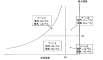
- Embodiment 2 the air diagram is divided into four zones with the dry air temperature T0 and the absolute humidity X0 as boundaries as shown in FIGS. 7 and 8, and in the same zone, the indoor heat exchanger 15 and the ventilation device are divided.
- the evaporation temperature level of the cooler 18 is set to a common Hi level or Lo level, in this embodiment, the evaporation temperature levels of the indoor heat exchanger 15 and the ventilator cooler 18 are set as shown in FIG. To do.
- Other components and evaporation temperature control are the same as those in the first embodiment.
- the evaporation temperature level in FIG. 6 can be set to the Hi level for both the indoor heat exchanger 15 and the ventilator cooler 18.
- the evaporating temperature level in FIG. 6 needs to be the Hi level for the indoor heat exchanger 15 and the Lo level for the ventilator cooler 18.
- the load is low. Therefore, even if the evaporation temperature of the ventilator cooler 18 that processes the latent heat load is increased, the dehumidification does not become insufficient, but the high sensible heat load.
- the evaporation temperature of the indoor heat exchanger 15 mainly composed of sensible heat is raised, insufficient cooling occurs. That is, the evaporation temperature level in FIG. 6 needs to be set to Lo level in the indoor heat exchanger 15, and the ventilator cooler 18 can be set to Hi level.
- the sensible heat load is high. Therefore, if the evaporation temperature of the indoor heat exchanger 15 is increased, the cooling becomes insufficient and the latent heat load is processed. Insufficient dehumidification occurs when the evaporation temperature of 18 is increased. That is, the evaporation temperature level in FIG. 6 needs to set both the indoor heat exchanger 15 and the ventilator cooler 18 to the Lo level.
- the sensible heat load and the latent heat load are more appropriately set by individually setting the evaporation temperature levels of the indoor heat exchanger 15 and the ventilator cooler 18 to the Hi level and the Lo level. Can be processed.
- the ET_max and ET_min are determined with the evaporation temperature level being the Hi level and the Lo level.
- a fixed value may be set such as fixed.
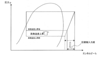
- the control according to Embodiments 1 and 2 makes it possible to achieve an optimal evaporation temperature according to the load. That is, the evaporating temperature set value Te can be increased while reliably processing the sensible heat load and the latent heat load, and as shown in FIG. 15, the compressor input is reduced and energy is saved. Moreover, since excessive processing of the sensible heat load and the latent heat load can be suppressed, the load is reduced and the energy saving effect is increased.
- the load is determined by detecting the outside air temperature and humidity, when it is determined that the load is low, it is possible to operate at a high evaporation temperature even at the start of operation. Energy saving effect at the time of cooling (during pull-down) can also be obtained.
- the evaporation temperature level is divided into a Hi level and a Lo level, but it may be divided into three or more.
- the target loss startsing / stopping loss
- the target SH superheat degree
Abstract
Description
しかしながら、蒸発温度を低温で一定として潜熱負荷を処理する運転では、運転効率が低下してしまうという問題があった。一方、蒸発温度を高めると運転効率は向上するが、潜熱処理量が不足して室内湿度が上昇し快適性が低下するという問題があった。 In order to process the latent heat load among these heat loads, the latent heat load has been processed with the refrigerant evaporation temperature of the indoor heat exchanger of the air conditioner kept constant at a low temperature.
However, in the operation in which the evaporation temperature is kept constant at a low temperature and the latent heat load is processed, there is a problem that the operation efficiency is lowered. On the other hand, when the evaporation temperature is increased, the operation efficiency is improved, but there is a problem that the amount of latent heat treatment is insufficient, the indoor humidity is increased, and the comfort is lowered.
そのため、空気調和装置と換気装置のそれぞれの蒸発器に外気温湿度条件や室内温湿度条件などを考慮した適切な蒸発温度を設定することができないという問題点があった。 However, in the air conditioning system including the conventional air conditioner and the ventilator as described above, the sensible heat is controlled by controlling the refrigeration cycle in each of the air conditioner and the ventilator and adjusting the evaporation temperature of each evaporator. Although the load and latent heat load are shared, the evaporating temperature of the ventilator is set based on the required dehumidification amount, and the evaporating temperature of the indoor heat exchanger of the air conditioner is set above the dew point temperature. It was a single setting method.
For this reason, there has been a problem that it is impossible to set an appropriate evaporating temperature in consideration of the outside air temperature humidity condition, the indoor temperature humidity condition, and the like in the respective evaporators of the air conditioner and the ventilator.
図1は、この本実施の形態1における空気調和システム概略図である。空気調和システム100は、1台または複数の室内機1と1台または複数の換気装置3が室外機2と冷媒配管104で接続されている。また、室内機1、室外機2、換気装置3は集中コントローラ102と伝送線103で接続されている。集中コントローラ102には、図示はしないが目標温湿度設定手段44が設けられている。
FIG. 1 is a schematic diagram of an air conditioning system according to the first embodiment. In the
共通の値とは、例えばETi_hi_max=ETv_hi_max=14℃、ETi_hi_min=ETv_hi_min=9℃、ETi_lo_max=ETv_lo_max=9℃、ETi_lo_min=ETv_lo_min=0℃となる。 The values of the maximum evaporation temperature ET_max and the minimum evaporation temperature ET_min of the
Common values are, for example, ETi_hi_max = ETv_hi_max = 14 ° C., ETi_hi_min = ETv_hi_min = 9 ° C., ETi_lo_max = ETv_lo_max = 9 ° C., ETi_lo_min = ETv_lo_min = 0 ° C.
この場合、室内熱交換器15と換気装置冷却器18の最大蒸発温度ET_maxと最小蒸発温度ET_minの値をそれぞれ最適値に設定することで、顕熱負荷と潜熱負荷をより適切に処理することが可能となる。 The different values are, for example, ETi_hi_max = 14 ° C., ETv_hi_max = 12 ° C., ETi_hi_min = 9 ° C., ETv_hi_min = 7 ° C., ETi_lo_max = 9 ° C., ETv_lo_max = 7 ° C., ETi_lo_min = 2 ° C., ETv_lo_min = 0 ° C.
In this case, the sensible heat load and the latent heat load can be more appropriately processed by setting the maximum evaporation temperature ET_max and the minimum evaporation temperature ET_min of the
換気装置3のOA温湿度検出手段31の検出値が、ゾーンIにある場合は、外気が低温/低湿度であるので、低顕熱/低潜熱負荷条件となっている。
ゾーンIIにある場合は、外気が低温/高湿度であるので、低顕熱/高潜熱負荷条件である。
ゾーンIIIにある場合は、外気が高温/低湿度であるので、高顕熱/低潜熱負荷条件となる。
ゾーンIVにある場合は、外気が高温/高湿度であるので、高顕熱/高潜熱負荷条件となる。 FIG. 7 is an air diagram in which the conditions of the outside air sucked into the
When the detected value of the OA temperature / humidity detecting means 31 of the
In the case of Zone II, since the outside air is low temperature / high humidity, it is a low sensible heat / high latent heat load condition.
In the case of Zone III, since the outside air is high temperature / low humidity, it becomes a high sensible heat / low latent heat load condition.
When it is in zone IV, since the outside air is high temperature / high humidity, it becomes a high sensible heat / high latent heat load condition.
よって、図6における蒸発温度レベルはHiレベルとすることができ、室内機系統の蒸発温度設定値Teは、ET_max=ETi_hi_maxからET_min=ETi_hi_minの間となり、室内温度Taから室内目標温度Ta_tgtを減算した温度差であるΔTに応じて、図5のように蒸発温度設定値Teが決定される。 Under the low sensible heat / low latent heat load condition (zone I), since the sensible heat load is low, there is no insufficient cooling even if the evaporation temperature of the sensible heat-based
Therefore, the evaporation temperature level in FIG. 6 can be set to the Hi level, and the evaporation temperature set value Te of the indoor unit system is between ET_max = ETi_hi_max and ET_min = ETi_hi_min, and the indoor target temperature Ta_tgt is subtracted from the indoor temperature Ta. The evaporation temperature set value Te is determined as shown in FIG. 5 according to ΔT which is a temperature difference.
以上から、蒸発温度レベルHiとLoは、外気条件によって図8のようにゾーンI~IVに分けて決定される。 Then, Te = ET_max when ΔT is 0, Te = ET_min when ΔT is T1, and between 0 ≦ ΔT ≦ T1, the evaporation temperature set value Te is determined to be proportional to ΔT between ET_max and ET_min. Is done.
From the above, the evaporation temperature levels Hi and Lo are determined by being divided into zones I to IV as shown in FIG. 8 according to the outside air conditions.
運転スタート後、S-1で、OA温湿度検出手段31で外気の温湿度を検出する。
S-2は、検出した外気温湿度に応じて、図7におけるゾーンI~ゾーンIVの判定を行う。
S-3は、室内機1系統の室内熱交換器15、換気装置3系統の換気装置冷却器18の蒸発温度レベル(HiレベルもしくはLoレベル)を図6に基づいて決定する。 FIG. 13 shows an evaporation temperature control flow chart using the difference ΔT obtained by subtracting the indoor target temperature Ta_tgt from the room temperature Ta and the difference ΔX obtained by subtracting the indoor target absolute humidity Xa_tgt from the indoor absolute humidity Xa as control parameters.
After the operation is started, the temperature / humidity of the outside air is detected by the OA temperature / humidity detecting means 31 in S-1.
In S-2, determination of zone I to zone IV in FIG. 7 is performed according to the detected outside air temperature humidity.
In S-3, the evaporation temperature level (Hi level or Lo level) of the
S-5は、図5に基づいて蒸発温度設定値Teを決定する。
S-6は、室内温度Taから室内目標温度Ta_tgtを減算した差ΔTが、図11におけるT3以上T2以下、かつ、室内絶対湿度Xaから室内目標絶対湿度Xa_tgtを減算した差ΔXが、図12におけるX2以上、X1以下であるかどうかを判定し、条件を満たさない場合は、S-7に進む。S-6で、条件を満たす場合は、S-13で運転終了かどうかの判定を行ない、終了しない場合は、S-1に戻り同様の処理を繰り返し、終了する場合はS-14で終了する。 In S-4, a difference ΔT is calculated by subtracting the indoor target temperature Ta_tgt from the indoor temperature Ta, and a difference ΔX is calculated by subtracting the indoor target absolute humidity Xa_tgt from the indoor absolute humidity Xa.
In S-5, the evaporation temperature set value Te is determined based on FIG.
In S-6, the difference ΔT obtained by subtracting the indoor target temperature Ta_tgt from the indoor temperature Ta is T3 or more and T2 or less in FIG. 11, and the difference ΔX obtained by subtracting the indoor target absolute humidity Xa_tgt from the indoor absolute humidity Xa is shown in FIG. It is determined whether or not X2 is equal to or greater than X1, and if the condition is not satisfied, the process proceeds to S-7. If the condition is satisfied in S-6, it is determined whether or not the operation is ended in S-13. If not, the process returns to S-1 and repeats the same process, and if finished, the process ends in S-14. .
上記実施の形態1では、空気線図を図7、8のように、外気条件を乾球温度T0、絶対湿度X0を境界として4つのゾーンに分け、同一ゾーンでは室内熱交換器15と換気装置冷却器18の蒸発温度レベルを共通のHiレベルもしくはLoレベルとしたが、本実施の形態では、図14に示すように、室内熱交換器15と換気装置冷却器18の蒸発温度レベルをそれぞれ設定する。その他の構成要素や蒸発温度制御は、実施の形態1と同様である。
In the first embodiment, the air diagram is divided into four zones with the dry air temperature T0 and the absolute humidity X0 as boundaries as shown in FIGS. 7 and 8, and in the same zone, the
よって、図6における蒸発温度レベルは、室内熱交換器15と換気装置冷却器18の双方共にHiレベルとすることができる。 That is, under the low sensible heat and low latent heat load conditions (zone I), since the load is low sensible heat, even if the evaporation temperature of the
Therefore, the evaporation temperature level in FIG. 6 can be set to the Hi level for both the
また、蒸発温度レベルがHiレベルの最大蒸発温度ET_max設定でも室内機1がサーモoffするような場合は、蒸発器の目標SH(過熱度)を大きくして、能力を落とすことで発停ロスを回避するようにしても良い。 Further, in
In addition, when the
Claims (12)
- 冷媒が循環する室外機と室内機と換気装置とで構成される冷媒系統を有し、
前記冷媒系統は、圧縮機、室外熱交換器、第1膨張弁、室内熱交換器、第2膨張弁、換気装置冷却器を有し、
前記室内機は、前記室内熱交換器、を有し、室内空気を温度調整しながら循環させるように構成され、
前記換気装置は、前記換気装置冷却器、を有し、室内空気と室外空気を入れ替えると共に、室内に導入される室外空気を前記換気装置冷却器で冷却除湿するように構成され、
前記室外機、前記室内機、前記換気装置は冷媒配管で接続されており、
室外空気の温湿度を検出する手段を有し、
室外空気温湿度に応じて前記室内熱交換器と前記換気装置冷却器の最大蒸発温度設定値と最小蒸発温度設定値を決定し、
前記室内熱交換器と前記換気装置冷却器の蒸発温度設定値は、前記最大蒸発温度設定値と前記最小蒸発温度設定値の間に設定され、
前記室内熱交換器と前記換気装置冷却器の蒸発温度は、前記蒸発温度設定値となるように制御されることを特徴とする空気調和システム。 It has a refrigerant system composed of an outdoor unit in which refrigerant circulates, an indoor unit, and a ventilator,
The refrigerant system includes a compressor, an outdoor heat exchanger, a first expansion valve, an indoor heat exchanger, a second expansion valve, and a ventilator cooler,
The indoor unit includes the indoor heat exchanger, and is configured to circulate indoor air while adjusting the temperature.
The ventilator has the ventilator cooler, and is configured to replace indoor air and outdoor air, and to cool and dehumidify outdoor air introduced into the room with the ventilator cooler,
The outdoor unit, the indoor unit, and the ventilation device are connected by a refrigerant pipe,
Having means for detecting the temperature and humidity of the outdoor air;
Determine the maximum evaporation temperature setting value and the minimum evaporation temperature setting value of the indoor heat exchanger and the ventilator cooler according to the outdoor air temperature and humidity,
The evaporation temperature setting value of the indoor heat exchanger and the ventilator cooler is set between the maximum evaporation temperature setting value and the minimum evaporation temperature setting value,
The air conditioning system characterized in that the evaporating temperatures of the indoor heat exchanger and the ventilator cooler are controlled to be the evaporating temperature set value. - 前記蒸発温度設定値は、検出した室内温度から、設定された室内目標温度を減算した温度差△Tに基づいて設定されることを特徴とする請求項1に記載の空気調和システム。 The air conditioning system according to claim 1, wherein the evaporating temperature set value is set based on a temperature difference ΔT obtained by subtracting the set indoor target temperature from the detected indoor temperature.
- 前記最大蒸発温度設定値と前記最小蒸発温度設定値は、それぞれ蒸発温度の高いHiレベル蒸発温度と、蒸発温度の低いLoレベル蒸発温度の2パターンの設定値を有し、前記Hiレベル蒸発温度と、前記Loレベル蒸発温度は、前記室外空気温湿度に基づいて変更されることを特徴とする請求項1または2に記載の空気調和システム。 The maximum evaporating temperature set value and the minimum evaporating temperature set value each have two patterns of set values, that is, a Hi level evaporating temperature with a high evaporating temperature and a Lo level evaporating temperature with a low evaporating temperature. The air conditioning system according to claim 1, wherein the Lo level evaporation temperature is changed based on the outdoor air temperature and humidity.
- 前記最大蒸発温度設定値と前記最小蒸発温度設定値は、前記室内熱交換器と前記換気装置冷却器で異なる設定値とすることを特徴とする請求項1~3のいずれか1項に記載の空気調和システム。 The maximum evaporating temperature set value and the minimum evaporating temperature set value are different set values for the indoor heat exchanger and the ventilator cooler, according to any one of claims 1 to 3. Air conditioning system.
- 前記室外空気温湿度は、空気線図上で所定の乾球温度の値T0と、所定の絶対湿度の値X0を閾値として4ゾーンに分割されることを特徴とする請求項1~4のいずれか1項に記載の空気調和システム。 5. The outdoor air temperature / humidity is divided into four zones on the air diagram with a predetermined dry bulb temperature value T0 and a predetermined absolute humidity value X0 as threshold values. The air conditioning system according to claim 1.
- 前記4ゾーンのうちの少なくとも前記乾球温度の値T0以下で、かつ、前記絶対湿度の値X0以下のゾーンは、前記最大蒸発温度設定値と前記最小蒸発温度設定値を蒸発温度の高いHiレベル蒸発温度に設定することを特徴とする請求項5に記載の空気調和システム。 Of the four zones, at least the dry bulb temperature value T0 or less and the absolute humidity value X0 or less zone is the Hi level where the maximum evaporation temperature setting value and the minimum evaporation temperature setting value are high. The air conditioning system according to claim 5, wherein the air conditioning system is set to an evaporation temperature.
- 前記4ゾーンのうちの少なくとも前記乾球温度の値T0以上で、かつ、前記絶対湿度の値X0以上のゾーンは、前記最大蒸発温度設定値と前記最小蒸発温度設定値を蒸発温度の低いLoレベル蒸発温度に設定することを特徴とする請求項5または6に記載の空気調和システム。 Among the four zones, at least the dry bulb temperature value T0 or more and the absolute humidity value X0 or more zone, the maximum evaporation temperature setting value and the minimum evaporation temperature setting value are set to the Lo level with a low evaporation temperature. It sets to evaporation temperature, The air conditioning system of Claim 5 or 6 characterized by the above-mentioned.
- 前記乾球温度の値T0と、前記絶対湿度の値X0は、設定された室内目標温度に基づいて変更されることを特徴とする請求項5~7のいずれか1項に記載の空気調和システム。 The air conditioning system according to any one of claims 5 to 7, wherein the dry bulb temperature value T0 and the absolute humidity value X0 are changed based on a set indoor target temperature. .
- 前記乾球温度の値T0と、前記絶対湿度の値X0は、前記換気装置の風量に基づいて変更されることを特徴とする請求項5~7のいずれか1項に記載の空気調和システム。 The air conditioning system according to any one of claims 5 to 7, wherein the dry bulb temperature value T0 and the absolute humidity value X0 are changed based on an air volume of the ventilation device.
- 前記Hiレベル蒸発温度に設定されている間に、前記温度差△Tが正の値である第1の規定値を超えた場合、または、検出した室内絶対湿度と設定された室内目標絶対湿度の絶対湿度差△Xが正の値である第2の規定値を超えた場合には、前記室内熱交換器の蒸発温度の設定値が前記Loレベル蒸発温度に変更されることを特徴とする請求項3~9のいずれか1項に記載の空気調和システム。 While the Hi level evaporation temperature is set, when the temperature difference ΔT exceeds the first specified value which is a positive value, or the detected indoor absolute humidity and the set indoor target absolute humidity When the absolute humidity difference ΔX exceeds a second predetermined value which is a positive value, the set value of the evaporation temperature of the indoor heat exchanger is changed to the Lo level evaporation temperature. Item 10. The air conditioning system according to any one of Items 3 to 9.
- 前記Loレベル蒸発温度に設定されている間に、前記温度差△Tが負の値である第3の規定値未満となり、かつ、検出した室内絶対湿度と設定された室内目標絶対湿度の絶対湿度差△Xが負の値である第4の規定値未満となった場合には、前記室内熱交換器の蒸発温度の設定値が前記Hiレベル蒸発温度に変更されることを特徴とする請求項3~10のいずれか1項に記載の空気調和システム。 While the Lo level evaporation temperature is set, the temperature difference ΔT is less than a third specified value which is a negative value, and the detected indoor absolute humidity and the set indoor target absolute humidity absolute humidity The set value of the evaporating temperature of the indoor heat exchanger is changed to the Hi level evaporating temperature when the difference ΔX is less than a negative fourth specified value. The air conditioning system according to any one of 3 to 10.
- 前記室内熱交換器と前記換気装置冷却器は、単一の冷凍サイクルの冷媒回路の圧縮機に対して並列に接続されることを特徴とする請求項1~11のいずれか1項に記載の空気調和システム。 The indoor heat exchanger and the ventilator cooler are connected in parallel to a compressor of a refrigerant circuit of a single refrigeration cycle, according to any one of claims 1 to 11. Air conditioning system.
Priority Applications (5)
| Application Number | Priority Date | Filing Date | Title |
|---|---|---|---|
| GB201519232A GB2529329B (en) | 2013-05-14 | 2013-05-14 | Air conditioning system |
| PCT/JP2013/063466 WO2014184883A1 (en) | 2013-05-14 | 2013-05-14 | Air conditioning system |
| US14/888,715 US9874360B2 (en) | 2013-05-14 | 2013-05-14 | Air-conditioning system |
| JP2015516805A JP5996107B2 (en) | 2013-05-14 | 2013-05-14 | Air conditioning system |
| CN201420142256.1U CN203823945U (en) | 2013-05-14 | 2014-03-27 | Air conditioning system |
Applications Claiming Priority (1)
| Application Number | Priority Date | Filing Date | Title |
|---|---|---|---|
| PCT/JP2013/063466 WO2014184883A1 (en) | 2013-05-14 | 2013-05-14 | Air conditioning system |
Publications (1)
| Publication Number | Publication Date |
|---|---|
| WO2014184883A1 true WO2014184883A1 (en) | 2014-11-20 |
Family
ID=51479435
Family Applications (1)
| Application Number | Title | Priority Date | Filing Date |
|---|---|---|---|
| PCT/JP2013/063466 WO2014184883A1 (en) | 2013-05-14 | 2013-05-14 | Air conditioning system |
Country Status (5)
| Country | Link |
|---|---|
| US (1) | US9874360B2 (en) |
| JP (1) | JP5996107B2 (en) |
| CN (1) | CN203823945U (en) |
| GB (1) | GB2529329B (en) |
| WO (1) | WO2014184883A1 (en) |
Cited By (6)
| Publication number | Priority date | Publication date | Assignee | Title |
|---|---|---|---|---|
| CN104776519A (en) * | 2015-05-04 | 2015-07-15 | 吉首大学 | Temperature and humidity adjustment device applied to waiting room |
| JP2018021683A (en) * | 2016-08-01 | 2018-02-08 | 株式会社竹中工務店 | Air conditioning system |
| JP2018194252A (en) * | 2017-05-19 | 2018-12-06 | ダイキン工業株式会社 | Air conditioning system |
| JP2018194253A (en) * | 2017-05-19 | 2018-12-06 | ダイキン工業株式会社 | Air conditioning system |
| EP3370005A4 (en) * | 2015-10-26 | 2019-06-05 | Mitsubishi Electric Corporation | Air-conditioning system |
| CN113028616A (en) * | 2021-03-11 | 2021-06-25 | 广东智博士系统集成控制有限公司 | Two ally oneself with confession water conservancy variable frequency control system with changes in temperature, hot water and new trend dehumidification |
Families Citing this family (10)
| Publication number | Priority date | Publication date | Assignee | Title |
|---|---|---|---|---|
| US20170198934A1 (en) * | 2016-01-08 | 2017-07-13 | General Electric Company | Air Conditioner Units with Improved Make-Up Air System |
| CN105509161B (en) * | 2016-01-27 | 2019-09-06 | 能节(北京)科技发展有限公司 | A kind of air-source Double-working-condition Split type air conditioner and operation method |
| WO2017175257A1 (en) * | 2016-04-07 | 2017-10-12 | 株式会社芝浦電子 | Dryer and absolute humidity difference sensor |
| CN110192069B (en) * | 2016-11-16 | 2021-03-16 | 三菱电机株式会社 | Air conditioner control device and air conditioner control method |
| DE112017007594T5 (en) | 2017-06-01 | 2020-03-12 | Mitsubishi Electric Corporation | Air conditioning system |
| CN108131751B (en) * | 2018-02-07 | 2023-04-25 | 乐易泰(宁波)热能设备有限公司 | Dehumidification heat pump system |
| JP7054308B2 (en) * | 2018-10-10 | 2022-04-13 | エスペック株式会社 | Environmental test equipment and air conditioning equipment |
| WO2020144808A1 (en) * | 2019-01-10 | 2020-07-16 | 三菱電機株式会社 | Air conditioning and ventilation system |
| KR20220040220A (en) * | 2020-09-23 | 2022-03-30 | 엘지전자 주식회사 | Multi-air conditioner for heating, cooling and air conditioning operations |
| CN114017902B (en) * | 2021-10-27 | 2022-11-11 | 珠海格力电器股份有限公司 | Equipment control method, device, equipment and storage medium |
Citations (5)
| Publication number | Priority date | Publication date | Assignee | Title |
|---|---|---|---|---|
| JP2005049059A (en) * | 2003-07-31 | 2005-02-24 | Daikin Ind Ltd | Air-conditioning system |
| JP2010071587A (en) * | 2008-09-19 | 2010-04-02 | East Japan Railway Co | Air conditioning system |
| JP2010107152A (en) * | 2008-10-31 | 2010-05-13 | Mitsubishi Electric Corp | Refrigerating air-conditioning device |
| JP2010249485A (en) * | 2009-03-24 | 2010-11-04 | Mitsubishi Electric Corp | Air conditioner and air conditioning system |
| JP2013072590A (en) * | 2011-09-27 | 2013-04-22 | Mitsubishi Electric Corp | Air conditioning system |
Family Cites Families (6)
| Publication number | Priority date | Publication date | Assignee | Title |
|---|---|---|---|---|
| US5257736A (en) * | 1992-08-06 | 1993-11-02 | Donald Roy | Self-regulating air ventilation apparatus |
| US20080003940A1 (en) * | 1998-11-09 | 2008-01-03 | Building Performance Equipment, Inc. | Ventilator system and method |
| JP4513380B2 (en) | 2004-03-31 | 2010-07-28 | ダイキン工業株式会社 | Air conditioning system |
| JP2010065977A (en) | 2008-09-12 | 2010-03-25 | Daikin Ind Ltd | Air conditioning system |
| CN103717976B (en) * | 2011-07-27 | 2017-04-12 | 三菱电机株式会社 | Humidity controller and air conditioning system |
| US10006649B2 (en) * | 2013-03-05 | 2018-06-26 | Mitsubishi Electric Corporation | Air-conditioning system |
-
2013
- 2013-05-14 JP JP2015516805A patent/JP5996107B2/en active Active
- 2013-05-14 WO PCT/JP2013/063466 patent/WO2014184883A1/en active Application Filing
- 2013-05-14 GB GB201519232A patent/GB2529329B/en active Active
- 2013-05-14 US US14/888,715 patent/US9874360B2/en active Active
-
2014
- 2014-03-27 CN CN201420142256.1U patent/CN203823945U/en not_active Expired - Lifetime
Patent Citations (5)
| Publication number | Priority date | Publication date | Assignee | Title |
|---|---|---|---|---|
| JP2005049059A (en) * | 2003-07-31 | 2005-02-24 | Daikin Ind Ltd | Air-conditioning system |
| JP2010071587A (en) * | 2008-09-19 | 2010-04-02 | East Japan Railway Co | Air conditioning system |
| JP2010107152A (en) * | 2008-10-31 | 2010-05-13 | Mitsubishi Electric Corp | Refrigerating air-conditioning device |
| JP2010249485A (en) * | 2009-03-24 | 2010-11-04 | Mitsubishi Electric Corp | Air conditioner and air conditioning system |
| JP2013072590A (en) * | 2011-09-27 | 2013-04-22 | Mitsubishi Electric Corp | Air conditioning system |
Cited By (6)
| Publication number | Priority date | Publication date | Assignee | Title |
|---|---|---|---|---|
| CN104776519A (en) * | 2015-05-04 | 2015-07-15 | 吉首大学 | Temperature and humidity adjustment device applied to waiting room |
| EP3370005A4 (en) * | 2015-10-26 | 2019-06-05 | Mitsubishi Electric Corporation | Air-conditioning system |
| JP2018021683A (en) * | 2016-08-01 | 2018-02-08 | 株式会社竹中工務店 | Air conditioning system |
| JP2018194252A (en) * | 2017-05-19 | 2018-12-06 | ダイキン工業株式会社 | Air conditioning system |
| JP2018194253A (en) * | 2017-05-19 | 2018-12-06 | ダイキン工業株式会社 | Air conditioning system |
| CN113028616A (en) * | 2021-03-11 | 2021-06-25 | 广东智博士系统集成控制有限公司 | Two ally oneself with confession water conservancy variable frequency control system with changes in temperature, hot water and new trend dehumidification |
Also Published As
| Publication number | Publication date |
|---|---|
| JP5996107B2 (en) | 2016-09-21 |
| GB2529329B (en) | 2020-01-01 |
| US9874360B2 (en) | 2018-01-23 |
| GB201519232D0 (en) | 2015-12-16 |
| US20160084511A1 (en) | 2016-03-24 |
| CN203823945U (en) | 2014-09-10 |
| GB2529329A (en) | 2016-02-17 |
| JPWO2014184883A1 (en) | 2017-02-23 |
Similar Documents
| Publication | Publication Date | Title |
|---|---|---|
| JP5996107B2 (en) | Air conditioning system | |
| JP6072221B2 (en) | Air conditioning system | |
| JP5328951B2 (en) | Air conditioning system | |
| WO2013099913A1 (en) | Air-conditioning system that adjusts temperature and humidity | |
| JP5487857B2 (en) | Air conditioning system | |
| JP5984964B2 (en) | Air conditioning system | |
| JP5336133B2 (en) | Air conditioning system | |
| JP2013072590A (en) | Air conditioning system | |
| JP6250148B2 (en) | Air conditioning system | |
| JP4274326B2 (en) | Dehumidification control method for air conditioning system | |
| JP5772157B2 (en) | Air conditioning system | |
| JP6213781B2 (en) | External controller control method | |
| JP2016095102A (en) | Control device of outdoor air conditioner | |
| JP6938950B2 (en) | Air conditioning system | |
| JP6370425B2 (en) | Air conditioner using direct expansion coil | |
| JP6784533B2 (en) | Air conditioning system | |
| WO2018211612A1 (en) | Air conditioning device | |
| JP2019011950A (en) | Air conditioner | |
| JP2014137207A (en) | Air conditioning system | |
| JP6239100B2 (en) | Air conditioning system | |
| JP2015218986A (en) | Air conditioner | |
| JP2020016419A (en) | Air conditioning system | |
| JP2020020488A (en) | Air conditioning system |
Legal Events
| Date | Code | Title | Description |
|---|---|---|---|
| 121 | Ep: the epo has been informed by wipo that ep was designated in this application |
Ref document number: 13884727 Country of ref document: EP Kind code of ref document: A1 |
|
| ENP | Entry into the national phase |
Ref document number: 2015516805 Country of ref document: JP Kind code of ref document: A |
|
| ENP | Entry into the national phase |
Ref document number: 1519232 Country of ref document: GB Kind code of ref document: A Free format text: PCT FILING DATE = 20130514 |
|
| WWE | Wipo information: entry into national phase |
Ref document number: 1519232.1 Country of ref document: GB |
|
| WWE | Wipo information: entry into national phase |
Ref document number: 14888715 Country of ref document: US |
|
| NENP | Non-entry into the national phase |
Ref country code: DE |
|
| 122 | Ep: pct application non-entry in european phase |
Ref document number: 13884727 Country of ref document: EP Kind code of ref document: A1 |