WO2014181708A1 - Construction equipment - Google Patents
Construction equipment Download PDFInfo
- Publication number
- WO2014181708A1 WO2014181708A1 PCT/JP2014/061705 JP2014061705W WO2014181708A1 WO 2014181708 A1 WO2014181708 A1 WO 2014181708A1 JP 2014061705 W JP2014061705 W JP 2014061705W WO 2014181708 A1 WO2014181708 A1 WO 2014181708A1
- Authority
- WO
- WIPO (PCT)
- Prior art keywords
- hydraulic hose
- swing post
- hydraulic
- swing
- construction machine
- Prior art date
Links
Images


Classifications
-
- E—FIXED CONSTRUCTIONS
- E02—HYDRAULIC ENGINEERING; FOUNDATIONS; SOIL SHIFTING
- E02F—DREDGING; SOIL-SHIFTING
- E02F3/00—Dredgers; Soil-shifting machines
- E02F3/04—Dredgers; Soil-shifting machines mechanically-driven
- E02F3/28—Dredgers; Soil-shifting machines mechanically-driven with digging tools mounted on a dipper- or bucket-arm, i.e. there is either one arm or a pair of arms, e.g. dippers, buckets
- E02F3/30—Dredgers; Soil-shifting machines mechanically-driven with digging tools mounted on a dipper- or bucket-arm, i.e. there is either one arm or a pair of arms, e.g. dippers, buckets with a dipper-arm pivoted on a cantilever beam, i.e. boom
- E02F3/32—Dredgers; Soil-shifting machines mechanically-driven with digging tools mounted on a dipper- or bucket-arm, i.e. there is either one arm or a pair of arms, e.g. dippers, buckets with a dipper-arm pivoted on a cantilever beam, i.e. boom working downwardly and towards the machine, e.g. with backhoes
- E02F3/325—Backhoes of the miniature type
-
- E—FIXED CONSTRUCTIONS
- E02—HYDRAULIC ENGINEERING; FOUNDATIONS; SOIL SHIFTING
- E02F—DREDGING; SOIL-SHIFTING
- E02F3/00—Dredgers; Soil-shifting machines
- E02F3/04—Dredgers; Soil-shifting machines mechanically-driven
- E02F3/28—Dredgers; Soil-shifting machines mechanically-driven with digging tools mounted on a dipper- or bucket-arm, i.e. there is either one arm or a pair of arms, e.g. dippers, buckets
- E02F3/30—Dredgers; Soil-shifting machines mechanically-driven with digging tools mounted on a dipper- or bucket-arm, i.e. there is either one arm or a pair of arms, e.g. dippers, buckets with a dipper-arm pivoted on a cantilever beam, i.e. boom
- E02F3/32—Dredgers; Soil-shifting machines mechanically-driven with digging tools mounted on a dipper- or bucket-arm, i.e. there is either one arm or a pair of arms, e.g. dippers, buckets with a dipper-arm pivoted on a cantilever beam, i.e. boom working downwardly and towards the machine, e.g. with backhoes
-
- E—FIXED CONSTRUCTIONS
- E02—HYDRAULIC ENGINEERING; FOUNDATIONS; SOIL SHIFTING
- E02F—DREDGING; SOIL-SHIFTING
- E02F3/00—Dredgers; Soil-shifting machines
- E02F3/04—Dredgers; Soil-shifting machines mechanically-driven
- E02F3/28—Dredgers; Soil-shifting machines mechanically-driven with digging tools mounted on a dipper- or bucket-arm, i.e. there is either one arm or a pair of arms, e.g. dippers, buckets
- E02F3/36—Component parts
- E02F3/38—Cantilever beams, i.e. booms;, e.g. manufacturing processes, forms, geometry or materials used for booms; Dipper-arms, e.g. manufacturing processes, forms, geometry or materials used for dipper-arms; Bucket-arms
- E02F3/382—Connections to the frame; Supports for booms or arms
- E02F3/384—Connections to the frame; Supports for booms or arms the boom being pivotable relative to the frame about a vertical axis
-
- E—FIXED CONSTRUCTIONS
- E02—HYDRAULIC ENGINEERING; FOUNDATIONS; SOIL SHIFTING
- E02F—DREDGING; SOIL-SHIFTING
- E02F9/00—Component parts of dredgers or soil-shifting machines, not restricted to one of the kinds covered by groups E02F3/00 - E02F7/00
- E02F9/18—Counterweights
-
- E—FIXED CONSTRUCTIONS
- E02—HYDRAULIC ENGINEERING; FOUNDATIONS; SOIL SHIFTING
- E02F—DREDGING; SOIL-SHIFTING
- E02F9/00—Component parts of dredgers or soil-shifting machines, not restricted to one of the kinds covered by groups E02F3/00 - E02F7/00
- E02F9/20—Drives; Control devices
- E02F9/22—Hydraulic or pneumatic drives
- E02F9/2264—Arrangements or adaptations of elements for hydraulic drives
- E02F9/2275—Hoses and supports therefor and protection therefor
Definitions
- the present invention relates to a construction machine such as a hydraulic excavator provided with a swing post attached with a working device and swinging in the left-right direction and a hydraulic hose extending upward through a pair of side plates of the swing post.
- a construction machine such as a hydraulic excavator provided with a swing post attached with a working device and swinging in the left-right direction and a hydraulic hose extending upward through a pair of side plates of the swing post.
- Patent Document 1 There is a technique disclosed in Patent Document 1 as this type of prior art.
- This prior art is a hydraulic excavator, for example, a mini excavator.
- the mini excavator is disposed at a front position of a swing frame of a swing body and a swing body constituting the vehicle body, and is swingable in a lateral direction.
- a bracket that is, a swing post, a work device attached to the boom swing bracket and including a hydraulic cylinder, and a counterweight disposed at the rear portion of the swing frame of the swing body to ensure a weight balance with the work device. .
- a driver's seat is disposed on the revolving frame of the revolving structure, and a handrail that constitutes the structure is disposed at a front position of the revolving structure, that is, a front side position of the driver's seat.
- the boom swing bracket and the swing frame of the swing body forming the vehicle body are connected to each other, and a pair of support shafts that are vertically arranged through a gap and extend in the vertical direction, that is, an upper support shaft and a lower support shaft, It has.
- a boom and a boom cylinder that form a working device are attached to the boom swing bracket.
- this prior art is included in the working device, extending upward through the above-described gap formed between the pair of support shafts so as to pass between the pair of opposing side plates of the boom swing bracket.
- a plurality of hydraulic hoses for guiding pressure oil for driving hydraulic cylinders such as boom cylinders and arm cylinders are provided.
- the hydraulic hose is attached and held in a hose clamp attached to a wall plate to which a pair of side plates are fixed, in the boom swing bracket.
- the boom swing bracket is arranged in this way, the distance from the turning center of the revolving structure to the tip of the working device when the boom, arm, and bucket included in the working device are extended in the horizontal direction, that is, the reach is long. Therefore, the moment at the time of work becomes large, and it is necessary to provide a heavy weight counterweight corresponding to such a large moment.
- the boom swing bracket that is, the swing post
- the revolving body that is, the structure disposed at the front position of the vehicle body
- the present invention has been made in the state of the prior art described above, and its purpose is to allow the swing post to be mounted on the vehicle body without causing interference between the expansion portion of the hydraulic hose and the structure disposed at the front position of the vehicle body. It is an object of the present invention to provide a construction machine that can be disposed so as to be close to a structure disposed at a front surface position.
- the present invention provides a vehicle body, a swing post attached to the vehicle body and swingable in the left-right direction, a working device attached to the swing post and including a hydraulic cylinder, and a rear portion of the vehicle body.
- the counterweight that is disposed on the counter and secures a weight balance with the working device, and extends upward through a pair of opposing side plates of the swing post, and drives the hydraulic cylinder of the working device.
- the hydraulic hose is provided on the swing post, and the hydraulic hose expands in a direction toward a structure disposed at a front position of the vehicle body as the working device is driven.
- the first guide portion for guiding the hydraulic hose downward while restricting the movement of the hydraulic hose toward the structure It is characterized in that was example.
- the swing post can be disposed so as to approach the structure disposed at the front surface position of the vehicle body. Accordingly, the present invention can shorten the distance from the center of the vehicle body to the tip of the working device, reduce the moment during work, and reduce the weight of the counterweight accordingly. Can do.
- the present invention is the above invention, wherein the first guide portion includes a flat plate portion attached to the swing post, and a surface portion that is erected from the flat plate portion and is disposed so as to face the expansion portion of the hydraulic hose. And a guide plate having an inclined plate portion formed so as to approach the structure as it goes upward.
- the inclined plate portion of the guide plate approaches the structure in which the hydraulic hose is disposed at the front position of the vehicle body.
- the movement of the hydraulic hose that is expanded according to the inclination angle of the inclined plate portion can be smoothly guided downward.
- the hydraulic hose when expanded has a high rigidity and gives a large pressing force to the inclined plate portion.
- a large area of the contact portion of the inclined plate portion that the hydraulic hose contacts can be ensured.
- the contact surface pressure against the inclined plate portion of the hydraulic hose can be kept low. Thereby, the wear of the hydraulic hose that contacts the guide plate can be prevented.
- the present invention is the above invention, wherein the hydraulic cylinder of the working device includes a specific hydraulic cylinder having one end connected to the swing post, and is provided on the swing post, and the hydraulic pressure is increased as the working device is driven.
- a second guide portion that guides the hydraulic hose downward while restricting movement of the hydraulic hose toward the specific hydraulic cylinder when the hose is about to expand in a direction toward the specific hydraulic cylinder; It is characterized by that.
- the hydraulic hose when the hydraulic hose expands in the direction toward the specific hydraulic cylinder during the operation of driving the working device, the movement of the hydraulic hose in the direction approaching the specific hydraulic cylinder by the second guide portion. Is regulated. At this time, the hydraulic hose is guided downward by the second guide portion, and the shape of the expanded portion of the hydraulic hose is kept small. Therefore, interference between the hydraulic hose and the specific hydraulic cylinder can be reliably prevented.
- the second guide portion has a surface portion disposed so as to face a rod extending in a left-right direction orthogonal to an extending direction of the hydraulic hose, or an expansion portion of the hydraulic hose. It is characterized by comprising a plate member.
- the second guide portion when the second guide portion is constituted by a rod, the second guide portion can have a simple structure, which is highly practical and contributes to a reduction in manufacturing cost. Moreover, when the 2nd guide part is comprised with a plate member, the contact surface pressure of the hydraulic hose which contacts a 2nd guide part can be restrained low, and wear-out of a hydraulic hose can be prevented.
- the present invention is the above invention, wherein the construction machine is disposed at a traveling body and a turning body constituting a vehicle body, a driver seat provided on a turning frame of the turning body, and a front position of the driver seat, A swing excavator including a handrail that forms a structure, and the swing post is attached to a front side position of the swing frame of the swing body, and the work device includes a boom connected to the swing post.
- the specific hydraulic cylinder includes a boom cylinder that drives the boom.
- the present invention configured as described above can be arranged so that the swing post is brought close to the handrail without causing interference between the expanded portion of the hydraulic hose and the handrail disposed at the front side position of the driver's seat. Thereby, the weight of a counterweight can be reduced and size reduction of the said mini excavator can be implement
- the present invention is provided on a swing post, and when the hydraulic hose is about to expand in a direction toward the structure disposed at the front position of the vehicle body as the working device is driven, the hydraulic hose approaches the structure of the hydraulic hose. Since the first guide portion that guides the hydraulic hose downward is provided while restricting the movement, interference between the expansion portion of the hydraulic hose and the structure disposed at the front position of the vehicle body occurs.
- the swing post can be disposed so as to be close to the structure disposed at the front position of the vehicle body.
- the present invention can reduce the distance from the center of the vehicle body to the tip of the work device when the work device is extended in the horizontal direction, that is, reach, and can keep the moment during work small. it can. In connection with this, the weight of a counterweight can be reduced rather than before. Therefore, the present invention can realize downsizing and weight reduction of the construction machine, which has been difficult in the past.
- FIG. 1 It is a side view which shows the mini excavator which comprises 1st Embodiment of the construction machine which concerns on this invention. It is the side view which expanded and showed the swing post part with which 1st Embodiment is equipped. It is principal part front sectional drawing of FIG. It is a perspective view which shows the guide plate part which comprises the 1st guide part with which 1st Embodiment is equipped. It is the perspective view which decomposed
- FIG. 10 is a perspective view showing a state in which a guide plate constituting the second guide portion is removed from the state shown in FIG. 9.
- the first embodiment of the construction machine of the present invention is a mini excavator constituting, for example, a small machine, and this mini excavator is disposed on the traveling body 1 constituting the vehicle body and the traveling body 1 as shown in FIG.
- the revolving body 2 is provided.
- the mini excavator is attached to the front side position of the revolving frame 2a of the revolving structure 2 and is attached to the swing post 3 swingable in the left-right direction, and to the swing post 3 so as to be rotatable in the vertical direction.
- a work device 4 for performing excavation work and the like is provided.
- the working device 4 includes a boom 5 attached to the swing post 3, an arm 6 attached to the tip of the boom 5, and a bucket 7 attached to the tip of the arm 6.
- the work device 4 includes a plurality of hydraulic cylinders, that is, a boom cylinder 5 a that drives the boom 4, an arm cylinder 6 a that drives the arm 6, and a bucket cylinder 7 a that drives the bucket 7.
- the boom cylinder 5 a described above constitutes a specific hydraulic cylinder whose one end is connected to the swing post 3.
- the driver's seat 8 is arranged on the turning frame 2a of the turning body 2, and a canopy 9 is provided so as to cover the upper side of the driver's seat 8.
- a counterweight 10 that secures a weight balance with the work device 4 is disposed at the rear of the driver's seat 8.
- a handrail 11 that constitutes a structure arranged at the front face position of the vehicle body, that is, the turning body 2 is arranged.
- the present embodiment connects the swing post 3 and the swing frame 2, and is arranged vertically with a gap 13 therebetween, and an upper support shaft 12 a that extends in the vertical direction, and a lower support shaft. 12b.
- the gap 13 between the upper support shaft 12a and the lower support shaft 12b passes through the space between the opposing side plates 3a and 3b of the swing post 3 and moves upward.
- a plurality of hydraulic hoses 14 that guide the pressure oil that drives the boom cylinder 5a and the arm cylinder 6a described above.
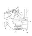
- the hydraulic hose 14 is provided on the swing post 3 and the hydraulic hose 14 tries to expand in a direction toward the handrail 11, for example, the structure disposed at the front surface position of the swing body 2 as the working device 4 is driven.
- the hydraulic hose 14 is provided with a first guide portion that guides the hydraulic hose 14 downward while restricting the movement of the hydraulic hose 14 in the direction approaching the handrail 11.
- the first guide part is composed of a guide plate 20.
- the guide plate 20 has holes 20b1 and 20b2 that respectively fit into screw holes 3c and 3d formed in the swing post 3, and are inserted into these holes 20b1 and 20b2.
- a flat plate portion 20b attached to the swing post 3 is provided by bolts 21a and 21b screwed into the screw holes 3c and 3d.
- the guide plate 20 has a surface portion that is erected from the flat plate portion 20b and is disposed so as to face the expansion portion of the hydraulic hose 14 that has expanded as the work device 4 is driven. 11 is provided with an inclined plate portion 20a formed so as to approach 11.
- the present embodiment is provided on the swing post 3, and the hydraulic hose 14 expands in the direction toward the above-described specific hydraulic cylinder, that is, the boom cylinder 5a as the working device 4 is driven.
- a second guide portion for example, a rod 22 that guides the hydraulic hose 14 downward while restricting the movement of the hydraulic hose 14 toward the boom cylinder 5 a.
- the rod 22 is extended in the left-right direction perpendicular to the extending direction of the hydraulic hose 14 so that one end is inserted through the side plate 3a of the swing post 3 and the other end is inserted through the side plate 3b. It is fixed to.
- the hydraulic hose 14 first expands in the direction toward the handrail 11 as shown in FIG. . Due to this expansion, the expanded portion of the hydraulic hose 14 contacts the inclined plate portion 20 a of the guide plate 20. Therefore, the hydraulic hose 14 is regulated by the inclined plate portion 20a of the guide plate 20 so as not to approach the handrail 11 any more.
- this embodiment when the hydraulic hose 14 expands in the direction toward the handrail 11, the movement of the hydraulic hose 14 in the direction approaching the handrail 11 is restricted by the guide plate 20. At this time, the hydraulic hose 14 is guided downward by the guide plate 20, and the shape of the expanded portion of the hydraulic hose 14 is kept small. Thereby, this embodiment can prevent interference with the hydraulic hose 14 and the handrail 11. FIG. Therefore, this embodiment can arrange
- the present embodiment when the boom 5, arm 6, and bucket 7 of the working device 4 are extended in the horizontal direction, the working device is moved from the center of the vehicle body, that is, the turning center of the swivel body 2.
- the distance to the tip of the bucket 4, that is, the reach can be shortened, and the moment during work can be kept small. Accordingly, the present embodiment can reduce the weight of the counterweight 10. Therefore, this embodiment can realize miniaturization and weight reduction of the mini excavator.
- the first guide portion that guides the hydraulic hose 14 downward while restricting the movement of the hydraulic hose 14 in the direction approaching the handrail 11 includes the guide plate 20 having the inclined plate portion 20a. Therefore, when the expanded hydraulic hose 14 comes into contact with the surface portion of the inclined plate portion 20a of the guide plate 20, its movement is restricted by the inclined plate portion 20a so that the hydraulic hose 14 does not approach the handrail 11, and the inclined The hydraulic hose 14 expanded according to the inclination angle of the plate portion 20a can be smoothly guided downward.
- the hydraulic hose 14 when expanded has high rigidity and gives a large pressing force to the inclined plate portion 20a. At this time, a large area of the contact portion of the inclined plate portion 20a with which the hydraulic hose 14 contacts is ensured. Therefore, the contact surface pressure with respect to the inclined plate part 20a of the hydraulic hose 14 can be kept low. Thereby, the wear of the hydraulic hose 14 in contact with the guide plate 20 can be prevented.
- the present embodiment includes the second guide portion including the rod 22 that guides the hydraulic hose 14 downward while restricting the movement of the hydraulic hose 14 in the direction approaching the boom cylinder 5a.
- the second guide portion including the rod 22 that guides the hydraulic hose 14 downward while restricting the movement of the hydraulic hose 14 in the direction approaching the boom cylinder 5a.
- FIG. 9 is a perspective view showing a main part configuration of the construction machine according to the second embodiment of the present invention
- FIG. 10 is a perspective view showing a state in which the guide plate constituting the second guide part is removed from the state shown in FIG. is there.
- the configuration of the second guide portion that guides the hydraulic hose 14 downward while restricting the movement of the hydraulic hose 14 in the direction approaching the boom cylinder 5a is different from the first embodiment.
- the second embodiment is also a mini excavator similar to that shown in FIG. 1, for example, and the basic configuration, that is, the configuration of the first guide portion and the like is the same as that of the first embodiment.
- the second guide portion is composed of a plate member 30 having a surface portion disposed so as to face the expansion portion of the hydraulic hose 14.
- brackets 32a and 32b having screw holes 33a and 33b are fixed to the swing post 3, and bolts 31a screwed into the screw holes 3a and 33b of the brackets 32a and 32b, respectively.
- 31b fasten the plate member 30 to the brackets 32a, 32b.
- the second embodiment configured as described above can basically obtain the same operational effects as those of the first embodiment described above. Further, in this second embodiment, since the second guide portion is composed of the plate member 30, it is possible to ensure a large area of the contact portion of the plate member 30 that contacts the expansion portion of the hydraulic hose 14, so that the hydraulic hose The contact surface pressure with respect to the 14 plate members 30 can be kept low. Thereby, wear of the hydraulic hose 14 in contact with the plate member 30 can be prevented.
- Running body (car body) 2 Revolving body (car body) 2a slewing frame 3 swing post 3a side plate 3b side plate 4 working device 5 boom 5a boom cylinder (specific hydraulic cylinder) 6 Arm 6a Arm cylinder (hydraulic cylinder) 7 Bucket 7a Bucket cylinder (hydraulic cylinder) 8 Driver's seat 10
- Counterweight 11 Handrail (structure) 14 Hydraulic hose 20 Guide plate (first guide part) 20a Inclined plate portion 20b Flat plate portion 22 Rod (second guide portion) 30 Plate member (second guide part)
Abstract
Description
2 旋回体(車体)
2a 旋回フレーム
3 スイングポスト
3a 側板
3b 側板
4 作業装置
5 ブーム
5a ブームシリンダ(特定油圧シリンダ)
6 アーム
6a アームシリンダ(油圧シリンダ)
7 バケット
7a バケットシリンダ(油圧シリンダ)
8 運転席
10 カウンタウェイト
11 手摺り(構造物)
14 油圧ホース
20 ガイドプレート(第1ガイド部)
20a 傾斜板部
20b 平板部
22 ロッド(第2ガイド部)
30 板部材(第2ガイド部) 1 Running body (car body)
2 Revolving body (car body)
6
7
8 Driver's
14
20a
30 Plate member (second guide part)
Claims (6)
- 車体(2)と、この車体(2)に取り付けられ左右方向に揺動可能なスイングポスト(3)と、このスイングポスト(3)に取り付けられ、油圧シリンダ(5a,6a,7a)を含む作業装置(4)と、上記車体(2)の後部に配置され、上記作業装(4)との重量バランスを確保するカウンタウェイト(10)と、上記スイングポスト(3)の対向する一対の側板(3a,3b)間を通って上方向に向かって延設され、上記作業装置(4)の上記油圧シリンダ(5a,6a,7a)を駆動する圧油を導く油圧ホース(14)とを備えた建設機械において、
上記スイングポスト(3)に設けられ、上記作業装置(4)の駆動に伴って上記油圧ホース(14)が上記車体(2)の前面位置に配置された構造物(11)に向かう方向に膨張しようとする際に、上記油圧ホース(14)の上記構造物(11)に近づく方向の動きを規制しながら、上記油圧ホース(14)を下方向へ案内する第1ガイド部(20)を備えたことを特徴とする建設機械。 Work including a vehicle body (2), a swing post (3) attached to the vehicle body (2) and swingable in the left-right direction, and a hydraulic cylinder (5a, 6a, 7a) attached to the swing post (3) A counterweight (10) disposed at the rear of the device (4) and the vehicle body (2) to ensure a weight balance with the work equipment (4), and a pair of side plates facing the swing post (3) ( 3a, 3b) and a hydraulic hose (14) that extends upward and leads the hydraulic oil that drives the hydraulic cylinders (5a, 6a, 7a) of the working device (4). In construction machinery
Provided on the swing post (3), the hydraulic hose (14) expands in a direction toward the structure (11) disposed at the front position of the vehicle body (2) as the work device (4) is driven. A first guide portion (20) for guiding the hydraulic hose (14) downward is provided while restricting movement of the hydraulic hose (14) in a direction approaching the structure (11) when attempting to do so. Construction machinery characterized by that. - 請求項1に記載の建設機械において、
上記第1ガイド部は、上記スイングポスト(3)に取り付けられる平板部(20b)と、この平板部(20b)から立設され、上記油圧ホース(14)の膨張部分に対向するように配置される面部を有し、上方に向かうに従って上記構造物(11)に近づくように形成された傾斜板部(20a)とを有するガイドプレート(20)から成ることを特徴とする建設機械。 The construction machine according to claim 1,
The first guide portion is erected from a flat plate portion (20b) attached to the swing post (3) and the flat plate portion (20b), and is disposed so as to face the expansion portion of the hydraulic hose (14). A construction machine comprising a guide plate (20) having an inclined plate portion (20a) formed so as to approach the structure (11) as it goes upward. - 請求項1に記載の建設機械において、
上記作業装置(4)の上記油圧シリンダは、上記スイングポスト(3)に一端が連結される特定油圧シリンダ(5a)を含み、
上記スイングポスト(3)に設けられ、上記作業装置(4)の駆動に伴って上記油圧ホース(14)が上記特定油圧シリンダ(5a)に向かう方向に膨張しようとする際に、上記油圧ホース(14)の上記特定油圧シリンダ(5a)に近づく方向の動きを規制しながら、上記油圧ホース(14)を下方向へ案内する第2ガイド部(22,30)を備えたことを特徴とする建設機械。 The construction machine according to claim 1,
The hydraulic cylinder of the working device (4) includes a specific hydraulic cylinder (5a) having one end connected to the swing post (3),
When the hydraulic hose (14) is provided on the swing post (3) and expands in the direction toward the specific hydraulic cylinder (5a) as the work device (4) is driven, the hydraulic hose ( 14) Construction comprising a second guide portion (22, 30) for guiding the hydraulic hose (14) downward while restricting movement toward the specific hydraulic cylinder (5a) of 14) machine. - 請求項2に記載の建設機械において、
上記作業装置(4)の上記油圧シリンダは、上記スイングポスト(3)に一端が連結される特定油圧シリンダ(5a)を含み、
上記スイングポスト(3)に設けられ、上記作業装置(4)の駆動に伴って上記油圧ホース(14)が上記特定油圧シリンダ(5a)に向かう方向に膨張しようとする際に、上記油圧ホース(14)の上記特定油圧シリンダ(5a)に近づく方向の動きを規制しながら、上記油圧ホース(14)を下方向へ案内する第2ガイド部(22,30)を備えたことを特徴とする建設機械。 The construction machine according to claim 2,
The hydraulic cylinder of the working device (4) includes a specific hydraulic cylinder (5a) having one end connected to the swing post (3),
When the hydraulic hose (14) is provided on the swing post (3) and expands in the direction toward the specific hydraulic cylinder (5a) as the work device (4) is driven, the hydraulic hose ( 14) Construction comprising a second guide portion (22, 30) for guiding the hydraulic hose (14) downward while restricting movement toward the specific hydraulic cylinder (5a) of 14) machine. - 請求項3に記載の建設機械において、
上記第2ガイド部は、上記油圧ホース(14)の延設方向に直交する左右方向に延設されたロッド(22)、または上記油圧ホース(14)の膨張部分に対向するように面部が配置された板部材(30)から成ることを特徴とする建設機械。 The construction machine according to claim 3,
The second guide portion has a surface portion so as to face the rod (22) extending in the left-right direction orthogonal to the extending direction of the hydraulic hose (14) or the expansion portion of the hydraulic hose (14). Construction machine characterized by comprising a plate member (30) formed. - 請求項1に記載の建設機械において、
上記建設機械は、車体を構成する走行体(1)及び旋回体(2)と、上記旋回体(2)の旋回フレーム(2a)上に設けられる運転席(8)と、上記運転席(8)の前側位置に配置され、上記構造物を形成する手摺り(11)とを含むミニショベルから成り、
上記スイングポスト(3)は、上記旋回体(2)の上記旋回フレーム(2a)の前側位置に取り付けてあり、
上記作業装置(4)は、上記スイングポスト(3)に連結されるブーム(5)を含み、
上記特定油圧シリンダは、上記ブーム(5)を駆動するブームシリンダ(5a)から成ることを特徴とする建設機械。
The construction machine according to claim 1,
The construction machine includes a traveling body (1) and a turning body (2) constituting a vehicle body, a driver seat (8) provided on a turning frame (2a) of the turning body (2), and the driver seat (8 ) And a mini excavator including a handrail (11) forming the above structure,
The swing post (3) is attached to the front position of the swing frame (2a) of the swing body (2),
The work device (4) includes a boom (5) connected to the swing post (3),
The construction machine characterized in that the specific hydraulic cylinder comprises a boom cylinder (5a) for driving the boom (5).
Priority Applications (5)
| Application Number | Priority Date | Filing Date | Title |
|---|---|---|---|
| KR1020157024633A KR101754289B1 (en) | 2013-05-09 | 2014-04-25 | Construction equipment |
| US14/773,843 US9637888B2 (en) | 2013-05-09 | 2014-04-25 | Construction equipment |
| EP14794295.7A EP2995726B1 (en) | 2013-05-09 | 2014-04-25 | Construction equipment |
| CN201480016717.3A CN105051290B (en) | 2013-05-09 | 2014-04-25 | Construction equipment |
| JP2015515843A JP6232421B2 (en) | 2013-05-09 | 2014-04-25 | Mini excavator |
Applications Claiming Priority (2)
| Application Number | Priority Date | Filing Date | Title |
|---|---|---|---|
| JP2013099381 | 2013-05-09 | ||
| JP2013-099381 | 2013-05-09 |
Publications (1)
| Publication Number | Publication Date |
|---|---|
| WO2014181708A1 true WO2014181708A1 (en) | 2014-11-13 |
Family
ID=51867189
Family Applications (1)
| Application Number | Title | Priority Date | Filing Date |
|---|---|---|---|
| PCT/JP2014/061705 WO2014181708A1 (en) | 2013-05-09 | 2014-04-25 | Construction equipment |
Country Status (6)
| Country | Link |
|---|---|
| US (1) | US9637888B2 (en) |
| EP (1) | EP2995726B1 (en) |
| JP (1) | JP6232421B2 (en) |
| KR (1) | KR101754289B1 (en) |
| CN (1) | CN105051290B (en) |
| WO (1) | WO2014181708A1 (en) |
Families Citing this family (3)
| Publication number | Priority date | Publication date | Assignee | Title |
|---|---|---|---|---|
| JP6706213B2 (en) * | 2017-03-01 | 2020-06-03 | 株式会社日立建機ティエラ | Hydraulic excavator |
| JP7358306B2 (en) * | 2020-08-03 | 2023-10-10 | 株式会社クボタ | work vehicle |
| JP2022175623A (en) * | 2021-05-14 | 2022-11-25 | 株式会社豊田自動織機 | Reach-type forklift |
Citations (7)
| Publication number | Priority date | Publication date | Assignee | Title |
|---|---|---|---|---|
| JPH02109851U (en) * | 1989-02-16 | 1990-09-03 | ||
| JP2001254395A (en) | 2000-03-08 | 2001-09-21 | Sumitomo Constr Mach Co Ltd | Hydraulic hose piping structure for work machine |
| JP2004176312A (en) * | 2002-11-25 | 2004-06-24 | Kubota Corp | Excavating working machine |
| JP2005344301A (en) * | 2004-05-31 | 2005-12-15 | Kubota Corp | Swing working machine |
| JP2005344429A (en) * | 2004-06-04 | 2005-12-15 | Sumitomo (Shi) Construction Machinery Manufacturing Co Ltd | Hydraulic hose protective device for construction machine |
| JP2011169044A (en) * | 2010-02-19 | 2011-09-01 | Hitachi Constr Mach Co Ltd | Swing construction machine |
| JP2012017601A (en) * | 2010-07-08 | 2012-01-26 | Ihi Construction Machinery Ltd | Swing structure of construction machine |
Family Cites Families (9)
| Publication number | Priority date | Publication date | Assignee | Title |
|---|---|---|---|---|
| US3777824A (en) * | 1972-01-20 | 1973-12-11 | Caterpillar Tractor Co | Mounting bracket for hydraulic cylinders |
| WO1981000273A1 (en) * | 1979-07-16 | 1981-02-05 | Caterpillar Tractor Co | Mounting assembly for hydraulic conduits of a mobile apparatus |
| EP0383276B1 (en) * | 1989-02-16 | 1993-11-03 | Kubota Corporation | Hydraulic piping structure for a backhoe |
| JP2563771Y2 (en) * | 1992-04-02 | 1998-02-25 | 株式会社クボタ | Construction machine hose clamp structure |
| US6684537B2 (en) * | 2001-05-28 | 2004-02-03 | Kubota Corporation | Excavator with a piping structure for absorbing variations in hose length |
| JP4004041B2 (en) * | 2002-09-05 | 2007-11-07 | 株式会社小松製作所 | Hydraulic piping structure of left and right swing type work equipment |
| JP2004285702A (en) * | 2003-03-24 | 2004-10-14 | Komatsu Ltd | Piping arrangement structure of swing type hydraulic shovel |
| JP4213576B2 (en) * | 2003-12-05 | 2009-01-21 | 日立建機株式会社 | Construction equipment working equipment |
| JP4922210B2 (en) * | 2008-03-06 | 2012-04-25 | ヤンマー株式会社 | Hydraulic piping structure of excavator |
-
2014
- 2014-04-25 WO PCT/JP2014/061705 patent/WO2014181708A1/en active Application Filing
- 2014-04-25 JP JP2015515843A patent/JP6232421B2/en active Active
- 2014-04-25 KR KR1020157024633A patent/KR101754289B1/en active IP Right Grant
- 2014-04-25 US US14/773,843 patent/US9637888B2/en active Active
- 2014-04-25 EP EP14794295.7A patent/EP2995726B1/en active Active
- 2014-04-25 CN CN201480016717.3A patent/CN105051290B/en not_active Expired - Fee Related
Patent Citations (7)
| Publication number | Priority date | Publication date | Assignee | Title |
|---|---|---|---|---|
| JPH02109851U (en) * | 1989-02-16 | 1990-09-03 | ||
| JP2001254395A (en) | 2000-03-08 | 2001-09-21 | Sumitomo Constr Mach Co Ltd | Hydraulic hose piping structure for work machine |
| JP2004176312A (en) * | 2002-11-25 | 2004-06-24 | Kubota Corp | Excavating working machine |
| JP2005344301A (en) * | 2004-05-31 | 2005-12-15 | Kubota Corp | Swing working machine |
| JP2005344429A (en) * | 2004-06-04 | 2005-12-15 | Sumitomo (Shi) Construction Machinery Manufacturing Co Ltd | Hydraulic hose protective device for construction machine |
| JP2011169044A (en) * | 2010-02-19 | 2011-09-01 | Hitachi Constr Mach Co Ltd | Swing construction machine |
| JP2012017601A (en) * | 2010-07-08 | 2012-01-26 | Ihi Construction Machinery Ltd | Swing structure of construction machine |
Also Published As
| Publication number | Publication date |
|---|---|
| US9637888B2 (en) | 2017-05-02 |
| CN105051290B (en) | 2017-05-10 |
| CN105051290A (en) | 2015-11-11 |
| JPWO2014181708A1 (en) | 2017-02-23 |
| EP2995726A4 (en) | 2017-02-08 |
| EP2995726B1 (en) | 2020-10-14 |
| KR101754289B1 (en) | 2017-07-19 |
| JP6232421B2 (en) | 2017-11-15 |
| EP2995726A1 (en) | 2016-03-16 |
| KR20150119095A (en) | 2015-10-23 |
| US20160060840A1 (en) | 2016-03-03 |
Similar Documents
| Publication | Publication Date | Title |
|---|---|---|
| WO2013175647A1 (en) | Hydraulic shovel | |
| US9732497B2 (en) | Traveling device and working machine | |
| JP6766608B2 (en) | Backstop device for construction machinery | |
| WO2014181708A1 (en) | Construction equipment | |
| JP2014214442A (en) | Construction machine | |
| JP4943715B2 (en) | Counterweight device for mobile crane | |
| KR20160002899A (en) | Revolving frame and work machine comprising such a frame | |
| JP2014105499A (en) | Upper frame of construction machine | |
| JP5119223B2 (en) | Work machine and work machine cab installation method | |
| JP5667954B2 (en) | Work machine | |
| JP4519715B2 (en) | Shaft structure of work device operating part | |
| JP2012197155A (en) | Crawler crane | |
| JP6557019B2 (en) | Construction machinery | |
| EP2423393A1 (en) | Cab protection structure for construction machinery | |
| KR101688499B1 (en) | Construction machine | |
| WO2020256051A1 (en) | Work vehicle | |
| CN104234101B (en) | Multi-stage expansion arm assembly and there is the deep excavator of multi-stage expansion arm assembly | |
| JP6247457B2 (en) | Construction machinery | |
| KR102079907B1 (en) | Rotating post for vehicle-mounted crane | |
| JP2016053286A (en) | Offset type construction machine | |
| KR20160116409A (en) | Hydraulic excavator with a buried type auxiliary forceps device | |
| JP6984967B2 (en) | Forklift piping mounting member | |
| JP6692579B2 (en) | Pile driver | |
| JP3950465B2 (en) | Ultra-small turning machine | |
| JP6123576B2 (en) | Construction machinery |
Legal Events
| Date | Code | Title | Description |
|---|---|---|---|
| WWE | Wipo information: entry into national phase |
Ref document number: 201480016717.3 Country of ref document: CN |
|
| 121 | Ep: the epo has been informed by wipo that ep was designated in this application |
Ref document number: 14794295 Country of ref document: EP Kind code of ref document: A1 |
|
| ENP | Entry into the national phase |
Ref document number: 2015515843 Country of ref document: JP Kind code of ref document: A |
|
| WWE | Wipo information: entry into national phase |
Ref document number: 2014794295 Country of ref document: EP |
|
| ENP | Entry into the national phase |
Ref document number: 20157024633 Country of ref document: KR Kind code of ref document: A |
|
| WWE | Wipo information: entry into national phase |
Ref document number: 14773843 Country of ref document: US |
|
| NENP | Non-entry into the national phase |
Ref country code: DE |