JP2012017601A - Swing structure of construction machine - Google Patents
Swing structure of construction machine Download PDFInfo
- Publication number
- JP2012017601A JP2012017601A JP2010155444A JP2010155444A JP2012017601A JP 2012017601 A JP2012017601 A JP 2012017601A JP 2010155444 A JP2010155444 A JP 2010155444A JP 2010155444 A JP2010155444 A JP 2010155444A JP 2012017601 A JP2012017601 A JP 2012017601A
- Authority
- JP
- Japan
- Prior art keywords
- pin
- surface portion
- fixing
- bracket
- fixing portion
- Prior art date
- Legal status (The legal status is an assumption and is not a legal conclusion. Google has not performed a legal analysis and makes no representation as to the accuracy of the status listed.)
- Pending
Links
Images


Abstract
Description
本発明は、油圧ショベル等の建設機械のスイング構造に関するものである。 The present invention relates to a swing structure of a construction machine such as a hydraulic excavator.
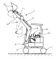
一般に油圧ショベル等の建設機械は、図7に示す如くクローラ本体1の上方に旋回可能なターンテーブル2を備え、ターンテーブル2の上部には操作部3aや運転席3bが搭載され、更にターンテーブル2の前方には作業装置4が配置されている。
In general, a construction machine such as a hydraulic excavator is provided with a
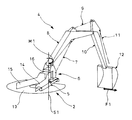
作業装置4は、ターンテーブル2に対してスイングシリンダ5(図8、図10参照)により左右方向へ回動し得るブラケット6と、ブラケット6に対してシリンダ7により上下方向へ回動し得るブーム8と、ブーム8に対してシリンダ9により上下方向へ回動し得るアーム10と、アーム10の先端に対してシリンダ11により上下方向へ回動し得るバケット12を備えている。
The working device 4 includes a
ターンテーブル2は、図8に示す如く板状のベース部13と、ベース部13の軸心両側に位置して延在する第一フレーム縦板14及び第二フレーム縦板15とを備えている。第一フレーム縦板14及び第二フレーム縦板15の前方側には上面フレーム板16及び下面フレーム板17(図12参照)を設け、更に第一フレーム縦板14及び第二フレーム縦板15の先端には筒状の支持部18(図12参照)を設けてピン19を支持し、更にピン19にはブラケット6が固定されている。ここでピン19は、支持部18によって中間位置で支持され且つピン19の軸心が上下方向に向くようになっている。
As shown in FIG. 8, the
ブラケット6は、図9〜図12に示す如く支持部18(図12参照)の上側に配してピン19の上部を固定する上側ピン固定部20と、支持部18の下側に配してピン19の下部を固定する下側ピン固定部21と、支持部18の前方外側に位置して上側ピン固定部20と下側ピン固定部21を固定する側方固定部22と、上側ピン固定部20及び下側ピン固定部21並びに側方固定部22の両側に固定される第一側面部23及び第二側面部24と、下側ピン固定部21に形成されて第一側面部23の外面下部に位置するレバー部25とを備えている。ここで第一側面部23及び第二側面部24は、図11に示す如くブーム8の下端を挟み込むように上方へ延在するブームフート固定部26を備えている。ブームフート固定部26は、上部固定ピン取付孔27を設けて上部固定ピン(図示せず)を配し、上部固定ピンによりブーム8を接続している。また第一側面部23及び第二側面部24の中間位置には、中間側固定ピン取付孔28を設けて中間固定ピン(図示せず)を配し、中間固定ピンによりシリンダ7(図7、図8参照)を接続している。更にレバー部25は、下側固定ピン取付孔29を設けて下部固定ピン(図示せず)を配し、下部固定ピンによりスイングシリンダ5(図8、図9参照)を接続している。なお図10中、符号5aはスイングシリンダ5の後端を接続するスイングシリンダ固定部を示している。
The
またブラケット6の第一側面部23及び第二側面部24の間には、図7〜図9に示す如くシリンダ7,9,11に接続される油圧ホース30(図12参照)が側方固定部22の前面を通るように配置されており、油圧ホース30は、制御弁装置(図示せず)等に接続され、シリンダ7,9,11等を介してブーム8、アーム10、バケット12の回動を制御している。
Further, between the first
更に、このようなスイング構造では、種々の作業において図9に示す如く上側ピン固定部20と下側ピン固定部21の間にトーションバーの如く強い捻りモーメントが発生すると共に、上側ピン固定部20と下側ピン固定部21との間の距離が長く設定されることから第一側面部23、第二側面部24、側方固定部22等の厚みを厚くして剛性を高めている。
Further, in such a swing structure, as shown in FIG. 9, a strong torsional moment like a torsion bar is generated between the upper
ここで上側ピン固定部20と下側ピン固定部21の間にトーションバーの如く強い捻りモーメントが発生する場合を具体的に説明すると、図8に示す如く掘削作業を行う際には、作業の状態や条件によってバケット12の先端に水平横方向に横荷重F1が作用し、更にバケット12の先端からスイング軸S1(ピン19の軸線)までの距離と、横荷重F1の大きさとに応じてブラケット6のブームフート固定部26(ブラケット6の上部)にはスイング軸周りに捻りモーメントM1が作用する。また当該捻りモーメントM1は、図9に示す如く第一側面部23及び第二側面部24に荷重F2,F3を伝達して上側ピン固定部20に捻りモーメントM2を発生させ、ブラケット6を捻り方向へ回転させようとする。この時、スイングシリンダ5のストロークは通常固定されているため、スイングシリンダ5がレバー部25を押すように(荷重F4で示す)、ブラケット6の下部がスイングシリンダ5から反力を受ける状態となり(仮想的な逆方向の捻りモーメントM3で示す)、上側ピン固定部20と下側ピン固定部21の間は、トーションバーの如く強い捻りモーメントが発生する。
Here, the case where a strong torsional moment such as a torsion bar is generated between the upper
また上側ピン固定部20と下側ピン固定部21との間の距離が長くなる理由を具体的に説明すると、ブームフート固定部26の位置は、バケット12の上方での作業や、土砂のすくい上げ作業の際に十分な作業範囲を確保し得るように高い位置で設定されており、一方、レバー部25の位置は、スイングシリンダ5に対応して低い位置で設定されていることから、捻りモーメントM2,M3を受ける上側ピン固定部20と下側ピン固定部21との間の距離が長くなっている。更に上側ピン固定部20及び下側ピン固定部21でターンテーブル2の支持部18(図12参照)を挟み、一本のピン19で締結する場合には、支持部18の剛性を高めるように支持部18の高さを高くするため、捻りモーメントM2,M3を受ける上側ピン固定部20と下側ピン固定部21との間の距離が一層長くなっている。
The reason why the distance between the upper
なお、本発明と関連性が高い建設機械のスイング構造の先行技術文献情報としては、例えば、下記の特許文献1〜3がある。
In addition, as prior art document information of the swing structure of a construction machine highly relevant to the present invention, for example, there are the following
しかしながら、強い捻りモーメントM2,M3等に対応するように第一側面部23、第二側面部24、側方固定部22等の厚みを厚くして剛性を高める場合には、ブラケット6の重量が重くなるという問題があるため、ブラケット6を軽量化する一方で、剛性を一層高めることが求められていた。また油圧ホース30を内部に通すブラケット6は、特許文献1の如く周囲方向の前面を開放し、または特許文献2、3の如く一部に孔を設けて油圧ホース30を配置するため、作業中に発生する飛石等に対して油圧ホース30の保護が十分でないという問題があった。
However, when the thickness of the first
本発明は上述の実情に鑑みてなしたもので、ブラケットを軽量化すると共に剛性を高め、更に油圧ホースの保護を図る建設機械のスイング構造を提供することを目的としている。 The present invention has been made in view of the above-described circumstances, and an object thereof is to provide a swing structure for a construction machine that reduces the weight of the bracket, increases the rigidity, and further protects the hydraulic hose.
本発明は、ターンテーブルにピンを介して左右方向へ回動可能に配置されるブラケットと、該ブラケットに対して上下方向へ回動可能に配置されるブームと、前記ブラケット内を通して配置される油圧ホースとを備える建設機器のスイング構造であって、
前記ブラケットは、前記ピンの上部を固定する上側ピン固定部と、前記ピンの下部を固定する下側ピン固定部と、前記ピンの側部に沿うように形成されて上側ピン固定部と下側ピン固定部を固定する側方固定部と、前記ブームの下端を挟み込むように前記上側ピン固定部及び下側ピン固定部並びに側面部の両側に固定される第一側面部及び第二側面部と、前記側方固定部の前方に位置して第一側面部及び第二側面部に固定される前面部とを備え、
前記前面部、側方固定部、第一側面部、第二側面部は、上側開口及び下側開口を備えて上下方向に油圧ホースを通し得る内部空間を形成し、該内部空間を有する構成は、上側開口から下側開口まで閉断面で構成されたことを特徴とする建設機械のスイング構造にかかるものである。
The present invention relates to a bracket disposed on a turntable so as to be pivotable in the left-right direction via a pin, a boom disposed so as to be pivotable in the vertical direction with respect to the bracket, and a hydraulic pressure disposed through the bracket. A swing structure for construction equipment comprising a hose,
The bracket includes an upper pin fixing portion for fixing the upper portion of the pin, a lower pin fixing portion for fixing the lower portion of the pin, and an upper pin fixing portion and a lower side formed along the side portion of the pin. A side fixing part for fixing the pin fixing part, a first side part and a second side part fixed to both sides of the upper pin fixing part and the lower pin fixing part and the side part so as to sandwich the lower end of the boom; And a front surface portion positioned in front of the side fixing portion and fixed to the first side surface portion and the second side surface portion,
The front surface portion, the side fixing portion, the first side surface portion, and the second side surface portion are provided with an upper opening and a lower opening to form an internal space through which a hydraulic hose can be passed in the up and down direction. The present invention relates to a swing structure for a construction machine, characterized in that it has a closed cross section from an upper opening to a lower opening.
本発明の建設機械のスイング構造において、前面部の下端、第一側面部の下端、第二側面部の下端の少なくとも1つを、下側ピン固定部の下端より下方位置に配することが好ましい。 In the swing structure of the construction machine according to the present invention, it is preferable that at least one of the lower end of the front surface portion, the lower end of the first side surface portion, and the lower end of the second side surface portion is disposed at a position below the lower end of the lower pin fixing portion. .
本発明の建設機械のスイング構造において、前面部の下端からピンの下方まで延在する底部を備えることが好ましい。 In the swing structure for a construction machine according to the present invention, it is preferable that a bottom portion extending from the lower end of the front surface portion to below the pin is provided.
本発明の建設機械のスイング構造によれば、前面部、側方固定部、第一側面部、第二側面部で形成される内部空間が、上側開口から下側開口まで閉断面で構成されるので、側方固定部、第一側面部、第二側面部の厚みを薄くしてブラケットを軽量化すると共に、閉断面で剛性を高めることができる。また前面部、側方固定部、第一側面部、第二側面部で形成される内部空間に、上側開口及び下側開口まで上下方向に油圧ホースを通し、更に上側開口から下側開口までを閉断面に構成するので、油圧ホースを内部に通す内部空間の周囲で油圧ホースが露出することがなく、作業中に発生する飛石等に対して油圧ホースの保護を図ることができるという優れた効果を奏し得る。 According to the swing structure of the construction machine of the present invention, the internal space formed by the front surface portion, the side fixing portion, the first side surface portion, and the second side surface portion is configured with a closed cross section from the upper side opening to the lower side opening. Therefore, the thickness of the side fixing portion, the first side surface portion, and the second side surface portion can be reduced to reduce the weight of the bracket, and the rigidity can be increased with a closed cross section. In addition, a hydraulic hose is passed vertically through the internal space formed by the front surface portion, the side fixing portion, the first side surface portion, and the second side surface portion to the upper opening and the lower opening, and further from the upper opening to the lower opening. Since it has a closed cross section, the hydraulic hose is not exposed around the internal space through which the hydraulic hose passes, and the hydraulic hose can be protected against flying stones generated during work. Can be played.
以下、本発明の実施の形態の第一例を図1〜図3を参照して説明する。なお、図中、図7〜図12と同一の符号を付した部分は同一物を表わしている。 Hereinafter, a first example of an embodiment of the present invention will be described with reference to FIGS. In addition, in the figure, the part which attached | subjected the code | symbol same as FIGS. 7-12 represents the same thing.
実施の形態の第一例の建設機械のスイング構造は、ブラケットの形状を変更したものであり、他の部材は同じ形状、構成を備えている。 The swing structure of the construction machine of the first example of the embodiment is obtained by changing the shape of the bracket, and the other members have the same shape and configuration.
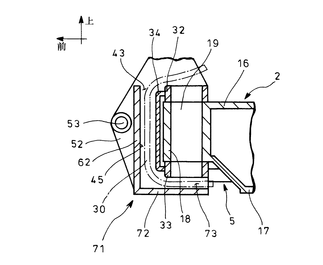
ブラケット31は、支持部18の上部に配する上側ピン固定部32と、支持部18の下部に配する下側ピン固定部33と、ピン19の側部に沿うように形成されて上側ピン固定部32と下側ピン固定部33を固定する側方固定部34と、上側ピン固定部32及び下側ピン固定部33並びに側方固定部34の両側に固定される第一側面部35及び第二側面部36と、下側ピン固定部33に形成されて第一側面部35の外面下部に位置するレバー部37と、側方固定部34の前方に位置して第一側面部35及び第二側面部36に固定される前面部38とを備えている。
The
上側ピン固定部32は、筒状の支持部18と同軸上に筒状の形状を備えてピン19の上部を固定しており、また下側ピン固定部33は、筒状の支持部18と同軸上に筒状の形状を備えてピン19の下部を固定している。
The upper
側方固定部34は、ターンテーブル2と離れた側(前方側)に位置するように支持部18の外側に配置される板材であり、ターンテーブル2とブラケット31の左右方向の回動に悪影響を与えないように構成されている。
The
第一側面部35及び第二側面部36は、ブーム8の下端を挟み込むように上下方向へ延在する板材であり、第一側面部35及び第二側面部36の上端は、ブーム8の回動に干渉しない位置になっていると共に、第一側面部35及び第二側面部36の下端は、下側ピン固定部33の下端と同じ高さで建設機械の作業中に他の構造物と干渉しない位置になっている。また第一側面部35及び第二側面部36は、上部にブームフート固定部39を備えており、ブームフート固定部39は、上部固定ピン取付孔40を設けて上部固定ピン(図示せず)を配し、上部固定ピンによりブーム8を接続している。更に第一側面部35及び第二側面部36の中間位置には、中間側固定ピン取付孔41を設けて中間固定ピン(図示せず)を配し、中間固定ピンによりシリンダ7(図7参照)を接続している。
The first
レバー部37は、下側固定ピン取付孔42を備えて下部固定ピン(図示せず)を配し、下部固定ピンによりスイングシリンダ5を接続している。
The
前面部38は、側方固定部34と中間側固定ピン取付孔41の間に配置される板材であり、前面部38の上端は、上側ピン固定部32の上端と同じ高さに位置してブーム8の回動に干渉しない位置になっていると共に、前面部38の下端は、下側ピン固定部33の下端と同じ高さに位置して建設機械の作業中に他の構造物と干渉しない位置になっている。ここで前面部38は、鉛直方向に沿う形状に限定されるものではなく、上側を前方へ傾斜しても良いし、上側または/及び下側を湾曲しても良い。
The
前面部38、第一側面部35、第二側面部36、側方固定部34、上側ピン固定部32、下側ピン固定部33は、上側開口43及び下側開口44を備える内部空間45を形成し、シリンダ7,9,11(図7参照)等に接続される油圧ホース30を上下方向に通すようにしている。ここで前面部38、第一側面部35、第二側面部36、側方固定部34、上側ピン固定部32、下側ピン固定部33の少なくとも1つには、油圧ホース30を固定するクリップ(図示せず)を備えても良い。
The
また内部空間45を有する構造は、上側ピン固定部32から下側ピン固定部33までの上下の広い範囲を、孔や切欠きのない閉断面とするように、前面部38、第一側面部35、第二側面部36、側方固定部34が構成されており、上側ピン固定部32から下側ピン固定部33までの剛性が高い。また内部空間45に位置する油圧ホース30が外部に露出しないようになっている。
In addition, the structure having the
ここでブラケット31の内部空間45の断面に捻り応力が生じた場合について、内部空間45を有する構造が開断面の場合と、内部空間45を有する構造が閉断面の場合とをモデル化し、数式により比較した。ここで図3では(A)に開断面の場合を示し、(B)に閉断面の場合を示しており、開断面の場合には奥側の厚みt2の部分の捻り応力を算出している。
開断面の場合の捻り応力τは、図3の(A)で材料力学の次式で算出される。
[式1]
τ=3t2・T/(s1・t1 3+s2・t2 3+s3・t3 3)
τ:捻り応力(N/mm2)
T:トルク(Nm)
s1:長さ(mm)
s2:長さ(mm)
s3:長さ(mm)
t1:厚み(mm)
t2:厚み(mm)
t3:厚み(mm)
閉断面の場合の捻り応力τは、図3の(B)で材料力学の次式で算出される。
[式2]
τ=T/{2t・(a−t)(b−t)}
τ:捻り応力(N/mm2)
T:トルク(Nm)
a:長さ(mm)
b:長さ(mm)
t:厚み(mm)
Here, when a torsional stress is generated in the cross section of the
The torsional stress τ in the case of an open section is calculated by the following equation of material mechanics in FIG.
[Formula 1]
τ = 3t 2 · T / (s 1 · t 1 3 + s 2 · t 2 3 + s 3 · t 3 3 )
τ: torsional stress (N / mm 2 )
T: Torque (Nm)
s 1 : Length (mm)
s 2 : Length (mm)
s 3 : Length (mm)
t 1 : thickness (mm)
t 2 : thickness (mm)
t 3 : thickness (mm)
The torsional stress τ in the case of a closed cross section is calculated by the following equation of material mechanics in FIG.
[Formula 2]
τ = T / {2t · (at) (bt)}
τ: torsional stress (N / mm 2 )
T: Torque (Nm)
a: Length (mm)
b: Length (mm)
t: Thickness (mm)
そして内部空間45を有する構造をモデル化した開断面の場合及び閉断面の場合について[表1]のデータにより断面積A及び捻り応力τを算出し、[表1]の下段で結果を示した。なお断面積Aは基本的な面積の数式から算出している。
The cross-sectional area A and the torsional stress τ were calculated from the data in [Table 1] for the open section and the closed section in which the structure having the
[表1]の下段の結果から、断面積Aにおいて開断面の場合は10000mm2に対し、閉断面の場合は4944mm2であり、閉断面の場合は、開断面の場合に比べて重量が約1/2未満になっている。また捻り応力τにおいて開断面の場合は120N/mm2に対し、閉断面の場合は28N/mm2であり、閉断面の場合は、開断面の場合に比べて捻り応力が約1/4未満になっている。よって閉断面の内部空間45を有するブラケット31は、開断面の内部空間45を有するブラケット31よりも軽量化すると共に剛性を高めることが明らかである。また実施の形態例の如く前面部38、第一側面部35、第二側面部36、側方固定部34の側面に孔や切欠きがない場合には強度が高まり、一方、前面部38、第一側面部35、第二側面部36、側方固定部34の側面に孔や切欠きを有する場合には、孔や切欠き部分に応力が集中し、強度が低下することは明らかである。
From the results in the lower part of [Table 1], in the cross-sectional area A, the open cross section is 10000 mm 2 , the closed cross section is 4944 mm 2 , and the closed cross section has a weight that is approximately that of the open cross section. It is less than 1/2. Also with respect to 120 N / mm 2 in the case of open cross-section in twisting stress tau, in the case of closed cross section was 28N / mm 2, in the case of closed section, torsional stress as compared with the opening cross section is less than about 1/4 It has become. Therefore, it is clear that the
而して、実施の形態の第一例によれば、前面部38、側方固定部34、第一側面部35、第二側面部36、上側ピン固定部32、下側ピン固定部33で形成される内部空間45が、上側開口43から下側開口44まで閉断面で構成されるので、側方固定部34、第一側面部35、第二側面部36の厚みを薄くしてブラケット31を軽量化すると共に、剛性を高めることができる。
Thus, according to the first example of the embodiment, the
また前面部38、側方固定部34、第一側面部35、第二側面部36、上側ピン固定部32、下側ピン固定部33で形成される内部空間45に、上側開口43及び下側開口44まで上下方向に油圧ホース30を通し、更に上側開口43から下側開口44までを閉断面に構成するので、油圧ホース30を内部に通す内部空間45の周囲で油圧ホース30が露出することがなく、作業中に発生する飛石等に対して油圧ホース30の保護を図ることができる。
Further, an
更に内部空間45に対して上側開口43及び下側開口44のみを設けるので、油圧ホース30の組付時に油圧ホース30を適切に誘導し、油圧ホース30を容易に設置することができる。
Furthermore, since only the
以下、本発明の実施の形態の第二例を図4を参照して説明する。なお図中、図1〜図3と同一の符号を付した部分は同一物を表わしている。 Hereinafter, a second example of the embodiment of the present invention will be described with reference to FIG. In the figure, the same reference numerals as those in FIGS. 1 to 3 denote the same components.
実施の形態の第二例の建設機械のスイング構造は、第一例のブラケット31の第一側面部35及び第二側面部36の構成を変形したものであり、他の部分は第一例と同じ構成を備えている。
The swing structure of the construction machine of the second example of the embodiment is a modification of the configuration of the first
第二例のブラケット51において第一側面部52及び第二側面部(図示せず)は、ブーム8(図1参照)の下端を挟み込むように上下方向へ延在する板材であり、第一側面部52及び第二側面部の上端は、ブーム8の回動に干渉しない位置になっていると共に、第一側面部52及び第二側面部の下端は、下側ピン固定部33の下端より下方に位置し、建設機械の作業中に他の構造物と干渉しないようになっている。ここで第一側面部52及び第二側面部の下端は、ピン19の下方位置を通過する油圧ホース30を保護し得るように所定の上下幅を備え、下側ピン固定部33の下端からターンテーブル2の下面フレーム板17の下面高さまでの間に位置している。
In the
また第一側面部52及び第二側面部は、上部にブームフート固定部39(図1参照)を備えており、ブームフート固定部39は、上部固定ピン取付孔40(図1参照)を設けて上部固定ピン(図示せず)を配し、上部固定ピンによりブーム8(図1参照)を接続している。更に第一側面部52及び第二側面部の中間位置には、中間側固定ピン取付孔53を設けて中間固定ピン(図示せず)を配し、中間固定ピンによりシリンダ7(図7参照)を接続している。
Further, the first
而して、実施の形態の第二例によれば、第一例と同じ作用効果を得ることができる。 Thus, according to the second example of the embodiment, the same effect as the first example can be obtained.
また実施の形態の第二例において、第一側面部52の下端及び第二側面部の下端を、下側ピン固定部33の下端より下方位置へ配すると、ピン19の下方位置を通過する油圧ホース30を保護し得るので、作業中に発生する飛石に対して油圧ホース30の保護を十分に図ることができる。
In the second example of the embodiment, when the lower end of the first
以下、本発明の実施の形態の第三例を図5を参照して説明する。なお図中、図1〜図4と同一の符号を付した部分は同一物を表わしている。 Hereinafter, a third example of the embodiment of the present invention will be described with reference to FIG. In the figure, the same reference numerals as those in FIGS. 1 to 4 denote the same components.
実施の形態の第三例の建設機械のスイング構造は、第二例の前面部38の構成を変形したものであり、他の部分は第二例と同じ構成を備えている。
The swing structure of the construction machine of the third example of the embodiment is a modification of the configuration of the
第三例のブラケット61において前面部62は、側方固定部34と中間側固定ピン取付孔53の間に配置される板材であり、前面部62の上端は、上側ピン固定部32の上端と同じ高さに位置してブーム8の回動に干渉しないようになっていると共に、前面部62の下端は、下側ピン固定部33の下端より下方に位置して建設機械の作業中に他の構造物と干渉しないようになっている。
In the
ここで前面部62の下端は、ピン19の下方位置を通過する油圧ホース30を保護し得るように所定の上下幅を備え、下側ピン固定部33の下端からターンテーブル2の下面フレーム板17の下面高さまでの間に位置している。なお図5では前面部62の下端を第二例の第一側面部の下端、第二側面部の下端と同じ高さにしている。
Here, the lower end of the
而して、実施の形態の第三例によれば、第一例及び第二例と同じ作用効果を得ることができる。 Thus, according to the third example of the embodiment, the same effects as the first and second examples can be obtained.
また実施の形態の第三例において、前面部62を、下側ピン固定部33の下端より下方位置へ配すると、ピン19の下方位置を通過する油圧ホース30を保護し得るので、作業中に発生する飛石に対して油圧ホース30の保護を十分に図ることができる。
In the third example of the embodiment, when the
以下、本発明の実施の形態の第四例を図6を参照して説明する。なお図中、図1〜図5と同一の符号を付した部分は同一物を表わしている。 A fourth example of the embodiment of the present invention will be described below with reference to FIG. In the figure, the same reference numerals as those in FIGS. 1 to 5 denote the same components.
実施の形態の第四例の建設機械のスイング構造は、第三例のブラケット61の底部の構成を変形したものであり、他の部分は第三例と同じ構成を備えている。
The swing structure of the construction machine of the fourth example of the embodiment is a modification of the configuration of the bottom part of the
第四例のブラケット71において第一側面部52、第二側面部(図示せず)、前面部62の下端には、前面部62の下端からピン19の下方まで延在するように、前面部62の下端から第一側面部52の後端及び第二側面部の後端まで形成される板状の底部72を備えている。またピン19の下端から底部72までの間には、油圧ホース30を配置し得る第二の内部空間73を備え、第二の内部空間73は、前面部62、第一側面部52、第二側面部、側方固定部34で形成される内部空間45に通じている。ここで底部72は、第一側面部52、第二側面部、前面部62に固定しても良いし、着脱可能に構成しても良いし、前面部62、第一側面部52、第二側面部、側方固定部34の構成は内部空間45から第二の内部空間73まで湾曲しても良い。更に下側開口を第二の内部空間73の後端にしても良い。
In the
而して、実施の形態の第四例によれば、第一例〜第三例と同じ作用効果を得ることができる。 Thus, according to the fourth example of the embodiment, the same effects as the first to third examples can be obtained.
また実施の形態の第四例において、前面部62の下端からピン19の下方まで延在する底部72を備えると、ピン19の下方位置を通過する油圧ホース30を一層保護し、更に油圧ホース30が下方へ垂れることを防止するので、油圧ホース30の保護を十分に図ることができる。
Further, in the fourth example of the embodiment, when the
尚、本発明の建設機械のスイング構造は、上述の図示例にのみ限定されるものではなく、建設機器は、ピンを介して回動し得るブラケットを備えるものならば他の建設機器でも良いこと、内部空間の断面は四角形に限定されるものではなく、本発明の作用効果を生じるならば円形、楕円形、他の多角形でも良いこと、その他、本発明の要旨を逸脱しない範囲内において種々変更を加え得ることは勿論である。 It should be noted that the swing structure of the construction machine of the present invention is not limited to the above illustrated example, and the construction equipment may be other construction equipment as long as it has a bracket that can be rotated via a pin. The cross section of the internal space is not limited to a square, and may be a circle, an ellipse, or other polygons as long as the effects of the present invention are produced, and various other modifications may be made without departing from the spirit of the present invention. Of course, changes can be made.
2 ターンテーブル
8 ブーム
9 シリンダ
19 ピン
30 油圧ホース
31 ブラケット
34 側方固定部
35 第一側面部
36 第二側面部
38 前面部
43 上側開口
44 下側開口
45 内部空間
51 ブラケット
52 第一側面部
53 中間側固定ピン取付孔
61 ブラケット
62 前面部
71 ブラケット
72 底部
2
Claims (3)
前記ブラケットは、前記ピンの上部を固定する上側ピン固定部と、前記ピンの下部を固定する下側ピン固定部と、前記ピンの側部に沿うように形成されて上側ピン固定部と下側ピン固定部を固定する側方固定部と、前記ブームの下端を挟み込むように前記上側ピン固定部及び下側ピン固定部並びに側方固定部の両側に固定される第一側面部及び第二側面部と、前記側方固定部の前方に位置して第一側面部及び第二側面部に固定される前面部とを備え、
前記前面部、側方固定部、第一側面部、第二側面部は、上側開口及び下側開口を備えて上下方向に油圧ホースを通し得る内部空間を形成し、該内部空間を有する構造は、上側開口から下側開口まで閉断面で構成されたことを特徴とする建設機械のスイング構造。 A bracket disposed on the turntable via a pin so as to be pivotable in the left-right direction, a boom disposed so as to be pivotable in the vertical direction with respect to the bracket, and a hydraulic hose disposed within the bracket. A swing structure for construction equipment,
The bracket includes an upper pin fixing portion for fixing the upper portion of the pin, a lower pin fixing portion for fixing the lower portion of the pin, and an upper pin fixing portion and a lower side formed along the side portion of the pin. A side fixing portion for fixing the pin fixing portion, a first side surface portion and a second side surface fixed to both sides of the upper pin fixing portion, the lower pin fixing portion, and the side fixing portion so as to sandwich the lower end of the boom. And a front surface portion positioned in front of the side fixing portion and fixed to the first side surface portion and the second side surface portion,
The front surface portion, the side fixing portion, the first side surface portion, and the second side surface portion have an upper opening and a lower opening to form an internal space through which a hydraulic hose can be passed in the vertical direction, and the structure having the internal space is A swing structure for a construction machine, characterized in that it has a closed cross section from an upper opening to a lower opening.
Priority Applications (1)
| Application Number | Priority Date | Filing Date | Title |
|---|---|---|---|
| JP2010155444A JP2012017601A (en) | 2010-07-08 | 2010-07-08 | Swing structure of construction machine |
Applications Claiming Priority (1)
| Application Number | Priority Date | Filing Date | Title |
|---|---|---|---|
| JP2010155444A JP2012017601A (en) | 2010-07-08 | 2010-07-08 | Swing structure of construction machine |
Publications (1)
| Publication Number | Publication Date |
|---|---|
| JP2012017601A true JP2012017601A (en) | 2012-01-26 |
Family
ID=45603043
Family Applications (1)
| Application Number | Title | Priority Date | Filing Date |
|---|---|---|---|
| JP2010155444A Pending JP2012017601A (en) | 2010-07-08 | 2010-07-08 | Swing structure of construction machine |
Country Status (1)
| Country | Link |
|---|---|
| JP (1) | JP2012017601A (en) |
Cited By (1)
| Publication number | Priority date | Publication date | Assignee | Title |
|---|---|---|---|---|
| WO2014181708A1 (en) * | 2013-05-09 | 2014-11-13 | 日立建機株式会社 | Construction equipment |
Citations (3)
| Publication number | Priority date | Publication date | Assignee | Title |
|---|---|---|---|---|
| JP2001032316A (en) * | 1999-07-22 | 2001-02-06 | Kobelco Contstruction Machinery Ltd | Attachment piping structure for hydraulic backhoe |
| JP2005076314A (en) * | 2003-09-01 | 2005-03-24 | Hitachi Constr Mach Co Ltd | Slewing type construction machine |
| JP2005344301A (en) * | 2004-05-31 | 2005-12-15 | Kubota Corp | Swing working machine |
-
2010
- 2010-07-08 JP JP2010155444A patent/JP2012017601A/en active Pending
Patent Citations (3)
| Publication number | Priority date | Publication date | Assignee | Title |
|---|---|---|---|---|
| JP2001032316A (en) * | 1999-07-22 | 2001-02-06 | Kobelco Contstruction Machinery Ltd | Attachment piping structure for hydraulic backhoe |
| JP2005076314A (en) * | 2003-09-01 | 2005-03-24 | Hitachi Constr Mach Co Ltd | Slewing type construction machine |
| JP2005344301A (en) * | 2004-05-31 | 2005-12-15 | Kubota Corp | Swing working machine |
Cited By (3)
| Publication number | Priority date | Publication date | Assignee | Title |
|---|---|---|---|---|
| WO2014181708A1 (en) * | 2013-05-09 | 2014-11-13 | 日立建機株式会社 | Construction equipment |
| JPWO2014181708A1 (en) * | 2013-05-09 | 2017-02-23 | 日立建機株式会社 | Mini excavator |
| US9637888B2 (en) | 2013-05-09 | 2017-05-02 | Hitachi Construction Machinery Co., Ltd. | Construction equipment |
Similar Documents
| Publication | Publication Date | Title |
|---|---|---|
| JP4235186B2 (en) | Loading device for work vehicle | |
| JP4741298B2 (en) | Counterweight device for construction machinery | |
| JP4217687B2 (en) | Piping structure of loader | |
| JP4888739B2 (en) | Wheel loader | |
| JP5789302B2 (en) | Construction machinery | |
| JP2007085036A (en) | Fixing structure of work machine | |
| JP2013087462A (en) | Upper frame of construction machine | |
| JP6262118B2 (en) | Construction machine swivel frame | |
| JP2012017601A (en) | Swing structure of construction machine | |
| JP2018178442A (en) | Work machine | |
| EP1484452A1 (en) | Working vehicle | |
| JP2008201328A (en) | Rear working machine fitting frame structure for tractor | |
| JP5094649B2 (en) | Loader working machine | |
| JPH10331184A (en) | Working machine for hydraulic shovel | |
| JP3927563B2 (en) | Cab and work machine | |
| JP5824414B2 (en) | Construction machinery | |
| JP5119094B2 (en) | Loader working machine | |
| JP2010059681A5 (en) | ||
| JP4214125B2 (en) | Stabilizer | |
| JP5016572B2 (en) | Loader working machine | |
| JP4675925B2 (en) | Tractor frame structure | |
| JP2010059683A5 (en) | ||
| JP6102965B2 (en) | Boom foot part of work machine | |
| JP2010059684A5 (en) | ||
| JP4711867B2 (en) | Work vehicle |
Legal Events
| Date | Code | Title | Description |
|---|---|---|---|
| A621 | Written request for application examination |
Free format text: JAPANESE INTERMEDIATE CODE: A621 Effective date: 20130628 |
|
| A977 | Report on retrieval |
Free format text: JAPANESE INTERMEDIATE CODE: A971007 Effective date: 20131216 |
|
| A131 | Notification of reasons for refusal |
Free format text: JAPANESE INTERMEDIATE CODE: A131 Effective date: 20131224 |
|
| A521 | Written amendment |
Free format text: JAPANESE INTERMEDIATE CODE: A523 Effective date: 20140221 |
|
| A02 | Decision of refusal |
Free format text: JAPANESE INTERMEDIATE CODE: A02 Effective date: 20140422 |