WO2014181478A1 - X-ray device and manufacturing method of structure - Google Patents
X-ray device and manufacturing method of structure Download PDFInfo
- Publication number
- WO2014181478A1 WO2014181478A1 PCT/JP2013/063221 JP2013063221W WO2014181478A1 WO 2014181478 A1 WO2014181478 A1 WO 2014181478A1 JP 2013063221 W JP2013063221 W JP 2013063221W WO 2014181478 A1 WO2014181478 A1 WO 2014181478A1
- Authority
- WO
- WIPO (PCT)
- Prior art keywords
- ray
- guide
- detector
- ray source
- guide surface
- Prior art date
Links
- 238000004519 manufacturing process Methods 0.000 title claims abstract description 25
- 238000001514 detection method Methods 0.000 claims abstract description 216
- 230000003287 optical effect Effects 0.000 claims abstract description 91
- 238000005259 measurement Methods 0.000 claims description 139
- 230000007246 mechanism Effects 0.000 claims description 49
- 238000012360 testing method Methods 0.000 claims description 42
- 238000000034 method Methods 0.000 claims description 32
- 230000008859 change Effects 0.000 claims description 23
- 238000013461 design Methods 0.000 claims description 13
- 230000001678 irradiating effect Effects 0.000 claims description 8
- 230000001105 regulatory effect Effects 0.000 claims description 2
- 238000010586 diagram Methods 0.000 description 48
- 230000004048 modification Effects 0.000 description 28
- 238000012986 modification Methods 0.000 description 28
- 239000000463 material Substances 0.000 description 27
- 239000007788 liquid Substances 0.000 description 21
- 230000007423 decrease Effects 0.000 description 17
- 238000005096 rolling process Methods 0.000 description 14
- XEEYBQQBJWHFJM-UHFFFAOYSA-N Iron Chemical compound [Fe] XEEYBQQBJWHFJM-UHFFFAOYSA-N 0.000 description 12
- 230000005540 biological transmission Effects 0.000 description 10
- 238000006073 displacement reaction Methods 0.000 description 9
- 229910000831 Steel Inorganic materials 0.000 description 8
- 239000010959 steel Substances 0.000 description 8
- 238000007689 inspection Methods 0.000 description 7
- 239000004020 conductor Substances 0.000 description 6
- 238000009434 installation Methods 0.000 description 6
- 229910052742 iron Inorganic materials 0.000 description 6
- 238000003860 storage Methods 0.000 description 6
- 101000744322 Homo sapiens eIF5-mimic protein 1 Proteins 0.000 description 5
- 230000000052 comparative effect Effects 0.000 description 5
- 102100039119 eIF5-mimic protein 1 Human genes 0.000 description 5
- 230000006870 function Effects 0.000 description 5
- 101000802734 Homo sapiens eIF5-mimic protein 2 Proteins 0.000 description 4
- PXHVJJICTQNCMI-UHFFFAOYSA-N Nickel Chemical compound [Ni] PXHVJJICTQNCMI-UHFFFAOYSA-N 0.000 description 4
- 238000004364 calculation method Methods 0.000 description 4
- 238000005266 casting Methods 0.000 description 4
- 102100035859 eIF5-mimic protein 2 Human genes 0.000 description 4
- 230000000694 effects Effects 0.000 description 4
- 230000008569 process Effects 0.000 description 4
- 238000012545 processing Methods 0.000 description 4
- 238000005452 bending Methods 0.000 description 3
- 230000008901 benefit Effects 0.000 description 3
- 230000008878 coupling Effects 0.000 description 3
- 238000010168 coupling process Methods 0.000 description 3
- 238000005859 coupling reaction Methods 0.000 description 3
- 230000002950 deficient Effects 0.000 description 3
- 238000002955 isolation Methods 0.000 description 3
- 239000010935 stainless steel Substances 0.000 description 3
- 229910001220 stainless steel Inorganic materials 0.000 description 3
- 229910000975 Carbon steel Inorganic materials 0.000 description 2
- 229910001374 Invar Inorganic materials 0.000 description 2
- 101100233916 Saccharomyces cerevisiae (strain ATCC 204508 / S288c) KAR5 gene Proteins 0.000 description 2
- 229910045601 alloy Inorganic materials 0.000 description 2
- 239000000956 alloy Substances 0.000 description 2
- 239000010962 carbon steel Substances 0.000 description 2
- 230000008602 contraction Effects 0.000 description 2
- 230000001276 controlling effect Effects 0.000 description 2
- 238000005242 forging Methods 0.000 description 2
- 229910052759 nickel Inorganic materials 0.000 description 2
- 230000008439 repair process Effects 0.000 description 2
- WFKWXMTUELFFGS-UHFFFAOYSA-N tungsten Chemical compound [W] WFKWXMTUELFFGS-UHFFFAOYSA-N 0.000 description 2
- 229910052721 tungsten Inorganic materials 0.000 description 2
- 239000010937 tungsten Substances 0.000 description 2
- 238000004846 x-ray emission Methods 0.000 description 2
- 238000010521 absorption reaction Methods 0.000 description 1
- 230000009471 action Effects 0.000 description 1
- 238000012937 correction Methods 0.000 description 1
- 230000003247 decreasing effect Effects 0.000 description 1
- 230000001066 destructive effect Effects 0.000 description 1
- 230000003670 easy-to-clean Effects 0.000 description 1
- 230000001747 exhibiting effect Effects 0.000 description 1
- 239000004794 expanded polystyrene Substances 0.000 description 1
- 238000002474 experimental method Methods 0.000 description 1
- 230000005484 gravity Effects 0.000 description 1
- 238000002347 injection Methods 0.000 description 1
- 239000007924 injection Substances 0.000 description 1
- 230000009191 jumping Effects 0.000 description 1
- 229910052751 metal Inorganic materials 0.000 description 1
- 239000002184 metal Substances 0.000 description 1
- 238000000465 moulding Methods 0.000 description 1
- 239000004033 plastic Substances 0.000 description 1
- 230000036544 posture Effects 0.000 description 1
- 230000005855 radiation Effects 0.000 description 1
- 230000000630 rising effect Effects 0.000 description 1
- 238000004088 simulation Methods 0.000 description 1
- 239000000126 substance Substances 0.000 description 1
- 229910052715 tantalum Inorganic materials 0.000 description 1
- XLYOFNOQVPJJNP-UHFFFAOYSA-N water Substances O XLYOFNOQVPJJNP-UHFFFAOYSA-N 0.000 description 1
- 229910052726 zirconium Inorganic materials 0.000 description 1
Images


Classifications
-
- G—PHYSICS
- G01—MEASURING; TESTING
- G01N—INVESTIGATING OR ANALYSING MATERIALS BY DETERMINING THEIR CHEMICAL OR PHYSICAL PROPERTIES
- G01N23/00—Investigating or analysing materials by the use of wave or particle radiation, e.g. X-rays or neutrons, not covered by groups G01N3/00 – G01N17/00, G01N21/00 or G01N22/00
- G01N23/02—Investigating or analysing materials by the use of wave or particle radiation, e.g. X-rays or neutrons, not covered by groups G01N3/00 – G01N17/00, G01N21/00 or G01N22/00 by transmitting the radiation through the material
- G01N23/04—Investigating or analysing materials by the use of wave or particle radiation, e.g. X-rays or neutrons, not covered by groups G01N3/00 – G01N17/00, G01N21/00 or G01N22/00 by transmitting the radiation through the material and forming images of the material
- G01N23/046—Investigating or analysing materials by the use of wave or particle radiation, e.g. X-rays or neutrons, not covered by groups G01N3/00 – G01N17/00, G01N21/00 or G01N22/00 by transmitting the radiation through the material and forming images of the material using tomography, e.g. computed tomography [CT]
-
- G—PHYSICS
- G01—MEASURING; TESTING
- G01N—INVESTIGATING OR ANALYSING MATERIALS BY DETERMINING THEIR CHEMICAL OR PHYSICAL PROPERTIES
- G01N23/00—Investigating or analysing materials by the use of wave or particle radiation, e.g. X-rays or neutrons, not covered by groups G01N3/00 – G01N17/00, G01N21/00 or G01N22/00
- G01N23/02—Investigating or analysing materials by the use of wave or particle radiation, e.g. X-rays or neutrons, not covered by groups G01N3/00 – G01N17/00, G01N21/00 or G01N22/00 by transmitting the radiation through the material
- G01N23/04—Investigating or analysing materials by the use of wave or particle radiation, e.g. X-rays or neutrons, not covered by groups G01N3/00 – G01N17/00, G01N21/00 or G01N22/00 by transmitting the radiation through the material and forming images of the material
-
- G—PHYSICS
- G01—MEASURING; TESTING
- G01N—INVESTIGATING OR ANALYSING MATERIALS BY DETERMINING THEIR CHEMICAL OR PHYSICAL PROPERTIES
- G01N23/00—Investigating or analysing materials by the use of wave or particle radiation, e.g. X-rays or neutrons, not covered by groups G01N3/00 – G01N17/00, G01N21/00 or G01N22/00
- G01N23/02—Investigating or analysing materials by the use of wave or particle radiation, e.g. X-rays or neutrons, not covered by groups G01N3/00 – G01N17/00, G01N21/00 or G01N22/00 by transmitting the radiation through the material
- G01N23/06—Investigating or analysing materials by the use of wave or particle radiation, e.g. X-rays or neutrons, not covered by groups G01N3/00 – G01N17/00, G01N21/00 or G01N22/00 by transmitting the radiation through the material and measuring the absorption
- G01N23/083—Investigating or analysing materials by the use of wave or particle radiation, e.g. X-rays or neutrons, not covered by groups G01N3/00 – G01N17/00, G01N21/00 or G01N22/00 by transmitting the radiation through the material and measuring the absorption the radiation being X-rays
- G01N23/087—Investigating or analysing materials by the use of wave or particle radiation, e.g. X-rays or neutrons, not covered by groups G01N3/00 – G01N17/00, G01N21/00 or G01N22/00 by transmitting the radiation through the material and measuring the absorption the radiation being X-rays using polyenergetic X-rays
-
- G—PHYSICS
- G01—MEASURING; TESTING
- G01V—GEOPHYSICS; GRAVITATIONAL MEASUREMENTS; DETECTING MASSES OR OBJECTS; TAGS
- G01V5/00—Prospecting or detecting by the use of ionising radiation, e.g. of natural or induced radioactivity
- G01V5/20—Detecting prohibited goods, e.g. weapons, explosives, hazardous substances, contraband or smuggled objects
- G01V5/22—Active interrogation, i.e. by irradiating objects or goods using external radiation sources, e.g. using gamma rays or cosmic rays
- G01V5/226—Active interrogation, i.e. by irradiating objects or goods using external radiation sources, e.g. using gamma rays or cosmic rays using tomography
-
- G—PHYSICS
- G01—MEASURING; TESTING
- G01V—GEOPHYSICS; GRAVITATIONAL MEASUREMENTS; DETECTING MASSES OR OBJECTS; TAGS
- G01V5/00—Prospecting or detecting by the use of ionising radiation, e.g. of natural or induced radioactivity
- G01V5/20—Detecting prohibited goods, e.g. weapons, explosives, hazardous substances, contraband or smuggled objects
- G01V5/22—Active interrogation, i.e. by irradiating objects or goods using external radiation sources, e.g. using gamma rays or cosmic rays
- G01V5/232—Active interrogation, i.e. by irradiating objects or goods using external radiation sources, e.g. using gamma rays or cosmic rays having relative motion between the source, detector and object other than by conveyor
-
- G—PHYSICS
- G01—MEASURING; TESTING
- G01N—INVESTIGATING OR ANALYSING MATERIALS BY DETERMINING THEIR CHEMICAL OR PHYSICAL PROPERTIES
- G01N2223/00—Investigating materials by wave or particle radiation
- G01N2223/30—Accessories, mechanical or electrical features
- G01N2223/33—Accessories, mechanical or electrical features scanning, i.e. relative motion for measurement of successive object-parts
-
- G—PHYSICS
- G01—MEASURING; TESTING
- G01N—INVESTIGATING OR ANALYSING MATERIALS BY DETERMINING THEIR CHEMICAL OR PHYSICAL PROPERTIES
- G01N2223/00—Investigating materials by wave or particle radiation
- G01N2223/60—Specific applications or type of materials
- G01N2223/646—Specific applications or type of materials flaws, defects
Definitions
- the present invention relates to an X-ray apparatus and a method for manufacturing a structure.
- An X-ray apparatus that irradiates an object with X-rays and detects transmitted X-rays passing through the object as described in the following patent document, for example, as a non-destructive apparatus for acquiring information inside the object.
- An X-ray apparatus that irradiates an object with X-rays and detects transmitted X-rays passing through the object as described in the following patent document, for example, as a non-destructive apparatus for acquiring information inside the object.
- the detection device it is necessary to improve the accuracy of determining the position in the moving direction by the measuring device that measures the position in the moving direction of the table that moves while supporting the object.
- the detection device if the position of the device that guides the table that supports the object and the detection position of the detector that detects the transmitted X-rays transmitted through the object are separated, the positioning accuracy of the measurement position of the table is increased. May be reduced. As a result, the detection accuracy may be reduced.
- An object of the aspect of the present invention is to provide an X-ray apparatus and a structure manufacturing method capable of suppressing a decrease in detection accuracy.
- an X-ray apparatus for irradiating a test object with X-rays and detecting the X-rays passing through the test object, wherein the X-rays are emitted from a light emitting point.
- a source a stage that supports the test object, a detector that detects at least part of transmitted X-rays emitted from the X-ray source and passed through the test object, the light emitting point, and the test object
- a moving device that moves one of the X-ray source, the stage, or the detector as a moving object in a first direction in order to change the distance or at least one of the light emitting point and the detector
- a first measuring device and a second measuring device for measuring the position of the moving object in the first direction, wherein the first measuring device and the second measuring device are movable areas of the moving device
- An X-ray device provided in a second direction intersecting the first direction of It is.
- an X-ray apparatus for irradiating a test object with X-rays and detecting X-rays passing through the object, wherein the X-ray source emits X-rays from a light emitting point; A stage for supporting the test object; a detector for detecting at least part of transmitted X-rays emitted from the X-ray source and passing through the test object; and a distance between the light emitting point and the test object Alternatively, in order to change the distance between at least one of the light emitting point and the detector, at least one movement of the X-ray source, the stage, and the detector is defined by a guide surface that is a plane, and the movement is guided.
- An X-ray apparatus comprising: a guide device, wherein the plane including the guide surface and parallel to the guide surface is disposed in a region where transmitted X-rays passing through the test object are detected by the detector. Is provided.
- an X-ray apparatus for irradiating a test object with X-rays and detecting X-rays passing through the test object, wherein the X-rays are emitted from a light emitting point.
- a source a stage that supports the test object, a detector that detects at least a portion of transmitted X-rays emitted from the X-ray source and passed through the test object, the X-ray source, the stage, and the detection
- a guide device for guiding movement in a direction parallel to an axis connecting the light emitting point and a center of a light receiving surface on which the detector receives the X-ray, at least one of the detectors, the X-ray source, Including a guide surface that is a plane that regulates the movement of the stage and the detector, and a plane parallel to the guide surface is near an axis that connects the light emitting point and the center of the light receiving surface on which the detector receives the X-rays An X-ray device is provided.
- design information relating to the shape of a structure is created, the structure is created based on the design information, and the created structure is used as the object.
- a structure manufacturing method is provided in which the shape of a structure is measured using the X-ray apparatus described above, and the shape information obtained by the measurement is compared with the design information.
- FIG. 1 is a diagram illustrating an example of an apparatus according to an embodiment.
- FIG. 2 is a perspective view illustrating an example of a support body included in the apparatus according to the embodiment.
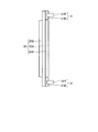
- FIG. 3 is a side view showing a first side wall of the support shown in FIG.
- FIG. 4 is a side view showing a second side wall of the support shown in FIG.
- FIG. 5 is a bottom view illustrating an example of a support body included in the apparatus according to the embodiment.
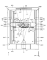
- 6 is an AA arrow view of FIG.
- FIG. 7 is a top view of the detection device.
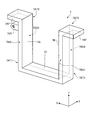
- FIG. 8 is a perspective view showing a table support provided in the detection device.
- FIG. 9 is a diagram for explaining a structure for moving in the direction of the table rotation axis.
- FIG. 9 is a diagram for explaining a structure for moving in the direction of the table rotation axis.
- FIG. 10 is a diagram for explaining a structure for moving in the direction of the table rotation axis.
- FIG. 11 is a diagram illustrating a second movable member that supports the table.
- FIG. 12 is a diagram showing a counterweight.
- FIG. 13 is a diagram for explaining a guide surface of the guide device.
- FIG. 14 is a view for explaining a guide surface of the guide device.
- FIG. 15 is a diagram for explaining a guide surface of the guide device.
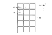
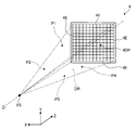
- FIG. 16 is a diagram illustrating a detection area.
- FIG. 17 is a diagram illustrating a detection area.
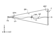
- FIG. 18 is a diagram illustrating the relationship between the detection area and the guide surface.
- FIG. 19 is a diagram illustrating the relationship between the detection region and the guide surface in the comparative example.
- FIG. 19 is a diagram illustrating the relationship between the detection region and the guide surface in the comparative example.
- FIG. 20 is a diagram illustrating a relationship between the detection area and the guide surface in the present embodiment.
- FIG. 21 is a diagram illustrating the relationship between the detection region and the guide surface in the present embodiment.
- FIG. 22 is a diagram illustrating a modification of the relationship between the detection region and the guide surface in the present embodiment.
- FIG. 23 is a diagram showing a modification of the table support.
- FIG. 24 is a diagram showing a modification of the table support.
- FIG. 25 is a diagram showing a modification of the table support.
- FIG. 26 is a diagram illustrating a modification of the arrangement of the first guide device and the second guide device.
- FIG. 27 is a diagram illustrating a detection device according to a modification of the embodiment.
- FIG. 28 is a diagram illustrating a detection device according to a modified example of the embodiment.
- FIG. 29 is a diagram illustrating a detection device according to a modification of the embodiment.
- FIG. 30 is a sectional view showing an example of the X-ray source according to the present embodiment.
- FIG. 31 is a flowchart for explaining an example of the operation of the detection apparatus according to the embodiment.
- FIG. 32 is a diagram for explaining an example of the operation of the detection device according to the embodiment.
- FIG. 33 is a diagram for explaining an example of the operation of the detection device according to the embodiment.
- FIG. 34 is a flowchart illustrating an example of a procedure for measuring the shape or the like of the measurement object using the detection apparatus according to the embodiment.
- FIG. 35 is a diagram illustrating an example of a procedure for measuring the shape or the like of the measurement object using the detection device according to the embodiment.
- FIG. 36 is a diagram illustrating an example of a procedure for measuring the shape or the like of the measurement object using the detection device according to the embodiment.
- FIG. 37 is a diagram illustrating an example of a procedure for measuring the shape or the like of the measurement object using the detection apparatus according to the embodiment.
- FIG. 38 is a diagram illustrating an example of a structure manufacturing system including the detection device according to the embodiment.
- FIG. 39 is a flowchart showing the flow of processing by the structure manufacturing system.
- FIG. 40 is a diagram illustrating a detection device according to a modified example of the embodiment.
- an XYZ orthogonal coordinate system is set, and the positional relationship of each part will be described with reference to this XYZ orthogonal coordinate system.
- a predetermined direction in the horizontal plane is defined as the Z-axis direction
- a direction orthogonal to the Z-axis direction in the horizontal plane is defined as the X-axis direction
- a direction orthogonal to each of the Z-axis direction and the X-axis direction is defined as the Y-axis direction.
- the rotation (inclination) directions around the X, Y, and Z axes are the ⁇ X, ⁇ Y, and ⁇ Z directions, respectively.
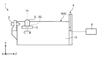
- FIG. 1 is a diagram illustrating an example of an apparatus according to an embodiment.
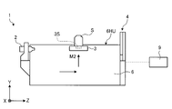
- FIG. 2 is a perspective view illustrating an example of a support body included in the apparatus according to the embodiment.
- FIG. 3 is a side view showing a first side wall of the support shown in FIG.
- FIG. 4 is a side view showing a second side wall of the support shown in FIG.
- FIG. 5 is a bottom view illustrating an example of a support body included in the apparatus according to the embodiment.
- the detection apparatus 1 as an X-ray apparatus according to the present embodiment irradiates a measurement object S as a test object with an X-ray XL, and detects transmitted X-rays transmitted through the measurement object S.
- X-rays are electromagnetic waves having a wavelength of about 1 pm to about 30 nm, for example.
- the X-ray includes at least one of an ultra soft X-ray of about 50 eV, a soft X-ray of about 0.1 keV to 2 keV, an X-ray of about 2 keV to 20 keV, and a hard X-ray of about 20 keV to 100 keV.
- the detection device 1 irradiates the measurement object S with X-rays, detects transmitted X-rays transmitted through the measurement object S, and information inside the measurement object S (for example, internal structure).
- X-ray CT inspection device that acquires non-destructively.
- the device under test S includes industrial parts such as mechanical parts or electronic parts.
- the X-ray CT inspection apparatus includes an industrial X-ray CT inspection apparatus that irradiates industrial parts with X-rays and inspects the industrial parts.
- a detection apparatus 1 includes an X-ray source 2 that emits X-rays XL, a table 3 as a stage that supports a measurement object S, and an object that is emitted from the X-ray source 2 and supported by the table 3.
- a detector 4 that detects at least part of transmitted X-rays that have passed through the measurement object S, and a guide device 5 that supports movement of the table 3 in a direction parallel to the optical axis of the X-ray XL while supporting the table 3; including.
- the direction parallel to the optical axis of the X-ray XL is the Z-axis direction.
- the table 3 is supported by the table support 7.
- the table 3 only needs to have a function of supporting the object to be measured S, and further includes a mechanism that moves in at least one of the X axis direction, the Y axis direction, the Z axis direction, the ⁇ X direction, the ⁇ Y direction, and the ⁇ Z direction. You may have.
- the guide device 5 guides the movement of the table support 7 in a direction parallel to the optical axis of the X-ray XL. With such a structure, the table 3 is guided by the guide device 5 via the table support 7 and moves in a direction parallel to the optical axis of the X-ray XL.
- the detection device 1 has a support 6 to which the X-ray source 2, the detector 4, and the guide device 5 are attached.
- the X-ray source 2, the detector 4 and the guide device 5 are supported by the same support body 6.
- the X-ray source 2, the detector 4, and the guide device 5 move in the same manner together with the support 6, so that these postures are compared with the case where they are attached to separate structures.
- the change in the positional relationship when it changes can be reduced.
- the detection device 1 can suppress a decrease in detection accuracy due to a change in the positional relationship among the X-ray source 2, the detector 4, and the guide device 5.
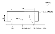
- the support 6 has a first side wall 6SA as a first support member, a second side wall 6SB as a second support member, and a bottom 6B as a third support member.
- the first side wall 6SA and the second side wall 6SB include a third side wall 6SC as a fourth support member provided on the first end portions 6SA1 and 6SB1 side, and the second end portions 6SA2 and 6SB2 side.
- a fourth side wall 6SD as a fifth support member provided in the first and second support members.
- the first side wall 6SA, the second side wall 6SB, the third side wall 6SC, and the fourth side wall 6SD are plate-like or wall-like portions rising from the bottom portion 6B that is a plate-like portion.
- first side wall 6SA, the second side wall 6SB, the third side wall 6SC, and the fourth side wall 6SD rise from the corners of the bottom 6B that is rectangular as shown in FIG.
- the first side wall 6SA, the second side wall 6SB, the third side wall 6SC, the fourth side wall 6SD, and the bottom part 6B are all rectangular when viewed from directions orthogonal to these wall surfaces.
- the first side wall 6SA and the second side wall 6SB are opposed to each other and the wall surfaces are parallel to each other.
- the third side wall 6SC and the fourth side wall 6SD face each other, and the wall surfaces are parallel.
- the wall surface of the first sidewall 6SA and the wall surface of the second sidewall 6SB are orthogonal to the wall surface of the third sidewall 6SC and the wall surface of the fourth sidewall 6SD.
- 3rd side wall 6SC has 1st convex part 6SCX which protrudes toward the direction away from self, as shown in FIG.2, FIG3 and FIG.4. Similar to the third side wall 6SC, the fourth side wall 6SD has a second convex portion 6SDD protruding in a direction away from the fourth side wall 6SD.
- an X-ray source support member 2S that supports the X-ray source 2 is attached to the first convex portion 6SCX.
- a detector support member 4S that supports the detector 4 is attached to the second convex portion 6SDD.
- the X-ray source 2 is attached to the first end portions 6SA1 and 6SB1 of the first side wall 6SA and the second side wall 6SB.
- the detector 4 is attached to the second end portions 6SA2 and 6SB2 side of the first side wall 6SA and the second side wall 6SB.
- the first side wall 6SA, the second side wall 6SB, the third side wall 6SC, the fourth side wall 6SD, and the bottom 6B are thicker than the other parts (dimensions in the direction perpendicular to the plate surface).
- the thinned portion 6G has a rectangular shape.
- the thickness of 6R between adjacent thinning portions 6G is larger than the thinning portions 6G and larger than the dimensions of the adjacent thinning portions 6G.
- the 6R between the adjacent thinned portions 6G are the ribs of the first side wall 6SA, the second side wall 6SB, the third side wall 6SC, the fourth side wall 6SD, and the bottom 6B.
- 6R between adjacent thinned portions 6G is appropriately referred to as a rib 6R.
- the support body 6 has the first side wall 6SA, the second side wall 6SB, the third side wall 6SC, the fourth side wall 6SD, and the bottom part 6B, the increase in mass can be suppressed. Further, since the first side wall 6SA, the second side wall 6SB, the third side wall 6SC, the fourth side wall 6SD, and the bottom part 6B have the ribs 6R, the support body 6 also suppresses a decrease in strength due to having the plurality of lightening parts 6G. can do.
- the support 6 is made of a material having a small linear expansion coefficient.
- a material having a small linear expansion coefficient for example, an alloy called invariable steel (invar or super invar) obtained by adding 36% nickel to iron can be used. Such materials are generally expensive.
- invariable steel invar or super invar
- the amount of the material used for the support 6 can be reduced. For this reason, when the expensive material with a small linear expansion coefficient is used for the support body 6, when the support body 6 has the several lightening part 6G, the increase in the manufacturing cost of the support body 6 will be suppressed.
- the X-ray source 2, the detector 4, and the guide device 5 are attached to the support 6.
- the table 3 that supports the object to be measured S is supported by the support 6 via the table support 7 and the guide device 5. Since the support 6 is made of a material having a small coefficient of linear expansion, even when the temperature around the support 6 rises during measurement of the shape of the object S to be measured by the detection device 1, the support 6 is Changes in dimensions due to temperature are suppressed. As a result, a change in the relative positional relationship among the X-ray source 2, the detector 4, the guide device 5, and the table 3 due to the thermal expansion of the support 6 is suppressed to a minimum. For this reason, the detection apparatus 1 can suppress that measurement accuracy, such as the shape of the to-be-measured object S, falls to the minimum.
- the first side wall 6SA, the second side wall 6SB, the third side wall 6SC, the fourth side wall 6SD, and the bottom 6B are manufactured as an integral structure by, for example, casting.
- the support body 6 can be manufactured easily.
- the support body 6 may be produced by a manufacturing method other than casting.
- 1st side wall 6SA and 2nd side wall 6SB have the several through-hole 6H penetrated in the direction orthogonal to a wall surface, as shown in FIG.2, FIG3 and FIG.4.
- the respective through holes 6H are provided at different positions on the wall surfaces of the first side wall 6SA and the second side wall 6SB, more specifically at different positions in the Y-axis direction and the Z-axis direction.
- the plurality of through holes 6H are provided at different positions in the Y-axis direction and the Z-axis direction, different positions of the internal space SP can be easily accessed using different through-holes 6H. For this reason, even if the devices included in the detection device 1 are arranged at different positions in the space 6SP, it is easy to easily clean and maintain the devices described above.
- the detection apparatus 1 is housed in a chamber member 8 that forms an internal space SP in which the X-ray XL emitted from the X-ray source 2 travels.
- the detection device 1 is disposed in the internal space SP.
- the detection apparatus 1 includes a supply port 26 that supplies a temperature-adjusted gas G to at least a part of the X-ray source 2. The supply port 26 is disposed in the internal space SP.
- the support body 6 has a plurality of legs 6F.
- the plurality of legs 6F are attached to the bottom 6B of the support 6 shown in FIG.
- the legs 6F are in contact with the bottom 8B of the chamber member 8.
- the lower surface of the support 6, that is, the surface facing the bottom portion 8 ⁇ / b> B of the chamber member 8 and the bottom portion 8 ⁇ / b> B of the chamber member 8 are separated by the legs 6 ⁇ / b> F. That is, a space is formed between the lower surface of the support 6 and the bottom 8 ⁇ / b> B of the chamber member 8.
- at least a part of the lower surface of the support 6 and the bottom 8B of the chamber member 8 may be in contact with each other.
- the bottom 6B of the support 6 is disposed on the bottom 8B side of the chamber member 8 to be installed. That is, the bottom 6 ⁇ / b> B is the installation side of the detection device 1.
- the detection device 1 places the support 6 on the bottom 8B of the chamber member 8, but the installation method of the support 6 is not limited to this.
- the support 6 may be suspended from the installation target using a rope or the like.
- the plurality of legs 6 ⁇ / b> F of the support 6 are provided with a vibration isolation mechanism for suppressing vibration from the outside of the detection device 1 from being transmitted to the X-ray source 2 through the chamber member 8, for example.
- the vibration isolation mechanism uses, for example, an air spring or a spring formed of metal. Further, the vibration isolation mechanism may not be used for all of the plurality of legs 6F.
- the chamber member 8 is installed on the support surface FR.
- the support surface FR includes a floor surface of a factory or the like.
- the chamber member 8 is supported by a plurality of legs 8S.
- the chamber member 8 is disposed on the support surface FR via the legs 8S.
- the lower surface of the chamber member 8 and the support surface FR are separated by the legs 8S. That is, a space is formed between the lower surface of the chamber member 8 and the support surface FR.
- the chamber member 8 contains lead.
- the chamber member 8 suppresses the X-ray XL in the internal space SP from leaking into the external space RP of the chamber member 8.
- the chamber member 8 has a member having a lower thermal conductivity than the chamber member 8.
- the chamber member 8 has a member having a lower thermal conductivity than the chamber member 8.
- this member is disposed on the outer surface of the chamber member 8. This member suppresses the temperature of the internal space SP from being affected by the temperature (temperature change) of the external space RP. That is, this member functions as a heat insulating member that suppresses the heat of the external space RP from being transmitted to the internal space SP.
- This member includes, for example, plastic.
- this member contains, for example, expanded polystyrene or iron. For example, iron may be disposed inside the chamber member.
- the strength of the chamber member 8 can be reinforced.
- the chamber member 8 and the iron member may be in direct contact, or at least a part of the chamber member 8 and the iron member may be in contact.
- the X-ray source 2 irradiates the measurement object S with X-ray XL.
- the X-ray source 2 includes an emission unit 2E that emits X-ray XL.
- the X-ray source 2 forms a point X-ray source.
- the emission unit 2E includes a point X-ray source.
- the X-ray source 2 irradiates the object S to be measured with conical X-rays (so-called cone beam).
- the X-ray source 2 may be capable of adjusting the intensity of the emitted X-ray XL.
- the intensity of the X-ray XL emitted from the X-ray source 2 may be adjusted based on the X-ray absorption characteristics of the object to be measured S or the like.
- the shape of the X-rays emitted from the X-ray source 2 is not limited to a conical shape, and may be, for example, a fan-shaped X-ray (so-called fan beam).
- the injection part 2E faces the + Z direction.
- the + Z direction is a direction from the X-ray source 2 toward the detector 4.
- at least a part of the X-ray XL emitted from the emission unit 2E proceeds in the + Z direction in the internal space SP.
- the supply port 26 supplies the temperature-adjusted gas G to at least a part of the X-ray source 2.
- the detection device 1 includes an adjustment device 25 that adjusts the temperature of the gas G.
- the adjusting device 25 is operated by electric power, for example.
- the supply port 26 supplies the gas G from the adjustment device 25 to the internal space SP.
- the adjusting device 25 is disposed in the external space RP of the chamber member 8.
- the adjusting device 25 is installed on the support surface FR.
- the adjusting device 25 is connected to the conduit 26P.
- the conduit 26 ⁇ / b> P connects the adjustment device 25 and the internal space SP of the chamber member 8.
- the conduit 26P opens into the internal space SP of the chamber member 8. This opening functions as a supply port 26 for supplying the gas G to the internal space SP.
- the adjustment device 25 adjusts the temperature of the gas, for example, by taking the gas in the external space RP.
- the gas G whose temperature has been adjusted by the adjusting device 25 is sent to the supply port 26 through the conduit 26P.
- the supply port 26 is disposed so as to face at least a part of the X-ray source 2.
- the supply port 26 supplies the gas G from the adjustment device 25 to at least a part of the X-ray source 2.
- the detector 4 is arranged on the + Z side from the X-ray source 2 and the table 3 in the internal space SP.
- the detector 4 faces the emission part 2E of the X-ray source 2.
- the position of the detector 4 is fixed at a predetermined position.
- the detector 4 may be movable.
- the table 3 can move between the X-ray source 2 and the detector 4 in the internal space SP.
- the detector 4 includes a scintillator unit 36 having an incident surface 4DP on which an X-ray XL from the X-ray source 2 including transmitted X-rays transmitted through the object S to be measured, and a light reception unit that receives light generated in the scintillator unit 36. Part 37.
- the incident surface 4DP of the detector 4 faces the object to be measured S supported by the table 3.
- the incident surface 4DP is a surface on which the X-rays of the detector 4 are incident.
- at least one of the X-ray XL irradiated from the X-ray source 2 and the transmitted X-ray irradiated from the X-ray source 2 and transmitted through the measurement object S is incident on the incident surface 4DP.
- the scintillator unit 36 includes a scintillation substance that generates light having a wavelength different from that of the X-ray when irradiated with the X-ray XL.
- the light receiving unit 37 includes a photomultiplier tube.
- the photomultiplier tube includes a phototube that converts light energy into electrical energy by a photoelectric effect.
- the light receiving unit 37 amplifies the light generated in the scintillator unit 36, converts it into an electrical signal, and outputs it.
- the detector 4 has a plurality of scintillator sections 36. A plurality of scintillator sections 36 are arranged in the XY plane. The scintillator portions 36 are arranged in an array.
- the detector 4 includes a plurality of light receiving units 37 so as to be connected to each of the plurality of scintillator units 36. The detector 4 may convert incident X-rays directly into electrical signals without converting them into light.
- the operation of the detection device 1 is controlled by the control device 9.
- the control device 9 controls the operation of the X-ray source 2, calculates the shape of the measurement object S from the result of the detector 4 detecting the transmitted X-ray transmitted through the measurement object S, or the table 3.
- the operation of the adjusting device 25 is controlled.
- the control device 9 is, for example, a computer.
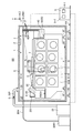
- FIG. 6 is a view taken along arrow AA in FIG.
- FIG. 7 is a top view of the detection device.
- FIG. 8 is a perspective view showing a table support provided in the detection device.
- Reference sign Zr shown in FIGS. 6 and 7 indicates the optical axis of the X-ray source 2. In the present embodiment, the optical axis Zr is parallel to the Z axis. The same applies to the following examples.
- the table 3 is supported by the table body 3B.
- the table 3 includes a support mechanism (also referred to as an object support mechanism) 3S for supporting the measurement object S.
- the support mechanism 3S is, for example, a system that sucks an object to be supported by negative pressure.
- the support mechanism 3S is not limited to the suction method, and may be a method of sandwiching an object to be supported by a member, for example.
- the table 3 is provided with a support mechanism 3S, and a surface on which the support mechanism 3S supports the object S to be measured is a support surface 3P.
- the optical axis of the X-ray source 2 is a line connecting the light emitting point of X-rays generated by the X-ray source 2 and the centers of the plurality of light receiving portions 37 of the detector 4.
- the center of the plurality of light receiving portions 37 of the detector 4 is a point where the respective center lines in the X-axis direction and the Y-axis direction intersect in FIG.
- the table body 3B supports the table 3 and is fixed to the attachment target of the table 3.
- the table body 3B includes a rotation driving device 3D for rotating around an axis Yr orthogonal to the support surface 3P of the table 3.
- the axis Yr orthogonal to the support surface 3P of the table 3 is also referred to as a table rotation axis Yr as appropriate in the following. Since the table rotation axis Yr is an axis parallel to the Y axis, the table 3 rotates in the ⁇ Y direction.
- the rotational drive device 3D includes, for example, an electric motor, and rotates the table 3 by the rotational force of the electric motor.
- the table 3 includes a rotary encoder 10 for measuring the rotation amount (position in the ⁇ Y direction) of the table 3.
- the rotary encoder 10 includes, for example, a scale member 10S provided on the table body 3B and an encoder head 10E provided on the table 3 and detecting the scale of the scale member 10S. With such a structure, the rotary encoder 10 measures the amount of rotation of the table 3 relative to the table body 3B.
- the control device 9 illustrated in FIG. 1 controls the rotation amount of the table 3 by controlling the operation of the rotation driving device 3D based on the rotation amount of the table 3 measured by the rotary encoder 10, for example.
- the table body 3 ⁇ / b> B is attached to the first movable member 11.
- the first movable member 11 is supported by a rail 13 ⁇ / b> R as a guide member attached to the base 12.
- the base 12 is attached to the second movable member 14.
- the second movable member 14 is attached to the table support 7 via a guide mechanism 15 provided between the table support 7 and the second movable member 14.
- the table 3 is supported by the table support 7 via the table body 3B, the first movable member 11, the rail 13R, the base 12, the second movable member 14, and the guide mechanism 15. ing.
- the base 12 includes a plurality of (two in the present embodiment) rails 13 ⁇ / b> R and 13 ⁇ / b> R arranged substantially in parallel at a predetermined interval on the first movable member 11 side. Yes.
- the two rails 13R and 13R extend in the X-axis direction.
- the first movable member 11 is guided by the rails 13R and 13R and moves in the X-axis direction along the rails 13R and 13R.
- the screw shaft 16 is screwed in the nut which self has.
- the screw shaft 16 is attached to the output shaft of the actuator 17.
- the actuator 17 is an electric motor.
- the actuator 17 rotates the screw shaft 16.
- the screw shaft 16 is rotatably supported by bearings 18A and 18B supported on the base 12. In the present embodiment, the screw shaft 16 is supported by the bearings 18A and 18B so that its own axis and the X-axis are substantially parallel.
- the screw shaft 16 When the actuator 17 rotates, the screw shaft 16 also rotates. Since the screw shaft 16 is screwed into a nut included in the first movable member 11, when the screw shaft 16 rotates, the first movable member 11 moves in the X-axis direction.
- a ball is disposed between the nut of the first movable member 11 and the screw shaft 16. That is, the first movable member 11 moves in the X-axis direction by the ball screw mechanism. At this time, as described above, the two rails 13R and 13R guide the movement of the first movable member 11 in the X-axis direction.
- the movement amount (position in the X-axis direction) of the first movable member 11 is detected by the linear encoder 19.
- the linear encoder 19 includes an encoder head 19E and a linear scale 19S.
- the linear scale 19 ⁇ / b> S is attached to the first movable member 11 side of the base 12.
- the encoder head 19E is attached at a position facing the linear scale 19S of the first movable member 11.
- the linear encoder 19 measures the amount of movement of the first movable member 11 with respect to the base 12 in the X-axis direction.
- the control device 9 shown in FIG. 1 controls the movement amount of the first movable member 11 by controlling the operation of the actuator 17 based on the movement amount of the first movable member 11 measured by the linear encoder 19, for example. That is, the control device 9 controls the movement amount of the table 3 in the X-axis direction based on the movement amount of the first movable member 11 measured by the linear encoder 19.
- the second movable member 14 to which the base 12 is attached is attached to the table support 7 via a plurality of (two in this embodiment) guide mechanisms 15, 15. It is supported.
- the guide mechanism 15 includes a rail 15R as a guide member and a moving body 15M.
- the moving body 15M is attached to the rail 15R, and the rail 15R guides the movement in the direction in which the rail 15R extends.
- the second movable member 14 can move in a direction orthogonal to the support surface 3 ⁇ / b> P of the table 3.
- the rail 15R is attached to the table support 7.
- the table support 7 includes a first member 7A, a second member 7B, and a third member 7C.
- the first member 7A is disposed on the first side wall 6SA side of the support 6.
- the second member 7B is disposed on the second side wall 6SB side of the support 6.
- the third member 7C connects the first end 7AT1 of the first member 7A and the first end 7BT1 of the second member 7B.
- the first member 7A, the second member 7B, and the third member 7C are all plate-like members. The plate surfaces of the first member 7A and the second member 7B face each other.
- 1st member 7A, 2nd member 7B, and 3rd member 7C are arrange
- the first member 7A, the second member 7B, and the third member 7C are arranged outside the incident surface 4DP of the detector 4.
- the table support 7 can avoid interference with the detection region DR, so that the entire detection region DR of the detection apparatus 1 is effectively used.
- the detection area DR will be described later.
- the table support 7 is manufactured as an integrated structure of the first member 7A, the second member 7B, and the third member 7C by a manufacturing method such as casting or forging. By doing in this way, the table support body 7 can be produced easily. Further, the table support 7 manufactured as an integral structure by the manufacturing method described above, the first member 7A, the second member 7B, and the third member 7C are manufactured as separate parts, and fastening members such as bolts are used. The rigidity and strength can be increased as compared with the case of being manufactured by using and integrating. The table support 7 is not excluded from being manufactured by a manufacturing method other than casting or forging.
- the table support 7 is made of a material (for example, invariant steel) having a small linear expansion coefficient, like the support 6 described above.
- the material having a small linear expansion coefficient is as described above. Since the table support 7 is made of a material having a small linear expansion coefficient, even if the temperature around the table support 7 rises during measurement of the shape of the object S to be measured by the detection device 1, the table support 7 7, the change of the dimension by temperature is suppressed. As a result, the positional deviation of the measurement object S due to the thermal expansion of the table support 7 is suppressed to the minimum. For this reason, the detection apparatus 1 can suppress that measurement accuracy, such as the shape of the to-be-measured object S, falls to the minimum.
- One of the two rails 15R, 15R is attached to the side portion 7AS1 of the first member 7A of the table support 7.
- the other rail 15R is attached to the side portion 7BS1 of the second member 7B of the table support 7.
- the side part 7AS1 of the first member 7A and the side part 7BS1 of the second member 7B are side parts on the X-ray source 2 side.
- the two rails 15R and 15R are not the side portions 7AS1 and 7AS2 on the X-ray source 2 side, but the side portion 7AS2 on the detector 4 side of the first member 7A and the detector 4 on the second member 7B shown in FIG. It may be attached to the side part 7BS2.
- the rail 15R attached to the first member 7A and the rail 15R attached to the second member 7B are arranged substantially in parallel.
- the two rails 15R and 15R extend in the Y-axis direction.
- the second movable member 14 includes moving bodies 15M and 15M that are attached to and guided by the rails 15R and 15R. With such a structure, the second movable member 14 is guided to the rails 15R and 15R via the moving bodies 15M and 15M, and moves in the Y-axis direction along the rails 15R and 15R.
- the second movable member 14 has a screw shaft 20 screwed into a nut that the second movable member 14 has.
- the screw shaft 20 is attached to the output shaft of the actuator 21.
- the actuator 21 and the screw shaft 20 are moving mechanisms that move the table 3 in parallel with a direction orthogonal to the support surface 3P of the table 3 on which the detection object S is supported.
- the actuator 21 is an electric motor.
- the actuator 21 rotates the screw shaft 20.
- the screw shaft 20 is rotatably supported by the table support 7, more specifically, bearings 22 ⁇ / b> A and 22 ⁇ / b> B supported by the first member 7 ⁇ / b> A of the table support 7.
- the screw shaft 20 is supported by the bearings 22A and 22B so that its own axis and the Y-axis are substantially parallel.
- the screw shaft 20 When the actuator 21 rotates, the screw shaft 20 also rotates. Since the screw shaft 20 is screwed into a nut included in the second movable member 14, when the screw shaft 20 rotates, the second movable member 14 moves in the Y-axis direction.
- a ball is disposed between the nut included in the second movable member 14 and the screw shaft 20. That is, the second movable member 14 moves in the Y-axis direction by the ball screw mechanism. At this time, as described above, the two rails 15R and 15R guide the movement of the second movable member 14 in the Y-axis direction.
- the table support 7 includes a plurality (two in this embodiment) of linear encoders 23A and 23B.
- the number of linear encoders 23A and 23B included in the table support 7 is not limited, and may be one or three or more.
- the movement amount (position in the Y-axis direction) of the second movable member 14 is detected by at least one of the linear encoder 23A and the linear encoder 23B.
- the linear encoder 23A includes an encoder head 23AE and a linear scale 23AS as a first scale.
- the linear encoder 23B includes an encoder head 23BE and a linear scale 23BS as a second scale.
- the linear scale 23AS is attached to the side portion 7AS1 of the first member 7A of the table support 7.
- the linear scale 23BS is attached to the side portion 7BS1 of the second member 7B of the table support 7.
- the linear scale 23AS can also be used to measure the length of the first member 7A, and the linear scale 23BS can also be used to measure the length of the second member 7B.
- the encoder head 23AE is the base 12 supported by the second movable member, and is attached at a position facing the linear scale 23AS attached to the first member 7A.
- the encoder head 23BE is the base 12 supported by the second movable member, and is attached at a position facing the linear scale 23BS attached to the second member 7B.
- the linear encoders 23A and 23B measure the amount of movement of the base 12 and the second movable member 14 with respect to the table support 7 in the Y-axis direction.
- the control device 9 shown in FIG. 1 controls the operation of the actuator 21 based on the amount of movement of the base 12 and the second movable member 14 measured by at least one of the linear encoder 23A and the linear encoder 23B, for example.
- control device 9 controls the movement amount of the table 3 in the Y-axis direction based on the movement amounts of the base 12 and the second movable member 14 measured by the linear encoder 23A and the like.
- At least one of the two linear encoders 23A and 23B included in the table support 7 is a length in the Y-axis direction of at least one of the first member 7A and the second member 7B of the table support 7.
- the linear scale 23AS measures the length of the first member 7A, specifically, the length in the Y-axis direction
- the linear scale 23BS is the length of the second member 7B, specifically, the length in the Y-axis direction. Used to measure the thickness.
- the length in the Y-axis direction is a length in a direction parallel to the table rotation axis Yr.
- the lengths of the first member 7A and the second member 7B in the Y-axis direction vary depending on the mass of the measurement object S supported by the table 3. For this reason, the 1st member by the to-be-measured object S is measured by measuring the length in the Y-axis direction of at least one of the 1st member 7A and the 2nd member 7B when the table 3 is supporting the to-be-measured object S.
- the elongation in the Y-axis direction of 7A and the second member 7B (elongation toward the bottom portion 6B of the support 6) is required.
- the control device 9 operates the actuator 21 to move the table 3 in the direction opposite to the bottom portion 6B of the support 6 by the above-described elongation measured by at least one of the two linear encoders 23A and 23B. .
- the measurement object S itself can be corrected.
- the detection apparatus 1 can suppress a decrease in measurement accuracy such as the shape of the object S to be measured.
- one of the two linear encoders 23A and 23B determines the length of the first member 7A or the second member 7B in the Y-axis direction. Just measure.
- the inclination of the table 3 around the Z-axis is obtained by using both linear encoders 23A and 23B. Is required.
- the control device 9 By using the measurement values of the two linear encoders 23A and 23B, the control device 9 more accurately obtains the displacement of the position of the measurement object S in the Y-axis direction due to the mass of the measurement object S itself, The position of the table 3 in the Y-axis direction can be controlled. As a result, the detection apparatus 1 can suppress a decrease in measurement accuracy such as the shape of the object S to be measured.
- the tilt of the table 3 around the Z axis can be obtained by using both of the two linear encoders 23A and 23B. (Inclination of the table 3 with respect to the XY plane) is obtained.
- the control device 9 more accurately obtains the displacement of the position of the measurement object S in the Y-axis direction due to the mass of the measurement object S itself, The position of the table 3 in the Y-axis direction can be controlled. As a result, the control device 9 can accurately control the position of the measurement object S in the Y-axis direction.
- the detection device 1 includes the linear encoders 23A and 23B on the first member 7A and the second member 7B of the table support body 7, respectively, and the control device 9 determines the Y of the table 3 based on the measurement results of both. More preferably, the position in the axial direction is controlled or corrected.
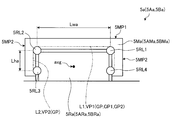
- the table support 7 is interposed via a first guide device 5 ⁇ / b> A that is a part of the guide device 5 shown in FIG. 1 and a second guide device 5 ⁇ / b> B that is also a part of the guide device 5.
- the first guide device 5A includes a rail 5AR as a guide member and a moving body 5AM that is guided in a direction in which the rail 5AR extends.
- the second guide device 5B includes a rail 5BR as a guide member and a moving body 5BM guided in a direction in which the rail 5BR extends.
- the table support 7 includes a first flange portion 7AF on the second end 7AT2 side opposite to the third member 7C of the first member 7A, and a third member 7C of the second member 7B.
- a second flange portion 7BF is provided at the second end portion 7BT2 opposite to the first end portion 7BT2.
- the first flange portion 7AF extends from the end portion 7AT2 of the first member 7A in the opposite direction to the second member 7B and projects in the X-axis direction.
- the second flange portion 7BF extends from the end portion 7BT2 of the second member 7B in the opposite direction to the first member 7A and protrudes in the X-axis direction.
- the first flange portion 7AF extends to a position overlapping the end surface 6SAT of the first side wall 6SA on the side opposite to the bottom 6B of the support 6,
- the second flange portion 7BF extends to a position overlapping the end surface 6SBT of the second side wall 6SB on the side opposite to the bottom portion 6B of the support 6.
- the end surface 6SAT of the first side wall 6SA and the bottom portion 6B of the support 6 are connected to the wall portion 6SW of the first side wall 6SA.
- the end 6SBT of the second side wall 6SB and the bottom 6B of the support 6 are connected to the wall 6SW of the second side wall 6SB.
- the wall portion 6SW rises in a direction substantially orthogonal to the bottom surface 6BI as a surface of the bottom portion 6B on the first side wall 6SA and the second side wall 6SB side. Note that the rib 6R rises from the wall surface of the wall 6SW in a direction substantially perpendicular to the wall surface.
- the rail 5AR of the first guide device 5A is attached to the end surface 6SAT of the first side wall 6SA.
- the rail 5BR of the second guide device 5B is attached to the end surface 6SBT of the second side wall 6SB.
- the end surface 6SAT of the first side wall 6SA and the end surface 6SBT of the second side wall 6SB are disposed with the optical axis Zr interposed therebetween. That is, the end surface 6SAT of the first side wall 6SA and the end surface 6SBT of the second side wall 6SB are arranged on both sides of the optical axis Zr.
- the first guide device 5A in which the rail 5AR is attached to the end surface 6SAT of the first side wall 6SA and the second guide device 5B in which the rail 5BR is attached to the end surface 6SBT of the second side wall 6SB are on both sides of the optical axis Zr. Be placed. Further, as shown in FIG. 6, in the present embodiment, the first guide device 5A and the second guide device 5B are arranged outside the detection region DR.
- the first guide device 5A is disposed between the first flange portion 7AF of the table support 7 and the end surface 6SAT of the first side wall 6SA.
- the second guide device 5B is disposed between the second flange portion 7BF of the table support 7 and the end surface 6SBT of the second side wall 6SB.
- the first member 7A and the second member 7B extend from the first guide device 5A and the second guide device 5B toward the installation side of the detection device 1, that is, toward the bottom 6B of the support body 6.
- the third member 7C connects the installation side of the first member 7A and the second member 7B, that is, the bottom 6B side of the support 6.
- the table support 7 is supported by the support 6 at two locations in the direction in which the third member 7C extends, that is, in the direction from the first member 7A to the second member 7B or in the opposite direction. That is, the table support body 7 is attached to and supported by the support body 6 by a both-end support structure. For this reason, the table support body 7 can make the bending with respect to a load small compared with the case where it is supported by the support body 6 with a cantilever structure. Since the table support 7 supports the table 3 that supports the object to be measured S, the deflection of the table support 7 with respect to the load is reduced, so that the displacement of the object S supported by the table 3 is also reduced. be able to. As a result, the detection apparatus 1 can suppress a decrease in detection accuracy.
- the rail 5AR of the first guide device 5A is provided at a position overlapping the wall 6SW of the first side wall 6SA.
- the rail 5BR of the second guide device 5B is provided at a position overlapping the wall 6SW of the second side wall 6SB.
- a rib 6R rises from the wall 6SW of the bottom 6B in a direction substantially perpendicular to the wall surface.
- the rib 6R of the bottom portion 6B, the wall portion SW of the first side wall 6SA, and the wall portion 6SW of the second side wall 6SB are provided at positions overlapping the wall portion 6SW of the bottom portion 6B.
- the rib 6R of the bottom 6B disposed on the opposite side of the side wall 6SA and the second side wall 6SB is minimized. As a result, the position shift in the Y-axis direction of the first guide device 5A and the second guide device 5B is suppressed.
- the rail 5AR of the first guide device 5A and the rail 5BR of the second guide device 5B extend in a direction parallel to the optical axis Zr.
- the moving body 5AM of the first guide device 5A is combined with the rail 5AR, and its movement is guided by the rail 5AR.
- the moving body 5BM of the second guide device 5B is combined with the rail 5BR, and its movement is guided by the rail 5BR. That is, the moving body 5AM and the moving body 5BM are guided in a direction parallel to the optical axis Zr by the rail 5AR and the rail 5BR.
- the moving body 5AM of the first guide device 5A is attached to the surface 7AFP on the third member 7C side.
- 2nd flange part 7BF provided in the 2nd member 7B of the table support body 7 the mobile body 5BM of the 2nd guide apparatus 5B is attached to the surface 7BFP by the side of the 3rd member 7C. Since the rails 5AR and 5BR of the first guide device 5A and the second guide device 5B are attached to the support body 6 as described above, the table support body 7 is interposed via the first guide device 5A and the second guide device 5B. Attached to the support 6.
- the first member 7A of the table support 7 is guided to move parallel to the optical axis Zr by the first guide device 5A.
- the movement of the second member 7B of the table support 7 parallel to the optical axis Zr is guided by the second guide device 5B.
- the table support 7 can be moved in a direction parallel to the optical axis Zr by the first guide device 5A and the second guide device 5B.
- the table 3 is attached to the table support 7 via the first movable member 11 and the second movable member 14. For this reason, the table 3 is attached to the support 6 via the table support 7.
- the table 3 can be moved in a direction parallel to the optical axis Zr by the first guide device 5A and the second guide device 5B via the table support 7. That is, the first guide device 5A is arranged outside the detection region DR and guides the movement of the table 3 in a direction parallel to the optical axis Zr while supporting the table 3.
- the second guide device 5B is disposed outside the detection region DR and at a position different from the first guide device 5A, and guides the movement of the table 3 in a direction parallel to the optical axis Zr while supporting the table 3.
- the first guide device 5A has a first guide surface GP1 that is parallel to the optical axis Zr and is a plane that defines at least one movement of the X-ray source 2, the table 3, and the detector 4. .
- the second guide device 5B has a second guide surface GP2 that is parallel to the optical axis Zr and is a plane that defines at least one movement of the X-ray source 2, the table 3, and the detector 4.
- at least one of the X-ray source 2 and the detector 4 may be movable. In this case, the movement of at least one of the X-ray source 2 and the detector 4 may be guided by the first guide device 5A and the second guide device 5B.
- the guide surface GP passes through the transmission X-ray detection region DR of the detector 4. .
- the guide surface GP passes through the detection region DR in a direction orthogonal to the support surface 3P of the table 3 on which the measurement object S is supported.
- the guide surface GP is a plane parallel to and including the first guide surface GP1 and the second guide surface GP2.
- the guide surface GP is a plane that defines the movement of the table 3. The guide surface GP will be described later.
- the table support 7 has a screw shaft 27 screwed into a nut 7NT that the table support 7 has.
- the nut 7NT is provided on the first member 7A of the table support 7 as shown in FIGS. 6 and 8, but the nut 7NT is provided on the second member 7B or the third member 7C. May be.
- the screw shaft 27 is attached to the output shaft of the actuator 28 shown in FIG.
- the actuator 28 is an electric motor.
- the actuator 28 rotates the screw shaft 27.
- the screw shaft 27 is rotatably supported by the support body 6, more specifically, bearings 29A and 29B supported by the first side wall 6SA of the support body 6.
- the screw shaft 27 is supported by the bearings 29A and 29B so that its own axis and the optical axis Zr are substantially parallel.
- the screw shaft 27 When the actuator 28 rotates, the screw shaft 27 also rotates. Since the screw shaft 27 is screwed into a nut 7NT included in the table support 7, the table support 7 moves in the optical axis Zr direction when the screw shaft 27 rotates.
- a ball is disposed between the nut 7NT included in the table support 7 and the screw shaft 27. That is, the table support 7 is moved in the direction of the optical axis Zr by the ball screw mechanism. At this time, as described above, the two rails 5AR and 5BR guide the movement of the table support 7 in the direction of the optical axis Zr.
- the support 6 includes a plurality (two in this embodiment) of linear encoders 24A and 24B.
- the number of linear encoders 24A and 24B included in the support 6 is not limited, and may be one or three or more.
- the movement amount (position in the optical axis Zr direction) of the table support 7 is detected by at least one of the linear encoder 24A and the linear encoder 24B.
- the linear encoder 24A includes an encoder head 24AE and a linear scale 24AS.
- the linear encoder 24B includes an encoder head 24BE and a linear scale 24BS.
- the linear scale 24AS as the first scale and the linear scale 24B as the second scale have patterns arranged in the first direction (the optical axis Zr direction in the present embodiment).
- the linear scale 24AS is fixed to the end surface 6SAT of the first side wall 6SA of the support body 6.
- the linear scale 24BS as the second scale is fixed to the end surface 6SBT of the second side wall 6SB of the support 6.
- the encoder head 24AE as the first measuring device detects the pattern of the linear scale 24AS and measures the position of the table support 7 as the moving object in the first direction (in the present embodiment, the optical axis Zr direction).
- the encoder head 24BE as the second measuring device detects the pattern of the linear scale 24BS and measures the position of the table support 7 as the moving device in the first direction.
- the encoder heads 24AE and 24BE are arranged in a second direction (X-axis direction in the present embodiment) that intersects the first direction (optical axis Zr direction in the present embodiment) in the movable region of the moving device. Is done.
- the encoder head 24AE is attached to the side surface 7AFS of the first flange portion 7AF of the table support 7 that is opposite to the second flange portion 7BF.
- the encoder head 24BE is attached to a side surface 7BFS of the second flange portion 7BF of the table support 7 that is opposite to the first flange portion 7AF.
- the encoder heads 24AE and 24BE are supported by the table support 7 serving as a moving device.
- the encoder heads 24AE and 24BE are arranged with the optical axis Zr interposed therebetween.
- the two linear encoders 24A and 24B are arranged on both sides of the optical axis Zr and outside the detection region DR. That is, the two linear encoders 24A and 24B are arranged on the outer side and both sides of the detection region DR.
- Linear encoders 24A and 24B measure the amount of movement of the table support 7 with respect to the support 6 in the optical axis Zr direction.
- the control device 9 shown in FIG. 1 controls the operation of the actuator 28 based on the amount of movement of the table support 7 measured by at least one of the linear encoder 24A and the linear encoder 24B, for example, and the amount of movement of the table support 7 To control. That is, the control device 9 controls the amount of movement of the table 3 in the optical axis Zr direction based on the amount of movement of the table support 7 measured by the linear encoder 24A and the like.
- the position of the table 3 can be controlled by accurately obtaining the deviation.
- the control device 9 can accurately control the position of the device under test S in the optical axis Zr direction.
- the detection apparatus 1 includes the linear encoders 24A and 24B on both sides of the optical axis Zr, and the control apparatus 9 controls the position of the table 3 in the optical axis Zr direction based on the measurement results of both. preferable.
- FIGS. 9 and 10 are diagrams for explaining a structure for moving in the direction of the table rotation axis.
- the table 3 and the table main body 3B are supported by the table support 7 via the first movable member 11, the base 12, and the second movable member 14. Since the second movable member 14 is supported by the side portion 7AS1 of the first member 7A of the table support body 7 and the side portion 7BS1 of the second member 7B via the guide mechanism 15, the table 3 is the first member. It moves along 7A and the second member 7B.
- the table 3 includes a table main body 3B, a first movable member 11, a nut 11NT that is attached to the first movable member 11 and into which the screw shaft 16 is screwed, a base 12, a rail 13R, and a moving body 13M.
- the table support 7 includes a counterweight 30 in order to reduce the load of the actuator 21 shown in FIG.
- the counterweight 30 is disposed on the side portions 7AS2 and 7BS2 opposite to the side portions 7AS1 and 7BS1 of the first member 7A and the second member 7B.
- the counterweight 30 is attached to the first member 7A and the second member 7B via guide mechanisms 31 and 31 attached to the side portions 7AS2 and 7BS2 of the first member 7A and the second member 7B, respectively.
- Rails 31R and 31R as guide members provided in the guide mechanism 31 are attached to the side portion 7AS2 of the first member 7A and the side portion 7BS2 of the second member 7B, respectively.
- the rails 31R, 31R are the first member 7A and the second member in the direction in which the first member 7A and the second member 7B extend, that is, from the first flange portion 7AF and the second flange portion 7BF toward the third member 7C. It extends along 7B.
- the moving bodies 31M and 31M guided in combination with the rails 31R and 31R are attached to the counterweight 30. With such a structure, the counterweight 30 is guided by the guide mechanisms 31 and 31 and moves along the first member 7A and the second member 7B.
- the XY movement mechanism STxy and the counterweight 30 are connected by a rope 32. As shown in FIG. 10, the rope 32 passes through the second flange portion 7BF side of the second member 7B and connects the XY movement mechanism STxy and the counterweight 30. Two pulleys 33A and 33B and a pulley support 33C that supports them are attached to the second flange portion 7BF of the second member 7B. The pulleys 33A and 33B are attached to the pulley support 33C by shafts 33SA and 33SB, respectively. A rope 32 connecting the XY moving mechanism STxy and the counterweight 30 is wound around pulleys 33A and 33B.
- the mass of the counterweight 30 and the mass of the XY moving mechanism STxy are approximately the same. For this reason, the XY movement mechanism STxy and the counterweight 30 which are arranged on the side portions 7AS1 and 7BS1 side and the side portions 7AS2 and 7BS2 side of the first member 7A and the second member 7B, respectively, and connected by the rope 32, are , The mass is balanced. Therefore, when the XY moving mechanism STxy is moved in the Y-axis direction, it can be moved with a small force. As a result, since the power for moving the XY movement mechanism STxy is reduced, the load on the actuator 21 shown in FIG. 6 is reduced. In addition, since less power is required to move the XY moving mechanism STxy, it is possible to use a small actuator with a small output.
- FIG. 11 is a diagram showing a second movable member that supports the table.
- the second movable member 14 that supports the table 3 is a plate-like member that moves along the first member 7 ⁇ / b> A and the second member 7 ⁇ / b> B of the table support 7.
- the second movable member 14 includes a first plate-like member 14A and second plate-like members 14B and 14B.
- the moving bodies 15M and 15M of the guide mechanisms 15 and 15 are attached to the first plate member 14A.
- the rails 15R and 15R of the guide mechanisms 15 and 15 are attached to the first member 7A and the second member 7B, respectively. That is, the first plate-like member 14A is attached to the first member 7A and the second member 7B via the guide mechanisms 15 and 15.
- the first plate-like member 14A moves along the first member 7A and the second member 7B by the guide mechanisms 15 and 15.
- the first plate member 14A is made of a material having a small linear expansion coefficient (invariant steel in the present embodiment), like the support 6 and the table support 7. As previously mentioned, such materials are expensive. For this reason, in this embodiment, in order to reduce the usage amount of the material having a small linear expansion coefficient, the second plate shape made of a material different from that of the first plate member 14A is used for the first plate member 14A.
- the member 14B is combined to form the second movable member 14. Specifically, a pair of first plate members 14A, that is, two second plate members 14B and 14B are attached to both surfaces of the first plate member 14A. Accordingly, the pair of second plate members 14B and 14B sandwich the first plate member 14A from both surfaces.
- the second plate-like members 14B and 14B are made of a steel material such as carbon steel or stainless steel. Such a steel material is less expensive than a nickel-based alloy that is the material of the first plate-like member 14A. Moreover, such a steel material has high strength and rigidity. Therefore, even if the thickness of the second plate members 14B and 14B is reduced by using a steel material such as carbon steel or stainless steel for the second plate members 14B and 14B, the second movable member 14 is required. It becomes easy to ensure strength and rigidity.
- the material of the second plate-like members 14B and 14B has a linear expansion coefficient different from that of the first plate-like member 14A. Specifically, the material of the second plate members 14B and 14B has a larger linear expansion coefficient than the material of the first plate member 14A.
- the second plate member 14B may be attached to one surface of the first plate member 14A. However, since there is a difference in linear expansion coefficient between the first plate-like member 14A and the second plate-like member 14B, the second plate-like member 14B having a larger linear expansion coefficient than the first plate-like member 14A is changed to the first plate-like shape. When attached to one surface of the member 14A, the second movable member 14 may be warped due to a change in temperature.
- the second plate-like members 14B and 14B are attached to both surfaces of the first plate-like member 14A, respectively.
- the warp (deformation) of the second movable member 14 due to a change in temperature is suppressed, and the positional deviation of the table 3 and the measurement object S supported by the table 3 is suppressed.
- the pair of second plate-like members 14B and 14B are preferably made of the same material. Furthermore, it is preferable that the pair of second plate-like members 14B and 14B have the same shape and dimensions. If it does in this way, since expansion and contraction of the 2nd plate-like members 14B and 14B resulting from the change of temperature in the both surface sides of the 1st plate-like member 14A can be made substantially the same, the curvature of the 2nd movable member 14 ( Deformation) can be further suppressed.
- FIG. 12 is a diagram showing a counterweight.
- the counterweight 30 has a structure in which a pair of two plate-like members 30B, that is, two second plate-like members 30B are sandwiched on both surfaces of the first plate-like member 30A.
- a moving body 31M guided by the rail 31R of the guide mechanism 31 is attached to the first plate-like member 30A.
- the first plate-like member 30A is made of a material having a low linear expansion coefficient (invariant steel in this embodiment). Has been.
- the entire counterweight 30 is made of a material having a small linear expansion coefficient, the manufacturing cost of the counterweight 30 increases.
- the 2nd plate-shaped member 30B produced with the material cheaper than this is attached to 30A of 1st plate-shaped members.
- the first plate member 30A by sandwiching the first plate member 30A with a pair of second plate members 30B, 30B made of the same material, the second plate shape on both surfaces of the first plate member 30A.
- the deformation of the member 30B can be made the same. As a result, it is possible to suppress warping (deformation) of the counterweight 30 due to a change in temperature while exhibiting the function of the counterweight 30.
- the manufacturing cost of the counterweight 30 can be suppressed.
- the pair of second plate-like members 30B and 30B have the same shape and dimensions. In this way, the expansion and contraction of the second plate members 30B and 30B caused by the temperature change on both sides of the first plate member 30A can be further made the same, so that the counterweight 30 warps ( Deformation) can be further suppressed.
- FIG. 13, FIG. 14 and FIG. 15 are diagrams for explaining the guide surface of the guide device. 13 and 14 show a cross section (hereinafter, referred to as a transverse cross section as appropriate) taken along a plane orthogonal to the moving direction of the moving bodies 5M and 5Ma, that is, the direction in which the rails 5R and 5Ra extend.
- the guide device 5 that guides the movement of the table 3 supported by the table support 7 shown in FIGS. 6, 7 and 8 in the direction of the optical axis Zr, that is, the first guide device 5A and the second guide.
- the device 5b has a first guide surface gp1 and a second guide surface gp2, respectively, as shown in FIGS.
- the first guide surface gp1 and the second guide surface gp2 are planes that define the movement of the moving bodies 5AM and 5BM.
- both the first guide device 5A and the second guide device 5B guide the movement of the table 3 via the table support 7 shown in FIGS. 6 and 7, etc.
- the first guide surface gp1 and the second guide surface gp2 And a plane that defines the movement of the table 3 (the same applies hereinafter).
- the rail 5R (5AR, 5BR) and the moving body 5M (5AM, 5BM) are in contact with each other.
- the guide device 5 has two contact surfaces SR1 and SR2 between the moving body 5M and the rail 5R.
- the contact area between the moving body 5M and the rail 5R is larger on the contact surface SR1 than on the contact surface SR2. For this reason, the contact length Lw of the contact surface SR1 in the cross section is larger than the contact length Lh of the contact surface SR2 (Lw> Lh).
- the moving body 5M is tilted around an axis axg parallel to the moving direction of the moving body 5M, that is, the direction in which the rail 5R extends (hereinafter referred to as a guide axis as appropriate).
- the effect of suppressing the inclination is that the contact surface SR1 whose contact length Lw in the cross section is larger than the contact length Lh of the contact surface SR2 is larger than the contact surface SR2.
- the guide surface GP, the first guide surface GP1, and the second guide surface GP2 of the guide device 5, the first guide device 5A, and the second guide device 5B are movable bodies 5M, 5AM, and 5BM around the guide axis axg. It is assumed that the contact surface SR1 has a larger effect of suppressing the inclination of the contact surface SR1.
- the guide device 5a shown in FIG. 14, that is, the first guide device 5Aa and the second guide device 5Ba, are rolling elements (balls in this example) between the rail 5Ra (5ARa, 5BRa) and the moving body 5Ma (5AMa, 5BMa). 5RL1, 5RL2, 5RL3, and 5RL4 are interposed.
- the moving body 5Ma is guided to the rail 5Ra via the rolling elements 5RL1, 5RL2, 5RL3, and 5RL4.
- the rail 5Ra has a substantially rectangular cross section.
- a rolling element 5RL1 and a rolling element 5RL2 are provided adjacent to the long side of the rail 5Ra.
- the rolling element 5RL2 and the rolling element 5RL3 are provided adjacent to each other on the short side of the rail 5Ra, and the rolling element 5RL1 and the rolling element 5RL4 are provided adjacent to each other.
- a line segment L1 that connects the portion closest to the first surface 5MP1 is considered.
- a plane formed by developing this line segment L1 parallel to the guide axis axg is defined as a plane VP1.
- a contact portion between the rolling element 5RL2 (or the rolling element 5RL1) and the moving body 5Ma, and a portion closest to the narrow surface (hereinafter referred to as a second surface as appropriate) 5MP2 of the moving body 5Ma Then, consider a line segment L2 that is a contact portion between the rolling element 5RL3 (or the rolling element 5RL4) and the moving body 5Ma and connects the portion closest to the second surface 5MP2.
- a plane formed by developing this line segment L2 parallel to the guide axis axg is defined as a plane VP2.
- the plane VP1 and the plane VP2 are surfaces on which the rail 5Ra defines the movement of the moving body 5Ma.
- the plane VP1 has a larger area than the plane VP2.
- the length of the plane VP1 in the cross section ie, the length Lwa of the line segment L1 is larger than the length of the plane VP2 in the cross section, ie, the length Lha of the line segment L2 (Lwa> Lha).
- the moving body 5Ma is tilted around the guide axis axg of the guide device 5a.
- the effect of suppressing the inclination is that the plane VP1 in which the contact length Lwa in the cross section is larger than the contact length Lha of the plane VP2 is larger than the plane VP2.
- the guide surface GP, the first guide surface GP1, and the second guide surface GP2 of the guide device 5a, the first guide device 5Aa, and the second guide device 5Ba suppress the inclination of the moving body 5Ma around the guide axis axg. It is assumed that the plane VP1 having the larger action is referred to.
- the guide device 5b shown in FIG. 15 has two contact surfaces SR1 and SR2 arranged in parallel and opposite to each other.
- the contact surfaces SR1 and SR2 are surfaces on which the rail 5Rb and the moving body 5Mb are in contact.
- the first surface 5MP1, which is the wider surface of the moving body 5Mb, is a surface on the contact surfaces SR1, SR2 side.
- the second surface 5MP2 that is the narrower surface of the moving body 5Mb is a surface that connects the pair of first surfaces 5MP1 and 5MP1.
- a structure is attached to the second surface 5MP2.
- the guide surface GP is a plane parallel to the two contact surfaces SR1 and SR2 and present at the same distance from the contact surfaces SR1 and SR2. is there.
- the distances from the respective contact surfaces SR1, SR2 to the guide surface GP are all Lh / 2.
- the guide surface GP passes through the guide axis axg.
- the guide surface GP passes through the detection region DR in a direction orthogonal to the support surface 3P of the table 3 on which the object to be measured S is supported.
- the support surface 3P of the table 3 is orthogonal to the vertical direction, that is, the direction in which gravity acts.
- the first guide device 5A and the second guide device 5B are preferable because the rails 5AR and 5BR and the moving bodies 5AM and 5BM can receive the load described above at a portion where they overlap in a larger area.
- FIG. 16 and 17 are diagrams showing detection areas.
- FIG. 16 shows the detection region DR when the incident surface 4DP of the detector 4 is rectangular (including a square).
- FIG. 17 shows the detection region DRa when the incident surface 4DPa of the detector 4a is circular.
- the detection region DR is a light emitting region (focal point) XS of the X-ray source 2 shown in FIG. 1 and the outer edge of the incident surface 4DP where the detector 4 receives X-rays.
- This is a region surrounded by the surfaces P1, P2, P3, and P4 formed by connecting 4E and the incident surface 4DP.
- the detection region DR is a quadrangular pyramid having the incident surface 4DP as a bottom surface and the light emitting region XS as a vertex.
- the detection region DRa is an incident surface on which the light emitting region XS of the X-ray source 2 and the detector 4a shown in FIG. This is a region surrounded by the surface Pa formed by connecting the outer edges 4Ea of 4DPa and the incident surface 4DPa.
- the detection region DRa is a cone having the incident surface 4DPa as a bottom surface and the light emitting region XS as a vertex.
- the incident surface 4DP may be a polygon other than a rectangle, for example, a polygon such as a triangle or a hexagon, and the incident surface 4DPa may be an ellipse other than a circle.
- FIG. 18 is a diagram showing the relationship between the detection area and the guide surface.
- the first guide device 5A and the second guide device 5B are arranged with the optical axis Zr interposed therebetween, and support the substantially U-shaped table support 7 on the support 6.
- the guide surface GP is a plane that passes through at least a part of the first guide surface GP1 of the first guide device 5A and at least a part of the second guide surface GP2 of the second guide device 5B.
- the first guide surface GP1 and the second guide surface GP2 are set to the same position in the table rotation axis Yr direction or the Y-axis direction.
- the guide surface GP is a plane parallel to and including the first guide surface GP1 of the first guide device 5A and the second guide surface GP2 of the second guide device 5B. That is, the guide surface GP is a plane that passes through all of the first guide surface GP1 and the second guide surface GP2.
- the first guide surface GP1 and the second guide surface GP2 are as described with reference to FIGS.
- the guide surface GP (or a plane including the guide surface GP and parallel to the guide surface GP) passes through the detection region DR of transmitted X-rays of the detector 4, and further the optical axis Zr. And parallel to the optical axis Zr.
- the guide surface GP only needs to pass through the detection region DR. If this condition is satisfied, the optical axis Zr may not be included like the guide surface GPa shown in FIG. 18, or may not be parallel to the optical axis Zr like the guide surface GPb.
- FIG. 19 is a diagram showing the relationship between the detection area and the guide surface in the comparative example.
- FIG. 20 is a diagram illustrating a relationship between the detection area and the guide surface in the present embodiment.
- Reference symbols DPH and DPL in FIGS. 19 and 20 are detection centers of the incident surface 4DP of the detector 4.
- the detection centers DPH and DPL exist on the optical axis Zr.
- the distance (shortest distance) from the guide surface GP to the detection center DPH is LH
- the distance (shortest distance) from the guide surface GP to the detection center DPL is LL.
- the guide surface GP is arranged outside the detection region DR, and the two do not intersect. In the present embodiment, the guide surface GP passes through the detection region DR. In the present embodiment, the guide surface GP is further disposed so as to include the optical axis Zr and be parallel to the optical axis Zr. 18 and 19 show the guide surface GP in an enlarged manner.
- the guide surface GP is defined by the surfaces of the rails 5AR and 5BR provided in the first guide device 5A and the second guide device 5B on the moving body 5AM and 5BM side. The surfaces of the rails 5AR and 5BR may not have the dimensions and shape as designed due to processing errors and the like.
- the guide surface GP defined by the surfaces of the rails 5AR and 5BR is macroscopically flat but not microscopically flat. Therefore, as shown in FIGS. 19 and 20, the guide surface GP is microscopically different in position in the Y-axis direction in the Z-axis direction.
- the guide surface GP is a plane that regulates the movement of the moving bodies 5AM, 5BM, the table support 7 attached to these, and the table 3 supported by the table support 7.
- the table 3 whose movement is regulated by the guide surface GP has the support surface 3P shown in FIG. 6 tilted around the X-axis, that is, with respect to the XZ plane. Will be inclined.
- the measurement object S supported by the support surface 3P of the table 3 is also tilted around the X axis.
- the detection centers DPH and DPL pass through the measurement object S supported by the support surface 3P of the table 3. For this reason, when the device under test S tilts around the X axis, the position of the device under test S deviates from the original position, and as a result, the detection accuracy of the detection apparatus 1 shown in FIG. 6 decreases.
- the position shift of the object S to be measured due to the inclination of the support surface 3P of the table 3 increases as the distances LH and LL between the guide surface GP and the detection centers DPH and DPL increase.
- the distances LH and LL from the guide surface GP to the detection centers DPH and DPL are smaller in the present embodiment than in the comparative example.
- this embodiment can make the position shift of the to-be-measured object S resulting from the difference of the position of the guide surface GP in the Y-axis direction in the Z-axis direction smaller than that of the comparative example. As a result, this embodiment can suppress a decrease in detection accuracy of the detection device 1.
- the guide surface GP passes through the detection area DR.
- the guide surface GP may pass through positions where the encoder heads 24AE, 24BE of the linear encoders 24A, 24B read the linear scales 24AS, 24BS (hereinafter referred to as encoder reading positions as appropriate).
- encoder reading positions positions where the encoder heads 24AE, 24BE of the linear encoders 24A, 24B read the linear scales 24AS, 24BS.
- the detection device 1 can suppress a decrease in accuracy when the control device 9 controls the movement of the table support 7 based on the measurement results of the encoder heads 24AE and 24BE.
- the detection apparatus 1 can suppress a decrease in detection accuracy.
- FIG. 21 is a diagram showing the relationship between the detection area and the guide surface in the present embodiment.
- the distance between the light emitting region XS of the X-ray source 2 and the incident surface 4DP of the detector 4 in the direction of the optical axis Zr is Lz.
- the guide surface GP only needs to pass through the detection region DR.
- the example shown in FIG. 20 includes the guide surface GP and the optical axis Zr, and is arranged so as to be parallel to the optical axis Zr.
- the guide surface GP passes through the detection region DR, the guide is not necessarily provided. It is not necessary to arrange the surface GP in this way.
- Guide surfaces GP1 and GP2 shown in FIG. 21 are parallel to the optical axis Zr, but do not include the optical axis Zr. Since the guide surfaces GP1 and GP2 pass through the detection region DR, such an arrangement is also possible.
- the detector 4 cannot detect an object outside the detection area DR. For this reason, in the case of the guide surface GP1, the detection center is located away from the guide surface GP1 when detecting the object S to be measured whose distance from the light emitting region XS of the X-ray source 2 is in the range of Lz1. .
- the detection center is located away from the guide surface GP1 when detecting the object S to be measured whose distance from the light emitting region XS of the X-ray source 2 is in the range of Lz1.
- the detection center is located away from the guide surface GP1 when detecting the object S to be measured whose distance from the light emitting region XS of the X-ray source 2 is in the range of Lz1.
- the detection object S exists in the detection area DR. .
- the distance from the guide surface GP1 to the measurement center can be set to 0, it is possible to suppress the displacement of the object S to be measured due to the difference in the Y-axis direction position of the guide surface GP1 in the Z-axis direction. be able to.
- the detector 4 detects the measurement object S existing at the position DP2 whose distance from the light emitting region XS is Lz2, in the case of the guide surface GP1, the measurement object S needs to exist in the detection region DR. Become. For this reason, since at least a distance of ⁇ Y1 is required from the guide surface GP1 to the measurement center, the positional deviation of the object S to be measured due to the difference in the Y-axis direction position of the guide surface GP1 in the Z-axis direction is large. There is a possibility. That is, in the case of the guide surface GP1, the positional deviation of the measurement object S can be effectively suppressed in the region where the distance from the incident surface 4DP of the detector 4 is Lz ⁇ Lz1.
- the guide surface GP2 is closer to the optical axis Zr than the guide surface GP1.
- the detector 4 detects the measurement object S existing at the position DP2 at a distance Lz2 ( ⁇ Lz1) from the light emitting region XS, the measurement object S exists in the detection region DR. ing.
- the distance from the guide surface GP2 to the measurement center can be set to 0, the positional deviation of the measured object S caused by the difference in the Y-axis direction position of the guide surface GP2 in the Z-axis direction is guided. It can be made smaller than in the case of the surface GP1.
- the guide surface GP2 when the detector 4 detects the measurement object S existing at the position DP3 of Lz3 whose distance from the light emission region XS is closer to XS than Lz2, the measurement object S is outside the detection region DR. Existing. For this reason, a distance of at least ⁇ Y2 is required from the guide surface GP2 to the measurement center. As a result, there is a possibility that the position shift of the measurement object S caused by the difference in the Y-axis direction position of the guide surface GP2 in the Z-axis direction may not be sufficiently suppressed. That is, in the case of the guide surface GP2, it is possible to effectively suppress the positional deviation of the measurement object S in a region where the distance from the incident surface 4DP of the detector 4 is Lz-Lz2.
- the guide surface GP include the optical axis Zr and parallel to the optical axis Zr, when the detector 4 detects the measurement object S existing at the position DP3 at a distance Lz3 from the light emitting region XS, the guide 4 is guided.
- the distance from the plane GP to the measurement center can be set to zero. As a result, it is possible to make the displacement of the object to be measured S caused by the difference in the Y-axis position of the guide surface GP in the Z-axis direction smaller than that of the guide surface GP2.
- the guide surface GP includes the optical axis Zr and is parallel to the optical axis Zr, the distance from the incident surface 4DP of the detector 4 to Lz, that is, theoretically within all the detection regions DR. Therefore, it is possible to effectively suppress the positional deviation of the object S to be measured.
- the guide surface GP By bringing the guide surface GP closer to the optical axis Zr, it is possible to effectively suppress the positional deviation of the object S to be measured up to a region where the distance from the incident surface 4DP of the detector 4 is increased. As the distance from the incident surface 4DP of the detector 4 increases, the image of the object S to be measured based on the transmitted X-rays detected by the detector 4 is enlarged. That is, the detection apparatus 1 can detect (measure) the image of the measurement object S at a high magnification. For this reason, it is preferable to bring the guide surface GP closer to the optical axis Zr because the detection apparatus 1 can detect (measure) the image of the object S to be measured from a low magnification to a high magnification.
- the guide surface GP is preferably at substantially the same position or substantially the same position as the optical axis Zr, and more preferably at the same position as the optical axis Zr.
- the guide surface GP may be arranged when the detection region DR has an area that is about 10% wider. For example, an area of about 5%, 10%, or 15% with respect to the Y axis centering on the optical axis Zr in the detection region DR may be set as a region near the optical axis Zr.
- the optical axis Zr as the center, for example, the area near the X-ray source 2 with respect to the Y axis may be about 5%, and the area near the incident surface 4DP may be about 15%. That is, the area of the range in the vicinity along the Z-axis direction may be changed.
- FIG. 22 is a diagram showing a modification of the relationship between the detection area and the guide surface in the present embodiment.
- FIG. 22 shows a plurality of guide surfaces GP, GPc, GPd, and GPe that pass through the detection region DR.
- the guide surface GP includes the optical axis Zr and is parallel to the optical axis Zr.
- the guide surface GPc is parallel to the optical axis Zr and the X axis, but does not include the optical axis Zr.
- the guide surfaces GPd and GPe are parallel to the optical axis Zr but do not include the optical axis Zr, and further intersect the X axis.
- the guide surfaces GPd and GPe obliquely cross the incident surface 4DP of the detector 4.
- the guide surfaces GP, GPc, GPd, and GPe pass through the detection region DR, the guide surfaces GP, GPc, GPd, and GPe are different in the Y-axis direction in the Z-axis direction. The displacement of the measurement object S can be effectively suppressed.
- FIG. 23 is a view showing a modification of the table support.
- the table support 7a has a structure in which both end portions of the first member 7Aa and the second member 7Ba are connected by a third member 7Ca and a fourth member 7D, respectively.
- the detection region DR of the table 3 and the detector 4 is disposed in a portion surrounded by the first member 7Aa, the second member 7Ba, the third member 7Ca, and the fourth member 7D.
- 1st member 7Aa has 1st flange part 7AFa extended toward an outer side between both ends.
- 2nd member 7Ba has 2nd flange part 7BFa extended toward an outer side between both ends.
- the first guide device 5A is attached to the first flange portion 7AFa
- the second guide device 5B is attached to the second flange portion 7BFa
- the table support 7a is attached to the support 6 via the first guide device 5A and the second guide device 5B.
- the table support body 7a of this modification also includes the table 3, the table main body 3B, the first movable member 11, the base 12, and the second movable member 14, with two guide mechanisms. 15 and 15 are attached to the first member 7Aa and the second member 7Ba.
- the table support 7a is a substantially O-shaped structure in which the first member 7Aa and the second member 7Ba are connected by the third member 7Ca and the fourth member 7D, respectively.
- the table support 7 according to the embodiment is a substantially U-shaped structure in which a first member 7A and a second member 7B are connected by a third member 7C. Due to the difference in structure, the table support 7a has an advantage that the rigidity is higher than that of the table support 7 of the embodiment. As a result, the table support 7a can more effectively suppress deformation due to the load of the table 3 and the object S to be measured, so that the positioning accuracy of the table 3 is improved. Detection accuracy of the detection device 1c including the table support 7a is further improved.
- FIG. 24 is a view showing a modification of the table support.
- the table support 7b has a substantially L shape in which one end of the first member 7Ab and one end of the second member 7Bb are connected so that the first member 7Ab and the second member 7Bb are substantially orthogonal to each other. It is a structure.
- a first flange portion 7AFb is provided at the other end portion of the first member 7Ab.
- a second flange portion 7BFb is provided at the other end of the second member 7Bb.
- the first guide device 5A is attached to the first flange portion 7AFb, and the second guide device 5B is attached to the second flange portion 7BFb.
- the table support 7b is attached to the support 6b via the first guide device 5A and the second guide device 5B.
- the detection area DR of the table 3 and the detector 4 is disposed between the first member 7Ab and the second member 7Bb.
- the table support 7b is attached to the support 6b by two guide devices 5A and 5B.
- the first guide surface GP1 of the first guide device 5A attached to the first flange portion 7AFb and the second guide surface GP2 of the second guide device 5B attached to the second flange portion 7BFb are orthogonal to each other.
- the guide surface GP is a plane that passes through and intersects with the first guide surface GP1 and the second guide surface GP2. That is, the guide surface GP in the present modification is a plane that passes through a part of the first guide surface GP1 and a part of the second guide surface GP2.
- the guide surface GP passes through the detection region DR of the detector 4 as shown in FIG.
- the detection apparatus 1b including the table support 7b can reduce the displacement of the measurement object S caused by the difference in the position of the guide surface GP in the direction orthogonal to the guide surface GP in the Z-axis direction. .
- the detection device 1b can suppress a decrease in detection accuracy.
- FIG. 25 is a diagram showing a modification of the table support.
- the table supports 7, 7 a, 7 b described above are guided for movement in the optical axis Zr direction by using a total of two of the first guide device 5 ⁇ / b> A and the second guide device 5 ⁇ / b> B.
- the table support 7c of this modification is guided by the single guide device 5 in the direction of the optical axis Zr.
- the table support 7c is a substantially O-shaped structure in which the first member 7Ac, the second member 7Bc, the third member 7Cc, and the fourth member 7Dc are connected at both ends.
- the detection region DR of the table 3 and the detector 4 is disposed in a portion surrounded by the first member 7Ac, the second member 7Bc, the third member 7Cc, and the fourth member 7Dc.
- 4th member 7Dc has the flange part 7F extended toward an outer side between both ends.
- a guide device 5 is attached to the flange portion 7F.
- the table support body 7c of this modified example also includes the table 3, the table main body 3B, the first movable member 11, the base 12, and the second movable member 14, with two guide mechanisms. 15 and 15 are attached to the first member 7Ac and the second member 7Bc.
- the rail 5R of the guide device 5 is attached to the support 6c.
- the moving body 5M of the guide device 5 is attached to the flange portion 7F of the table support 7c.
- the guide surface GP of the guide device 5 is a plane that is parallel to the optical axis Zr and that defines the movement of the table 3, and in this example, is perpendicular to the X axis.
- a plane GPN that includes the guide surface GP and is parallel to the guide surface GP, that is, the guide surface GP passes through the detection region DR of the detector 4 as shown in FIG.
- the detection apparatus 1c including the table support 7c can reduce the positional deviation of the measurement object S caused by the difference in the position of the guide surface GP in the direction orthogonal to the guide surface GP in the Z-axis direction. . As a result, the detection apparatus 1c can suppress a decrease in detection accuracy.
- the table support 7c has a structure in which the first member 7Ac, the second member 7Bc, the third member 7Cc, and the fourth member 7Dc are connected at both ends, so that the rigidity can be increased. As a result, since the table support 7c can more effectively suppress deformation due to the load of the table 3 and the object S to be measured, the detection device 1c including the table support 7c has positioning accuracy and detection accuracy of the table 3. More improved.
- FIG. 26 is a diagram showing a modification of the arrangement of the first guide device and the second guide device.
- the rail 5AR of the first guide device 5A and the rail 5BR of the second guide device 5B are both arranged in parallel to the optical axis Zr. That is, both were arranged in parallel.
- the first guide device 5A and the second guide device 5B are only required to be disposed on both sides of the optical axis Zr and outside the detection region DR of the detector 4, and therefore do not need to be parallel to each other. .
- the rail 5AR of the first guide device 5A is disposed in parallel with the surface P2 that defines the detection region DR
- the rail 5BR of the second guide device 5B is disposed in parallel with the surface P4 that defines the detection region DR.
- the detection region DR is a quadrangular pyramid region having the light emission region XS of the X-ray source 2 as a vertex and the incident surface 4DP of the detector 4 as a bottom surface. For this reason, the distance between the rail 5AR of the first guide device 5A and the rail 5BR of the second guide device 5B increases from the light emitting region XS of the X-ray source 2 toward the detector 4.
- the table support 7d has a first member 7Ad attached to the first guide device 5A and a second member 7Bd attached to the second guide device 5B. One end of the first member 7Ad and the second member 7Bd is connected by a third member 7Cd.
- Extendable coupling mechanisms 7AE and 7BE are attached between the first member 7Ad and the first guide device 5A and between the second member 7Bd and the second guide device 5B, respectively.
- the coupling mechanisms 7AE and 7BE are mechanisms that expand when the distance between the first member 7Ad and the first guide device 5A and the distance between the second member 7Bd and the second guide device 5B increase, and contract when the distance described above decreases.
- the coupling mechanisms 7AE and 7BE absorb the change in distance described above as the table support 7d moves in the optical axis Zr direction.
- the rails 5AR, 5BR are arranged so that the distance between the rail 5AR of the first guide device 5A and the rail 5BR of the second guide device 5B increases from the light emitting region XS of the X-ray source 2 toward the detector 4.
- the table support 7d can be moved in the direction of the optical axis Zr even when it is arranged.
- FIG. 27 is a diagram illustrating a detection device according to a modification of the embodiment.
- a plurality of legs 6F are attached to the second side wall 6SB of the support 6 included in the detection device 1 of the embodiment, and the detection device 1 is placed horizontally.
- the leg 6F is in contact with the bottom 8B of the chamber member 8 shown in FIG.
- the second side wall 6SB is disposed to face the bottom 8B of the chamber member 8.
- the second side wall 6SB is on the installation side, that is, the bottom 8B side of the chamber member 8 to be installed.
- the second side wall 6SB is disposed below, and the first side wall 6SA facing the second side wall 6SB is disposed above.
- a plurality of legs 6F may be attached to the first side wall 6SA, and the first side wall 6SA may be disposed below.
- the opening 6HU of the support 6 is disposed laterally, that is, on the X axis side.
- the table 3 and the table body 3B support the first movable member 11e, the base 12, the second movable member 14, the table support 7, and the first guide device 5A and the second guide device 5B. It is attached to 6 and supported.
- the first member 7A and the second member 7B of the table support 7 extend from the opening 6HU of the support 6 toward the bottom 6B.
- the first movable member 11e that supports the table 3 and the table body 3B moves in the Y-axis direction.
- the second movable member 14 moves in the X axis direction.
- the table support 7 moves in the direction of the optical axis Zr.
- the guide surface GP defined by the first guide device 5A and the second guide device 5B passes through the detection region DR of the detector 4. In this way, the detection device 1 of the embodiment may be placed horizontally like the detection device 1e of the modified example.
- This detection device 1f includes a support 6f, a table 3 that supports the object S to be measured, a table support 7f that supports the table 3, a detector 4, and the X-ray source 2 shown in FIG. Yes.
- the support 6f includes a bottom 6Bf and a pair of side walls 6Sf and 6Sf that rise from the bottom 6Bf and face each other.
- a plurality of legs 6F are attached to one side wall 6Sf. The plurality of legs 6F are in contact with the bottom 8B of the chamber member 8 shown in FIG.
- the support 6f supports the table 3 via the table support 7f.
- a first guide device 5A and a second guide device 5B are attached to the side wall 6Sf, 6Sf side surface of the bottom 6Bf.
- the first guide device 5A and the second guide device 5B are interposed between the bottom 6Bf and the table support 7f to guide the movement of the table support 7f in the optical axis Zr direction.
- the table 3 and the table body 3B are attached to the first movable member 11f.
- the first movable member 11f is supported by the base 12 via a rail 13R as a guide member attached to the base 12.
- the rail 13R guides the movement of the first movable member 11f in the Y-axis direction.
- the second movable member 14 to which the base 12 is attached is supported by the table support 7f via a pair of rails 15R and 15R as guide members.
- the pair of rails 15R and 15R guide the movement of the second movable member 14 in the X-axis direction.
- the table 3 and the table main body 3B are supported by the table support 7 via the first movable member 11f, the base 12, and the second movable member 14. Since the table support 7f moves in the optical axis Zr direction, the table 3 also moves in the optical axis Zr direction.
- the actuator 17 moves the first movable member 11f in the Y-axis direction via the screw shaft 16 attached to its output shaft.
- the actuator 17 moves the second movable member 14 in the X-axis direction via a screw shaft 20 attached to its own output shaft.
- the table support 7f includes a first member 7Af, a second member 7Bf, and a third member 7Cf that connects one end portions of the first member 7Af and the second member 7Bf.
- the first member 7Af, the second member 7Bf, and the third member 7Cf are all plate-shaped members.
- the first member 7Af and the second member 7Bf are disposed so that their plate surfaces face each other and are substantially parallel to each other.
- the third member 7Cf is orthogonal to the first member 7Af and the second member 7Bf.
- a pair of rails 15R and 15R for guiding the second movable member 14 are attached to the first member 7Af and the second member 7Bf, respectively.
- the first guide device 5A and the second guide device 5B are attached to the third member 7Cf.
- the first member 7Af and the second member 7Bf of the table support 7f are arranged on both sides of the optical axis Zr and outside the detection region DR of the detector 4.
- a linear encoder 24A is provided between the first member 7Af and the one side wall 6Sf.
- a linear encoder 24B is provided between the second member 7Bf and the other side wall 6Sf.
- the encoder head 24AE of the linear encoder 24A is attached to the first member 7Af.
- a linear scale 24AS is attached to a portion of the one side wall 6Sf that faces the encoder head 24AE.
- the encoder head 24BE of the linear encoder 24B is attached to the second member 7Bf.
- a linear scale 24BS is attached to a portion of the other side wall 6Sf that faces the encoder head 24BE.
- the two linear encoders 24A and 24B are arranged on both sides of the optical axis Zr and outside the detection region DR. That is, the two linear encoders 24A and 24B are arranged on the outer side and both sides of the detection region DR.
- the linear encoders 24A and 24B measure the amount of movement of the table support 7f relative to the support 6f in the optical axis Zr direction.
- the control device 9 shown in FIG. 1 controls the amount of movement of the table support 7f based on the amount of movement of the table support 7 measured by at least one of the linear encoder 24A and the linear encoder 24B, for example.
- the control device 9 shown in FIG. 1 uses the measurement values of the two linear encoders 24A and 24B to determine the position of the measurement object S in the optical axis Zr direction due to the inclination of the table support 7f around the X axis.
- the position of the table 3 can be controlled by accurately obtaining the deviation.
- the control device 9 can accurately control the position of the device under test S in the optical axis Zr direction.
- the detection device 1f can suppress a decrease in detection accuracy.
- FIG. 30 is a cross-sectional view showing an example of the X-ray source according to the present embodiment.
- the X-ray source 2 includes a filament 39 that generates electrons, a target 40 that generates X-rays by electron collision or electron transmission, and a conductor member 41 that guides electrons to the target 40.
- the X-ray source 2 includes a housing 42 that houses at least a part of the conductor member 41. In the present embodiment, each of the filament 39, the conductor member 41, and the target 40 is accommodated in the housing 42.
- the filament 39 includes, for example, tungsten.
- electrons thermal energy
- the filament 39 has a sharp tip, and electrons are emitted from the sharp portion.
- the shape of the filament 39 is wound in a coil shape.
- the target 40 includes, for example, tungsten, and generates X-rays by electron collision or electron transmission.
- the X-ray source 2 is a so-called transmission type.
- the target 40 generates X-ray XL by the transmission of electrons.
- a portion where the target 40 generates X-ray XL is a light emitting region XS.
- the X-ray source 2 is a transmissive X-ray source, but may be a reflective X-ray source.
- the target 40 is fixed, the target may be movable.
- the target 40 may be arranged so as to be movable in the Y-axis direction, and the electron irradiation position on the target 40 may be appropriately changed.
- a rotating target method may be used in which the target 40 is rotated and the electron irradiation position can be changed along with the rotation.
- the thermoelectrons jumping out of the filament 39 are accelerated toward the target (anode) 40, and the target 40 is irradiated. Then, X-rays are generated from the target 40.
- the conductor member 41 is disposed between at least a part of the periphery of the electron path from the filament 39 between the filament 39 and the target 40.
- the conductor member 41 includes, for example, an electron lens such as a focusing lens and an objective lens, or a polarizer, and guides electrons from the filament 39 to the target 40.
- the conductor member 41 causes electrons to collide with a partial region (X-ray focal point) of the target 40.
- the size (spot size) of the region where the electrons collide in the target 40 is sufficiently small. By doing so, a point X-ray source is substantially formed.
- the temperature-adjusted gas G is supplied to the outer surface of the housing 42 from the supply port 26.
- the supply port 26 faces at least a part of the outer surface of the housing 42.
- the supply port 26 is disposed above (+ Y side) the X-ray source 2 (housing 42).
- the supply port 26 blows the gas G from above the X-ray source 2 to the outer surface of the housing 42 of the X-ray source 2.
- the X-ray source 2 when the target 40 is irradiated with electrons, a part of the energy of the electrons becomes X-ray XL, and a part of the energy becomes heat. Due to the electron irradiation to the target 40, the temperature of the target 40, the space around the target 40, and the members disposed in the vicinity of the target 40 rise.
- the target 40 When the temperature of the target 40 rises, for example, the target 40 may be thermally deformed, the housing 42 may be thermally deformed, or the relative position between the filament 39 and the target 40 may be changed.
- the temperature of the X-ray source 2 including the target 40 rises, the temperature of the internal space SP in which the X-ray source 2 is arranged may vary.
- the temperature of the X-ray source 2 including the target 40 rises, for example, at least a part of the table 3, the first movable member 11, the base 12, the second movable member 14, etc. is deformed or the first guide device 5 ⁇ / b> A and the first guide 2
- the guide device 5B is thermally deformed or the detector 4 is thermally deformed.
- the relative position between the X-ray source 2 and the table 3 fluctuates
- the relative position between the X-ray source 2 and the detector 4 fluctuates
- the table 3 and the detector 4 There is a possibility that the relative position of fluctuates.
- the detection accuracy (inspection accuracy, measurement accuracy) of the detection apparatus 1 may be reduced.
- the temperature-adjusted gas G is supplied to at least a part of the X-ray source 2 that generates heat, at least a part of the members of the internal space SP including the X-ray source 2 is thermally deformed. Or the temperature of the internal space SP fluctuates or the relative positions of the members of the internal space SP fluctuate.
- a plurality of members and devices such as the X-ray source 2, the table 3, and the detector 4 are arranged. Among these members, X generates heat.
- the temperature-adjusted gas G is supplied to at least a part of the radiation source 2.
- the X-ray source 2 has the highest rate of arrival of the temperature-adjusted gas G among the plurality of members such as the X-ray source 2, the table 3, and the detector 4.
- a plurality of members such as the X-ray source 2, the table 3, and the detector 4 are disposed in the internal space SP, but the temperature G is adjusted to a part of the X-ray source 2. Is supplied.
- the temperature around the X-ray source 2 that is a local space smaller than the internal space SP can be adjusted.
- a plurality of members such as the X-ray source 2, the table 3, and the detector 4 are arranged.
- FIG. 31 is a flowchart for explaining an example of the operation of the detection apparatus according to the embodiment.
- FIG. 32 is a diagram for explaining an example of the operation of the detection device according to the embodiment.
- FIG. 33 is a diagram for explaining an example of the operation of the detection device according to the embodiment.
- step SA1 calibration of the detection apparatus 1
- Step SA2 detection of transmitted X-rays that have passed through the measurement object S
- Step SA3 calculation of the internal structure of the object to be measured S
- Step SA1 Calibration (Step SA1) will be described.
- a reference member R different from the object to be measured S is supported on the table 3.
- the gas G whose temperature is adjusted is supplied from the supply port 26 to at least a part of the X-ray source 2.
- the temperature of the internal space SP including the X-ray source 2 is adjusted by the gas G.
- the temperature of the internal space SP including the X-ray source 2 adjusted by the gas G supplied from the supply port 26 is appropriately referred to as a predetermined temperature Ta.
- the reference member R is a sphere.
- the outer shape (dimension) of the reference member R is known.
- the reference member R is an object in which thermal deformation is suppressed.
- the reference member R is an object whose thermal deformation is suppressed at least as compared with the measured object S. Even if the temperature changes in the internal space SP, the outer shape (dimension) of the reference member R does not substantially change.
- the shape of the reference member R is not limited to a sphere.
- the control device 9 controls the rotational drive device 3D of the table 3 and the actuators 17, 21, and 28 while measuring the position of the table 3 with the rotary encoder 10 and the linear encoders 19, 23A, 23B, 24A, and 24B.
- the position of the table 3 that supports the member R is adjusted.
- the control device 9 adjusts the position of the table 3 so that the reference member R is arranged at the reference position Pr.
- the control device 9 causes a current to flow through the filament 39 in order to emit X-rays from the X-ray source 2 in parallel with at least part of the supply of the gas G from the supply port 26. Then, the filament 39 is heated and electrons are emitted from the filament 39. The electrons emitted from the filament 39 are applied to the target 40. Thereby, X-rays are generated from the target 40. X-ray XL generated from the X-ray source 2 is applied to the reference member R. When the reference member R is irradiated with the X-ray XL from the X-ray source 2 at the predetermined temperature Ta, the X-ray XL irradiated to the reference member R passes through the reference member R.
- the transmitted X-ray transmitted through the reference member R is incident on the incident surface 4DP of the detector 4.
- the detector 4 detects transmitted X-rays that have passed through the reference member R.
- the detector 4 detects an image of the reference member R obtained based on the transmitted X-rays transmitted through the reference member R.
- the dimension (size) of the image of the reference member R obtained at the predetermined temperature Ta is the dimension Wa.
- the detection result of the detector 4 is output to the control device 9.
- the control device 9 calculates the relative positions of the X-ray source 2, the reference member R, and the detector 4 based on the image size of the reference member R and the size of the reference member R.
- there is one sphere but a plurality of spheres may be used.
- the positions of the spheres may be different in one or both of the Y-axis direction and the Z-axis direction.
- the relative positions of the X-ray source 2, the reference member R, and the detector 4 may be calculated based on the distance between the reference members R instead of the image of the reference member R.
- the calculation of the distance between the reference members R may be the distance between the center positions of the reference members R or the distance between predetermined positions on the outer shape of the reference member R.
- the size (size) of the image obtained based on the transmitted X-rays changes.
- the size of the image obtained based on the transmitted X-ray is the size of the image acquired by the detector 4 and includes, for example, the size of the image formed on the incident surface 4DP.
- the relative position (relative position in the Z-axis direction) among the X-ray source 2, the reference member R, and the detector 4 varies.
- the internal space SP is the reference temperature (ideal temperature, target temperature) Tr
- the table 3 When the internal space SP is a temperature TX different from the reference temperature Tr, for example, at least a part of the X-ray source 2, the table 3, the detector 4 and the chamber member 8 is thermally deformed, and the X-ray source 2 and the table 3 There is a possibility that the relative position between the supported reference member R and the detector 4 varies. As a result, for example, even if the position of the table 3 is adjusted based on the measurement results of the rotary encoder 10, linear encoders 19, 23A, 23B, 24A, and 24B so that the reference member R is arranged at the reference position Pr, Actually, the reference member R may not be arranged at the reference position Pr.
- the reference member R when the internal space SP is at the temperature TX, the reference member R may be disposed at a position PX different from the reference position Pr.
- the position PX includes a relative position of the reference member R with respect to at least one of the X-ray source 2 and the detector 4.
- the control device 9 includes a storage device.
- an image (image) of the reference member R obtained based on the temperature T of the internal space SP and the transmitted X-rays passing through the reference member R among the X-rays XL irradiated to the reference member R at the temperature T. ) Is stored in relation to the dimension (size).
- the relative positions of the X-ray source 2, the reference member R, and the detector 4 change as the temperature T of the internal space SP changes.
- the size of the image acquired by the detector 4 changes with the change of the relative position.
- the storage device also stores the relationship between the relative position and the image size. Note that the information stored in the storage device is obtained by at least one of a preliminary experiment and a simulation.
- the control apparatus 9 is based on the information memorize
- the relative position between the member R and the detector 4 can be calculated. For example, when the internal space SP is at a predetermined temperature Ta, the control device 9 determines the predetermined space based on the information stored in the storage device and the dimension Wa of the image of the reference member R acquired by the detector 4. The relative positions of the X-ray source 2, the reference member R, and the detector 4 at the temperature Ta can be calculated.
- the measurement object S is detected (step SA2). As shown in FIG. 33, the object to be measured S is supported on the table 3 in the detection.
- the control device 9 controls the table 3 to place the device under test S between the X-ray source 2 and the detector 4.
- the gas G whose temperature is adjusted is supplied from the supply port 26 to at least a part of the X-ray source 2.
- the temperature-adjusted gas G is supplied from the supply port 26 to the X-ray source 2
- the temperature of the internal space SP including the X-ray source 2 is adjusted by the gas G.
- the control device 9 supplies the gas G whose temperature has been adjusted from the supply port 26 to the internal space SP including the X-ray source 2 so that the internal space SP becomes the predetermined temperature Ta.
- the control device 9 controls the rotary drive device 3D of the table 3 and the actuators 17, 21, and 28 while measuring the position of the table 3 with the rotary encoder 10 and the linear encoders 19, 23A, 23B, 24A, and 24B.
- the position of the table 3 supporting the measurement object S is adjusted.
- the control device 9 supplies a current to the filament 39 in order to emit X-rays from the X-ray source 2.
- the filament 39 is heated and electrons are emitted from the filament 39.
- the electrons emitted from the filament 39 are applied to the target 40.
- X-rays are generated from the target 40.
- At least a part of the X-ray XL generated from the X-ray source 2 is applied to the object S to be measured.
- the measurement object S is irradiated with the X-ray XL from the X-ray source 2 at the predetermined temperature Ta
- at least a part of the X-ray XL irradiated to the measurement object S passes through the measurement object S.
- the transmitted X-rays that have passed through the measurement object S are incident on the incident surface 4DP of the detector 4.
- the detector 4 detects transmitted X-rays that have passed through the measurement object S.
- the detector 4 detects an image of the measurement object S obtained based on the transmitted X-rays that have passed through the measurement object S.
- the dimension (size) of the image of the measurement object S obtained at the predetermined temperature Ta is the dimension Ws.
- the detection result of the detector 4 is output to the control device 9.
- the control device 9 uses the result of calibration of the detection result of transmitted X-rays that have passed through the measurement object S among the X-rays XL irradiated to the measurement object S at a predetermined temperature Ta. to correct.
- the control device 9 corrects the image of the measurement object S obtained at the predetermined temperature Ta so that the image of the measurement object S obtained at the predetermined temperature Ta becomes an image obtained at the reference temperature Tr.
- the control device 9 multiplies the dimension Ws by the correction value Wr / Wa. That is, the control device 9 executes Ws ⁇ (Wr / Wa) as a calculation.
- the control device 9 can calculate an image (image size) of the measurement object S at the reference temperature Tr even when the actual temperature of the internal space SP is the predetermined temperature Ta.
- the control device 9 changes the position of the measurement object S while changing the position of the measurement object S in order to change the irradiation area of the X-ray XL from the X-ray source 2 in the measurement object S.
- X-ray XL from the X-ray source 2 is irradiated. That is, the control device 9 irradiates the measurement object S with the X-ray XL from the X-ray source 2 and detects transmitted X-rays transmitted through the measurement object S at each position of the plurality of measurement objects S. Detect with detector 4.
- control device 9 rotates the table 3 that supports the object to be measured S and changes the position of the object to be measured S with respect to the X-ray source 2, whereby the X-ray source 2 in the object to be measured S is obtained.
- the irradiation area of the X-ray XL is changed.
- the control device 9 irradiates the measurement object S with X-ray XL while rotating the table 3 that supports the measurement object S.
- Transmitted X-rays (X-ray transmission data) that have passed through the DUT at each position (each rotation angle) of the table 3 are detected by the detector 4.
- the detector 4 acquires an image of the measurement object S at each position.
- the control device 9 calculates the internal structure of the measurement object from the detection result of the detector 4 (step SA3).
- the control device 9 displays an image of the measurement object S based on transmitted X-rays (X-ray transmission data) that have passed through the measurement object S at each position (each rotation angle) of the measurement object S. get. That is, the control device 9 acquires a plurality of images of the measurement object S.
- the control device 9 performs calculation based on a plurality of X-ray transmission data (images) obtained by irradiating the measurement object S with X-ray XL while rotating the measurement object S, and measures the measurement object.
- the tomographic image of S is reconstructed, and three-dimensional data (three-dimensional structure) of the internal structure of the measurement object S is acquired.
- the control device 9 includes an image reconstruction unit 9-1 that reconstructs an image.
- the image reconstruction unit 9-1 reconstructs an image using an image memory unit 9-2 that stores an image acquired from the detector 4.
- the image obtained by the image reconstruction is output again to the image memory unit 9-2.
- the output reconstructed image held by the image memory unit 9-2 is displayed on a display (not shown).
- the control device 9 functions as an arithmetic device that calculates the shape of the device under test S from the result of the detector 4 detecting the transmitted X-rays that have passed through the device under test S.
- the reconstruction method of the tomographic image of the measurement object include a back projection method, a filter-corrected back projection method, and a successive approximation method.
- the back projection method and the filtered back projection method are described in, for example, US Patent Application Publication No. 2002/0154728.
- the successive approximation method is described, for example, in US Patent Application Publication No. 2010/0220908.
- the guide surface GP that defines the movement of the table 3 that supports the object to be measured S passes through the detection region DR. For this reason, since the detection apparatus 1 can suppress the position shift of the table 3 resulting from the change in the position of the guide surface GP in the optical axis Zr direction, it is possible to suppress a decrease in detection accuracy.
- the X-ray source 2, the table 3 and the detector 4 are supported by the same support 6. For this reason, since the detection apparatus 1 can suppress the error resulting from the attitude
- the table support 7 since the table support 7 is supported by the support 6 by the both-end support structure, the table support 7 can be prevented from bending. For this reason, since the detection apparatus 1 can suppress the position shift of the table 3 supported by the table support body 7, it can suppress the fall of detection accuracy. As described above, the present embodiment suppresses a decrease in the detection accuracy of the detection device 1 by reducing the mechanical error factor of the detection device 1. For this reason, the detection apparatus 1 can implement accurate calibration. Moreover, since the detection apparatus 1 can implement
- the temperature of the X-ray source 2 can be adjusted. Therefore, thermal deformation of at least a part of the X-ray source 2 can be suppressed. Moreover, the temperature G of the internal space SP can be adjusted by supplying the temperature-adjusted gas G from the supply port 26, and fluctuations in the temperature of the internal space SP can be suppressed.
- the detection apparatus 1 is suppressed from decreasing in detection accuracy. For example, the detection apparatus 1 can accurately acquire information related to the internal structure of the measurement object S.
- the X-ray XL irradiation region for the object to be measured S is changed to obtain a plurality of images of the object to be measured S, and the inside of the object to be measured S based on the plurality of images (images).
- the three-dimensional data of the structure is acquired, information regarding the internal structure of the DUT S may be acquired based on one image (image). That is, two-dimensional data of the internal structure of the measurement object S may be acquired without irradiating the measurement object S with X-rays XL from different angles.
- FIG. 34 is a flowchart illustrating an example of a procedure for measuring the shape or the like of the measurement object using the detection device according to the embodiment.
- 35 to 37 are diagrams illustrating an example of a procedure for measuring the shape or the like of the measurement object using the detection device according to the embodiment.
- the table 3 moves in the vicinity of the opening 6 ⁇ / b> HU of the support 6, so that the operator of the detection apparatus 1 places the measurement object S on the table 3.
- the table 3 moves in the vicinity of the opening 6 ⁇ / b> HU of the support 6, so that the operator of the detection apparatus 1 places the measurement object S on the table 3.
- the support mechanism 3S supports the measurement object S in the table 3.
- the control device 9 moves the table 3 to the measurement position by moving the table 3 in at least one of the X-axis direction, the Y-axis direction, and the Z-axis direction (step S12).
- the control device 9 moves the table 3 to the X-ray source 2 side (the direction indicated by the arrow M1 in FIG. 35).
- the control device 9 irradiates the measurement object S moved to the measurement position with X-rays from the X-ray source 2, and detects transmitted X-rays transmitted through the measurement object S by the detector 4.
- the control device 9 irradiates the measurement object S with X-rays while rotating the table 3 supporting the measurement object S (see FIG. 36).
- the control device 9 acquires an image of the measurement object S based on transmitted X-rays (X-ray transmission data) that have passed through the measurement object S at each position (each rotation angle) of the measurement object S.
- the control device 9 performs an operation based on the acquired X-ray transmission data (image), reconstructs a tomographic image of the measurement object S, and generates three-dimensional data (third order) of the internal structure of the measurement object S. (Original structure) is acquired (step S13).
- the control device 9 moves the table 3 to the home position (step S14).
- the control device 9 moves the table 3 in the direction indicated by the arrow M2 in FIG.
- the support of the object S to be measured by the support mechanism 3S is released. Then, the operator can remove the measurement object S from the table 3.
- the home position is in the vicinity of the opening 6HU of the support 6, there is an advantage that the operator can easily remove the object S to be measured from the table 3.
- the detection device 1 has the opening 6HU, that is, the side opposite to the first side wall 6SA and the bottom side 6B of the second side wall 6SB of the support 6 shown in FIG. 2, and the first side wall 6SA and the second side wall 6SB.
- the object to be measured S is placed on the table 3 and the object to be measured S is taken out from the table 3.
- the opening 6HU of the support 6 is a portion surrounded by the end of the first side wall 6SA, the end of the second side wall 6SB, the end of the third side wall 6SC, and the end of the fourth side wall 6SD. The area is large. For this reason, by passing the opening 6HU, it becomes easy to place the measurement object S on the table 3, and it becomes easy to take out the measurement object S from the table 3.
- FIG. 38 is a diagram illustrating an example of a structure manufacturing system including the detection device according to the embodiment.
- FIG. 39 is a flowchart showing the flow of processing by the structure manufacturing system.
- the design apparatus 110 creates design information related to the shape of the structure (step S101).
- the molding apparatus 120 produces the structure described above based on the design information (step S102).
- the detection apparatus 1 measures coordinates related to the shape of the structure (step S103).
- the inspection unit 132 of the control device 130 inspects whether or not the structure is produced according to the design information by comparing the shape information of the structure created from the detection device 1 with the design information described above. (Step S104).
- the inspection unit 132 of the control device 130 determines whether or not the created structure is a good product (step S105). If the created structure is a non-defective product (step S105, YES), the structure manufacturing system 200 ends the process. If the created structure is not a non-defective product (step S105, NO), the inspection unit 132 of the control device 130 determines whether the created structure can be repaired (step S106). When the manufactured structure can be repaired (step S106, YES), the repair device 140 performs reworking of the structure (step S107), and returns to the process of step S103. When the manufactured structure cannot be repaired (step S106, NO), the structure manufacturing system 200 ends the process. Above, the process of this flowchart is complete
- the structure manufacturing system 200 can determine whether or not the created structure is a non-defective product. In addition, the structure manufacturing system 200 can repair the structure by reworking the structure when the structure is not a good product.
- the detection device 1 has the X-ray source, but the X-ray source may be an external device for the detection device 1. In other words, the X-ray source may not constitute at least a part of the detection device.
- the device under test S is not limited to an industrial part, and may be a human body, for example.
- the detection device 1 may be used for medical purposes.
- the X-ray source and the detection device are fixed at predetermined positions, the table is rotated, and the image of the measurement object S is acquired.
- the scanning method is not limited to this.
- One of the X-ray source and the detection device may be fixed at a predetermined position, and the other may be movable. Further, both the X-ray source and the detection device may be movable.
- FIG. 40 is a diagram illustrating a detection device according to a modification of the embodiment.
- the X-ray source holding method may be a holding method as in the modification shown in FIG.
- the X-ray source 2 is held by the X-ray source support member 2S.
- the X-ray support member 2S1 may be added.
- the X-ray source 2 is supported by the vicinity of the emission part 2E of the X-ray source 2 and the other side of the X-ray source 2 with respect to the X-ray emission part 2E.
- a member that supports the X-ray source 2 and a guide mechanism may be provided.
- the member that supports the X-ray being fixed, For example, even when the X-ray source 2 is thermally deformed as it emits X-rays and the X-ray source 2 expands and contracts in the Z-axis direction, the member that supports the X-ray source 2 is fixed As compared with the above, the fixing position of the member supporting the X-ray source 2 can be changed in the Z-axis direction along a guide mechanism (not shown). Therefore, the X-ray source 2 can be prevented from being deformed. Furthermore, it is possible to suppress changes in the X-ray emission direction accompanying the deformation of the X-ray source 2.
- the holding method of the detector 4 may be a holding method as in the modification shown in FIG.
- the detector support member 4S supports the detector 4 from the back side of the detection surface for detecting the X-rays of the detector 4, but in addition to this, as shown in FIG.
- the side surface may be supported by the detector support member 4S.
- the support member 4S is provided at the same position as the first side wall 6SA in the X-axis direction.
- the support member 4S is provided at the same position as the second side wall 6SB in the X-axis direction.
- the support member 4S is made of the same member as the first side wall 6SA.
- the support member 4S may be manufactured integrally with the first side wall 6SA.
- the support member 4S since it is not necessary to arrange the support member 4S on the back surface of the detector 4, that is, the opposite surface of the incident surface 4DP, for example, it is not necessary to expand the chamber member 8 in the Z-axis direction.
- a temperature-controlled liquid may be used to adjust the temperature of the internal space SP of the chamber member 8.
- the liquid adjusted by the liquid temperature adjustment device 26W1 to a predetermined temperature is introduced into the liquid temperature adjustment flow path 26W.
- the liquid temperature adjustment flow path 26 ⁇ / b> W is disposed in the internal space SP of the chamber member 8.
- the liquid temperature adjusting flow path 26W is made of, for example, stainless steel.
- the liquid temperature control flow path 26W uses a circular flow path cross section, and everything can be in contact with the air in the internal space SP outside the cross section. In the cross section, the temperature of the air inside the internal space SP can be adjusted to a predetermined temperature as long as at least a part of the liquid temperature control flow channel 26W comes into contact with the air in the internal space SP.
- the liquid temperature control flow path 26W is one, you may provide two or more. Moreover, when providing with two or more, you may change the temperature of the liquid introduce
- a temperature sensor (not shown) is provided in the internal space SP of the chamber member 8, for example, in the vicinity of the X-ray source 2, and the liquid temperature adjusting device 26 ⁇ / b> W ⁇ b> 1 outputs the temperature of the internal space SP of the chamber member 8 output from the temperature sensor. Based on the above, the temperature of the liquid introduced into the liquid temperature adjusting flow path 26W may be adjusted.
- the liquid introduced from the liquid temperature adjustment device 26W1 into the temperature adjustment flow path 26W passes through the inside of the temperature adjustment flow path 26W arranged in the external space RP and is arranged in the internal space SP. It passes through the temperature control channel 26W, passes through the external space RP again, and reaches the temperature control channel 26W. After reaching the temperature control channel 26W, the liquid is adjusted to a predetermined temperature inside the temperature control device 26W1, and then introduced again into the temperature control channel 26W.
- the temperature adjustment device 26W1 is disposed in the external space RP, but may be disposed in the internal space SP.
- the temperature control device 26W1 controls the temperature of the internal space SP.
- the same temperature control channel 26W controls the temperature of the internal space SP via the X-ray source 2. It doesn't matter.
Landscapes
- Physics & Mathematics (AREA)
- Health & Medical Sciences (AREA)
- Life Sciences & Earth Sciences (AREA)
- General Physics & Mathematics (AREA)
- General Health & Medical Sciences (AREA)
- Pathology (AREA)
- Analytical Chemistry (AREA)
- Chemical & Material Sciences (AREA)
- Immunology (AREA)
- Biochemistry (AREA)
- High Energy & Nuclear Physics (AREA)
- Geophysics (AREA)
- General Life Sciences & Earth Sciences (AREA)
- Toxicology (AREA)
- Nuclear Medicine, Radiotherapy & Molecular Imaging (AREA)
- Radiology & Medical Imaging (AREA)
- Theoretical Computer Science (AREA)
- Pulmonology (AREA)
- Engineering & Computer Science (AREA)
- Analysing Materials By The Use Of Radiation (AREA)
- Length-Measuring Devices Using Wave Or Particle Radiation (AREA)
Abstract
Description
また、防振機構は、複数の脚6Fのすべてに用いていなくても構わない。 As shown in FIG. 1, the
Further, the vibration isolation mechanism may not be used for all of the plurality of
2 X線源
3 テーブル
6R リブ
6H 貫通孔
6SA 第1側壁
6SB 第2側壁
6B、6Bf 底部 1, 1a, 1b, 1c, 1e,
Claims (30)
- 被検物体にX線を照射して前記被検物体を通過するX線を検出するX線装置であって、
X線を発光点から射出するX線源と、
前記被検物体を支持するステージと、
前記X線源から射出され、前記被検物体を通過した透過X線の少なくとも一部を検出する検出器と、
前記発光点と前記被検物体の距離又は前記発光点と前記検出器との少なくとも一方の距離を変えるために、前記X線源、前記ステージ又は前記検出器の一つを、移動物体として第1方向に移動させる移動装置と、
前記第1方向での前記移動物体の位置を計測する、第1計測装置及び第2計測装置と、を備え、
前記第1計測装置と第2計測装置とは、前記移動装置の移動可能領域での前記第1方向と交差する第2方向に配置される、X線装置。 An X-ray apparatus that irradiates a test object with X-rays and detects X-rays passing through the test object,
An X-ray source for emitting X-rays from a light emitting point;
A stage for supporting the test object;
A detector that detects at least part of transmitted X-rays emitted from the X-ray source and passed through the object to be examined;
In order to change the distance between the light emitting point and the object to be examined or at least one distance between the light emitting point and the detector, one of the X-ray source, the stage or the detector is used as a moving object. A moving device that moves in the direction;
A first measuring device and a second measuring device for measuring the position of the moving object in the first direction;
The first measurement device and the second measurement device are X-ray devices arranged in a second direction that intersects the first direction in a movable region of the moving device. - 前記第1計測装置及び前記第2計測装置は、前記X線源の光軸を挟んで配置される請求項1に記載のX線装置。 The X-ray apparatus according to claim 1, wherein the first measurement apparatus and the second measurement apparatus are arranged with an optical axis of the X-ray source interposed therebetween.
- 前記第1計測装置及び前記第2計測装置は、前記移動装置に支持されている請求項1に記載のX線装置。 The X-ray apparatus according to claim 1, wherein the first measuring device and the second measuring device are supported by the moving device.
- 前記第1方向に配列されたパターンを有し、固定して配置される第1スケール及び第2スケールとを、さらに備え、
前記第1計測装置が前記第1スケールのパターンを検出するとともに、前記第2計測装置が前記第2スケールのパターンを検出することで、前記第1方向での前記移動物体の位置を計測する請求項2又は請求項3に記載のX線装置。 A first scale and a second scale having a pattern arranged in the first direction and fixedly arranged;
The first measuring device detects the pattern of the first scale, and the second measuring device detects the pattern of the second scale, thereby measuring the position of the moving object in the first direction. The X-ray apparatus of Claim 2 or Claim 3. - 前記第1方向での前記移動装置の移動を案内する案内面をさらに備え、
前記被検物体を支持する支持面と直交方向で、前記第1計測装置の前記第1スケールの計測位置及び前記第2計測装置の前記第2スケールの計測位置と、前記案内面とが同じである請求項4に記載のX線装置。 A guide surface for guiding the movement of the moving device in the first direction;
The measurement position of the first scale of the first measurement device, the measurement position of the second scale of the second measurement device, and the guide surface are the same in a direction orthogonal to the support surface that supports the object to be examined. The X-ray apparatus according to claim 4. - 前記案内面は、第1案内面と第2案内面とをさらに備え、
前記第1案内面及び第2案内面が前記X線源の光軸を挟んで配置される、請求項5に記載のX線装置。 The guide surface further includes a first guide surface and a second guide surface,
The X-ray apparatus according to claim 5, wherein the first guide surface and the second guide surface are disposed with an optical axis of the X-ray source interposed therebetween. - 前記X線源の発光点から前記検出器が前記X線を受光する受光面の外縁を結ぶことにより形成される面と、前記受光面とで囲まれる領域の外側に、前記第1計測装置及び第2計測装置が配置される請求項1から請求項6のいずれか1項に記載のX線装置。 The first measuring device and the outside of a region surrounded by a surface formed by connecting an outer edge of a light receiving surface where the detector receives the X-ray from a light emitting point of the X-ray source and the light receiving surface The X-ray apparatus according to any one of claims 1 to 6, wherein a second measurement apparatus is disposed.
- 前記X線源が前記ステージに保持された前記被検物体に対してX線を照射し、前記検出器が前記被検物体を通過した透過X線を検出した結果から、前記被検物体の形状を算出する演算装置を有する、請求項1から請求項7のいずれか1項に記載のX線装置。 From the result of the X-ray source irradiating the test object held on the stage with X-rays and the detector detecting the transmitted X-rays that have passed through the test object, the shape of the test object is determined. The X-ray apparatus according to any one of claims 1 to 7, further comprising an arithmetic unit that calculates the value.
- 被検物体にX線を照射して前記物体を通過するX線を検出するX線装置であって、
X線を発光点から射出するX線源と、
前記被検物体を支持するステージと、
前記X線源から射出され、前記被検物体を通過した透過X線の少なくとも一部を検出する検出器と、
前記発光点と前記被検物体の距離又は前記発光点と前記検出器との少なくとも一方の距離を変えるために、前記X線源、前記ステージ及び前記検出器の少なくとも一つの移動を平面である案内面で規定し、前記移動を案内する案内装置と、を備え、
前記案内面を含み、前記案内面と平行な平面が、前記検出器により前記被検物体を通過する透過X線が検出される領域内に配置される、X線装置。 An X-ray apparatus for irradiating a test object with X-rays to detect X-rays passing through the object,
An X-ray source for emitting X-rays from a light emitting point;
A stage for supporting the test object;
A detector that detects at least part of transmitted X-rays emitted from the X-ray source and passed through the object to be examined;
Guiding the movement of at least one of the X-ray source, the stage, and the detector in a plane in order to change the distance between the light emitting point and the object to be inspected or the distance between the light emitting point and the detector. A guidance device for regulating the movement and guiding the movement,
An X-ray apparatus including the guide surface, wherein a plane parallel to the guide surface is disposed in a region where transmitted X-rays passing through the test object are detected by the detector. - 前記被検物体が保持される前記ステージの保持面と直交する方向において、前記案内面を含み前記案内面と平行な平面が、前記透過X線が検出される領域内に配置される、請求項9に記載のX線装置。 The plane that includes the guide surface and is parallel to the guide surface in a direction orthogonal to the holding surface of the stage on which the test object is held is disposed in a region where the transmitted X-ray is detected. The X-ray apparatus according to 9.
- 前記案内装置は、
前記X線源、前記ステージ及び前記検出器の少なくとも一つの移動を規定する平面である第1案内面を有する第1案内装置と、前記X線源、前記ステージ及び前記検出器の少なくとも一つの移動を規定する平面である第2案内面を有する第2案内装置とをさらに備え、
前記第1案内装置と第2案内装置との間に前記透過X線が検出される領域が配置され、前記第1案内面を含み、前記第1案内面と平行な平面が前記透過X線の検出領域内に配置され、前記第2案内面を含む、前記第2案内面と平行な平面が、前記前記透過X線が検出される領域内に配置される、請求項10に記載のX線装置。 The guide device includes:
A first guide device having a first guide surface which is a plane defining movement of at least one of the X-ray source, the stage and the detector; and movement of at least one of the X-ray source, the stage and the detector. A second guide device having a second guide surface that is a plane that defines
A region where the transmitted X-ray is detected is disposed between the first guide device and the second guide device, and includes a plane that includes the first guide surface and is parallel to the first guide surface. The X-ray according to claim 10, wherein a plane parallel to the second guide surface, which is arranged in a detection region and includes the second guide surface, is arranged in a region where the transmitted X-ray is detected. apparatus. - 前記第1案内面を含み前記第1案内面と平行な平面が、前記第2案内面を含む、請求項11に記載のX線装置。 The X-ray apparatus according to claim 11, wherein a plane including the first guide surface and parallel to the first guide surface includes the second guide surface.
- 前記第1案内面を含み前記第1案内面と平行な平面が、前記発光点と前記検出器が前記X線を受光する受光面の中心とを結ぶ軸を含む、請求項12に記載のX線装置。 The X plane according to claim 12, wherein a plane including the first guide surface and parallel to the first guide surface includes an axis connecting the light emitting point and a center of a light receiving surface on which the detector receives the X-ray. Wire device.
- 前記第1案内装置及び第2案内装置が、前記透過X線が検出される領域の外側に配置されている、請求項11から請求項13のいずれか1項に記載のX線装置。 The X-ray device according to any one of claims 11 to 13, wherein the first guide device and the second guide device are arranged outside an area where the transmitted X-ray is detected.
- 前記第1案内装置及び前記第2案内装置は、前記X線源、前記ステージ及び前記検出器の少なくとも一つを移動させる移動装置をそれぞれ備え、
前記第1案内装置及び前記第2案内装置は、前記発光点と前記検出器が前記X線を受光する受光面の中心とを結ぶ軸と平行な方向での位置を読み取る計測装置をさらに備え、前記第1案内面及び第2案内面と平行な平面での前記駆動部の位置を計測する、請求項11から請求項14のいずれか1項に記載のX線装置。 The first guide device and the second guide device each include a moving device that moves at least one of the X-ray source, the stage, and the detector,
The first guide device and the second guide device further include a measuring device that reads a position in a direction parallel to an axis connecting the light emitting point and a center of a light receiving surface where the detector receives the X-ray, The X-ray apparatus according to claim 11, wherein the position of the driving unit in a plane parallel to the first guide surface and the second guide surface is measured. - 前記第1案内装置と前記第2案内装置を連結し、前記透過X線が検出される領域の外側に配置される第1部材、第2部材及び第3部材を有し、
前記第1案内装置に連結される前記第1部材と、前記第2案内装置に連結される前記第2部材とを、前記第3部材で連結し、前記第3部材の上に前記ステージが位置する、請求項11から請求項15のいずれか1項に記載のX線装置。 Connecting the first guide device and the second guide device, and having a first member, a second member, and a third member disposed outside an area where the transmitted X-ray is detected;
The first member connected to the first guide device and the second member connected to the second guide device are connected by the third member, and the stage is positioned on the third member. The X-ray apparatus according to any one of claims 11 to 15. - 前記第1部材及び前記第2部材に沿って、前記支持面と直交する方向に移動可能な第1板状部材をさらに備え、
前記第1板状部材の上に前記ステージが位置し、前記第1板状部材の線膨張係数とは異なる一対の第2板状部材が前記第1板状部材を挟持する、請求項16に記載のX線装置。 A first plate-like member movable along the first member and the second member in a direction perpendicular to the support surface;
The stage is located on the first plate-like member, and a pair of second plate-like members different from the linear expansion coefficient of the first plate-like member sandwich the first plate-like member. The X-ray apparatus described. - 前記第1部材は、前記第1部材の長さを計測するための第1スケールを有し、
前記第2部材は、前記第2部材の長さを計測するための第2スケールを有する、請求項16又は請求項17に記載のX線装置。 The first member has a first scale for measuring the length of the first member;
The X-ray apparatus according to claim 16 or 17, wherein the second member has a second scale for measuring the length of the second member. - 前記第1案内装置及び第2案内装置をそれぞれ支持する第1支持部材及び第2支持部材と、
前記第1支持部材及び前記第2支持部材を連結する第3支持部材と、を備え、
前記第1支持部材、前記第2支持部材及び前記3支持部材と、前記第1部材、前記第2部材及び前記第3部材とがそれぞれ対向して配置される、請求項11から請求項19のいずれか1項に記載のX線装置。 A first support member and a second support member for supporting the first guide device and the second guide device, respectively;
A third support member that connects the first support member and the second support member,
The first support member, the second support member, and the third support member, and the first member, the second member, and the third member are disposed to face each other. The X-ray apparatus according to any one of the above. - 前記ステージを、前記被検物体が支持される前記ステージの支持面と直交する方向と平行に移動させる移動機構を備える、請求項10から請求項19のいずれか1項に記載のX線装置。 The X-ray apparatus according to any one of claims 10 to 19, further comprising a moving mechanism that moves the stage in parallel with a direction orthogonal to a support surface of the stage on which the object to be inspected is supported.
- 前記第1支持部材及び前記第2支持部材とを連結する第4支持部材及び第5支持部材を、前記ステージの移動方向とは交差する方向に配置する、請求項20に記載のX線装置。 21. The X-ray apparatus according to claim 20, wherein a fourth support member and a fifth support member that connect the first support member and the second support member are arranged in a direction intersecting with a moving direction of the stage.
- 前記第1支持部材及び前記第2支持部材は、前記X線源と前記検出器とを支持する、請求項19から請求項21のいずれか1項に記載のX線装置。 The X-ray apparatus according to any one of claims 19 to 21, wherein the first support member and the second support member support the X-ray source and the detector.
- 前記第1支持部材及び前記第2支持部材は、複数の貫通孔を異なる位置に有する、請求項19から請求項22のいずれかに1項に記載のX線装置。 The X-ray device according to any one of claims 19 to 22, wherein the first support member and the second support member have a plurality of through holes at different positions.
- 前記透過X線が検出される領域は、前記X線源の発光点から前記検出器が前記X線を受光する受光面の外縁を結ぶことにより形成される面と、前記受光面とで囲まれる領域である、請求項9から請求項23のいずれか1項に記載のX線装置。 The region where the transmitted X-ray is detected is surrounded by a surface formed by connecting the outer edge of the light receiving surface where the detector receives the X-ray from the light emitting point of the X-ray source, and the light receiving surface. The X-ray apparatus according to any one of claims 9 to 23, which is a region.
- 前記X線源が前記ステージに保持された前記被検物体に対してX線を照射し、前記検出器が前記被検物体を通過した透過X線を検出した結果から、前記被検物体の形状を算出する演算装置を有する、請求項9から請求項24のいずれか1項に記載のX線装置。 From the result of the X-ray source irradiating the test object held on the stage with X-rays and the detector detecting the transmitted X-rays that have passed through the test object, the shape of the test object is determined. The X-ray apparatus according to any one of claims 9 to 24, further comprising: an arithmetic unit that calculates
- 被検物体にX線を照射して前記被検物体を通過するX線を検出するX線装置であって、
X線を発光点から射出するX線源と、
前記被検物体を支持するステージと、
前記X線源から射出され、前記被検物体を通過した透過X線の少なくとも一部を検出器と、
前記X線源、前記ステージ及び前記検出器の少なくとも一つを前記発光点と前記検出器が前記X線を受光する受光面の中心とを結ぶ軸と平行な方向の移動を案内する案内装置と、を含み、
前記X線源、前記ステージ及び前記検出器の移動を規定する平面である案内面を含み、前記案内面と平行な平面が前記発光点と前記検出器が前記X線を受光する受光面の中心とを結ぶ軸の近傍に配置される、X線装置。 An X-ray apparatus that irradiates a test object with X-rays and detects X-rays passing through the test object,
An X-ray source for emitting X-rays from a light emitting point;
A stage for supporting the test object;
A detector that emits at least part of transmitted X-rays emitted from the X-ray source and passed through the object to be examined;
A guide device that guides movement of at least one of the X-ray source, the stage, and the detector in a direction parallel to an axis connecting the light emitting point and a center of a light receiving surface where the detector receives the X-ray; Including,
A guide surface that is a plane defining movement of the X-ray source, the stage, and the detector; a plane parallel to the guide surface is a center of the light emitting point and a light receiving surface on which the detector receives the X-rays An X-ray apparatus disposed in the vicinity of an axis connecting the two. - 前記X線源の発光点と、前記検出器が前記X線を受光する受光面を中心に面積を10%広げた領域の外縁を結ぶことにより形成される面と、前記受光面とで囲まれる領域内に、前記案内面と平行な平面が配置される請求項26に記載のX線装置。 The light emitting surface of the X-ray source is surrounded by a surface formed by connecting the outer edge of a region whose area is increased by 10% around the light receiving surface that receives the X-rays, and the light receiving surface. 27. The X-ray apparatus according to claim 26, wherein a plane parallel to the guide surface is disposed in a region.
- 構造物の形状に関する設計情報を作成し、
前記設計情報に基づいて前記構造物を作製し、
作製された前記構造物を前記被検物体として、作製された前記構造物の形状を請求項1から請求項27のいずれか1項に記載のX線装置を用いて計測し、
前記計測によって得られた形状情報と、前記設計情報とを比較する、構造物の製造方法。 Create design information about the shape of the structure,
Fabricate the structure based on the design information,
The produced structure is used as the test object, and the shape of the produced structure is measured using the X-ray apparatus according to any one of claims 1 to 27,
A method for manufacturing a structure, wherein shape information obtained by the measurement is compared with the design information. - 形状情報と、前記設計情報とを比較した比較結果に基づいて実行され、前記構造物の再加工を実行する、請求項28に記載の構造物の製造方法。 29. The method for manufacturing a structure according to claim 28, wherein the method is executed based on a comparison result obtained by comparing shape information with the design information, and reworking of the structure is executed.
- 前記再加工は、前記設計情報に基づいて前記構造物を再び作製する、請求項29に記載の構造物の製造方法。 30. The method of manufacturing a structure according to claim 29, wherein the reworking is to produce the structure again based on the design information.
Priority Applications (6)
| Application Number | Priority Date | Filing Date | Title |
|---|---|---|---|
| JP2015515765A JP6147852B2 (en) | 2013-05-10 | 2013-05-10 | X-ray apparatus and structure manufacturing method |
| PCT/JP2013/063221 WO2014181478A1 (en) | 2013-05-10 | 2013-05-10 | X-ray device and manufacturing method of structure |
| CN201380076108.2A CN105452804B (en) | 2013-05-10 | 2013-05-10 | The manufacturing method of Roentgen apparatus and structure |
| EP13884256.2A EP2995905B1 (en) | 2013-05-10 | 2013-05-10 | X-ray device and manufacturing method of a structure |
| TW103116504A TWI634324B (en) | 2013-05-10 | 2014-05-09 | X-ray device and manufacturing method of structure |
| US14/935,837 US10393678B2 (en) | 2013-05-10 | 2015-11-09 | X-ray device and manufacturing method of structure |
Applications Claiming Priority (1)
| Application Number | Priority Date | Filing Date | Title |
|---|---|---|---|
| PCT/JP2013/063221 WO2014181478A1 (en) | 2013-05-10 | 2013-05-10 | X-ray device and manufacturing method of structure |
Related Child Applications (1)
| Application Number | Title | Priority Date | Filing Date |
|---|---|---|---|
| US14/935,837 Continuation US10393678B2 (en) | 2013-05-10 | 2015-11-09 | X-ray device and manufacturing method of structure |
Publications (1)
| Publication Number | Publication Date |
|---|---|
| WO2014181478A1 true WO2014181478A1 (en) | 2014-11-13 |
Family
ID=51866977
Family Applications (1)
| Application Number | Title | Priority Date | Filing Date |
|---|---|---|---|
| PCT/JP2013/063221 WO2014181478A1 (en) | 2013-05-10 | 2013-05-10 | X-ray device and manufacturing method of structure |
Country Status (6)
| Country | Link |
|---|---|
| US (1) | US10393678B2 (en) |
| EP (1) | EP2995905B1 (en) |
| JP (1) | JP6147852B2 (en) |
| CN (1) | CN105452804B (en) |
| TW (1) | TWI634324B (en) |
| WO (1) | WO2014181478A1 (en) |
Cited By (1)
| Publication number | Priority date | Publication date | Assignee | Title |
|---|---|---|---|---|
| JP7147346B2 (en) | 2018-08-08 | 2022-10-05 | 株式会社島津製作所 | X-ray phase imaging system |
Families Citing this family (8)
| Publication number | Priority date | Publication date | Assignee | Title |
|---|---|---|---|---|
| WO2015134277A1 (en) | 2014-03-05 | 2015-09-11 | Faxitron Bioptics, Llc | System and method for multi-axis imaging of specimens |
| WO2017040977A1 (en) | 2015-09-04 | 2017-03-09 | Faxitron Bioptics, Llc | Multi-axis specimen imaging device with embedded orientation markers |
| US11083426B2 (en) * | 2016-11-04 | 2021-08-10 | Hologic, Inc. | Specimen radiography system comprising cabinet and a specimen drawer positionable by a controller in the cabinet |
| US11317881B2 (en) | 2017-09-11 | 2022-05-03 | Faxitron Bioptics, Llc | Imaging system with adaptive object magnification |
| JP7143567B2 (en) * | 2018-09-14 | 2022-09-29 | 株式会社島津テクノリサーチ | Material testing machine and radiation CT equipment |
| WO2020139687A1 (en) | 2018-12-26 | 2020-07-02 | Hologic, Inc. | Tissue imaging in presence of fluid during biopsy procedure |
| US11448605B2 (en) * | 2019-02-14 | 2022-09-20 | Psylotech, Inc. | Scanner load frame |
| DE102021205351A1 (en) * | 2021-05-26 | 2022-12-01 | Carl Zeiss Industrielle Messtechnik Gmbh | Method for operating a computer tomograph and computer tomograph |
Citations (13)
| Publication number | Priority date | Publication date | Assignee | Title |
|---|---|---|---|---|
| JPH11248489A (en) * | 1998-03-04 | 1999-09-17 | Japan Em Kk | Two-dimensional abolute encoder and device and method for measuring two-dimensional position |
| US20020154728A1 (en) | 2001-03-12 | 2002-10-24 | Eiichi Morita | Radiographic apparatus |
| JP2004085221A (en) * | 2002-08-23 | 2004-03-18 | Hoya Corp | Method of manufacturing molding die for pressing and lens |
| US20050020908A1 (en) | 2003-07-07 | 2005-01-27 | Rainer Birkenbach | Method and device for navigating an object in a body to an aneurysm |
| JP2005233971A (en) * | 2005-03-18 | 2005-09-02 | Hitachi Kokusai Electric Inc | X-ray fluoroscopic imaging equipment |
| JP2005265618A (en) * | 2004-03-18 | 2005-09-29 | Toshiba It & Control Systems Corp | Computerized tomographic apparatus |
| JP2008545127A (en) * | 2005-07-06 | 2008-12-11 | カール ツァイス インドゥストリエレ メステヒニク ゲゼルシャフト ミット ベシュレンクテル ハフツング | Method and apparatus for inspecting a measurement object using invasive radiation |
| JP2009014710A (en) * | 2007-06-04 | 2009-01-22 | Shimadzu Corp | X-ray ct apparatus |
| JP2009047551A (en) * | 2007-08-20 | 2009-03-05 | Ricoh Co Ltd | Instrument for measuring optical characteristic, scanning optical system unit, and image forming device |
| US20090268869A1 (en) | 2006-05-27 | 2009-10-29 | X-Tek Systems Limited | X-Ray Inspection System and Method |
| JP2010139454A (en) * | 2008-12-15 | 2010-06-24 | Shimadzu Corp | X-ray ct apparatus |
| JP2010210389A (en) * | 2009-03-10 | 2010-09-24 | Omron Corp | Spot position measuring method and apparatus |
| WO2012057284A1 (en) * | 2010-10-27 | 2012-05-03 | 株式会社ニコン | Three-dimensional shape measurement device, three-dimensional shape measurement method, manufacturing method of structure, and structure manufacturing system |
Family Cites Families (83)
| Publication number | Priority date | Publication date | Assignee | Title |
|---|---|---|---|---|
| US4422177A (en) * | 1982-06-16 | 1983-12-20 | American Science And Engineering, Inc. | CT Slice proximity rotary table and elevator for examining large objects |
| US4969165A (en) * | 1987-11-19 | 1990-11-06 | Bio-Imaging Research, Inc. | Automatic dynamic focusing for computed tomography |
| FR2626432B1 (en) * | 1988-01-25 | 1995-10-13 | Commissariat Energie Atomique | X-RAY TOMOGRAPHY APPARATUS |
| US4989225A (en) * | 1988-08-18 | 1991-01-29 | Bio-Imaging Research, Inc. | Cat scanner with simultaneous translation and rotation of objects |
| US5023895A (en) * | 1989-03-02 | 1991-06-11 | Innovative Imaging Systems, Inc. | Three dimensional tomographic system |
| US5119408A (en) * | 1990-10-31 | 1992-06-02 | General Electric Company | Rotate/rotate method and apparatus for computed tomography x-ray inspection of large objects |
| US5754621A (en) * | 1993-03-15 | 1998-05-19 | Hitachi, Ltd. | X-ray inspection method and apparatus, prepreg inspecting method, and method for fabricating multi-layer printed circuit board |
| JP3269319B2 (en) * | 1995-03-28 | 2002-03-25 | 株式会社日立製作所 | X-ray CT inspection equipment for containers |
| US5615244A (en) * | 1995-05-25 | 1997-03-25 | Morton International, Inc. | Real time radiographic inspection system |
| US5648996A (en) * | 1995-08-04 | 1997-07-15 | Omega International Technology, Inc. | Tangential computerized tomography scanner |
| US5933473A (en) * | 1996-04-04 | 1999-08-03 | Hitachi, Ltd. | Non-destructive inspection apparatus and inspection system using it |
| US5740221A (en) * | 1996-10-29 | 1998-04-14 | Morton International, Inc. | Airbag inflator x-ray inspection apparatus with rotating entry and exit doors |
| JPH1151879A (en) * | 1997-07-31 | 1999-02-26 | Shimadzu Corp | Non-destructive inspection device |
| US6047041A (en) * | 1997-09-08 | 2000-04-04 | Scientific Measurement System | Apparatus and method for comparison |
| JP3720563B2 (en) | 1998-03-02 | 2005-11-30 | 日本碍子株式会社 | Vibrator, vibratory gyroscope and measuring method of rotational angular velocity |
| JP2000111500A (en) * | 1998-10-06 | 2000-04-21 | Hitachi Engineering & Services Co Ltd | Horizontal fluororoentgenographic apparatus |
| US6553094B1 (en) * | 2000-08-25 | 2003-04-22 | Bio-Imaging Research, Inc. | Method of determining a content of a nuclear waste container |
| US6485176B1 (en) * | 2000-10-12 | 2002-11-26 | Photon Dynamics, Inc. | Inspection system with rho-theta x-ray source transport system |
| FR2820822B1 (en) * | 2001-02-14 | 2003-09-05 | Peugeot Citroen Automobiles Sa | DEVICE AND METHOD FOR HANDLING A PRODUCT AND PROCESSING RADIOCOSPIC IMAGES OF THE PRODUCT TO OBTAIN TOMOGRAPHIC CUTTINGS AND USES |
| CN1392402A (en) * | 2001-06-20 | 2003-01-22 | 株式会社日立工程服务 | X-ray CT device |
| JP3608736B2 (en) * | 2002-02-19 | 2005-01-12 | 和也 廣瀬 | X-ray fluoroscopy system |
| JP3823150B2 (en) * | 2002-03-06 | 2006-09-20 | 独立行政法人産業技術総合研究所 | Inclined 3D X-ray CT |
| US6711235B2 (en) * | 2002-05-31 | 2004-03-23 | General Electric Cormpany | X-ray inspection apparatus and method |
| DK1380263T3 (en) * | 2002-07-12 | 2007-12-27 | Mycrona Ges Fuer Innovative Me | Method and apparatus for determining the actual position of a survey object |
| US7356115B2 (en) * | 2002-12-04 | 2008-04-08 | Varian Medical Systems Technology, Inc. | Radiation scanning units including a movable platform |
| US7672426B2 (en) * | 2002-12-04 | 2010-03-02 | Varian Medical Systems, Inc. | Radiation scanning units with reduced detector requirements |
| AU2003252227A1 (en) * | 2003-07-22 | 2005-02-04 | Pony Industry Co., Ltd. | Transmission imager |
| US7130375B1 (en) * | 2004-01-14 | 2006-10-31 | Xradia, Inc. | High resolution direct-projection type x-ray microtomography system using synchrotron or laboratory-based x-ray source |
| JP4375555B2 (en) * | 2004-05-14 | 2009-12-02 | 株式会社島津製作所 | X-ray CT system |
| WO2005119174A1 (en) * | 2004-05-26 | 2005-12-15 | Werth Messtechnik Gmbh | Coordinate measuring apparatus and method for measuring an object |
| US7254211B2 (en) * | 2004-09-14 | 2007-08-07 | Hitachi, Ltd. | Method and apparatus for performing computed tomography |
| US7792242B2 (en) * | 2004-11-12 | 2010-09-07 | Shimadzu Corporation | X-ray CT system and X-ray CT method |
| GB2420683B (en) * | 2004-11-26 | 2009-03-18 | Univ Tsinghua | A computer tomography method and apparatus for identifying a liquid article based on the density of the liquid article |
| JP4488885B2 (en) * | 2004-12-17 | 2010-06-23 | 株式会社日立製作所 | CT equipment |
| DE102005039422A1 (en) * | 2005-08-16 | 2007-02-22 | Carl Zeiss Industrielle Messtechnik Gmbh | Computed Tomography Measurement System and Method |
| CN101341395A (en) * | 2005-10-13 | 2009-01-07 | 新加坡科技研究局 | Computerized topography system and method |
| US7286630B2 (en) * | 2005-12-16 | 2007-10-23 | Varian Medical Systems Technologies, Inc. | Method and apparatus for facilitating enhanced CT scanning |
| CN100435733C (en) * | 2005-12-31 | 2008-11-26 | 清华大学 | X-CT scanning system |
| US7341376B2 (en) * | 2006-03-23 | 2008-03-11 | General Electric Company | Method for aligning radiographic inspection system |
| JP4614001B2 (en) * | 2006-04-13 | 2011-01-19 | 株式会社島津製作所 | Three-dimensional quantitative method using transmitted X-ray |
| US7551714B2 (en) * | 2006-05-05 | 2009-06-23 | American Science And Engineering, Inc. | Combined X-ray CT/neutron material identification system |
| DE102006025411B4 (en) * | 2006-05-31 | 2013-07-04 | Siemens Aktiengesellschaft | Mobile X-ray receiver for an X-ray device |
| CN100483120C (en) * | 2006-09-05 | 2009-04-29 | 同方威视技术股份有限公司 | Method and equipment for safety-checking liquid stage article with ray |
| US7539283B2 (en) * | 2007-01-17 | 2009-05-26 | Ge Homeland Protection, Inc. | Combined computed tomography and nuclear resonance fluorescence cargo inspection system and method |
| US7492862B2 (en) * | 2007-01-17 | 2009-02-17 | Ge Homeland Protection, Inc. | Computed tomography cargo inspection system and method |
| CN101266216A (en) * | 2007-03-14 | 2008-09-17 | 清华大学 | Method for calibrating dual-energy CT system and image rebuilding method |
| DE102007021809A1 (en) * | 2007-04-20 | 2008-10-23 | Werth Messtechnik Gmbh | Method and device for dimensional measurement with coordinate measuring machines |
| CN101334369B (en) * | 2007-06-29 | 2010-04-14 | 清华大学 | Method and apparatus for checking liquid article hidden drug |
| CN101403711B (en) * | 2007-10-05 | 2013-06-19 | 清华大学 | Liquid article examination method and equipment |
| WO2009104656A1 (en) * | 2008-02-22 | 2009-08-27 | 株式会社 日立メディコ | Mobile x-ray device |
| US7844027B2 (en) * | 2008-02-22 | 2010-11-30 | Morpho Detection, Inc. | XRD-based false alarm resolution in megavoltage computed tomography systems |
| DE102008018445A1 (en) * | 2008-04-07 | 2009-10-15 | Carl Zeiss Industrielle Messtechnik Gmbh | Method for the tomographic measurement of mechanical workpieces |
| US8068579B1 (en) * | 2008-04-09 | 2011-11-29 | Xradia, Inc. | Process for examining mineral samples with X-ray microscope and projection systems |
| US7876875B2 (en) * | 2008-04-09 | 2011-01-25 | United Technologies Corp. | Computed tomography systems and related methods involving multi-target inspection |
| DE102008020948A1 (en) * | 2008-04-25 | 2009-11-26 | Fraunhofer-Gesellschaft zur Förderung der angewandten Forschung e.V. | X-ray computer tomograph and method for examining a component by means of X-ray computer tomography |
| US7775715B2 (en) * | 2008-08-28 | 2010-08-17 | United Technologies Corporation | Method of calibration for computed tomography scanners utilized in quality control applications |
| EP2326941B1 (en) * | 2008-09-24 | 2014-09-17 | GE Sensing & Inspection Technologies GmbH | Device for testing the material of test objects by means of x-ray radiation |
| EP2172773B1 (en) * | 2008-10-02 | 2015-01-21 | Mantex AB | Radiation detector |
| JP5522345B2 (en) * | 2009-02-10 | 2014-06-18 | 東芝Itコントロールシステム株式会社 | CT apparatus and CT apparatus calibration method |
| EP2654016A3 (en) * | 2009-02-20 | 2017-03-22 | Werth Messtechnik GmbH | Method for measuring an object |
| US8160342B2 (en) | 2009-02-27 | 2012-04-17 | General Electric Company | System and method for processing data signals |
| US7972062B2 (en) * | 2009-07-16 | 2011-07-05 | Edax, Inc. | Optical positioner design in X-ray analyzer for coaxial micro-viewing and analysis |
| KR101145628B1 (en) * | 2009-11-26 | 2012-05-15 | 기아자동차주식회사 | Pinhole detection system of fuel cell |
| CN101718719B (en) * | 2009-12-01 | 2011-11-02 | 北京航空航天大学 | Method for determining angle increment of 3D cone-beam industry CT through continuous scan |
| KR101233008B1 (en) * | 2010-02-18 | 2013-02-13 | 허감 | Device and method for the automatic counting of medical gauze |
| DE102010010723B4 (en) * | 2010-03-09 | 2017-05-04 | Yxlon International Gmbh | Use of a laminography system |
| KR101180698B1 (en) * | 2010-04-22 | 2012-09-07 | 국방과학연구소 | Method for evaluation of density profile in carbon/carbon material and method for production of standard density test block used therein |
| KR101179540B1 (en) * | 2010-05-13 | 2012-09-04 | 국방과학연구소 | Method for analyzing the Internal Density of Material using a X-ray Computerized Tomography |
| US8670522B2 (en) * | 2010-07-16 | 2014-03-11 | Korea Atomic Energy Research Institute | Stereo X-ray inspection apparatus and method for forming three-dimensional image through volume reconstruction of image acquired from the same |
| US9347894B2 (en) * | 2010-09-01 | 2016-05-24 | Spectral Instruments Imaging, LLC | Methods and systems for producing visible light and x-ray image data |
| KR101076593B1 (en) * | 2010-11-25 | 2011-10-24 | 한국지질자원연구원 | Computer tomography system for core analysis in the geo-science and geo-resource field |
| KR101074546B1 (en) * | 2011-04-13 | 2011-10-17 | 한국지질자원연구원 | Porosity analysis system and method using computer tomography and standard sample |
| CN103959048B (en) * | 2011-10-04 | 2018-04-06 | 株式会社尼康 | The manufacture method of X-ray apparatus, x-ray irradiation method and structure |
| WO2013051595A1 (en) * | 2011-10-04 | 2013-04-11 | 株式会社ニコン | Device, x-ray irradiation method, and manufacturing method for structure |
| US8861673B2 (en) * | 2011-11-30 | 2014-10-14 | United Technologies Corporation | Component aperture location using computed tomography |
| JP5912552B2 (en) * | 2012-01-12 | 2016-04-27 | ヤマハ発動機株式会社 | X-ray inspection equipment |
| JP5912553B2 (en) * | 2012-01-12 | 2016-04-27 | ヤマハ発動機株式会社 | Combined inspection equipment for printed circuit boards |
| TWI645183B (en) * | 2012-01-20 | 2018-12-21 | 尼康股份有限公司 | X-ray device, information acquisition method, manufacturing method of structure, program, and recording |
| DE102012203086A1 (en) * | 2012-02-29 | 2013-08-29 | Fraunhofer-Gesellschaft zur Förderung der angewandten Forschung e.V. | Image processing device of a computer tomography system |
| JP5863547B2 (en) * | 2012-04-20 | 2016-02-16 | ヤマハ発動機株式会社 | Printed circuit board inspection equipment |
| JP6246724B2 (en) * | 2012-09-26 | 2017-12-13 | 株式会社ニコン | X-ray apparatus and structure manufacturing method |
| EP2737852B1 (en) * | 2012-11-30 | 2015-08-19 | GE Sensing & Inspection Technologies GmbH | Method for detecting the geometric imaging properties of a flat screen detector, accordingly designed x-ray test system and calibration body |
| EP2984473B1 (en) * | 2013-04-12 | 2017-07-19 | Illinois Tool Works Inc. | High-resolution computed tomography |
-
2013
- 2013-05-10 CN CN201380076108.2A patent/CN105452804B/en active Active
- 2013-05-10 WO PCT/JP2013/063221 patent/WO2014181478A1/en active Application Filing
- 2013-05-10 EP EP13884256.2A patent/EP2995905B1/en active Active
- 2013-05-10 JP JP2015515765A patent/JP6147852B2/en active Active
-
2014
- 2014-05-09 TW TW103116504A patent/TWI634324B/en active
-
2015
- 2015-11-09 US US14/935,837 patent/US10393678B2/en active Active
Patent Citations (13)
| Publication number | Priority date | Publication date | Assignee | Title |
|---|---|---|---|---|
| JPH11248489A (en) * | 1998-03-04 | 1999-09-17 | Japan Em Kk | Two-dimensional abolute encoder and device and method for measuring two-dimensional position |
| US20020154728A1 (en) | 2001-03-12 | 2002-10-24 | Eiichi Morita | Radiographic apparatus |
| JP2004085221A (en) * | 2002-08-23 | 2004-03-18 | Hoya Corp | Method of manufacturing molding die for pressing and lens |
| US20050020908A1 (en) | 2003-07-07 | 2005-01-27 | Rainer Birkenbach | Method and device for navigating an object in a body to an aneurysm |
| JP2005265618A (en) * | 2004-03-18 | 2005-09-29 | Toshiba It & Control Systems Corp | Computerized tomographic apparatus |
| JP2005233971A (en) * | 2005-03-18 | 2005-09-02 | Hitachi Kokusai Electric Inc | X-ray fluoroscopic imaging equipment |
| JP2008545127A (en) * | 2005-07-06 | 2008-12-11 | カール ツァイス インドゥストリエレ メステヒニク ゲゼルシャフト ミット ベシュレンクテル ハフツング | Method and apparatus for inspecting a measurement object using invasive radiation |
| US20090268869A1 (en) | 2006-05-27 | 2009-10-29 | X-Tek Systems Limited | X-Ray Inspection System and Method |
| JP2009014710A (en) * | 2007-06-04 | 2009-01-22 | Shimadzu Corp | X-ray ct apparatus |
| JP2009047551A (en) * | 2007-08-20 | 2009-03-05 | Ricoh Co Ltd | Instrument for measuring optical characteristic, scanning optical system unit, and image forming device |
| JP2010139454A (en) * | 2008-12-15 | 2010-06-24 | Shimadzu Corp | X-ray ct apparatus |
| JP2010210389A (en) * | 2009-03-10 | 2010-09-24 | Omron Corp | Spot position measuring method and apparatus |
| WO2012057284A1 (en) * | 2010-10-27 | 2012-05-03 | 株式会社ニコン | Three-dimensional shape measurement device, three-dimensional shape measurement method, manufacturing method of structure, and structure manufacturing system |
Cited By (1)
| Publication number | Priority date | Publication date | Assignee | Title |
|---|---|---|---|---|
| JP7147346B2 (en) | 2018-08-08 | 2022-10-05 | 株式会社島津製作所 | X-ray phase imaging system |
Also Published As
| Publication number | Publication date |
|---|---|
| EP2995905A1 (en) | 2016-03-16 |
| TW201502501A (en) | 2015-01-16 |
| JPWO2014181478A1 (en) | 2017-02-23 |
| US20160139064A1 (en) | 2016-05-19 |
| JP6147852B2 (en) | 2017-06-14 |
| US10393678B2 (en) | 2019-08-27 |
| EP2995905B1 (en) | 2020-11-11 |
| CN105452804A (en) | 2016-03-30 |
| TWI634324B (en) | 2018-09-01 |
| CN105452804B (en) | 2019-01-15 |
| EP2995905A4 (en) | 2017-04-05 |
Similar Documents
| Publication | Publication Date | Title |
|---|---|---|
| JP6147852B2 (en) | X-ray apparatus and structure manufacturing method | |
| CN101011251B (en) | Focus/detector system of an X-ray apparatus for generating phase contrast recordings | |
| JP5850060B2 (en) | Shape measuring apparatus, X-ray irradiation method, and structure manufacturing method | |
| WO2014050931A1 (en) | X-ray device and structure manufacturing method | |
| WO2013051594A1 (en) | X-ray device, x-ray irradiation method, and manufacturing method for structure | |
| JP2015523548A (en) | X-ray detector and X-ray system | |
| US20140270070A1 (en) | X-ray recording system for differential phase contrast imaging of an examination object by way of phase stepping | |
| US10048215B2 (en) | X-ray imaging apparatus and X-ray imaging method | |
| JP2013217797A (en) | Device, determination method and manufacturing method of structure | |
| JP2013217773A (en) | X-ray apparatus, x-ray irradiation method and method for manufacturing structure | |
| JP6693533B2 (en) | X-ray device, X-ray measuring method, and structure manufacturing method | |
| JP5569061B2 (en) | X-ray inspection method, X-ray inspection apparatus and X-ray inspection program | |
| JP2013174495A (en) | Detection device, detection method, and method for manufacturing structure | |
| JP5487519B2 (en) | Industrial X-ray CT apparatus and imaging method | |
| WO2018198242A1 (en) | Inspection device, inspection method, and method for producing object to be inspected | |
| US20220293390A1 (en) | E-beam position tracker | |
| JP2013217775A (en) | X-ray apparatus and method, and method for manufacturing structure | |
| JP2015046331A (en) | Stage device and charged particle beam device | |
| JP6281229B2 (en) | X-ray source, X-ray apparatus, structure manufacturing method, and structure manufacturing system | |
| JP2013113798A (en) | X-ray apparatus, x-ray irradiation method, and method for manufacturing structure | |
| JP2015206685A (en) | X-ray apparatus, control method of x-ray apparatus, image forming method, manufacturing method of structure, and structure manufacturing system | |
| JP2009301812A (en) | Apparatus for inspecting sample, and method for inspecting sample | |
| JP5435527B2 (en) | Nondestructive inspection equipment | |
| Hashemi | Measurement of focal spots of X-ray tubes using a CT reconstruction approach on edge images of holes with a diameter larger than the focal spot and comparison to classical pinhole imaging | |
| CN118588518A (en) | X-ray analysis apparatus and method |
Legal Events
| Date | Code | Title | Description |
|---|---|---|---|
| WWE | Wipo information: entry into national phase |
Ref document number: 201380076108.2 Country of ref document: CN |
|
| 121 | Ep: the epo has been informed by wipo that ep was designated in this application |
Ref document number: 13884256 Country of ref document: EP Kind code of ref document: A1 |
|
| ENP | Entry into the national phase |
Ref document number: 2015515765 Country of ref document: JP Kind code of ref document: A |
|
| NENP | Non-entry into the national phase |
Ref country code: DE |
|
| WWE | Wipo information: entry into national phase |
Ref document number: 2013884256 Country of ref document: EP |