WO2014178518A1 - 비선형 초음파 모듈레이션 기법을 이용한 구조물의 무선 진단장치 및 그를 이용한 안전진단 방법 - Google Patents
비선형 초음파 모듈레이션 기법을 이용한 구조물의 무선 진단장치 및 그를 이용한 안전진단 방법 Download PDFInfo
- Publication number
- WO2014178518A1 WO2014178518A1 PCT/KR2013/012037 KR2013012037W WO2014178518A1 WO 2014178518 A1 WO2014178518 A1 WO 2014178518A1 KR 2013012037 W KR2013012037 W KR 2013012037W WO 2014178518 A1 WO2014178518 A1 WO 2014178518A1
- Authority
- WO
- WIPO (PCT)
- Prior art keywords
- signal
- frequency
- piezoelectric transducer
- digital signal
- response
- Prior art date
- Legal status (The legal status is an assumption and is not a legal conclusion. Google has not performed a legal analysis and makes no representation as to the accuracy of the status listed.)
- Ceased
Links
Images



Classifications
-
- G—PHYSICS
- G01—MEASURING; TESTING
- G01N—INVESTIGATING OR ANALYSING MATERIALS BY DETERMINING THEIR CHEMICAL OR PHYSICAL PROPERTIES
- G01N29/00—Investigating or analysing materials by the use of ultrasonic, sonic or infrasonic waves; Visualisation of the interior of objects by transmitting ultrasonic or sonic waves through the object
- G01N29/14—Investigating or analysing materials by the use of ultrasonic, sonic or infrasonic waves; Visualisation of the interior of objects by transmitting ultrasonic or sonic waves through the object using acoustic emission techniques
-
- G—PHYSICS
- G01—MEASURING; TESTING
- G01N—INVESTIGATING OR ANALYSING MATERIALS BY DETERMINING THEIR CHEMICAL OR PHYSICAL PROPERTIES
- G01N29/00—Investigating or analysing materials by the use of ultrasonic, sonic or infrasonic waves; Visualisation of the interior of objects by transmitting ultrasonic or sonic waves through the object
- G01N29/44—Processing the detected response signal, e.g. electronic circuits specially adapted therefor
- G01N29/46—Processing the detected response signal, e.g. electronic circuits specially adapted therefor by spectral analysis, e.g. Fourier analysis or wavelet analysis
-
- G—PHYSICS
- G01—MEASURING; TESTING
- G01B—MEASURING LENGTH, THICKNESS OR SIMILAR LINEAR DIMENSIONS; MEASURING ANGLES; MEASURING AREAS; MEASURING IRREGULARITIES OF SURFACES OR CONTOURS
- G01B17/00—Measuring arrangements characterised by the use of infrasonic, sonic or ultrasonic vibrations
- G01B17/04—Measuring arrangements characterised by the use of infrasonic, sonic or ultrasonic vibrations for measuring the deformation in a solid, e.g. by vibrating string
-
- G—PHYSICS
- G01—MEASURING; TESTING
- G01M—TESTING STATIC OR DYNAMIC BALANCE OF MACHINES OR STRUCTURES; TESTING OF STRUCTURES OR APPARATUS, NOT OTHERWISE PROVIDED FOR
- G01M5/00—Investigating the elasticity of structures, e.g. deflection of bridges or air-craft wings
- G01M5/0033—Investigating the elasticity of structures, e.g. deflection of bridges or air-craft wings by determining damage, crack or wear
-
- G—PHYSICS
- G01—MEASURING; TESTING
- G01M—TESTING STATIC OR DYNAMIC BALANCE OF MACHINES OR STRUCTURES; TESTING OF STRUCTURES OR APPARATUS, NOT OTHERWISE PROVIDED FOR
- G01M5/00—Investigating the elasticity of structures, e.g. deflection of bridges or air-craft wings
- G01M5/0066—Investigating the elasticity of structures, e.g. deflection of bridges or air-craft wings by exciting or detecting vibration or acceleration
-
- G—PHYSICS
- G01—MEASURING; TESTING
- G01N—INVESTIGATING OR ANALYSING MATERIALS BY DETERMINING THEIR CHEMICAL OR PHYSICAL PROPERTIES
- G01N29/00—Investigating or analysing materials by the use of ultrasonic, sonic or infrasonic waves; Visualisation of the interior of objects by transmitting ultrasonic or sonic waves through the object
- G01N29/04—Analysing solids
- G01N29/045—Analysing solids by imparting shocks to the workpiece and detecting the vibrations or the acoustic waves caused by the shocks
-
- G—PHYSICS
- G01—MEASURING; TESTING
- G01N—INVESTIGATING OR ANALYSING MATERIALS BY DETERMINING THEIR CHEMICAL OR PHYSICAL PROPERTIES
- G01N29/00—Investigating or analysing materials by the use of ultrasonic, sonic or infrasonic waves; Visualisation of the interior of objects by transmitting ultrasonic or sonic waves through the object
- G01N29/04—Analysing solids
- G01N29/06—Visualisation of the interior, e.g. acoustic microscopy
- G01N29/0654—Imaging
-
- G—PHYSICS
- G01—MEASURING; TESTING
- G01N—INVESTIGATING OR ANALYSING MATERIALS BY DETERMINING THEIR CHEMICAL OR PHYSICAL PROPERTIES
- G01N29/00—Investigating or analysing materials by the use of ultrasonic, sonic or infrasonic waves; Visualisation of the interior of objects by transmitting ultrasonic or sonic waves through the object
- G01N29/22—Details, e.g. general constructional or apparatus details
- G01N29/24—Probes
- G01N29/2437—Piezoelectric probes
-
- G—PHYSICS
- G01—MEASURING; TESTING
- G01N—INVESTIGATING OR ANALYSING MATERIALS BY DETERMINING THEIR CHEMICAL OR PHYSICAL PROPERTIES
- G01N29/00—Investigating or analysing materials by the use of ultrasonic, sonic or infrasonic waves; Visualisation of the interior of objects by transmitting ultrasonic or sonic waves through the object
- G01N29/22—Details, e.g. general constructional or apparatus details
- G01N29/28—Details, e.g. general constructional or apparatus details providing acoustic coupling, e.g. water
-
- G—PHYSICS
- G01—MEASURING; TESTING
- G01N—INVESTIGATING OR ANALYSING MATERIALS BY DETERMINING THEIR CHEMICAL OR PHYSICAL PROPERTIES
- G01N29/00—Investigating or analysing materials by the use of ultrasonic, sonic or infrasonic waves; Visualisation of the interior of objects by transmitting ultrasonic or sonic waves through the object
- G01N29/34—Generating the ultrasonic, sonic or infrasonic waves, e.g. electronic circuits specially adapted therefor
- G01N29/348—Generating the ultrasonic, sonic or infrasonic waves, e.g. electronic circuits specially adapted therefor with frequency characteristics, e.g. single frequency signals, chirp signals
-
- G—PHYSICS
- G01—MEASURING; TESTING
- G01N—INVESTIGATING OR ANALYSING MATERIALS BY DETERMINING THEIR CHEMICAL OR PHYSICAL PROPERTIES
- G01N2291/00—Indexing codes associated with group G01N29/00
- G01N2291/01—Indexing codes associated with the measuring variable
-
- G—PHYSICS
- G01—MEASURING; TESTING
- G01N—INVESTIGATING OR ANALYSING MATERIALS BY DETERMINING THEIR CHEMICAL OR PHYSICAL PROPERTIES
- G01N2291/00—Indexing codes associated with group G01N29/00
- G01N2291/02—Indexing codes associated with the analysed material
- G01N2291/023—Solids
-
- G—PHYSICS
- G01—MEASURING; TESTING
- G01N—INVESTIGATING OR ANALYSING MATERIALS BY DETERMINING THEIR CHEMICAL OR PHYSICAL PROPERTIES
- G01N2291/00—Indexing codes associated with group G01N29/00
- G01N2291/02—Indexing codes associated with the analysed material
- G01N2291/024—Mixtures
- G01N2291/02475—Tissue characterisation
-
- G—PHYSICS
- G01—MEASURING; TESTING
- G01N—INVESTIGATING OR ANALYSING MATERIALS BY DETERMINING THEIR CHEMICAL OR PHYSICAL PROPERTIES
- G01N2291/00—Indexing codes associated with group G01N29/00
- G01N2291/02—Indexing codes associated with the analysed material
- G01N2291/024—Mixtures
- G01N2291/02491—Materials with nonlinear acoustic properties
-
- G—PHYSICS
- G01—MEASURING; TESTING
- G01N—INVESTIGATING OR ANALYSING MATERIALS BY DETERMINING THEIR CHEMICAL OR PHYSICAL PROPERTIES
- G01N2291/00—Indexing codes associated with group G01N29/00
- G01N2291/02—Indexing codes associated with the analysed material
- G01N2291/025—Change of phase or condition
- G01N2291/0258—Structural degradation, e.g. fatigue of composites, ageing of oils
-
- G—PHYSICS
- G01—MEASURING; TESTING
- G01N—INVESTIGATING OR ANALYSING MATERIALS BY DETERMINING THEIR CHEMICAL OR PHYSICAL PROPERTIES
- G01N2291/00—Indexing codes associated with group G01N29/00
- G01N2291/02—Indexing codes associated with the analysed material
- G01N2291/028—Material parameters
- G01N2291/0289—Internal structure, e.g. defects, grain size, texture
-
- G—PHYSICS
- G01—MEASURING; TESTING
- G01N—INVESTIGATING OR ANALYSING MATERIALS BY DETERMINING THEIR CHEMICAL OR PHYSICAL PROPERTIES
- G01N2291/00—Indexing codes associated with group G01N29/00
- G01N2291/10—Number of transducers
- G01N2291/106—Number of transducers one or more transducer arrays
Definitions
- the present invention relates to a wireless diagnostic apparatus for a structure, and more particularly, to a wireless diagnostic apparatus for a structure using a nonlinear ultrasonic modulation technique that accurately detects whether a structure is damaged by a linear signal cancellation technique and a first sideband spectrogram generation technique. It is about.
- the safety diagnosis management system of such infrastructure is generally performed through the non-destructive inspection of the inspector who has the safety inspection certificate.
- these safety diagnosis tests are performed regularly, so it is difficult to detect damage immediately, the structure is stopped during the inspection, and the inspection costs including labor costs are high because it must be inspected by the naked eye.
- about 90% of damage to metal structures is caused by fatigue cracks. Fatigue cracks start at an invisible size and reach 80% of the total fatigue crack life. . There is a problem that the fatigue crack is increased and the cost of repairing it increases.
- Korean Registered Patent No. 0784582 (registered on December 04, 2007) has a technique for a damage measuring apparatus and method of a structure using piezoelectric elements, but there is a problem in that the presence of cracks is not accurately detected when the power supply is weak.
- a first sideband spectrogram is generated by extracting a first modulated signal by a linear signal cancellation technique and a synchronous demodulation technique, changing the ultrasonic frequency, and combining the extracted first modulated signals.
- Safety diagnosis method for a structure using a non-linear ultrasonic modulation technique for solving the above problems, the step of vibrating the structure by applying all signals of different frequencies, the response of the structure caused by the vibration Converting to a signal, removing harmonic response and linear response of the frequency signals from the digital signal, and synchronizing demodulating to extract a first modulated signal, extracting first modulated signals by varying the frequency of the signals of different frequencies Combining the first modulated signals to produce a first sideband spectrogram (FSS) and diagnosing a crack of the structure from the first sideband spectrogram.
- FSS sideband spectrogram
- the fatigue crack measurement method of the structure using the nonlinear ultrasonic modulation technique applying the ultrasonic wave of one of the two different frequency ultrasonic waves to the inside of the concentric dual piezoelectric transducer attached to the structure And vibrating the structure by applying another ultrasonic wave to the outside of the concentric dual piezoelectric transducer, converting a response generated in the structure by the vibration into a first digital signal, and only the one ultrasonic wave.
- the fatigue crack measurement system of a structure using the nonlinear ultrasonic modulation technique according to the present invention includes a high frequency generator for generating high frequency ultrasonic waves according to a first control signal, and a low frequency ultrasonic wave according to a second control signal.
- a low-frequency generating unit for generating a first piezoelectric transducer attached to the structure to apply the low-frequency ultrasonic waves to the structure, A second piezoelectric transducer attached to the structure to apply the ultrasonic waves of the high frequency to the structure, the ultrasonic waves
- a third piezoelectric transducer for converting the response of the structure generated by the electronic signal into an electrical signal, a digitizer for converting the output of the third piezoelectric transducer into a digital signal, and controlling activation timing of the first control signal and the second control signal. Eliminates Linear Responses and Harmonic Responses from the Controls and the Digitizer Output
- the high-synchronous demodulation is characterized in that it comprises a digital signal processing unit for outputting information fatigue cracking of the structure.
- a wireless diagnostic apparatus for a structure using a nonlinear ultrasonic modulation technique includes a frequency generator for outputting a pumping signal and a probe signal of different frequencies, the pumping signal and the probe signal structure A piezoelectric transducer for applying vibration to and outputting the response of the structure as an electrical signal, a digitizer for converting the output of the piezoelectric transducer to a digital signal, and linearly removing and synchronous demodulating the output of the digitizer to form a primary modulated signal. And a digital signal processor for extracting the first sideband spectrogram and a wireless transmitter for wirelessly transmitting the first sideband spectrogram.
- the present invention can detect damage without stopping the structure, it is possible to detect from the beginning of the fatigue crack and to prevent the cracking of the structure in advance by transmitting the diagnostic results to the remote inspection system in advance. Can be.
- the inspection cost due to the input of manpower can be greatly reduced.
- the frequency is found to accurately determine the presence of damage, and the damage is diagnosed by excitation of the ultrasonic waves of the frequency to the structure, so that the voltage level of the applied ultrasonic waves Compared to the small size, it is possible to precisely determine whether there is any damage, thereby greatly reducing the power consumption of the diagnostic apparatus.
- the present invention can detect from the beginning of the fatigue crack, and can prevent the cracks to increase in advance, it is possible to extend the life of social infrastructure, aircraft and rail vehicles, and ensure the safety of these facilities.
- the present invention enables precise diagnosis even at low power supply, and can reduce the size of the diagnostic sensor. Therefore, it can be widely used without being limited by the size of the diagnostic sensor.
- 1 is a frequency response characteristics according to the presence or absence of damage to the structure.
- Figure 2 is a mockup of a fitting-lug structure connecting the fuselage and the wing of the aircraft used in the present invention.
- FIG. 3 is a block diagram of a wireless diagnostic apparatus for a structure using a nonlinear ultrasonic modulation technique according to the present invention.
- FIG. 4 is a schematic diagram of a measurement system for performing a safety diagnosis experiment of the structure according to the present invention.
- 5 is an output characteristic according to the damage of the signal processing technique and the structure according to the present invention.
- FIG. 8 is a view for explaining a linear signal removal processing method according to the present invention.
- the present invention utilizes damage diagnosis by detecting nonlinearity generated in a structure due to damage.
- the modulation component detected by the structure by irradiating ultrasonic waves of different frequencies to the structure is linear response subtraction (hereinafter, referred to as "LRS").
- LRS linear response subtraction
- Structure damage by generating FSS by means of "” synchronous demodulation (“SD”) and first sideband spectrogram (“FSS”) generation techniques.
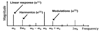
- FIG. 1 (a) and 1 (b) show the frequency characteristics according to the damage of the structure, as shown in Figure 1 (a), when there is no fatigue damage (fatigue damage) to the metal structure to the ultrasonic wave to the structure When irradiated, the frequency response is measured only at the signals of both ultrasonic frequencies.
- FIG. 1 (b) when the metal structure has fatigue damage, the damage region has a local nonlinearity, and thus, harmonics and modulation of the ultrasonic frequency component when ultrasonic waves pass through the damage region. ) Occurs.
- the present invention excites two ultrasonic waves of different frequencies to a structure, extracts a first modulation component from a signal response generated from a damaged region by a linear signal cancellation technique and a synchronous demodulation technique, and then applies the ultrasonic waves to a variable frequency of the ultrasonic waves.
- a first sideband spectrogram is generated by combining primary modulation components having different values according to the present invention, and the fatigue damage of the structure is diagnosed from the first sideband spectrogram.
- the present invention is a test result of a physical model of a fitting-lug structure connecting the fuselage and the wing of an aircraft.
- 2 (a) and 2 (b) are fitting lugs used in the experiment
- FIG. 2 (c) is a cyclic load test for fatigue damage simulation.
- a concentric double piezoelectric transducer is attached to the fitting lug.
- the low frequency pumping signal is applied to the piezoelectric transducer of the outer portion of the concentric dual piezoelectric transducer ACT
- the high frequency probe signal is the second piezoelectric transducer 4 of the inner portion of the concentric dual piezoelectric transducer ACT.
- Figure 2 (c) is a model in which the specimen is installed on the equipment that can apply a cyclic load corresponding to the actual flight time of 1000 hours
- Figure 2 (d) is a fatigue damage of about 40 mm length by the cyclic load The generated specimen is shown.
- FIG. 3 illustrates a wireless diagnostic apparatus 20 using a nonlinear ultrasonic modulation technique according to the present invention, and may diagnose fatigue cracks such as the structure shown in FIG. 2.
- the piezoelectric transducer unit 22 which vibrates the structure and senses the ultrasonic waves from the structure, and the digitizer, LRS, and SD which convert the output of the piezoelectric transducer unit 22 into digital signals, extracts a primary modulation component, and ultrasonics
- a digital signal processor for generating a first sideband spectrogram from the combination of the primary modulation components extracted by varying the frequency of the signals, diagnosing the presence of cracks from the first sideband spectrogram, and wirelessly transmitting the diagnosis result to an inspector or an inspection system. 23).
- high frequency is an ultrasonic wave of 80 kHz to 110 kHz and is called a probing signal.
- Low frequency is an ultrasonic wave of 10 kHz to 20 kHz and is called a pumping signal.
- the low frequency generator 28 generates a low frequency pumping signal according to the first control signal ctrl1.
- the pumped signal is a sine wave of 16.5 kHz, 12V.
- the high frequency generator 29 generates a probe signal having a high frequency according to the second control signal ctrl2.
- the probe signal is a 12V linear chirp signal with a frequency band of 80 kHz to 110 kHz.
- the low frequency generator 28 and the high frequency generator 29 may be implemented by a digital analog converter.
- the low frequency generator 28 and the high frequency generator 29 may further include a filter and an amplifier.
- the piezoelectric transducer unit 22 includes a first piezoelectric transducer 3 having the low frequency signal in the structure, and a second piezoelectric transducer 4 having the high frequency signal in the structure. And a third piezoelectric transducer 5 for outputting the response of the structure by the low frequency and the high frequency as an electric signal.
- the first piezoelectric transducer 3 and the second piezoelectric transducer 4 are attached to the structure to apply ultrasonic waves of different frequencies to the structure and cause vibration, and FIGS. 2 (a), 2 (b) and 2 (d). It can be implemented using the concentric double piezoelectric transducer shown in Fig. 2).
- the concentric dual piezoelectric transducer is composed of two piezoelectric transducers having the same center, one (first piezoelectric transducer 3) is a circular sensor at the center, and the other (second piezoelectric transducer 4) is a predetermined distance from the circular sensor. It is a ring-shaped sensor formed spaced apart. Referring to FIG.
- the first piezoelectric transducer 3 receives a low frequency signal through the first input terminal 31, and the second piezoelectric transducer 4 transmits a high frequency signal to the second input terminal ( 32).
- the concentric dual piezoelectric transducer is used, the same effects as those applied at the same position are obtained even when ultrasonic waves are applied at different positions.
- the third piezoelectric transducer 5 is attached to the structure 7 to convert the response generated in the structure 7 by vibration to an electrical signal.
- the digitizer 6 measures the output of the third piezoelectric transducer 5 according to the third control signal ctrl3 and converts the output of the third piezoelectric transducer 5 in the form of an analog signal into a digital signal.
- the digitizer 6 may be implemented as an analog to digital converter.
- the outputs of the high frequency generator 29 and the low frequency generator 28 are applied to the first piezoelectric transducer 3 and the second piezoelectric transducer 4, and the output of the third piezoelectric transducer 5 Is applied to the digitizer 6.
- the high frequency generator 29, the low frequency generator 28, the digitizer 6, and the piezoelectric transducers 3, 4, and 5 are connected by a cable or a transmission line.
- the digital signal processor 23 extracts a primary modulated signal by performing linear signal removal processing and synchronous demodulation processing from the response generated in the structure by the frequency signals, and generates an FSS to determine whether the structure is damaged or not, and to diagnose the diagnosis. The results are sent to a remotely located safety inspector or inspection system.
- the digital signal processor 23 includes a linear signal remover 16, a synchronization demodulator 17, an FSS generator 18, and a wireless transmitter 19.
- the linear signal cancellation technique is a unique signal processing technique that subtracts the response of the structure when the pumping signal and the probe signal are separately excited from the response of the structure when the pumping signal and the probe signal are simultaneously excited.
- the linear signal cancellation technique is described in detail below.
- the third piezoelectric transducer 5 converts the response of the structure generated by simultaneously bringing the pumping signal and the probe signal to the structure into an analog electric signal, and the digitizer 6 converts the analog electric signal into a first digital signal.
- the third piezoelectric transducer 5 and the digitizer 6 have a second digital response. Convert to a signal.
- the third piezoelectric transducer 5 and the digitizer 6 then convert the response of the generated structure with only the probe signal to the structure 7 into a third digital signal.
- the linear signal removing unit 16 removes the second digital signal and the third digital signal from the first digital signal.
- the linear signal removing unit 16 may extract only a sideband signal from the output of the digitizer.
- the linear signal remover 16 may generate a linear response u (1) from signals of the entire frequency band from the output signal u T from the structure as shown in Equation 1 below.
- the linear signal removing unit 16 may apply an equation (2) to extract the sideband signal from which an error occurring in an actual situation is removed by performing LRS.
- the signal u (3) according to Equation 1 is a theoretically possible linear signal canceled value, and the signal of Equation 2 ) Is a linear signal removal process considering the errors occurring in the actual situation.
- the synchronous demodulator 17 synchronous demodulates the output of the linear signal remover 16.
- the synchronous demodulation technique is a signal processing technique used in general communication.
- the control unit 24 varies the output frequencies of the low frequency generator 28 and the high frequency generator 29, so that both low and high frequencies are applied to the structure, only low frequencies are applied, or only high frequencies are applied.
- the signal output timing of the generator 28 and the high frequency generator 29 is controlled.
- the controller 24 selects a frequency for outputting the largest value of the first modulated signal from the first sideband spectrogram and sets the frequency of the pumping signal and the probe signal.
- the FSS generator 18 receives the output signal of the synchronous demodulator 17 according to the frequency variation of the high frequency and the low frequency according to the fourth control signal ctrl4 and extracts only the primary modulated signal to generate the FSS.
- the controller 24 varies the output frequencies of the low frequency generator 28 and the high frequency generator 29, the FSS is generated from the primary modulation components extracted from the synchronization demodulator 17 according to the changed frequency.
- Unit 18 combines to produce a first sideband spectrogram.
- the wireless transmitter 19 wirelessly transmits the output of the FSS generator 18 to an inspector or an inspection system at a remote location so that the inspector can immediately determine whether the structure is fatigue cracked.
- the wireless transmission unit 19 is a wireless communication such as code division multiple access (CDMA), zigbee, Bluetooth, Wi-Fi, wireless broadband internet, WiMAX (world interoperability for microwave access) The data is transmitted by the method.
- CDMA code division multiple access
- zigbee Bluetooth
- Wi-Fi wireless broadband internet
- WiMAX world interoperability for microwave access
- FIG. 5 illustrates output characteristics of the digitizer 6, the linear signal remover 16, and the synchronous demodulator 17 according to the LRS and SD signal processing technique and the structure damage according to the present invention.
- 5 (a) and 5 (b) are the results of analyzing the signal output from the damaged structure and the structure without damage (output of the digitizer 6) in the time-frequency band, a large difference depending on the presence of damage Therefore, it is impossible to determine the damage only by the signal output from the structure.
- 5 (c) and 5 (d) show the results of analyzing the LRS-processed signal in the time-frequency domain of the output of the digitizer 6 in the linear signal remover 16, and the linear signal remover 16
- the primary modulated signal is generated from the damaged structure (FIG. 5 (d)) and the primary modulated signal is not generated from the undamaged structure (FIG. 5 (c)).
- 5 (e) and 5 (f) are signals obtained by extracting only the primary modulated signal from the output of the digitizer 6 by applying a synchronous demodulation technique after the LRS technique to the response of the structure. Since the modulated signal is generated only when the damage occurs in the synchronous demodulator 17, the damage of the structure can be detected by the presence or absence of the modulated signal.
- the present invention fixes the frequency of the probe signal, measures the output signal of the digitizer while changing the frequency of the pumping signal, extracts only the primary modulation component by LRS and synchronous demodulation of the measured signal, and extracts the primary modulation component for each frequency. Combine to generate the FSS.
- FIG. 4 is a measurement system for performing a safety diagnosis experiment of a structure according to another embodiment of the present invention, a plurality of piezoelectric transducers (12, 13) attached to output the response of the structure than the piezoelectric transducer, It is a configuration to test the presence of error of the measurement result according to the position attached to the structure.
- the piezoelectric transducer for detecting damage to the structure is attached to two different locations. Differences in the measurement results according to the positions of the two piezoelectric transducers 12 and 13 are analyzed to be insignificant with reference to FIGS. 6 and 7. Descriptions of the configuration after the digitizer 14 (linear signal removal unit, synchronization demodulation unit, FSS generation unit, and wireless transmission unit) are the same as those shown in FIG.
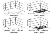
- FIG. 6 illustrates a first sideband spectrogram generated by continuously changing the frequency of the pumped signal from 10 to 20 kHz and the probe signal from 80 kHz to 110 kHz.
- 6 (a) and 6 (c) show the measurement results of the measurement system shown in FIG. 4, and the digitizer 14 from the sixth piezoelectric transducer 12 and the seventh piezoelectric transducer 13 when there is no damage to the structure.
- the frequency of the pumped signal is increased in 500 Hz from 10 kHz to 20 kHz, and the frequency of the probe signal is kept constant from 80 kHz to 110 kHz. It can be seen that the primary modulation component does not occur when there is no damage to the structure.
- 6 (b) and 6 (d) show pumping signals and probe signals from the sixth piezoelectric transducer 12 and the seventh piezoelectric transducer 13 when the structure is damaged. Is the result of generating FSS by continuously changing the frequency for each frequency.
- the primary modulation component occurs in both the sixth piezoelectric transducer 12 and the seventh piezoelectric transducer 13.
- the peculiarity is that even if the structure is damaged, there is a frequency band in which the modulation component does not occur depending on the frequency combination. Therefore, when the frequency of the pumping signal is 10 kHz to 20 kHz and the frequency of the probe signal is set to 80 kHz to 110 kHz, the output level of the primary modulated signal according to the presence or absence of damage to the structure is significantly different, 80 kHz to 110 By selecting the frequency of the probe signal in the kHz frequency band it is possible to accurately detect the presence of damage to the structure compared to the conventional safety diagnostic method.
- the frequency of the probe signal may be selected as the above frequency.
- the diagnostic apparatus using the frequency of FIG. 7 should apply a probe signal and a pumping signal of greater power to the piezoelectric transducer. 7 shows that using the frequency band shown in FIG. 6 is advantageous to low power sensor implementation.
- the controller may control the high frequency generator and the low frequency generator to output the probe signal and the pumping signal of the corresponding frequency, thereby implementing a diagnostic sensor having improved accuracy according to the temperature or the characteristics of the structure.
- the present invention can be widely used as a safety diagnostic sensor in the field of safety diagnosis management of various structures, including infrastructure, aircraft, railroad cars, and the like.
Landscapes
- Physics & Mathematics (AREA)
- General Physics & Mathematics (AREA)
- Biochemistry (AREA)
- General Health & Medical Sciences (AREA)
- Health & Medical Sciences (AREA)
- Life Sciences & Earth Sciences (AREA)
- Chemical & Material Sciences (AREA)
- Analytical Chemistry (AREA)
- Pathology (AREA)
- Immunology (AREA)
- Engineering & Computer Science (AREA)
- Acoustics & Sound (AREA)
- Signal Processing (AREA)
- Aviation & Aerospace Engineering (AREA)
- Mathematical Physics (AREA)
- Spectroscopy & Molecular Physics (AREA)
- Investigating Or Analyzing Materials By The Use Of Ultrasonic Waves (AREA)
Abstract
Description


Claims (15)
- 구조물의 안전진단 방법에 있어서,서로 다른 주파수의 신호들을 모두 인가하여 구조물을 진동시키는 단계;상기 진동에 의해 발생한 상기 구조물의 응답을 디지털 신호로 변환하는 단계;상기 디지털 신호로부터 상기 주파수 신호들의 고조파 응답과 선형 응답을 제거하고 동기복조하여 일차 변조 신호를 추출하는 단계;상기 서로 다른 주파수의 신호들 중 적어도 하나의 주파수를 변화시킴에 따라 추출된 일차 변조 신호들을 결합하여 제1 측파대 스펙트로그램(first sideband spectrogram)을 생성하는 단계 및상기 제1 측파대 스펙트로그램으로부터 상기 구조물의 균열유무를 판별하는 단계를 포함하는 것을 특징으로 하는 비선형 초음파 모듈레이션 기법을 이용한 구조물의 안전진단 방법.
- 제1항에 있어서,상기 진동에 의해 발생한 상기 구조물의 응답을 디지털 신호로 변환하는 단계 이후에,상기 주파수 신호들 중 하나를 인가하여 상기 구조물에 발생한 응답을 제2 디지털 신호로 변환하는 단계 및상기 주파수 신호들 중 다른 하나를 인가하여 상기 구조물에 발생한 응답을 제3 디지털 신호로 변환하는 단계를 더 포함하는 것을 특징으로 하는 비선형 초음파 모듈레이션 기법을 이용한 구조물의 안전진단 방법.
- 제2항에 있어서,상기 일차 변조 신호를 추출하는 단계는,상기 디지털 신호로부터 상기 제2 디지털 신호와 상기 제3 디지털 신호를 뺄셈하는 선형신호제거 단계 및상기 선형신호제거된 신호를 동기복조하여 상기 디지털 신호에서 상기 일차 변조 신호를 추출하는 단계를 포함하는 것을 특징으로 하는 비선형 초음파 모듈레이션 기법을 이용한 구조물의 안전진단 방법.
- 제1항에 있어서,상기 서로 다른 주파수의 신호들을 인가하여 구조물을 진동시키는 단계는,상기 서로 다른 주파수 신호 중 하나를 상기 구조물에 부착된 동심 이중 압전변환기의 내측에 인가하고, 다른 하나를 상기 동심 이중 압전변환기의 외측에 인가하는 것을 특징으로 비선형 초음파 모듈레이션 기법을 이용한 구조물의 안전진단 방법.
- 제1항에 있어서,상기 제1 측파대 스펙트로그램으로부터 상기 구조물의 균열유무를 판별하는 단계는,상기 구조물의 손상유무를 원격지에 있는 검사 시스템으로 무선 전송하여 실시간으로 안전진단을 수행하는 단계를 더 포함하는 것을 특징으로 하는 비선형 초음파 모듈레이션 기법을 이용한 구조물의 안전진단 방법.
- 구조물의 피로균열 계측 방법에 있어서,서로 다른 주파수의 초음파 중 하나의 초음파를 구조물에 부착된 동심 이중 압전변환기의 내측에 인가하고, 다른 하나의 초음파를 상기 동심 이중 압전변환기의 외측에 인가하여 상기 구조물을 진동시키는 단계;상기 진동에 의해 상기 구조물에 발생한 응답을 제1 디지털 신호로 변환하는 단계;상기 하나의 초음파만을 상기 동심 이중 압전변환기에 인가함으로 인해 발생한 상기 구조물의 응답을 제2 디지털 신호로 변환하는 단계;상기 다른 하나의 초음파만을 상기 동심 이중 압전변환기에 인가함으로 인해 발생한 상기 구조물의 응답을 제3 디지털 신호로 변환하는 단계 및상기 제1 디지털 신호로부터 상기 제2 디지털 신호와 상기 제3 디지털 신호를 제거한 신호를 동기복조하여 상기 구조물의 균열유무를 판별하는 단계를 포함하는 것을 특징으로 하는 비선형 초음파 모듈레이션 기법을 이용한 구조물의 피로균열 계측 방법.
- 제6항에 있어서,상기 구조물의 균열유무를 판별하는 단계는,상기 초음파들의 주파수를 연속 변화시켜가며 상기 일차 변조 신호를 추출하고, 각 주파수별 추출된 일차 변조 신호들을 결합하여 제1 측파대 스펙트로그램을 생성하고, 생성된 제1 측파대 스펙트로그램으로부터 상기 구조물의 균열유무를 판별하는 단계를 더 포함하는 것을 특징으로 하는 비선형 초음파 모듈레이션 기법을 이용한 구조물의 피로균열 계측 방법.
- 구조물의 피로균열 계측 시스템에 있어서,제1 제어 신호에 따라 저주파수의 초음파를 생성하는 저주파 생성부;제2 제어 신호에 따라 고주파수의 초음파를 생성하는 고주파 생성부;상기 구조물에 부착되어 상기 저주파수의 초음파를 상기 구조물에 인가하는 제1 압전변환기;상기 구조물에 부착되어 상기 고주파수의 초음파를 상기 구조물에 인가하는 제2 압전변환기;상기 초음파들에 의해 발생된 구조물의 응답을 전기 신호로 변환하는 제3 압전변환기;상기 제3 압전변환기의 출력을 디지털 신호로 변환하는 디지타이저;상기 제1 제어 신호와 상기 제2 제어 신호의 활성화 타이밍을 제어하는 제어부 및상기 디지타이저의 출력으로부터 선형 응답과 고조파 응답을 제거하고 동기복조하여 상기 구조물의 피로균열 정보로 출력하는 디지털 신호 처리부를 포함하는 것을 특징으로 하는 비선형 초음파 모듈레이션 기법을 이용한 구조물의 피로균열 계측 시스템.
- 제8항에 있어서,상기 제어부는,상기 저주파 생성부의 출력 주파수 또는 고주파 생성부의 출력 주파수를 가변시키거나, 상기 구조물에 저주파와 고주파가 모두 인가되거나, 저주파만 인가되거나, 고주파만 인가되도록 상기 저주파 생성부와 고주파 생성부의 신호 출력 타이밍을 제어하는 것을 특징으로 하는 비선형 초음파 모듈레이션 기법을 이용한 구조물의 피로균열 계측 시스템.
- 서로 다른 주파수의 펌핑 신호와 탐침 신호를 출력하는 주파수 생성부;상기 펌핑 신호와 상기 탐침 신호를 구조물에 인가하여 진동을 유발하고, 상기 구조물의 응답을 전기 신호로 출력하는 압전변환기부;상기 압전변환기부의 출력을 디지털 신호로 변환하는 디지타이저 및상기 디지타이저의 출력을 선형신호제거(linear response subtraction)하고 동기복조하여 제1 측파대 스펙트로그램을 생성하는 디지털 신호 처리부 및상기 제1 측파대 스펙트로그램을 원격지의 검사 시스템으로 무선 전송하는 무선 전송부를 포함하는 것을 특징으로 하는 비선형 초음파 모듈레이션 기법을 이용한 구조물의 무선 진단장치.
- 제10항에 있어서,상기 디지털 신호 처리부는,상기 펌핑 신호와 상기 탐침 신호가 모두 인가될 때의 상기 디지타이저의 출력에서 상기 펌핑 신호만 인가될 때의 상기 디지타이저의 출력과 상기 탐침 신호만 인가될 때의 상기 디지타이저의 출력을 제거하는 선형신호제거부 및상기 선형신호제거부의 출력을 동기복조하여 일차 변조 신호를 생성하는 동기복조부를 포함하는 것을 특징으로 하는 비선형 초음파 모듈레이션 기법을 이용한 구조물의 무선 진단장치.
- 제10항에 있어서,상기 디지털 신호 처리부는,상기 펌핑 신호의 주파수 또는 상기 탐침 신호의 주파수를 소정 주파수 구간에서 연속 변화시키면서 얻은 주파수별 일차 변조 신호들을 결합하여 제1 측파대 스펙트로그램을 생성하는 FSS(first sideband spectrogram) 생성부를 더 포함하는 것을 특징으로 하는 비선형 초음파 모듈레이션 기법을 이용한 구조물의 무선 진단장치.
- 제10항에 있어서,상기 제어부는,상기 제1 측파대 스펙트로그램으로부터 가장 큰 값을 갖는 일차 변조 신호에 해당하는 주파수들을 상기 펌핑 신호의 주파수와 상기 탐침 신호의 주파수로 설정하는 것을 특징으로 하는 비선형 초음파 모듈레이션 기법을 이용한 구조물의 무선 진단장치.
- 제10항에 있어서,상기 압전변환기부는,상기 구조물에 부착되어 상기 펌핑 신호를 상기 구조물에 인가하는 제1 압전변환기;상기 구조물에 부착되어 상기 탐침 신호를 상기 구조물에 인가하는 제2 압전변환기 및상기 펌핑 신호와 상기 탐침 신호에 의해 발생된 구조물의 응답을 전기 신호로 변환하는 제3 압전변환기를 포함하는 것을 특징으로 하는 비선형 초음파 모듈레이션 기법을 이용한 구조물의 무선 진단장치.
- 제10항에 있어서,상기 펌핑 신호의 주파수는 10 kHz ~ 20 kHz이고, 상기 탐침 신호의 주파수는 80 kHz ~ 110 kHz인 것을 특징으로 하는 비선형 초음파 모듈레이션 기법을 이용한 구조물의 무선 진단장치.
Priority Applications (2)
| Application Number | Priority Date | Filing Date | Title |
|---|---|---|---|
| US14/787,127 US9772315B2 (en) | 2013-04-30 | 2013-12-23 | Wireless diagnosis apparatus for structure using nonlinear ultrasonic wave modulation technique and safety diagnosis method using the same |
| CN201380076095.9A CN105164493B (zh) | 2013-04-30 | 2013-12-23 | 利用非线性超声波调制技术的构造物的无线诊断装置及利用该装置的安全诊断方法 |
Applications Claiming Priority (2)
| Application Number | Priority Date | Filing Date | Title |
|---|---|---|---|
| KR20130048072A KR101414520B1 (ko) | 2013-04-30 | 2013-04-30 | 비선형 초음파 모듈레이션 기법을 이용한 구조물의 무선 진단장치 및 그를 이용한 안전진단 방법 |
| KR10-2013-0048072 | 2013-04-30 |
Publications (1)
| Publication Number | Publication Date |
|---|---|
| WO2014178518A1 true WO2014178518A1 (ko) | 2014-11-06 |
Family
ID=51740987
Family Applications (1)
| Application Number | Title | Priority Date | Filing Date |
|---|---|---|---|
| PCT/KR2013/012037 Ceased WO2014178518A1 (ko) | 2013-04-30 | 2013-12-23 | 비선형 초음파 모듈레이션 기법을 이용한 구조물의 무선 진단장치 및 그를 이용한 안전진단 방법 |
Country Status (4)
| Country | Link |
|---|---|
| US (1) | US9772315B2 (ko) |
| KR (1) | KR101414520B1 (ko) |
| CN (1) | CN105164493B (ko) |
| WO (1) | WO2014178518A1 (ko) |
Cited By (1)
| Publication number | Priority date | Publication date | Assignee | Title |
|---|---|---|---|---|
| WO2017209329A1 (ko) * | 2016-06-03 | 2017-12-07 | 한양대학교 산학협력단 | 고전압 펄서에서 발생되는 초음파 비선형성 측정 방법 |
Families Citing this family (20)
| Publication number | Priority date | Publication date | Assignee | Title |
|---|---|---|---|---|
| KR101615563B1 (ko) * | 2015-01-07 | 2016-04-26 | 한국과학기술원 | 구조물의 피로균열 진단 방법 및 손상 진단 장치 |
| KR101699438B1 (ko) | 2015-11-12 | 2017-01-25 | 공주대학교 산학협력단 | 주파수 선택 구조를 이용한 구조물 진단 장치 및 방법 |
| KR101732494B1 (ko) * | 2016-03-29 | 2017-05-04 | 한국과학기술원 | 비선형 초음파 변조 기법을 이용한 균열 탐지 방법 |
| CN106949861B (zh) * | 2017-04-24 | 2019-01-22 | 中北大学 | 一种非线性超声在线监测金属材料应变变化的方法 |
| KR101964758B1 (ko) | 2017-06-19 | 2019-04-02 | 원광대학교 산학협력단 | 비접촉식 가진에 의한 비선형 초음파 진단 장치 |
| KR101963820B1 (ko) | 2017-06-19 | 2019-03-29 | 원광대학교 산학협력단 | 반사모드 비선형 초음파 진단 장치 |
| KR101865270B1 (ko) | 2017-07-13 | 2018-06-07 | 부경대학교 산학협력단 | 다양한 진동 스펙트럼 패턴에 대응 가능한 주파수 영역의 피로 손상도 계산방법 |
| KR102112032B1 (ko) * | 2018-07-03 | 2020-05-19 | 한국과학기술원 | 구조물의 진단 방법 및 진단 시스템 |
| KR102106940B1 (ko) | 2018-07-20 | 2020-05-06 | 원광대학교 산학협력단 | 배음 진동자를 이용한 초음파 비파괴 검사 장치 |
| KR102116051B1 (ko) | 2018-07-25 | 2020-05-27 | 원광대학교 산학협력단 | 배열형 초음파 센서를 이용한 펄스 에코형 비선형 검사 장치 |
| KR101972765B1 (ko) | 2019-01-08 | 2019-04-29 | 주식회사 다산컨설턴트 | 구조물 안전진단용 초음파 접촉매질 도포장치 |
| KR102069119B1 (ko) | 2019-09-04 | 2020-01-23 | 주식회사 수성엔지니어링 | 구조물 안전진단용 초음파 접촉매질 도포장치 |
| KR102305732B1 (ko) | 2019-12-18 | 2021-09-27 | 주식회사 포스코 | 주파수 가변형 초음파 탐상 장치 |
| KR102157303B1 (ko) | 2020-04-14 | 2020-09-17 | 주식회사 천우 | 구조물 안전진단용 초음파 접촉매질 도포장치 |
| KR102158237B1 (ko) | 2020-06-03 | 2020-09-21 | 주식회사 하나이엔씨 | 구조물 안전진단용 초음파 접촉매질 도포장치 |
| KR102387166B1 (ko) * | 2020-06-15 | 2022-04-18 | 한국과학기술원 | 교량의 변위를 추정하는 방법 및 전자 장치 |
| KR102421090B1 (ko) * | 2020-06-24 | 2022-07-15 | 한국과학기술원 | 구조물의 균열 검출 방법 및 검사 시스템 |
| EP4006517A1 (en) * | 2020-11-26 | 2022-06-01 | RO-RA Aviation Systems GmbH | Method for detecting and locating cracks in a physical structure by means of an electro-mechanical impedance technique |
| CN112946078B (zh) * | 2021-02-03 | 2022-08-05 | 山东大学 | 一种复合材料胶接质量评估和早期损伤识别方法及系统 |
| CN113237953B (zh) * | 2021-05-19 | 2022-04-29 | 西南交通大学 | 一种基于非线性超声测量疲劳微裂纹偏移角度的方法 |
Citations (5)
| Publication number | Priority date | Publication date | Assignee | Title |
|---|---|---|---|---|
| JP2001337077A (ja) * | 2000-05-30 | 2001-12-07 | Shogo Tanaka | コンクリート構造物の剥離の非破壊検査方法 |
| JP2005053613A (ja) * | 2003-08-07 | 2005-03-03 | Fukoku Co Ltd | シート状媒体搬送装置 |
| WO2009101978A1 (ja) * | 2008-02-13 | 2009-08-20 | National University Corporation Kyoto Institute Of Technology | 構造物の損傷の診断方法および装置 |
| KR20100134989A (ko) * | 2009-06-16 | 2010-12-24 | 주식회사 메카시스 | 비접촉식 구조물 고유진동 특성 측정장치. |
| KR101053422B1 (ko) * | 2008-12-22 | 2011-08-01 | 주식회사 포스코 | 비선형 초음파 발생을 이용한 강판의 내부결함 검출시스템 및 검출방법 |
Family Cites Families (10)
| Publication number | Priority date | Publication date | Assignee | Title |
|---|---|---|---|---|
| CA2169307C (en) * | 1994-12-12 | 2003-10-14 | David A. Hutchins | Non-contact characterization and inspection of materials using wideband air coupled ultrasound |
| US6850623B1 (en) * | 1999-10-29 | 2005-02-01 | American Technology Corporation | Parametric loudspeaker with improved phase characteristics |
| US6186004B1 (en) * | 1999-05-27 | 2001-02-13 | The Regents Of The University Of California | Apparatus and method for remote, noninvasive characterization of structures and fluids inside containers |
| US6486678B1 (en) * | 2000-11-28 | 2002-11-26 | Paul Spears | Method for non-destructive analysis of electrical power system equipment |
| KR100784582B1 (ko) | 2006-05-19 | 2007-12-10 | 전북대학교산학협력단 | 압전소자를 이용한 구조물의 손상계측장치 및 방법 |
| US8100015B2 (en) * | 2007-11-20 | 2012-01-24 | Kabushiki Kaisha Toshiba | Ultrasonic inspection apparatus and ultrasonic probe used for same |
| US7712369B2 (en) * | 2007-11-27 | 2010-05-11 | The Boeing Company | Array-based system and method for inspecting a workpiece with backscattered ultrasonic signals |
| CN101701880B (zh) * | 2009-08-05 | 2011-06-29 | 南京航空航天大学 | 嵌入式飞机主被动结构健康监测系统 |
| CN101806778B (zh) * | 2010-03-05 | 2011-07-27 | 北京工业大学 | 金属材料疲劳早期损伤非线性超声在线检测方法 |
| JP5442553B2 (ja) * | 2010-07-21 | 2014-03-12 | 日立建機株式会社 | 軸受の損傷検出方法 |
-
2013
- 2013-04-30 KR KR20130048072A patent/KR101414520B1/ko active Active
- 2013-12-23 WO PCT/KR2013/012037 patent/WO2014178518A1/ko not_active Ceased
- 2013-12-23 CN CN201380076095.9A patent/CN105164493B/zh active Active
- 2013-12-23 US US14/787,127 patent/US9772315B2/en not_active Expired - Fee Related
Patent Citations (5)
| Publication number | Priority date | Publication date | Assignee | Title |
|---|---|---|---|---|
| JP2001337077A (ja) * | 2000-05-30 | 2001-12-07 | Shogo Tanaka | コンクリート構造物の剥離の非破壊検査方法 |
| JP2005053613A (ja) * | 2003-08-07 | 2005-03-03 | Fukoku Co Ltd | シート状媒体搬送装置 |
| WO2009101978A1 (ja) * | 2008-02-13 | 2009-08-20 | National University Corporation Kyoto Institute Of Technology | 構造物の損傷の診断方法および装置 |
| KR101053422B1 (ko) * | 2008-12-22 | 2011-08-01 | 주식회사 포스코 | 비선형 초음파 발생을 이용한 강판의 내부결함 검출시스템 및 검출방법 |
| KR20100134989A (ko) * | 2009-06-16 | 2010-12-24 | 주식회사 메카시스 | 비접촉식 구조물 고유진동 특성 측정장치. |
Cited By (2)
| Publication number | Priority date | Publication date | Assignee | Title |
|---|---|---|---|---|
| WO2017209329A1 (ko) * | 2016-06-03 | 2017-12-07 | 한양대학교 산학협력단 | 고전압 펄서에서 발생되는 초음파 비선형성 측정 방법 |
| US10921289B2 (en) | 2016-06-03 | 2021-02-16 | Industry-University Cooperation Foundation Hanyang University | Method for measuring ultrasonic nonlinearity generated by high voltage pulser |
Also Published As
| Publication number | Publication date |
|---|---|
| US20160109416A1 (en) | 2016-04-21 |
| US9772315B2 (en) | 2017-09-26 |
| KR101414520B1 (ko) | 2014-07-04 |
| CN105164493B (zh) | 2018-02-23 |
| CN105164493A (zh) | 2015-12-16 |
Similar Documents
| Publication | Publication Date | Title |
|---|---|---|
| KR101414520B1 (ko) | 비선형 초음파 모듈레이션 기법을 이용한 구조물의 무선 진단장치 및 그를 이용한 안전진단 방법 | |
| US7447598B2 (en) | Methods and systems for automatically assessing and reporting structural health | |
| KR20120089703A (ko) | 부분적인 전기 방전들에 관련된 신호들을 검출 및 처리하기 위한 디바이스 및 방법 | |
| EP3825707B1 (en) | Generator rotor winding state detection device and method | |
| BR112017008942B1 (pt) | método e sistema para monitoramento de saúde estrutural com sincronização de frequência | |
| CN101482540A (zh) | 基于电磁层析成像技术的钢丝绳损伤检测装置及方法 | |
| SA520412459B1 (ar) | أنظمة وطرق لتوليد الموجات فوق الصوتية | |
| US9176025B2 (en) | Apparatus and method of vibration testing for manufacturing defect detection in composite insulators | |
| CN105911500A (zh) | 一种特高频局部放电在线监测系统的考核校验装置及方法 | |
| JPWO2009101978A1 (ja) | 構造物の損傷の診断方法および装置 | |
| KR101548288B1 (ko) | 반사파 계측을 이용한 배선 진단 시스템 | |
| CN115507896A (zh) | 一种涡轮发动机叶片间隙和叶尖损伤的检测方法及其装置 | |
| CN110568078B (zh) | 一种适用于岔区的钢轨断裂检测方法、装置及系统 | |
| CN110286083B (zh) | 外腐蚀综合检测方法 | |
| EP3078967A1 (en) | A system and a method for detecting damage | |
| Liu et al. | Investigation of textured sensing skin for monitoring fatigue cracks on fillet welds | |
| CN120314449A (zh) | 电池包检测方法、装置、系统、设备、介质和产品 | |
| CN207232373U (zh) | 一种基于纵波法的局部放电超声检测传感器校准系统 | |
| CN207232374U (zh) | 一种基于横波法的局部放电超声检测传感器校准系统 | |
| JPH0875706A (ja) | 機体検査装置 | |
| CN116577406A (zh) | 一种实时高精度acfm裂纹状态监测方法 | |
| WO2016017991A1 (ko) | 전자기 유도 센서를 활용한 비파괴 피로 검사 장치 및 그 검사 방법 | |
| Cao et al. | Research on eddy current testing technology for lead seal crack defects of high voltage cable | |
| CN208239221U (zh) | 抗扭试验中绝缘子疲劳损伤程度检测装置及系统 | |
| EP2235682B1 (en) | Methods and systems for automatically assessing and reporting structural health |
Legal Events
| Date | Code | Title | Description |
|---|---|---|---|
| WWE | Wipo information: entry into national phase |
Ref document number: 201380076095.9 Country of ref document: CN |
|
| 121 | Ep: the epo has been informed by wipo that ep was designated in this application |
Ref document number: 13883615 Country of ref document: EP Kind code of ref document: A1 |
|
| WWE | Wipo information: entry into national phase |
Ref document number: 14787127 Country of ref document: US |
|
| NENP | Non-entry into the national phase |
Ref country code: DE |
|
| 122 | Ep: pct application non-entry in european phase |
Ref document number: 13883615 Country of ref document: EP Kind code of ref document: A1 |