WO2014178338A1 - Tire manufacturing method and tire - Google Patents
Tire manufacturing method and tire Download PDFInfo
- Publication number
- WO2014178338A1 WO2014178338A1 PCT/JP2014/061666 JP2014061666W WO2014178338A1 WO 2014178338 A1 WO2014178338 A1 WO 2014178338A1 JP 2014061666 W JP2014061666 W JP 2014061666W WO 2014178338 A1 WO2014178338 A1 WO 2014178338A1
- Authority
- WO
- WIPO (PCT)
- Prior art keywords
- rubber
- tire
- base
- mod
- top rubber
- Prior art date
Links
Images

Classifications
-
- B—PERFORMING OPERATIONS; TRANSPORTING
- B29—WORKING OF PLASTICS; WORKING OF SUBSTANCES IN A PLASTIC STATE IN GENERAL
- B29D—PRODUCING PARTICULAR ARTICLES FROM PLASTICS OR FROM SUBSTANCES IN A PLASTIC STATE
- B29D30/00—Producing pneumatic or solid tyres or parts thereof
- B29D30/0005—Pretreatment of tyres or parts thereof, e.g. preheating, irradiation, precuring
-
- B—PERFORMING OPERATIONS; TRANSPORTING
- B29—WORKING OF PLASTICS; WORKING OF SUBSTANCES IN A PLASTIC STATE IN GENERAL
- B29D—PRODUCING PARTICULAR ARTICLES FROM PLASTICS OR FROM SUBSTANCES IN A PLASTIC STATE
- B29D30/00—Producing pneumatic or solid tyres or parts thereof
- B29D30/06—Pneumatic tyres or parts thereof (e.g. produced by casting, moulding, compression moulding, injection moulding, centrifugal casting)
- B29D30/52—Unvulcanised treads, e.g. on used tyres; Retreading
- B29D30/66—Moulding treads on to tyre casings, e.g. non-skid treads with spikes
-
- Y—GENERAL TAGGING OF NEW TECHNOLOGICAL DEVELOPMENTS; GENERAL TAGGING OF CROSS-SECTIONAL TECHNOLOGIES SPANNING OVER SEVERAL SECTIONS OF THE IPC; TECHNICAL SUBJECTS COVERED BY FORMER USPC CROSS-REFERENCE ART COLLECTIONS [XRACs] AND DIGESTS
- Y02—TECHNOLOGIES OR APPLICATIONS FOR MITIGATION OR ADAPTATION AGAINST CLIMATE CHANGE
- Y02T—CLIMATE CHANGE MITIGATION TECHNOLOGIES RELATED TO TRANSPORTATION
- Y02T10/00—Road transport of goods or passengers
- Y02T10/80—Technologies aiming to reduce greenhouse gasses emissions common to all road transportation technologies
- Y02T10/86—Optimisation of rolling resistance, e.g. weight reduction
Definitions
- the present invention relates to a tire manufacturing method and a tire, and more particularly, to a tire manufacturing method and a tire for manufacturing a tire by integrating an individually vulcanized base tire and a top rubber.
- the top rubber and the base tire are individually vulcanized and molded, and an adhesive rubber layer is formed on the outer periphery of the base rubber of the base tire.
- a tire manufacturing method is known in which a top rubber is bonded onto an adhesive rubber layer, and the tire is manufactured by integrating the top rubber and a base tire by vulcanizing the adhesive rubber layer.
- the top rubber used in such a tire manufacturing method is easy to tear when the thickness at the groove bottom is thin in handling such as when it is attached to a base tire, and causes a defect, so that it has an appropriate thickness that can prevent tearing.
- the total thickness of the tread portion obtained by adding the thickness of the base rubber to the thickness of the top rubber is the conventional tire manufacturing method. Therefore, there is a problem in that a large running strain is generated in the tread portion, the heat generation amount is increased, the rolling resistance performance is deteriorated, and uneven wear is caused.
- the thickness at the tread portion is optimized and the heat generation amount is suppressed to improve the rolling resistance performance. It is an object of the present invention to provide a tire manufacturing method and a tire that can be used.
- a tire manufacturing method includes a step of vulcanizing and molding a top rubber to be a contact portion with a road surface, and a base tire having a base rubber to which the top rubber is attached on an outer peripheral portion. And a step of molding the tire by integrating the top rubber and the base tire.
- the loss tangent tan ⁇ of the base rubber is smaller than the loss tangent tan ⁇ of the top rubber.
- the 100% Mod of the base rubber ranges from 60% to 85% of the 100% Mod of the top rubber.
- the thickness of the base rubber is in the range of 10% to 30% of the total thickness of the tread portion in the tire.
- FIG. 1 is a cross-sectional view showing an embodiment of a tire in which a vulcanized base tire and a tread suitable for the tire manufacturing method according to the present invention are integrated.
- the tire 1 includes a base tire 2, a cushion rubber 3, and a top rubber 4.
- the base tire 2 includes a bead filler 11 mainly composed of a bead core 11, a carcass 12, a belt layer 13 mainly composed of a cord member, and a plurality of types of rubber members fleshing a skeleton composed of the cord member, an inner liner 16, Side rubber 17 and base rubber 18 are provided.
- the bead core 11 is a member formed in a ring shape by bundling steel cords called bead cords, and is provided on the left and right inner diameter portions of the base tire.
- the carcass 12 is wound around a pair of bead cores 11, and a reinforcing cord is oriented in the radial direction (radial direction) of the base tire to form a toroidal shape.
- the belt layer 13 is formed by laminating a plurality of belts. Each belt constituting the belt layer 13 is formed by laminating so that the reinforcing cords of adjacent belts are aligned so that the extending direction of the reinforcing cords is inclined with respect to the circumferential direction of the base tire Is done.
- the bead filler 15 is provided adjacent to the outside in the radial direction of the bead core 11 so as to reinforce the bead portion in the base tire 2, and is wound up together with the bead core 11 by the end portion side of the carcass 12.
- the inner liner 16 is provided so as to cover the entire inner peripheral surface of the carcass 12.
- a belt undercushion rubber 19 is provided between the lower surface on the end side of the belt layer 13 and the carcass 12, and serves as a cushion at the end of the belt layer 13 to peel the belt layer 13 from the rubber member. Is suppressed.
- the side rubber 17 is provided so as to cover the outer side surface of the carcass 12 and forms a side surface portion of the base tire 2.
- the base rubber 18 is provided so as to cover the outer periphery of the belt layer 13 and the upper end side of the side rubber 17, and forms the outer peripheral portion of the base tire 2.
- a top rubber attaching surface 2a for attaching the top rubber 4 is molded into a predetermined shape on the outer peripheral portion.
- the top rubber sticking surface 2a is formed in a smooth flat surface shape in a cross-sectional view.
- flat surface shape shows the shape formed in the top rubber sticking surface 2a at the both ends of the width direction at linear form, or the circular-arc-shaped curve with a large curvature radius convex toward the radial direction outer side or inner side.
- the top rubber attaching surface 2a is formed in an arc shape.
- the arc-shaped curve is such that the center of curvature is set in the tire center direction, one radius of curvature from the tire equator O toward the end in the width direction, or a gradual radius of curvature from the tire equator O toward the end. Is formed to be small.
- the loss tangent tan ⁇ is a value measured under the conditions of a temperature of 25 ° C., a strain of 2%, and a frequency of 52 Hz, and is a value indicating how much energy is absorbed (changes to heat) when the material is deformed. is there.
- 100% Mod is a tensile test performed on a rubber test piece prepared in accordance with JISK6251.
- the loss tangent tan ⁇ of the top rubber 4 and the base rubber 18 is calculated using the storage elastic modulus E ′.
- the storage elastic modulus E ′ and the loss tangent tan ⁇ of the top rubber 4 and the base rubber 18 are Based on values measured at 25 ° C. at a frequency of 52 Hz, an initial distortion rate of 2%, and a dynamic distortion rate of 2%.
- the 100% Mod of the base rubber 18 is less than 1.6 MPa, the hardness of the base rubber 18 becomes too soft, and rolling occurs with the top rubber 4 attached to the base rubber 18.
- the tread portion formed by the top rubber 4 generates heat and deteriorates rolling resistance performance.
- a rubber whose 100% Mod is 1.6 MPa or more for the base rubber 18 it is possible to prevent rolling of the tread portion and improve rolling resistance performance.
- the base rubber 18 is made of rubber having 100% Mod in the range of 75% to 80% of 100% Mod of the top rubber 4 so that the running strain is balanced between the top rubber 4 and the base rubber 18. Since it is well absorbed, heat generation in the tread portion is suppressed, and rolling resistance performance can be improved.
- the thickness H2 of the base rubber 18 is set in the range of 10% to 30% of the total tread thickness H1.
- the thickness H2 of the base rubber 18 is defined by the distance to the base tire surface 1a that is the outer peripheral surface of the base rubber 18 in the normal direction of the curve along the outer peripheral surface 13a of the belt layer 13. Further, the total thickness H1 of the tread portion is defined by the distance to the surface 4a of the top rubber 4 in the normal direction of the curve along the outer peripheral surface of the belt layer 13.
- the thickness H2 of the base rubber 18 By setting the thickness H2 of the base rubber 18 within the above range, it is possible to absorb the running strain when using the tire in a well-balanced manner. For example, when the thickness H2 of the base rubber 18 exceeds 30% of the total tread thickness H1, the volume of the tread, which is a heat generation factor, increases, so that the rolling resistance increases and the rolling resistance performance decreases. In addition, since the proportion of the base rubber 18 that is softer than the top rubber 4 is increased in the tread portion, the tread portion rolls due to friction during traveling, which affects the steering stability performance and the like.
- the running strain cannot be absorbed in a balanced manner in the tread portion, and the running strain is absorbed only by the top rubber 4, and therefore the top rubber 2 generates abnormal heat. Rolling resistance performance is reduced.
- an unvulcanized adhesive rubber 3 called a cushion rubber for attaching the top rubber 4 is provided on the top rubber attaching surface 2 a formed by the outer peripheral surface of the base rubber 18.
- the adhesive rubber 3 is formed into a sheet having a predetermined thickness or is liquefied, and is formed uniformly on the top rubber attaching surface 1a with a predetermined thickness H3.
- the adhesive rubber 3 may be formed with a thickness H3 of 1 mm or less, and more preferably, the adhesive rubber 3 is formed as thin and uniform as possible to improve rolling resistance performance.
- the top rubber 4 stuck on the top rubber sticking surface 2a of the base tire 2 through the adhesive rubber 3 is vulcanized and molded into a belt-like shape or an annular shape having a predetermined length.
- a tread pattern is molded on the other surface, and a pasting surface 4b having a predetermined shape corresponding to the shape of the top rubber pasting surface 2a is formed on the other surface.
- the top rubber 4 is molded such that the groove bottom thickness H5 from the groove bottom 4A of the tread pattern to the sticking surface 4b is 2 mm or more. Thereby, the tearing which arises in a groove bottom part at the time of handling of the top rubber 2 can be prevented.
- the groove bottom thickness H5 is molded in the range of 2 mm to 4 mm.
- the groove bottom portion thickness H5 is excessively thicker than necessary, the volume of rubber forming the sticking surface 4b of the top rubber 4 becomes too large, heat dissipation deteriorates, and rolling resistance increases (decreases rolling resistance performance). Therefore, it should be set within a range of at least 2 mm, preferably 2 mm or more and 4 mm or less.
- the tire 1 is manufactured through a top rubber molding step, a base tire molding step, an adhesive rubber layer forming step, a top rubber sticking step, and a vulcanization step.
- Top rubber molding process for example, a mold having a molding surface for molding a tread pattern on an unvulcanized top rubber member molded into a strip shape with a predetermined thickness and a predetermined length, and a bonding surface 4b
- the top rubber 4 is vulcanized and molded by sandwiching it with a mold having a molding surface for molding and vulcanizing at a predetermined temperature.
- the top rubber 4 is molded such that the thickness H5 from the groove bottom 4A of the tread pattern to the sticking surface 4b is 2 mm or more, or 2 mm or more and 4 mm or less.
- Base tire molding step In the base tire molding step, first, an unvulcanized sheet-like inner liner rubber member that becomes the inner liner 16 is wound around the circumferential direction in a cylindrical molding drum, and the inner liner rubber member An unvulcanized sheet-like carcass member that becomes the carcass 12 is wound around the outer periphery of the carcass 12.
- a member in which the bead core 11 and the bead filler 15 are integrated is fitted from both ends of the molding drum to both ends on the outer periphery of the carcass member, and the bead core member and the bead filler rubber member are connected to the end of the carcass member.
- the sides are folded and rolled up to form a bead area.
- the bulging means built in the molding drum is operated to bulge the center in the width direction of the laminated member group so as to form a toroidal shape.
- the under cushion rubber member is wound, and the rotation center side rubber member is wound around both regions corresponding to positions corresponding to the side regions of the base tire 2 from the left and right bead regions.
- the belt layer 13 is formed by winding a plurality of unvulcanized belts formed in a band shape on the outer periphery of the center of the most bulged carcass member so as to be laminated.
- the side rubber members are wound around the outside of the belt layer 13.
- a green rubber tire is formed by winding and laminating a base rubber member serving as the base rubber 18 on the outer periphery of the belt layer 13 and the ends of the left and right side rubber members.
- the green tire is put into a mold and vulcanized to form a tire 2.
- This mold includes a molding surface that molds the base rubber 18 that forms the outer peripheral portion of the base tire 2 into a straight line or an arcuate curve that protrudes radially outward or inward.
- Adhesive rubber layer forming process A sheet having a predetermined thickness, for example, a thickness H3 of 1 mm, is formed on the top rubber affixing surface 2a which is the outer periphery of the base rubber 18 of the base tire 2 vulcanized and molded in the base tire molding process.
- the bonding rubber 3 is disposed by winding the molded unvulcanized cushion rubber for one turn of the tire.
- Top rubber pasting process The top rubber 4 vulcanized and molded in the top rubber molding process is wound around the top rubber 2 on the top rubber pasting surface 2a of the base tire 2 on which the adhesive rubber 3 is disposed, and the top rubber is wound around the base tire 2 4 is affixed.
- ⁇ Vulcanization process After covering the outer surface of the base tire 2 with the top rubber 4 applied in the top rubber application process with a foreskin body, it is put into a vulcanizer called a vulcanizing can, and the foreskin body and the base tire
- the tire 1 is manufactured by integrating the base tire 2 and the top rubber 4 by heating the bonding rubber 3 at a predetermined temperature while adjusting the air pressure between the outer surface and the outer surface.
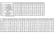
- FIG. 2 shows a comparison between a tire manufactured by a manufacturing method according to the present invention (Examples 1 to 13), a tire manufactured by a conventional tire manufacturing method (conventional example), and a tire manufacturing method according to the present invention. It is the table
- A is manufactured by a conventional tire manufacturing method in which an unvulcanized top rubber is provided on a base rubber of an unvulcanized base tire and integrally molded by a mold.
- B is a tire in which the top rubber 4 and the base tire 2 are integrally vulcanized and molded, and then the top rubber 4 and the base tire 2 are integrated.
- (2) is the elastic modulus of the base rubber 18 and indicates the ratio (%) of 100% Mod to 100% Mod of the top rubber 4.
- (3) is the thickness H2 of the base rubber 18, and the ratio to the total tread rubber thickness H1 is expressed as a percentage (%).
- the partial wear in (5) indicates whether or not partial wear actually occurred after traveling 30000 km.
- Rolling resistance performance and (7) steering stability are shown by relative evaluation based on a conventional example as a standard (100). The higher the numerical value, the better the performance.
- Comparative Example 1 to Comparative Example 7 and Example 1 to Example 13 show no uneven wear due to the difference in tire formation from the conventional example.
- the top rubber 4 and the base tire 2 are individually vulcanized and molded, so that the top rubber 4 and the base tire 2 are integrated, so that the boundary surface between the top rubber 4 and the base rubber 18 in the tread portion is undulated. Since it does not occur, it was confirmed that a tire without uneven wear can be manufactured. Further, in the tire of Example 3 in which only the tire forming method is changed with the same specifications as the conventional example, the rolling resistance performance is improved as compared with the conventional manufacturing method.
- Comparative Example 1 since 100% Mod of the base rubber 18 is 90% with respect to 100% Mod of the top rubber 4, the hardness of the base rubber 18 in the tread portion is hard, and only the top rubber 4 is deformed. This is considered to have reduced the rolling resistance performance. This is because, as shown in Comparative Example 7, when the 100% Mod of the base rubber 18 is hardened, the same result as in Comparative Example 1 is obtained, so that the base rubber 18 is too hard. it is obvious. In Comparative Example 2, since 100% Mod of the base rubber 18 is 55% of 100% Mod of the top rubber 4, the hardness of the base rubber 18 in the tread portion becomes too soft, and only the top rubber 4 is deformed. Therefore, it is considered that the rolling resistance performance was lowered.
- a tire excellent in rolling resistance performance can be obtained by using a rubber material having elasticity in the range of 60% to 85% of 100% Mod of the base rubber 18 for the top rubber 4.
- the elasticity of the base rubber 18 relative to the elasticity of the top rubber 4 is set in the range of 75% to 80% as shown in the second and third embodiments, so that the running strain is balanced and heat generation is reduced.
- a tire having more excellent rolling resistance performance can be obtained.
- Comparative Examples 3, 4, Example 3, Example 6, and Example 7 the ratio of the elasticity of the base rubber 18 to the elasticity of the top rubber 4 and the 100% Mod of the base rubber 18 are the same.
- Example 3, Example 6 and Example 7 the rolling resistance performance is improved compared to the conventional example, but in Comparative Examples 3 and 4, the rolling resistance performance is lowered.
- the steering stability performance has also declined.
- Comparative Example 3 since the thickness of the base rubber 18 was set to 35% of the total tread thickness H1, the volume of the tread portion, which is a heat generation factor, increased, and accordingly, the rolling resistance increased and the rolling resistance performance.
- the tread portion rolls due to friction during running and affects the steering stability performance. It is thought that it was lowered.
- Comparative Example 4 since the thickness H2 of the base rubber 18 is 5% of the total thickness H1 of the tread portion, the running strain cannot be absorbed in a balanced manner in the tread portion, and the running strain is absorbed only by the top rubber 4. Therefore, it is considered that the top rubber 2 abnormally generated heat and lowered the rolling resistance performance. In this case, the evaluation of the steering stability performance did not decrease because the rigidity in the tread portion was obtained. Therefore, it can be seen that the thickness of the base rubber 18 may be set in the range of 10% to 30% of the total tread thickness H1 as shown in Examples 3, 6 and 7.
- Comparative Example 5 Example 3, Example 11 to Example 13.
- Comparative Example 5 Example 3, and Examples 11 to 13 when the 100% Mod is in the range of 1.5 MPa to 1.9 MPa, the rolling resistance performance is improved as compared with the conventional example.
- Comparative Example 5 the steering stability performance is lowered as compared with Example 3, Example 11 to Example 13 and the conventional example. It is considered that this is because the base rubber 18 in the tread portion is too soft, so that the entire tread portion rolls and the steering stability performance is lowered.
- the thickness H2 of the base rubber 18 may be set to be 10% or more and 30% or less of the total tread thickness H1, and the hardness of the base rubber 18 may be set.
- the rubber within the range of 60% to 85% of the hardness of the top rubber 4, it is possible to improve the rolling resistance performance and to manufacture the tire 1 free from uneven wear.
- a rubber whose 100% Mod is 1.6 MPa or more for the base rubber 18 a tire having more excellent rolling resistance performance can be manufactured.
- the sticking surface 4b of the top rubber 4 has been described as a convex shape toward the radially outer side.
- the present invention is not limited thereto, and the convex surface is a straight line toward the both ends in the width direction or radially inward toward the tire center direction. It may be formed by the arc-shaped curve.
Abstract
The purpose of the present invention is to provide: a tire manufacturing method, which is capable of improving rolling resistance performance by optimizing the thickness of the tire in the tread section and limiting the amount of heat generated in the tread section during travel; and a tire. A tire manufacturing method having: a process for vulcanizing/molding a top rubber, which becomes the section that contacts the road surface; a process for vulcanizing/molding a base tire, the outer circumference of which is provided with a base rubber on which the top rubber is glued; and a process for forming the tire by unifying the top rubber and the base tire. The loss tangent tan δ of the base rubber is smaller than the loss tangent tan δ of the top rubber. Moreover, the 100% Mod for the base rubber is in the range of 60% to 85% of the 100% Mod of the top rubber and the thickness of the base rubber is in the range of 10% to 30% of the total thickness of the tread section in the tire.
Description
本発明は、タイヤ製造方法及びタイヤに関し、特に、個別に加硫成型された台タイヤとトップゴムとを一体にしてタイヤを製造するタイヤ製造方法及びタイヤに関する。
The present invention relates to a tire manufacturing method and a tire, and more particularly, to a tire manufacturing method and a tire for manufacturing a tire by integrating an individually vulcanized base tire and a top rubber.
従来、未加硫の台タイヤの外周部を形成するベースゴムに、タイヤにおける踏面となる未加硫のトップゴムを設けてモールドにより一体に加硫成型するタイヤ製造方法が知られている。この未加硫のベースゴムとトップゴムは、タイヤのトレッド部を構成するが、モールドによる加硫成型時に、トップゴムとベースゴムとの境界面に流れが生じて境界面にうねりとなる。このうねりは、トレッド部における剛性差を生じさせる要因となりタイヤに偏摩耗を生じさせてしまう。そこで、このうねりを防止するため、例えば特許文献1のように、トップゴムと台タイヤとを個別に加硫成型し、台タイヤのベースゴムの外周上に接着ゴム層を形成したのちに、この接着ゴム層上にトップゴムを貼り付け、接着ゴム層を加硫することでトップゴムと台タイヤとを一体にしてタイヤを製造するタイヤ製造方法が知られている。このようなタイヤ製造方法に用いられるトップゴムは、台タイヤに貼り付けるときなどの取扱いにおいて溝底における厚さが薄いとちぎれ易く、不良発生の要因となるため、ちぎれを防止できる適度な厚さに設定されている。
しかしながら、上記のように、トップゴムの取扱いを考えて溝底の厚さを設定した場合、トップゴムの厚さにベースゴムの厚さを加えたトレッド部総厚さが、従来のタイヤ製造方法で製造されたトレッド部における厚さよりも厚くなるため、トレッド部に大きな走行ひずみが発生して発熱量が大きくなり、転がり抵抗性能を低下させ、偏摩耗を生じさせてしまう問題があった。 2. Description of the Related Art Conventionally, there is known a tire manufacturing method in which an unvulcanized top rubber serving as a tread surface of a tire is provided on a base rubber that forms an outer peripheral portion of an unvulcanized stand tire and integrally vulcanized and molded by a mold. The unvulcanized base rubber and the top rubber constitute a tread portion of the tire. At the time of vulcanization molding by a mold, a flow is generated at the boundary surface between the top rubber and the base rubber, and the boundary surface is swelled. This waviness causes a difference in rigidity in the tread portion, and causes uneven wear on the tire. Therefore, in order to prevent this undulation, for example, as disclosed inPatent Document 1, the top rubber and the base tire are individually vulcanized and molded, and an adhesive rubber layer is formed on the outer periphery of the base rubber of the base tire. A tire manufacturing method is known in which a top rubber is bonded onto an adhesive rubber layer, and the tire is manufactured by integrating the top rubber and a base tire by vulcanizing the adhesive rubber layer. The top rubber used in such a tire manufacturing method is easy to tear when the thickness at the groove bottom is thin in handling such as when it is attached to a base tire, and causes a defect, so that it has an appropriate thickness that can prevent tearing. Is set to
However, as described above, when the thickness of the groove bottom is set in consideration of handling of the top rubber, the total thickness of the tread portion obtained by adding the thickness of the base rubber to the thickness of the top rubber is the conventional tire manufacturing method. Therefore, there is a problem in that a large running strain is generated in the tread portion, the heat generation amount is increased, the rolling resistance performance is deteriorated, and uneven wear is caused.
しかしながら、上記のように、トップゴムの取扱いを考えて溝底の厚さを設定した場合、トップゴムの厚さにベースゴムの厚さを加えたトレッド部総厚さが、従来のタイヤ製造方法で製造されたトレッド部における厚さよりも厚くなるため、トレッド部に大きな走行ひずみが発生して発熱量が大きくなり、転がり抵抗性能を低下させ、偏摩耗を生じさせてしまう問題があった。 2. Description of the Related Art Conventionally, there is known a tire manufacturing method in which an unvulcanized top rubber serving as a tread surface of a tire is provided on a base rubber that forms an outer peripheral portion of an unvulcanized stand tire and integrally vulcanized and molded by a mold. The unvulcanized base rubber and the top rubber constitute a tread portion of the tire. At the time of vulcanization molding by a mold, a flow is generated at the boundary surface between the top rubber and the base rubber, and the boundary surface is swelled. This waviness causes a difference in rigidity in the tread portion, and causes uneven wear on the tire. Therefore, in order to prevent this undulation, for example, as disclosed in
However, as described above, when the thickness of the groove bottom is set in consideration of handling of the top rubber, the total thickness of the tread portion obtained by adding the thickness of the base rubber to the thickness of the top rubber is the conventional tire manufacturing method. Therefore, there is a problem in that a large running strain is generated in the tread portion, the heat generation amount is increased, the rolling resistance performance is deteriorated, and uneven wear is caused.
そこで本発明では、個別に加硫成型されたトップゴムと台タイヤとを一体にしてなるタイヤ製造方法において、トレッド部における厚さを最適にして、発熱量を抑制することで転がり抵抗性能を向上させることができるタイヤ製造方法及びタイヤを提供することを目的とする。
Therefore, in the present invention, in the tire manufacturing method in which the individually vulcanized and molded top rubber and the base tire are integrated, the thickness at the tread portion is optimized and the heat generation amount is suppressed to improve the rolling resistance performance. It is an object of the present invention to provide a tire manufacturing method and a tire that can be used.
上記課題を解決するための本発明に係るタイヤ製造方法は、路面との接地部となるトップゴムを加硫成型する工程と、トップゴムが貼付されるベースゴムを外周部に備える台タイヤを加硫成型する工程と、トップゴム及び台タイヤを一体にしてタイヤを成形する工程とを有する。前記ベースゴムの損失正接tanδはトップゴムの損失正接tanδより小さい。前記ベースゴムの100%Modはトップゴムの100%Modの60%から85%の範囲である。前記ベースゴムの厚さは、タイヤにおけるトレッド部総厚さの10%から30%の範囲である。上述の構成によって、タイヤの発熱量を低減させることで、転がり抵抗性能を向上させ、偏摩耗が生じないタイヤを製造することができる。
In order to solve the above problems, a tire manufacturing method according to the present invention includes a step of vulcanizing and molding a top rubber to be a contact portion with a road surface, and a base tire having a base rubber to which the top rubber is attached on an outer peripheral portion. And a step of molding the tire by integrating the top rubber and the base tire. The loss tangent tan δ of the base rubber is smaller than the loss tangent tan δ of the top rubber. The 100% Mod of the base rubber ranges from 60% to 85% of the 100% Mod of the top rubber. The thickness of the base rubber is in the range of 10% to 30% of the total thickness of the tread portion in the tire. With the above configuration, by reducing the amount of heat generated by the tire, it is possible to manufacture a tire that improves rolling resistance performance and does not cause uneven wear.
図1は、本発明に係るタイヤ製造方法に好適な加硫成型済みの台タイヤとトレッドとが一体にされたタイヤの一実施形態を示す断面図である。図1に示すように、タイヤ1は、台タイヤ2と、クッションゴム3と、トップゴム4とにより構成される。
FIG. 1 is a cross-sectional view showing an embodiment of a tire in which a vulcanized base tire and a tread suitable for the tire manufacturing method according to the present invention are integrated. As shown in FIG. 1, the tire 1 includes a base tire 2, a cushion rubber 3, and a top rubber 4.
台タイヤ2は、コード部材を主体として構成されるビードコア11、カーカス12、ベルト層13と、コード部材等からなる骨格を肉付けする複数種類のゴム部材を主体とするビードフィラー15、インナーライナー16、サイドゴム17、ベースゴム18を備える。
ビードコア11は、ビードコードと呼ばれるスチールコードを束ねてリング状に形成された部材であって、台タイヤの左右内径部にそれぞれ設けられている。カーカス12は、一対のビードコア11に巻きつけられ、補強コードが台タイヤの半径方向(ラジアル方向)に配向されてトロイダル状をなしている。ベルト層13は、複数のベルトを積層して形成される。ベルト層13を構成する各ベルトは、補強コードの延長方向が台タイヤの円周方向に対して傾斜するように配向され、隣接して重なるベルトの補強コードが互いに交錯するように積層して形成される。 Thebase tire 2 includes a bead filler 11 mainly composed of a bead core 11, a carcass 12, a belt layer 13 mainly composed of a cord member, and a plurality of types of rubber members fleshing a skeleton composed of the cord member, an inner liner 16, Side rubber 17 and base rubber 18 are provided.
Thebead core 11 is a member formed in a ring shape by bundling steel cords called bead cords, and is provided on the left and right inner diameter portions of the base tire. The carcass 12 is wound around a pair of bead cores 11, and a reinforcing cord is oriented in the radial direction (radial direction) of the base tire to form a toroidal shape. The belt layer 13 is formed by laminating a plurality of belts. Each belt constituting the belt layer 13 is formed by laminating so that the reinforcing cords of adjacent belts are aligned so that the extending direction of the reinforcing cords is inclined with respect to the circumferential direction of the base tire Is done.
ビードコア11は、ビードコードと呼ばれるスチールコードを束ねてリング状に形成された部材であって、台タイヤの左右内径部にそれぞれ設けられている。カーカス12は、一対のビードコア11に巻きつけられ、補強コードが台タイヤの半径方向(ラジアル方向)に配向されてトロイダル状をなしている。ベルト層13は、複数のベルトを積層して形成される。ベルト層13を構成する各ベルトは、補強コードの延長方向が台タイヤの円周方向に対して傾斜するように配向され、隣接して重なるベルトの補強コードが互いに交錯するように積層して形成される。 The
The
ビードフィラー15は、台タイヤ2におけるビード部を補強するようにビードコア11の半径方向外側に隣接して設けられ、カーカス12の端部側によってビードコア11とともに巻き上げられている。インナーライナー16は、カーカス12の内周面全域を被覆するように設けられている。なお、ベルト層13の端部側の下面とカーカス12との間には、ベルトアンダークッションゴム19が設けられており、ベルト層13の端部におけるクッションとなってゴム部材に対するベルト層13の剥離を抑制している。
サイドゴム17は、カーカス12の外側側面を覆うように設けられ、台タイヤ2における側面部を形成する。 Thebead filler 15 is provided adjacent to the outside in the radial direction of the bead core 11 so as to reinforce the bead portion in the base tire 2, and is wound up together with the bead core 11 by the end portion side of the carcass 12. The inner liner 16 is provided so as to cover the entire inner peripheral surface of the carcass 12. A belt undercushion rubber 19 is provided between the lower surface on the end side of the belt layer 13 and the carcass 12, and serves as a cushion at the end of the belt layer 13 to peel the belt layer 13 from the rubber member. Is suppressed.
Theside rubber 17 is provided so as to cover the outer side surface of the carcass 12 and forms a side surface portion of the base tire 2.
サイドゴム17は、カーカス12の外側側面を覆うように設けられ、台タイヤ2における側面部を形成する。 The
The
ベースゴム18は、ベルト層13の外周及びサイドゴム17の上端側を覆うように設けられ、台タイヤ2における外周部を形成する。この外周部には、トップゴム4を貼付するためのトップゴム貼付面2aが所定形状に成型される。トップゴム貼付面2aは、図1に示すように、断面視において、滑らかな平坦面状に形成される。なお、平坦面状とは、トップゴム貼付面2aにおいて、幅方向両端にかけて直線状、あるいは径方向外側又は内側に向かって凸状の曲率半径の大きな円弧状曲線で形成された形状を示す。本実施形態では、同図に示すように、トップゴム貼付面2aが円弧状に形成されるものとする。この場合の円弧状曲線は、曲率中心がタイヤ中心方向に設定され、タイヤ赤道部Oから幅方向端部に向けて1つの曲率半径、又は、タイヤ赤道部Oから端部に向けて漸次曲率半径が小さくなるように形成される。
The base rubber 18 is provided so as to cover the outer periphery of the belt layer 13 and the upper end side of the side rubber 17, and forms the outer peripheral portion of the base tire 2. A top rubber attaching surface 2a for attaching the top rubber 4 is molded into a predetermined shape on the outer peripheral portion. As shown in FIG. 1, the top rubber sticking surface 2a is formed in a smooth flat surface shape in a cross-sectional view. In addition, flat surface shape shows the shape formed in the top rubber sticking surface 2a at the both ends of the width direction at linear form, or the circular-arc-shaped curve with a large curvature radius convex toward the radial direction outer side or inner side. In this embodiment, as shown in the figure, the top rubber attaching surface 2a is formed in an arc shape. In this case, the arc-shaped curve is such that the center of curvature is set in the tire center direction, one radius of curvature from the tire equator O toward the end in the width direction, or a gradual radius of curvature from the tire equator O toward the end. Is formed to be small.
上記ベースゴム18には、損失正接tanδが後述するトップゴム4の損失正接tanδより小さく、かつ、100%Modがトップゴム4の100%Modの60%から85%の範囲のゴムが用いられる。ここで、損失正接tanδは、温度25℃、歪2%、及び周波数52Hzの条件で測定した値で、材料が変形する際に、どのくらいエネルギーを吸収するか(熱に変わるか)を示す値である。また、100%Modとは、JISK6251に準拠して作成されたゴム試験片に対して引張試験を行い、100%伸長時、すなわち、試験片の長さが2倍となったときの力を引張試験前の元の断面積で除して得られた引張応力である。例えば、100%伸び引張応力ともいう。
なお、トップゴム4及びベースゴム18のゴムの損失正接tanδは、貯蔵弾性率E′を用いて算出されるが、このトップゴム4及びベースゴム18の貯蔵弾性率E′及び損失正接tanδは、周波数52Hz、初期歪率2%、動歪率2%で、25℃において測定された値に基づくものである。 As thebase rubber 18, rubber having a loss tangent tan δ smaller than a loss tangent tan δ of the top rubber 4 described later and 100% Mod in a range of 60% to 85% of 100% Mod of the top rubber 4 is used. Here, the loss tangent tan δ is a value measured under the conditions of a temperature of 25 ° C., a strain of 2%, and a frequency of 52 Hz, and is a value indicating how much energy is absorbed (changes to heat) when the material is deformed. is there. In addition, 100% Mod is a tensile test performed on a rubber test piece prepared in accordance with JISK6251. When 100% is extended, that is, when the length of the test piece is doubled, a tensile force is applied. It is the tensile stress obtained by dividing by the original cross-sectional area before the test. For example, it is also called 100% elongation tensile stress.
The loss tangent tan δ of thetop rubber 4 and the base rubber 18 is calculated using the storage elastic modulus E ′. The storage elastic modulus E ′ and the loss tangent tan δ of the top rubber 4 and the base rubber 18 are Based on values measured at 25 ° C. at a frequency of 52 Hz, an initial distortion rate of 2%, and a dynamic distortion rate of 2%.
なお、トップゴム4及びベースゴム18のゴムの損失正接tanδは、貯蔵弾性率E′を用いて算出されるが、このトップゴム4及びベースゴム18の貯蔵弾性率E′及び損失正接tanδは、周波数52Hz、初期歪率2%、動歪率2%で、25℃において測定された値に基づくものである。 As the
The loss tangent tan δ of the
また、このベースゴム18には、100%Modが1.6MPa以上のゴムを用いると良い。ベースゴム18の100%Modが、1.6MPa未満の場合、ベースゴム18の硬さが柔らくなりすぎて、ベースゴム18に貼付されるトップゴム4とともに横揺れが発生し、ベースゴム18及びトップゴム4により形成されるトレッド部が発熱して転がり抵抗性能を悪化させることになる。このためベースゴム18に100%Modが1.6MPa以上のゴムを用いることで、トレッド部の横揺れを防止して転がり抵抗性能を向上させることができる。
Further, it is preferable to use a rubber whose 100% Mod is 1.6 MPa or more for the base rubber 18. When the 100% Mod of the base rubber 18 is less than 1.6 MPa, the hardness of the base rubber 18 becomes too soft, and rolling occurs with the top rubber 4 attached to the base rubber 18. The tread portion formed by the top rubber 4 generates heat and deteriorates rolling resistance performance. For this reason, by using a rubber whose 100% Mod is 1.6 MPa or more for the base rubber 18, it is possible to prevent rolling of the tread portion and improve rolling resistance performance.
さらに、より好ましくはベースゴム18に、100%Modがトップゴム4の100%Modの75%から80%の範囲にあるゴムを用いることにより、走行ひずみがトップゴム4とベースゴム18とでバランスよく吸収されるので、トレッド部の発熱が抑制されて、転がり抵抗性能を向上させることができる。
More preferably, the base rubber 18 is made of rubber having 100% Mod in the range of 75% to 80% of 100% Mod of the top rubber 4 so that the running strain is balanced between the top rubber 4 and the base rubber 18. Since it is well absorbed, heat generation in the tread portion is suppressed, and rolling resistance performance can be improved.
上記ベースゴム18の厚さH2は、トレッド部総厚さH1の10%から30%の範囲に設定される。トレッド部総厚さH1とは、タイヤ赤道部Oにおけるベルト層13の外周面13aからトップゴム4の表面4aまでの厚さをいう。つまり、トレッド部層厚さH1は、ベースゴム18の厚さH2とクッションゴム3の厚さH3とトップゴム4の厚さH4との和(H1=H2+H3+H4)である。
なお、ベースゴム18の厚さH2は、ベルト層13の外周面13aに沿う曲線の法線方向にベースゴム18の外周面である台タイヤ表面1aまでの距離で定義される。また、トレッド部総厚さH1は、ベルト層13の外周面に沿う曲線の法線方向にトップゴム4の表面4aまでの距離で定義される。 The thickness H2 of thebase rubber 18 is set in the range of 10% to 30% of the total tread thickness H1. The total tread thickness H1 refers to the thickness from the outer peripheral surface 13a of the belt layer 13 to the surface 4a of the top rubber 4 in the tire equator portion O. That is, the tread portion layer thickness H1 is the sum of the thickness H2 of the base rubber 18, the thickness H3 of the cushion rubber 3, and the thickness H4 of the top rubber 4 (H1 = H2 + H3 + H4).
The thickness H2 of thebase rubber 18 is defined by the distance to the base tire surface 1a that is the outer peripheral surface of the base rubber 18 in the normal direction of the curve along the outer peripheral surface 13a of the belt layer 13. Further, the total thickness H1 of the tread portion is defined by the distance to the surface 4a of the top rubber 4 in the normal direction of the curve along the outer peripheral surface of the belt layer 13.
なお、ベースゴム18の厚さH2は、ベルト層13の外周面13aに沿う曲線の法線方向にベースゴム18の外周面である台タイヤ表面1aまでの距離で定義される。また、トレッド部総厚さH1は、ベルト層13の外周面に沿う曲線の法線方向にトップゴム4の表面4aまでの距離で定義される。 The thickness H2 of the
The thickness H2 of the
ベースゴム18の厚さH2を上記範囲内に設定しておくことで、タイヤ使用時の走行ひずみをバランス良く吸収させることができる。例えば、ベースゴム18の厚さH2がトレッド部総厚さH1の30%を超えた場合、発熱要因であるトレッド部の体積が増加するため、転がり抵抗が増加し、転がり抵抗性能が低くなる。加えて、トップゴム4よりも柔らかいベースゴム18の割合がトレッド部において多くなるため、走行時の摩擦によってトレッド部に横揺れが生じ、操縦安定性能等に影響を及ぼすことになる。また、トレッド部総厚さH1が10%未満の場合、トレッド部で走行ひずみをバランス良く吸収できなくなり、トップゴム4のみで走行ひずみを吸収することになるため、トップゴム2が異常に発熱して転がり抵抗性能を低下させてしまう。
By setting the thickness H2 of the base rubber 18 within the above range, it is possible to absorb the running strain when using the tire in a well-balanced manner. For example, when the thickness H2 of the base rubber 18 exceeds 30% of the total tread thickness H1, the volume of the tread, which is a heat generation factor, increases, so that the rolling resistance increases and the rolling resistance performance decreases. In addition, since the proportion of the base rubber 18 that is softer than the top rubber 4 is increased in the tread portion, the tread portion rolls due to friction during traveling, which affects the steering stability performance and the like. Further, when the total thickness H1 of the tread portion is less than 10%, the running strain cannot be absorbed in a balanced manner in the tread portion, and the running strain is absorbed only by the top rubber 4, and therefore the top rubber 2 generates abnormal heat. Rolling resistance performance is reduced.
上記台タイヤ2においてベースゴム18の外周面により形成されるトップゴム貼付面2aには、トップゴム4を貼付するためのクッションゴムと呼ばれる未加硫の接着用ゴム3が設けられる。この接着用ゴム3は、例えば、所定厚さのシート状に成形されたものや液状にされたものが用いられ、トップゴム貼付面1a上に、均一かつ所定厚さH3で形成される。この接着用ゴム3は、例えば、1mm以下の厚さH3で形成されると良く、より好ましくは、可能な限り薄くかつ均一に形成されることで転がり抵抗性能を向上させることができる。
In the base tire 2, an unvulcanized adhesive rubber 3 called a cushion rubber for attaching the top rubber 4 is provided on the top rubber attaching surface 2 a formed by the outer peripheral surface of the base rubber 18. For example, the adhesive rubber 3 is formed into a sheet having a predetermined thickness or is liquefied, and is formed uniformly on the top rubber attaching surface 1a with a predetermined thickness H3. For example, the adhesive rubber 3 may be formed with a thickness H3 of 1 mm or less, and more preferably, the adhesive rubber 3 is formed as thin and uniform as possible to improve rolling resistance performance.
台タイヤ2のトップゴム貼付面2a上に、上記接着用ゴム3を介して貼付されるトップゴム4は、所定長さの帯状、又は円環状に加硫成型されたものであり、一方の面にトレッドパターンが成型され、他方の面に上記トップゴム貼付面2aの形状に対応する所定形状の貼付面4bが形成される。
The top rubber 4 stuck on the top rubber sticking surface 2a of the base tire 2 through the adhesive rubber 3 is vulcanized and molded into a belt-like shape or an annular shape having a predetermined length. A tread pattern is molded on the other surface, and a pasting surface 4b having a predetermined shape corresponding to the shape of the top rubber pasting surface 2a is formed on the other surface.
トップゴム4は、トレッドパターンの溝底4Aから貼付面4bまでの溝底部厚さH5が、2mm以上となるように成型される。これにより、トップゴム2の取り扱い時に溝底部に生じるちぎれを防止することができる。好ましくは、溝底部厚さH5は、2mm以上4mm以下の範囲で成型すると良い。溝底部厚さH5が必要以上に厚すぎる場合には、トップゴム4の貼付面4bを形成するゴムの体積が大きくなりすぎ、放熱性が悪化して転がり抵抗の増加(転がり抵抗性能の低下)につながるため、少なくとも2mm以上、好ましく2mm以上4mm以下の範囲で設定すると良い。
The top rubber 4 is molded such that the groove bottom thickness H5 from the groove bottom 4A of the tread pattern to the sticking surface 4b is 2 mm or more. Thereby, the tearing which arises in a groove bottom part at the time of handling of the top rubber 2 can be prevented. Preferably, the groove bottom thickness H5 is molded in the range of 2 mm to 4 mm. When the groove bottom portion thickness H5 is excessively thicker than necessary, the volume of rubber forming the sticking surface 4b of the top rubber 4 becomes too large, heat dissipation deteriorates, and rolling resistance increases (decreases rolling resistance performance). Therefore, it should be set within a range of at least 2 mm, preferably 2 mm or more and 4 mm or less.
次に、本発明に係るタイヤ製造方法について説明する。
タイヤ1は、トップゴム成型工程と、台タイヤ成型工程と、接着ゴム層形成工程と、トップゴム貼付工程と、加硫工程とを経て製造される。
○トップゴム成型工程
トップゴム成型工程では、例えば、所定厚さ及び所定長さで帯状に成形された未加硫のトップゴム部材にトレッドパターンを成型する成型面を有する金型と、貼付面4bを成型する成型面を有する金型とで挟み込み所定温度で加硫することでトップゴム4が加硫成型される。このトップゴム4は、トレッドパターンの溝底4Aから貼付面4bまでの厚さH5が2mm以上、又は、2mm以上4mm以下の範囲で成型される。
○台タイヤ成型工程
台タイヤ成型工程では、まず、円筒状の成形ドラムにインナーライナー16となる未加硫のシート状のインナーライナーゴム部材を円周方向に沿って巻き回し、当該インナーライナーゴム部材の外周にカーカス12となる未加硫のシート状のカーカス部材を巻き回して配設する。次に、ビードコア11とビードフィラー15とが一体にされた部材をそれぞれ成形ドラムの両端側からカーカス部材の外周上の両端側に嵌装し、ビードコア部材及びビードフィラーゴム部材をカーカス部材の端部側を折り返して巻き上げ、ビード領域を形成する。次に、成形ドラムに内蔵される膨出手段を動作させて、上記積層された部材群の幅方向中央を膨出させてトロイダル状に成形し、カーカス部材の台タイヤ幅方向の両端部にベルトアンダークッションゴム部材を巻き回し、さらに、左右のビード領域から台タイヤ2のサイド領域となる位置に相当する両領域に回転中心側サイドゴム部材を巻き回す。そして、最も膨出したカーカス部材中央の外周に、帯状に成形された未加硫のベルトを複数積層するように巻き回してベルト層13を形成する。次に、ベルト層13よりも外側にサイドゴム部材をそれぞれ巻き回す。次に、ベルト層13の外周と、左右の両サイドゴム部材の端部上にベースゴム18となるベースゴム部材を巻き回して積層することで、グリーン台タイヤが成形される。このグリーン台タイヤをモールドに投入して加硫成型することで台タイヤ2となる。このモールドは、台タイヤ2の外周部を形成するベースゴム18を直線、あるいは径方向外側又は内側に向かって凸状の円弧状曲線に成型する成型面を備えている。
○接着ゴム層形成工程
台タイヤ成型工程で加硫成型された台タイヤ2のベースゴム18の外周であるトップゴム貼付面2a上に、所定厚さ、例えば、厚さH3が1mmのシート状に成形された未加硫のクッションゴムをタイヤ1周分巻きまわすことで接着用ゴム3が配設される。
○トップゴム貼付工程
接着用ゴム3が配設された台タイヤ2のトップゴム貼付面2aにトップゴム成型工程で加硫成型されたトップゴム4をタイヤ1周分巻き付けて台タイヤ2にトップゴム4が貼付される。
○加硫工程
トップゴム貼付工程でトップゴム4が貼付された状態の台タイヤ2の外側表面を包皮体で覆った後に、加硫缶と呼ばれる加硫装置内に投入し、包皮体と台タイヤの外側表面との間の空気圧を調整しながら、所定温度で接着用ゴム3を加熱することにより台タイヤ2とトップゴム4とが一体となってタイヤ1が製造される。 Next, the tire manufacturing method according to the present invention will be described.
Thetire 1 is manufactured through a top rubber molding step, a base tire molding step, an adhesive rubber layer forming step, a top rubber sticking step, and a vulcanization step.
○ Top rubber molding process In the top rubber molding process, for example, a mold having a molding surface for molding a tread pattern on an unvulcanized top rubber member molded into a strip shape with a predetermined thickness and a predetermined length, and abonding surface 4b The top rubber 4 is vulcanized and molded by sandwiching it with a mold having a molding surface for molding and vulcanizing at a predetermined temperature. The top rubber 4 is molded such that the thickness H5 from the groove bottom 4A of the tread pattern to the sticking surface 4b is 2 mm or more, or 2 mm or more and 4 mm or less.
○ Base tire molding step In the base tire molding step, first, an unvulcanized sheet-like inner liner rubber member that becomes theinner liner 16 is wound around the circumferential direction in a cylindrical molding drum, and the inner liner rubber member An unvulcanized sheet-like carcass member that becomes the carcass 12 is wound around the outer periphery of the carcass 12. Next, a member in which the bead core 11 and the bead filler 15 are integrated is fitted from both ends of the molding drum to both ends on the outer periphery of the carcass member, and the bead core member and the bead filler rubber member are connected to the end of the carcass member. The sides are folded and rolled up to form a bead area. Next, the bulging means built in the molding drum is operated to bulge the center in the width direction of the laminated member group so as to form a toroidal shape. The under cushion rubber member is wound, and the rotation center side rubber member is wound around both regions corresponding to positions corresponding to the side regions of the base tire 2 from the left and right bead regions. Then, the belt layer 13 is formed by winding a plurality of unvulcanized belts formed in a band shape on the outer periphery of the center of the most bulged carcass member so as to be laminated. Next, the side rubber members are wound around the outside of the belt layer 13. Next, a green rubber tire is formed by winding and laminating a base rubber member serving as the base rubber 18 on the outer periphery of the belt layer 13 and the ends of the left and right side rubber members. The green tire is put into a mold and vulcanized to form a tire 2. This mold includes a molding surface that molds the base rubber 18 that forms the outer peripheral portion of the base tire 2 into a straight line or an arcuate curve that protrudes radially outward or inward.
○ Adhesive rubber layer forming process A sheet having a predetermined thickness, for example, a thickness H3 of 1 mm, is formed on the toprubber affixing surface 2a which is the outer periphery of the base rubber 18 of the base tire 2 vulcanized and molded in the base tire molding process. The bonding rubber 3 is disposed by winding the molded unvulcanized cushion rubber for one turn of the tire.
Top rubber pasting process Thetop rubber 4 vulcanized and molded in the top rubber molding process is wound around the top rubber 2 on the top rubber pasting surface 2a of the base tire 2 on which the adhesive rubber 3 is disposed, and the top rubber is wound around the base tire 2 4 is affixed.
○ Vulcanization process After covering the outer surface of thebase tire 2 with the top rubber 4 applied in the top rubber application process with a foreskin body, it is put into a vulcanizer called a vulcanizing can, and the foreskin body and the base tire The tire 1 is manufactured by integrating the base tire 2 and the top rubber 4 by heating the bonding rubber 3 at a predetermined temperature while adjusting the air pressure between the outer surface and the outer surface.
タイヤ1は、トップゴム成型工程と、台タイヤ成型工程と、接着ゴム層形成工程と、トップゴム貼付工程と、加硫工程とを経て製造される。
○トップゴム成型工程
トップゴム成型工程では、例えば、所定厚さ及び所定長さで帯状に成形された未加硫のトップゴム部材にトレッドパターンを成型する成型面を有する金型と、貼付面4bを成型する成型面を有する金型とで挟み込み所定温度で加硫することでトップゴム4が加硫成型される。このトップゴム4は、トレッドパターンの溝底4Aから貼付面4bまでの厚さH5が2mm以上、又は、2mm以上4mm以下の範囲で成型される。
○台タイヤ成型工程
台タイヤ成型工程では、まず、円筒状の成形ドラムにインナーライナー16となる未加硫のシート状のインナーライナーゴム部材を円周方向に沿って巻き回し、当該インナーライナーゴム部材の外周にカーカス12となる未加硫のシート状のカーカス部材を巻き回して配設する。次に、ビードコア11とビードフィラー15とが一体にされた部材をそれぞれ成形ドラムの両端側からカーカス部材の外周上の両端側に嵌装し、ビードコア部材及びビードフィラーゴム部材をカーカス部材の端部側を折り返して巻き上げ、ビード領域を形成する。次に、成形ドラムに内蔵される膨出手段を動作させて、上記積層された部材群の幅方向中央を膨出させてトロイダル状に成形し、カーカス部材の台タイヤ幅方向の両端部にベルトアンダークッションゴム部材を巻き回し、さらに、左右のビード領域から台タイヤ2のサイド領域となる位置に相当する両領域に回転中心側サイドゴム部材を巻き回す。そして、最も膨出したカーカス部材中央の外周に、帯状に成形された未加硫のベルトを複数積層するように巻き回してベルト層13を形成する。次に、ベルト層13よりも外側にサイドゴム部材をそれぞれ巻き回す。次に、ベルト層13の外周と、左右の両サイドゴム部材の端部上にベースゴム18となるベースゴム部材を巻き回して積層することで、グリーン台タイヤが成形される。このグリーン台タイヤをモールドに投入して加硫成型することで台タイヤ2となる。このモールドは、台タイヤ2の外周部を形成するベースゴム18を直線、あるいは径方向外側又は内側に向かって凸状の円弧状曲線に成型する成型面を備えている。
○接着ゴム層形成工程
台タイヤ成型工程で加硫成型された台タイヤ2のベースゴム18の外周であるトップゴム貼付面2a上に、所定厚さ、例えば、厚さH3が1mmのシート状に成形された未加硫のクッションゴムをタイヤ1周分巻きまわすことで接着用ゴム3が配設される。
○トップゴム貼付工程
接着用ゴム3が配設された台タイヤ2のトップゴム貼付面2aにトップゴム成型工程で加硫成型されたトップゴム4をタイヤ1周分巻き付けて台タイヤ2にトップゴム4が貼付される。
○加硫工程
トップゴム貼付工程でトップゴム4が貼付された状態の台タイヤ2の外側表面を包皮体で覆った後に、加硫缶と呼ばれる加硫装置内に投入し、包皮体と台タイヤの外側表面との間の空気圧を調整しながら、所定温度で接着用ゴム3を加熱することにより台タイヤ2とトップゴム4とが一体となってタイヤ1が製造される。 Next, the tire manufacturing method according to the present invention will be described.
The
○ Top rubber molding process In the top rubber molding process, for example, a mold having a molding surface for molding a tread pattern on an unvulcanized top rubber member molded into a strip shape with a predetermined thickness and a predetermined length, and a
○ Base tire molding step In the base tire molding step, first, an unvulcanized sheet-like inner liner rubber member that becomes the
○ Adhesive rubber layer forming process A sheet having a predetermined thickness, for example, a thickness H3 of 1 mm, is formed on the top
Top rubber pasting process The
○ Vulcanization process After covering the outer surface of the
以下、本発明により製造されたタイヤの性能について実施例により詳説する。
図2は、本発明に係る製造方法により製造されたタイヤ(実施例1乃至実施例13)と、従来のタイヤ製造方法により製造されたタイヤ(従来例)及び本発明に係るタイヤ製造方法により比較例として製造されたタイヤ(比較例1乃至比較例7)の性能をまとめた表である。図2の表に示す項目(1)のタイヤ形成において、Aは未加硫の台タイヤのベースゴム上に未加硫のトップゴムを設けてモールドにより一体に成型した従来のタイヤ製造方法で製造されたタイヤであり、Bはトップゴム4と台タイヤ2とを個別に加硫成型した後にトップゴム4と台タイヤ2とを一体にしたタイヤである。(2)は、ベースゴム18の弾性率であり、トップゴム4の100%Modに対する100%Modの割合(%)を示したものである。(3)はベースゴム18の厚さH2であり、トレッドゴム総厚さH1に対する比を割合(%)で示したものである。(5)の偏摩耗は、実際に30000km走行後の偏摩耗の発生を有無で示したものである。(6)転がり抵抗性能及び(7)操縦安定性は、従来例を基準(100)とする相対評価で示したもので、数値が高いほど性能に優れていることを示している。 Hereinafter, the performance of the tire manufactured according to the present invention will be described in detail with reference to examples.
FIG. 2 shows a comparison between a tire manufactured by a manufacturing method according to the present invention (Examples 1 to 13), a tire manufactured by a conventional tire manufacturing method (conventional example), and a tire manufacturing method according to the present invention. It is the table | surface which put together the performance of the tire (Comparative Example 1 thru | or Comparative Example 7) manufactured as an example. In the tire formation of item (1) shown in the table of FIG. 2, A is manufactured by a conventional tire manufacturing method in which an unvulcanized top rubber is provided on a base rubber of an unvulcanized base tire and integrally molded by a mold. B is a tire in which thetop rubber 4 and the base tire 2 are integrally vulcanized and molded, and then the top rubber 4 and the base tire 2 are integrated. (2) is the elastic modulus of the base rubber 18 and indicates the ratio (%) of 100% Mod to 100% Mod of the top rubber 4. (3) is the thickness H2 of the base rubber 18, and the ratio to the total tread rubber thickness H1 is expressed as a percentage (%). The partial wear in (5) indicates whether or not partial wear actually occurred after traveling 30000 km. (6) Rolling resistance performance and (7) steering stability are shown by relative evaluation based on a conventional example as a standard (100). The higher the numerical value, the better the performance.
図2は、本発明に係る製造方法により製造されたタイヤ(実施例1乃至実施例13)と、従来のタイヤ製造方法により製造されたタイヤ(従来例)及び本発明に係るタイヤ製造方法により比較例として製造されたタイヤ(比較例1乃至比較例7)の性能をまとめた表である。図2の表に示す項目(1)のタイヤ形成において、Aは未加硫の台タイヤのベースゴム上に未加硫のトップゴムを設けてモールドにより一体に成型した従来のタイヤ製造方法で製造されたタイヤであり、Bはトップゴム4と台タイヤ2とを個別に加硫成型した後にトップゴム4と台タイヤ2とを一体にしたタイヤである。(2)は、ベースゴム18の弾性率であり、トップゴム4の100%Modに対する100%Modの割合(%)を示したものである。(3)はベースゴム18の厚さH2であり、トレッドゴム総厚さH1に対する比を割合(%)で示したものである。(5)の偏摩耗は、実際に30000km走行後の偏摩耗の発生を有無で示したものである。(6)転がり抵抗性能及び(7)操縦安定性は、従来例を基準(100)とする相対評価で示したもので、数値が高いほど性能に優れていることを示している。 Hereinafter, the performance of the tire manufactured according to the present invention will be described in detail with reference to examples.
FIG. 2 shows a comparison between a tire manufactured by a manufacturing method according to the present invention (Examples 1 to 13), a tire manufactured by a conventional tire manufacturing method (conventional example), and a tire manufacturing method according to the present invention. It is the table | surface which put together the performance of the tire (Comparative Example 1 thru | or Comparative Example 7) manufactured as an example. In the tire formation of item (1) shown in the table of FIG. 2, A is manufactured by a conventional tire manufacturing method in which an unvulcanized top rubber is provided on a base rubber of an unvulcanized base tire and integrally molded by a mold. B is a tire in which the
比較例1乃至比較例7、実施例1乃至実施例13は、従来例とのタイヤ形成の違いによりいずれにも偏摩耗が生じていないことがわかる。つまり、トップゴム4と台タイヤ2とを個別に加硫成型した後にトップゴム4と台タイヤ2とを一体にすることにより、トレッド部のトップゴム4とベースゴム18との境界面にうねりが生じないので、偏摩耗の生じないタイヤを製造できることが確認された。また、従来例と同一のスペックでタイヤ形成方法のみを替えた実施例3のタイヤでは、従来の製造方法よりも転がり抵抗性能が向上している。
Comparative Example 1 to Comparative Example 7 and Example 1 to Example 13 show no uneven wear due to the difference in tire formation from the conventional example. In other words, after the top rubber 4 and the base tire 2 are individually vulcanized and molded, the top rubber 4 and the base tire 2 are integrated, so that the boundary surface between the top rubber 4 and the base rubber 18 in the tread portion is undulated. Since it does not occur, it was confirmed that a tire without uneven wear can be manufactured. Further, in the tire of Example 3 in which only the tire forming method is changed with the same specifications as the conventional example, the rolling resistance performance is improved as compared with the conventional manufacturing method.
次に、比較例1,2と実施例1乃至5とを用いて、トップゴム4の弾性に対してベースゴム18の弾性を変化させたとき、すなわち、トップゴム4に対するベースゴム18の硬さの違いについて比較する。なお、ベースゴム18の厚さH2及びベースゴム18の100%Modが同じであり、比較例1,2及び実施例1乃至5は、トップゴム4の弾性に対してベースゴム18の弾性を5%ずつ変化させたものである。
この場合、実施例1乃至5では従来例よりもいずれも転がり抵抗性能が向上しているが、比較例1,2では、転がり抵抗性能が低下している。
比較例1では、ベースゴム18の100%Modをトップゴム4の100%Modに対して90%としたため、トレッド部におけるベースゴム18の硬さが硬く、トップゴム4だけが変形することになって転がり抵抗性能を低下させたものと考えられる。これは、比較例7で示すように、ベースゴム18の100%Modを硬くした場合にも比較例1と同様の結果が得られることからベースゴム18が硬すぎることに起因していることは明らかである。
また、比較例2では、ベースゴム18の100%Modをトップゴム4の100%Modに対して55%としたため、トレッド部におけるベースゴム18の硬さが柔らかくなりすぎ、トップゴム4だけが変形することになって転がり抵抗性能を低下させたものと考えられる。この場合、ベースゴム18の柔らかさにより操縦安定性能も低下している。これには、比較例6で示すように、ベースゴム18の100%Modを柔らかくした場合にも比較例2と同様の結果が得られることからベースゴム18が柔らかすぎることに起因していることは明らかである。 Next, when the elasticity of thebase rubber 18 is changed with respect to the elasticity of the top rubber 4 using Comparative Examples 1 and 2 and Examples 1 to 5, that is, the hardness of the base rubber 18 with respect to the top rubber 4 Compare the differences. The thickness H2 of the base rubber 18 and the 100% Mod of the base rubber 18 are the same. In Comparative Examples 1 and 2 and Examples 1 to 5, the elasticity of the base rubber 18 is 5 with respect to the elasticity of the top rubber 4. %.
In this case, in each of Examples 1 to 5, the rolling resistance performance is improved as compared with the conventional example, but in Comparative Examples 1 and 2, the rolling resistance performance is lowered.
In Comparative Example 1, since 100% Mod of thebase rubber 18 is 90% with respect to 100% Mod of the top rubber 4, the hardness of the base rubber 18 in the tread portion is hard, and only the top rubber 4 is deformed. This is considered to have reduced the rolling resistance performance. This is because, as shown in Comparative Example 7, when the 100% Mod of the base rubber 18 is hardened, the same result as in Comparative Example 1 is obtained, so that the base rubber 18 is too hard. it is obvious.
In Comparative Example 2, since 100% Mod of thebase rubber 18 is 55% of 100% Mod of the top rubber 4, the hardness of the base rubber 18 in the tread portion becomes too soft, and only the top rubber 4 is deformed. Therefore, it is considered that the rolling resistance performance was lowered. In this case, the steering stability performance is also lowered due to the softness of the base rubber 18. This is because, as shown in Comparative Example 6, when the 100% Mod of the base rubber 18 is softened, the same result as in Comparative Example 2 is obtained, and thus the base rubber 18 is too soft. Is clear.
この場合、実施例1乃至5では従来例よりもいずれも転がり抵抗性能が向上しているが、比較例1,2では、転がり抵抗性能が低下している。
比較例1では、ベースゴム18の100%Modをトップゴム4の100%Modに対して90%としたため、トレッド部におけるベースゴム18の硬さが硬く、トップゴム4だけが変形することになって転がり抵抗性能を低下させたものと考えられる。これは、比較例7で示すように、ベースゴム18の100%Modを硬くした場合にも比較例1と同様の結果が得られることからベースゴム18が硬すぎることに起因していることは明らかである。
また、比較例2では、ベースゴム18の100%Modをトップゴム4の100%Modに対して55%としたため、トレッド部におけるベースゴム18の硬さが柔らかくなりすぎ、トップゴム4だけが変形することになって転がり抵抗性能を低下させたものと考えられる。この場合、ベースゴム18の柔らかさにより操縦安定性能も低下している。これには、比較例6で示すように、ベースゴム18の100%Modを柔らかくした場合にも比較例2と同様の結果が得られることからベースゴム18が柔らかすぎることに起因していることは明らかである。 Next, when the elasticity of the
In this case, in each of Examples 1 to 5, the rolling resistance performance is improved as compared with the conventional example, but in Comparative Examples 1 and 2, the rolling resistance performance is lowered.
In Comparative Example 1, since 100% Mod of the
In Comparative Example 2, since 100% Mod of the
したがって、トップゴム4には、ベースゴム18の100%Modの60%から85%の範囲の弾性を有するゴム素材を用いることで、転がり抵抗性能に優れたタイヤが得られることがわかった。
特に、トップゴム4の弾性に対するベースゴム18の弾性は、実施例2及び実施例3で示すように、75%から80%の範囲に設定することで走行ひずみをバランスよく吸収して発熱が低減され、より転がり抵抗性能に優れたタイヤを得ることができる。 Therefore, it was found that a tire excellent in rolling resistance performance can be obtained by using a rubber material having elasticity in the range of 60% to 85% of 100% Mod of thebase rubber 18 for the top rubber 4.
In particular, the elasticity of thebase rubber 18 relative to the elasticity of the top rubber 4 is set in the range of 75% to 80% as shown in the second and third embodiments, so that the running strain is balanced and heat generation is reduced. Thus, a tire having more excellent rolling resistance performance can be obtained.
特に、トップゴム4の弾性に対するベースゴム18の弾性は、実施例2及び実施例3で示すように、75%から80%の範囲に設定することで走行ひずみをバランスよく吸収して発熱が低減され、より転がり抵抗性能に優れたタイヤを得ることができる。 Therefore, it was found that a tire excellent in rolling resistance performance can be obtained by using a rubber material having elasticity in the range of 60% to 85% of 100% Mod of the
In particular, the elasticity of the
次に、トレッド部総厚さH1に対するベースゴム18の厚さの違いによる影響について、比較例3,4,実施例3,実施例6及び実施例7を用いて比較する。なお、比較例3,4,実施例3,実施例6及び実施例7は、トップゴム4の弾性に対するベースゴム18の弾性の割合及びベースゴム18の100%Modが同じである。
この場合、実施例3,実施例6及び実施例7では、従来例よりもいずれも転がり抵抗性能が向上しているが、比較例3,4では、転がり抵抗性能が低下し、比較例3においては操縦安定性能も低下している。
比較例3では、ベースゴム18の厚さをトレッド部総厚さH1の35%に設定したため、発熱要因であるトレッド部の体積が増加し、これにともなって転がり抵抗が増加し、転がり抵抗性能が低下したものと考えられる。加えて、トップゴム4よりも柔らかいベースゴム18の割合がトレッド部において多くなったため、走行時の摩擦によってトレッド部に横揺れが生じ、操縦安定性能等に影響を及ぼした結果、操縦安定性能を低下させたものと考えられる。
また、比較例4では、ベースゴム18の厚さH2をトレッド部総厚さH1の5%としたため、トレッド部で走行ひずみをバランス良く吸収できなくなり、トップゴム4のみで走行ひずみを吸収することになったため、トップゴム2が異常に発熱して転がり抵抗性能を低下させたものと考えられる。この場合、トレッド部における剛性が得られていることで、操縦安定性能の評価は低下しなかった。
したがって、ベースゴム18の厚さは、実施例3,実施例6及び実施例7で示すように、トレッド部総厚さH1の10%から30%の範囲で設定すると良いことがわかる。 Next, the effects of the difference in the thickness of thebase rubber 18 on the total tread thickness H1 will be compared using Comparative Examples 3, 4, Example 3, Example 6, and Example 7. In Comparative Examples 3, 4, Example 3, Example 6, and Example 7, the ratio of the elasticity of the base rubber 18 to the elasticity of the top rubber 4 and the 100% Mod of the base rubber 18 are the same.
In this case, in Example 3, Example 6 and Example 7, the rolling resistance performance is improved compared to the conventional example, but in Comparative Examples 3 and 4, the rolling resistance performance is lowered. The steering stability performance has also declined.
In Comparative Example 3, since the thickness of thebase rubber 18 was set to 35% of the total tread thickness H1, the volume of the tread portion, which is a heat generation factor, increased, and accordingly, the rolling resistance increased and the rolling resistance performance. Is thought to have been reduced. In addition, since the proportion of the base rubber 18 that is softer than the top rubber 4 is increased in the tread portion, the tread portion rolls due to friction during running and affects the steering stability performance. It is thought that it was lowered.
In Comparative Example 4, since the thickness H2 of thebase rubber 18 is 5% of the total thickness H1 of the tread portion, the running strain cannot be absorbed in a balanced manner in the tread portion, and the running strain is absorbed only by the top rubber 4. Therefore, it is considered that the top rubber 2 abnormally generated heat and lowered the rolling resistance performance. In this case, the evaluation of the steering stability performance did not decrease because the rigidity in the tread portion was obtained.
Therefore, it can be seen that the thickness of thebase rubber 18 may be set in the range of 10% to 30% of the total tread thickness H1 as shown in Examples 3, 6 and 7.
この場合、実施例3,実施例6及び実施例7では、従来例よりもいずれも転がり抵抗性能が向上しているが、比較例3,4では、転がり抵抗性能が低下し、比較例3においては操縦安定性能も低下している。
比較例3では、ベースゴム18の厚さをトレッド部総厚さH1の35%に設定したため、発熱要因であるトレッド部の体積が増加し、これにともなって転がり抵抗が増加し、転がり抵抗性能が低下したものと考えられる。加えて、トップゴム4よりも柔らかいベースゴム18の割合がトレッド部において多くなったため、走行時の摩擦によってトレッド部に横揺れが生じ、操縦安定性能等に影響を及ぼした結果、操縦安定性能を低下させたものと考えられる。
また、比較例4では、ベースゴム18の厚さH2をトレッド部総厚さH1の5%としたため、トレッド部で走行ひずみをバランス良く吸収できなくなり、トップゴム4のみで走行ひずみを吸収することになったため、トップゴム2が異常に発熱して転がり抵抗性能を低下させたものと考えられる。この場合、トレッド部における剛性が得られていることで、操縦安定性能の評価は低下しなかった。
したがって、ベースゴム18の厚さは、実施例3,実施例6及び実施例7で示すように、トレッド部総厚さH1の10%から30%の範囲で設定すると良いことがわかる。 Next, the effects of the difference in the thickness of the
In this case, in Example 3, Example 6 and Example 7, the rolling resistance performance is improved compared to the conventional example, but in Comparative Examples 3 and 4, the rolling resistance performance is lowered. The steering stability performance has also declined.
In Comparative Example 3, since the thickness of the
In Comparative Example 4, since the thickness H2 of the
Therefore, it can be seen that the thickness of the
次に、ベースゴム18の100%Modによる違いによる影響について、比較例5,実施例3,実施例11乃至実施例13を用いて比較する。なお、比較例5,実施例3,実施例11乃至実施例13は、ベースゴム18の厚さH2及びトップゴム4の弾性に対するベースゴム18の弾性の割合が同じである。
比較例5,実施例3,実施例11乃至実施例13に示すように、100%Modが1.5MPa以上1.9MPaの範囲では、従来例に比べて転がり抵抗性能が向上している。
しかし、比較例5では、実施例3,実施例11乃至実施例13及び従来例に比べて操縦安定性能が低下している。これは、トレッド部におけるベースゴム18の硬さが柔らか過ぎるために、トレッド部全体に横揺れが発生して操縦安定性能を低下させたものと考えられる。例えば、比較例6では、比較例5よりもトップゴム4の弾性に対するベースゴム18の弾性の割合を下げたとき、すなわち、トップゴム4に対するベースゴム18の硬さをより柔らかくした場合にはトップゴムに横揺れが発生しやすくなり、転がり抵抗性能及び操縦安定性能まで低下させていることから、ベースゴム18の柔らかさに起因していることがわかる。
したがって、ベースゴム18には、100%Modが1.6MPa以上のゴム素材を用いると良いことがわかる。 Next, the effects of 100% Mod on thebase rubber 18 will be compared using Comparative Example 5, Example 3, Example 11 to Example 13. In Comparative Example 5, Example 3, and Examples 11 to 13, the thickness H2 of the base rubber 18 and the elasticity ratio of the base rubber 18 to the elasticity of the top rubber 4 are the same.
As shown in Comparative Example 5, Example 3, and Examples 11 to 13, when the 100% Mod is in the range of 1.5 MPa to 1.9 MPa, the rolling resistance performance is improved as compared with the conventional example.
However, in Comparative Example 5, the steering stability performance is lowered as compared with Example 3, Example 11 to Example 13 and the conventional example. It is considered that this is because thebase rubber 18 in the tread portion is too soft, so that the entire tread portion rolls and the steering stability performance is lowered. For example, in the comparative example 6, when the ratio of the elasticity of the base rubber 18 to the elasticity of the top rubber 4 is lower than in the comparative example 5, that is, when the hardness of the base rubber 18 with respect to the top rubber 4 is made softer, It can be seen that rolling is likely to occur in the rubber, and the rolling resistance performance and the steering stability performance are lowered, which is attributed to the softness of the base rubber 18.
Therefore, it can be seen that a rubber material having 100% Mod of 1.6 MPa or more is preferably used for thebase rubber 18.
比較例5,実施例3,実施例11乃至実施例13に示すように、100%Modが1.5MPa以上1.9MPaの範囲では、従来例に比べて転がり抵抗性能が向上している。
しかし、比較例5では、実施例3,実施例11乃至実施例13及び従来例に比べて操縦安定性能が低下している。これは、トレッド部におけるベースゴム18の硬さが柔らか過ぎるために、トレッド部全体に横揺れが発生して操縦安定性能を低下させたものと考えられる。例えば、比較例6では、比較例5よりもトップゴム4の弾性に対するベースゴム18の弾性の割合を下げたとき、すなわち、トップゴム4に対するベースゴム18の硬さをより柔らかくした場合にはトップゴムに横揺れが発生しやすくなり、転がり抵抗性能及び操縦安定性能まで低下させていることから、ベースゴム18の柔らかさに起因していることがわかる。
したがって、ベースゴム18には、100%Modが1.6MPa以上のゴム素材を用いると良いことがわかる。 Next, the effects of 100% Mod on the
As shown in Comparative Example 5, Example 3, and Examples 11 to 13, when the 100% Mod is in the range of 1.5 MPa to 1.9 MPa, the rolling resistance performance is improved as compared with the conventional example.
However, in Comparative Example 5, the steering stability performance is lowered as compared with Example 3, Example 11 to Example 13 and the conventional example. It is considered that this is because the
Therefore, it can be seen that a rubber material having 100% Mod of 1.6 MPa or more is preferably used for the
次に、トップゴム4に対するベースゴム18の弾性の割合とともに、ベースゴム18の100%Modを変化させたときの影響について、比較例6及び比較例7、実施例8乃至実施例10を用いて比較する。
上述したように、ベースゴム18に100%Modが1.6MPa以上、かつ、トップゴム4の100%Modに対して100%Modを60%から85%の範囲の弾性を有するゴム素材で設定された実施例8乃至実施例10では、転がり抵抗性能が向上している。しかし、上記組合せから外れた比較例6及び比較例7では、転がり抵抗性能が低下し、比較例6にあっては操縦安定性能も低下している。
つまり、比較例6ではトレッド部においてベースゴム18が柔らかすぎ、比較例7ではトレッド部においてベースゴム18が硬すぎると転がり抵抗性能や操縦安定性能を低下させることがわかった。 Next, the effect of changing the 100% Mod of thebase rubber 18 together with the elastic ratio of the base rubber 18 with respect to the top rubber 4 will be described using Comparative Example 6, Comparative Example 7, and Examples 8 to 10. Compare.
As described above, 100% Mod is set to 1.6 MPa or more in the base rubber 18 and 100% Mod is set to a rubber material having elasticity in a range of 60% to 85% with respect to 100% Mod of the top rubber 4. In Examples 8 to 10, the rolling resistance performance is improved. However, in Comparative Example 6 and Comparative Example 7 that are out of the above combination, the rolling resistance performance is lowered, and in Comparative Example 6, the steering stability performance is also lowered.
That is, in Comparative Example 6, it was found that if thebase rubber 18 was too soft in the tread portion and the base rubber 18 was too hard in the tread portion in Comparative Example 7, the rolling resistance performance and the steering stability performance were lowered.
上述したように、ベースゴム18に100%Modが1.6MPa以上、かつ、トップゴム4の100%Modに対して100%Modを60%から85%の範囲の弾性を有するゴム素材で設定された実施例8乃至実施例10では、転がり抵抗性能が向上している。しかし、上記組合せから外れた比較例6及び比較例7では、転がり抵抗性能が低下し、比較例6にあっては操縦安定性能も低下している。
つまり、比較例6ではトレッド部においてベースゴム18が柔らかすぎ、比較例7ではトレッド部においてベースゴム18が硬すぎると転がり抵抗性能や操縦安定性能を低下させることがわかった。 Next, the effect of changing the 100% Mod of the
As described above, 100% Mod is set to 1.6 MPa or more in the
That is, in Comparative Example 6, it was found that if the
以上説明したように、試験によって得られるように、ベースゴム18の厚さH2が、トレッド部総厚さH1の10%以上30%以下となるように設定すると良く、また、ベースゴム18の硬さが、トップゴム4の硬さの60%から85%の範囲内のゴムにより構成されることで、転がり抵抗性能を向上させるとともに偏摩耗の生じないタイヤ1を製造することが可能となる。さらに、ベースゴム18に100%Modが1.6MPa以上のゴムを用いることで、より転がり抵抗性能に優れたタイヤを製造することができる。
As described above, as obtained by the test, the thickness H2 of the base rubber 18 may be set to be 10% or more and 30% or less of the total tread thickness H1, and the hardness of the base rubber 18 may be set. However, by constituting the rubber within the range of 60% to 85% of the hardness of the top rubber 4, it is possible to improve the rolling resistance performance and to manufacture the tire 1 free from uneven wear. Furthermore, by using a rubber whose 100% Mod is 1.6 MPa or more for the base rubber 18, a tire having more excellent rolling resistance performance can be manufactured.
なお、上記実施形態では、トップゴム4の貼付面4bが径方向外側に向かう凸状として説明したがこれに限定されず、幅方向両端にかけて直線、あるいはタイヤ中心方向に向かう径方向内側に凸状の円弧状曲線で形成されていても良い。
In the above-described embodiment, the sticking surface 4b of the top rubber 4 has been described as a convex shape toward the radially outer side. However, the present invention is not limited thereto, and the convex surface is a straight line toward the both ends in the width direction or radially inward toward the tire center direction. It may be formed by the arc-shaped curve.
1 タイヤ、2 台タイヤ、3 接着用ゴム、4 トップゴム、
13 ベルト層、17 サイドゴム、18 ベースゴム、
H1~H5 厚さ。 1 tire, 2 tires, 3 adhesive rubber, 4 top rubber,
13 belt layer, 17 side rubber, 18 base rubber,
H1 to H5 thickness.
13 ベルト層、17 サイドゴム、18 ベースゴム、
H1~H5 厚さ。 1 tire, 2 tires, 3 adhesive rubber, 4 top rubber,
13 belt layer, 17 side rubber, 18 base rubber,
H1 to H5 thickness.
Claims (16)
- 路面との接地部となるトップゴムを加硫成型する工程と、トップゴムが貼付されるベースゴムを外周部に備える台タイヤを加硫成型する工程と、上記トップゴム及び台タイヤを一体にしてタイヤを成形する工程とを有するタイヤ製造方法であって、
上記ベースゴムの損失正接tanδは上記トップゴムの損失正接tanδより小さく、
ベースゴムの100%Modはトップゴムの100%Modの60%から85%の範囲にあり、
ベースゴムの厚さはタイヤにおけるトレッド部総厚さの10%から30%の範囲であることを特徴とするタイヤ製造方法。 A step of vulcanizing and molding a top rubber that becomes a contact portion with the road surface, a step of vulcanizing and molding a base tire having a base rubber to which the top rubber is attached on the outer periphery, and the top rubber and the base tire are integrated. A tire manufacturing method comprising a step of molding a tire,
The loss tangent tan δ of the base rubber is smaller than the loss tangent tan δ of the top rubber,
100% Mod of the base rubber is in the range of 60% to 85% of 100% Mod of the top rubber,
A tire manufacturing method, wherein the thickness of the base rubber is in the range of 10% to 30% of the total thickness of the tread portion in the tire. - 請求項1に記載されたタイヤ製造方法であって、上記ベースゴムの100%Modが1.6MPa以上であることを特徴とするタイヤ製造方法。 The tire manufacturing method according to claim 1, wherein 100% Mod of the base rubber is 1.6 MPa or more.
- 請求項1に記載されたタイヤ製造方法であって、上記ベースゴムの100%Modがトップゴムの100%Modの75%から80%の範囲であることを特徴とするタイヤ製造方法。 2. The tire manufacturing method according to claim 1, wherein 100% Mod of the base rubber is in a range of 75% to 80% of 100% Mod of the top rubber.
- 請求項2に記載されたタイヤ製造方法であって、上記ベースゴムの100%Modがトップゴムの100%Modの75%から80%の範囲であることを特徴とするタイヤ製造方法。 3. The tire manufacturing method according to claim 2, wherein 100% Mod of the base rubber is in a range of 75% to 80% of 100% Mod of the top rubber.
- 請求項1に記載されたタイヤ製造方法であって、上記ベースゴムの外周上にトップゴムを貼付するための接着層となるクッションゴムを配設する工程を有し、上記クッションゴムの100%Modが上記トップゴムの100%Modの60%から85%であることを特徴とするタイヤ製造方法。 The tire manufacturing method according to claim 1, further comprising a step of disposing a cushion rubber serving as an adhesive layer for attaching a top rubber on the outer periphery of the base rubber, and 100% Mod of the cushion rubber. Is 60% to 85% of 100% Mod of the top rubber.
- 請求項2に記載されたタイヤ製造方法であって、上記ベースゴムの外周上にトップゴムを貼付するための接着層となるクッションゴムを配設する工程を有し、上記クッションゴムの100%Modが上記トップゴムの100%Modの60%から85%であることを特徴とするタイヤ製造方法。 The tire manufacturing method according to claim 2, further comprising a step of disposing a cushion rubber as an adhesive layer for attaching a top rubber on an outer periphery of the base rubber, and 100% Mod of the cushion rubber. Is 60% to 85% of 100% Mod of the top rubber.
- 請求項3に記載されたタイヤ製造方法であって、上記ベースゴムの外周上にトップゴムを貼付するための接着層となるクッションゴムを配設する工程を有し、上記クッションゴムの100%Modが上記トップゴムの100%Modの60%から85%であることを特徴とするタイヤ製造方法。 The tire manufacturing method according to claim 3, further comprising a step of disposing a cushion rubber as an adhesive layer for attaching a top rubber on the outer periphery of the base rubber, and 100% Mod of the cushion rubber. Is 60% to 85% of 100% Mod of the top rubber.
- 請求項4に記載されたタイヤ製造方法であって、上記ベースゴムの外周上にトップゴムを貼付するための接着層となるクッションゴムを配設する工程を有し、上記クッションゴムの100%Modが上記トップゴムの100%Modの60%から85%であることを特徴とするタイヤ製造方法。 5. The tire manufacturing method according to claim 4, further comprising a step of disposing a cushion rubber as an adhesive layer for affixing a top rubber on the outer periphery of the base rubber, and 100% Mod of the cushion rubber. Is 60% to 85% of 100% Mod of the top rubber.
- 上記請求項1に記載のタイヤ製造方法により製造されたタイヤ。 A tire manufactured by the tire manufacturing method according to claim 1.
- 上記請求項2に記載のタイヤ製造方法により製造されたタイヤ。 A tire manufactured by the tire manufacturing method according to claim 2.
- 上記請求項3に記載のタイヤ製造方法により製造されたタイヤ。 A tire manufactured by the tire manufacturing method according to claim 3.
- 上記請求項4に記載のタイヤ製造方法により製造されたタイヤ。 A tire manufactured by the tire manufacturing method according to claim 4.
- 上記請求項5に記載のタイヤ製造方法により製造されたタイヤ。 A tire manufactured by the tire manufacturing method according to claim 5.
- 上記請求項6に記載のタイヤ製造方法により製造されたタイヤ。 A tire manufactured by the tire manufacturing method according to claim 6.
- 上記請求項7に記載のタイヤ製造方法により製造されたタイヤ。 A tire manufactured by the tire manufacturing method according to claim 7.
- 上記請求項8に記載のタイヤ製造方法により製造されたタイヤ。 A tire manufactured by the tire manufacturing method according to claim 8.
Priority Applications (2)
| Application Number | Priority Date | Filing Date | Title |
|---|---|---|---|
| CN201480024695.5A CN105228816A (en) | 2013-05-01 | 2014-04-25 | Tire manufacturing method and tire |
| EP14791079.8A EP2993033A4 (en) | 2013-05-01 | 2014-04-25 | Tire manufacturing method and tire |
Applications Claiming Priority (2)
| Application Number | Priority Date | Filing Date | Title |
|---|---|---|---|
| JP2013-096599 | 2013-05-01 | ||
| JP2013096599A JP5557945B1 (en) | 2013-05-01 | 2013-05-01 | Tire manufacturing method |
Publications (1)
| Publication Number | Publication Date |
|---|---|
| WO2014178338A1 true WO2014178338A1 (en) | 2014-11-06 |
Family
ID=51416928
Family Applications (1)
| Application Number | Title | Priority Date | Filing Date |
|---|---|---|---|
| PCT/JP2014/061666 WO2014178338A1 (en) | 2013-05-01 | 2014-04-25 | Tire manufacturing method and tire |
Country Status (5)
| Country | Link |
|---|---|
| US (1) | US20140326394A1 (en) |
| EP (1) | EP2993033A4 (en) |
| JP (1) | JP5557945B1 (en) |
| CN (1) | CN105228816A (en) |
| WO (1) | WO2014178338A1 (en) |
Cited By (1)
| Publication number | Priority date | Publication date | Assignee | Title |
|---|---|---|---|---|
| CN108136850A (en) * | 2015-10-14 | 2018-06-08 | 大陆轮胎德国有限公司 | Commerial vehicle tire |
Families Citing this family (1)
| Publication number | Priority date | Publication date | Assignee | Title |
|---|---|---|---|---|
| CN114537050A (en) * | 2022-01-26 | 2022-05-27 | 中策橡胶集团有限公司 | Tire tread structure for improving rolling resistance, application and tire |
Citations (5)
| Publication number | Priority date | Publication date | Assignee | Title |
|---|---|---|---|---|
| JPS62265005A (en) * | 1986-05-14 | 1987-11-17 | Bridgestone Corp | Heavy-duty radial pneumatic tire |
| JP2007506589A (en) * | 2003-06-24 | 2007-03-22 | ピレリ・タイヤ・ソチエタ・ペル・アツィオーニ | Vehicle tire with cap and base tread band |
| JP2008213635A (en) * | 2007-03-02 | 2008-09-18 | Yokohama Rubber Co Ltd:The | Pneumatic tire |
| JP2010247443A (en) * | 2009-04-16 | 2010-11-04 | Bridgestone Corp | Method and device of manufacturing precure tread and precure tread |
| WO2012114549A1 (en) | 2011-02-23 | 2012-08-30 | 株式会社ブリヂストン | Manufacturing method for tire casing, manufacturing method for tire, and tire casing |
Family Cites Families (14)
| Publication number | Priority date | Publication date | Assignee | Title |
|---|---|---|---|---|
| JPS63149202A (en) * | 1986-12-11 | 1988-06-22 | Yokohama Rubber Co Ltd:The | Radial tire for heavy load |
| JP3502176B2 (en) * | 1995-02-13 | 2004-03-02 | 株式会社ブリヂストン | High-speed heavy-duty retreaded tire |
| DE19549502C2 (en) * | 1995-03-03 | 1999-03-18 | Continental Ag | Pneumatic winter tyre mfr. and tyre |
| KR100327082B1 (en) * | 1997-09-29 | 2002-03-06 | 하기와라 세이지 | Pneumatic tire |
| JP2001139728A (en) * | 1999-11-17 | 2001-05-22 | Bridgestone Corp | Rubber composition |
| DE60219417T2 (en) * | 2001-01-11 | 2007-08-23 | Sumitomo Rubber Industries Ltd., Kobe | AIR TIRE |
| JP2004224278A (en) * | 2003-01-24 | 2004-08-12 | Toyo Tire & Rubber Co Ltd | Tread for recycled tire, and recycled tire |
| CN100366450C (en) * | 2003-08-26 | 2008-02-06 | 住友橡胶工业株式会社 | Heavy duty tire |
| JP4523815B2 (en) * | 2004-08-26 | 2010-08-11 | 住友ゴム工業株式会社 | Heavy duty pneumatic tire and manufacturing method thereof |
| JP4392400B2 (en) * | 2005-11-09 | 2009-12-24 | 住友ゴム工業株式会社 | Pneumatic tire |
| JP4997038B2 (en) * | 2007-07-27 | 2012-08-08 | 株式会社ブリヂストン | Tread for retreaded tire and retreaded tire |
| EP2281697B1 (en) * | 2008-04-10 | 2013-08-21 | Bridgestone Corporation | Tire for heavy loads |
| JP5007740B2 (en) * | 2009-10-28 | 2012-08-22 | 横浜ゴム株式会社 | Pneumatic tire |
| JP5379313B2 (en) * | 2010-10-29 | 2013-12-25 | 株式会社ブリヂストン | Tire manufacturing method and tire manufacturing method |
-
2013
- 2013-05-01 JP JP2013096599A patent/JP5557945B1/en not_active Expired - Fee Related
-
2014
- 2014-04-25 WO PCT/JP2014/061666 patent/WO2014178338A1/en active Application Filing
- 2014-04-25 CN CN201480024695.5A patent/CN105228816A/en active Pending
- 2014-04-25 EP EP14791079.8A patent/EP2993033A4/en not_active Withdrawn
- 2014-05-01 US US14/267,335 patent/US20140326394A1/en not_active Abandoned
Patent Citations (5)
| Publication number | Priority date | Publication date | Assignee | Title |
|---|---|---|---|---|
| JPS62265005A (en) * | 1986-05-14 | 1987-11-17 | Bridgestone Corp | Heavy-duty radial pneumatic tire |
| JP2007506589A (en) * | 2003-06-24 | 2007-03-22 | ピレリ・タイヤ・ソチエタ・ペル・アツィオーニ | Vehicle tire with cap and base tread band |
| JP2008213635A (en) * | 2007-03-02 | 2008-09-18 | Yokohama Rubber Co Ltd:The | Pneumatic tire |
| JP2010247443A (en) * | 2009-04-16 | 2010-11-04 | Bridgestone Corp | Method and device of manufacturing precure tread and precure tread |
| WO2012114549A1 (en) | 2011-02-23 | 2012-08-30 | 株式会社ブリヂストン | Manufacturing method for tire casing, manufacturing method for tire, and tire casing |
Non-Patent Citations (1)
| Title |
|---|
| See also references of EP2993033A4 * |
Cited By (1)
| Publication number | Priority date | Publication date | Assignee | Title |
|---|---|---|---|---|
| CN108136850A (en) * | 2015-10-14 | 2018-06-08 | 大陆轮胎德国有限公司 | Commerial vehicle tire |
Also Published As
| Publication number | Publication date |
|---|---|
| US20140326394A1 (en) | 2014-11-06 |
| JP2014217960A (en) | 2014-11-20 |
| CN105228816A (en) | 2016-01-06 |
| EP2993033A4 (en) | 2016-04-20 |
| EP2993033A1 (en) | 2016-03-09 |
| JP5557945B1 (en) | 2014-07-23 |
Similar Documents
| Publication | Publication Date | Title |
|---|---|---|
| JP5276647B2 (en) | Pneumatic tire manufacturing method | |
| JP5225487B1 (en) | Tires and tires with table tires | |
| EP3079893B1 (en) | Tyre and tyre building method | |
| JP2009173051A (en) | Pneumatic tire and its manufacturing method | |
| JP5216067B2 (en) | Pneumatic tire manufacturing method | |
| JP2018099850A (en) | Method for manufacturing pneumatic tire | |
| JP6027116B2 (en) | Manufacturing method | |
| JP2011218907A (en) | Retreaded tire | |
| JP5557945B1 (en) | Tire manufacturing method | |
| JP5987324B2 (en) | Pneumatic tire | |
| JP5503341B2 (en) | Pneumatic tire | |
| JP4507920B2 (en) | Method for manufacturing run-flat tires | |
| WO2005065971A1 (en) | Pneumatic tire | |
| WO2018235621A1 (en) | Pneumatic tire | |
| JP4507921B2 (en) | Run-flat tire and manufacturing method thereof | |
| JP2008188819A (en) | Pneumatic tire and its manufacturing method | |
| JP6082203B2 (en) | Pneumatic tire | |
| JP2012171399A (en) | Pneumatic tire and method for manufacturing the pneumatic tire | |
| JP5973695B2 (en) | Pneumatic tire manufacturing method | |
| JP2011148392A (en) | Tire tube | |
| JP5258996B1 (en) | Tires using tires and tires | |
| JP2021041666A (en) | Manufacturing method of pneumatic tire | |
| JP2003154806A (en) | Pneumatic tire and manufacturing method of the same | |
| JP2014012426A (en) | Retread tire | |
| JP2009178896A (en) | Manufacturing method of pneumatic tire and pneumatic tire |
Legal Events
| Date | Code | Title | Description |
|---|---|---|---|
| WWE | Wipo information: entry into national phase |
Ref document number: 201480024695.5 Country of ref document: CN |
|
| 121 | Ep: the epo has been informed by wipo that ep was designated in this application |
Ref document number: 14791079 Country of ref document: EP Kind code of ref document: A1 |
|
| NENP | Non-entry into the national phase |
Ref country code: DE |
|
| REEP | Request for entry into the european phase |
Ref document number: 2014791079 Country of ref document: EP |
|
| WWE | Wipo information: entry into national phase |
Ref document number: 2014791079 Country of ref document: EP |