WO2014174582A1 - 気管切開チューブ - Google Patents
気管切開チューブ Download PDFInfo
- Publication number
- WO2014174582A1 WO2014174582A1 PCT/JP2013/061828 JP2013061828W WO2014174582A1 WO 2014174582 A1 WO2014174582 A1 WO 2014174582A1 JP 2013061828 W JP2013061828 W JP 2013061828W WO 2014174582 A1 WO2014174582 A1 WO 2014174582A1
- Authority
- WO
- WIPO (PCT)
- Prior art keywords
- oxygen
- distal end
- tube
- tracheostomy
- tracheostomy tube
- Prior art date
Links
Images


Classifications
-
- A—HUMAN NECESSITIES
- A61—MEDICAL OR VETERINARY SCIENCE; HYGIENE
- A61M—DEVICES FOR INTRODUCING MEDIA INTO, OR ONTO, THE BODY; DEVICES FOR TRANSDUCING BODY MEDIA OR FOR TAKING MEDIA FROM THE BODY; DEVICES FOR PRODUCING OR ENDING SLEEP OR STUPOR
- A61M16/00—Devices for influencing the respiratory system of patients by gas treatment, e.g. mouth-to-mouth respiration; Tracheal tubes
- A61M16/04—Tracheal tubes
- A61M16/0465—Tracheostomy tubes; Devices for performing a tracheostomy; Accessories therefor, e.g. masks, filters
-
- A—HUMAN NECESSITIES
- A61—MEDICAL OR VETERINARY SCIENCE; HYGIENE
- A61M—DEVICES FOR INTRODUCING MEDIA INTO, OR ONTO, THE BODY; DEVICES FOR TRANSDUCING BODY MEDIA OR FOR TAKING MEDIA FROM THE BODY; DEVICES FOR PRODUCING OR ENDING SLEEP OR STUPOR
- A61M16/00—Devices for influencing the respiratory system of patients by gas treatment, e.g. mouth-to-mouth respiration; Tracheal tubes
- A61M16/04—Tracheal tubes
- A61M16/0486—Multi-lumen tracheal tubes
-
- A—HUMAN NECESSITIES
- A61—MEDICAL OR VETERINARY SCIENCE; HYGIENE
- A61M—DEVICES FOR INTRODUCING MEDIA INTO, OR ONTO, THE BODY; DEVICES FOR TRANSDUCING BODY MEDIA OR FOR TAKING MEDIA FROM THE BODY; DEVICES FOR PRODUCING OR ENDING SLEEP OR STUPOR
- A61M16/00—Devices for influencing the respiratory system of patients by gas treatment, e.g. mouth-to-mouth respiration; Tracheal tubes
- A61M16/04—Tracheal tubes
- A61M16/0434—Cuffs
- A61M16/044—External cuff pressure control or supply, e.g. synchronisation with respiration
-
- A—HUMAN NECESSITIES
- A61—MEDICAL OR VETERINARY SCIENCE; HYGIENE
- A61M—DEVICES FOR INTRODUCING MEDIA INTO, OR ONTO, THE BODY; DEVICES FOR TRANSDUCING BODY MEDIA OR FOR TAKING MEDIA FROM THE BODY; DEVICES FOR PRODUCING OR ENDING SLEEP OR STUPOR
- A61M16/00—Devices for influencing the respiratory system of patients by gas treatment, e.g. mouth-to-mouth respiration; Tracheal tubes
- A61M16/04—Tracheal tubes
- A61M16/0475—Tracheal tubes having openings in the tube
- A61M16/0477—Tracheal tubes having openings in the tube with incorporated means for delivering or removing fluids
- A61M16/0479—Tracheal tubes having openings in the tube with incorporated means for delivering or removing fluids above the cuff, e.g. giving access to the upper trachea
-
- A—HUMAN NECESSITIES
- A61—MEDICAL OR VETERINARY SCIENCE; HYGIENE
- A61M—DEVICES FOR INTRODUCING MEDIA INTO, OR ONTO, THE BODY; DEVICES FOR TRANSDUCING BODY MEDIA OR FOR TAKING MEDIA FROM THE BODY; DEVICES FOR PRODUCING OR ENDING SLEEP OR STUPOR
- A61M16/00—Devices for influencing the respiratory system of patients by gas treatment, e.g. mouth-to-mouth respiration; Tracheal tubes
- A61M16/04—Tracheal tubes
- A61M16/0475—Tracheal tubes having openings in the tube
- A61M16/0477—Tracheal tubes having openings in the tube with incorporated means for delivering or removing fluids
- A61M16/0484—Tracheal tubes having openings in the tube with incorporated means for delivering or removing fluids at the distal end
-
- A—HUMAN NECESSITIES
- A61—MEDICAL OR VETERINARY SCIENCE; HYGIENE
- A61M—DEVICES FOR INTRODUCING MEDIA INTO, OR ONTO, THE BODY; DEVICES FOR TRANSDUCING BODY MEDIA OR FOR TAKING MEDIA FROM THE BODY; DEVICES FOR PRODUCING OR ENDING SLEEP OR STUPOR
- A61M2202/00—Special media to be introduced, removed or treated
- A61M2202/02—Gases
- A61M2202/0208—Oxygen
Definitions
- the present invention relates to a tracheostomy tube that can easily obtain arterial oxygen saturation equivalent to arterial oxygen saturation of a healthy person without excessive burden on a patient and with administered oxygen.
- a tracheotomy is generally performed, and the tracheostomy cannula is placed in the patient's neck.
- a treatment is performed in which a high concentration of oxygen is sent by connecting a ventilator to the tracheostomy cannula.
- a suction conduit 520 that supplies and discharges breathing air through a central lumen 500 and opens to the outside of the tube 510, and a cuff 530 are disclosed.
- a tracheostomy tube with a supply conduit 540 opening upstream of the tube 510 and also to the outside is disclosed.
- the suction conduit 520 sucks fluid and mucus accumulated in the trachea.
- rinse or flush fluid is sprayed into the trachea upstream of the cuff 530 via the supply conduit 540 to remove bacteria and other bacteria.
- the patient breaths through the central lumen 500 that opens downstream of the cuff 530, and the suction conduit 520 and the supply conduit 540 open to the outer periphery of the tube 510 upstream of the cuff 530.
- a standard adapter 550 is provided at an end portion of the tube 510 that is located outside the trachea, and can be connected to a ventilator or an anesthesia apparatus.
- an artificial nose (not shown) is usually provided on the proximal end side of the tracheostomy cannula, and oxygen is fed into the artificial nose.
- the oxygen administered during exhalation does not enter the trachea, and only part of the oxygen delivered is sucked into the trachea during inspiration, resulting in poor oxygen administration efficiency. There was a problem.
- the present invention can easily obtain arterial oxygen saturation equivalent to arterial oxygen saturation of a healthy person with the administered oxygen without excessive burden on the patient.
- An object is to provide a tracheostomy tube that can be used.
- the tracheostomy tube of the present invention has a distal end and a proximal end, and is a tracheostomy tube placed in the tracheostomy part, and has a distal end side opening part and a proximal end side opening part.
- a wall portion extending from the distal end to the proximal end, a main conduit provided inside the wall portion and penetrating from the proximal end side opening to the distal end side opening, and the far end
- the distal end of the oxygen administration conduit is provided so as to be above the distal end opening when the tracheostomy tube is placed in the tracheostomy.
- the proximal position side of the oxygen administration conduit is branched from the proximal end side of the wall portion to form a thin tube, and a connecting portion for introducing oxygen is formed at the tip of the thin tube, and the thin tube is a cantilever.
- the measurement method preferably has a flexibility in the range of 30 mm to 200 mm.
- the oxygen administration line is provided integrally with the main line, there is no excessive burden on the patient, and the distal end of the oxygen administration line is located distal to the tube wall. Since it is provided at a position farther than the end or the distal end of the conduit, it is possible to easily obtain arterial oxygen saturation equivalent to that of a healthy person.
- the oxygen administration line since the distal end of the oxygen administration line is provided to be above the distal end opening when the tracheostomy tube is placed in the tracheotomy part, the oxygen administration line The distal end will not clog.
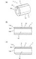
- FIG. 2 It is a perspective view which shows one Embodiment of the tracheostomy tube of this invention.
- A is an enlarged view of the distal end side of the tracheostomy tube of the present invention
- (b) is a longitudinal sectional view of the distal end side of the tracheostomy tube in FIG. 2 (a)
- (c) is It is a longitudinal cross-sectional view by the side of the distal end of a tracheostomy tube which shows the modification of the structure of the distal end of a tracheostomy tube. It is a figure which shows the extension part of the oxygen administration line of the tracheotomy tube of this invention.
- a tracheostomy tube 1 of the present invention is placed in a tracheostomy in a patient's neck (see FIG. 4), has a distal end 1d and a proximal end 1p, and is located on the distal end side. It has an opening Od and a proximal end side opening Op.
- the “distal end” refers to an end portion far from the practitioner when the tracheostomy tube 1 is inserted into the patient's trachea during the operation, that is, an end portion inserted into the trachea.
- the “end end” refers to an end on the side close to the practitioner when the tracheostomy tube 1 is inserted into the trachea of the patient during the operation, that is, an end on the side protruding from the patient's body.
- the tracheostomy tube 1 is provided on the inner side of the wall 11 extending from the distal end 1d to the proximal end 1p, and from the proximal end side opening Op to the distal end side opening Od. And a main pipeline 12 penetrating therethrough.
- the wall portion 11 is curved from the proximal end 1p to the distal end 1d, and is separated from the proximal end 1p by a certain distance toward the distal end 1d.
- a tracheostomy tube fixing wing 2 for fixing the tracheostomy tube 1 to the neck from the front side is provided.
- the tracheostomy tube fixing wing 2 fixes the tracheostomy tube 1 to the patient's neck, allows air to be taken into the lungs from the outside of the human body through the main conduit 12, and discharges the air exhaled from the lungs to the outside of the human body. can do.
- the tracheostomy tube 1 is not particularly limited as long as it is a hard material capable of maintaining its shape even when inserted into the trachea.
- the tracheostomy tube 1 of the present invention includes an oxygen administration conduit 3 for sending oxygen to the lung side, which is the distal end side.
- the oxygen administration line 3 is a path that forms a separate line from the main line 12 and is supplied with oxygen or a gas containing oxygen, and is supplied from an oxygen administration opening 31 formed on the distal end 1d side. Oxygen and oxygen-containing gas can be delivered to the patient's lungs.
- the oxygen administration pipe line 3 is provided integrally with the main pipe line 12.
- the oxygen administration pipe line 3 is formed inside the wall portion 11 and is provided integrally with the main pipe line 12. Can do.
- oxygen administration pipe line 3 is provided on the outer side or the inner side of the wall part 11 by being integrally formed with the wall part 11 or a separate oxygen administration pipe line 3 is fused to the wall part 11 by a known fixing method. It can also be provided integrally with the main pipeline 12.
- the distal end 3d of the oxygen administration line 3 is the distal end 11d of the wall 11 (see FIGS. 2B and 2C) or the main line 12.
- the distal end 12d (see FIGS. 2B and 2C) is provided at a position more distal than the distal ends.
- the distal end 11d of the wall 11 and the distal end 12d of the main conduit 12 are coincident, and the oxygen delivery conduit 3 is Although it is provided at the distal end 11d of the portion 11, the distal end 11d of the wall portion 11 is used when the distal end 11d of the wall portion 11 is tapered as shown in FIG.
- the present invention also includes the case where the distal end 12d of the main duct 12 is at a position (proximal end side) retracted from the bronchus.
- the oxygen administration pipe 3 is integrally provided inside the main pipe 12 as a separate body from the wall portion 11, the distal end 3 d of the oxygen administration pipe 3 is the distal end 12 d of the main pipe 12.
- the oxygen administration conduit 3 includes an extension portion 32 that extends further to the distal position side from the distal end 11 d of the wall portion 11 and the distal end 12 d of the main conduit 12. May be. The extension part 32 will be described later.
- oxygen administration line 3 By providing the oxygen administration line 3 separately from the main line 12 serving as a passage for exhalation and inhalation from the lungs of the patient, oxygen sent out through the oxygen administration line 3 or a gas containing oxygen can be obtained. As shown by the arrow in FIG. 4, a flow toward the bronchus direction is generated. While oxygen is being delivered from the oxygen administration line 3, this oxygen flow continues regardless of whether the patient exhales or inhales. Therefore, oxygen is sent deep into the trachea by the oxygen flow, and the oxygen administration efficiency is improved. Improved. Therefore, it is possible to easily obtain arterial oxygen saturation equivalent to that of a healthy person.
- the oxygen administration line 3 and the main line 12 are provided integrally, it is not necessary to insert a separate tube for supplying oxygen into the trachea. This reduces the risk of damaging the inner wall of the trachea and causing the patient to cough.
- the opening diameter of the oxygen administration opening 31 of the oxygen administration conduit 3 can be appropriately changed according to the size and shape of the tracheostomy tube 1 and is not particularly limited. From the viewpoint of feeding well, it is preferably in the range of 0.2 to 4 mm. Further, one or a plurality of oxygen administration pipes 3 may be provided.
- the oxygen delivery pipe 3 is provided with an extension 32, and an oxygen delivery opening 31 through which oxygen is delivered is located deeper in the trachea. As a result, the possibility of being sent out of the trachea can be further reduced.
- the length of the extension part 32 is not particularly limited, but is preferably 30 mm or less in order to reduce the possibility that the patient coughs when the extension part 32 bends and hits the tracheal wall.
- an oxygen administration hole 33 may be formed on the side surface of the extension portion 32. By forming the oxygen administration hole 33, oxygen can be continuously supplied even when the oxygen administration opening 31 is blocked by a viscous cough.
- the distal end 3d of the oxygen administration conduit 3 is located above the distal end opening Od when the tracheostomy tube 1 is placed in the tracheostomy. It is preferable to be provided as follows.
- the distal end 3d of the oxygen delivery line 3 that is, the oxygen delivery opening 31 above the distal end opening Od of the tracheostomy tube 1
- adhesiveness such as wrinkles generated in the trachea of the patient
- the secretion is less likely to adhere to the oxygen administration opening 31, and the oxygen administration opening 31 at the distal end 3d of the oxygen administration conduit 3 is not clogged by the adhesive secretion.
- the upper side of the distal end side opening Od means the upper half of the distal end side opening Od of the tracheostomy tube 1, that is, the half on the chest side of the patient.
- An oxygen administration opening 31 may be provided at the position.
- the proximal position side of the oxygen administration conduit 3 branches off from the proximal end side of the wall portion 11 to form a narrow tube 34, and an oxygen introduction connection portion 35 is provided at the tip of the narrow tube 34.
- the thin tube 34 is connected to an oxygen tube (not shown) via an oxygen introduction connecting portion 35, and oxygen fed from an oxygen supply device (not shown) is supplied to the oxygen tube and the oxygen introducing connection portion. 35, and sent to the oxygen administration line 3 through the thin tube 34.
- the thin tube 34 is a highly flexible tube, and the movement of the patient does not affect the tracheostomy tube 1 mechanically when the patient moves the neck while the thin tube 34 is connected to the oxygen administration line 3.
- the thin tube 34 has a bending resistance (flexibility) in the range of 30 to 200 mm as measured by a 45 ° cantilever measurement method specified in JIS L 1096. It is preferable. If the bending resistance is less than 30 mm, the tube may collapse when the tube is compressed. If the bending resistance is greater than 200 mm, the movement of the thin tube 34 is transmitted to the entire tracheostomy tube 1.
- This bending resistance is determined by using a known bending resistance tester (cantilever) in accordance with JIS ⁇ ⁇ L 1096 8.19.1 A method (45 ° cantilever method). This is a value obtained by extruding a predetermined test piece toward, and measuring the extruding distance at the other end when the center of the free end of the test piece is in contact with the inclined surface.
- the material of the thin tube 34 is not particularly limited as long as it is a non-toxic material used for medical purposes.
- a vinyl chloride resin, a silicon resin, or a polyolefin resin is used for a flexible tube for medical devices. Resins that can be used can be used.
- the length of the narrow tube 34 is not particularly limited as long as it can be supplied with oxygen and has a sufficient length in a state where the thin tube 34 is connected.
- the outer diameter of the thin tube 34 is not particularly limited as long as it has the flexibility described above.
- FIG. 5 shows a tracheostomy tube 10 according to another embodiment of the present invention.
- Components similar to those in the embodiment shown in FIG. 1 are denoted by the same reference numerals, and description of similar components is omitted.
- the tracheostomy tube 10 of the embodiment shown in FIG. 5 is an inflatable and contractible cuff provided on the outer periphery of the wall 11 near the distal end 11 d of the wall 11.
- a cuff air supply line 5 that communicates with the cuff 4 and is provided integrally with the main pipe line 12 and supplies air into the cuff 4, and a proximal portion of the wall 11 from the cuff air supply line 5.
- a cuff capillary 51 that branches from the end side, a pressure measurement bag 52 that is connected to the cuff capillary 51 and measures the pressure of the cuff 4, and a device (not shown) for supplying air to the cuff 4 are attached.
- a connector 53 provided with a backflow prevention valve.
- the tracheostomy tube 10 can be stably fixed in the trachea. Further, since the oxygen administration line 3 is provided integrally with the main line 12, even when the cuff 4 is provided, oxygen can be fed to the distal end side of the tracheostomy tube 10. , Can produce oxygen flow. Therefore, it is possible to easily obtain arterial oxygen saturation equivalent to that of a healthy person. Further, it is preferable that the cuff thin tube 51 has a bending resistance (flexibility) in a range of 30 to 200 mm as measured by a 45 ° cantilever measurement method specified in JIS L 1096.
- the cuff tubule 51 having such flexibility, even when the patient moves and the cuff tubule 51 moves, the movement of the cuff tubule 51 is directly applied to the wall 11 of the tracheostomy tube 10. I don't get it. Therefore, even when the patient moves his head greatly unconsciously, only the cuff tubule 51 moves, and the entire tracheostomy tube 10 is prevented from moving relative to the tracheostomy in the patient's tracheostomy. And the patient is prevented from coughing.
- FIG. 6 shows a tracheostomy tube 100 according to still another embodiment of the present invention.
- Components similar to those of the embodiment shown in FIGS. 1 and 5 are denoted by the same reference numerals, and description of similar components is omitted.
- the tracheostomy tube 100 of the embodiment shown in FIG. 6 further includes a suction conduit 6 for sucking sticky secretions such as sputum in the trachea, and a wall from the suction conduit 6.
- a suction thin tube 61 branched from the proximal end side of the portion 11 and a suction thin tube connection connector 62 for connection to a suction device (not shown) are provided.
- the suction line 6 is provided integrally with the main line 12, and even when the cuff 4 is provided, an adhesive secretion such as a sputum can be sucked from the distal end side of the tracheostomy tube 100. it can.
- the position where the suction conduit 6 is provided is not particularly limited, but when the tracheostomy tube 100 is placed in the tracheostomy part in order to efficiently suck the adhesive secretion, the distal end side of the tracheostomy tube 100 is located. It is preferable to provide in the lower half of the opening Od.
- the lower half of the distal end opening Od of the tracheostomy tube 100 refers to the half of the tracheostomy tube 100 on the patient's back side.
- the suction thin tube 61 preferably has a bending resistance (flexibility) in the range of 30 to 200 mm as measured by a 45 ° cantilever measurement method specified in JIS L 1096.
- the examples and comparative examples were performed by the same patient (women in the 80s). This patient has undergone a tracheostomy 6 months ago and is undergoing medical treatment and has reduced pulmonary function, thus maintaining arterial oxygen saturation and maintaining breathing in room air with oxygen discontinuation The oxygen saturation at that time was 80%.
- Example An oxygen administration conduit having an inner diameter of 2.2 mm is formed in the wall of a commercially available tracheostomy tube, an extension portion of 15 mm is provided from the distal end of the tracheostomy tube, and an oxygen administration opening is provided at the tip of the extension portion. Part was formed.
- the oxygen administration line was formed so as to be located at the top when placed in the tracheostomy.
- the thin tube connected to the oxygen administration line was made of soft vinyl chloride having a bending resistance of 55 mm by a cantilever measurement method having an inner diameter of 2.00 mm and an outer diameter of 3.33 mm. Other than that, it formed similarly to the structure shown in FIG.
- a thin tube extending from the oxygen administration line was connected to the oxygen tube to supply 0.5 liter of oxygen per minute.
- the arterial blood oxygen saturation of the patient was measured with a pulse oximeter (manufactured by Konica Minolta, product name: oxygen saturation monitor PULSOX-300).
- the clogging of the main pipeline was visually observed.
- the movement of the entire tracheostomy tube at the tracheostomy when the head was moved was observed.
- arterial oxygen saturation increased from 80% to 98% by supplying 0.5 liters of oxygen per minute.
- the tracheostomy tube was placed in the patient's tracheostomy for 5 days, and then the tracheostomy tube was replaced.
- the main tracheostomy tube after use was almost stenotic due to viscous wrinkles. Further, when the patient moved his / her head, the tracheostomy tube did not move relative to the tracheostomy, and was stably placed.
- Comparative Example 1 A commercially available tracheostomy tube (Portex, product name: uncuffed tracheostomy tube 100/506/080) without an oxygen administration conduit is used, and the proximal end side opening of this tracheostomy tube is used. Attach an artificial nose, connect an oxygen tube made of soft vinyl chloride having a bending resistance of 250 mm with a cantilever measurement method with an inner diameter of 3.00 mm and an outer diameter of 4.00 mm to supply 3 liters of oxygen per minute. The arterial oxygen saturation was measured in the same manner as in the examples. Thereafter, the oxygen supply amount was increased to 5 liters per minute, and the arterial oxygen saturation was measured again. At the same time, the clogging of the main pipeline was visually observed. In addition, the movement of the entire tracheostomy tube at the tracheostomy when the head was moved was observed.
- Comparative Example 1 the arterial oxygen saturation increased from 80% to 90% by supplying 3 liters of oxygen per minute. When supplying 5 liters of oxygen per minute, arterial oxygen saturation remained 90%.
- the degree of clogging of the tracheostomy tube is once every 2 to 3 days, and the lumen diameter of the main duct is narrowed from 8 mm to 4.5 mm due to wrinkles. Decreased to 80%.
- the entire tracheostomy tube moved relative to the tracheostomy, showing a reflection that the patient coughed.
- Comparative Example 2 A joint formed from a hard resin was attached to the proximal end side opening of the tracheostomy tube without attaching an artificial nose to the tracheostomy tube similar to Comparative Example 1, and the main conduit and the joint were connected in an airtight manner.
- An oxygen tube made of soft vinyl chloride having a bending resistance of 250 mm by a cantilever measurement method having an inner diameter of 3.00 mm and an outer diameter of 4.00 mm is hermetically connected to the joint attached to the main pipeline, and oxygen is directly contained in the main pipeline.
- This tracheostomy tube was supplied with 3 liters of oxygen per minute, and the arterial oxygen saturation was measured in the same manner as in Example and Comparative Example 1.
- the oxygen supply was increased to 5 liters per minute to measure arterial oxygen saturation, and then the oxygen supply was increased to 8 liters per minute to measure arterial oxygen saturation.
- the clogging of the main pipeline was visually observed.
- the movement of the entire tracheostomy tube at the tracheostomy when the head was moved was observed.
- the oxygen administration line can maintain the arterial oxygen saturation at the same level as the arterial oxygen saturation of a healthy person, whereas in the comparative example, the main line is It has been found that clogging reduces arterial oxygen saturation and coughs.
- the thin tube is flexible, even if the patient moves his head unconsciously, the thin tube can flexibly follow the movement of the tracheostomy tube, and the movement of the head does not affect the tracheostomy tube.
- Comparative Examples 1 and 2 it was found that the oxygen tube was affected by the movement of the tracheostomy tube, and the tracheostomy tube moved by the movement of the head, causing the patient to cough.
Abstract
遠位端1dと近位端1pとを有し、気管切開部に留置する気管切開チューブ1であって、遠位端側開口部Odと近位端側開口部Opとを有し、遠位端1dから近位端1pへと延びる壁部11と、壁部11の内側に設けられ、近位端側開口部Opから遠位端側開口部Odへ貫通する主管路12と、遠位端1d側に酸素を導入するための酸素投与管路3とを備え、酸素投与管路3が主管路12と一体的に設けられ、酸素投与管路3の遠位端3dが、壁部11の遠位端11d、若しくは主管路12の遠位端12d、またはこれらの遠位端よりも遠位位置に設けられた気管切開チューブを用いることで、患者に対して、過度な負担が無く、投与した酸素により、健常人の動脈血酸素飽和度と同程度の動脈血酸素飽和度を容易に与えることができる。
Description
本発明は、患者に対して過度な負担が無く、投与した酸素により、健常人の動脈血酸素飽和度と同程度の動脈血酸素飽和度を容易に得ることができる気管切開チューブに関する。
気道確保が困難となった患者では一般的に気管切開が行われ、気管切開カニューレが患者の頚部に留置される。患者の呼吸状況が悪化し自発呼吸が困難で低酸素状態に陥れば該気管切開カニューレに人工呼吸器を連結し高濃度の酸素を送り込む治療が行われる。しかし自発呼吸があるものの呼吸機能低下の酸素が不足した患者では該気管切開カニューレに連結された人工鼻部分に酸素を送り込む処置をすることが一般的である。
このような気管切開チューブとして、特許文献1には、図7に示すように、中央管腔500によって呼吸用空気の供給と排出を行ない、チューブ510の外部に開口する吸引導管520、およびカフ530の上流でチューブ510の外部にまた開口する供給導管540を備えた気管切開チューブが開示されている。吸引導管520により、気管内に蓄積した流体や粘液を吸引する。また、カフ530の上流で供給導管540を経由してリンスまたはフラッシュ流体を、気管内にスプレーし、バクテリアやその他の細菌を除去する。患者の呼吸は、カフ530の下流に開口した中央管腔500により行われ、吸引導管520や供給導管540は、カフ530の上流側において、チューブ510の外周側に開口している。チューブ510の気管の外側に位置することになる端部には、標準アダプタ550が設けられ、人工呼吸器や麻酔装置に接続可能となっている。
このような人工呼吸器に接続される気管切開カニューレでは、通常、気管切開カニューレの基端部側に人工鼻(図示せず)を設け、その人工鼻に酸素を送り込むが、人工鼻部分は外気に解放されているので、呼気時には投与された酸素は気管内に入らず、送られた酸素の一部のみが、吸気時に気管内に吸い込まれる、というのが実情であり、酸素投与効率が悪いという問題があった。
酸素投与効率が悪くなると、患者の動脈血酸素飽和度が下がり、低酸素血症状態となってしまう。また、酸素投与用のチューブ等を、別途気管内に挿入すると、患者が咳き込んだりする危険性が高まり、患者への負担が大きくなってしまう。
そこで、本発明は、かかる問題点に鑑みて、患者に対して、過度な負担が無く、投与した酸素により、健常人の動脈血酸素飽和度と同程度の動脈血酸素飽和度を容易に得ることができる気管切開チューブを提供することを目的とする。
本発明の気管切開チューブは、遠位端と近位端とを有し、気管切開部に留置する気管切開チューブであって、遠位端側開口部と近位端側開口部とを有し、前記遠位端から前記近位端へと延びる壁部と、前記壁部の内側に設けられ、前記近位端側開口部から前記遠位端側開口部へ貫通する主管路と、前記遠位端側に酸素を導入するための酸素投与管路とを備え、前記酸素投与管路が前記主管路と一体的に設けられ、前記酸素投与管路の遠位端が、前記壁部の遠位端、若しくは前記主管路の遠位端、またはこれらの遠位端よりも遠位位置に設けられたことを特徴とする。
また、前記酸素投与管路の遠位端が、前記気管切開チューブを前記気管切開部に留置した際に、前記遠位端側開口部の上側となるように設けられることが好ましい。
また、前記酸素投与管路の近位位置側は、前記壁部の近位端側から分岐して細管を構成し、前記細管の先端に酸素導入用接続部が形成されて、前記細管はカンチレバー測定法で30mm~200mmの範囲の柔軟性を持つことが好ましい。
本発明によれば、酸素投与管路が前記主管路と一体的に設けられているので、患者に対して過度な負担が無く、酸素投与管路の遠位端が、前記管壁の遠位端、または前記管路の遠位端よりも遠位位置に設けられているので、健常人の動脈血酸素飽和度と同程度の動脈血酸素飽和度を容易に得ることができる。
また、酸素投与管路の遠位端が、前記気管切開チューブを前記気管切開部に留置した際に、前記遠位端開口部の上側となるように設けられているので、酸素投与管路の遠位端が痰で詰まることがない。
また、患者が無意識下で頭を大きく動かした時であっても、患者は咳き込むことが抑制される。
以下、添付図面を参照し、本発明の気管切開チューブを詳細に説明する。
図1に示すように、本発明の気管切開チューブ1は、患者の頚部における気管切開部に留置され(図4参照)、遠位端1dと近位端1pとを有し、遠位端側開口部Odと近位端側開口部Opとを有している。なお、「遠位端」とは、施術において患者の気管に気管切開チューブ1を挿入する際の施術者から遠い側の端部、すなわち気管内に挿入される側の端部をいい、「近位端」とは、施術において患者の気管に気管切開チューブ1を挿入する際の施術者に近い側の端部、すなわち患者の体外に突出する側の端部をいう。
また、気管切開チューブ1は、遠位端1dから近位端1pへと延びる壁部11と、壁部11の内側に設けられ、近位端側開口部Opから遠位端側開口部Odへ貫通する主管路12とを備えている。壁部11は、図1に示すように、近位端1pから遠位端1dにかけて湾曲して形成され、近位端1pから一定距離だけ遠位端1d側に離れた位置に、患者の体表側から気管切開チューブ1を頚部に固定するための気管切開チューブ固定翼2が設けられている。気管切開チューブ固定翼2により、患者の頚部に気管切開チューブ1が固定され、主管路12を通じて、人体の外部から肺へ空気を取り入れることができるとともに、肺から吐き出された空気を人体外部に吐出することができる。なお、気管切開チューブ1は、気管に挿入しても形状の維持が可能な硬質の材料であれば特に限定されるものではない。
本発明の気管切開チューブ1には、図1に示すように、遠位端側である肺側に酸素を送り込むための酸素投与管路3を備えている。酸素投与管路3は、主管路12とは別々の管路を形成し、酸素や酸素を含む気体が供給される通路であり、遠位端1d側に形成された酸素投与開口部31から供給された酸素や酸素を含む気体を患者の肺に送り込むことができる。酸素投与管路3は、主管路12と一体的に設けられ、たとえば、図1に示すように、壁部11の内部に酸素投与管路3を形成して主管路12と一体的に設けることができる。また、壁部11の外側や内側に、酸素投与管路3を壁部11と一体成形により設けたり、別体の酸素投与管路3を壁部11に融着するなど、公知の固着方法により主管路12と一体的に設けることもできる。
酸素投与管路3の遠位端3d(図2(b)および(c)参照)は、壁部11の遠位端11d(図2(b)および(c)参照)、若しくは主管路12の遠位端12d(図2(b)および(c)参照)、またはこれらの遠位端よりも遠位位置に設けられる。図1、図2(a)および(b)に示す実施形態では、壁部11の遠位端11dと主管路12の遠位端12dとが一致しており、酸素投与管路3は、壁部11の遠位端11dに設けられているが、図2(c)に示すように、壁部11の遠位端11dがテーパ状となっている場合等、壁部11の遠位端11dが、主管路12の遠位端12dよりも、気管支から後退した位置(近位端側)にある場合も本発明に含まれる。また、壁部11とは別体として、主管路12の内側に酸素投与管路3を一体的に設けた場合に、酸素投与管路3の遠位端3dは主管路12の遠位端12dに位置し、このような態様も本発明に含まれる。また、図3に示す実施形態では、酸素投与管路3が、壁部11の遠位端11dおよび主管路12の遠位端12dからさらに遠位位置側に延出する延出部32を備えてもよい。なお、延出部32については後述する。
酸素投与管路3が、患者の肺からの呼気、吸気の通路となる主管路12とは別に設けられることにより、酸素投与管路3を通って送りだされる酸素、または酸素を含む気体は、図4に矢印で示すように気管支方向に向かう流れを生み出す。酸素投与管路3から酸素を送り出している間は、患者の呼気時、吸気時を問わず、この酸素の流れが継続するため、酸素流によって気管内深くまで酸素が送り込まれ、酸素投与効率が改善される。したがって、健常人の動脈血酸素飽和度と同程度の動脈血酸素飽和度を容易に得ることができる。また、酸素投与管路3と主管路12とが一体的に設けられているので、別途酸素を供給するためのチューブを気管内に挿入することが不要であり、複数のチューブにより患者の気管内で気管内壁を傷つけたり、チューブによって患者が咳き込んだりする危険性が低くなる。
酸素投与管路3の酸素投与開口部31の開口径は、気管切開チューブ1の大きさや形状に応じて適宜変更が可能であり、特に限定されるものではないが、気管の奥深くまで酸素を効率よく送りこむ観点から、0.2~4mmの範囲であることが好ましい。また、酸素投与管路3の数は、1つでも複数設けても構わない。
また、図3に示すように、酸素投与管路3に延出部32を設け、気管内のより奥深い位置に酸素が送り出される酸素投与開口部31を位置させることにより、送付された酸素が呼気として気管外に送り出される可能性をより低くすることができる。延出部32の長さは特に限定されるものではないが、延出部32が撓んで気管壁に当たることにより患者が咳き込む可能性を低くするために、30mm以下とすることが好ましい。また、図3に示すように、延出部32の先端の酸素投与開口部31以外に、延出部32の側面に酸素投与孔33を形成してもよい。酸素投与孔33を形成することにより、酸素投与開口部31が粘調な咳痰により閉塞した場合であっても、酸素を供給し続けることができる。
また、図1および図2(a)に示すように、酸素投与管路3の遠位端3dは、気管切開チューブ1を気管切開部に留置した際に、遠位端側開口部Odの上側となるように設けることが好ましい。酸素投与管路3の遠位端3d、すなわち、酸素投与開口部31を気管切開チューブ1の遠位端側開口部Odの上側に設けることにより、患者の気管内で発生した痰などの粘着性分泌物が酸素投与開口部31に付着しにくくなり、酸素投与管路3の遠位端3dの酸素投与開口部31が粘着性分泌物により詰まることがない。なお、遠位端側開口部Odの上側とは、気管切開チューブ1の遠位端側開口部Odの上半分、すなわち、患者の胸部側の半分のことをいい、上半分であれば、どの位置に酸素投与開口部31が設けられていてもよい。
また、図1に示すように、酸素投与管路3の近位位置側は、壁部11の近位端側から分岐して細管34を構成し、細管34の先端に酸素導入用接続部35を形成することができる。細管34は、酸素導入用接続部35を介して、酸素チューブ(図示せず)と接続され、酸素を供給する装置(図示せず)から送り込まれた酸素が、酸素チューブ、酸素導入用接続部35、細管34を介して、酸素投与管路3に送り込まれる。
細管34は、柔軟性の高い管とし、細管34が酸素投与管路3に連結された状態で、患者が頚部を動かしたときに患者の動きが気管切開チューブ1に力学的な影響を与えない程度の柔軟性を有することが好ましく、たとえば、細管34が、JIS L 1096に規定する45°カンチレバー測定法で測定して、30~200mmの範囲の剛軟度(柔軟性)を持つようにすることが好ましい。剛軟度が30mmより小さいと、管が圧迫されたときに管がつぶれる可能性があり、200mmより大きいと、細管34の動きが気管切開チューブ1全体に動きが伝わってしまう。この剛軟度(柔軟性)は、公知の剛軟度試験機(カンチレバー)を用いて、JIS L 1096 8.19.1 A法(45°カンチレバー法)に準拠して、45°の傾斜面に向かって所定の試験片を押し出し、試験片自由端の中央が傾斜面に接したときの他端の押し出し距離を測定することにより得られた値である。このような柔軟性を有する細管34を用いることにより、患者が動いて細管34が動いた場合であっても、細管34の動きが気管切開チューブ1の壁部11に直接伝わらない。したがって、長時間の使用によって、患者が無意識下で頭を大きく動かした時であっても、細管34のみが動き、患者の気管切開部において気管切開チューブ1全体が気管切開部に対して動くことを防止することができ、患者は咳き込むことが抑制される。
細管34の材料は、医療用に用いられる毒性のないものであれば特に限定されないが、たとえば、塩化ビニル系樹脂、シリコン系樹脂、またはポリオレフィン系樹脂等をの医療機器用の柔軟なチューブに用いるができる樹脂を用いることができる。また、細管34の長さは、酸素が供給でき、細管34が接続された状態で、余裕のある長さであれば特に限定されない。また、細管34の外径は、上述したような柔軟性があれば特に限定されない。
図5に本発明の他の実施形態の気管切開チューブ10を示す。図1に示す実施形態と同様の構成については同じ参照符号を付し、同様の構成については説明を省略する。
図5に示す実施形態の気管切開チューブ10は、図1に示す実施形態の構成に加えて、壁部11の遠位端11d近傍において、壁部11の外周に設けられる膨張、収縮可能なカフ4と、カフ4に連通し、主管路12と一体的に設けられた、カフ4内に送気するためのカフ用送気管路5と、カフ用送気管路5から壁部11の近位端側から分岐するカフ用細管51と、カフ用細管51に接続され、カフ4の圧力を測定するための圧力測定バッグ52と、カフ4に送気するための装置(図示せず)に取り付けるための、逆流防止弁が設けられたコネクタ53とを備えている。
図5に示す実施の形態では、カフ4が設けられているため、気管切開チューブ10を気管内に安定して固定することができる。また、酸素投与管路3が、主管路12と一体的に設けられているので、カフ4を設けた場合であっても、気管切開チューブ10の遠位端側に、酸素を送り込むことができ、酸素流を生み出すことができる。したがって、健常人の動脈血酸素飽和度と同程度の動脈血酸素飽和度を容易に得ることができる。また、カフ用細管51は、JIS L 1096に規定する45°カンチレバー測定法で測定して、30~200mmの範囲の剛軟度(柔軟性)を持つようにすることが好ましい。このような柔軟性を有するカフ用細管51を用いることにより、患者が動いてカフ用細管51が動いた場合であっても、カフ用細管51の動きが気管切開チューブ10の壁部11に直接伝わらない。したがって、患者が無意識下で頭を大きく動かした時であっても、カフ用細管51のみが動き、患者の気管切開部において気管切開チューブ10全体が気管切開部に対して動くことを防止することができ、患者は咳き込むことが抑制される。
図6に本発明のさらに他の実施形態の気管切開チューブ100を示す。図1および図5に示す実施形態と同様の構成については同じ参照符号を付し、同様の構成については説明を省略する。
図6に示す実施形態の気管切開チューブ100は、図5の実施形態に加えて、さらに気管内の痰などの粘着性分泌物を吸引する吸引用管路6と、吸引用管路6から壁部11の近位端側から分岐する吸引用細管61と、吸引装置(図示せず)に接続するための吸引用細管接続コネクタ62とを備えている。吸引用管路6は、主管路12と一体的に設けられ、カフ4を設けた場合であっても、気管切開チューブ100の遠位端側から痰などの粘着性分泌物を吸引することができる。吸引用管路6を設ける位置は、特に限定されないが、粘着性分泌物を効率よく吸引するために、気管切開チューブ100を気管切開部に留置した際に、気管切開チューブ100の遠位端側開口部Odの下半分に設けることが好ましい。なお、気管切開チューブ100の遠位端側開口部Odの下半分とは、気管切開チューブ100における患者の背中側の半分をいうものである。
吸引用細管61は、JIS L 1096に規定する45°カンチレバー測定法で測定して、30~200mmの範囲の剛軟度(柔軟性)を持つようにすることが好ましい。このような柔軟性を有する吸引用細管61を用いることにより、患者が動いて吸引用細管61が動いた場合であっても、吸引用細管61の動きが気管切開チューブ100の壁部11に直接伝わらない。したがって、長時間の使用において、患者が無意識下で頭を大きく動かした時であっても、吸引用細管61のみが動き、患者の気管切開部において気管切開チューブ100全体が気管切開部に対して動くことを防止することができ、患者は咳き込むことが抑制される。
つぎに、実施例および比較例を参照し、本発明を具体的に説明するが、本発明はこれらのみに限定されるものではない。
実施例および比較例は、同一の患者(80歳台の女性)により行った。この患者は、気管切開処置を6ヶ月前に受け、療養中であり、肺機能が低下しているため、動脈血酸素飽和度が低く、酸素投与が中止された状態で、室内空気で呼吸を維持した時の酸素飽和度は80%であった。
実施例
市販の気管切開チューブの壁部内に、内径2.2mmの酸素投与管路を形成し、気管切開チューブの遠位端から15mmの延出部を設け、延出部の先端に酸素投与開口部を形成した。酸素投与管路は、気管切開部に留置されたときに最上部に位置するように形成した。酸素投与管路に連通する細管は、内径2.00mm、外径3.33mmのカンチレバー測定法で55mmの剛軟度を有する軟質塩化ビニル製のものを用いた。それ以外は、図1に示す構造と同様に形成した。この気管切開チューブを用いて、酸素投与管路から延びる細管を酸素チューブに連結し、毎分0.5リットルの酸素を供給した。このときの患者の動脈血酸素飽和度をパルスオキシメーター(コニカミノルタ社製、製品名:酸素飽和モニターPULSOX-300)により測定した。同時に主管路の詰まり具合を目視により観察した。また、頭を動かしたときの気管切開部における気管切開チューブ全体の動きを観察した。
市販の気管切開チューブの壁部内に、内径2.2mmの酸素投与管路を形成し、気管切開チューブの遠位端から15mmの延出部を設け、延出部の先端に酸素投与開口部を形成した。酸素投与管路は、気管切開部に留置されたときに最上部に位置するように形成した。酸素投与管路に連通する細管は、内径2.00mm、外径3.33mmのカンチレバー測定法で55mmの剛軟度を有する軟質塩化ビニル製のものを用いた。それ以外は、図1に示す構造と同様に形成した。この気管切開チューブを用いて、酸素投与管路から延びる細管を酸素チューブに連結し、毎分0.5リットルの酸素を供給した。このときの患者の動脈血酸素飽和度をパルスオキシメーター(コニカミノルタ社製、製品名:酸素飽和モニターPULSOX-300)により測定した。同時に主管路の詰まり具合を目視により観察した。また、頭を動かしたときの気管切開部における気管切開チューブ全体の動きを観察した。
本実施例では、毎分0.5リットルの酸素を供給することにより、動脈血酸素飽和度が、80%から98%に上昇した。また、患者の気管切開部に5日間気管切開チューブを留置した後、気管切開チューブを交換し、使用後の気管切開チューブの主管路は、粘調な痰により半分近く狭窄していた。また、患者が頭を動かした場合に、気管切開チューブは、気管切開部に対して動くことがなく、安定して留置されていた。
比較例1
市販されている酸素投与管路が設けられていない気管切開チューブ(Portex社製、製品名:カフなし気管切開チューブ100/506/080)を用い、この気管切開チューブの近位端側開口部に人工鼻を取り付け、人工鼻に内径3.00mm、外径4.00mmのカンチレバー測定法で250mmの剛軟度を有する軟質塩化ビニル製の酸素チューブを接続し、毎分3リットルの酸素を供給し、実施例と同様の方法で動脈血酸素飽和度を測定した。その後、毎分5リットルに酸素の供給量を増やし、再び動脈血酸素飽和度を測定した。同時に主管路の詰まり具合を目視により観察した。また、頭を動かしたときの気管切開部における気管切開チューブ全体の動きを観察した。
市販されている酸素投与管路が設けられていない気管切開チューブ(Portex社製、製品名:カフなし気管切開チューブ100/506/080)を用い、この気管切開チューブの近位端側開口部に人工鼻を取り付け、人工鼻に内径3.00mm、外径4.00mmのカンチレバー測定法で250mmの剛軟度を有する軟質塩化ビニル製の酸素チューブを接続し、毎分3リットルの酸素を供給し、実施例と同様の方法で動脈血酸素飽和度を測定した。その後、毎分5リットルに酸素の供給量を増やし、再び動脈血酸素飽和度を測定した。同時に主管路の詰まり具合を目視により観察した。また、頭を動かしたときの気管切開部における気管切開チューブ全体の動きを観察した。
比較例1では、毎分3リットルの酸素を供給することにより、動脈血酸素飽和度が、80%から90%に上昇した。毎分5リットルの酸素を供給すると、動脈血酸素飽和度は90%のままであった。また、気管切開チューブの詰まり具合は、2~3日に一度の頻度で、主管路の内腔径が痰により8mmから4.5mm程度にまで狭窄し、酸素を供給しても動脈血酸素飽和度が80%まで下がった。また、患者が頭を動かしたときに、気管切開部に対して気管切開チューブ全体が動き、患者が咳き込む反射を示した。
比較例2
比較例1と同様の気管切開チューブに、人工鼻を取り付けずに、気管切開チューブの近位端側開口部に、硬質樹脂から形成したジョイントを取り付け、主管路とジョイントを気密に連結した。主管路に取り付けられたジョイントにさらに内径3.00mm、外径4.00mmのカンチレバー測定法で250mmの剛軟度を有する軟質塩化ビニル製の酸素チューブを気密に連結し、主管路内に直接酸素を送り込むようにした。この気管切開チューブに、毎分3リットルの酸素を供給し、実施例、比較例1と同様の方法で、動脈血酸素飽和度を測定した。その後、毎分5リットルに酸素の供給量を増やし、動脈血酸素飽和度を測定し、その後に毎分8リットルに酸素の供給量を増やして、動脈血酸素飽和度を測定した。同時に主管路の詰まり具合を目視により観察した。また、頭を動かしたときの気管切開部における気管切開チューブ全体の動きを観察した。
比較例1と同様の気管切開チューブに、人工鼻を取り付けずに、気管切開チューブの近位端側開口部に、硬質樹脂から形成したジョイントを取り付け、主管路とジョイントを気密に連結した。主管路に取り付けられたジョイントにさらに内径3.00mm、外径4.00mmのカンチレバー測定法で250mmの剛軟度を有する軟質塩化ビニル製の酸素チューブを気密に連結し、主管路内に直接酸素を送り込むようにした。この気管切開チューブに、毎分3リットルの酸素を供給し、実施例、比較例1と同様の方法で、動脈血酸素飽和度を測定した。その後、毎分5リットルに酸素の供給量を増やし、動脈血酸素飽和度を測定し、その後に毎分8リットルに酸素の供給量を増やして、動脈血酸素飽和度を測定した。同時に主管路の詰まり具合を目視により観察した。また、頭を動かしたときの気管切開部における気管切開チューブ全体の動きを観察した。
比較例2では、毎分3リットルの酸素を供給することにより、動脈血酸素飽和度が、80%から93%に上昇した。毎分5リットルの酸素を供給すると、動脈血酸素飽和度は93%から94%に上昇した。毎分8リットルの酸素を供給すると、動脈血酸素飽和度は94%のままであった。また、気管切開チューブの詰まり具合は、比較例1と同様に2~3日に一度の頻度で、主管路の内腔径が痰により8mmから4.5mm程度にまで狭窄し、酸素を供給しても動脈血酸素飽和度が80%まで下がった。また、患者が頭を動かしたときに、気管切開部に対して気管切開チューブ全体が動き、患者が咳き込む反射を示した。
上記の実施例、比較例1および2から、酸素投与管路が設けられた実施例では毎分0.5リットルという少量の酸素で動脈血酸素飽和度を98%という高い値まで上げることができ、酸素投与の効率がよいのに対し、比較例の主管路から酸素を供給する気管切開チューブでは、実施例よりも遥かに多い量の酸素が必要であり、酸素投与の効率が悪く、酸素の量を増やしていっても、98%という高い動脈血酸素飽和度が得られないことがわかった。
また、実施例では、主管路が詰まった場合でも、酸素投与管路により、動脈血酸素飽和度を健常人の動脈血酸素飽和度と同程度の数値を維持できるのに対し、比較例では主管路が詰まることにより、動脈血酸素飽和度が低下し、咳き込んでしまうことがわかった。
また、実施例では、細管が柔軟であることにより、患者が無意識下で頭を大きく動かしても、細管が気管切開チューブの動きに柔軟に追従し、頭の動きが気管切開チューブに影響しないのに対し、比較例1および2では、酸素チューブが気管切開チューブの動きに影響され、頭の動きにより気管切開チューブが動き、患者が咳き込む原因となることがわかった。
1、10、100 気管切開チューブ
1d 遠位端
1p 近位端
11 壁部
11d 遠位端
12 主管路
12d 遠位端
2 気管切開チューブ固定翼
3 酸素投与管路
3d 遠位端
31 酸素投与開口部
32 延出部
33 酸素投与孔
34 細管
35 酸素導入用接続部
4 カフ
5 カフ用送気管路
51 カフ用細管
52 圧力測定バッグ
53 コネクタ
6 吸引用管路
61 吸引用細管
62 吸引用細管接続コネクタ
Od 遠位端側開口部
Op 近位端側開口部
1d 遠位端
1p 近位端
11 壁部
11d 遠位端
12 主管路
12d 遠位端
2 気管切開チューブ固定翼
3 酸素投与管路
3d 遠位端
31 酸素投与開口部
32 延出部
33 酸素投与孔
34 細管
35 酸素導入用接続部
4 カフ
5 カフ用送気管路
51 カフ用細管
52 圧力測定バッグ
53 コネクタ
6 吸引用管路
61 吸引用細管
62 吸引用細管接続コネクタ
Od 遠位端側開口部
Op 近位端側開口部
Claims (3)
- 遠位端と近位端とを有し、気管切開部に留置する気管切開チューブであって、
遠位端側開口部と近位端側開口部とを有し、
前記遠位端から前記近位端へと延びる壁部と、
前記壁部の内側に設けられ、前記近位端側開口部から前記遠位端側開口部へ貫通する主管路と、
前記遠位端側に酸素を導入するための酸素投与管路とを備え、
前記酸素投与管路が前記主管路と一体的に設けられ、
前記酸素投与管路の遠位端が、前記壁部の遠位端、若しくは前記主管路の遠位端、またはこれらの遠位端よりも遠位位置に設けられた気管切開チューブ。 - 前記酸素投与管路の遠位端が、前記気管切開チューブを前記気管切開部に留置した際に、前記遠位端側開口部の上側となるように設けられた請求項1記載の気管切開チューブ。
- 前記酸素投与管路の近位位置側は、前記壁部の近位端側から分岐して細管を構成し、前記細管の先端に酸素導入用接続部が形成されて、前記細管はカンチレバー測定法で30mm~200mmの範囲の柔軟性を持つことを特徴とする請求項1または2記載の気管切開チューブ。
Priority Applications (1)
| Application Number | Priority Date | Filing Date | Title |
|---|---|---|---|
| PCT/JP2013/061828 WO2014174582A1 (ja) | 2013-04-23 | 2013-04-23 | 気管切開チューブ |
Applications Claiming Priority (1)
| Application Number | Priority Date | Filing Date | Title |
|---|---|---|---|
| PCT/JP2013/061828 WO2014174582A1 (ja) | 2013-04-23 | 2013-04-23 | 気管切開チューブ |
Publications (1)
| Publication Number | Publication Date |
|---|---|
| WO2014174582A1 true WO2014174582A1 (ja) | 2014-10-30 |
Family
ID=51791193
Family Applications (1)
| Application Number | Title | Priority Date | Filing Date |
|---|---|---|---|
| PCT/JP2013/061828 WO2014174582A1 (ja) | 2013-04-23 | 2013-04-23 | 気管切開チューブ |
Country Status (1)
| Country | Link |
|---|---|
| WO (1) | WO2014174582A1 (ja) |
Citations (2)
| Publication number | Priority date | Publication date | Assignee | Title |
|---|---|---|---|---|
| JP2002532206A (ja) * | 1998-12-22 | 2002-10-02 | レスピロニクス・インコーポレイテッド | 気管内気体吹送装置、吹送付属装置及び吹送気体供給法 |
| JP2013085900A (ja) * | 2011-10-21 | 2013-05-13 | Hi-Lex Corporation | 気管切開チューブ |
-
2013
- 2013-04-23 WO PCT/JP2013/061828 patent/WO2014174582A1/ja active Application Filing
Patent Citations (2)
| Publication number | Priority date | Publication date | Assignee | Title |
|---|---|---|---|---|
| JP2002532206A (ja) * | 1998-12-22 | 2002-10-02 | レスピロニクス・インコーポレイテッド | 気管内気体吹送装置、吹送付属装置及び吹送気体供給法 |
| JP2013085900A (ja) * | 2011-10-21 | 2013-05-13 | Hi-Lex Corporation | 気管切開チューブ |
Similar Documents
| Publication | Publication Date | Title |
|---|---|---|
| EP1188457B1 (en) | Oro/nasopharyngeal airway | |
| AU2014228824B2 (en) | Medical breathing apparatus | |
| US4584998A (en) | Multi-purpose tracheal tube | |
| US5937858A (en) | Oro/nasopharyngeal airway for administering/sampling inhalent/expired gases | |
| US6860264B2 (en) | Method and apparatus for endotracheal intubation using a light wand and curved guide | |
| JP2009508645A5 (ja) | ||
| US20080223375A1 (en) | Single nasal prong nasal cannula | |
| CN109068961B (zh) | 医用气体输送系统 | |
| US11285287B2 (en) | Tracheostomy or endotracheal tube adapter for speech | |
| CN111526912B (zh) | 具有优异通气能力,并具有将支气管内导管准确放置在期望支气管中的系统的气管插管促进器 | |
| US11478596B2 (en) | System and method for high flow oxygen therapy | |
| CN106880897A (zh) | 一种麻醉导管 | |
| JP2013085900A (ja) | 気管切開チューブ | |
| US20170203066A1 (en) | Tracheostomy or endotracheal tube adapter for speech | |
| WO2014174582A1 (ja) | 気管切開チューブ | |
| CN112807537A (zh) | 一种供氧及吸痰管及具有其的节律性供氧及吸痰系统 | |
| KR20150005827A (ko) | 내시경용 기도유지장치 | |
| CN208511669U (zh) | 一种可持续气道内吸引的气管导管 | |
| CN110732069A (zh) | 可进行食道引流的气管插管 | |
| CN215135195U (zh) | 一种可通氧的通气道 | |
| CN113262384B (zh) | 气管表面麻醉器械 | |
| CN111632245B (zh) | 一种可实施喉部舒缓麻醉的气管插管 | |
| CN215840992U (zh) | 一种供氧及吸痰管及具有其的节律性供氧及吸痰系统 | |
| US20220096777A1 (en) | Breath sensing with remote pressure sensor | |
| CN208525606U (zh) | 扩张支撑型鼻咽通气道 |
Legal Events
| Date | Code | Title | Description |
|---|---|---|---|
| 121 | Ep: the epo has been informed by wipo that ep was designated in this application |
Ref document number: 13883157 Country of ref document: EP Kind code of ref document: A1 |
|
| NENP | Non-entry into the national phase |
Ref country code: DE |
|
| 122 | Ep: pct application non-entry in european phase |
Ref document number: 13883157 Country of ref document: EP Kind code of ref document: A1 |
|
| NENP | Non-entry into the national phase |
Ref country code: JP |