WO2014171254A1 - Bottom for bed device - Google Patents
Bottom for bed device Download PDFInfo
- Publication number
- WO2014171254A1 WO2014171254A1 PCT/JP2014/057586 JP2014057586W WO2014171254A1 WO 2014171254 A1 WO2014171254 A1 WO 2014171254A1 JP 2014057586 W JP2014057586 W JP 2014057586W WO 2014171254 A1 WO2014171254 A1 WO 2014171254A1
- Authority
- WO
- WIPO (PCT)
- Prior art keywords
- recess
- foot
- waist
- bed apparatus
- knee
- Prior art date
Links
Images


Classifications
-
- A—HUMAN NECESSITIES
- A47—FURNITURE; DOMESTIC ARTICLES OR APPLIANCES; COFFEE MILLS; SPICE MILLS; SUCTION CLEANERS IN GENERAL
- A47C—CHAIRS; SOFAS; BEDS
- A47C20/00—Head -, foot -, or like rests for beds, sofas or the like
- A47C20/04—Head -, foot -, or like rests for beds, sofas or the like with adjustable inclination
-
- A—HUMAN NECESSITIES
- A47—FURNITURE; DOMESTIC ARTICLES OR APPLIANCES; COFFEE MILLS; SPICE MILLS; SUCTION CLEANERS IN GENERAL
- A47C—CHAIRS; SOFAS; BEDS
- A47C19/00—Bedsteads
- A47C19/02—Parts or details of bedsteads not fully covered in a single one of the following subgroups, e.g. bed rails, post rails
- A47C19/021—Bedstead frames
- A47C19/025—Direct mattress support frames, Cross-bars
-
- A—HUMAN NECESSITIES
- A47—FURNITURE; DOMESTIC ARTICLES OR APPLIANCES; COFFEE MILLS; SPICE MILLS; SUCTION CLEANERS IN GENERAL
- A47C—CHAIRS; SOFAS; BEDS
- A47C19/00—Bedsteads
- A47C19/04—Extensible bedsteads, e.g. with adjustment of length, width, height
-
- A—HUMAN NECESSITIES
- A61—MEDICAL OR VETERINARY SCIENCE; HYGIENE
- A61G—TRANSPORT, PERSONAL CONVEYANCES, OR ACCOMMODATION SPECIALLY ADAPTED FOR PATIENTS OR DISABLED PERSONS; OPERATING TABLES OR CHAIRS; CHAIRS FOR DENTISTRY; FUNERAL DEVICES
- A61G7/00—Beds specially adapted for nursing; Devices for lifting patients or disabled persons
- A61G7/002—Beds specially adapted for nursing; Devices for lifting patients or disabled persons having adjustable mattress frame
- A61G7/015—Beds specially adapted for nursing; Devices for lifting patients or disabled persons having adjustable mattress frame divided into different adjustable sections, e.g. for Gatch position
Definitions
- the present invention relates to a bottom of a bed apparatus in which a mattress is not displaced even when the bottom is flat or inclined.
- the bottom on which the mattress is placed is formed by arranging molded metal substantially rectangular plate materials in the length direction of the bed apparatus.
- a plurality of bottoms are arranged along the length direction of the bed apparatus so that the bottom corresponds to the operation of raising the back or raising the legs (see Japanese Patent Application Laid-Open No. 2006-198352 (Patent Document 1)).
- a plurality of plates are connected and arranged on the bed frame, and the plates that are connected during back-up and foot-lifting operations bend, so a gap is required between the plates. is there.
- the gap between the plate materials may give the user an uneven feel, and even though the user's comfort can be relaxed with a mattress, a structure that prevents this feeling on the bottom side has not been proposed.
- lateral displacement prevention members are provided at both ends in the width direction of the bottom. With this lateral displacement prevention member, the mattress end is locked to prevent displacement.
- the present invention provides a bottom of a bed apparatus that can improve the feel when a user sleeps on the bed apparatus.
- the present invention is provided at the bottom of the bed apparatus and can be raised and lowered,
- the bottom is made of a thick resin plate, and has a back bottom, a waist bottom, a knee bottom, and a foot bottom.
- the required parts of these parts are connected to each other by a connecting part, and the connecting part is made of the same material as the required part and is integrally formed thinner than the required part.
- the bottom is formed with a recess on the top surface of the bottom, and the recess is formed at the center in the width direction of the bottom, and a plurality of through-holes from the bottom surface to the back surface are formed at the recess formation portion. It is the bottom of the bed apparatus characterized by this.
- the recess of the bottom is preferably formed to have a dimension corresponding to the width of the body side of the user, leaving the periphery of the head side portion, the foot side portion, and both ends in the width direction of the entire bottom. It is.
- the bottom recess is formed such that the waist bottom is formed deepest and then the knee bottom is formed deeply.
- the bottom portion includes a waist bottom, a knee bottom, and a foot bottom, and the curved portion extends to the waist bottom, and the curved portion overlaps the back bottom, so that the curved portion is raised during back raising operation. It is preferable that the slidably contact the back bottom and bendably connected.
- the bottom has a back bottom, a waist bottom, a knee bottom, and a foot bottom, each of which is made of a thick resin plate material.
- the parts are connected to each other by a connecting part, and the connecting part is made of the same material as the required part and is integrally formed thinner than the required part, and sinks at the connecting part of each part for the user sleeping on the bed. Because it is not included, there is no feeling of unevenness between the mattresses.
- the recess is formed in the central portion in the width direction of the bottom, the portion that comes into contact with the body when the user lies on the bed apparatus is relaxed compared to the flat portion. At the same time, the air permeability of the bottom can be secured by the through hole. Therefore, it is possible to achieve an excellent effect that the user can have a good feeling of sleeping.
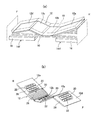
- FIG. 1 is a schematic perspective view of the bed apparatus by which the bottom which concerns on embodiment of this invention is mounted
- (b) is a perspective view of this bottom. It is a whole top view of a bottom. It is a top view of the back bottom of a bottom.
- (A) is a plan view of a required portion in which the bottom waist bottom, knee bottom, and foot bottom are integrated
- (b) is a sectional view taken along line BB in (a).
- 4A is a cross-sectional view taken along the line AA in FIG. 3
- FIG. 4B is a cross-sectional view of the foot side member taken along the line CC in FIG.
- FIG. 1A is an overall perspective view of a bed apparatus on which a bottom according to the present invention is mounted
- FIG. 1B is a perspective view of the bottom
- FIGS. 2 to 5 are explanatory views of the bottom.
- the head side facing the user's head lying on the bed apparatus is indicated by the symbol “H”
- the foot side facing the user's foot is indicated by the symbol “F”.
- the bed apparatus mainly includes an upper frame 10 having a generally ladder-like structure in which the length direction with the ends facing the head side and the foot side is longer than the width direction, and the upper frame 10 A bottom 12 placed on the head, and a head-side elevating part 14H, which is provided on the lower side of the head side and the foot side of the upper frame 10 and supports the upper frame 10 so as to be movable up and down on the floor surface;
- the foot side raising / lowering part 14F is provided.
- each of the elevating parts 14H and 14F is detachably connected by a connecting frame. Further, each of the elevating parts 14H and 14F is provided with an actuator, and the driving force of each actuator is controlled separately, and the upper frame 10 is moved to the vertical position between the head side and the foot side by the driving control of each actuator. A tilting motion with a difference can be performed.
- the upper frame is provided with a rod for raising the back on the head side and a rod for raising the knee near the center.
- An actuator for driving them is also provided.
- the bottom 12 supports a user's load with a mattress (generally indicated by reference numeral “18” in FIG. 1) placed thereon.
- the bottom 12 includes plate-like portions of a back bottom 12a for supporting the head and back of the user, a waist bottom 12b for supporting the waist, a knee bottom 12c for supporting from the waist to the knee, and a foot bottom 12d for supporting the foot beyond the knee. .
- the bottom 12 provided on the upper portion thereof can be raised and lowered. That is, the back bottom 12a of the bottom 12 can be lifted up with the back lifting rod, and the knee bottom 12c and the foot bottom 12d can be lifted up and lifted with the knee lifting rod. Yes.
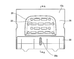
- the bottom 12 includes a back plate 12a, a waist bottom 12b, a knee bottom 12c, and a foot bottom 12d, each of which is made of a thick resin plate.
- a recess 20 is recessed on the upper surface of each part. It is formed with.
- a plurality of through holes 22 extending from the bottom 12 surface to the back surface are formed in the recess 20 formation place.
- the plurality of through holes 22 are arranged in the width direction and the length direction of the bottom 12.
- the shape and number of the through-holes 22 are appropriate, but in the embodiment, as shown in FIG. 2, the through-holes 22 have a plurality of circular and oval shapes in the width direction (the major axis is along the width direction). Are arranged in a plurality in the length direction of the bottom 12.
- the bottom 12 is formed with a recess 20 in the upper surface, and the recess 20 is formed in the center of the bottom 12 in the width direction.
- a recess 20 is formed to be recessed in a region continuous with the back bottom 12a, the waist bottom 12b, the knee bottom 12c, and the foot bottom 12d.
- the recess 20 is formed in the surface of the bottom 12 leaving the periphery of the bottom 12 entirely.
- a concave portion is left leaving a flat edge 26 at the head side end of the back bottom 12a, both sides of the back bottom 12a, the waist bottom 12b, the knee bottom 12c and the foot bottom 12d, and the foot side end of the foot bottom 12d. 20 is formed. That is, the recess 20 is formed on the inner side surrounded by the flat edge portion 26 and can be formed with an appropriate size in the width direction of the bottom. / 2 to 4/5 etc. is appropriate.
- the recess 20 has a back bottom 12a of the bottom 12, a waist bottom 12b, a knee bottom 12c, an edge 26 of each part of the foot bottom 12d, and the like. It is formed with a depth of 1/2 or less of the thick part.
- the periphery connected from the edge 26 of the recess 20 is gently chamfered at an angle of about 30 ° to 50 ° with respect to the flat surface to prevent a user from feeling a butt. ing.
- the recess 20 is formed at the center in the width direction of the bottom 12, the portion that the body touches when the user sleeps on the bed apparatus is compared with the flat part. Alleviated. At the same time, the air permeability of the bottom can be ensured by the through hole 22, so that the feeling when the user lies down becomes good. Further, the mattress 18 on the bottom 12 is also stuck in the recess 20 and is not easily displaced with respect to the bottom 12, and the displacement can be prevented.
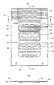
- each part of the bottom 12 as shown in FIG. 3, the back bottom 12a of each part is a single member.
- the waist bottom 12b, the knee bottom 12c, and the foot bottom 12d of each part are required parts, and they are connected by a connecting part 24, and the whole is configured as a single member.
- the connecting portion 24 is made of the same material as the required portion and is integrally formed thinner than the required portion.
- the curved bottom 28 is slidably contacted with the back bottom 12a and connected to the waist bottom 12b of the required portion so as to be bent.
- the curved bottom 28 has a trapezoidal cross-sectional shape of elongated bar-like portions along the width direction of the bottom 12 and a plurality of rod-like portions arranged in the length direction of the bottom 12, and each rod-like portion is connected by a thin portion. It is a structure that can be folded into a slatted or bellows shape.
- the curved bottom 28 fits in the connecting recess 30 of the back bottom 12a so as to be slidably contacted and bent in the length direction of the bottom 12, and a pin body (not shown) is slidably fitted into the long hole 30a of the back bottom 12a. Wait, they are connected to each other.
- FIG. 5A shows an enlarged cross section of the back bottom 12a
- FIG. 5B shows a cross sectional view of the waist bottom 12b, the knee bottom 12c, and the foot bottom 12d.
- the scales are different, but in the bottom recess 20, the recess 20 of the waist bottom 12b is formed deepest as shown in FIG. 5 (b) (depth d1).
- the recess of the knee bottom 12c is deeply formed (depth d2).
- the recess 20 (depth d3) of the back bottom 12a and the recess 20 (depth d4) of the foot bottom 12d are formed shallower than the recess 20 of the knee bottom 12c.
- the depth of the recess 20 has a relationship of d1> d2> d3 (ord4).
- the waist portion 12b is held in a state where the waist bottom 12b is slightly recessed, and the waist portion is depressed by the user's recess when raising the back or the legs. Since it does not move so much, it is possible to reliably prevent the user's back from bending.
- the bottom of the bed apparatus of the present invention can be used as the bottom of various bed apparatuses such as a home care bed apparatus, a facility care bed apparatus, and a hospital bed apparatus.
Abstract
Description
ボトムは、厚みのある樹脂製の板材からなる、背ボトム、腰ボトム、膝ボトム、及び足ボトムの各部を有してなり、
それら各部のうちの所要部同士が連結部によって連結構成され、該連結部が前記所要部と同材質でかつ所要部よりも薄く一体に形成されたものであり、
前記ボトムには、ボトム上面に凹所が形成され、その凹所はボトムの幅方向中央部に形成され、該凹所形成箇所には、ボトム表面から裏面にかけての貫通孔が複数形成されていることを特徴とするベッド装置のボトムである。 The present invention is provided at the bottom of the bed apparatus and can be raised and lowered,
The bottom is made of a thick resin plate, and has a back bottom, a waist bottom, a knee bottom, and a foot bottom.
The required parts of these parts are connected to each other by a connecting part, and the connecting part is made of the same material as the required part and is integrally formed thinner than the required part.
The bottom is formed with a recess on the top surface of the bottom, and the recess is formed at the center in the width direction of the bottom, and a plurality of through-holes from the bottom surface to the back surface are formed at the recess formation portion. It is the bottom of the bed apparatus characterized by this.
また、凹所がボトムの幅方向中央部に形成されているので、使用者がベッド装置上に寝たときに体の当たる部分が平坦に比べて緩和される。それと共に貫通孔でボトムの通気性を確保できる。
したがって、使用者が寝た感触を良好にさせ得るという優れた効果を奏し得る。 According to the bottom of the bed apparatus of the present invention, the bottom has a back bottom, a waist bottom, a knee bottom, and a foot bottom, each of which is made of a thick resin plate material. The parts are connected to each other by a connecting part, and the connecting part is made of the same material as the required part and is integrally formed thinner than the required part, and sinks at the connecting part of each part for the user sleeping on the bed. Because it is not included, there is no feeling of unevenness between the mattresses.
In addition, since the recess is formed in the central portion in the width direction of the bottom, the portion that comes into contact with the body when the user lies on the bed apparatus is relaxed compared to the flat portion. At the same time, the air permeability of the bottom can be secured by the through hole.
Therefore, it is possible to achieve an excellent effect that the user can have a good feeling of sleeping.
12 ボトム
12a 背ボトム
12b 腰ボトム
12c 膝ボトム
12d 足ボトム
20 凹所
22 貫通孔
24 連結部
26 縁部
28 湾曲ボトム DESCRIPTION OF
Claims (4)
- ベッド装置の上部に設けられて起伏可能なボトムにおいて、
ボトムは、厚みのある樹脂製の板材からなる、背ボトム、腰ボトム、膝ボトム、及び足ボトムの各部を有してなり、
それら各部のうちの所要部同士が連結部によって連結構成され、該連結部が前記所要部と同材質でかつ所要部よりも薄く一体に形成されたものであり、
前記ボトムには、ボトム上面に凹所が形成され、その凹所はボトムの幅方向中央部に形成され、該凹所形成箇所には、ボトム表面から裏面にかけての貫通孔が複数形成されていることを特徴とするベッド装置のボトム。 In the bottom that can be undulated provided on the top of the bed device,
The bottom is made of a thick resin plate, and has a back bottom, a waist bottom, a knee bottom, and a foot bottom.
The required parts of these parts are connected to each other by a connecting part, and the connecting part is made of the same material as the required part and is integrally formed thinner than the required part.
The bottom is formed with a recess on the top surface of the bottom, and the recess is formed at the center in the width direction of the bottom, and a plurality of through-holes from the bottom surface to the back surface are formed at the recess formation portion. The bottom of the bed device characterized by that. - 前記ボトムの凹所は、ボトム全体の頭側部、足側部、及び幅方向両端部の周縁を残して、使用者の体側の幅に対応する寸法に形成されていることを特徴とする請求項1に記載のベッド装置のボトム。 The bottom recess is formed to have a dimension corresponding to the width of the user's body side, leaving the periphery of the head side portion, the foot side portion, and both ends in the width direction of the entire bottom. Item 2. The bottom of the bed apparatus according to Item 1.
- 前記ボトムの凹所は、腰ボトムが最も深く形成され、次に膝ボトムが深く形成されていることを特徴とする請求項1または2に記載のベッド装置のボトム。 The bottom of the bed apparatus according to claim 1 or 2, wherein the bottom recess is formed such that a waist bottom is formed deepest and then a knee bottom is formed deeply.
- 前記ボトムは、所要部が腰ボトム、膝ボトム、足ボトムであって、腰ボトムに湾曲部が延在し、該湾曲部が背ボトムに重なって、背上げ作動時に前記湾曲部が背ボトムに摺接しかつ折り曲げ可能に連結する構成であることを特徴とする請求項1から3のうちの1項に記載のベッド装置のボトム。 The bottom includes a waist bottom, a knee bottom, and a foot bottom, and a curved portion extends to the waist bottom, and the curved portion overlaps the back bottom, so that the curved portion becomes a back bottom during back raising operation. The bottom of the bed apparatus according to any one of claims 1 to 3, wherein the bottom of the bed apparatus is connected to be slidable and bendable.
Priority Applications (7)
| Application Number | Priority Date | Filing Date | Title |
|---|---|---|---|
| KR1020157031528A KR20160002877A (en) | 2013-04-19 | 2014-03-19 | Bottom for bed device |
| EP14785015.0A EP2987476A4 (en) | 2013-04-19 | 2014-03-19 | Bottom for bed device |
| JP2015512367A JP6145504B2 (en) | 2013-04-19 | 2014-03-19 | Bed equipment bottom and bed equipment |
| US14/782,375 US9635949B2 (en) | 2013-04-19 | 2014-03-19 | Bottom for bed apparatus |
| CN201480022250.3A CN105142591A (en) | 2013-04-19 | 2014-03-19 | Bottom for bed device |
| SG11201507697PA SG11201507697PA (en) | 2013-04-19 | 2014-03-19 | Bottom for bed apparatus |
| US15/467,599 US9814323B2 (en) | 2013-04-19 | 2017-03-23 | Bottom for bed apparatus |
Applications Claiming Priority (2)
| Application Number | Priority Date | Filing Date | Title |
|---|---|---|---|
| JP2013088383 | 2013-04-19 | ||
| JP2013-088383 | 2013-04-19 |
Related Child Applications (2)
| Application Number | Title | Priority Date | Filing Date |
|---|---|---|---|
| US14/782,375 A-371-Of-International US9635949B2 (en) | 2013-04-19 | 2014-03-19 | Bottom for bed apparatus |
| US15/467,599 Continuation US9814323B2 (en) | 2013-04-19 | 2017-03-23 | Bottom for bed apparatus |
Publications (1)
| Publication Number | Publication Date |
|---|---|
| WO2014171254A1 true WO2014171254A1 (en) | 2014-10-23 |
Family
ID=51731211
Family Applications (1)
| Application Number | Title | Priority Date | Filing Date |
|---|---|---|---|
| PCT/JP2014/057586 WO2014171254A1 (en) | 2013-04-19 | 2014-03-19 | Bottom for bed device |
Country Status (8)
| Country | Link |
|---|---|
| US (2) | US9635949B2 (en) |
| EP (1) | EP2987476A4 (en) |
| JP (1) | JP6145504B2 (en) |
| KR (1) | KR20160002877A (en) |
| CN (1) | CN105142591A (en) |
| SG (2) | SG11201507697PA (en) |
| TW (1) | TWI620536B (en) |
| WO (1) | WO2014171254A1 (en) |
Families Citing this family (9)
| Publication number | Priority date | Publication date | Assignee | Title |
|---|---|---|---|---|
| US20160037936A1 (en) * | 2013-04-18 | 2016-02-11 | Paramount Bed Co., Ltd. | Bottom for bed apparatus |
| TR201902844T4 (en) * | 2014-10-14 | 2019-03-21 | Malvestio S P A | Bed for hospitalization. |
| US10506884B2 (en) * | 2016-02-24 | 2019-12-17 | Dreamwell, Ltd. | Adjustable foundation |
| US10639221B2 (en) * | 2016-02-24 | 2020-05-05 | Dreamwell, Ltd. | Adjustable foundation and mattress assembly |
| US10568434B2 (en) * | 2016-02-24 | 2020-02-25 | Dreamwell, Ltd. | Adjustable foundation |
| JP6997631B2 (en) * | 2018-01-11 | 2022-01-17 | パラマウントベッド株式会社 | Bottom member, bottom, and bed device |
| USD889864S1 (en) * | 2018-05-14 | 2020-07-14 | Bombardier Inc. | Lounge chair |
| US11554062B2 (en) | 2018-10-08 | 2023-01-17 | Stryker Corporation | Patient support apparatus having patient support deck and gap covering deck section |
| KR102441656B1 (en) * | 2022-02-15 | 2022-09-07 | 강용원 | High-strength patient bed with press-steel plate structure |
Citations (4)
| Publication number | Priority date | Publication date | Assignee | Title |
|---|---|---|---|---|
| EP0558108A2 (en) * | 1992-01-30 | 1993-09-01 | Schell Industries B.V. | Universally adjustable bed |
| JP2005509450A (en) * | 2001-03-27 | 2005-04-14 | ヒル−ロム サービシーズ,インコーポレイティド | Hospital bed |
| JP2006198352A (en) | 2005-01-24 | 2006-08-03 | Paramount Bed Co Ltd | Bed apparatus having mattress slip preventing function |
| WO2011161930A1 (en) * | 2010-06-21 | 2011-12-29 | パナソニック株式会社 | Wheelchair and bed |
Family Cites Families (8)
| Publication number | Priority date | Publication date | Assignee | Title |
|---|---|---|---|---|
| JPH04352908A (en) * | 1991-05-29 | 1992-12-08 | Matsushita Electric Ind Co Ltd | Integrally formed structure for bed or the like |
| EP0641534B1 (en) * | 1993-09-08 | 1998-12-16 | Paramount Bed Company Limited | A bed base structure |
| GB2362566B (en) | 2000-05-27 | 2002-07-17 | Huntleigh Technology Plc | Adjustable platform |
| US6389622B1 (en) * | 2000-08-03 | 2002-05-21 | Chiou-Feng Her | Hospital bed |
| JP2002102294A (en) * | 2000-10-04 | 2002-04-09 | Nishikawa Kasei Co Ltd | Reinforcing structure of bed board |
| GB0514926D0 (en) * | 2005-07-20 | 2005-08-24 | Huntleigh Technology Plc | Bed assembly |
| JP5243995B2 (en) | 2009-02-24 | 2013-07-24 | パナソニック株式会社 | Electric bed |
| US20160037936A1 (en) * | 2013-04-18 | 2016-02-11 | Paramount Bed Co., Ltd. | Bottom for bed apparatus |
-
2014
- 2014-03-19 SG SG11201507697PA patent/SG11201507697PA/en unknown
- 2014-03-19 WO PCT/JP2014/057586 patent/WO2014171254A1/en active Application Filing
- 2014-03-19 EP EP14785015.0A patent/EP2987476A4/en not_active Withdrawn
- 2014-03-19 SG SG10201708408RA patent/SG10201708408RA/en unknown
- 2014-03-19 JP JP2015512367A patent/JP6145504B2/en active Active
- 2014-03-19 KR KR1020157031528A patent/KR20160002877A/en not_active Application Discontinuation
- 2014-03-19 CN CN201480022250.3A patent/CN105142591A/en active Pending
- 2014-03-19 US US14/782,375 patent/US9635949B2/en active Active
- 2014-04-09 TW TW103112997A patent/TWI620536B/en not_active IP Right Cessation
-
2017
- 2017-03-23 US US15/467,599 patent/US9814323B2/en active Active
Patent Citations (4)
| Publication number | Priority date | Publication date | Assignee | Title |
|---|---|---|---|---|
| EP0558108A2 (en) * | 1992-01-30 | 1993-09-01 | Schell Industries B.V. | Universally adjustable bed |
| JP2005509450A (en) * | 2001-03-27 | 2005-04-14 | ヒル−ロム サービシーズ,インコーポレイティド | Hospital bed |
| JP2006198352A (en) | 2005-01-24 | 2006-08-03 | Paramount Bed Co Ltd | Bed apparatus having mattress slip preventing function |
| WO2011161930A1 (en) * | 2010-06-21 | 2011-12-29 | パナソニック株式会社 | Wheelchair and bed |
Non-Patent Citations (1)
| Title |
|---|
| See also references of EP2987476A4 * |
Also Published As
| Publication number | Publication date |
|---|---|
| EP2987476A1 (en) | 2016-02-24 |
| US9814323B2 (en) | 2017-11-14 |
| TWI620536B (en) | 2018-04-11 |
| TW201507666A (en) | 2015-03-01 |
| KR20160002877A (en) | 2016-01-08 |
| US9635949B2 (en) | 2017-05-02 |
| SG11201507697PA (en) | 2015-11-27 |
| JP6145504B2 (en) | 2017-06-14 |
| US20170188717A1 (en) | 2017-07-06 |
| CN105142591A (en) | 2015-12-09 |
| EP2987476A4 (en) | 2016-11-16 |
| SG10201708408RA (en) | 2017-11-29 |
| JPWO2014171254A1 (en) | 2017-02-23 |
| US20160029807A1 (en) | 2016-02-04 |
Similar Documents
| Publication | Publication Date | Title |
|---|---|---|
| WO2014171254A1 (en) | Bottom for bed device | |
| JP6422859B2 (en) | Bed equipment bottom | |
| JP6278983B2 (en) | Bed equipment | |
| KR101680870B1 (en) | Medical bed | |
| JP6411845B2 (en) | Floor bed mattress | |
| JP6581459B2 (en) | Bed equipment | |
| JP6193607B2 (en) | Bed equipment | |
| JP2017225759A (en) | Leg bottom support structure and bed apparatus | |
| JP3835701B2 (en) | Mattress and bed | |
| JP6337371B2 (en) | Electric bed | |
| JP6681684B2 (en) | Sleeper device | |
| JP7165801B2 (en) | bed component and bed device | |
| JP6704306B2 (en) | Body support device | |
| JP6909684B2 (en) | Mattress cover structure and mattress | |
| JP2019198746A (en) | Bed device | |
| KR102640268B1 (en) | Foundation insertion type electric bed | |
| JP2014226368A (en) | Foot bottom support mechanism in bed device | |
| CN107019605B (en) | Bed | |
| JP2005349016A (en) | Draining-board-like bottom of lying-on-the-back board of bed or the like | |
| JP6242073B2 (en) | Bed unit bottom fixing structure | |
| JP2010194180A (en) | Bed device |
Legal Events
| Date | Code | Title | Description |
|---|---|---|---|
| WWE | Wipo information: entry into national phase |
Ref document number: 201480022250.3 Country of ref document: CN |
|
| 121 | Ep: the epo has been informed by wipo that ep was designated in this application |
Ref document number: 14785015 Country of ref document: EP Kind code of ref document: A1 |
|
| WWE | Wipo information: entry into national phase |
Ref document number: 14782375 Country of ref document: US |
|
| ENP | Entry into the national phase |
Ref document number: 2015512367 Country of ref document: JP Kind code of ref document: A |
|
| WWE | Wipo information: entry into national phase |
Ref document number: 2014785015 Country of ref document: EP |
|
| NENP | Non-entry into the national phase |
Ref country code: DE |
|
| ENP | Entry into the national phase |
Ref document number: 20157031528 Country of ref document: KR Kind code of ref document: A |
|
| WWE | Wipo information: entry into national phase |
Ref document number: IDP00201507395 Country of ref document: ID |