WO2014171001A1 - 符号化方法及び符号化装置 - Google Patents
符号化方法及び符号化装置 Download PDFInfo
- Publication number
- WO2014171001A1 WO2014171001A1 PCT/JP2013/061566 JP2013061566W WO2014171001A1 WO 2014171001 A1 WO2014171001 A1 WO 2014171001A1 JP 2013061566 W JP2013061566 W JP 2013061566W WO 2014171001 A1 WO2014171001 A1 WO 2014171001A1
- Authority
- WO
- WIPO (PCT)
- Prior art keywords
- bit depth
- state
- unit
- encoding
- image information
- Prior art date
- Legal status (The legal status is an assumption and is not a legal conclusion. Google has not performed a legal analysis and makes no representation as to the accuracy of the status listed.)
- Ceased
Links
Images





Classifications
-
- H—ELECTRICITY
- H04—ELECTRIC COMMUNICATION TECHNIQUE
- H04N—PICTORIAL COMMUNICATION, e.g. TELEVISION
- H04N19/00—Methods or arrangements for coding, decoding, compressing or decompressing digital video signals
- H04N19/10—Methods or arrangements for coding, decoding, compressing or decompressing digital video signals using adaptive coding
- H04N19/169—Methods or arrangements for coding, decoding, compressing or decompressing digital video signals using adaptive coding characterised by the coding unit, i.e. the structural portion or semantic portion of the video signal being the object or the subject of the adaptive coding
- H04N19/184—Methods or arrangements for coding, decoding, compressing or decompressing digital video signals using adaptive coding characterised by the coding unit, i.e. the structural portion or semantic portion of the video signal being the object or the subject of the adaptive coding the unit being bits, e.g. of the compressed video stream
-
- H—ELECTRICITY
- H04—ELECTRIC COMMUNICATION TECHNIQUE
- H04N—PICTORIAL COMMUNICATION, e.g. TELEVISION
- H04N19/00—Methods or arrangements for coding, decoding, compressing or decompressing digital video signals
- H04N19/10—Methods or arrangements for coding, decoding, compressing or decompressing digital video signals using adaptive coding
- H04N19/102—Methods or arrangements for coding, decoding, compressing or decompressing digital video signals using adaptive coding characterised by the element, parameter or selection affected or controlled by the adaptive coding
-
- H—ELECTRICITY
- H04—ELECTRIC COMMUNICATION TECHNIQUE
- H04N—PICTORIAL COMMUNICATION, e.g. TELEVISION
- H04N19/00—Methods or arrangements for coding, decoding, compressing or decompressing digital video signals
- H04N19/10—Methods or arrangements for coding, decoding, compressing or decompressing digital video signals using adaptive coding
- H04N19/134—Methods or arrangements for coding, decoding, compressing or decompressing digital video signals using adaptive coding characterised by the element, parameter or criterion affecting or controlling the adaptive coding
- H04N19/136—Incoming video signal characteristics or properties
- H04N19/14—Coding unit complexity, e.g. amount of activity or edge presence estimation
-
- H—ELECTRICITY
- H04—ELECTRIC COMMUNICATION TECHNIQUE
- H04N—PICTORIAL COMMUNICATION, e.g. TELEVISION
- H04N19/00—Methods or arrangements for coding, decoding, compressing or decompressing digital video signals
- H04N19/10—Methods or arrangements for coding, decoding, compressing or decompressing digital video signals using adaptive coding
- H04N19/134—Methods or arrangements for coding, decoding, compressing or decompressing digital video signals using adaptive coding characterised by the element, parameter or criterion affecting or controlling the adaptive coding
- H04N19/146—Data rate or code amount at the encoder output
- H04N19/15—Data rate or code amount at the encoder output by monitoring actual compressed data size at the memory before deciding storage at the transmission buffer
-
- H—ELECTRICITY
- H04—ELECTRIC COMMUNICATION TECHNIQUE
- H04N—PICTORIAL COMMUNICATION, e.g. TELEVISION
- H04N19/00—Methods or arrangements for coding, decoding, compressing or decompressing digital video signals
- H04N19/10—Methods or arrangements for coding, decoding, compressing or decompressing digital video signals using adaptive coding
- H04N19/169—Methods or arrangements for coding, decoding, compressing or decompressing digital video signals using adaptive coding characterised by the coding unit, i.e. the structural portion or semantic portion of the video signal being the object or the subject of the adaptive coding
- H04N19/17—Methods or arrangements for coding, decoding, compressing or decompressing digital video signals using adaptive coding characterised by the coding unit, i.e. the structural portion or semantic portion of the video signal being the object or the subject of the adaptive coding the unit being an image region, e.g. an object
- H04N19/172—Methods or arrangements for coding, decoding, compressing or decompressing digital video signals using adaptive coding characterised by the coding unit, i.e. the structural portion or semantic portion of the video signal being the object or the subject of the adaptive coding the unit being an image region, e.g. an object the region being a picture, frame or field
-
- H—ELECTRICITY
- H04—ELECTRIC COMMUNICATION TECHNIQUE
- H04N—PICTORIAL COMMUNICATION, e.g. TELEVISION
- H04N19/00—Methods or arrangements for coding, decoding, compressing or decompressing digital video signals
- H04N19/10—Methods or arrangements for coding, decoding, compressing or decompressing digital video signals using adaptive coding
- H04N19/169—Methods or arrangements for coding, decoding, compressing or decompressing digital video signals using adaptive coding characterised by the coding unit, i.e. the structural portion or semantic portion of the video signal being the object or the subject of the adaptive coding
- H04N19/17—Methods or arrangements for coding, decoding, compressing or decompressing digital video signals using adaptive coding characterised by the coding unit, i.e. the structural portion or semantic portion of the video signal being the object or the subject of the adaptive coding the unit being an image region, e.g. an object
- H04N19/176—Methods or arrangements for coding, decoding, compressing or decompressing digital video signals using adaptive coding characterised by the coding unit, i.e. the structural portion or semantic portion of the video signal being the object or the subject of the adaptive coding the unit being an image region, e.g. an object the region being a block, e.g. a macroblock
-
- H—ELECTRICITY
- H04—ELECTRIC COMMUNICATION TECHNIQUE
- H04N—PICTORIAL COMMUNICATION, e.g. TELEVISION
- H04N7/00—Television systems
- H04N7/18—Closed-circuit television [CCTV] systems, i.e. systems in which the video signal is not broadcast
Definitions
- the technical field relates to video coding.
- Patent Document 1 "Providing an encoding technique for efficiently encoding moving images with different pixel depths” (Patent Document 1 [0006]) is an issue, and as a means for solving them, “Moving images” Are hierarchically encoded, among a plurality of bit planes that give image data, an upper bit plane group is assigned to a basic layer, and a bit plane group having a larger number of bits including the upper bit plane group is assigned to an enhancement layer, In the enhancement layer, the difference between the difference picture by prediction in the enhancement layer and the difference picture by prediction in the base layer is encoded to generate encoded data of the enhancement layer ”(Patent Document 1 [0007] Reference).
- Patent Document 1 does not consider reduction of power consumption.
- the present application includes a plurality of means for solving the above-described problems.
- a step of inputting image information and a feature of the input image information are described.
- An analysis step for analyzing, a bit depth output step for determining and outputting a bit depth for video encoding, and an encoding step for encoding image information input using the bit depth output in the bit depth output step The bit depth output step switches the bit depth to be output based on the analysis result of the analysis step.
- the power consumption can be reduced by changing the bit depth according to the characteristics of the image and the remaining power.
- An example of a video encoding device in the first embodiment An example showing the feature amount of the image and the feature amount threshold range in the first embodiment Another example showing the feature amount of the image and the feature amount threshold range in the first embodiment An example showing the feature amount of the image and the feature amount threshold range in the first embodiment An example showing a feature value threshold range and a range threshold in the first embodiment Example showing bit depth for each frame in the first embodiment Another example showing bit depth for each frame in the first embodiment Another example showing bit depth for each frame in the first embodiment An example of a video encoding device in the second embodiment An example of a system using the video encoding device in the first embodiment or the second embodiment It is an example of a vehicle-mounted camera system. It is an example of a surveillance camera system. It is an example of a video conference system.
- H. is a typical video encoding method.
- a profile is defined according to the bit depth, and high gradation can be realized by video coding at a high bit depth.
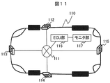
- FIG. 11 is a block diagram showing an example of an in-vehicle camera system.
- a network 111 is mounted in the car 110, and camera units 112, 113, 114, 115, and an ECU (Engine Control Unit) unit 116 are connected to the network 111.
- a monitor unit 117 is connected to the ECU unit.
- the camera units 112, 113, 114, and 115 send image information around the imaged car 110 to the network 111.
- the video information may be sent to the network 111 without being compressed, or may be sent to the network 111 after being subjected to pressure processing by the camera units 112, 113, 114, and 115.
- the ECU unit 116 receives the video information sent to the network 111 and outputs the video information to the monitor 117. If the input video information is compressed, the ECU unit 116 performs decompression processing and outputs the obtained decoded video information to the monitor 117.
- the monitor unit 117 performs video display of input video information.
- the ECU unit 116 and the camera units 112, 113, 114, and 115 can exchange control signals via the network 111.
- the ECU unit 116 can instruct the camera units 112, 113, 114, and 115 with information necessary for camera processing and compression processing.
- information necessary for camera processing includes shooting start and shooting stop.
- Some information necessary for the compression process includes a bit depth and a control threshold value.
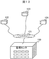
- FIG. 12 is a block diagram showing an example of a monitoring system. This example is an example of a monitoring system in which camera units 122, 123, and 124 and a monitoring center 120 are connected to a network 121.
- the camera units 122, 123, and 124 capture image information of surroundings where the respective camera units are installed, and send them to the network 121.
- the video information may be sent to the network 121 without being compressed, or may be sent to the network 121 after being subjected to pressure processing by the camera units 122, 123, and 124.
- the monitoring center 120 inputs the video information sent to the network 121 and analyzes the video information. If the input video information is compressed, the monitoring center 120 performs an expansion process.
- the monitoring center may have a monitor that displays the video information.
- the monitoring center 120 and the camera units 122, 123, and 124 can exchange control signals via the network 111.
- the monitoring center 120 can instruct the camera units 122, 123, and 124 with information necessary for camera processing and compression processing.
- information necessary for camera processing includes shooting start and shooting stop.
- Some information necessary for the compression process includes a bit depth and a control threshold value.
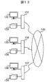
- FIG. 13 is a block diagram showing an example of a video conference system. This example is an example of a TV conference system in which the terminal units 131, 134, and 137 are connected to the network 130.
- the terminal unit 131 includes a camera unit 133 and a monitor unit 132.
- the camera unit 133 captures video information around the camera unit and outputs it to the terminal unit 131.
- the terminal unit 131 sends the input video information to the network 130.
- the video information may be sent to the network 130 without being compressed, or may be sent to the network 130 after being subjected to pressure processing by the camera unit 133 or the terminal unit 131. Further, the terminal unit 131 inputs video information sent to the network 130 and outputs it to the monitor unit 132.
- the monitor unit 132 displays the input video information. If the input video information is compressed, the terminal unit 131 or the monitor unit 132 decompresses the video information, and displays the decoded video information on the monitor unit.
- the terminal units 131, 134, and 137 can exchange control signals with each terminal unit via the network 130.
- the terminal unit 131 can instruct the terminal unit 134 of information necessary for camera processing and compression processing.
- information necessary for camera processing includes shooting start and shooting stop.
- Some information necessary for the compression process includes a bit depth and a control threshold value.
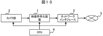
- FIG. 10 is a block diagram illustrating an example of a camera system.
- Each block may be configured by hardware, or a part or all of the function of each block may be realized using software.
- the camera unit 2 is a block that digitizes and outputs the captured image.
- the video encoding device 1 is a block that encodes and outputs image information output from the camera unit 2.
- the network interface 3 is a block that outputs video encoded data output from the video encoding device 1 to a network 5 such as a LAN.
- the CPU 4 is a block that controls the camera unit 2, the video encoding device 1, and the network interface 3.
- an image captured by the camera unit 2 is encoded by the video encoding device 1 and then output to the network 5 via the network interface 3.
- FIG. 1 is a block diagram illustrating an example of a video encoding apparatus according to the present embodiment.
- Each block may be configured by hardware, or a part or all of the function of each block may be realized using software.
- the video encoding device 1 is a video encoding device that performs input image encoding processing and outputs encoded video data.
- the video encoding device 1 is used in, for example, a broadcast video distribution system, a broadcast relay system, a mobile terminal, a surveillance camera system, an in-vehicle camera system, and the like.
- the input unit 10 is a block for inputting image data to the video encoding device.
- Examples of image data input to the input unit include image data captured by an external camera and image data recorded on an external recording medium.
- the input image analysis unit 11 receives the image data captured by the input unit 10 and extracts the feature amount of one or more types of image data for each feature amount extraction region.
- the feature amount extraction region there is a rectangular pixel block including one pixel and X pixels ⁇ Y pixels (X and Y are both positive numbers).
- the rectangular pixel block there is a macroblock composed of 16 pixels ⁇ 16 pixels which is a unit of video encoding.
- Examples of the feature amount of the image data include a luminance value, a color difference value, a luminance or color difference variance value, a luminance or color difference average value, and a luminance or color difference correlation value.
- An example of the average value is an average value of luminance values in a macroblock.
- the bit depth determination unit 12 receives the feature amount of the image data, the feature amount threshold value 100, and the range threshold value 101, and determines and outputs the bit depth.
- the bit depth determination unit 12 extracts a feature amount extraction region where the feature amount of the image data is greater than or equal to the feature amount threshold value 100. If the region where the extracted feature amount extraction regions are equal to or greater than the range threshold value 101, the bit depth determination unit 12 Output a higher bit depth than.
- the feature amount threshold value 100 and the range threshold value 101 are supplied from, for example, the CPU 4 in FIG. Note that the bit depth determination unit 12 is also referred to as a bit depth output unit.
- An example of the unit of the range threshold 101 is a pixel.
- the range threshold 101 is 4096 pixels
- a higher bit depth is output when the extracted continuous feature amount extraction region is 4096 pixels or more than when it is less than 4096 pixels.
- Another example of the unit of the range threshold 101 is a feature amount extraction area.
- the feature quantity extraction region is a macroblock composed of 16 pixels ⁇ 16 pixels.
- the range threshold 101 is 16 macroblocks
- a higher bit depth is output when the extracted continuous feature amount extraction area is 16 macroblocks or more than when it is less than 16 macroblocks.
- bit depth there are 8 bits, 10 bits, and 12 bits.
- the bit depth determination unit 12 outputs 12 bits when the continuous region of the feature amount extraction region is the range threshold 101 or more, In this case, 8 bits are output.
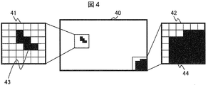
- FIG. 4 is a diagram illustrating an example when the unit of the range threshold 101 is a feature amount extraction region.
- the feature amount threshold value 100 has a lower limit value B0 and the range threshold value 101 has an upper limit value A1.
- a frame 40 indicates an image frame region to be encoded.
- the feature amount extraction region of the black portion is a feature amount extraction region in which the feature amount of the image data is less than the lower limit value B0.
- the image areas 41 and 42 are enlarged views with respect to a partial image area in the frame 40 configured by a 6 ⁇ 6 feature amount extraction area.
- Each feature amount extraction region is configured by a macroblock of 16 pixels ⁇ 16 pixels.
- the image areas 43 and 44 shown in black are feature quantity extraction areas in which the feature quantity of the image data is less than the lower limit value B0.
- the number of extracted feature quantity extraction regions in the image region 41 is five regions.
- the number of extracted feature amount extraction regions in the image region 42 is 23 regions.
- the bit depth for the frame 40 is The bit depth higher than the bit depth for the frame constituted only by the image regions having the number of consecutive feature quantity extraction regions less than the upper limit value A1 is output.
- the upper limit value A1 of the range threshold 101 When the upper limit value A1 of the range threshold 101 is set to 10, one of the five extracted feature quantity extraction regions in the frame 40 and the 23 regions is equal to or greater than the upper limit value A1, so the bit for the frame 40 As the depth, a bit depth higher than the bit depth for a frame composed of only image regions in which the number of extracted feature amount extraction regions is less than the upper limit value A1 is output.
- the upper limit value A1 of the range threshold 101 is set to 100, the number of consecutive feature quantity extraction regions extracted in the frame 40 is less than the upper limit value A1, so that the bit depth for the frame 40 is continuously extracted.
- a bit depth lower than the bit depth for a frame including an image area whose feature quantity extraction area is equal to or greater than the upper limit A1 is output.
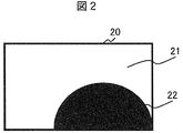
- FIG. 2 is an example of an image captured by the in-vehicle camera.
- a lower limit value B0 is provided as the feature amount threshold value 100
- an upper limit value A1 is provided as the range threshold value 101
- a feature amount extraction region in which the feature amount of the image data is less than the lower limit value B0 is illustrated in black.
- a region 22 in the frame 20 indicates a feature amount extraction region where the feature amount of the image data is less than the lower limit value B0.
- the other region 21 indicates a feature amount extraction region where the feature amount of the image data is equal to or greater than the lower limit value B0.
- the bit depth determination unit 12 outputs a lower bit depth than when the region 22 is N or more during the period until the region 22 becomes N.
- the bit depth determination unit 12 switches the bit depth to be output, and outputs a higher bit depth than when the region 22 is less than N.
- the bit depth determination unit 12 switches the bit depth to be output, and outputs a higher bit depth than when the region 22 is less than N.
- the car is away from the tunnel, it will need to approach the tunnel to a certain distance, output a lower bit depth than when entering the tunnel, approach the tunnel, and look inside the tunnel in detail.
- the load of the encoding process can be reduced on average.
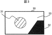
- FIG. 3 is an example of an image captured by the in-vehicle camera.
- an upper limit value A0 and a lower limit value B0 are provided as the feature amount threshold value
- an upper limit value A1 is provided as the range threshold value 101
- a feature amount extraction region in which the feature amount of the image data is less than the lower limit value B0 is shown in black.
- a feature amount extraction area whose feature amount is equal to or greater than the upper limit value A0 is indicated by hatching.
- the area 32 indicates an area in which the feature amount of the image data is less than the lower limit value B0.
- An area 31 indicates an area where the feature amount of the image data is equal to or greater than the upper limit value A0.
- a region 33 indicates a region where the feature amount of the image data is not less than the lower limit value B0 and less than the upper limit value A0.
- a high bit depth is output.
- the area 31 is a high brightness area and the area 32 is a low brightness area.
- FIG. 5 shows an example in which image frames are arranged in time order.
- a lower limit value B0 is provided as the feature amount threshold value 100
- an upper limit value A1 is provided as the range threshold value 101.
- Frames 50, 51, 52, 53, 54, and 55 indicate image frames arranged in time order.
- the black portion in each frame indicates a region where the feature amount of the image data is less than the lower limit value B0 and a region where the number of consecutive extracted feature amount extraction regions is the upper limit value A1 or more.
- the frames 50 and 51 include a region where the feature amount of the image data is less than the lower limit value B0 and a region where the number of extracted feature amount extraction regions is equal to or greater than the upper limit value A1.
- bit depth A is lower than the bit depth B
- bit depth B a region where the feature amount of the image data is less than the lower limit A0 and a region where the number of extracted feature amount extraction regions is the upper limit value A1 or more.
- Bit depth B is output when the signal exists, and bit depth A is output otherwise.
- bit depth B is output for the frames 50 and 51
- bit depth A is output for the frames 52, 53, 54, and 55.
- FIG. 6 shows another example in which image frames are arranged in time order.
- the feature amount threshold 100 includes a lower limit value B0
- the range threshold 101 includes an upper limit value A1 and dead zone information C1.
- Dead zone information is information for maintaining the conventional bit depth without changing the bit depth for the designated number of frames when the bit depth changes.
- the unit of the dead zone information C1 is the number of frames, and the value of the dead zone information C1 is 2 in FIG.
- Frames 60, 61, 62, 63, 64, and 65 indicate image frames arranged in time order.
- the black portion in each frame indicates a region where the feature amount of the image data is less than the lower limit value B0 and a region where the number of consecutive extracted feature amount extraction regions is the upper limit value A1 or more.
- the frames 60 and 61 include a region where the feature amount of the image data is less than the lower limit value B0 and a region where the number of extracted feature amount extraction regions is equal to or greater than the upper limit value A1.
- bit depth A is lower than the bit depth B as in FIG. 5, the number of extracted feature amount extraction regions that are regions where the feature amount of the image data is less than the lower limit value A0 is greater than or equal to the upper limit value A1.
- a bit depth B is output for frames 60 and 61 in which an area is present.
- Dead zone information for frames 62, 63, 64, and 65 in which there is no region where the feature amount of the image data is less than the lower limit value A0 and the number of consecutive extracted feature amount extraction regions is the upper limit value A1 or more.
- the bit depth B that is the immediately preceding bit depth is maintained.
- the bit depth A is output for the number of frames indicated by the dead band information C1, that is, the frames after two frames, that is, the frames 64 and 65.
- the process shown in FIG. 6 can avoid frequent bit depth switching and erroneous bit depth switching.
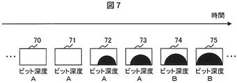
- FIG. 7 shows another example in which image frames are arranged in time order.
- the feature amount threshold value 100 has a lower limit value B0
- the range threshold value 101 has an upper limit value A1 and dead zone information D1.
- the unit of the dead zone information D1 is the number of frames.
- the value of the dead zone information D1 is set to 2.
- Frames 70, 71, 72, 73, 74, and 75 indicate image frames arranged in time order.
- the black portion in each frame indicates a region where the feature amount of the image data is less than the lower limit value B0 and a region where the number of extracted feature amount extraction regions is equal to or greater than the upper limit value A1.
- the frames 70 and 71 there is no area where the feature amount of the image data is less than the lower limit value B0 and the number of consecutive extracted feature amount extraction areas is the upper limit value A1 or more.
- the frames 72, 73, 74, and 75 there are regions where the feature amount of the image data is less than the lower limit value B0 and the number of extracted feature amount extraction regions that are continuously extracted is the upper limit value A1 or more.
- bit depth A is lower than the bit depth B as in FIG. 5, the number of extracted feature amount extraction regions that are regions where the feature amount of the image data is less than the lower limit value A0 is greater than or equal to the upper limit value A1.
- a bit depth A is output for frames 70 and 71 in which no region exists.
- Dead zone information is provided for frames 72, 73, 74, and 75 in which there are regions where the feature amount of the image data is less than the lower limit value A0 and the number of consecutive extracted feature amount extraction regions is the upper limit value A1 or more.
- D1 the number of frames indicated by D1 that is, two frames, that is, the frames 72 and 73
- the bit depth A that is the immediately preceding bit depth is maintained.
- a high bit depth A is output for the number of frames indicated by the dead zone information D1, that is, the frames after two frames, that is, the frames 74 and 75.
- the processing shown in FIG. 7 can avoid frequent bit depth switching and erroneous switching.
- FIG. 8 shows another example in which image frames are arranged in time order.
- the feature amount threshold value 100 has a lower limit value B0
- the range threshold value 101 has an upper limit value A1 and high bit depth insertion interval information E1.
- the high bit depth insertion interval information is information indicating a frame interval at which a high bit depth B is inserted.
- the unit of the high bit depth insertion interval information E1 is the number of frames. In FIG. 8, the value of the high bit depth insertion interval E1 is 2.
- Frames 80, 81, 82, 83, 84, and 85 indicate image frames arranged in time order.
- the black portion in each frame indicates a region where the feature amount of the image data is less than the lower limit value B0 and a region where the number of consecutive extracted feature amount extraction regions is the upper limit value A1 or more.
- the frames 82, 83, 84, and 85 there are regions where the feature amount of the image data is less than the lower limit value B0, and regions where the number of consecutive feature amount extraction regions is equal to or more than the upper limit value A1.
- a high bit depth B is output for each frame interval indicated by the high bit depth insertion interval E1, and a low bit depth is output for other frames.
- the processing shown in FIG. 8 can avoid frequent bit depth switching and erroneous switching.
- the bit depth depends on whether or not there is a region where the feature amount of the image data is less than the lower limit value B0 and the number of consecutive extracted feature amount extraction regions is the upper limit value A1 or more.
- the bit depth switching may be controlled by another method based on the feature amount of the image data. For example, when the area or ratio of a region whose feature amount is less than a predetermined lower limit (for example, the ratio occupied in one frame) is greater than or equal to a predetermined threshold, the bit depth is higher than when the area is less than the predetermined value. Is output.
- FIG. 9 is a block diagram showing another example of the video encoding device.
- Each block may be configured by hardware, or a part or all of the function of each block may be realized using software.
- the video encoding device in FIG. 9 is configured to be input to the external environment information 900 bit depth determination unit 90 in addition to the video encoding device shown in FIG.
- the external environment information 900 is supplied from, for example, the CPU 4 in FIG. 10, similarly to the feature amount threshold value 100 and the range threshold value 101.
- the bit depth determination unit 90 is also referred to as a bit depth output unit.
- the remaining power level of the battery connected to the video encoding device as the external environment information 900 and the power level threshold value as the feature amount threshold 100, for example, the remaining power level of the battery connected to the video encoding device. Is less than the power threshold value, a lower bit depth is output than in other cases. As a result, when the remaining amount of power of the battery to which the present video encoding device is connected is reduced, it is possible to save power in the video encoding device.
Landscapes
- Engineering & Computer Science (AREA)
- Multimedia (AREA)
- Signal Processing (AREA)
- Compression Or Coding Systems Of Tv Signals (AREA)
Abstract
Description
本願は上記課題を解決する手段を複数含んでいるが、その一例を挙げるならば、画像情報を符号化する符号化方法において、画像情報が入力されるステップと、入力された画像情報の特徴を解析する解析ステップと、 映像符号化に対するビット深度を決定して出力するビット深度出力ステップと、ビット深度出力ステップで出力したビット深度を用いて入力された画像情報の符号化処理を行う符号化ステップと、を有し、ビット深度出力ステップでは、解析ステップの解析結果に基づいて出力するビット深度を切替えることを特徴とする。
10 入力部
11 入力画像解析部
12 ビット深度判定部
13 映像符号化部
100 特徴量閾値
101 範囲閾値
Claims (14)
- 画像情報が入力されるステップと、
入力された画像情報の特徴を解析する解析ステップと、
映像符号化に対するビット深度を決定して出力するビット深度出力ステップと、
前記ビット深度出力ステップで出力したビット深度を用いて入力された画像情報の符号化処理を行う符号化ステップと、を有し、
前記ビット深度出力ステップでは、前記解析ステップの解析結果に基づいて出力するビット深度を切替えることを特徴とする符号化方法。 - 請求項1の符号化方法であって、
前記ビット深度出力ステップでは、前記解析ステップで解析された特徴の量が所定の閾値内である領域が第1の状態から第2の状態に変化すると、出力するビット深度を第1のビット深度から第2のビット深度に切り替えることを特徴とする符号化方法。 - 請求項2の符号化方法であって、
前記解析ステップでは、入力された画像情報の特徴量を所定の単位領域ごとに解析し、
前記第1の状態とは前記解析ステップで解析された特徴量が所定の閾値内である単位領域の連続する数が所定の数以上である状態であり、
前記第2の状態とは前記解析ステップで解析された特徴量が所定の閾値内である単位領域の連続する数が前記所定の数未満である状態であり、
前記第1のビット深度は前記第2のビット深度よりも高いことを特徴とする符号化方法。 - 請求項2の符号化方法であって、
前記第1の状態とは前記解析ステップで解析された特徴の量が所定の閾値内である領域の広さが所定の広さ以上である状態であり、
前記第2の状態とは前記解析ステップで解析された特徴の量が所定の閾値内である領域の広さが前記所定の広さ未満である状態であり、
前記第1のビット深度は前記第2のビット深度よりも高いことを特徴とする符号化方法。 - 請求項2の符号化方法であって、
前記第1の状態とは前記解析ステップで解析された特徴の量が所定の閾値内である領域の1フレームに占める割合が所定の割合以上である状態であり、
前記第2の状態とは前記解析ステップで解析された特徴の量が所定の閾値内である領域の1フレームに占める割合が前記所定の割合未満である状態であり、
前記第1のビット深度は前記第2のビット深度よりも高いことを特徴とする符号化方法。 - 請求項2~5の符号化方法であって、
前記ビット深度出力ステップにおいて、前記解析ステップで解析された特徴の量が所定の閾値内である領域が前記第1の状態から前記第2の状態に変化しても、変化してから所定の時間が経過するまでビット深度の切り替えを行わないことを特徴とする符号化方法。 - 画像情報が入力される入力部と、
前記入力部に入力された画像情報の特徴を解析する解析部と、
映像符号化に対するビット深度を決定して出力するビット深度出力部と、
前記ビット深度出力部から出力されたビット深度を用いて前記入力部に入力された画像情報の符号化処理を行う符号化部と、を有し、
前記ビット深度出力部では、前記解析部の解析結果に基づいて出力するビット深度を切替えることを特徴とする符号化装置。 - 請求項7の符号化装置であって、
前記ビット深度出力部では、前記解析部で解析された特徴の量が所定の閾値内である領域が第1の状態から第2の状態に変化すると、出力するビット深度を第1のビット深度から第2のビット深度に切り替えることを特徴とする符号化装置。 - 請求項8の符号化装置であって、
前記解析部では、入力された画像情報の特徴量を所定の単位領域ごとに解析し、
前記第1の状態とは前記解析部で解析された特徴量が所定の閾値内である単位領域の連続する数が所定の数以上である状態であり、
前記第2の状態とは前記解析部で解析された特徴量が所定の閾値内である単位領域の連続する数が前記所定の数未満である状態であり、
前記第1のビット深度は前記第2のビット深度よりも高いことを特徴とする符号化装置。 - 請求項8の符号化装置であって、
前記第1の状態とは前記解析部で解析された特徴の量が所定の閾値内である領域の広さが所定の広さ以上である状態であり、
前記第2の状態とは前記解析部で解析された特徴の量が所定の閾値内である領域の広さが前記所定の広さ未満である状態であり、
前記第1のビット深度は前記第2のビット深度よりも高いことを特徴とする符号化装置。 - 請求項8の符号化装置であって、
前記第1の状態とは前記解析部で解析された特徴の量が所定の閾値内である領域の1フレームに占める割合が所定の割合以上である状態であり、
前記第2の状態とは前記解析部で解析された特徴の量が所定の閾値内である領域の1フレームに占める割合が前記所定の割合未満である状態であり、
前記第1のビット深度は前記第2のビット深度よりも高いことを特徴とする符号化装置。 - 請求項8~11の符号化装置であって、
前記ビット深度出力部は、前記解析部で解析された特徴の量が所定の閾値内である領域が前記第1の状態から前記第2の状態に変化しても、変化してから所定の時間が経過するまでビット深度の切り替えを行わないことを特徴とする符号化装置。 - 画像情報が入力される入力部と、
前記入力部に入力された画像情報の符号化処理を行う符号化部と、を有し、
前記入力部に第1の特徴量を有する画像情報が入力されると、前記符号化部は第1のビット深度で符号化処理を行い、
前記入力部に第1の特徴量とは異なる第2の特徴量を有する画像情報が入力されると、前記符号化部は前記第1のビット深度とは異なる第2のビット深度で符号化処理を行うことを特徴とする符号化装置。 - 請求項13の符号化装置であって、
前記第1の特徴量を有する画像情報とは、当該画像情報の特徴量が所定の閾値未満の画像情報であり、
前記第2の特徴量を有する画像情報とは、当該画像情報の特徴量が所定の閾値以上の画像情報であり、
前記第1のビット深度は前記第2のビット深度よりも高いことを特徴とする符号化装置。
Priority Applications (4)
| Application Number | Priority Date | Filing Date | Title |
|---|---|---|---|
| PCT/JP2013/061566 WO2014171001A1 (ja) | 2013-04-19 | 2013-04-19 | 符号化方法及び符号化装置 |
| US14/784,796 US10554986B2 (en) | 2013-04-19 | 2013-04-19 | Encoding method and encoding device |
| CN201380075235.0A CN105284116B (zh) | 2013-04-19 | 2013-04-19 | 摄像方法和摄像装置 |
| JP2015512260A JP6093009B2 (ja) | 2013-04-19 | 2013-04-19 | 符号化方法及び符号化装置 |
Applications Claiming Priority (1)
| Application Number | Priority Date | Filing Date | Title |
|---|---|---|---|
| PCT/JP2013/061566 WO2014171001A1 (ja) | 2013-04-19 | 2013-04-19 | 符号化方法及び符号化装置 |
Publications (1)
| Publication Number | Publication Date |
|---|---|
| WO2014171001A1 true WO2014171001A1 (ja) | 2014-10-23 |
Family
ID=51730970
Family Applications (1)
| Application Number | Title | Priority Date | Filing Date |
|---|---|---|---|
| PCT/JP2013/061566 Ceased WO2014171001A1 (ja) | 2013-04-19 | 2013-04-19 | 符号化方法及び符号化装置 |
Country Status (4)
| Country | Link |
|---|---|
| US (1) | US10554986B2 (ja) |
| JP (1) | JP6093009B2 (ja) |
| CN (1) | CN105284116B (ja) |
| WO (1) | WO2014171001A1 (ja) |
Families Citing this family (1)
| Publication number | Priority date | Publication date | Assignee | Title |
|---|---|---|---|---|
| CN113875232B (zh) * | 2019-05-16 | 2024-07-09 | 北京字节跳动网络技术有限公司 | 视频编解码中的自适应颜色格式转换 |
Citations (2)
| Publication number | Priority date | Publication date | Assignee | Title |
|---|---|---|---|---|
| JPH07131655A (ja) * | 1993-11-02 | 1995-05-19 | Fujitsu Commun Syst Ltd | 動的多値化データ圧縮装置 |
| JP2003169284A (ja) * | 2001-12-04 | 2003-06-13 | Fuji Photo Film Co Ltd | 画像変換装置並びに画像変換プログラム |
Family Cites Families (14)
| Publication number | Priority date | Publication date | Assignee | Title |
|---|---|---|---|---|
| JP3409421B2 (ja) | 1994-04-05 | 2003-05-26 | 松下電器産業株式会社 | 高能率符号化装置 |
| JP3926947B2 (ja) | 1999-06-22 | 2007-06-06 | 富士フイルム株式会社 | 画像データ形成装置および画像データ処理方法 |
| JP2005354170A (ja) | 2004-06-08 | 2005-12-22 | Fuji Photo Film Co Ltd | 撮像装置 |
| JP2007266749A (ja) | 2006-03-27 | 2007-10-11 | Sanyo Electric Co Ltd | 符号化方法 |
| US8208560B2 (en) * | 2007-10-15 | 2012-06-26 | Intel Corporation | Bit depth enhancement for scalable video coding |
| US8346203B2 (en) * | 2009-08-14 | 2013-01-01 | Apple Inc. | Power management techniques for buffering and playback of audio broadcast data |
| JP5583439B2 (ja) * | 2010-03-17 | 2014-09-03 | パナソニック株式会社 | 画像符号化装置及びカメラシステム |
| US9024951B2 (en) * | 2011-02-16 | 2015-05-05 | Apple Inc. | Devices and methods for obtaining high-local-contrast image data |
| JP5791336B2 (ja) * | 2011-04-01 | 2015-10-07 | キヤノン株式会社 | 画像処理装置及びその制御方法 |
| US9363522B2 (en) * | 2011-04-28 | 2016-06-07 | Warner Bros. Entertainment, Inc. | Region-of-interest encoding enhancements for variable-bitrate mezzanine compression |
| JPWO2013032008A1 (ja) * | 2011-09-02 | 2015-03-23 | 株式会社ニコン | 画像処理装置、プログラム |
| KR102013240B1 (ko) * | 2012-02-02 | 2019-08-22 | 삼성전자주식회사 | 영역별 특성에 기초한 영상 부호화 방법 및 그 장치, 그리고 영상 복호화 방법 및 그 장치 |
| US9432694B2 (en) * | 2012-03-06 | 2016-08-30 | Apple Inc. | Signal shaping techniques for video data that is susceptible to banding artifacts |
| US10182241B2 (en) * | 2014-03-04 | 2019-01-15 | Microsoft Technology Licensing, Llc | Encoding strategies for adaptive switching of color spaces, color sampling rates and/or bit depths |
-
2013
- 2013-04-19 US US14/784,796 patent/US10554986B2/en active Active
- 2013-04-19 CN CN201380075235.0A patent/CN105284116B/zh active Active
- 2013-04-19 JP JP2015512260A patent/JP6093009B2/ja active Active
- 2013-04-19 WO PCT/JP2013/061566 patent/WO2014171001A1/ja not_active Ceased
Patent Citations (2)
| Publication number | Priority date | Publication date | Assignee | Title |
|---|---|---|---|---|
| JPH07131655A (ja) * | 1993-11-02 | 1995-05-19 | Fujitsu Commun Syst Ltd | 動的多値化データ圧縮装置 |
| JP2003169284A (ja) * | 2001-12-04 | 2003-06-13 | Fuji Photo Film Co Ltd | 画像変換装置並びに画像変換プログラム |
Also Published As
| Publication number | Publication date |
|---|---|
| CN105284116A (zh) | 2016-01-27 |
| CN105284116B (zh) | 2019-05-21 |
| JPWO2014171001A1 (ja) | 2017-02-16 |
| US20160080750A1 (en) | 2016-03-17 |
| US10554986B2 (en) | 2020-02-04 |
| JP6093009B2 (ja) | 2017-03-08 |
Similar Documents
| Publication | Publication Date | Title |
|---|---|---|
| TWI804478B (zh) | 編碼包括隱私遮罩之影像之方法 | |
| CN105472205B (zh) | 编码过程中的实时视频降噪方法和装置 | |
| EP3402204B1 (en) | Encoding a video stream having a privacy mask | |
| US11095899B2 (en) | Image processing apparatus, image processing method, and storage medium | |
| JP2018137730A (ja) | プライバシーマスクされた画像を符号化すること | |
| CN112543330B (zh) | 模糊隐私遮蔽的编码方法、系统及存储介质 | |
| CN101350929A (zh) | 表示图像帧的非帧边缘区块时的增强的压缩 | |
| US20150139500A1 (en) | Method and System for Optimizing Image Processing in Driver Assistance Systems | |
| JP6093009B2 (ja) | 符号化方法及び符号化装置 | |
| CN113785582A (zh) | 从原影像流生成有用影像流的程序、装置以及方法 | |
| US10049436B1 (en) | Adaptive denoising for real-time video on mobile devices | |
| JP6499686B2 (ja) | 符号化方法及び符号化装置 | |
| JP2010268307A (ja) | 動画像処理装置、動画像処理プログラム、及び動画像処理方法 | |
| US20200106821A1 (en) | Video processing apparatus, video conference system, and video processing method | |
| CN112911299A (zh) | 一种视频码率控制方法、装置、电子设备和存储介质 | |
| JP2021013145A (ja) | 動画像伝送装置、動画像伝送方法 | |
| KR100487374B1 (ko) | 디지털 비디오의 썸네일 영상 생성 장치 | |
| EP4492773A1 (en) | Video data processing technology for reducing transmission bandwidth | |
| CN118678082B (zh) | 一种图像编解码方法、装置、编码器、解码器和系统 | |
| JP2021013148A (ja) | 動画像伝送装置、動画像伝送方法 | |
| JP2005122571A (ja) | 画像処理装置、画像処理方法、プログラム及び記憶媒体 | |
| JP4241918B2 (ja) | 動画像圧縮装置 | |
| CN121967696A (zh) | 图像编码方法、图像解码方法、装置、设备、存储介质及程序产品 | |
| CN119277081A (zh) | 一种图像的感兴趣区域确定方法及相关装置 | |
| Zhang et al. | VLSI architecture of a low complexity face detection algorithm for real-time video encoding |
Legal Events
| Date | Code | Title | Description |
|---|---|---|---|
| WWE | Wipo information: entry into national phase |
Ref document number: 201380075235.0 Country of ref document: CN |
|
| 121 | Ep: the epo has been informed by wipo that ep was designated in this application |
Ref document number: 13882095 Country of ref document: EP Kind code of ref document: A1 |
|
| WWE | Wipo information: entry into national phase |
Ref document number: 14784796 Country of ref document: US |
|
| ENP | Entry into the national phase |
Ref document number: 2015512260 Country of ref document: JP Kind code of ref document: A |
|
| NENP | Non-entry into the national phase |
Ref country code: DE |
|
| 122 | Ep: pct application non-entry in european phase |
Ref document number: 13882095 Country of ref document: EP Kind code of ref document: A1 |