WO2014167764A1 - Fuel cell system - Google Patents

Fuel cell system Download PDF

Info

Publication number
WO2014167764A1
WO2014167764A1 PCT/JP2014/000877 JP2014000877W WO2014167764A1 WO 2014167764 A1 WO2014167764 A1 WO 2014167764A1 JP 2014000877 W JP2014000877 W JP 2014000877W WO 2014167764 A1 WO2014167764 A1 WO 2014167764A1
Authority
WO
WIPO (PCT)
Prior art keywords
exhaust gas
cathode
fuel cell
supplied
air
Prior art date
Application number
PCT/JP2014/000877
Other languages
French (fr)
Japanese (ja)
Inventor
尾沼 重徳
鵜飼 邦弘
剛広 丸山
Original Assignee
パナソニック株式会社
Priority date (The priority date is an assumption and is not a legal conclusion. Google has not performed a legal analysis and makes no representation as to the accuracy of the date listed.)
Filing date
Publication date
Application filed by パナソニック株式会社 filed Critical パナソニック株式会社
Priority to EP14782374.4A priority Critical patent/EP2985830B1/en
Priority to US14/407,462 priority patent/US9515329B2/en
Priority to JP2014546233A priority patent/JP5870320B2/en
Publication of WO2014167764A1 publication Critical patent/WO2014167764A1/en

Links

Images

Classifications

    • HELECTRICITY
    • H01ELECTRIC ELEMENTS
    • H01MPROCESSES OR MEANS, e.g. BATTERIES, FOR THE DIRECT CONVERSION OF CHEMICAL ENERGY INTO ELECTRICAL ENERGY
    • H01M8/00Fuel cells; Manufacture thereof
    • H01M8/04Auxiliary arrangements, e.g. for control of pressure or for circulation of fluids
    • H01M8/04007Auxiliary arrangements, e.g. for control of pressure or for circulation of fluids related to heat exchange
    • H01M8/04014Heat exchange using gaseous fluids; Heat exchange by combustion of reactants
    • HELECTRICITY
    • H01ELECTRIC ELEMENTS
    • H01MPROCESSES OR MEANS, e.g. BATTERIES, FOR THE DIRECT CONVERSION OF CHEMICAL ENERGY INTO ELECTRICAL ENERGY
    • H01M8/00Fuel cells; Manufacture thereof
    • H01M8/04Auxiliary arrangements, e.g. for control of pressure or for circulation of fluids
    • H01M8/04007Auxiliary arrangements, e.g. for control of pressure or for circulation of fluids related to heat exchange
    • H01M8/04067Heat exchange or temperature measuring elements, thermal insulation, e.g. heat pipes, heat pumps, fins
    • H01M8/04074Heat exchange unit structures specially adapted for fuel cell
    • HELECTRICITY
    • H01ELECTRIC ELEMENTS
    • H01MPROCESSES OR MEANS, e.g. BATTERIES, FOR THE DIRECT CONVERSION OF CHEMICAL ENERGY INTO ELECTRICAL ENERGY
    • H01M8/00Fuel cells; Manufacture thereof
    • H01M8/06Combination of fuel cells with means for production of reactants or for treatment of residues
    • H01M8/0606Combination of fuel cells with means for production of reactants or for treatment of residues with means for production of gaseous reactants
    • H01M8/0612Combination of fuel cells with means for production of reactants or for treatment of residues with means for production of gaseous reactants from carbon-containing material
    • H01M8/0618Reforming processes, e.g. autothermal, partial oxidation or steam reforming
    • HELECTRICITY
    • H01ELECTRIC ELEMENTS
    • H01MPROCESSES OR MEANS, e.g. BATTERIES, FOR THE DIRECT CONVERSION OF CHEMICAL ENERGY INTO ELECTRICAL ENERGY
    • H01M8/00Fuel cells; Manufacture thereof
    • H01M8/06Combination of fuel cells with means for production of reactants or for treatment of residues
    • H01M8/0662Treatment of gaseous reactants or gaseous residues, e.g. cleaning
    • H01M8/0675Removal of sulfur
    • YGENERAL TAGGING OF NEW TECHNOLOGICAL DEVELOPMENTS; GENERAL TAGGING OF CROSS-SECTIONAL TECHNOLOGIES SPANNING OVER SEVERAL SECTIONS OF THE IPC; TECHNICAL SUBJECTS COVERED BY FORMER USPC CROSS-REFERENCE ART COLLECTIONS [XRACs] AND DIGESTS
    • Y02TECHNOLOGIES OR APPLICATIONS FOR MITIGATION OR ADAPTATION AGAINST CLIMATE CHANGE
    • Y02EREDUCTION OF GREENHOUSE GAS [GHG] EMISSIONS, RELATED TO ENERGY GENERATION, TRANSMISSION OR DISTRIBUTION
    • Y02E60/00Enabling technologies; Technologies with a potential or indirect contribution to GHG emissions mitigation
    • Y02E60/30Hydrogen technology
    • Y02E60/50Fuel cells

Definitions

  • the present invention relates to a fuel cell system including a desulfurization unit for desulfurizing a sulfur component from a raw material of an organic compound containing at least a sulfur component.
  • the present invention relates to a fuel cell system including a desulfurization unit that desulfurizes a sulfur component from a raw material by a hydrodesulfurization method.
  • the fuel cell system is supplied with an organic compound containing carbon and hydrogen components as raw materials.
  • the fuel cell system reforms the supplied raw material, for example, inside the fuel cell to generate hydrogen.
  • a reformer is provided outside the fuel cell, and a reformed gas containing hydrogen is generated by reforming the raw material by the reformer.
  • hydrogen is generated in this way, the fuel cell generates electricity and heat by a power generation reaction using the hydrogen and air supplied from the outside.
  • the fuel cell system configured as described above is expected as an effective energy supply system for reducing carbon dioxide, which is a cause of global warming, because it can efficiently obtain electric energy and thermal energy.
  • liquefied petroleum gas LPG
  • liquefied natural gas LNG
  • city gas shale gas
  • methane hydrate and the like
  • a odorant is added to such a raw material
  • the sulfur component is contained in the raw material itself or the odorant added to the raw material.
  • the sulfur component poisons the anode, leading to deterioration of the fuel cell performance or in the reformer.
  • the reforming catalyst contained is poisoned and the reforming performance is deteriorated. Therefore, it is necessary to supply the raw material to the anode and the reformer after reducing the sulfur component in the raw material to the ppb order.
  • a desulfurization section having a function of reducing sulfur components in the raw material is provided on the upstream side of the reformer.
  • a normal temperature desulfurization method in which the sulfur component is physically adsorbed and removed at a normal temperature or a hydrodesulfurization method in which the sulfur component is removed by using hydrogen, etc.
  • a catalyst having an activation temperature range of a predetermined temperature for example, about 250 ° C. to 320 ° C.
  • hydrogen sulfide is produced
  • the desulfurization section needs to be heated to maintain a predetermined temperature (for example, about 250 ° C. to 320 ° C. in the case of the hydrodesulfurization method) in order to stably remove the sulfur component.
  • a predetermined temperature for example, about 250 ° C. to 320 ° C. in the case of the hydrodesulfurization method
  • the fuel cell systems disclosed in Patent Documents 1 and 2 are disclosed as the fuel cell system that heats the desulfurization unit to a predetermined temperature.
  • Patent Document 1 proposes a fuel cell system that heats a desulfurization section as follows. That is, combustion exhaust gas (fuel cell exhaust gas) is generated by burning together the anode off gas discharged from the anode of the fuel cell and the cathode off gas discharged from the cathode. Then, heat exchange is performed between the combustion exhaust gas and the cathode air supplied to the cathode, and a part of the heated cathode air is supplied to the desulfurization unit as a heat source.
  • combustion exhaust gas fuel cell exhaust gas
  • Patent Document 2 in order to maintain the desulfurization part at a predetermined temperature, water (reformed water) supplied to the reformer as a reforming raw material takes heat from the burner and gives the deprived heat to the desulfurization catalyst.
  • a fuel cell system is presented.
  • the conventional fuel cell system has a problem that the desulfurization part cannot be heated to a temperature suitable for desulfurization.
  • Patent Document 1 discloses a desulfurization air supply line and a cathode air supply line in order to divert part of the cathode air supplied to the cathode and to heat a part of the cathode air by the combustion exhaust gas. And branch off.
  • Each supply line is provided with a flow control valve. In such a configuration, the flow rate of the cathode air supplied to the desulfurization unit is adjusted by controlling the flow rate control valve.
  • the flow rate control valves are provided and configured to control them.
  • the flow rate of the cathode air flowing through the desulfurization air supply line and the flow rate of the cathode air flowing through the cathode air supply line are as follows. There is a problem that it is difficult to control the flow rate so as to have an appropriate flow rate. For this reason, it becomes difficult to supply the heated cathode air at an appropriate flow rate to the desulfurization unit, and the temperature of the desulfurization unit may not be maintained at an appropriate temperature. Furthermore, since the fuel cell system of Patent Document 1 is separately provided with a flow control valve, there is a problem that the configuration becomes more complicated and costly.
  • the fuel cell system according to Patent Document 2 has a configuration in which water supplied to the reformer as a reforming raw material takes heat from the burner as described above and gives this deprived heat to the desulfurization catalyst. For this reason, it is suitable when the temperature of the desulfurization part is maintained near 100 ° C., but there is a problem that it cannot cope with a predetermined temperature (for example, about 250 ° C. to 320 ° C.) required for hydrodesulfurization.
  • a predetermined temperature for example, about 250 ° C. to 320 ° C.
  • the present invention has been made in view of the above-described problems, and an object of the present invention is to provide a fuel cell system capable of heating a desulfurization section so as to have an appropriate temperature for desulfurization.
  • a fuel cell system uses a fuel cell that generates power by a power generation reaction using fuel supplied to an anode and air supplied to a cathode, and is used in the fuel cell.
  • a cathode air heat exchanger that transfers a part of the thermal energy of the cathode exhaust gas to the air by exchanging heat between the cathode exhaust gas that is the air after being heated and the air supplied to the cathode;
  • a desulfurization section that removes the sulfur component of the supplied raw material, and a reformer that generates a reformed gas that serves as the fuel from the raw material from which the sulfur component has been removed by the desulfurization section and steam, and at least the cathode Cathode exhaust gas, in which part of the heat energy is lost due to heat exchange in the air heat exchanger, is supplied to the desulfurization section, and the heat energy of the cathode exhaust gas More heating the desulfurization unit.
  • the fuel cell system according to the present invention is configured as described above, and has an effect that the desulfurization section can be heated to a temperature suitable for desulfurization.
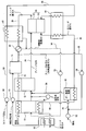
  • FIG. 1 is a block diagram illustrating an example of a fuel cell system according to Embodiment 1.
  • FIG. It is a figure which shows an example of a structure of the desulfurization part with which the fuel cell system shown in FIG. 1 is provided. It is a figure which shows an example of a structure of the desulfurization part with which the fuel cell system shown in FIG. 1 is provided.
  • 5 is a block diagram illustrating an example of a fuel cell system according to Embodiment 2.
  • FIG. 6 is a block diagram illustrating an example of a fuel cell system according to Embodiment 3.
  • FIG. 6 is a block diagram illustrating an example of a fuel cell system according to Embodiment 4.
  • the present invention provides the following aspects.
  • a fuel cell system includes a fuel cell that generates power by a power generation reaction using fuel supplied to an anode and air supplied to a cathode, and a fuel cell after being used in the fuel cell.
  • a cathode air heat exchanger that moves part of the thermal energy of the cathode exhaust gas to the air by exchanging heat between the cathode exhaust gas that is air and the air supplied to the cathode, and the supplied raw material
  • a desulfurization section that removes the sulfur component of the catalyst, and a reformer that generates a reformed gas that serves as the fuel from the raw material from which the sulfur component has been removed by the desulfurization section and steam, and at least the cathode air heat exchanger
  • the cathode exhaust gas, in which part of the heat energy has been lost due to heat exchange, is supplied to the desulfurization unit, and the desulfurization unit is added by the thermal energy of the cathode exhaust gas.
  • the cathode air heat exchanger since the cathode air heat exchanger is provided, the air supplied to the cathode is preheated, while the cathode exhaust gas discharged from the cathode is in a state where a part of the heat energy is lost. Then, at least part of the heat energy is removed by heat exchange in the cathode air heat exchanger, and the cathode exhaust gas whose temperature has been reduced is supplied to the desulfurization unit. Can be heated. That is, the cathode air heat exchanger can reduce the temperature of the cathode exhaust gas so that the desulfurization part can be heated at an appropriate temperature, and can supply the cathode exhaust gas adjusted to the appropriate temperature to the desulfurization part.
  • the fuel cell system of the present invention has an effect that the desulfurization part can be heated so that the temperature becomes appropriate for desulfurization.
  • the cathode exhaust gas supplied to the desulfurization part is one in which a part of heat energy is lost due to heat exchange in at least the cathode air heat exchanger. Therefore, the cathode exhaust gas may be supplied directly from the cathode air heat exchanger to the desulfurization unit. Alternatively, the cathode exhaust gas may be supplied to the desulfurization unit in a state where a part of the heat energy is further lost in the additional heat exchanger or the like via another additional heat exchanger or the like.
  • the fuel cell system according to a second aspect of the present invention is the fuel cell system according to the first aspect, wherein the fuel cell system uses the anode exhaust gas used as the fuel in the fuel cell and discharged from the anode, and the cathode.
  • An anode exhaust gas condenser that condenses the anode exhaust gas and collects condensed water by exchanging heat with air before being supplied and transferring a part of the thermal energy of the anode exhaust gas to the air.
  • a part of the heat of the anode exhaust gas is obtained by heat exchange in the anode exhaust gas condenser, and preheated air is supplied to the cathode air heat exchanger.
  • the anode exhaust gas condenser since the anode exhaust gas condenser is provided, the anode exhaust gas can be condensed and the condensed water can be recovered. For this reason, even in a place where the outside air temperature is high, condensed water can be recovered from the anode exhaust gas, and water can be independent even when the fuel cell system is operated. In addition, it is possible to prevent the anode exhaust gas from being condensed and generating water clogging in the course of the passage of the anode exhaust gas.
  • the air after the air is preheated by the anode exhaust gas condenser, it can be further supplied to the cathode air heat exchanger and further heated. For this reason, air can be supplied to the cathode in a properly preheated state.
  • the fuel cell system according to a third aspect of the present invention is the fuel cell system according to the second aspect, wherein the desulfurization section is configured to remove the sulfur component of the raw material by a hydrodesulfurization method. May be.
  • the fuel cell system according to a fourth aspect of the present invention is the fuel cell system according to the third aspect, wherein a part of the anode exhaust gas from which condensed water is recovered by the anode exhaust gas condenser is diverted to the desulfurization section.
  • the desulfurization section further includes a recycle path that is a path for supplying the upstream side of the gas, and the desulfurization unit adsorbs a sulfur component in the raw material in a mixed gas obtained by mixing a part of the anode exhaust gas and the raw material. You may be comprised so that it may have a catalyst.
  • the desulfurization part can adsorb
  • the fuel cell system according to a fifth aspect of the present invention is the fuel cell system according to any one of the second to fourth aspects, wherein the anode exhaust gas condenser is utilized by using the supplied combustion air.
  • the reformer further comprises a combustion section for combusting the anode exhaust gas from which condensed water has been collected by the combustion section, and the reformer utilizes the thermal energy of the combustion exhaust gas generated by burning the anode exhaust gas by the combustion section.
  • the reformed gas may be generated from the supplied raw material and water vapor by a quality reaction.
  • the reformer since the combustion section is provided, the reformer can be heated to a predetermined temperature using the thermal energy of the combustion exhaust gas generated by the combustion section. For this reason, a reformer can be made into the predetermined temperature required in order to implement reforming reaction, and reforming reaction can be implemented efficiently.
  • the fuel cell system according to a sixth aspect of the present invention is the fuel cell system according to the fifth aspect, wherein combustion exhaust gas in which a part of thermal energy is used in the reformer is supplied, and the combustion exhaust gas It may be configured to include an evaporating section that vaporizes the condensed water using the thermal energy possessed by and generates water vapor to be added to the raw material supplied to the reformer.
  • the combustion exhaust gas that is used by the reformer and loses part of the heat energy is supplied to the evaporation section, and the condensed water can be vaporized using the heat energy of the combustion exhaust gas.
  • the evaporation part can produce
  • the fuel cell system according to a seventh aspect of the present invention is the fuel cell system according to the fifth aspect, wherein the reformer heats the combustion exhaust gas in which a part of heat energy is used and the desulfurization part.
  • the reformer heats the combustion exhaust gas in which a part of heat energy is used and the desulfurization part.
  • cathode exhaust gas that uses a part of the thermal energy is supplied, and the condensed water is vaporized by the thermal energy of the combustion exhaust gas and the cathode exhaust gas, respectively, to the raw material supplied to the reformer You may be comprised so that the evaporation part which produces
  • the evaporation section uses the combustion exhaust gas that is used in the reformer and loses a part of the heat energy, and the cathode that is used in the desulfurization section and that loses a part of the heat energy.
  • Exhaust gas is supplied. For this reason, for example, even when the condensed water cannot be sufficiently vaporized only by the thermal energy of the combustion exhaust gas, the shortage of thermal energy necessary for vaporizing this condensed water can be compensated by the thermal energy of the cathode exhaust gas. it can.
  • the fuel cell system according to an eighth aspect of the present invention is the fuel cell system according to the fifth aspect, wherein the combustion exhaust gas in which a part of thermal energy is used in the reformer and the cathode air heat exchange are used.
  • the cathode exhaust gas in which part of the heat energy is lost due to heat exchange in the cooler is supplied, and the condensed water is vaporized by the thermal energy of each of the combustion exhaust gas and the cathode exhaust gas and supplied to the reformer
  • the evaporation section uses the combustion exhaust gas that is used in the reformer and loses a part of the heat energy, and the cathode that is used in the desulfurization section and that loses a part of the heat energy.
  • Exhaust gas is supplied. For this reason, for example, even when the condensed water cannot be sufficiently vaporized only by the thermal energy of the combustion exhaust gas, the shortage of thermal energy necessary for vaporizing this condensed water can be compensated by the thermal energy of the cathode exhaust gas. it can.
  • the cathode exhaust gas after the heat exchange with the cathode air heat exchanger can be further supplied to the desulfurization unit by using heat in the evaporation unit. That is, even if the cathode exhaust heat cannot be lowered to the optimum temperature for heating the desulfurization unit by heat exchange in the cathode air heat exchanger, it is further supplied to the desulfurization unit using heat in the evaporation unit. By doing so, the cathode exhaust gas at the optimum temperature can be supplied to the desulfurization section. For this reason, the desulfurization part can perform desulfurization appropriately.
  • the fuel cell system according to a ninth aspect of the present invention is the fuel cell system according to the seventh aspect, wherein the fuel is supplied to the cathode exhaust gas in which a part of thermal energy is used in the evaporation unit and to the combustion unit. It may be configured to include a heat exchanger that exchanges heat with the combustion air.
  • a fuel cell system according to a tenth aspect of the present invention is the fuel cell system according to the eighth aspect, wherein the desulfurization unit uses a part of the thermal energy and is supplied to the combustion unit. It may be configured to include a heat exchanger that exchanges heat with the combustion air.
  • FIG. 1 is a block diagram illustrating an example of a fuel cell system according to the first embodiment.
  • the fuel cell system according to Embodiment 1 includes an evaporation unit 10, a reformer 12, a combustion unit 14, an anode exhaust gas condenser 16, an anode exhaust gas radiator 18, a fuel cell 20, and cathode air heat exchange. And a desulfurization section 46 on which a desulfurization catalyst 47 is mounted.
  • the raw material is first supplied to the desulfurization unit 46.
  • the desulfurization unit 46 removes sulfur components from the raw material by, for example, hydrodesulfurization, and supplies the raw material after this desulfurization to the reformer 12.
  • the hydrogen necessary for hydrodesulfurization in the desulfurization section 46 is part of the anode exhaust gas that is diverted from the anode exhaust gas containing anode gas (reformed gas) that is not used in the fuel cell 20. It is comprised so that it may be obtained from.
  • the reformer 12 is supplied with steam obtained by vaporizing condensed water in the evaporation unit 10 and reforming air supplied from the outside.
  • the fuel cell system according to Embodiment 1 is configured to condense the anode exhaust gas and use the obtained condensed water as reformed water, as will be described in detail later.
  • the reformer 12 reforms the supplied raw material using the vaporized condensed water and reforming air.
  • the reformer 12 generates an anode gas (reformed gas) containing hydrogen as the fuel for the fuel cell 20 and supplies the anode gas to the anode 22 of the fuel cell 20.
  • cathode air air
  • the fuel cell 20 uses the cathode air supplied to the cathode 24 and the anode gas supplied to the anode 22.
  • Power is generated by the power generation reaction.
  • the electric power obtained by the power generation of the fuel cell 20 is supplied to an external load via a terminal (not shown).
  • a terminal not shown.
  • a device constituting a radio base station such as a mobile phone can be used.
  • it can be set as a general household use or a commercial distributed generation apparatus, or a combined heat and power supply apparatus.
  • the fuel cell 20 included in the fuel cell system according to Embodiment 1 will be described by taking a solid oxide fuel cell (SOFC) as an example.
  • SOFC solid oxide fuel cell
  • any fuel cell that discharges anode offgas containing hydrogen may be used.
  • the fuel cell 20 is not limited to this.
  • the produced water (water vapor) is contained in the anode off gas, and the produced water can be efficiently condensed from the anode off gas even at a place where the outside air temperature is high.
  • a fuel cell such as a molten carbonate fuel cell (MCFC) is advantageous.
  • Examples of the raw material supplied from the outside in the fuel cell system according to Embodiment 1 include, for example, a gas containing an organic compound such as LPG gas, propane gas, butane gas, or city gas mainly containing methane, kerosene, or alcohol. Can be used.
  • a gas containing an organic compound such as LPG gas, propane gas, butane gas, or city gas mainly containing methane, kerosene, or alcohol.
  • the reformer 12 provided in the fuel cell system according to Embodiment 1 uses an oxidative steam reforming reaction (hydrocarbon reforming reaction) using hydrocarbons contained in the raw material after desulfurization and oxygen contained in the reforming air.
  • oxidative Steam Reforming oxidative Steam Reforming
  • the reforming reaction performed in the reformer 12 is not limited to the oxidative steam reforming reaction, and may be a partial oxidation reforming reaction, an autothermal reforming reaction, or a steam reforming reaction. .
  • the reforming reaction is likely to proceed in terms of heat balance, and the reformer 12 can be made smaller than a configuration using steam reforming. Is advantageous.
  • a sulfur compound is contained in the raw material, it is easily converted to SO 2 and then converted to H 2 S, and poisoning of the electrode catalyst of the anode 22 in the fuel cell 20 can be reduced. But it is advantageous.
  • the reformer 12 provided in the fuel cell system according to Embodiment 1 has a configuration in which, for example, a reforming catalyst is filled in a casing.
  • a reforming catalyst for example, an alumina carrier impregnated with at least one of nickel, ruthenium, platinum, and rhodium can be used.
  • the reforming catalyst is not particularly limited, and for example, various catalysts that can advance the oxidative steam reforming reaction can be used.
  • the reformer 12 needs to be maintained at a predetermined temperature when the oxidative steam reforming reaction proceeds. In the first embodiment, the reformer 12 is heated to a predetermined temperature by the thermal energy of the combustion exhaust gas generated by burning the anode exhaust gas in the combustion unit 14.
  • a cathode air supply 50 is provided in the middle of the cathode air passage 38 through which the cathode air flows, and the flow rate of air supplied to the cathode 24 by the cathode air supply 50 is as follows. Adjusted. A raw material supply device 52 is provided in the middle of the raw material path 28 through which the raw material flows, and the raw material flow rate supplied to the anode 22 is adjusted by the raw material supply device 52.
  • the fuel cell 20 includes the anode 22 to which the anode gas reformed by the reformer 12 is supplied and the cathode 24 to which cathode air is supplied.
  • a plurality of fuel cell single cells that generate electricity by performing a power generation reaction between them are connected in series.
  • YSZ yttria-stabilized zirconia
  • ZrO 2 zirconia
  • Y yttrium oxide
  • Y 2 O 3 yttrium oxide
  • electrolyte or the like yte oxide
  • zirconia doped with ytterbium (Yb) or scandium (Sc), or a lanthanum gallate solid electrolyte can be used.
  • Yb ytterbium
  • Sc scandium
  • a power generation reaction is performed in a temperature range of about 600 ° C. to 1000 ° C., for example.
  • an electrode material of the anode 22 for example, a mixture of nickel and YSZ or the like is used.
  • the electrode material of the cathode 24 for example, an oxide containing lanthanum, strontium, manganese (La 0.8 Sr 0.2 MnO 3 ), an oxide containing lanthanum, strontium, cobalt, iron (La 0.6 Sr 0.4 Co 0.2). Fe 0.8 O 3 ) or the like is used.
  • the cell structure of the fuel cell 20 is, for example, a flat plate type, and is configured such that anode exhaust gas and cathode exhaust gas are separately discharged from the fuel cell 20.
  • the structure of the fuel cell 20 is not particularly limited to a flat plate type, and may be a cylindrical type or a cylindrical flat plate type as long as the anode exhaust gas and the cathode exhaust gas are separately discharged, for example. .
  • the flow paths of the fluid supplied to the fuel cell system having the above-described configuration are mainly paths through which cathode air and cathode exhaust gas flow (cathode air path 38, cathode exhaust gas path 40), raw material, anode gas, and anode.
  • the exhaust gas and the combustion exhaust gas can be broadly classified into paths (a raw material path 28, an anode gas path 26, an anode exhaust gas path 29, and a combustion exhaust gas path 42). Therefore, in the following, both routes will be described individually.
  • the cathode air is supplied to the anode exhaust gas condenser 16 through the cathode air path 38 by the cathode air supplier 50.
  • the cathode air supplied to the anode exhaust gas condenser 16 is heated (preheated) by heat exchange with the anode exhaust gas supplied to the anode exhaust gas condenser 16 via another path.
  • the cathode air is supplied to the cathode air heat exchanger 44 in such a preheated state.
  • the cathode air heat exchanger 44 is configured such that cathode air before being supplied to the cathode 24 of the fuel cell 20 and cathode exhaust gas after being discharged from the cathode 24 are supplied respectively. Heat exchange takes place at.
  • the cathode exhaust gas immediately after being discharged from the cathode 24 has a high temperature of about 850 ° C. For this reason, the cathode air is heated to about 650 ° C. by heat exchange with the cathode exhaust gas in the cathode air heat exchanger 44. Conversely, the cathode exhaust gas is supplied to the desulfurization section 46 through the cathode exhaust gas path 40 in a state where the temperature is lowered to, for example, about 350 ° C. to 380 ° C. The cathode exhaust gas dissipates heat while flowing through the cathode exhaust gas passage 40 and is supplied to the desulfurization section 46 in a state where the temperature is lowered to about 250 ° C. to 320 ° C., for example.
  • the cathode exhaust gas passage 40 is configured so that the cathode exhaust gas hardly dissipates heat, the flow rate of the cathode air and the cathode exhaust gas flowing through the cathode air heat exchanger 44 is changed, or both of them exchange heat.
  • the temperature of the cathode exhaust gas can be adjusted to about 250 ° C. to 320 ° C., for example, by increasing the possible section.
  • the cathode exhaust gas of about 250 ° C. to 320 ° C. is supplied to the desulfurization section 46, desulfurization is performed to a desired temperature in the hydrodesulfurization method using a part of the thermal energy of the cathode exhaust gas.
  • the part 46 can be heated.
  • the cathode exhaust gas that has lost part of the heat energy by heating the desulfurization unit 46 is supplied to the evaporation unit 10. And in the evaporation part 10, a part of thermal energy which cathode exhaust gas has is utilized in order to vaporize condensed water.
  • the raw material flowing through the raw material path 28 by the raw material supplier 52 is joined to a part of the anode exhaust gas flowing through the recycling path 30 by the hydrogen supplier 54 and supplied to the desulfurization unit 46.
  • the desulfurization unit 46 is maintained at a predetermined temperature by the thermal energy possessed by the cathode exhaust gas, generates hydrogen sulfide from the supplied raw material and hydrogen contained in the anode exhaust gas, Sulfur is chemically adsorbed on the desulfurization catalyst 47.
  • the raw material thus desulfurized is supplied to the reformer 12 together with the condensed water vaporized by the evaporator 10 and the reforming air supplied by the reforming air pump 58.
  • the reformer 12 uses the vaporized condensed water and the reforming air to reform the supplied raw material to generate a reformed gas (anode gas) containing hydrogen.
  • the anode gas is supplied to the anode 22 of the fuel cell 20 through the anode gas passage 26.
  • the anode gas supplied to the anode 22 of the fuel cell 20 is discharged as anode exhaust gas.
  • the anode exhaust gas is guided to the anode exhaust gas condenser 16 through the anode exhaust gas passage 29.
  • the cathode exhaust air before being supplied to the cathode 24 is also led to the anode exhaust gas condenser 16, and heat is exchanged between them.
  • part of the thermal energy of the anode exhaust gas discharged from the fuel cell 20 and having a high temperature moves to the cathode air, and the cathode air is heated.
  • the temperature of the cathode air rises from room temperature to about 260 ° C., for example.
  • the anode exhaust gas loses a part of heat energy due to heat exchange with the cathode air, and the temperature is lowered. And anode exhaust gas is condensed by the temperature fall, and condensed water is produced
  • the anode exhaust gas radiator 18 is provided to increase the amount of condensed water that can be recovered from the anode exhaust gas. Therefore, when only the anode exhaust gas condenser 16 can recover the condensed water at a flow rate required by the reformer 12, it is not always necessary to provide it.
  • the anode exhaust gas that has passed through the anode exhaust gas radiator 18 is burned together with combustion air in the combustion section 14. That is, combustion air is supplied from the outside to the combustion unit 14 by the combustion air supply device 51, and this combustion air and anode exhaust gas are mixed and burned in the combustion unit 14.
  • the combustion exhaust gas generated by this combustion is guided to the reformer 12. And the reformer 12 is heated so that it may become predetermined
  • the combustion exhaust gas that has lost part of the heat energy in the reformer 12 is supplied to the evaporation section 10. And in the evaporation part 10, condensed water is heated with the thermal energy which combustion exhaust gas has. That is, as described above, the evaporation unit 10 is configured to vaporize condensed water by the thermal energy of the cathode exhaust gas and the thermal energy of the combustion exhaust gas. However, when the condensed water can be sufficiently vaporized only by the thermal energy of the combustion exhaust gas, it is not necessary to supply the cathode exhaust gas to the evaporation unit 10.
  • the fuel cell system according to Embodiment 1 has a configuration in which condensed water is recovered from the anode exhaust gas and heated to maintain the desulfurization unit 46 at a predetermined temperature using the cathode exhaust gas. This is because the anode exhaust gas circulates less than the cathode exhaust gas and contains more water vapor, so that condensed water can be recovered more efficiently from the anode exhaust gas.
  • the fuel cell system according to Embodiment 1 includes six heat exchangers (first to sixth heat exchangers), and each performs heat exchange. It can also be said.
  • the cathode air heat exchanger 44 heat exchange is performed between the cathode air before being supplied to the cathode 24 and the cathode exhaust gas discharged from the cathode 24. That is, the cathode air heat exchanger 44 functions as a first heat exchanger.
  • the desulfurization section 46 heat exchange is performed between the cathode exhaust gas after passing through the cathode air heat exchanger 44 and a mixed gas obtained by mixing a part of the separated anode exhaust gas and the raw material. That is, the desulfurization part 46 functions as a second heat exchanger.
  • anode exhaust gas condenser 16 heat exchange is performed between the anode exhaust gas discharged from the anode 22 and the cathode air. That is, the anode exhaust gas condenser 16 functions as a third heat exchanger.
  • the anode exhaust gas radiator 18 heat exchange is performed between the anode exhaust gas in which a part of heat energy has been lost due to heat exchange with the cathode air in the anode exhaust gas condenser 16 and the atmosphere. That is, the anode exhaust gas radiator 18 functions as a fourth heat exchanger.
  • the reformer 12 heat exchange is performed between the combustion exhaust gas generated by burning the anode exhaust gas in the combustion unit 14 and the raw material to which the condensed water vaporized in the evaporation unit 10 is added.
  • the reforming heat necessary for reforming the raw material in the reformer 12 can be obtained from the combustion exhaust gas. That is, the reformer 12 functions as a fifth heat exchanger.
  • the evaporation unit 10 heat exchange is performed between the flue gas that has lost part of the heat energy in the reformer 12 and the condensed water. Further, heat exchange is performed between the cathode exhaust gas after passing through the desulfurization unit 46 and the condensed water.
  • the heat energy necessary for vaporizing the condensed water in the evaporator 10 can be obtained from the combustion exhaust gas and the cathode exhaust gas by this heat exchange. That is, the evaporation unit 10 functions as a sixth heat exchanger.
  • the fuel cell system according to Embodiment 1 has a configuration including the cathode air supplier 50, the combustion air supplier 51, the raw material supplier 52, and the hydrogen supplier 54 as described above.
  • the cathode air supply device 50 and the combustion air supply device 51 may be a blower such as a blower, for example.
  • the raw material supplier 52 may be, for example, a raw material booster, a decompressor, or the like.
  • the hydrogen supplier 54 may be, for example, a pump, an ejector, an orifice, or the like.
  • FIG. 2 is a diagram illustrating an example of the configuration of the desulfurization unit 46 included in the fuel cell system illustrated in FIG. 1.
  • the desulfurization unit 46 has a double-pipe structure in which the mixed gas of the raw material and the anode exhaust gas and the cathode exhaust gas can flow without being mixed. That is, the desulfurization part 46 has a structure in which a pipe (inner pipe) having a smaller diameter is arranged in a pipe (outer pipe) having a larger diameter.
  • the inner pipe is filled with a desulfurization catalyst 47, and the raw material and anode exhaust gas (hydrogen-containing gas) flow through the inner pipe.
  • the cathode exhaust gas flows through a space surrounding the outer periphery of the inner tube (a space formed between the outer tube and the inner tube) in a direction opposite to the flow direction of the mixed gas of the raw material and the anode exhaust gas. And when both pass the desulfurization part 46, heat exchange is performed.
  • the cathode exhaust gas is supplied to the desulfurization unit 46 at 270 to 350 ° C., heats the mixed gas, and is discharged from the desulfurization unit 46 at 250 to 330 ° C.
  • This temperature drop (about 20 ° C.) not only gives heat to the mixed gas, but also includes heat radiation.
  • the mixed gas of the raw material gas and the anode exhaust gas (hydrogen-containing gas) is supplied to the desulfurization section 46 at room temperature, takes heat from the cathode exhaust gas, and is discharged at 250 to 330 ° C.
  • the desulfurization catalyst 47 mounted on the desulfurization unit 46 includes a catalyst suitable for hydrodesulfurization (for example, a mixture of copper, zinc oxide, and aluminum oxide).
  • the desulfurization section 46 can be maintained at a predetermined temperature (for example, about 250 ° C. to 320 ° C.) that is a catalyst activation temperature range.
  • the configuration of the desulfurization unit 46 is not limited to the configuration shown in FIG.
  • the cathode exhaust gas may flow through the inner tube, and a mixed gas of the raw material and the anode exhaust gas (hydrogen-containing gas) may flow through the outer periphery thereof.
  • FIG. 3 is a diagram illustrating an example of a configuration of the desulfurization unit 46 included in the fuel cell system illustrated in FIG. 1.
  • the desulfurization section 46 shown in FIG. 3 has a double pipe structure similar to the desulfurization section 46 shown in FIG. 2, but the cathode exhaust gas flows through the inner pipe of the double pipe, and the outer circumference of the inner pipe ( A mixed gas of the raw material and the anode exhaust gas (hydrogen-containing gas) is circulated through a space formed between the inner tube and the outer tube.
  • the desulfurization unit 46 When the desulfurization unit 46 is configured in this manner, the heat radiation area of the cathode exhaust gas having a larger heat capacity than that of the configuration shown in FIG. 2 can be reduced, so the temperature of the cathode exhaust gas discharged from the desulfurization unit 46 is increased by about 10 ° C. (260-340 ° C.).
  • the fuel cell system can be operated with high efficiency. That is, when the amount of heat and temperature of the cathode exhaust gas supplied to the evaporation unit 10 both rise, the temperature of the evaporation unit 10 increases. As a result, the temperature of the condensed water that is vaporized and discharged by the evaporation unit 10 rises, and further, the temperature of the raw material to which the vaporized condensed water is added also rises.
  • the temperature of the raw material supplied to the reformer 12 increases, the temperature of the anode gas generated by the reformer 12 using this raw material also increases.
  • the flow volume of the fuel required for the heat self-supporting in the fuel cell 20 and its temperature maintenance can be reduced. That is, in the fuel cell system, the flow rate of the fuel used for other than the power generation reaction can be reduced, so that the ratio of the fuel that is input to the fuel cell system and used for the power generation reaction can be improved.
  • the flow rate of the raw material supplied from the outside to the fuel cell system in order to generate predetermined power can be reduced. Therefore, the fuel cell system according to Embodiment 1 can realize highly efficient operation.
  • the desulfurization unit 46 can be easily set to a predetermined temperature without requiring special control unlike the fuel cell system disclosed in Patent Document 1 described above. Can be maintained. Therefore, a fuel cell system with high reliability, high efficiency, and low cost can be provided.
  • FIG. 4 is a block diagram illustrating an example of a fuel cell system according to the second embodiment.
  • the fuel cell system according to the second embodiment is different from the fuel cell system according to the first embodiment in the path through which the cathode exhaust gas flows (cathode exhaust path 40).
  • the cathode exhaust gas is discharged from the cathode air heat exchanger 44 and then flows through the cathode exhaust gas path 40 in the order of the desulfurization unit 46 and the evaporation unit 10.
  • the actual embodiment 2 is different in that after being discharged from the cathode air heat exchanger 44, the cathode exhaust gas passage 40 is circulated in the order of the evaporation section 10 and the desulfurization section 46.
  • the desulfurization unit 46 Before that, the cathode exhaust gas is supplied to the evaporation section 10. Then, the temperature is lowered to about 250 ° C. to 320 ° C. by heat exchange with the reforming water in the evaporation unit 10 and then supplied to the desulfurization unit 46.
  • the temperature of the cathode exhaust gas supplied from the cathode air heat exchanger 44 to the desulfurization unit 46 is too high, the temperature of the cathode exhaust gas is lowered to an appropriate temperature by heat exchange in the evaporation unit 10 and then desulfurized.
  • the part 46 can be supplied.
  • the activation temperature range of the desulfurization catalyst 47 filled in the desulfurization section 46 is lower than the above-described range of 250 ° C. to 320 ° C., for example, 100 ° C. to 250 ° C., the temperature of the desulfurization section 46 is within this temperature range It is also effective for maintaining it stably.
  • FIG. 5 is a block diagram illustrating an example of a fuel cell system according to the third embodiment.
  • the fuel cell system according to the third embodiment is that the fuel cell system according to the first embodiment is further provided with a heat exchanger 48 and the path through which the cathode exhaust gas flows (cathode exhaust path 40). And different. Specifically, in Embodiment 1, the cathode exhaust gas is discharged from the cathode air heat exchanger 44 and then flows through the cathode exhaust gas path 40 in the order of the desulfurization unit 46 and the evaporation unit 10. On the other hand, in the third embodiment, a heat exchanger 48 is further provided on the downstream side of the evaporation unit 10, and the cathode exhaust gas discharged from the evaporation unit 10 in this heat exchanger 48 and the combustion before being supplied to the combustion unit 14. Heat exchange with air. And it differs in the point which gives the thermal energy which cathode exhaust gas has to combustion air, and preheats combustion air by this.
  • the temperature of the combustion air supplied to the combustion unit 14 can be increased. Moreover, since the temperature of combustion air can be raised, the temperature of the combustion part 14 can also be raised.
  • the temperature of the combustion unit 14 can be raised in this way, the temperature of the combustion exhaust gas discharged from the combustion unit 14 to the reformer 12 rises, and thereby the temperature of the reformer 12 also rises. Further, when the temperature of the reformer 12 rises, the reforming efficiency in the reformer 12 is improved and the temperature of the anode gas discharged from the reformer 12 also rises. Further, in the fuel cell system, when the combustion section 14 is brought to a predetermined temperature, the flow rate of the anode exhaust gas used for combustion can be reduced, so that the fuel input to the fuel cell system can be reduced and used for the power generation reaction. It is possible to improve the fuel ratio. As a result, the flow rate of the raw material supplied from the outside to the fuel cell system in order to generate predetermined power can be reduced. Therefore, system efficiency is improved.
  • the temperature of the anode gas supplied from the reformer 12 to the anode 22 is increased, it becomes easy to maintain the anode 22 at a predetermined temperature in the fuel cell 20, and a temperature drop due to internal reforming at the anode 22 is prevented. be able to. For this reason, the temperature of the fuel cell 20 can be stabilized, and the reliability and durability of the fuel cell 20 can be improved. Further, in the fuel cell system, the flow rate of the fuel used other than the power generation reaction can be reduced, so that the ratio of the fuel that is input to the fuel cell system and used for the power generation reaction can be improved. As a result, the flow rate of the raw material supplied to the fuel cell system from the outside in order to generate predetermined power can be reduced, and the system efficiency can be improved.
  • FIG. 6 is a block diagram illustrating an example of a fuel cell system according to the fourth embodiment.
  • the fuel cell system according to the fourth embodiment is different from the fuel cell system according to the first embodiment in that a new heat exchanger 48 is provided, and the path through which the cathode exhaust gas flows (cathode exhaust gas).
  • the route 40) is different.
  • the cathode exhaust gas is discharged from the cathode air heat exchanger 44 and then flows through the cathode exhaust gas path 40 in the order of the desulfurization unit 46 and the evaporation unit 10.
  • a heat exchanger 48 is further provided on the downstream side of the desulfurization section 46.
  • the cathode exhaust gas differs from the cathode exhaust gas passage 40 in that the exhaust gas passage 40, the desulfurization unit 46, and the heat exchanger 48 are circulated in this order after being discharged from the cathode air heat exchanger 44.
  • the fuel cell system according to Embodiment 4 has a configuration in which the fuel cell system according to Embodiment 2 and the fuel cell system according to Embodiment 3 are combined. For this reason, as described above, the fuel cell system according to Embodiment 4 can achieve the effects of the fuel cell systems according to Embodiment 2 and Embodiment 3.
  • the desulfurization catalyst 47 when the desulfurization catalyst 47 has an activation temperature range of 100 to 250 ° C., the desulfurization catalyst 47 has an activation temperature.
  • the desulfurization part 46 can be maintained so that it may become a range.
  • the temperature of the cathode exhaust gas discharged from the cathode air heat exchanger 44 is too high and is supplied to the desulfurization unit 46 at a temperature higher than a desired temperature range, the temperature of the cathode exhaust gas at the evaporation unit 10 Can be supplied to the desulfurization section 46 after being lowered to a desired temperature range.
  • the fuel cell system according to Embodiment 4 can improve the reliability and durability of the fuel cell 20 in the same manner as the fuel cell system according to Embodiment 3. Furthermore, in the fuel cell system, the flow rate of the fuel used other than the power generation reaction can be reduced, so that the ratio of the fuel that is input to the fuel cell system and used for the power generation reaction can be improved. As a result, the flow rate of the raw material supplied to the fuel cell system from the outside in order to generate predetermined power can be reduced, and the system efficiency can be improved.
  • the hydrogen necessary for performing hydrodesulfurization in the desulfurization section 46 is an anode that is diverted from anode exhaust gas containing unused anode gas (reformed gas) in the fuel cell 20. It was configured to be obtained from part of the exhaust gas.
  • the present invention is not limited to this configuration.
  • a part of the anode gas (hydrogen-containing gas) generated in the reformer 12 may be divided and guided to the upstream side of the desulfurization unit 46.
  • hydrogen may be separately supplied to the desulfurization unit 46 from the outside.
  • the configuration in which hydrogen is obtained from the anode exhaust gas discharged from the anode 22 is more advantageous than the configuration in which hydrogen is supplied from the outside because it is not necessary to prepare hydrogen and costs can be reduced. Further, in the configuration in which hydrogen is obtained from part of the anode gas generated by the reformer 12, it is necessary to generate extra anode gas in anticipation of the amount of anode gas to be diverted, but the anode discharged from the anode 22 The configuration in which hydrogen is obtained from exhaust gas is advantageous because it is not necessary to generate extra anode gas in this way.
  • the desulfurization unit 46 generates hydrogen sulfide from the supplied raw material and hydrogen contained in the anode exhaust gas, and chemically adsorbs sulfur in the hydrogen sulfide to the desulfurization catalyst 47, so-called hydrodesulfurization method. It was the structure which removes a sulfur component.
  • the desulfurization unit 46 may include a desulfurization catalyst 47 that adsorbs sulfur at a temperature higher than room temperature (for example, about 70 ° C. to 250 ° C.) by a method other than the hydrodesulfurization method.
  • a desulfurization catalyst 47 for example, a catalyst in which a metal such as silver, copper, or zinc, a metal oxide, or a metal and a metal oxide is supported on zeolite can be used.
  • the cathode exhaust gas temperature is about 100 ° C., for example.
  • the temperature is adjusted by the air heat exchanger 44 and supplied to the desulfurization unit 46. Specifically, the temperature of the cathode exhaust gas is reduced to about 100 ° C. by changing the flow rates of the cathode air and the cathode exhaust gas flowing through the cathode air heat exchanger 44 or by increasing the section in which both can exchange heat.
  • the cathode exhaust gas is supplied to the desulfurization unit 46 after the temperature is lowered to about 100 ° C. by heat exchange in the cathode air heat exchanger 44 and the evaporation unit 10 respectively.
  • the desulfurization unit 46 has a desulfurization catalyst 47 that adsorbs sulfur at a temperature higher than normal temperature, it is not necessary to supply the hydrogen-containing gas to the desulfurization unit 46. For this reason, in this case, the recycle path 30 and the hydrogen supplier 54 for circulating a part of the anode exhaust gas are not necessary.
  • the fuel cell system of the present invention has a configuration capable of managing the desulfurization unit 46 so as to be in an appropriate temperature range. For this reason, it can be widely applied to fuel cell systems provided with a desulfurization section 46 that removes sulfur components from a raw material gas.

Abstract

A fuel cell system comprises: a fuel cell (20) for generating power by a power generation reaction using a fuel supplied to an anode (22) and cathode air supplied to a cathode (24); a cathode air heat exchanger (44) for exchanging heat between cathode exhaust gas that is the air after being used in the fuel cell (20) and air to be supplied to the cathode (24) and transferring part of the thermal energy possessed by the cathode exhaust gas to the air; a desulfurization unit (46) for removing sulfur components from a supplied raw material; and a reformer (12) for generating a reformed gas serving as the fuel from a vapor and the raw material from which the sulfur components have been removed by the desulfurization unit (46). At least the cathode exhaust gas from which the part of the thermal energy is lost by the heat exchange in the cathode air heat exchanger (44) is supplied to the desulfurization unit (46) to heat the desulfurization unit (46) by the thermal energy possessed by the cathode exhaust gas.

Description

燃料電池システムFuel cell system
 本発明は、少なくとも硫黄成分を含有する有機化合物の原料から硫黄成分を脱硫するための脱硫部を備えた燃料電池システムに関する。特には、水添脱硫法により原料から硫黄成分を脱硫する脱硫部を備えた燃料電池システムに関する。 The present invention relates to a fuel cell system including a desulfurization unit for desulfurizing a sulfur component from a raw material of an organic compound containing at least a sulfur component. In particular, the present invention relates to a fuel cell system including a desulfurization unit that desulfurizes a sulfur component from a raw material by a hydrodesulfurization method.
 近年、分散型発電システムとして燃料電池システムの開発及び商品化が進められている。燃料電池システムには、原料として炭素および水素成分を含有する有機化合物が供給される。そして、燃料電池システムは、供給された原料を、例えば燃料電池内部で改質して水素を生成する。あるいは燃料電池外部に改質器を備え、この改質器によって原料を改質して水素を含有する改質ガスを生成する。このようにして水素が生成されると、燃料電池がこの水素と外部から供給された空気とを利用して発電反応により電気と熱とを発生させる。 In recent years, fuel cell systems have been developed and commercialized as distributed power generation systems. The fuel cell system is supplied with an organic compound containing carbon and hydrogen components as raw materials. The fuel cell system reforms the supplied raw material, for example, inside the fuel cell to generate hydrogen. Alternatively, a reformer is provided outside the fuel cell, and a reformed gas containing hydrogen is generated by reforming the raw material by the reformer. When hydrogen is generated in this way, the fuel cell generates electricity and heat by a power generation reaction using the hydrogen and air supplied from the outside.
 以上のように構成される燃料電池システムは、電気エネルギー及び熱エネルギーを効率良く得られることから、地球温暖化の原因である二酸化炭素の削減に有効なエネルギー供給システムとして期待されている。 The fuel cell system configured as described above is expected as an effective energy supply system for reducing carbon dioxide, which is a cause of global warming, because it can efficiently obtain electric energy and thermal energy.
 また、燃料電池システムに供給する原料として、例えば、液化石油ガス(LPG)、液化天然ガス(LNG)、都市ガス、シェールガス、およびメタンハイドレード等を利用することができる。このような原料には腐臭剤が添加されており、原料自体、あるいは原料に添加された腐臭剤に硫黄成分が含まれている。この硫黄成分を含有する原料が改質器等を経由して燃料電池のアノードに供給されると、この硫黄成分によってアノードを被毒してしまい燃料電池性能の劣化を招いたり、改質器に含まれる改質触媒を被毒してしまい改質性能の劣化を招いたりする。そのため、原料中の硫黄成分をppbオーダーまで低減させてから、アノードおよび改質器に原料を供給することが必要となる。 Moreover, as a raw material supplied to the fuel cell system, for example, liquefied petroleum gas (LPG), liquefied natural gas (LNG), city gas, shale gas, methane hydrate, and the like can be used. A odorant is added to such a raw material, and the sulfur component is contained in the raw material itself or the odorant added to the raw material. When the raw material containing this sulfur component is supplied to the anode of the fuel cell via a reformer or the like, the sulfur component poisons the anode, leading to deterioration of the fuel cell performance or in the reformer. The reforming catalyst contained is poisoned and the reforming performance is deteriorated. Therefore, it is necessary to supply the raw material to the anode and the reformer after reducing the sulfur component in the raw material to the ppb order.
 そこで、燃料電池システムでは、改質器の上流側に原料中の硫黄成分を低減させる機能を有する脱硫部が備えられる。なお、脱硫部により原料中の硫黄成分を除去する方法としては、常温で硫黄成分を触媒に物理吸着させ除去する常温脱硫方式、あるいは水素を利用して硫黄成分を除去する水添脱硫方式等が挙げられる。なお、水添脱硫方式の場合、脱硫部には所定の温度(例えば250℃~320℃程度)を活性温度域とする触媒が搭載される。そして、外部から供給された原料と水素とから硫化水素を生成し、硫化水素中の硫黄を触媒に化学吸着させる。 Therefore, in the fuel cell system, a desulfurization section having a function of reducing sulfur components in the raw material is provided on the upstream side of the reformer. In addition, as a method of removing the sulfur component in the raw material by the desulfurization part, a normal temperature desulfurization method in which the sulfur component is physically adsorbed and removed at a normal temperature, or a hydrodesulfurization method in which the sulfur component is removed by using hydrogen, etc. Can be mentioned. In the case of the hydrodesulfurization method, a catalyst having an activation temperature range of a predetermined temperature (for example, about 250 ° C. to 320 ° C.) is mounted in the desulfurization section. And hydrogen sulfide is produced | generated from the raw material and hydrogen which were supplied from the outside, and sulfur in hydrogen sulfide is chemisorbed on a catalyst.
 ところで、脱硫部は、安定して硫黄成分を除去するために所定の温度(例えば、水添脱硫方式の場合、250℃~320℃程度)に維持するために加熱することが必要である。このように、脱硫部を所定温度となるように加熱する燃料電池システムとして、例えば、特許文献1、2の燃料電池システムが開示されている。 By the way, the desulfurization section needs to be heated to maintain a predetermined temperature (for example, about 250 ° C. to 320 ° C. in the case of the hydrodesulfurization method) in order to stably remove the sulfur component. As described above, for example, the fuel cell systems disclosed in Patent Documents 1 and 2 are disclosed as the fuel cell system that heats the desulfurization unit to a predetermined temperature.
 具体的には、特許文献1では、以下のようにして脱硫部を加熱する燃料電池システムが提示されている。すなわち、燃料電池のアノードから排出されたアノードオフガスとカソードから排出されたカソードオフガスとを一緒に燃焼させた燃焼排ガス(燃料電池排ガス)を生成する。そして、この燃焼排ガスとカソードに供給するカソード空気との間で熱交換をし、加熱されたカソード空気の一部を熱源として脱硫部に供給する。 Specifically, Patent Document 1 proposes a fuel cell system that heats a desulfurization section as follows. That is, combustion exhaust gas (fuel cell exhaust gas) is generated by burning together the anode off gas discharged from the anode of the fuel cell and the cathode off gas discharged from the cathode. Then, heat exchange is performed between the combustion exhaust gas and the cathode air supplied to the cathode, and a part of the heated cathode air is supplied to the desulfurization unit as a heat source.
 また特許文献2では、脱硫部を所定の温度に維持するため、改質原料として改質器に供給される水(改質水)がバーナーから熱を奪い、この奪った熱を脱硫触媒に与える燃料電池システムが提示されている。 Further, in Patent Document 2, in order to maintain the desulfurization part at a predetermined temperature, water (reformed water) supplied to the reformer as a reforming raw material takes heat from the burner and gives the deprived heat to the desulfurization catalyst. A fuel cell system is presented.
特開2011-181268号公報JP 2011-181268 A 特開2009-234837号公報JP 2009-234837 A
 しかしながら、従来の燃料電池システムでは、脱硫するのに適切な温度となるように脱硫部を加熱することができないという問題がある。 However, the conventional fuel cell system has a problem that the desulfurization part cannot be heated to a temperature suitable for desulfurization.
 より具体的には、特許文献1は、カソードに供給するカソード空気の一部を分流させ、その一部のカソード空気を燃焼排ガスにより加熱させるために、脱硫用空気供給ラインとカソード用空気供給ラインとに分岐させている。そして、それぞれの供給ラインに流量制御バルブを備えるように構成されている。このような構成において、この流量制御バルブを制御して脱硫部に供給するカソード空気の流量を調整する。 More specifically, Patent Document 1 discloses a desulfurization air supply line and a cathode air supply line in order to divert part of the cathode air supplied to the cathode and to heat a part of the cathode air by the combustion exhaust gas. And branch off. Each supply line is provided with a flow control valve. In such a configuration, the flow rate of the cathode air supplied to the desulfurization unit is adjusted by controlling the flow rate control valve.
 このように特許文献1では流量制御バルブを設け、それらを制御する構成となっているが、脱硫用空気供給ラインを流通するカソード空気の流量とカソード用空気供給ラインを流通するカソード空気の流量とをそれぞれ適切な流量となるように制御することが難しいという問題がある。このため、加熱された適切な流量のカソード空気を脱硫部に供給させることが困難となり、脱硫部の温度を適切な温度に維持できなくなる可能性がある。さらには、特許文献1の燃料電池システムは、別途、流量制御バルブを設けるため、その構成がより複雑化しコストがかかるという問題もある。 As described above, in Patent Document 1, the flow rate control valves are provided and configured to control them. The flow rate of the cathode air flowing through the desulfurization air supply line and the flow rate of the cathode air flowing through the cathode air supply line are as follows. There is a problem that it is difficult to control the flow rate so as to have an appropriate flow rate. For this reason, it becomes difficult to supply the heated cathode air at an appropriate flow rate to the desulfurization unit, and the temperature of the desulfurization unit may not be maintained at an appropriate temperature. Furthermore, since the fuel cell system of Patent Document 1 is separately provided with a flow control valve, there is a problem that the configuration becomes more complicated and costly.
 また、特許文献2に係る燃料電池システムは、上述したように改質原料として改質器に供給される水がバーナーから熱を奪い、この奪った熱を脱硫触媒に与える構成である。このため、脱硫部の温度を100℃付近に維持する場合には適しているが、水添脱硫で必要な所定の温度(例えば250℃~320℃程度)には対応できないという問題ある。 In addition, the fuel cell system according to Patent Document 2 has a configuration in which water supplied to the reformer as a reforming raw material takes heat from the burner as described above and gives this deprived heat to the desulfurization catalyst. For this reason, it is suitable when the temperature of the desulfurization part is maintained near 100 ° C., but there is a problem that it cannot cope with a predetermined temperature (for example, about 250 ° C. to 320 ° C.) required for hydrodesulfurization.
 本発明は、上述した問題点に鑑みてなされたものであり、その目的は、脱硫するのに適切な温度となるように脱硫部を加熱することができる燃料電池システムを提供することにある。 The present invention has been made in view of the above-described problems, and an object of the present invention is to provide a fuel cell system capable of heating a desulfurization section so as to have an appropriate temperature for desulfurization.
 本発明に係る燃料電池システムは、上記した課題を解決するために、アノードに供給された燃料とカソードに供給された空気とを利用して発電反応により発電する燃料電池と、前記燃料電池において利用された後の空気であるカソード排ガスと前記カソードに供給される空気との間で熱交換することで、該カソード排ガスが有する熱エネルギーの一部を該空気に移動させるカソード空気熱交換器と、供給された原料の硫黄成分を除去する脱硫部と、前記脱硫部によって硫黄成分が除去された原料および水蒸気から前記燃料となる改質ガスを生成する改質器と、を備え、少なくとも、前記カソード空気熱交換器での熱交換により熱エネルギーの一部が失われたカソード排ガスを、前記脱硫部に供給し、該カソード排ガスが有する熱エネルギーにより該脱硫部を加熱する。 In order to solve the above-described problems, a fuel cell system according to the present invention uses a fuel cell that generates power by a power generation reaction using fuel supplied to an anode and air supplied to a cathode, and is used in the fuel cell. A cathode air heat exchanger that transfers a part of the thermal energy of the cathode exhaust gas to the air by exchanging heat between the cathode exhaust gas that is the air after being heated and the air supplied to the cathode; A desulfurization section that removes the sulfur component of the supplied raw material, and a reformer that generates a reformed gas that serves as the fuel from the raw material from which the sulfur component has been removed by the desulfurization section and steam, and at least the cathode Cathode exhaust gas, in which part of the heat energy is lost due to heat exchange in the air heat exchanger, is supplied to the desulfurization section, and the heat energy of the cathode exhaust gas More heating the desulfurization unit.
 本発明にかかる燃料電池システムは、以上に説明したように構成され、脱硫するのに適切な温度となるように脱硫部を加熱することができるという効果を奏する。 The fuel cell system according to the present invention is configured as described above, and has an effect that the desulfurization section can be heated to a temperature suitable for desulfurization.
実施形態1に係る燃料電池システムの一例を示すブロック図である。1 is a block diagram illustrating an example of a fuel cell system according to Embodiment 1. FIG. 図1に示す燃料電池システムが備える脱硫部の構成の一例を示す図である。It is a figure which shows an example of a structure of the desulfurization part with which the fuel cell system shown in FIG. 1 is provided. 図1に示す燃料電池システムが備える脱硫部の構成の一例を示す図である。It is a figure which shows an example of a structure of the desulfurization part with which the fuel cell system shown in FIG. 1 is provided. 実施形態2に係る燃料電池システムの一例を示すブロック図である。5 is a block diagram illustrating an example of a fuel cell system according to Embodiment 2. FIG. 実施形態3に係る燃料電池システムの一例を示すブロック図である。6 is a block diagram illustrating an example of a fuel cell system according to Embodiment 3. FIG. 実施形態4に係る燃料電池システムの一例を示すブロック図である。6 is a block diagram illustrating an example of a fuel cell system according to Embodiment 4. FIG.
 本発明では以下に示す態様を提供する。 The present invention provides the following aspects.
 本発明の第1の態様に係る燃料電池システムは、アノードに供給された燃料とカソードに供給された空気とを利用して発電反応により発電する燃料電池と、前記燃料電池において利用された後の空気であるカソード排ガスと前記カソードに供給される空気との間で熱交換することで、該カソード排ガスが有する熱エネルギーの一部を該空気に移動させるカソード空気熱交換器と、供給された原料の硫黄成分を除去する脱硫部と、前記脱硫部によって硫黄成分が除去された原料および水蒸気から前記燃料となる改質ガスを生成する改質器と、を備え、少なくとも、前記カソード空気熱交換器での熱交換により熱エネルギーの一部が失われたカソード排ガスを、前記脱硫部に供給し、該カソード排ガスが有する熱エネルギーにより該脱硫部を加熱する。 A fuel cell system according to a first aspect of the present invention includes a fuel cell that generates power by a power generation reaction using fuel supplied to an anode and air supplied to a cathode, and a fuel cell after being used in the fuel cell. A cathode air heat exchanger that moves part of the thermal energy of the cathode exhaust gas to the air by exchanging heat between the cathode exhaust gas that is air and the air supplied to the cathode, and the supplied raw material A desulfurization section that removes the sulfur component of the catalyst, and a reformer that generates a reformed gas that serves as the fuel from the raw material from which the sulfur component has been removed by the desulfurization section and steam, and at least the cathode air heat exchanger The cathode exhaust gas, in which part of the heat energy has been lost due to heat exchange, is supplied to the desulfurization unit, and the desulfurization unit is added by the thermal energy of the cathode exhaust gas. To.
 上記した構成によると、カソード空気熱交換器を備えるため、カソードに供給する空気が予熱される一方で、カソードから排出されるカソード排ガスは、熱エネルギーの一部が失われた状態となる。そして、少なくともカソード空気熱交換器での熱交換により熱エネルギーの一部が奪われ、温度低下したカソード排ガスを脱硫部に供給し、この温度低下させられたカソード排ガスが有する熱エネルギーによりこの脱硫部を加熱することができる。すなわち、カソード空気熱交換器により、脱硫部を適切な温度で加熱できるようにカソード排ガスの温度を低下させ、そしてこの適切な温度に調整されたカソード排ガスを脱硫部に供給させることができる。 According to the above-described configuration, since the cathode air heat exchanger is provided, the air supplied to the cathode is preheated, while the cathode exhaust gas discharged from the cathode is in a state where a part of the heat energy is lost. Then, at least part of the heat energy is removed by heat exchange in the cathode air heat exchanger, and the cathode exhaust gas whose temperature has been reduced is supplied to the desulfurization unit. Can be heated. That is, the cathode air heat exchanger can reduce the temperature of the cathode exhaust gas so that the desulfurization part can be heated at an appropriate temperature, and can supply the cathode exhaust gas adjusted to the appropriate temperature to the desulfurization part.
 したがって、本発明の燃料電池システムは、脱硫するのに適切な温度となるように脱硫部を加熱することができるという効果を奏する。 Therefore, the fuel cell system of the present invention has an effect that the desulfurization part can be heated so that the temperature becomes appropriate for desulfurization.
 なお、脱硫部に供給されるカソード排ガスは、少なくともカソード空気熱交換器での熱交換により熱エネルギーの一部が失われたものである。このため、カソード排ガスは、カソード空気熱交換器から直接、脱硫部に供給されてもよい。あるいは、更なる別の熱交換器等を介して熱エネルギーの一部がこの別の熱交換器等でさらに失われた状態でカソード排ガスは脱硫部に供給されてもよい。 In addition, the cathode exhaust gas supplied to the desulfurization part is one in which a part of heat energy is lost due to heat exchange in at least the cathode air heat exchanger. Therefore, the cathode exhaust gas may be supplied directly from the cathode air heat exchanger to the desulfurization unit. Alternatively, the cathode exhaust gas may be supplied to the desulfurization unit in a state where a part of the heat energy is further lost in the additional heat exchanger or the like via another additional heat exchanger or the like.
 また、本発明の第2の態様に係る燃料電池システムは、第1の態様に係る燃料電池システムにおいて、前記燃料電池において前記燃料として利用され、前記アノードから排出されたアノード排ガスと、前記カソードに供給される前の空気との間で熱交換し、該アノード排ガスが有する熱エネルギーの一部を該空気に移動させることで、該アノード排ガスを凝縮させて凝縮水を回収するアノード排ガス凝縮器を備え、前記アノード排ガス凝縮器での熱交換によりアノード排ガスの有する熱の一部を得て予熱された空気を前記カソード空気熱交換器に供給するように構成されていてもよい。 The fuel cell system according to a second aspect of the present invention is the fuel cell system according to the first aspect, wherein the fuel cell system uses the anode exhaust gas used as the fuel in the fuel cell and discharged from the anode, and the cathode. An anode exhaust gas condenser that condenses the anode exhaust gas and collects condensed water by exchanging heat with air before being supplied and transferring a part of the thermal energy of the anode exhaust gas to the air. And a part of the heat of the anode exhaust gas is obtained by heat exchange in the anode exhaust gas condenser, and preheated air is supplied to the cathode air heat exchanger.
 上記した構成によると、アノード排ガス凝縮器を備えるため、アノード排ガスを凝縮させ凝縮水を回収できる。このため、外気温が高温な場所であっても、アノード排ガスから凝縮水を回収でき、燃料電池システム運転した場合も水自立できる。また、アノード排ガスの流通する経路の途中でアノード排ガスが凝縮され水つまりが発生することを防ぐことができる。 According to the above configuration, since the anode exhaust gas condenser is provided, the anode exhaust gas can be condensed and the condensed water can be recovered. For this reason, even in a place where the outside air temperature is high, condensed water can be recovered from the anode exhaust gas, and water can be independent even when the fuel cell system is operated. In addition, it is possible to prevent the anode exhaust gas from being condensed and generating water clogging in the course of the passage of the anode exhaust gas.
 また、空気をアノード排ガス凝縮器で予熱した上で、さらにカソード空気熱交換器に供給し、さらに加熱することができる。このため、空気を適切に予熱した状態でカソードに供給することができる。 Also, after the air is preheated by the anode exhaust gas condenser, it can be further supplied to the cathode air heat exchanger and further heated. For this reason, air can be supplied to the cathode in a properly preheated state.
 また、本発明の第3の態様に係る燃料電池システムは、第2の態様に係る燃料電池システムにおいて、前記脱硫部は、前記原料の硫黄成分を水添脱硫法により除去するように構成されていてもよい。 The fuel cell system according to a third aspect of the present invention is the fuel cell system according to the second aspect, wherein the desulfurization section is configured to remove the sulfur component of the raw material by a hydrodesulfurization method. May be.
 また、本発明の第4の態様に係る燃料電池システムは、第3の態様に係る燃料電池システムにおいて、前記アノード排ガス凝縮器で凝縮水が回収されたアノード排ガスの一部を分流させ前記脱硫部の上流側に供給するための経路であるリサイクル経路をさらに備え、前記脱硫部は、前記アノード排ガスの一部と前記原料とを混合させた混合ガスにおいて、該原料中の硫黄成分を吸着する脱硫触媒を有するように構成されていてもよい。 The fuel cell system according to a fourth aspect of the present invention is the fuel cell system according to the third aspect, wherein a part of the anode exhaust gas from which condensed water is recovered by the anode exhaust gas condenser is diverted to the desulfurization section. The desulfurization section further includes a recycle path that is a path for supplying the upstream side of the gas, and the desulfurization unit adsorbs a sulfur component in the raw material in a mixed gas obtained by mixing a part of the anode exhaust gas and the raw material. You may be comprised so that it may have a catalyst.
 上記した構成によると、リサイクル経路を備えるため、水素含有ガスとしてアノード排ガスの一部を分流させて脱硫部に導くことができる。このため、脱硫部は、アノード排ガスに含まれる水素を利用して水添脱硫方式により原料中の硫黄成分を脱硫触媒に吸着させ、脱硫を行うことができる。 According to the configuration described above, since a recycling path is provided, a part of the anode exhaust gas can be diverted as a hydrogen-containing gas and guided to the desulfurization section. For this reason, the desulfurization part can adsorb | suck the sulfur component in a raw material to a desulfurization catalyst by a hydrodesulfurization system using the hydrogen contained in anode exhaust gas, and can perform desulfurization.
 また、本発明の第5の態様に係る燃料電池システムは、第2から第4のいずれか1項態様に係る燃料電池システムにおいて、供給された燃焼用空気を利用して、前記アノード排ガス凝縮器によって凝縮水が回収されたアノード排ガスを燃焼させる燃焼部をさらに備え、前記改質器は、前記燃焼部によってアノード排ガスが燃焼されることで生成された燃焼排ガスが有する熱エネルギーを利用して改質反応により、供給された前記原料及び水蒸気から前記改質ガスを生成するように構成されていてもよい。 Further, the fuel cell system according to a fifth aspect of the present invention is the fuel cell system according to any one of the second to fourth aspects, wherein the anode exhaust gas condenser is utilized by using the supplied combustion air. The reformer further comprises a combustion section for combusting the anode exhaust gas from which condensed water has been collected by the combustion section, and the reformer utilizes the thermal energy of the combustion exhaust gas generated by burning the anode exhaust gas by the combustion section. The reformed gas may be generated from the supplied raw material and water vapor by a quality reaction.
 上記した構成によると燃焼部を備えているため、この燃焼部によって生成された燃焼排ガスが有する熱エネルギーを利用して改質器が所定の温度となるように加熱することができる。このため改質器を、改質反応を実施するために必要な所定の温度とすることができ、効率よく改質反応を実施することができる。 According to the above configuration, since the combustion section is provided, the reformer can be heated to a predetermined temperature using the thermal energy of the combustion exhaust gas generated by the combustion section. For this reason, a reformer can be made into the predetermined temperature required in order to implement reforming reaction, and reforming reaction can be implemented efficiently.
 また、本発明の第6の態様に係る燃料電池システムは、第5の態様に係る燃料電池システムにおいて、前記改質器で熱エネルギーの一部が利用された燃焼排ガスが供給され、該燃焼排ガスの有する熱エネルギーを利用して前記凝縮水を気化させ、該改質器に供給する原料に添加させる水蒸気を生成する蒸発部を備えるように構成されていてもよい。 The fuel cell system according to a sixth aspect of the present invention is the fuel cell system according to the fifth aspect, wherein combustion exhaust gas in which a part of thermal energy is used in the reformer is supplied, and the combustion exhaust gas It may be configured to include an evaporating section that vaporizes the condensed water using the thermal energy possessed by and generates water vapor to be added to the raw material supplied to the reformer.
 上記した構成によると、蒸発部に改質器で熱利用され熱エネルギーの一部を失った燃焼排ガスが供給され、この燃焼排ガスの熱エネルギーを利用して凝縮水を気化させることができる。このため、蒸発部は、燃焼排ガスの有する熱エネルギーを有効活用し、水蒸気を生成することができる。 According to the above-described configuration, the combustion exhaust gas that is used by the reformer and loses part of the heat energy is supplied to the evaporation section, and the condensed water can be vaporized using the heat energy of the combustion exhaust gas. For this reason, the evaporation part can produce | generate water vapor | steam effectively using the thermal energy which combustion exhaust gas has.
 また、本発明の第7の態様に係る燃料電池システムは、第5の態様に係る燃料電池システムにおいて、前記改質器で熱エネルギーの一部が利用された燃焼排ガスと前記脱硫部を加熱することにより熱エネルギーの一部が利用されたカソード排ガスとがそれぞれ供給され、該燃焼排ガスおよび該カソード排ガスそれぞれが有する熱エネルギーにより、前記凝縮水を気化させ、前記改質器に供給される原料に添加する水蒸気を生成する蒸発部を備えるように構成されていてもよい。 The fuel cell system according to a seventh aspect of the present invention is the fuel cell system according to the fifth aspect, wherein the reformer heats the combustion exhaust gas in which a part of heat energy is used and the desulfurization part. Thus, cathode exhaust gas that uses a part of the thermal energy is supplied, and the condensed water is vaporized by the thermal energy of the combustion exhaust gas and the cathode exhaust gas, respectively, to the raw material supplied to the reformer You may be comprised so that the evaporation part which produces | generates the water vapor | steam to add may be provided.
 上記した構成によると、蒸発部を備え、該蒸発部には改質器で熱利用され熱エネルギーの一部を失った燃焼排ガスと、脱硫部で熱利用され熱エネルギーの一部を失ったカソード排ガスとが供給される。このため、例えば、燃焼排ガスが有する熱エネルギーだけでは凝縮水を十分に気化できない場合であっても、この凝縮水の気化に必要な熱エネルギーの不足分をカソード排ガスが有する熱エネルギーによって補うことができる。 According to the configuration described above, the evaporation section is provided, and the evaporation section uses the combustion exhaust gas that is used in the reformer and loses a part of the heat energy, and the cathode that is used in the desulfurization section and that loses a part of the heat energy. Exhaust gas is supplied. For this reason, for example, even when the condensed water cannot be sufficiently vaporized only by the thermal energy of the combustion exhaust gas, the shortage of thermal energy necessary for vaporizing this condensed water can be compensated by the thermal energy of the cathode exhaust gas. it can.
 また、本発明の第8の態様に係る燃料電池システムは、第5の態様に係る燃料電池システムにおいて、前記改質器で熱エネルギーの一部が利用された燃焼排ガスと、前記カソード空気熱交換器での熱交換により熱エネルギーの一部が失われたカソード排ガスとがそれぞれ供給され、該燃焼排ガスおよび該カソード排ガスそれぞれが有する熱エネルギーにより、前記凝縮水を気化させ、前記改質器に供給される原料に添加する水蒸気を生成する蒸発部を備え、前記蒸発部で熱の一部が失われたカソード排ガスを前記脱硫部に供給し、該カソード排ガスが有する熱エネルギーにより該脱硫部を加熱するように構成されていてもよい。 The fuel cell system according to an eighth aspect of the present invention is the fuel cell system according to the fifth aspect, wherein the combustion exhaust gas in which a part of thermal energy is used in the reformer and the cathode air heat exchange are used. The cathode exhaust gas in which part of the heat energy is lost due to heat exchange in the cooler is supplied, and the condensed water is vaporized by the thermal energy of each of the combustion exhaust gas and the cathode exhaust gas and supplied to the reformer An evaporating section for generating water vapor to be added to the raw material to be supplied, supplying the cathode exhaust gas from which part of heat has been lost in the evaporating section to the desulfurizing section, and heating the desulfurizing section with the thermal energy of the cathode exhaust gas It may be configured to.
 上記した構成によると、蒸発部を備え、該蒸発部には改質器で熱利用され熱エネルギーの一部を失った燃焼排ガスと、脱硫部で熱利用され熱エネルギーの一部を失ったカソード排ガスとが供給される。このため、例えば、燃焼排ガスが有する熱エネルギーだけでは凝縮水を十分に気化できない場合であっても、この凝縮水の気化に必要な熱エネルギーの不足分をカソード排ガスが有する熱エネルギーによって補うことができる。 According to the configuration described above, the evaporation section is provided, and the evaporation section uses the combustion exhaust gas that is used in the reformer and loses a part of the heat energy, and the cathode that is used in the desulfurization section and that loses a part of the heat energy. Exhaust gas is supplied. For this reason, for example, even when the condensed water cannot be sufficiently vaporized only by the thermal energy of the combustion exhaust gas, the shortage of thermal energy necessary for vaporizing this condensed water can be compensated by the thermal energy of the cathode exhaust gas. it can.
 また、カソード空気熱交換器で熱交換した後のカソード排ガスを、さらに蒸発部で熱利用して脱硫部に供給することができる。すなわち、カソード空気熱交換器での熱交換ではカソード排ガスを、脱硫部の加熱に最適な温度まで低下させることができないような場合であっても、さらに蒸発部で熱利用して脱硫部に供給することで、最適な温度のカソード排ガスを脱硫部に供給することができる。このため、脱硫部は適切に脱硫を行うことができる。 Further, the cathode exhaust gas after the heat exchange with the cathode air heat exchanger can be further supplied to the desulfurization unit by using heat in the evaporation unit. That is, even if the cathode exhaust heat cannot be lowered to the optimum temperature for heating the desulfurization unit by heat exchange in the cathode air heat exchanger, it is further supplied to the desulfurization unit using heat in the evaporation unit. By doing so, the cathode exhaust gas at the optimum temperature can be supplied to the desulfurization section. For this reason, the desulfurization part can perform desulfurization appropriately.
 また、本発明の第9の態様に係る燃料電池システムは、第7の態様に係る燃料電池システムにおいて、前記蒸発部で熱エネルギーの一部が利用されたカソード排ガスと、前記燃焼部に供給される燃焼用空気とを熱交換させる熱交換器を備えるように構成されていてもよい。 The fuel cell system according to a ninth aspect of the present invention is the fuel cell system according to the seventh aspect, wherein the fuel is supplied to the cathode exhaust gas in which a part of thermal energy is used in the evaporation unit and to the combustion unit. It may be configured to include a heat exchanger that exchanges heat with the combustion air.
 また、本発明の第10の態様に係る燃料電池システムは、第8の態様に係る燃料電池システムにおいて、前記脱硫部で熱エネルギーの一部が利用されたカソード排ガスと、前記燃焼部に供給される燃焼用空気とを熱交換させる熱交換器を備えるように構成されていてもよい。 A fuel cell system according to a tenth aspect of the present invention is the fuel cell system according to the eighth aspect, wherein the desulfurization unit uses a part of the thermal energy and is supplied to the combustion unit. It may be configured to include a heat exchanger that exchanges heat with the combustion air.
 以下、各実施形態の具体例について図面を参照しながら説明する。 Hereinafter, specific examples of the respective embodiments will be described with reference to the drawings.
 なお、以下では、全ての図面を通じて同一又は相当する部材には同一の参照符号を付して、その説明を省略する。 In the following, the same or corresponding members are denoted by the same reference symbols throughout the drawings, and the description thereof is omitted.
 (実施形態1)
 まず、本発明の実施形態1について、図1を参照して説明する。図1は、実施形態1に係る燃料電池システムの一例を示すブロック図である。図1に示すように、実施形態1に係る燃料電池システムは、蒸発部10、改質器12、燃焼部14、アノード排ガス凝縮器16、アノード排ガス放熱器18、燃料電池20、カソード空気熱交換器44、および脱硫触媒47を搭載する脱硫部46を備えてなる構成である。
(Embodiment 1)
First, Embodiment 1 of the present invention will be described with reference to FIG. FIG. 1 is a block diagram illustrating an example of a fuel cell system according to the first embodiment. As shown in FIG. 1, the fuel cell system according to Embodiment 1 includes an evaporation unit 10, a reformer 12, a combustion unit 14, an anode exhaust gas condenser 16, an anode exhaust gas radiator 18, a fuel cell 20, and cathode air heat exchange. And a desulfurization section 46 on which a desulfurization catalyst 47 is mounted.
 実施形態1に係る燃料電池システムでは、以下のようにして発電が行われる。すなわち、実施形態1に係る燃料電池システムでは、原料を、まず脱硫部46に供給する。脱硫部46は、例えば、水添脱硫により硫黄成分を原料から取り除き、この脱硫後の原料を改質器12に供給する。なお、詳細は後述するが脱硫部46において水添脱硫を実施するために必要な水素は、燃料電池20で未利用のアノードガス(改質ガス)を含むアノード排ガスから分流したアノード排ガスの一部から得られるように構成されている。 In the fuel cell system according to Embodiment 1, power generation is performed as follows. That is, in the fuel cell system according to Embodiment 1, the raw material is first supplied to the desulfurization unit 46. The desulfurization unit 46 removes sulfur components from the raw material by, for example, hydrodesulfurization, and supplies the raw material after this desulfurization to the reformer 12. As will be described in detail later, the hydrogen necessary for hydrodesulfurization in the desulfurization section 46 is part of the anode exhaust gas that is diverted from the anode exhaust gas containing anode gas (reformed gas) that is not used in the fuel cell 20. It is comprised so that it may be obtained from.
 改質器12には、上記した脱硫後の原料に加えて、蒸発部10で凝縮水が気化された水蒸気と、外部から供給された改質用空気とが供給される。なお、実施形態1に係る燃料電池システムでは、詳細は後述するがアノード排ガスを凝縮させ、得られた凝縮水を改質水として利用するように構成されている。改質器12は、気化された凝縮水と改質用空気とを利用して、供給された原料を改質する。そして、改質器12は、燃料電池20の燃料として水素を含有するアノードガス(改質ガス)を生成し、このアノードガスを燃料電池20のアノード22に供給する。 In addition to the raw material after desulfurization described above, the reformer 12 is supplied with steam obtained by vaporizing condensed water in the evaporation unit 10 and reforming air supplied from the outside. The fuel cell system according to Embodiment 1 is configured to condense the anode exhaust gas and use the obtained condensed water as reformed water, as will be described in detail later. The reformer 12 reforms the supplied raw material using the vaporized condensed water and reforming air. The reformer 12 generates an anode gas (reformed gas) containing hydrogen as the fuel for the fuel cell 20 and supplies the anode gas to the anode 22 of the fuel cell 20.
 一方、燃料電池20のカソード24には外部からカソード空気(空気)が供給されており、このカソード24に供給されたカソード空気とアノード22に供給されたアノードガスとを利用して燃料電池20は発電反応により発電する。そして、燃料電池20の発電により得られた電力は、図示されない端子を介して外部負荷へと供給される。外部負荷としては、例えば、携帯電話等の無線基地局を構成する装置とすることができる。また、一般の家庭用や商業用分散型発電装置、もしくは、熱電併給装置とすることができる。 On the other hand, cathode air (air) is supplied to the cathode 24 of the fuel cell 20 from the outside, and the fuel cell 20 uses the cathode air supplied to the cathode 24 and the anode gas supplied to the anode 22. Power is generated by the power generation reaction. The electric power obtained by the power generation of the fuel cell 20 is supplied to an external load via a terminal (not shown). As the external load, for example, a device constituting a radio base station such as a mobile phone can be used. Moreover, it can be set as a general household use or a commercial distributed generation apparatus, or a combined heat and power supply apparatus.
 なお、実施形態1に係る燃料電池システムが備える燃料電池20として、固体酸化物形燃料電池(SOFC)を例に挙げて説明するが、水素を含有するアノードオフガスを排出する燃料電池であればよく、燃料電池20はこれに限定されるものではない。生成水(水蒸気)がアノードオフガスに含まれるており、外気温度が高温な場所であっても効率よくこのアノードオフガスから生成水を凝縮させることができる点で、例えば、固体酸化物形燃料電池または溶融炭酸塩形燃料電池(MCFC)等の燃料電池が有利である。 The fuel cell 20 included in the fuel cell system according to Embodiment 1 will be described by taking a solid oxide fuel cell (SOFC) as an example. However, any fuel cell that discharges anode offgas containing hydrogen may be used. The fuel cell 20 is not limited to this. The produced water (water vapor) is contained in the anode off gas, and the produced water can be efficiently condensed from the anode off gas even at a place where the outside air temperature is high. A fuel cell such as a molten carbonate fuel cell (MCFC) is advantageous.
 実施形態1に係る燃料電池システムにおいて外部から供給される原料としては、例えば、LPGガス、プロパンガス、ブタンガス、あるいはメタンを主成分とする都市ガス等の有機化合物を含むガス、灯油、またはアルコール等を利用することができる。なお、原料として灯油またはアルコール等の液体原料を用いる場合、原料を改質器12に供給する前に、加熱して気化させておいてもよい。 Examples of the raw material supplied from the outside in the fuel cell system according to Embodiment 1 include, for example, a gas containing an organic compound such as LPG gas, propane gas, butane gas, or city gas mainly containing methane, kerosene, or alcohol. Can be used. In addition, when using liquid raw materials, such as kerosene or alcohol, as a raw material, before supplying a raw material to the reformer 12, you may heat and vaporize.
 また、実施形態1に係る燃料電池システムが備える改質器12は、脱硫後の原料に含まれる炭化水素と、改質用空気に含まれる酸素と、を用いて、酸化的水蒸気改質反応(Oxidative Steam Reforming)を行う。ただし、改質器12で実施される改質反応は酸化的水蒸気改質反応に限定されるものではなく、部分酸化改質反応、自己熱改質反応、あるいは水蒸気改質反応であってもよい。改質器12が酸化的水蒸気改質反応を実施する構成の場合、熱収支の点で改質反応が進行しやすくなり、水蒸気改質を利用する構成よりも改質器12を小型化できる点で有利である。さらにまた、原料中に硫黄化合物が含まれていても一旦SOに変換した後、HSに変換しやすく、燃料電池20内のアノード22の電極触媒の被毒を低減させることができる点でも有利である。 In addition, the reformer 12 provided in the fuel cell system according to Embodiment 1 uses an oxidative steam reforming reaction (hydrocarbon reforming reaction) using hydrocarbons contained in the raw material after desulfurization and oxygen contained in the reforming air. Oxidative Steam Reforming). However, the reforming reaction performed in the reformer 12 is not limited to the oxidative steam reforming reaction, and may be a partial oxidation reforming reaction, an autothermal reforming reaction, or a steam reforming reaction. . In the case where the reformer 12 is configured to perform an oxidative steam reforming reaction, the reforming reaction is likely to proceed in terms of heat balance, and the reformer 12 can be made smaller than a configuration using steam reforming. Is advantageous. Furthermore, even if a sulfur compound is contained in the raw material, it is easily converted to SO 2 and then converted to H 2 S, and poisoning of the electrode catalyst of the anode 22 in the fuel cell 20 can be reduced. But it is advantageous.
 また、実施形態1に係る燃料電池システムが備える改質器12は、例えば、筐体内に改質触媒を充填してなる構成である。この充填される改質触媒は、例えば、ニッケル、ルテニウム、白金、ならびにロジウムのうち少なくとも一つを含浸したアルミナ担体を用いることができる。なお、改質触媒は特に限定されるものではなく、例えば、酸化的水蒸気改質反応を進行させることのできる多様な触媒を用いることができる。また、改質器12は、酸化的水蒸気改質反応を進行させるにあたり、所定の温度となるように維持される必要がある。実施形態1では、アノード排ガスを燃焼部14で燃焼させて生成された燃焼排ガスの熱エネルギーによって改質器12が所定の温度となるように加熱するように構成されている。 The reformer 12 provided in the fuel cell system according to Embodiment 1 has a configuration in which, for example, a reforming catalyst is filled in a casing. As the reforming catalyst to be filled, for example, an alumina carrier impregnated with at least one of nickel, ruthenium, platinum, and rhodium can be used. The reforming catalyst is not particularly limited, and for example, various catalysts that can advance the oxidative steam reforming reaction can be used. Further, the reformer 12 needs to be maintained at a predetermined temperature when the oxidative steam reforming reaction proceeds. In the first embodiment, the reformer 12 is heated to a predetermined temperature by the thermal energy of the combustion exhaust gas generated by burning the anode exhaust gas in the combustion unit 14.
 燃料電池20は、上述したように、改質器12を介してアノード22へ供給される改質ガスであるアノードガスと、カソード24へ供給されるカソード空気とを用いて発電する。そこで、図1に示すように、カソード空気が流通するカソード空気経路38の途中には、カソード空気供給器50が備えられており、このカソード空気供給器50によってカソード24に供給される空気流量が調整される。また、原料が流通する原料経路28の途中には原料供給器52が備えられており、この原料供給器52によってアノード22に向かって供給される原料流量が調整される。 As described above, the fuel cell 20 generates power using the anode gas that is the reformed gas supplied to the anode 22 via the reformer 12 and the cathode air supplied to the cathode 24. Therefore, as shown in FIG. 1, a cathode air supply 50 is provided in the middle of the cathode air passage 38 through which the cathode air flows, and the flow rate of air supplied to the cathode 24 by the cathode air supply 50 is as follows. Adjusted. A raw material supply device 52 is provided in the middle of the raw material path 28 through which the raw material flows, and the raw material flow rate supplied to the anode 22 is adjusted by the raw material supply device 52.
 また、燃料電池20は、上述したように、改質器12により改質されたアノードガスが供給されるアノード22およびカソード空気が供給されるカソード24を有し、該アノード22と該カソード24との間で発電反応を行って発電する燃料電池単セルを複数枚、直列接続した構成となっている。 Further, as described above, the fuel cell 20 includes the anode 22 to which the anode gas reformed by the reformer 12 is supplied and the cathode 24 to which cathode air is supplied. A plurality of fuel cell single cells that generate electricity by performing a power generation reaction between them are connected in series.
 このような燃料電池単セルには、例えば、イットリウム(Y)酸化物(Y)を添加したジルコニア(ZrO)であるイットリア安定化ジルコニア(YSZ)を電解質等に用いた公知の構成を採用することができる。また、燃料電池単セルの材料としては、イッテルビウム(Yb)やスカンジウム(Sc)をドープしたジルコニア、あるいはランタンガレート系の固体電解質を用いることもできる。YSZを用いた燃料電池単セルでは、電解質の厚みにも依存するが、例えば、600℃から1000℃程度の温度範囲で発電反応が行われる。アノード22の電極材料としては、例えばニッケルとYSZの混合物等を用いる。一方、カソード24の電極材料としては、例えばランタン、ストロンチウム、マンガンを含有する酸化物(La0.8Sr0.2MnO3)や、ランタン、ストロンチウム、コバルト、鉄を含有する酸化物(La0.6Sr0.4Co0.2Fe0.83)等を用いる。また、燃料電池20のセルの構造は、例えば、平板型となっており、燃料電池20からアノード排ガスとカソード排ガスとが別々に排出されるように構成されている。なお、燃料電池20の構造は、特に平板型に限定されるものでなく、例えば、アノード排ガスとカソード排ガスとが別々に排出される形状であれば円筒型、または円筒平板型であってもよい。 For such a fuel cell unit cell, for example, a known structure using yttria-stabilized zirconia (YSZ), which is zirconia (ZrO 2 ) added with yttrium (Y) oxide (Y 2 O 3 ), as an electrolyte or the like. Can be adopted. Moreover, as a material of the fuel cell single cell, zirconia doped with ytterbium (Yb) or scandium (Sc), or a lanthanum gallate solid electrolyte can be used. In a fuel cell single cell using YSZ, although depending on the thickness of the electrolyte, a power generation reaction is performed in a temperature range of about 600 ° C. to 1000 ° C., for example. As an electrode material of the anode 22, for example, a mixture of nickel and YSZ or the like is used. On the other hand, as the electrode material of the cathode 24, for example, an oxide containing lanthanum, strontium, manganese (La 0.8 Sr 0.2 MnO 3 ), an oxide containing lanthanum, strontium, cobalt, iron (La 0.6 Sr 0.4 Co 0.2). Fe 0.8 O 3 ) or the like is used. The cell structure of the fuel cell 20 is, for example, a flat plate type, and is configured such that anode exhaust gas and cathode exhaust gas are separately discharged from the fuel cell 20. The structure of the fuel cell 20 is not particularly limited to a flat plate type, and may be a cylindrical type or a cylindrical flat plate type as long as the anode exhaust gas and the cathode exhaust gas are separately discharged, for example. .
 ところで、上記した構成を有する燃料電池システムに供給される流体の流通経路は、主として、カソード空気およびカソード排ガスが流通する経路(カソード空気経路38、カソード排ガス経路40)と、原料、アノードガス、アノード排ガス、燃焼排ガスが流通する経路(原料経路28、アノードガス経路26、アノード排ガス経路29、燃焼排ガス経路42)とに大別できる。そこで、以下において、両者の経路についてそれぞれ個別に説明する。 By the way, the flow paths of the fluid supplied to the fuel cell system having the above-described configuration are mainly paths through which cathode air and cathode exhaust gas flow (cathode air path 38, cathode exhaust gas path 40), raw material, anode gas, and anode. The exhaust gas and the combustion exhaust gas can be broadly classified into paths (a raw material path 28, an anode gas path 26, an anode exhaust gas path 29, and a combustion exhaust gas path 42). Therefore, in the following, both routes will be described individually.
 (カソード空気、カソード排ガスの流通経路について)
 まず、カソード空気およびカソード排ガスが流通する経路について説明する。
(Cathode air and cathode exhaust gas distribution channels)
First, a path through which cathode air and cathode exhaust gas circulate will be described.
 カソード空気は、カソード空気供給器50によってカソード空気経路38を通じてアノード排ガス凝縮器16に供給される。アノード排ガス凝縮器16に供給されたカソード空気は、このアノード排ガス凝縮器16に別経路で供給されているアノード排ガスとの熱交換により加熱(予熱)される。そして、このように予熱された状態でカソード空気はカソード空気熱交換器44に供給される。カソード空気熱交換器44では、燃料電池20のカソード24に供給される前のカソード空気と、カソード24から排出された後のカソード排ガスとがそれぞれ供給されるように構成されており、両者の間で熱交換が行われる。 The cathode air is supplied to the anode exhaust gas condenser 16 through the cathode air path 38 by the cathode air supplier 50. The cathode air supplied to the anode exhaust gas condenser 16 is heated (preheated) by heat exchange with the anode exhaust gas supplied to the anode exhaust gas condenser 16 via another path. The cathode air is supplied to the cathode air heat exchanger 44 in such a preheated state. The cathode air heat exchanger 44 is configured such that cathode air before being supplied to the cathode 24 of the fuel cell 20 and cathode exhaust gas after being discharged from the cathode 24 are supplied respectively. Heat exchange takes place at.
 カソード24から排出された直後のカソード排ガスは、約850℃程度と高温を有している。このため、カソード空気は、カソード空気熱交換器44におけるカソード排ガスとの熱交換により、約650℃程度まで加熱される。逆に、カソード排ガスは、例えば350℃~380℃程度まで温度が下げられた状態でカソード排ガス経路40を通じて脱硫部46に供給される。なお、カソード排ガスはカソード排ガス経路40を流通している間に放熱し、例えば250℃~320℃程度まで温度が下がった状態で脱硫部46に供給される。 The cathode exhaust gas immediately after being discharged from the cathode 24 has a high temperature of about 850 ° C. For this reason, the cathode air is heated to about 650 ° C. by heat exchange with the cathode exhaust gas in the cathode air heat exchanger 44. Conversely, the cathode exhaust gas is supplied to the desulfurization section 46 through the cathode exhaust gas path 40 in a state where the temperature is lowered to, for example, about 350 ° C. to 380 ° C. The cathode exhaust gas dissipates heat while flowing through the cathode exhaust gas passage 40 and is supplied to the desulfurization section 46 in a state where the temperature is lowered to about 250 ° C. to 320 ° C., for example.
 なお、カソード排ガス経路40中においてカソード排ガスの放熱がほとんど生じないように構成されている場合は、カソード空気熱交換器44を流通させるカソード空気およびカソード排ガスの流量を変更したり、両者が熱交換できる区間を大きくしたりすることでカソード排ガスの温度が例えば250℃~320℃程度となるように調節できる。 When the cathode exhaust gas passage 40 is configured so that the cathode exhaust gas hardly dissipates heat, the flow rate of the cathode air and the cathode exhaust gas flowing through the cathode air heat exchanger 44 is changed, or both of them exchange heat. The temperature of the cathode exhaust gas can be adjusted to about 250 ° C. to 320 ° C., for example, by increasing the possible section.
 このように、脱硫部46には、250℃~320℃程度のカソード排ガスが供給されるため、このカソード排ガスが有する熱エネルギーの一部を利用して水添脱硫方式において所望される温度に脱硫部46を加熱させることができる。また、脱硫部46を加熱することで熱エネルギーの一部を失ったカソード排ガスは蒸発部10に供給される。そして、蒸発部10では、カソード排ガスが有する熱エネルギーの一部を、凝縮水を気化させるために利用する。 Thus, since the cathode exhaust gas of about 250 ° C. to 320 ° C. is supplied to the desulfurization section 46, desulfurization is performed to a desired temperature in the hydrodesulfurization method using a part of the thermal energy of the cathode exhaust gas. The part 46 can be heated. Further, the cathode exhaust gas that has lost part of the heat energy by heating the desulfurization unit 46 is supplied to the evaporation unit 10. And in the evaporation part 10, a part of thermal energy which cathode exhaust gas has is utilized in order to vaporize condensed water.
 (原料、アノードガス、アノード排ガス、および燃焼排ガスが流通する経路について)
 次に、原料、アノードガス、アノード排ガス、および燃焼排ガスが流通する経路についてより詳細に説明する。
(About the route through which raw materials, anode gas, anode exhaust gas, and combustion exhaust gas circulate)
Next, the route through which the raw material, anode gas, anode exhaust gas, and combustion exhaust gas circulate will be described in more detail.
 原料供給器52によって原料経路28を流通する原料は、水素供給器54によりリサイクル経路30を流通するアノード排ガスの一部と合流し、脱硫部46に供給される。脱硫部46は、上記したように、カソード排ガスの保有する熱エネルギーによって所定の温度に維持されており、供給された原料とアノード排ガスに含まれる水素とから硫化水素を生成し、硫化水素中の硫黄を脱硫触媒47に化学吸着させる。このようにして脱硫された原料は、蒸発部10により気化された凝縮水と、改質用エアポンプ58によって供給された改質用空気とともに改質器12に供給される。 The raw material flowing through the raw material path 28 by the raw material supplier 52 is joined to a part of the anode exhaust gas flowing through the recycling path 30 by the hydrogen supplier 54 and supplied to the desulfurization unit 46. As described above, the desulfurization unit 46 is maintained at a predetermined temperature by the thermal energy possessed by the cathode exhaust gas, generates hydrogen sulfide from the supplied raw material and hydrogen contained in the anode exhaust gas, Sulfur is chemically adsorbed on the desulfurization catalyst 47. The raw material thus desulfurized is supplied to the reformer 12 together with the condensed water vaporized by the evaporator 10 and the reforming air supplied by the reforming air pump 58.
 改質器12では、上述したように、気化された凝縮水と改質用空気とを利用して、供給された原料を改質して水素を含有する改質ガス(アノードガス)を生成し、アノードガス経路26を通じて、このアノードガスを燃料電池20のアノード22に供給する。燃料電池20のアノード22に供給されたアノードガスは、アノード排ガスとして排出される。そして、アノード排ガスはアノード排ガス経路29を通じてアノード排ガス凝縮器16に導かれる。また、上述したようにこのアノード排ガス凝縮器16には、カソード24に供給される前のカソード空気も導かれており、両者の間で熱交換される。これにより、燃料電池20から排出され高温(例えば、850℃程度)なアノード排ガスの有する熱エネルギーの一部がカソード空気に移動し、カソード空気が加熱される。このときカソード空気の温度は、例えば、常温から260℃程度まで上昇する。 As described above, the reformer 12 uses the vaporized condensed water and the reforming air to reform the supplied raw material to generate a reformed gas (anode gas) containing hydrogen. The anode gas is supplied to the anode 22 of the fuel cell 20 through the anode gas passage 26. The anode gas supplied to the anode 22 of the fuel cell 20 is discharged as anode exhaust gas. Then, the anode exhaust gas is guided to the anode exhaust gas condenser 16 through the anode exhaust gas passage 29. In addition, as described above, the cathode exhaust air before being supplied to the cathode 24 is also led to the anode exhaust gas condenser 16, and heat is exchanged between them. As a result, part of the thermal energy of the anode exhaust gas discharged from the fuel cell 20 and having a high temperature (for example, about 850 ° C.) moves to the cathode air, and the cathode air is heated. At this time, the temperature of the cathode air rises from room temperature to about 260 ° C., for example.
 一方、アノード排ガスは、このカソード空気との熱交換により、熱エネルギーの一部を失い、温度低下する。そして、アノード排ガスは、温度低下することで凝縮され、凝縮水が生成される。さらにアノード排ガスは、アノード排ガス凝縮器16の下流側に配置されたアノード排ガス放熱器18において、大気との間での熱交換により冷却される。そして、アノード排ガスは、この大気との熱交換によりさらに温度低下が進み、さらに凝縮され凝縮水が生成される。アノード排ガス凝縮器16およびアノード排ガス放熱器18で生成された凝縮水は、改質水として、改質水ポンプ56によって凝縮水経路34を通じて蒸発部10に送出される。 On the other hand, the anode exhaust gas loses a part of heat energy due to heat exchange with the cathode air, and the temperature is lowered. And anode exhaust gas is condensed by the temperature fall, and condensed water is produced | generated. Further, the anode exhaust gas is cooled by heat exchange with the atmosphere in the anode exhaust gas radiator 18 disposed on the downstream side of the anode exhaust gas condenser 16. The anode exhaust gas further decreases in temperature due to heat exchange with the atmosphere, and is further condensed to produce condensed water. Condensed water generated by the anode exhaust gas condenser 16 and the anode exhaust gas radiator 18 is sent as reforming water to the evaporator 10 through the condensed water path 34 by the reforming water pump 56.
 なお、アノード排ガス放熱器18は、アノード排ガスから回収できる凝縮水の量を増やすために設けられたものである。それゆえ、アノード排ガス凝縮器16のみで、改質器12で必要となる流量の凝縮水を回収できる場合は、必ずしも備える必要はない。 The anode exhaust gas radiator 18 is provided to increase the amount of condensed water that can be recovered from the anode exhaust gas. Therefore, when only the anode exhaust gas condenser 16 can recover the condensed water at a flow rate required by the reformer 12, it is not always necessary to provide it.
 アノード排ガス放熱器18を流通したアノード排ガスは、燃焼部14において燃焼用空気とともに燃焼される。すなわち、燃焼エア供給器51により外部から燃焼用空気が燃焼部14に供給されており、この燃焼用空気とアノード排ガスとを混合させて燃焼部14で燃焼させる。そして、この燃焼により生成された燃焼排ガスは改質器12に導かれる。そして、改質器12は、供給された燃焼排ガスの有する熱エネルギーによって酸化的水蒸気改質を実施するために必要な所定の温度となるように加熱される。 The anode exhaust gas that has passed through the anode exhaust gas radiator 18 is burned together with combustion air in the combustion section 14. That is, combustion air is supplied from the outside to the combustion unit 14 by the combustion air supply device 51, and this combustion air and anode exhaust gas are mixed and burned in the combustion unit 14. The combustion exhaust gas generated by this combustion is guided to the reformer 12. And the reformer 12 is heated so that it may become predetermined | prescribed temperature required in order to implement oxidative steam reforming with the thermal energy which the supplied combustion exhaust gas has.
 改質器12において熱エネルギーの一部を失った燃焼排ガスは、蒸発部10に供給される。そして、蒸発部10では、燃焼排ガスが有する熱エネルギーによって凝縮水が加熱される。つまり、蒸発部10は、上述したように凝縮水をカソード排ガスが有する熱エネルギーと燃焼排ガスが有する熱エネルギーとによって気化させるように構成されている。ただし、燃焼排ガスが有する熱エネルギーのみで凝縮水を十分に気化させることができる場合は、カソード排ガスを蒸発部10に供給させる必要はない。 The combustion exhaust gas that has lost part of the heat energy in the reformer 12 is supplied to the evaporation section 10. And in the evaporation part 10, condensed water is heated with the thermal energy which combustion exhaust gas has. That is, as described above, the evaporation unit 10 is configured to vaporize condensed water by the thermal energy of the cathode exhaust gas and the thermal energy of the combustion exhaust gas. However, when the condensed water can be sufficiently vaporized only by the thermal energy of the combustion exhaust gas, it is not necessary to supply the cathode exhaust gas to the evaporation unit 10.
 以上のように、実施形態1に係る燃料電池システムは、アノード排ガスから凝縮水を回収し、カソード排ガスを使って、脱硫部46を所定の温度に維持するために加熱する構成となっている。これは、カソード排ガスよりもアノード排ガスの方が流通する流量が少なく、かつ含まれる水蒸気が多いため、アノード排ガスからの方が効率よく凝縮水を回収できるからである。 As described above, the fuel cell system according to Embodiment 1 has a configuration in which condensed water is recovered from the anode exhaust gas and heated to maintain the desulfurization unit 46 at a predetermined temperature using the cathode exhaust gas. This is because the anode exhaust gas circulates less than the cathode exhaust gas and contains more water vapor, so that condensed water can be recovered more efficiently from the anode exhaust gas.
 また、実施形態1に係る燃料電池システムは、上記したように、6つの熱交換器(第1の熱交換器~第6の熱交換器)を備え、それぞれで熱交換が行われる構成であるとも言える。 In addition, as described above, the fuel cell system according to Embodiment 1 includes six heat exchangers (first to sixth heat exchangers), and each performs heat exchange. It can also be said.
 つまり、カソード空気熱交換器44において、カソード24に供給される前のカソード空気とカソード24から排出されたカソード排ガスとの間で熱交換が行われる。すなわち、カソード空気熱交換器44が第1の熱交換器として機能する。 That is, in the cathode air heat exchanger 44, heat exchange is performed between the cathode air before being supplied to the cathode 24 and the cathode exhaust gas discharged from the cathode 24. That is, the cathode air heat exchanger 44 functions as a first heat exchanger.
 さらに、脱硫部46において、カソード空気熱交換器44を通過した後のカソード排ガスと、分流させられたアノード排ガスの一部と原料とを混合させた混合ガスとの間で熱交換が行われる。すなわち、脱硫部46が第2の熱交換器として機能する。 Furthermore, in the desulfurization section 46, heat exchange is performed between the cathode exhaust gas after passing through the cathode air heat exchanger 44 and a mixed gas obtained by mixing a part of the separated anode exhaust gas and the raw material. That is, the desulfurization part 46 functions as a second heat exchanger.
 また、アノード排ガス凝縮器16において、アノード22から排出されたアノード排ガスと、カソード空気との間で熱交換が行われる。すなわち、アノード排ガス凝縮器16が第3の熱交換器として機能する。 In the anode exhaust gas condenser 16, heat exchange is performed between the anode exhaust gas discharged from the anode 22 and the cathode air. That is, the anode exhaust gas condenser 16 functions as a third heat exchanger.
 アノード排ガス放熱器18において、既にアノード排ガス凝縮器16でカソード空気との熱交換により熱エネルギーの一部が失われたアノード排ガスと、大気との間で熱交換が行われる。すなわち、アノード排ガス放熱器18が第4の熱交換器として機能する。 In the anode exhaust gas radiator 18, heat exchange is performed between the anode exhaust gas in which a part of heat energy has been lost due to heat exchange with the cathode air in the anode exhaust gas condenser 16 and the atmosphere. That is, the anode exhaust gas radiator 18 functions as a fourth heat exchanger.
 また、改質器12において、燃焼部14でアノード排ガスを燃焼して生成された燃焼排ガスと、蒸発部10で気化された凝縮水を添加した原料との間で熱交換が行われる。この熱交換により改質器12において原料を改質させるために必要な改質熱を燃焼排ガスから得ることができる。すなわち、改質器12が第5の熱交換器として機能する。 In the reformer 12, heat exchange is performed between the combustion exhaust gas generated by burning the anode exhaust gas in the combustion unit 14 and the raw material to which the condensed water vaporized in the evaporation unit 10 is added. By this heat exchange, the reforming heat necessary for reforming the raw material in the reformer 12 can be obtained from the combustion exhaust gas. That is, the reformer 12 functions as a fifth heat exchanger.
 また、蒸発部10において、改質器12で熱エネルギーの一部を失った燃焼排ガスと、凝縮水との間で熱交換が行われる。さらに脱硫部46を通過した後のカソード排ガスと凝縮水との間で熱交換が行われる。この熱交換により蒸発部10において凝縮水を気化させるために必要な熱エネルギーを燃焼排ガスおよびカソード排ガスから得ることができる。すなわち、蒸発部10が第6の熱交換器として機能する。 Further, in the evaporation unit 10, heat exchange is performed between the flue gas that has lost part of the heat energy in the reformer 12 and the condensed water. Further, heat exchange is performed between the cathode exhaust gas after passing through the desulfurization unit 46 and the condensed water. The heat energy necessary for vaporizing the condensed water in the evaporator 10 can be obtained from the combustion exhaust gas and the cathode exhaust gas by this heat exchange. That is, the evaporation unit 10 functions as a sixth heat exchanger.
 また、実施形態1に係る燃料電池システムは、上記したようにカソード空気供給器50、燃焼エア供給器51、原料供給器52、水素供給器54をそれぞれ備える構成であった。カソード空気供給器50および燃焼エア供給器51は、例えば、ブロアなどの送風機であってもよい。また、原料供給器52は、例えば、原料ブースター、減圧器などであってもよい。水素供給器54は、例えば、ポンプであってもよいし、エゼクタ、オリフィス等であってもよい。 Further, the fuel cell system according to Embodiment 1 has a configuration including the cathode air supplier 50, the combustion air supplier 51, the raw material supplier 52, and the hydrogen supplier 54 as described above. The cathode air supply device 50 and the combustion air supply device 51 may be a blower such as a blower, for example. Further, the raw material supplier 52 may be, for example, a raw material booster, a decompressor, or the like. The hydrogen supplier 54 may be, for example, a pump, an ejector, an orifice, or the like.
 (脱硫部の構成)
 次に図2を参照して、脱硫部46の構成について説明する。図2は、図1に示す燃料電池システムが備える脱硫部46の構成の一例を示す図である。図2に示すように、脱硫部46は、原料およびアノード排ガスの混合ガスと、カソード排ガスとが混合せず流通可能な二重管構造となっている。すなわち、脱硫部46は、より径が大きい管(外管)の中により径が小さい管(内管)が配置された構造となっている。そして、内管には脱硫触媒47が充填されており、この内管内を原料とアノード排ガス(水素含有ガス)が流通する。一方、内管の外周を取り囲む空間(外管と内管との間に形成される空間)をカソード排ガスが、原料とアノード排ガスの混合ガスの流通方向とは対向する方向で流通する。そして、両者が脱硫部46を通過する際に熱交換が行われる。
(Configuration of desulfurization section)
Next, with reference to FIG. 2, the structure of the desulfurization part 46 is demonstrated. FIG. 2 is a diagram illustrating an example of the configuration of the desulfurization unit 46 included in the fuel cell system illustrated in FIG. 1. As shown in FIG. 2, the desulfurization unit 46 has a double-pipe structure in which the mixed gas of the raw material and the anode exhaust gas and the cathode exhaust gas can flow without being mixed. That is, the desulfurization part 46 has a structure in which a pipe (inner pipe) having a smaller diameter is arranged in a pipe (outer pipe) having a larger diameter. The inner pipe is filled with a desulfurization catalyst 47, and the raw material and anode exhaust gas (hydrogen-containing gas) flow through the inner pipe. On the other hand, the cathode exhaust gas flows through a space surrounding the outer periphery of the inner tube (a space formed between the outer tube and the inner tube) in a direction opposite to the flow direction of the mixed gas of the raw material and the anode exhaust gas. And when both pass the desulfurization part 46, heat exchange is performed.
 具体的には、カソード排ガスは脱硫部46に270~350℃で供給され、混合ガスに熱を与え、250~330℃で脱硫部46から排出される。尚、この温度下降分(約20℃)は、前記混合ガスに熱を与えるだけでなく、放熱分も含まれる。一方、原料ガスとアノード排ガス(水素含有ガス)との混合ガスは、脱硫部46に常温で供給され、カソード排ガスから熱を奪い、250~330℃で排出される。なお、脱硫部46に搭載される脱硫触媒47には水添脱硫に適した触媒(例えば、銅、酸化亜鉛、および酸化アルミの混合物)などがある。 Specifically, the cathode exhaust gas is supplied to the desulfurization unit 46 at 270 to 350 ° C., heats the mixed gas, and is discharged from the desulfurization unit 46 at 250 to 330 ° C. This temperature drop (about 20 ° C.) not only gives heat to the mixed gas, but also includes heat radiation. On the other hand, the mixed gas of the raw material gas and the anode exhaust gas (hydrogen-containing gas) is supplied to the desulfurization section 46 at room temperature, takes heat from the cathode exhaust gas, and is discharged at 250 to 330 ° C. The desulfurization catalyst 47 mounted on the desulfurization unit 46 includes a catalyst suitable for hydrodesulfurization (for example, a mixture of copper, zinc oxide, and aluminum oxide).
 このように、流量が大きく熱容量も大きいカソード排ガスを内管の外周を流通させることで、脱硫部46の温度を一定となるように維持することが容易となる。それゆえ、脱硫部46を、触媒活性温度域となる所定の温度(例えば250℃~320℃程度)に維持させることができる。 Thus, it becomes easy to maintain the temperature of the desulfurization section 46 to be constant by circulating the cathode exhaust gas having a large flow rate and a large heat capacity around the outer periphery of the inner pipe. Therefore, the desulfurization section 46 can be maintained at a predetermined temperature (for example, about 250 ° C. to 320 ° C.) that is a catalyst activation temperature range.
 また、脱硫部46の構成は、図2に示す構成に限定されるものではない。例えば、図3に示すように内管をカソード排ガスが流通し、その外周を原料とアノード排ガス(水素含有ガス)との混合ガスが流通する構成としてもよい。図3は、図1に示す燃料電池システムが備える脱硫部46の構成の一例を示す図である。 Further, the configuration of the desulfurization unit 46 is not limited to the configuration shown in FIG. For example, as shown in FIG. 3, the cathode exhaust gas may flow through the inner tube, and a mixed gas of the raw material and the anode exhaust gas (hydrogen-containing gas) may flow through the outer periphery thereof. FIG. 3 is a diagram illustrating an example of a configuration of the desulfurization unit 46 included in the fuel cell system illustrated in FIG. 1.
 すなわち、図3に示す脱硫部46は、図2に示す脱硫部46と同様に二重管構造をとっているが、二重管のうち内管をカソード排ガスが流通し、内管の外周(内管と外管との間に形成される空間)を原料とアノード排ガス(水素含有ガス)との混合ガスが流通する構成となっている。 That is, the desulfurization section 46 shown in FIG. 3 has a double pipe structure similar to the desulfurization section 46 shown in FIG. 2, but the cathode exhaust gas flows through the inner pipe of the double pipe, and the outer circumference of the inner pipe ( A mixed gas of the raw material and the anode exhaust gas (hydrogen-containing gas) is circulated through a space formed between the inner tube and the outer tube.
 このように脱硫部46を構成する場合、図2に示す構成よりも熱容量の大きいカソード排ガスの放熱面積を小さくすることができるため、脱硫部46から排出されるカソード排ガスの温度を10℃程度上昇(260~340℃)させることできる。 When the desulfurization unit 46 is configured in this manner, the heat radiation area of the cathode exhaust gas having a larger heat capacity than that of the configuration shown in FIG. 2 can be reduced, so the temperature of the cathode exhaust gas discharged from the desulfurization unit 46 is increased by about 10 ° C. (260-340 ° C.).
 したがって、脱硫部46の下流にある蒸発部10に供給するカソード排ガスの熱量および温度ともに上昇するため、燃料電池システムを高効率に運転することができる。つまり、蒸発部10に供給するカソード排ガスの熱量および温度がともに上昇すると、蒸発部10の温度が高くなる。この結果、蒸発部10で気化され、排出される凝縮水の温度が上昇し、さらには、この気化された凝縮水が添加された原料の温度も上昇することとなる。 Therefore, since the heat quantity and temperature of the cathode exhaust gas supplied to the evaporation unit 10 downstream of the desulfurization unit 46 are increased, the fuel cell system can be operated with high efficiency. That is, when the amount of heat and temperature of the cathode exhaust gas supplied to the evaporation unit 10 both rise, the temperature of the evaporation unit 10 increases. As a result, the temperature of the condensed water that is vaporized and discharged by the evaporation unit 10 rises, and further, the temperature of the raw material to which the vaporized condensed water is added also rises.
 このように改質器12に供給される原料の温度が上昇するため、この原料を利用して改質器12により生成されたアノードガスの温度も上昇する。これにより、燃料電池20における熱自立とその温度維持とのために必要となる燃料の流量を低減させることができる。つまり、燃料電池システムにおいて、発電反応以外に利用する燃料の流量を低減させることができるため、燃料電池システムに投入し発電反応に利用される燃料の割合を向上させることができる。その結果、所定の電力を発電するために外部から燃料電池システムに供給させる原料の流量を低減させることができる。よって、実施形態1に係る燃料電池システムは高効率な運転を実現できる。 Thus, since the temperature of the raw material supplied to the reformer 12 increases, the temperature of the anode gas generated by the reformer 12 using this raw material also increases. Thereby, the flow volume of the fuel required for the heat self-supporting in the fuel cell 20 and its temperature maintenance can be reduced. That is, in the fuel cell system, the flow rate of the fuel used for other than the power generation reaction can be reduced, so that the ratio of the fuel that is input to the fuel cell system and used for the power generation reaction can be improved. As a result, the flow rate of the raw material supplied from the outside to the fuel cell system in order to generate predetermined power can be reduced. Therefore, the fuel cell system according to Embodiment 1 can realize highly efficient operation.
 以上のように、実施形態1に係る燃料電池システムでは、例えば、上述した特許文献1に開示された燃料電池システムのような特別な制御を必要としないで、脱硫部46を所定の温度に容易に維持することができる。そのため、高信頼性、高効率、ならびに低コストとなる燃料電池システムを提供することができる。 As described above, in the fuel cell system according to Embodiment 1, for example, the desulfurization unit 46 can be easily set to a predetermined temperature without requiring special control unlike the fuel cell system disclosed in Patent Document 1 described above. Can be maintained. Therefore, a fuel cell system with high reliability, high efficiency, and low cost can be provided.
 (実施形態2)
 次に、図4を用いて、実施形態2に係る燃料電池システムについて説明する。なお、実施形態2に係る燃料電池システムにおいて、実施形態1に係る燃料電池システムと同じ構成(部材)および動作となる部分については、その説明を省略するもとする。図4は、実施形態2に係る燃料電池システムの一例を示すブロック図である。
(Embodiment 2)
Next, the fuel cell system according to Embodiment 2 will be described with reference to FIG. Note that in the fuel cell system according to Embodiment 2, the description of the same components (members) and operations as those of the fuel cell system according to Embodiment 1 will be omitted. FIG. 4 is a block diagram illustrating an example of a fuel cell system according to the second embodiment.
 図4に示すように、実施形態2に係る燃料電池システムは、カソード排ガスの流通する経路(カソード排ガス経路40)が実施形態1に係る燃料電池システムと異なる。具体的には、実施形態1では、カソード排ガスは、カソード空気熱交換器44から排出された後、脱硫部46、蒸発部10の順にカソード排ガス経路40を流通する。これに対して実地形態2では、カソード空気熱交換器44から排出された後、蒸発部10、脱硫部46の順にカソード排ガス経路40を流通する点で異なる。 As shown in FIG. 4, the fuel cell system according to the second embodiment is different from the fuel cell system according to the first embodiment in the path through which the cathode exhaust gas flows (cathode exhaust path 40). Specifically, in Embodiment 1, the cathode exhaust gas is discharged from the cathode air heat exchanger 44 and then flows through the cathode exhaust gas path 40 in the order of the desulfurization unit 46 and the evaporation unit 10. On the other hand, the actual embodiment 2 is different in that after being discharged from the cathode air heat exchanger 44, the cathode exhaust gas passage 40 is circulated in the order of the evaporation section 10 and the desulfurization section 46.
 例えば、カソード空気熱交換器44から排出されたカソード排ガスの温度(約350℃~380℃程度)が脱硫部46に至るまでに放熱により約250℃~320℃程度まで低下しない場合、脱硫部46よりも前に蒸発部10にカソード排ガスを供給する。そして、蒸発部10で改質水との熱交換により250℃~320℃程度まで温度を下げてから脱硫部46に供給する。 For example, when the temperature of the cathode exhaust gas discharged from the cathode air heat exchanger 44 (about 350 ° C. to about 380 ° C.) does not decrease to about 250 ° C. to 320 ° C. due to heat dissipation before reaching the desulfurization unit 46, the desulfurization unit 46 Before that, the cathode exhaust gas is supplied to the evaporation section 10. Then, the temperature is lowered to about 250 ° C. to 320 ° C. by heat exchange with the reforming water in the evaporation unit 10 and then supplied to the desulfurization unit 46.
 このように構成することで、カソード空気熱交換器44から脱硫部46に供給するカソード排ガスの温度が高すぎる場合、蒸発部10における熱交換でカソード排ガスの温度を適温まで低下させた上で脱硫部46に供給することができる。もしくは、脱硫部46において充填されている脱硫触媒47の活性温度域が上述した250℃~320℃の範囲よりも例えば、100℃~250℃と低い場合、脱硫部46の温度をこの温度範囲に安定的に維持させる場合にも有効である。 With this configuration, when the temperature of the cathode exhaust gas supplied from the cathode air heat exchanger 44 to the desulfurization unit 46 is too high, the temperature of the cathode exhaust gas is lowered to an appropriate temperature by heat exchange in the evaporation unit 10 and then desulfurized. The part 46 can be supplied. Alternatively, when the activation temperature range of the desulfurization catalyst 47 filled in the desulfurization section 46 is lower than the above-described range of 250 ° C. to 320 ° C., for example, 100 ° C. to 250 ° C., the temperature of the desulfurization section 46 is within this temperature range It is also effective for maintaining it stably.
 (実施形態3)
 次に、図5を用いて、実施形態3に係る燃料電池システムについて説明する。なお、実施形態3に係る燃料電池システムにおいて、実施形態1に係る燃料電池システムと同じ構成(部材)および動作となる部分については、その説明を省略するもとする。図5は、実施形態3に係る燃料電池システムの一例を示すブロック図である。
(Embodiment 3)
Next, the fuel cell system according to Embodiment 3 will be described with reference to FIG. Note that in the fuel cell system according to Embodiment 3, the description of the same components (members) and operations as those of the fuel cell system according to Embodiment 1 will be omitted. FIG. 5 is a block diagram illustrating an example of a fuel cell system according to the third embodiment.
 図5に示すように、実施形態3に係る燃料電池システムは、新たに熱交換器48を備える点と、カソード排ガスの流通する経路(カソード排ガス経路40)とが実施形態1に係る燃料電池システムと異なる。具体的には、実施形態1では、カソード排ガスは、カソード空気熱交換器44から排出された後、脱硫部46、蒸発部10の順にカソード排ガス経路40を流通する。これに対して実地形態3では、蒸発部10の下流側に熱交換器48をさらに設け、この熱交換器48において蒸発部10から排出されたカソード排ガスと燃焼部14に供給する前の燃焼用空気との間で熱交換を行う。そして、カソード排ガスが有する熱エネルギーを燃焼用空気に与え、これにより燃焼用空気を予熱させる点で異なる。 As shown in FIG. 5, the fuel cell system according to the third embodiment is that the fuel cell system according to the first embodiment is further provided with a heat exchanger 48 and the path through which the cathode exhaust gas flows (cathode exhaust path 40). And different. Specifically, in Embodiment 1, the cathode exhaust gas is discharged from the cathode air heat exchanger 44 and then flows through the cathode exhaust gas path 40 in the order of the desulfurization unit 46 and the evaporation unit 10. On the other hand, in the third embodiment, a heat exchanger 48 is further provided on the downstream side of the evaporation unit 10, and the cathode exhaust gas discharged from the evaporation unit 10 in this heat exchanger 48 and the combustion before being supplied to the combustion unit 14. Heat exchange with air. And it differs in the point which gives the thermal energy which cathode exhaust gas has to combustion air, and preheats combustion air by this.
 このように実施形態3に係る燃料電池システムでは、燃焼用空気を予熱することができるため、燃焼部14へ供給させる燃焼用空気の温度を上昇させることができる。また、燃焼用空気の温度を上昇させることができるため、燃焼部14の温度も上昇させることができる。 Thus, in the fuel cell system according to Embodiment 3, since the combustion air can be preheated, the temperature of the combustion air supplied to the combustion unit 14 can be increased. Moreover, since the temperature of combustion air can be raised, the temperature of the combustion part 14 can also be raised.
 このように燃焼部14の温度を上昇させることができると、燃焼部14から改質器12に排出される燃焼排ガスの温度が上昇し、これによって、改質器12の温度も上昇する。さらに、改質器12の温度が上昇すると、この改質器12における改質効率の向上および改質器12から排出されるアノードガスの温度も上昇する。また、燃料電池システムにおいて、燃焼部14を所定温度にする際は、燃焼に利用するアノード排ガスの流量を低減させることができるため、燃料電池システムに投入する燃料を低減でき、発電反応に利用される燃料の割合を向上させることができる。その結果、所定の電力を発電するために外部から燃料電池システムに供給させる原料の流量を低減させることができる。よって、システム効率が向上する。 If the temperature of the combustion unit 14 can be raised in this way, the temperature of the combustion exhaust gas discharged from the combustion unit 14 to the reformer 12 rises, and thereby the temperature of the reformer 12 also rises. Further, when the temperature of the reformer 12 rises, the reforming efficiency in the reformer 12 is improved and the temperature of the anode gas discharged from the reformer 12 also rises. Further, in the fuel cell system, when the combustion section 14 is brought to a predetermined temperature, the flow rate of the anode exhaust gas used for combustion can be reduced, so that the fuel input to the fuel cell system can be reduced and used for the power generation reaction. It is possible to improve the fuel ratio. As a result, the flow rate of the raw material supplied from the outside to the fuel cell system in order to generate predetermined power can be reduced. Therefore, system efficiency is improved.
 また、改質器12からアノード22へ投入するアノードガスの温度を上昇させると、燃料電池20においてアノード22を所定温度に維持することが容易となり、アノード22での内部改質による温度低下を防ぐことができる。このため、燃料電池20の温度の安定化を図ることができ、燃料電池20の信頼性および耐久性を向上させることできる。また、燃料電池システムにおいて、発電反応以外に利用する燃料の流量を低減することができるため、燃料電池システムに投入し発電反応に利用される燃料の割合を向上させることができる。その結果、所定の電力を発電するために外部から燃料電池システムに供給させる原料の流量を低減させることができ、システム効率が向上できる。 Further, when the temperature of the anode gas supplied from the reformer 12 to the anode 22 is increased, it becomes easy to maintain the anode 22 at a predetermined temperature in the fuel cell 20, and a temperature drop due to internal reforming at the anode 22 is prevented. be able to. For this reason, the temperature of the fuel cell 20 can be stabilized, and the reliability and durability of the fuel cell 20 can be improved. Further, in the fuel cell system, the flow rate of the fuel used other than the power generation reaction can be reduced, so that the ratio of the fuel that is input to the fuel cell system and used for the power generation reaction can be improved. As a result, the flow rate of the raw material supplied to the fuel cell system from the outside in order to generate predetermined power can be reduced, and the system efficiency can be improved.
 (実施形態4)
 次に、図6を用いて、実施形態4に係る燃料電池システムについて説明する。なお、実施形態4に係る燃料電池システムにおいて、実施形態1に係る燃料電池システムと同じ構成(部材)および動作となる部分については、その説明を省略するもとする。図6は、実施形態4に係る燃料電池システムの一例を示すブロック図である。
(Embodiment 4)
Next, a fuel cell system according to Embodiment 4 will be described with reference to FIG. In the fuel cell system according to Embodiment 4, the description of the same components (members) and operations as those of the fuel cell system according to Embodiment 1 will be omitted. FIG. 6 is a block diagram illustrating an example of a fuel cell system according to the fourth embodiment.
 図6に示すように、実施形態4に係る燃料電池システムは、実施形態1に係る燃料電池システムと比較して、新たに熱交換器48を備える点と、カソード排ガスの流通する経路(カソード排ガス経路40)とが異なる。具体的には、実施形態1では、カソード排ガスは、カソード空気熱交換器44から排出された後、脱硫部46、蒸発部10の順にカソード排ガス経路40を流通する。これに対して実地形態4では、脱硫部46の下流側に熱交換器48をさらに設ける。そして、カソード排ガスは、カソード空気熱交換器44から排出された後、蒸発部10、脱硫部46、熱交換器48の順にカソード排ガス経路40を流通する点で異なる。 As shown in FIG. 6, the fuel cell system according to the fourth embodiment is different from the fuel cell system according to the first embodiment in that a new heat exchanger 48 is provided, and the path through which the cathode exhaust gas flows (cathode exhaust gas). The route 40) is different. Specifically, in Embodiment 1, the cathode exhaust gas is discharged from the cathode air heat exchanger 44 and then flows through the cathode exhaust gas path 40 in the order of the desulfurization unit 46 and the evaporation unit 10. On the other hand, in the practical form 4, a heat exchanger 48 is further provided on the downstream side of the desulfurization section 46. The cathode exhaust gas differs from the cathode exhaust gas passage 40 in that the exhaust gas passage 40, the desulfurization unit 46, and the heat exchanger 48 are circulated in this order after being discharged from the cathode air heat exchanger 44.
 すなわち、実施形態4に係る燃料電池システムは、実施形態2に係る燃料電池システムと実施形態3に係る燃料電池システムとを組み合わせた構成となっている。このため、上述したように実施形態4に係る燃料電池システムは、実施形態2および実施形態3に係る燃料電池システムが有する効果を得られることができる。 That is, the fuel cell system according to Embodiment 4 has a configuration in which the fuel cell system according to Embodiment 2 and the fuel cell system according to Embodiment 3 are combined. For this reason, as described above, the fuel cell system according to Embodiment 4 can achieve the effects of the fuel cell systems according to Embodiment 2 and Embodiment 3.
 具体的には、実施形態4に係る燃料電池システムは、実施形態2に係る燃料電池システムと同様に、脱硫触媒47の活性温度域が100~250℃となる場合、この脱硫触媒47の活性温度範囲となるように脱硫部46を維持することができる。もしくは、カソード空気熱交換器44から排出されたカソード排ガスの温度が高すぎるために、脱硫部46に所望の温度範囲よりも高い温度で供給されるような場合、蒸発部10でカソード排ガスの温度を所望の温度範囲まで下げた上で脱硫部46に供給させることができる。 Specifically, in the fuel cell system according to the fourth embodiment, similarly to the fuel cell system according to the second embodiment, when the desulfurization catalyst 47 has an activation temperature range of 100 to 250 ° C., the desulfurization catalyst 47 has an activation temperature. The desulfurization part 46 can be maintained so that it may become a range. Alternatively, when the temperature of the cathode exhaust gas discharged from the cathode air heat exchanger 44 is too high and is supplied to the desulfurization unit 46 at a temperature higher than a desired temperature range, the temperature of the cathode exhaust gas at the evaporation unit 10 Can be supplied to the desulfurization section 46 after being lowered to a desired temperature range.
 また、実施形態4に係る燃料電池システムは、実施形態3に係る燃料電池システムと同様に、燃料電池20の信頼性および耐久性を向上させることできる。さらに、燃料電池システムにおいて、発電反応以外に利用する燃料の流量を低減させることができるため、燃料電池システムに投入し発電反応に利用される燃料の割合を向上させることができる。その結果、所定の電力を発電するために外部から燃料電池システムに供給させる原料の流量を低減させることができ、システム効率を向上できる。 In addition, the fuel cell system according to Embodiment 4 can improve the reliability and durability of the fuel cell 20 in the same manner as the fuel cell system according to Embodiment 3. Furthermore, in the fuel cell system, the flow rate of the fuel used other than the power generation reaction can be reduced, so that the ratio of the fuel that is input to the fuel cell system and used for the power generation reaction can be improved. As a result, the flow rate of the raw material supplied to the fuel cell system from the outside in order to generate predetermined power can be reduced, and the system efficiency can be improved.
 なお、上記した実施形態1から4では、脱硫部46において水添脱硫を実施するために必要な水素は、燃料電池20で未利用のアノードガス(改質ガス)を含むアノード排ガスから分流したアノード排ガスの一部から得るように構成されていた。しかしながらこの構成に限定されるものではなく、例えば、改質器12で生成されたアノードガス(水素含有ガス)の一部を分流させて脱硫部46の上流側に導くように構成してもよい。さらには、別途、外部から水素を脱硫部46に供給するように構成してもよい。 In Embodiments 1 to 4 described above, the hydrogen necessary for performing hydrodesulfurization in the desulfurization section 46 is an anode that is diverted from anode exhaust gas containing unused anode gas (reformed gas) in the fuel cell 20. It was configured to be obtained from part of the exhaust gas. However, the present invention is not limited to this configuration. For example, a part of the anode gas (hydrogen-containing gas) generated in the reformer 12 may be divided and guided to the upstream side of the desulfurization unit 46. . In addition, hydrogen may be separately supplied to the desulfurization unit 46 from the outside.
 しかしながら、アノード22から排出されたアノード排ガスから水素を得る構成の方が、水素を外部から供給させる構成と比較して、水素をわざわざ用意する必要がなくコストを低減できるので有利である。また、改質器12で生成されたアノードガスの一部から水素を得る構成では、分流させるアノードガスの分も見越して余分にアノードガスを生成する必要があるが、アノード22から排出されたアノード排ガスから水素を得る構成では、このように余分にアノードガスを生成する必要がなく有利である。 However, the configuration in which hydrogen is obtained from the anode exhaust gas discharged from the anode 22 is more advantageous than the configuration in which hydrogen is supplied from the outside because it is not necessary to prepare hydrogen and costs can be reduced. Further, in the configuration in which hydrogen is obtained from part of the anode gas generated by the reformer 12, it is necessary to generate extra anode gas in anticipation of the amount of anode gas to be diverted, but the anode discharged from the anode 22 The configuration in which hydrogen is obtained from exhaust gas is advantageous because it is not necessary to generate extra anode gas in this way.
 なお、上記では脱硫部46は、供給された原料とアノード排ガスに含まれる水素とから硫化水素を生成し、硫化水素中の硫黄を脱硫触媒47に化学吸着させる、いわゆる水添脱硫法により原料の硫黄成分を除去する構成であった。しかしながら脱硫部46は水添脱硫法以外の方法により、硫黄を常温よりも高い温度(例えば、約70℃から250℃)で吸着する脱硫触媒47を有したものであってもよい。このような脱硫触媒47としては、例えば、ゼオライトに銀、銅、または亜鉛などの金属、または金属酸化物、または金属と金属酸化物を担持してなる触媒を利用するこができる。 In the above description, the desulfurization unit 46 generates hydrogen sulfide from the supplied raw material and hydrogen contained in the anode exhaust gas, and chemically adsorbs sulfur in the hydrogen sulfide to the desulfurization catalyst 47, so-called hydrodesulfurization method. It was the structure which removes a sulfur component. However, the desulfurization unit 46 may include a desulfurization catalyst 47 that adsorbs sulfur at a temperature higher than room temperature (for example, about 70 ° C. to 250 ° C.) by a method other than the hydrodesulfurization method. As such a desulfurization catalyst 47, for example, a catalyst in which a metal such as silver, copper, or zinc, a metal oxide, or a metal and a metal oxide is supported on zeolite can be used.
 例えば、反応温度が約100℃前後の範囲となる触媒を脱硫触媒47として利用する場合、実施形態1、3に係る燃料電池システムでは、カソード排ガスの温度が例えば約100℃程度となるようにカソード空気熱交換器44で調節し、脱硫部46に供給させる。具体的には、カソード空気熱交換器44を流通させるカソード空気およびカソード排ガスの流量を変更したり、両者が熱交換できる区間を大きくしたりすることでカソード排ガスの温度を約100℃程度まで低下させる。 For example, when a catalyst having a reaction temperature in the range of about 100 ° C. is used as the desulfurization catalyst 47, in the fuel cell system according to Embodiments 1 and 3, the cathode exhaust gas temperature is about 100 ° C., for example. The temperature is adjusted by the air heat exchanger 44 and supplied to the desulfurization unit 46. Specifically, the temperature of the cathode exhaust gas is reduced to about 100 ° C. by changing the flow rates of the cathode air and the cathode exhaust gas flowing through the cathode air heat exchanger 44 or by increasing the section in which both can exchange heat. Let
 これに対して実地形態2、4に係る燃料電池システムでは、カソード排ガスをカソード空気熱交換器44および蒸発部10それぞれにおける熱交換により約100℃程度まで温度を下げてから脱硫部46に供給する。 On the other hand, in the fuel cell system according to the practical forms 2 and 4, the cathode exhaust gas is supplied to the desulfurization unit 46 after the temperature is lowered to about 100 ° C. by heat exchange in the cathode air heat exchanger 44 and the evaporation unit 10 respectively. .
 また、脱硫部46が、硫黄を常温よりも高い温度で吸着する脱硫触媒47を有した構成の場合、脱硫部46に水素含有ガスを供給させる必要がない。このため、この場合は、アノード排ガスの一部を流通させるリサイクル経路30および水素供給器54が不要となる。 Further, when the desulfurization unit 46 has a desulfurization catalyst 47 that adsorbs sulfur at a temperature higher than normal temperature, it is not necessary to supply the hydrogen-containing gas to the desulfurization unit 46. For this reason, in this case, the recycle path 30 and the hydrogen supplier 54 for circulating a part of the anode exhaust gas are not necessary.
 上記発明から、当業者にとって、本発明の多くの改良や他の実施形態が明らかである。したがって、上記説明は、例示としてのみ解釈されるべきであり、本発明を実行する最良の態様を当業者に教示する目的で提供されたものである。本発明の精神を逸脱することなく、その構造及び/又は機能の詳細を実質的に変更できる。 From the above invention, many modifications and other embodiments of the present invention are apparent to persons skilled in the art. Accordingly, the foregoing description should be construed as illustrative only and is provided for the purpose of teaching those skilled in the art the best mode of carrying out the invention. The details of the structure and / or function may be substantially changed without departing from the spirit of the invention.
 本発明の燃料電池システムは、脱硫部46を、適切な温度範囲となるように管理することができる構成である。このため、原料ガスから硫黄成分を取り除く脱硫部46を備えた燃料電池システムにおいて幅広く適用できる。 The fuel cell system of the present invention has a configuration capable of managing the desulfurization unit 46 so as to be in an appropriate temperature range. For this reason, it can be widely applied to fuel cell systems provided with a desulfurization section 46 that removes sulfur components from a raw material gas.
10 蒸発部
12 改質器
14 燃焼部
16 アノード排ガス凝縮器
18 アノード排ガス放熱器
20 燃料電池
22 アノード
24 カソード
26 アノードガス経路
28 原料経路
29 アノード排ガス経路
30 リサイクル経路
34 凝縮水経路
38 カソード空気経路
40 カソード排ガス経路
42 燃焼排ガス経路
44 カソード熱交換器
46 脱硫部
48 熱交換器
50 カソード空気供給器
51 燃焼エア供給器
52 原料供給器
54 水素供給器
56 改質水ポンプ
58 改質用エアポンプ
DESCRIPTION OF SYMBOLS 10 Evaporating part 12 Reformer 14 Combustion part 16 Anode exhaust gas condenser 18 Anode exhaust gas radiator 20 Fuel cell 22 Anode 24 Cathode 26 Anode gas path 28 Raw material path 29 Anode exhaust gas path 30 Recycle path 34 Condensed water path 38 Cathode air path 40 Cathode exhaust gas path 42 Combustion exhaust gas path 44 Cathode heat exchanger 46 Desulfurization section 48 Heat exchanger 50 Cathode air supply 51 Combustion air supply 52 Raw material supply 54 Hydrogen supply 56 Reformed water pump 58 Reforming air pump

Claims (10)

  1.  アノードに供給された燃料とカソードに供給された空気とを利用して発電反応により発電する燃料電池と、
     前記燃料電池において利用された後の空気であるカソード排ガスと前記カソードに供給される空気との間で熱交換することで、該カソード排ガスが有する熱エネルギーの一部を該空気に移動させるカソード空気熱交換器と、
     供給された原料の硫黄成分を除去する脱硫部と、
     前記脱硫部によって硫黄成分が除去された原料および水蒸気から前記燃料となる改質ガスを生成する改質器と、を備え、
     少なくとも、前記カソード空気熱交換器での熱交換により熱エネルギーの一部が失われたカソード排ガスを、前記脱硫部に供給し、該カソード排ガスが有する熱エネルギーにより該脱硫部を加熱する燃料電池システム。
    A fuel cell that generates power by a power generation reaction using fuel supplied to the anode and air supplied to the cathode;
    Cathode air that moves part of the thermal energy of the cathode exhaust gas to the air by exchanging heat between the cathode exhaust gas that is air after being used in the fuel cell and the air supplied to the cathode A heat exchanger,
    A desulfurization section for removing the sulfur component of the supplied raw material,
    A reformer that generates a reformed gas serving as the fuel from the raw material from which the sulfur component has been removed by the desulfurization unit and water vapor, and
    A fuel cell system that supplies at least the cathode exhaust gas in which part of the heat energy is lost by heat exchange in the cathode air heat exchanger to the desulfurization unit, and heats the desulfurization unit with the thermal energy of the cathode exhaust gas .
  2.  前記燃料電池において前記燃料として利用され、前記アノードから排出されたアノード排ガスと、前記カソードに供給される前の空気との間で熱交換し、該アノード排ガスが有する熱エネルギーの一部を該空気に移動させることで、該アノード排ガスを凝縮させて凝縮水を回収するアノード排ガス凝縮器を備え、
     前記アノード排ガス凝縮器での熱交換によりアノード排ガスの有する熱の一部を得て予熱された空気を前記カソード空気熱交換器に供給する請求項1に記載の燃料電池システム。
    Heat exchange is performed between the anode exhaust gas used as the fuel in the fuel cell and discharged from the anode and the air before being supplied to the cathode, and a part of the thermal energy of the anode exhaust gas is contained in the air. An anode exhaust gas condenser that condenses the anode exhaust gas and collects condensed water by moving to
    2. The fuel cell system according to claim 1, wherein preheated air obtained by obtaining a part of heat of the anode exhaust gas by heat exchange in the anode exhaust gas condenser is supplied to the cathode air heat exchanger.
  3.  前記脱硫部は、前記原料の硫黄成分を水添脱硫法により除去する請求項2に記載の燃料電池システム。 The fuel cell system according to claim 2, wherein the desulfurization unit removes a sulfur component of the raw material by a hydrodesulfurization method.
  4.  前記アノード排ガス凝縮器で凝縮水が回収されたアノード排ガスの一部を分流させ前記脱硫部の上流側に供給するための経路であるリサイクル経路をさらに備え、
     前記脱硫部は、前記アノード排ガスの一部と前記原料とを混合させた混合ガスにおいて、該原料中の硫黄成分を吸着する脱硫触媒を有する請求項3に記載の燃料電池システム。
    A further part of the anode exhaust gas from which condensed water has been recovered by the anode exhaust gas condenser is diverted, and further includes a recycling path that is a path for supplying to the upstream side of the desulfurization unit,
    The fuel cell system according to claim 3, wherein the desulfurization unit includes a desulfurization catalyst that adsorbs a sulfur component in the raw material in a mixed gas obtained by mixing a part of the anode exhaust gas and the raw material.
  5.  供給された燃焼用空気を利用して、前記アノード排ガス凝縮器によって凝縮水が回収されたアノード排ガスを燃焼させる燃焼部をさらに備え、
     前記改質器は、前記燃焼部によってアノード排ガスが燃焼されることで生成された燃焼排ガスが有する熱エネルギーを利用して、改質反応により、供給された前記原料及び水蒸気から前記改質ガスを生成する請求項2から4のいずれか1項に記載の燃料電池システム。
    Further comprising a combustion section for burning the anode exhaust gas from which condensed water has been recovered by the anode exhaust gas condenser using the supplied combustion air,
    The reformer uses the thermal energy of the combustion exhaust gas generated by burning the anode exhaust gas by the combustion unit to remove the reformed gas from the supplied raw material and steam by a reforming reaction. The fuel cell system according to any one of claims 2 to 4, wherein the fuel cell system is generated.
  6.  前記改質器で熱エネルギーの一部が利用された燃焼排ガスが供給され、該燃焼排ガスの有する熱エネルギーを利用して前記凝縮水を気化させ、該改質器に供給する原料に添加させる水蒸気を生成する蒸発部を備える請求項5に記載の燃料電池システム。 Steam supplied to the raw material supplied to the reformer is supplied with combustion exhaust gas in which a part of the thermal energy is used in the reformer, vaporizes the condensed water using the thermal energy of the combustion exhaust gas. The fuel cell system according to claim 5, further comprising an evaporation unit that generates the gas.
  7.  前記改質器で熱エネルギーの一部が利用された燃焼排ガスと前記脱硫部を加熱することにより熱エネルギーの一部が利用されたカソード排ガスとがそれぞれ供給され、該燃焼排ガスおよび該カソード排ガスそれぞれが有する熱エネルギーにより、前記凝縮水を気化させ、前記改質器に供給される原料に添加する水蒸気を生成する蒸発部を備える請求項5に記載の燃料電池システム。 Combustion exhaust gas in which a part of thermal energy is used in the reformer and cathode exhaust gas in which a part of thermal energy is used by heating the desulfurization unit are supplied, respectively. The fuel cell system according to claim 5, further comprising: an evaporation unit that vaporizes the condensed water by heat energy of the gas and generates water vapor to be added to the raw material supplied to the reformer.
  8.  前記改質器で熱エネルギーの一部が利用された燃焼排ガスと、前記カソード空気熱交換器での熱交換により熱エネルギーの一部が失われたカソード排ガスとがそれぞれ供給され、該燃焼排ガスおよび該カソード排ガスそれぞれが有する熱エネルギーにより、前記凝縮水を気化させ、前記改質器に供給される原料に添加する水蒸気を生成する蒸発部を備え、
     前記蒸発部で熱の一部が失われたカソード排ガスを前記脱硫部に供給し、該カソード排ガスが有する熱エネルギーにより該脱硫部を加熱する請求項5に記載の燃料電池システム。
    Combustion exhaust gas in which a part of heat energy is used in the reformer and cathode exhaust gas in which a part of heat energy is lost due to heat exchange in the cathode air heat exchanger are supplied, respectively. Each of the cathode exhaust gas has an evaporation unit that vaporizes the condensed water and generates water vapor to be added to the raw material supplied to the reformer,
    The fuel cell system according to claim 5, wherein the cathode exhaust gas from which part of heat is lost in the evaporation unit is supplied to the desulfurization unit, and the desulfurization unit is heated by thermal energy of the cathode exhaust gas.
  9.  前記蒸発部で熱エネルギーの一部が利用されたカソード排ガスと、前記燃焼部に供給される燃焼用空気とを熱交換させる熱交換器を備える請求項7に記載の燃料電池システム。 The fuel cell system according to claim 7, further comprising a heat exchanger for exchanging heat between the cathode exhaust gas in which a part of heat energy is used in the evaporation unit and the combustion air supplied to the combustion unit.
  10.  前記脱硫部で熱エネルギーの一部が利用されたカソード排ガスと、前記燃焼部に供給される燃焼用空気とを熱交換させる熱交換器を備える請求項8に記載の燃料電池システム。 The fuel cell system according to claim 8, further comprising a heat exchanger for exchanging heat between the cathode exhaust gas in which a part of heat energy is used in the desulfurization unit and the combustion air supplied to the combustion unit.
PCT/JP2014/000877 2013-04-11 2014-02-20 Fuel cell system WO2014167764A1 (en)

Priority Applications (3)

Application Number Priority Date Filing Date Title
EP14782374.4A EP2985830B1 (en) 2013-04-11 2014-02-20 Fuel cell system
US14/407,462 US9515329B2 (en) 2013-04-11 2014-02-20 Fuel cell system
JP2014546233A JP5870320B2 (en) 2013-04-11 2014-02-20 Fuel cell system

Applications Claiming Priority (2)

Application Number Priority Date Filing Date Title
JP2013-083269 2013-04-11
JP2013083269 2013-04-11

Publications (1)

Publication Number Publication Date
WO2014167764A1 true WO2014167764A1 (en) 2014-10-16

Family

ID=51689188

Family Applications (1)

Application Number Title Priority Date Filing Date
PCT/JP2014/000877 WO2014167764A1 (en) 2013-04-11 2014-02-20 Fuel cell system

Country Status (4)

Country Link
US (1) US9515329B2 (en)
EP (1) EP2985830B1 (en)
JP (1) JP5870320B2 (en)
WO (1) WO2014167764A1 (en)

Cited By (12)

* Cited by examiner, † Cited by third party
Publication number Priority date Publication date Assignee Title
WO2017003089A1 (en) * 2015-06-29 2017-01-05 주식회사 경동나비엔 Solid oxide fuel cell system heated by external heat source
WO2017003088A1 (en) * 2015-06-29 2017-01-05 주식회사 경동나비엔 Solid oxide fuel cell system with improved thermal efficiency, and solid oxide fuel cell system heated by high-temperature gas
WO2017003138A1 (en) * 2015-06-29 2017-01-05 (주)경동나비엔 Solid oxide fuel cell system having coating layer formed thereon
JP2017091630A (en) * 2015-11-03 2017-05-25 株式会社豊田中央研究所 Power generation system
KR101753335B1 (en) * 2015-06-29 2017-07-04 주식회사 경동나비엔 Solid oxide fuel cell system heated by high temperature gas
CN107112560A (en) * 2014-12-01 2017-08-29 Ht切拉米克斯有限公司 The method of SOFC systems and operation SOFC systems
JP2018500726A (en) * 2014-11-21 2018-01-11 フュエルセル エナジー, インコーポレイテッドFuelcell Energy, Inc. Fuel cell system using waste heat recovery for high pressure steam production
JP2018198116A (en) * 2017-05-23 2018-12-13 大阪瓦斯株式会社 Solid oxide fuel cell system
JP2019192423A (en) * 2018-04-23 2019-10-31 東京瓦斯株式会社 Fuel cell system
JP2020064846A (en) * 2018-10-12 2020-04-23 日本碍子株式会社 Fuel battery device
JP2021077584A (en) * 2019-11-13 2021-05-20 森村Sofcテクノロジー株式会社 Fuel cell module
WO2023163182A1 (en) * 2022-02-28 2023-08-31 株式会社アイシン Fuel cell system

Families Citing this family (7)

* Cited by examiner, † Cited by third party
Publication number Priority date Publication date Assignee Title
KR20180000449A (en) * 2016-06-23 2018-01-03 주식회사 경동나비엔 Solid oxide fuel cell system with metal coating layer
US11205795B2 (en) * 2016-11-21 2021-12-21 Fuelcell Energy, Inc. Reinforced matrix for molten carbonate fuel cell and method for manufacturing the same
AT519416B1 (en) 2016-11-29 2019-01-15 Avl List Gmbh The fuel cell system
AT519707B1 (en) * 2017-03-10 2019-02-15 Avl List Gmbh A fuel cell system and method of performing thermal regeneration of desulfurization adsorbates
CN111788731B (en) * 2018-03-07 2024-03-12 大阪瓦斯株式会社 Fuel cell system and method for operating fuel cell system
AT521206B1 (en) * 2018-05-03 2021-07-15 Avl List Gmbh Evaporator for a fuel cell system and fuel cell system
CN115939470B (en) * 2023-03-02 2023-06-13 哈尔滨工业大学(深圳)(哈尔滨工业大学深圳科技创新研究院) Anode tail gas double-reflux solid oxide fuel cell system and operation method thereof

Citations (7)

* Cited by examiner, † Cited by third party
Publication number Priority date Publication date Assignee Title
JPH03167760A (en) * 1989-11-25 1991-07-19 Ishikawajima Harima Heavy Ind Co Ltd Molten carbonate fuel cell power generation apparatus
JPH11189401A (en) * 1997-10-21 1999-07-13 Fuji Electric Co Ltd Fuel reactor
JP2003317783A (en) * 2002-04-24 2003-11-07 Daikin Ind Ltd Fuel cell power generating system
JP2009234837A (en) 2008-03-26 2009-10-15 Nippon Oil Corp Apparatus for feeding starting material for reforming and fuel cell system
JP2011181268A (en) 2010-02-26 2011-09-15 Jx Nippon Oil & Energy Corp Heating method of desulfurizer for fuel cell and fuel cell system
WO2013035312A1 (en) * 2011-09-06 2013-03-14 パナソニック株式会社 Cogeneration system
JP2013239404A (en) * 2012-05-17 2013-11-28 Panasonic Corp Solid oxide fuel cell system

Family Cites Families (6)

* Cited by examiner, † Cited by third party
Publication number Priority date Publication date Assignee Title
US20020114747A1 (en) * 2000-12-28 2002-08-22 Kevin Marchand Fuel processing system and apparatus therefor
US7422810B2 (en) 2004-01-22 2008-09-09 Bloom Energy Corporation High temperature fuel cell system and method of operating same
FI119266B (en) * 2005-01-03 2008-09-15 Waertsilae Finland Oy Preheating arrangement in fuel cell equipment
JP5117690B2 (en) * 2006-07-06 2013-01-16 Jx日鉱日石エネルギー株式会社 Fuel cell system
JP2012155978A (en) * 2011-01-25 2012-08-16 Noritz Corp Fuel cell system
JP2012204330A (en) * 2011-03-28 2012-10-22 Toshiba Fuel Cell Power Systems Corp Fuel cell power generation device and stopping method thereof

Patent Citations (7)

* Cited by examiner, † Cited by third party
Publication number Priority date Publication date Assignee Title
JPH03167760A (en) * 1989-11-25 1991-07-19 Ishikawajima Harima Heavy Ind Co Ltd Molten carbonate fuel cell power generation apparatus
JPH11189401A (en) * 1997-10-21 1999-07-13 Fuji Electric Co Ltd Fuel reactor
JP2003317783A (en) * 2002-04-24 2003-11-07 Daikin Ind Ltd Fuel cell power generating system
JP2009234837A (en) 2008-03-26 2009-10-15 Nippon Oil Corp Apparatus for feeding starting material for reforming and fuel cell system
JP2011181268A (en) 2010-02-26 2011-09-15 Jx Nippon Oil & Energy Corp Heating method of desulfurizer for fuel cell and fuel cell system
WO2013035312A1 (en) * 2011-09-06 2013-03-14 パナソニック株式会社 Cogeneration system
JP2013239404A (en) * 2012-05-17 2013-11-28 Panasonic Corp Solid oxide fuel cell system

Cited By (21)

* Cited by examiner, † Cited by third party
Publication number Priority date Publication date Assignee Title
US10763523B2 (en) 2014-11-21 2020-09-01 Fuelcell Energy, Inc. Fuel cell system with waste heat recovery for production of high pressure steam
JP2018500726A (en) * 2014-11-21 2018-01-11 フュエルセル エナジー, インコーポレイテッドFuelcell Energy, Inc. Fuel cell system using waste heat recovery for high pressure steam production
EP3227230B1 (en) * 2014-12-01 2020-01-01 SOLIDpower SA Sofc system and method of operating a sofc system
CN107112560B (en) * 2014-12-01 2020-08-18 Ht切拉米克斯有限公司 SOFC system and method of operating a SOFC system
US10297847B2 (en) 2014-12-01 2019-05-21 Htceramix S.A. SOFC system and method of operating a SOFC system
CN107112560A (en) * 2014-12-01 2017-08-29 Ht切拉米克斯有限公司 The method of SOFC systems and operation SOFC systems
KR101753335B1 (en) * 2015-06-29 2017-07-04 주식회사 경동나비엔 Solid oxide fuel cell system heated by high temperature gas
WO2017003089A1 (en) * 2015-06-29 2017-01-05 주식회사 경동나비엔 Solid oxide fuel cell system heated by external heat source
KR101721237B1 (en) * 2015-06-29 2017-03-29 주식회사 경동나비엔 Solid oxide fuel cell system heated by externel hear source
US20180191006A1 (en) * 2015-06-29 2018-07-05 Kyungdong Navien Co., Ltd. Solid oxide fuel cell system with improved thermal efficiency, and solid oxide fuel cell system heated by high-temperature gas
KR20170002143A (en) * 2015-06-29 2017-01-06 주식회사 경동나비엔 Solid oxide fuel cell system heated by externel hear source
WO2017003138A1 (en) * 2015-06-29 2017-01-05 (주)경동나비엔 Solid oxide fuel cell system having coating layer formed thereon
WO2017003088A1 (en) * 2015-06-29 2017-01-05 주식회사 경동나비엔 Solid oxide fuel cell system with improved thermal efficiency, and solid oxide fuel cell system heated by high-temperature gas
JP2017091630A (en) * 2015-11-03 2017-05-25 株式会社豊田中央研究所 Power generation system
JP2018198116A (en) * 2017-05-23 2018-12-13 大阪瓦斯株式会社 Solid oxide fuel cell system
JP2019192423A (en) * 2018-04-23 2019-10-31 東京瓦斯株式会社 Fuel cell system
JP7102204B2 (en) 2018-04-23 2022-07-19 東京瓦斯株式会社 Fuel cell system
JP2020064846A (en) * 2018-10-12 2020-04-23 日本碍子株式会社 Fuel battery device
JP2021077584A (en) * 2019-11-13 2021-05-20 森村Sofcテクノロジー株式会社 Fuel cell module
JP7382209B2 (en) 2019-11-13 2023-11-16 森村Sofcテクノロジー株式会社 fuel cell module
WO2023163182A1 (en) * 2022-02-28 2023-08-31 株式会社アイシン Fuel cell system

Also Published As

Publication number Publication date
US20150270559A1 (en) 2015-09-24
JP5870320B2 (en) 2016-02-24
EP2985830B1 (en) 2017-11-22
EP2985830A1 (en) 2016-02-17
US9515329B2 (en) 2016-12-06
EP2985830A4 (en) 2016-02-17
JPWO2014167764A1 (en) 2017-02-16

Similar Documents

Publication Publication Date Title
JP5870320B2 (en) Fuel cell system
JP6488416B2 (en) Fuel cell system
US9871264B2 (en) Fuel cell system
US8945784B2 (en) Hydrogen production apparatus and fuel cell system using the same
WO2014115502A1 (en) Fuel cell system
JP2004284875A (en) Hydrogen production system, and fuel cell system
JP2005255896A (en) Desulfurizer, desulfurization system, hydrogen manufacturing apparatus, and fuel cell system
JP5272183B2 (en) Fuel cell reformer
JP2015195188A (en) fuel cell system
JP2013239404A (en) Solid oxide fuel cell system
WO2013171980A1 (en) Fuel cell system
JP2014107220A (en) Solid oxide type fuel cell system
JP6369771B2 (en) Fuel cell system
WO2014083794A1 (en) Fuel cell system
JP2016184550A (en) Gas manufacturing apparatus
JP6218591B2 (en) Fuel cell system
JP2014107186A (en) Solid oxide fuel cell system
JP2018041718A (en) Fuel cell module
JP2008204782A (en) Solid oxide fuel cell system
WO2012091131A1 (en) Fuel cell system
JP2014154442A (en) Solid oxide fuel cell system
JP2015133201A (en) fuel cell system
WO2010125730A1 (en) Reformer for fuel cell
JP2014086337A (en) Solid oxide fuel cell system

Legal Events

Date Code Title Description
ENP Entry into the national phase

Ref document number: 2014546233

Country of ref document: JP

Kind code of ref document: A

121 Ep: the epo has been informed by wipo that ep was designated in this application

Ref document number: 14782374

Country of ref document: EP

Kind code of ref document: A1

REEP Request for entry into the european phase

Ref document number: 2014782374

Country of ref document: EP

WWE Wipo information: entry into national phase

Ref document number: 2014782374

Country of ref document: EP

WWE Wipo information: entry into national phase

Ref document number: 14407462

Country of ref document: US

NENP Non-entry into the national phase

Ref country code: DE