WO2014166327A1 - 一种设备到设备(d2d)传输的功率控制方法和设备 - Google Patents
一种设备到设备(d2d)传输的功率控制方法和设备 Download PDFInfo
- Publication number
- WO2014166327A1 WO2014166327A1 PCT/CN2014/073566 CN2014073566W WO2014166327A1 WO 2014166327 A1 WO2014166327 A1 WO 2014166327A1 CN 2014073566 W CN2014073566 W CN 2014073566W WO 2014166327 A1 WO2014166327 A1 WO 2014166327A1
- Authority
- WO
- WIPO (PCT)
- Prior art keywords
- upper limit
- transmission
- power
- terminal device
- closed
- Prior art date
- Legal status (The legal status is an assumption and is not a legal conclusion. Google has not performed a legal analysis and makes no representation as to the accuracy of the status listed.)
- Ceased
Links
Classifications
-
- H—ELECTRICITY
- H04—ELECTRIC COMMUNICATION TECHNIQUE
- H04W—WIRELESS COMMUNICATION NETWORKS
- H04W52/00—Power management, e.g. Transmission Power Control [TPC] or power classes
- H04W52/04—Transmission power control [TPC]
- H04W52/18—TPC being performed according to specific parameters
- H04W52/24—TPC being performed according to specific parameters using SIR [Signal to Interference Ratio] or other wireless path parameters
- H04W52/243—TPC being performed according to specific parameters using SIR [Signal to Interference Ratio] or other wireless path parameters taking into account interferences
-
- H—ELECTRICITY
- H04—ELECTRIC COMMUNICATION TECHNIQUE
- H04W—WIRELESS COMMUNICATION NETWORKS
- H04W52/00—Power management, e.g. Transmission Power Control [TPC] or power classes
- H04W52/04—Transmission power control [TPC]
-
- H—ELECTRICITY
- H04—ELECTRIC COMMUNICATION TECHNIQUE
- H04W—WIRELESS COMMUNICATION NETWORKS
- H04W52/00—Power management, e.g. Transmission Power Control [TPC] or power classes
- H04W52/04—Transmission power control [TPC]
- H04W52/06—TPC algorithms
- H04W52/08—Closed loop power control
-
- H—ELECTRICITY
- H04—ELECTRIC COMMUNICATION TECHNIQUE
- H04W—WIRELESS COMMUNICATION NETWORKS
- H04W52/00—Power management, e.g. Transmission Power Control [TPC] or power classes
- H04W52/04—Transmission power control [TPC]
- H04W52/30—Transmission power control [TPC] using constraints in the total amount of available transmission power
- H04W52/36—Transmission power control [TPC] using constraints in the total amount of available transmission power with a discrete range or set of values, e.g. step size, ramping or offsets
- H04W52/367—Power values between minimum and maximum limits, e.g. dynamic range
-
- H—ELECTRICITY
- H04—ELECTRIC COMMUNICATION TECHNIQUE
- H04W—WIRELESS COMMUNICATION NETWORKS
- H04W52/00—Power management, e.g. Transmission Power Control [TPC] or power classes
- H04W52/04—Transmission power control [TPC]
- H04W52/38—TPC being performed in particular situations
- H04W52/383—TPC being performed in particular situations power control in peer-to-peer links
-
- H—ELECTRICITY
- H04—ELECTRIC COMMUNICATION TECHNIQUE
- H04W—WIRELESS COMMUNICATION NETWORKS
- H04W72/00—Local resource management
- H04W72/04—Wireless resource allocation
- H04W72/044—Wireless resource allocation based on the type of the allocated resource
- H04W72/0473—Wireless resource allocation based on the type of the allocated resource the resource being transmission power
Definitions
- the present application claims priority to Chinese Patent Application No. 201310123605.5, entitled “A Power Control Method and Apparatus for D2D Transmission", filed on April 10, 2013, the entire contents of which is incorporated by reference.
- the present invention relates to the field of communications technologies, and in particular, to a power control method and device for device to device (D2D) transmission. Background of the invention
- D2D Device to Device
- the short-distance communication characteristics and direct communication mode of D2D technology have the following advantages: (1) The short-distance direct communication of terminal equipment can achieve higher data rate, lower delay and lower power consumption; (2) utilization The short-distance characteristics of widely distributed terminal equipment and D2D communication links in the network can realize the effective utilization of spectrum resources; (3) The direct communication method of D2D can adapt to the local data sharing requirements of services such as wireless P2P, and provides flexibility. Adaptive data services; (4) D2D direct communication can expand the coverage of the network by utilizing a large number of widely distributed terminal devices in the network.
- the D2D technology refers to the D2D communication process that is controlled by the LTE system in the LTE licensed band. It fully utilizes the advantages of the D2D technology, and the control of the LTE system can overcome the traditional D2D technology. Some problems, such as uncontrollable interference.
- the D2D communication link will share the radio resources with the cellular communication, and the sharing manner of the wireless resources may be sharing in the orthogonal manner and sharing in the multiplexing manner.
- the radio resource sharing in the orthogonal manner refers to: orthogonally dividing the radio resources in a static or dynamic manner in the radio resources, so that the cellular communication and the D2D communication use mutually orthogonal resources;
- Radio resource sharing means D2D communication shares the reuse of cellular resources in use in a reasonable manner and limits interference to a certain level.
- the first type of interference is the interference of the D2D signal on the cellular signal, which affects the quality of the cellular communication.
- the strength of the first type of interference depends on the power of the D2D transmission and the D2D transmission end to the base station equipment.
- the second type of interference is the interference of the cellular signal to the D2D signal. The intensity depends on the distance from the cellular transmitter to the D2D receiver. The cellular transmission close to the D2D receiver will strongly interfere with the D2D.
- the embodiment of the invention provides a power control method and device for D2D transmission, which controls the transmission power of the terminal device D2D to control the interference of the D2D signal on the cellular signal.
- an embodiment of the present invention provides a power control method for device-to-device D2D transmission, including:
- the base station device determines an interference power upper limit value corresponding to the terminal device, where the interference power upper limit value is a maximum interference value generated by the D2D transmission allowed by the base station device to the cellular transmission;
- An embodiment of the present invention provides a power control method for device-to-device D2D transmission, including: a terminal device receiving an interference power upper limit value corresponding to the terminal device from a base station device, where the interference power upper limit value is the base station device The maximum interference value that the allowed D2D transmission produces for cellular transmissions;
- the terminal device determines the D2D transmission power upper limit value by using the interference power upper limit value, and determines the D2D transmission power by using the D2D transmission power upper limit value.
- An embodiment of the present invention provides a base station device, including:
- a determining module configured to determine an interference power upper limit value corresponding to the terminal device, where the interference power upper limit value is a maximum interference value generated by the base station device to the device D2D transmission to the cellular transmission;
- a sending module configured to send the interference power upper limit value to the terminal device, and enable the terminal device to determine a D2D transmission power upper limit value by using the interference power upper limit value.
- An embodiment of the present invention provides a terminal device, including: a receiving module, configured to receive an interference power upper limit value corresponding to the terminal device from the base station device, where the interference power upper limit value is a maximum interference value generated by the base station device to the device D2D transmission to the cellular transmission;
- the terminal device determines the D2D transmission power upper limit value by using the interference power upper limit value (that is, the maximum interference value generated by the base station device for D2D transmission to the cellular transmission), and determines the D2D by using the D2D transmission power upper limit value.
- the interference power upper limit value that is, the maximum interference value generated by the base station device for D2D transmission to the cellular transmission
- the power is transmitted so that the D2D transmission power of the terminal device can be controlled, that is, the transmission power of the D2D transmission is controlled so that the interference generated by the cellular transmission is within a controlled range, and then the interference of the D2D signal on the cellular signal is controlled.
- the power control method in the embodiment of the present invention and the uplink power control of the cellular transmission are independently performed, and the D2D interference control and the cellular transmission power control parameter dilemma can be avoided, thereby effectively controlling the interference of the D2D transmission on the cellular transmission.
- FIG. 1 is a flow chart of a power control method for D2D transmission on a base station device side according to an embodiment of the present invention.
- FIG. 2 is a flow chart of a power control method for D2D transmission on a base station device side according to another embodiment of the present invention.
- FIG. 3 is a flow chart of a power control method for D2D transmission on a terminal device side according to an embodiment of the present invention.
- FIG. 4 is a flow chart of a power control method for D2D transmission on a terminal device side according to another embodiment of the present invention.
- FIG. 5 is a schematic structural diagram of a base station device according to an embodiment of the present invention.
- FIG. 6 is a schematic structural diagram of a terminal device according to an embodiment of the present invention.
- the technical solutions in the present invention will be clearly and completely described in conjunction with the drawings in the present invention. It is obvious that the described embodiments are only a part of the embodiments of the present invention, and not all of the embodiments. All other embodiments obtained by a person of ordinary skill in the art based on the embodiments of the present invention without departing from the inventive scope are the scope of the present invention.
- the embodiment of the present invention provides a power control method for D2D transmission. As shown in FIG. 1, the method includes the following steps:
- Step 101 The base station device determines an interference power upper limit value corresponding to the terminal device (the terminal device is a D2D terminal device), where the interference power upper limit value is a D2D transmission to a cellular transmission (ie, an uplink cellular transmission) allowed by the base station device.
- the maximum interference value produced in dBm).
- the base station device determines the interference power upper limit value corresponding to the terminal device, which includes but is not limited to: the base station device determines the interference power corresponding to the terminal device by using the measured uplink total interference power and/or the cellular transmission signal power. Limit. Specifically, the base station device determines that the upper limit of the interference power corresponding to the terminal device is the uplink total interference power backoff X [dB], where the dB is a unit of X; or, the base station device determines that the upper limit of the interference power corresponding to the terminal device is a cell
- the transmitted signal power is backed off by Y [dB], which is the unit of Y; the values of X and ⁇ can be based on actual empirical values.
- the base station device may determine that the interference power upper limit value corresponding to the terminal device is P Interf A11 -X[dBm].
- dBm is the unit of (AU -X ).
- the upper limit of the interference power is the upper limit of the interference power on a certain bandwidth, which may be the upper limit of the interference power on the unit bandwidth, for example, the bandwidth corresponding to a physical resource block (PRB).
- the interference power upper limit value may also be the interference power upper limit value on the corresponding D2D transmission bandwidth, or the interference power upper limit value on the full bandwidth.
- Step 102 The base station device sends the interference power upper limit value to the terminal device (D2D terminal device), so that the terminal device determines the D2D transmission power upper limit value by using the interference power upper limit value.
- the base station device may further adjust the D2D transmission power upper limit value of the terminal device by using a closed loop adjustment amount controlled by the closed loop power control command. As shown in FIG. 2, the method includes:
- Step 201 The base station device determines that the terminal device (the terminal device is a D2D terminal device) corresponds to the dry The upper limit of the interference power; wherein the upper limit of the interference power is the maximum interference value (in dBm) generated by the D2D transmission allowed by the base station equipment for the cellular transmission (ie, the uplink cellular transmission).
- the upper limit of the interference power is the maximum interference value (in dBm) generated by the D2D transmission allowed by the base station equipment for the cellular transmission (ie, the uplink cellular transmission).
- Step 202 The base station device sends the interference power upper limit value to the terminal device (D2D terminal device).
- the above steps 201 and 202 are the same as steps 101 and 102, and are not described herein again.
- Step 203 The base station device determines a closed loop adjustment amount of the closed loop power control command control, and sends the closed loop adjustment amount controlled by the closed loop power control command to the terminal device (ie, the D2D terminal device), so that the terminal device controls the closed loop power control command.
- the closed loop adjustment amount determines the D2D transmission power upper limit value, and determines the D2D transmission power using the determined D2D transmission power upper limit value.
- the closed loop adjustment amount of the closed loop power control command control and the closed loop power control of the uplink cellular transmission are independently controlled, and the closed loop adjustment amount of the closed loop power control command control can be controlled in an absolute value manner or controlled by an integrated value method.
- the path loss used by the D2D terminal device to calculate the transmit power is the downlink path loss estimation value from the base station device to the terminal device, which may be different from the actual uplink path loss.
- the closed loop power control command can be used to compensate for the impact of this error. .
- the terminal device determines the D2D transmission power upper limit value by using the interference power upper limit value (ie, the maximum interference value generated by the base station device for D2D transmission to the cellular transmission), and uses the D2D transmission power.
- the upper limit value determines the D2D transmission power, so that the D2D transmission power of the terminal device can be controlled, that is, the transmission power of the D2D transmission is controlled so that the interference generated by the cellular transmission is within a controlled range, and then the D2D signal is controlled to the cellular signal. Interference.
- the power control method proposed in the embodiment of the present invention and the uplink power control of the cellular transmission are independently performed, thereby avoiding the dilemma of D2D interference control and cellular transmission power control parameters, and then effectively controlling the D2D transmission pair.
- Cellular transmission The interference generated.
- FIG. 3 is a schematic diagram of a power control method for D2D transmission according to an embodiment of the present invention, which is applied to a terminal device side, and the method includes the following steps:
- Step 301 The terminal device receives the interference power upper limit value corresponding to the local terminal device from the base station device, and determines the D2D transmission power upper limit value by using the interference power upper limit value.
- the interference power upper limit value is the D2D allowed by the base station device.
- the maximum interference value generated by the transmission to the cellular transmission; the upper limit of the D2D transmission power is the maximum transmission power that does not exceed the interference power upper limit value for the interference generated by the cellular transmission.
- the terminal device determines the D2D transmission power upper limit value by using the interference power upper limit value, which specifically includes: the terminal device determines the D2D transmission power upper limit value by using the interference power upper limit value and the path loss of the terminal device to the base station device.
- the terminal device calculates the D2D transmission power upper limit value by using the following formula:
- M , D2D « is the upper limit of the D2D transmission power in the first subframe
- - Interf - ⁇ is the upper limit of the interference power (that is, the upper limit of the interference power received from the base station device by the terminal device), and the unit is [dBm]
- PL is the path loss from the terminal device to the base station device
- PRB physical resource block
- Step 302 The terminal device determines the D2D transmission power by using the D2D transmission power upper limit value.
- the terminal device determines the D2D transmission power by using the D2D transmission power upper limit value, which specifically includes: the terminal device determines that the D2D transmission power is not greater than the D2D transmission power upper limit value.
- the terminal device calculates the D2D transmission power by using the following formula:
- ⁇ ⁇ 2 ⁇ min ⁇ P CMAXD2D ( ), P LMiD2D ( ), ⁇ , ⁇ 2 ⁇ (i) ⁇ [dBm]; or '
- ⁇ ⁇ 2 ⁇ (i) min ⁇ P CMAXD2D (i), A + P O Interf UL + -PL, P NC>D2D (i) ⁇ [dBm]; where ⁇ , . 2 . () is the maximum transmit power of the terminal device used for D2D transmission in the first subframe, and P NQD2D ( ) is the D2D transmit power of the first subframe calculated under the condition that the D2D transmit power is not limited.
- MD2D (0 is the upper limit of the D2D transmission power of the first subframe
- ⁇ -Interf_ ⁇ is the upper limit of the interference power (that is, the upper limit of the interference power received by the terminal device from the base station device)
- a is the compensation
- the value of a is notified to the terminal device by the base station device, or a pre-agreed fixed value, such as a pre-agreed fixed value.
- a l
- PL is the path loss from the terminal device to the base station device.
- ( . 2 , ( M D2D () is the bandwidth of the D2D transmission of the first subframe
- PRB is the unit.
- the terminal device determines ( Z ) _ lL ( Z ) , where X (the linear value of the maximum transmit power of the terminal device in the first subframe, ⁇ ) is the linear value of the transmit power of the uplink cellular transmission in the first subframe, and may include a Physical Uplink Control Channel (PUCCH) And the transmission power of the Physical Uplink Shared Channel (PUSCH).
- eMAX ( ) and ⁇ ⁇ ) respectively represent the same variable (ie, the terminal device is in the first subframe) Different representations of the maximum transmit power).
- ⁇ ( ) represents the dB value
- c (i) represents the linear value.
- ⁇ ') and ⁇ (0 respectively represent the linear value and the dB value of the transmit power of the uplink transmission of the first subframe.
- eMAX , D2D ( ) and ⁇ , . 2 ( ) are the i-th subframe of the terminal device respectively.
- the terminal device can also determine / ⁇ by using the following formula. 2 . ( ): corpse (0 _ lOlOgio ⁇ ⁇ 2 ⁇ ( )) + P ⁇ corpse ⁇ W , where
- P O D2D is the target received power of D2D transmission
- a D2D is the compensation factor
- 0 ⁇ ⁇ ⁇ 2 ⁇ ⁇ 1 is the path loss between the terminal device and the terminal device (ie two D2D terminal devices)
- a TF D2D ( ) is the parameter determined by the modulation order of the D2D transmission of the first subframe
- f D2D (i) is the closed-loop adjustment amount of the i-th subframe controlled by the D2D transmission closed-loop power control command.
- the terminal device may further adjust the D2D transmission power upper limit value by using the closed loop adjustment quantity controlled by the closed loop power control command sent by the base station device.
- the method includes: Step 401, the terminal device Receiving an upper limit value of the interference power corresponding to the local terminal device from the base station device, and determining an upper limit value of the D2D transmission power by using the upper limit value of the interference power; wherein, the upper limit of the interference power is generated by the D2D transmission allowed by the base station device
- the maximum interference value; the D2D transmission power upper limit value is the maximum transmission power that does not exceed the interference power upper limit value for the interference generated by the cellular transmission.
- Step 402 The terminal device determines the D2D transmission power by using the D2D transmission power upper limit value.
- steps 401 to 402 are the same as steps 301 to 302, and are not described herein again.
- Step 403 The terminal device receives a closed loop adjustment quantity controlled by a closed loop power control command from the base station device, and determines a D2D transmission power upper limit value by using the closed loop adjustment quantity controlled by the closed loop power control command, and uses the determined D2D transmission power upper limit value. Determine the D2D transmission power.
- the terminal device determines the upper limit value of the D2D transmission power by using the closed loop adjustment quantity controlled by the closed loop power control command, which specifically includes: the terminal equipment uses the interference power upper limit value, the closed loop adjustment amount controlled by the closed loop power control command, and the terminal device.
- the path loss to the base station device determines the D2D transmission power upper limit value. Further, the terminal device calculates the upper limit of the D2D transmission power by using the following formula:
- ⁇ Interf — ⁇ is the interference power
- the upper limit of the interference power in the bandwidth (that is, the upper limit of the interference power received by the terminal device from the base station device), the unit is [dBm];
- D2D () is the bandwidth of the D2D transmission of the first subframe, that is, M D2D ( 0 is the bandwidth of the D2D transmission, and the basic bandwidth unit is a certain bandwidth; for example, the bandwidth of one PRB is the basic bandwidth unit, then M D2D (0 is the number of basic bandwidth units included in the bandwidth of the D2D transmission.
- the determining, by the terminal device, the D2D transmission power by using the determined D2D transmission power upper limit value includes: the terminal device determines that the D2D transmission power is not greater than the D2D transmission power upper limit value.
- the terminal device calculates the D2D transmission power by using the following formula:
- ⁇ ⁇ 2 ⁇ (i) min ⁇ P CMAXD2D ( ), A + P O Merf UL +a-PL + / Merf UL ( ), NCiD2D ( ) ⁇ ;
- ⁇ . 2 . () is the maximum transmit power of the terminal device used for D2D transmission in the first subframe
- P NQD2D ( ) is the D2D transmit power of the first subframe calculated under the condition that the D2D transmit power is not limited.
- ⁇ Interf — ⁇ is the upper limit of the interference power (that is, the upper limit of the interference power received by the terminal equipment from the base station equipment)
- a is the compensation factor
- the value of a is notified to the terminal device by the base station equipment, or the fixed value is pre-agreed.
- terf ⁇ (0 is the closed-loop adjustment amount of the first subframe controlled by the closed-loop power control command sent by the base station device to the terminal device.
- the terminal device can also determine ⁇ ⁇ ⁇ by using the following formula. 2 . () : corpse, D2D (0 _ lOlOgio W) + ⁇ 0_D2D + D2D ⁇ corpse ⁇ D2D , D2D 2 W , where
- ⁇ ⁇ ⁇ 2 ⁇ is the target receiving power for D2D transmission
- a D2D is the compensation factor
- 0 ⁇ « D2D ⁇ 1 which is the path loss between the terminal equipment and the terminal equipment (ie two D2D terminal equipment)
- a TFD2D ( ) is The parameter determined by the modulation order of the D2D transmission of the first subframe
- f D2D (i) is the closed-loop adjustment amount of the i-th subframe controlled by the D2D transmission closed-loop power control command.
- the closed loop adjustment amount of the closed loop power control command control and the closed loop power control of the uplink cellular transmission are independently controlled, and the closed loop adjustment amount of the closed loop power control command control can be controlled in an absolute value manner or controlled by an integrated value method.
- the base station device can set a closed loop power control command according to the interference situation generated by the D2D transmission to the cellular transmission. For example, the base station device measures the increase of the interference power of the D2D terminal device to the cellular base station, which may be caused by the change of the instantaneous channel gain.
- the base station device reduces the D2D transmission power upper limit value by using the closed loop power control command.
- the path loss used by the D2D terminal device to calculate the transmit power is the downlink path loss estimation value from the base station device to the terminal device, which may be different from the actual uplink path loss.
- the closed loop power control command can be used to compensate for the impact of this error. .
- the terminal device determines the D2D transmission power upper limit value by using the interference power upper limit value (ie, the maximum interference value generated by the base station device for D2D transmission to the cellular transmission), and uses the D2D transmission power.
- the upper limit value determines the D2D transmission power, so that the D2D transmission power of the terminal device can be controlled, that is, the transmission power of the D2D transmission is controlled so that the interference generated by the cellular transmission is within a controlled range, and then the D2D signal is controlled to the cellular signal. Interference.
- the power control method proposed in the embodiment of the present invention and the uplink power control of the cellular transmission are independently performed, thereby avoiding the dilemma of D2D interference control and cellular transmission power control parameters, and then effectively controlling the D2D transmission pair. Interference caused by cellular transmission.
- the embodiment of the present invention further provides a base station device.
- the base station device includes:
- the determining module 51 is configured to determine an interference power upper limit value corresponding to the terminal device, where the interference power upper limit value is a maximum interference value generated by the base station device to the device D2D transmission to the cellular transmission;
- the sending module 52 is configured to send the interference power upper limit value to the terminal device, and determine, by the terminal device, the D2D transmission power upper limit value by using the interference power upper limit value.
- the determining module 51 is specifically configured to determine, by using uplink total interference power and/or cellular transmission signal power, an interference power upper limit value corresponding to the terminal device.
- the determining module 51 is further configured to determine that the upper limit of the interference power corresponding to the terminal device is the uplink total interference power backoff X [dB]; or determine the upper limit of the interference power corresponding to the terminal device.
- the cellular transmission signal power is backed off by Y [dB].
- the determining module 51 is further configured to determine a closed loop adjustment amount of the closed loop power control command control
- the sending module 52 is further configured to send the closed loop adjustment amount controlled by the closed loop power control command to the terminal device.
- the closed-loop adjustment quantity controlled by the closed-loop power control command is controlled in an absolute value manner or in an integrated value manner; wherein, performing the control in an absolute value manner means that the base station device sends the terminal to the terminal
- the closed loop power control command of the device is directly mapped to the value of the closed loop adjustment amount.
- the control by the integrated value method means that the closed loop power control command sent by the base station device to the terminal device is mapped to the correction of the closed loop adjustment amount of the previous moment. value.
- the modules of the device of the present invention may be integrated into one or may be deployed separately.
- the above modules can be combined into one module or further split into multiple sub-modules.
- the embodiment of the present invention further provides a terminal device.
- the terminal device includes:
- the receiving module 61 is configured to receive an interference power upper limit value corresponding to the terminal device from the base station device, where the interference power upper limit value is a maximum interference value generated by the base station device to the device D2D transmission to the cellular transmission.
- the first determining module 62 is configured to determine the D2D transmission power upper limit value by using the interference power upper limit value
- the second determining module 63 is configured to determine the D2D transmission power by using the D2D transmission power upper limit value.
- the first determining module 62 is specifically configured to determine the D2D transmission power upper limit value by using the interference power upper limit value and a path loss of the terminal device to the base station device.
- M the D2D transmission power upper limit value of the first subframe
- P O Merf UL the interference power upper limit value
- ⁇ a compensation factor
- the second determining module 63 is specifically configured to determine that the D2D transmission power is not greater than the D2D transmission. Power upper limit.
- the second determining module 63 is specifically configured to calculate the D2D transmission power by using the following formula:
- ⁇ D2D (' ⁇ ) m i n ⁇ PcMAX, D2D (0, ⁇ + corpse. - Interf - UL + °- ⁇ corpse N D2D WI;
- ⁇ ,. 2 . () is the maximum transmit power used by the terminal equipment for D2D transmission in the first subframe
- P NQD2D ( ) is the D2D transmit power of the first subframe calculated under the condition that the D2D transmit power is not limited;
- UL is the upper limit of the interference power
- the receiving module 61 is further configured to receive a closed loop adjustment amount of the closed loop power control command control from the base station device, where the first determining module 62 is further configured to determine, by using the closed loop adjustment quantity controlled by the closed loop power control command
- the D2D transmission power upper limit value; the second determining module 63 is further configured to determine the D2D transmission power by using the determined D2D transmission power upper limit value.
- the first determining module 62 is specifically configured to determine a D2D transmission power upper limit by using the interference power upper limit value, a closed loop adjustment amount controlled by the closed loop power control command, and a path loss of the terminal device to the base station device. value.
- ⁇ ,. 2 . () is the D2D transmission power upper limit value of the first subframe
- P O Merf UL is the interference power upper limit value
- ⁇ is a compensation factor
- 0 ⁇ ⁇ ⁇ 1
- PL is the terminal device to the base station device Path loss
- /UL the closed-loop adjustment amount of the i-th subframe controlled by the closed-loop power control command sent by the base station device to the terminal device
- . 2 . ( , M D2D ( ) is the bandwidth of the D2D transmission of the first subframe.
- the second determining module 63 is specifically configured to determine that the D2D transmission power is not greater than the D2D transmission power upper limit value.
- the second determining module 63 is specifically configured to calculate the D2D transmission power by using the following formula:
- Corpse D2D (' ⁇ ) Corpse LM, D2D corpse N D2D WI; or ' WI; where, ⁇ ,. 2 . () is the maximum transmit power of the terminal device used for D2D transmission in the first subframe, and P N D2D (i) is the D2D transmit power of the first subframe calculated under the condition that the D2D transmit power is not limited;
- Interf - is the interference power upper limit value
- ⁇ is a compensation factor
- PL is the path loss of the terminal device to the base station device
- Interf ⁇ () is the closed loop power control command control sent by the base station device to the terminal device
- M D2D ( ) is the bandwidth of the D2D transmission of the first subframe.
- the second determining module 63 is further configured to determine ⁇ ⁇ ⁇ by using the following formula. 2 . ( ): Corpse NC, D2D (0 _ lOlOgio W) + _D2D + D2D ⁇ corpse ⁇ D2D + ⁇ TF, D2D ( ⁇ ) + W, where p .
- ⁇ m D is the target received power of D2D transmission
- « D2D is the compensation factor
- 0 ⁇ a D2D ⁇ 1 is the path loss between the terminal equipment and the terminal equipment
- a TFD2D ( ) is the modulation of the D2D transmission by the first subframe
- the parameter determined by the order, f D2D (i) is the closed-loop adjustment of the first subframe controlled by the D2D transmission closed-loop power control command.
- the closed-loop adjustment quantity controlled by the closed-loop power control command is controlled in an absolute value manner or in an integrated value manner; wherein, performing the control in an absolute value manner means that the base station device sends the terminal to the terminal
- the closed-loop power control command of the device is directly mapped to the value of the closed-loop adjustment.
- the control by the cumulative value is that the closed-loop power control command sent by the base station device to the terminal device is mapped to the previous time.
- the correction value of the ring adjustment amount is performed in an absolute value manner or in an integrated value manner
- the D2D transmission power upper limit is a maximum transmit power that does not exceed the interference power upper limit value for interference generated by the cellular transmission.
- the modules of the device of the present invention may be integrated into one or may be deployed separately.
- the above modules can be combined into one module or further split into multiple sub-modules.
- the present invention can be implemented by means of software plus a necessary general hardware platform, and of course, can also be through hardware, but in many cases, the former is a better implementation. the way.
- the technical solution of the present invention is essentially stored in a storage medium, including a plurality of instructions for causing a computer device (which may be a personal computer, a server, or a network device, etc.) to perform various embodiments of the present invention. Said method.
- modules in the apparatus in the embodiments may be distributed in the apparatus of the embodiment as described in the embodiments, or may be correspondingly changed in one or more apparatuses different from the embodiment.
- the modules of the above embodiments may be combined into one module, or may be further split into a plurality of sub-modules.
Landscapes
- Engineering & Computer Science (AREA)
- Computer Networks & Wireless Communication (AREA)
- Signal Processing (AREA)
- Mobile Radio Communication Systems (AREA)
Abstract
本发明公开了一种D2D传输的功率控制方法和设备,该方法包括:基站设备确定终端设备对应的干扰功率上限值,所述干扰功率上限值为基站设备允许的D2D传输对蜂窝传输产生的最大干扰值;基站设备将干扰功率上限值发送给终端设备;使得所述终端设备利用所述干扰功率上限值确定D2D传输功率上限值。本发明实施例中,终端设备通过干扰功率上限值确定D2D传输功率上限值,并利用该D2D传输功率上限值确定D2D传输功率,从而能够对终端设备的D2D传输功率进行控制,即控制D2D传输的发射功率使之对蜂窝传输产生的干扰在受控的范围之内,继而控制D2D信号对蜂窝信号的干扰。
Description
一种设备到设备 ( D2D )传输的功率控制方法和设备
本申请要求于 2013年 4月 10日提交中国专利局、 申请号为 201310123605.5、 发明名称为"一种 D2D传输的功率控制方法和设备 "的中国专利申请的优先权, 其全 部内容通过引用结合在本申请中。 技术领域 本发明涉及通信技术领域, 尤其是涉及一种设备到设备 ( Device to Device, D2D )传输的功率控制方法和设备。 发明背景
在传统的蜂窝通信技术中, 两个终端设备之间的语音和数据等业务需要经过各 自驻留的基站设备 ( eNB )以及核心网进行交互。 终端直通技术( Device to Device , D2D )是指邻近的终端设备之间可以在近距离范围内, 通过直连链路直接进行数据 传输, 不需要通过中心节点 (即 eNB )进行转发。
D2D技术本身的短距离通信特点和直接通信方式使其具有如下优势: ( 1 )终端 设备近距离直接通信可实现较高的数据速率、 较低的延迟和较低的功耗; (2 )利用 网络中广泛分布的终端设备和 D2D通信链路的短距离特点, 可以实现频谱资源的有 效利用; ( 3 )D2D的直接通信方式能够适应如无线 P2P等业务的本地数据共享需求, 并提供具有灵活适应能力的数据服务; ( 4 ) D2D直接通信能够利用网络中数量庞大 且分布广泛的终端设备, 拓展网络的覆盖范围。
在 LTE ( Long Term Evolution , 长期演进)系统中, D2D技术是指工作在 LTE授 权频段上, 受 LTE系统控制的 D2D通信过程; 其充分发挥 D2D技术优势, 且 LTE系 统的控制可以克服传统 D2D技术的一些问题, 如干扰不可控等。
将 D2D通信 I入到 LTE系统的授权频带上时, D2D通信链路将与蜂窝通信共享 无线资源, 无线资源的共享方式可以为正交方式的共享和复用方式的共享。 其中, 釆用正交方式进行无线资源共享是指: 在无线资源以静态或者动态的方式对无线资 源进行正交分割, 使蜂窝通信和 D2D通信使用相互正交的资源; 釆用复用方式进行
无线资源共享是指: D2D通信以合理的方式对正在使用的蜂窝资源进行共享重用, 并将干扰限制在一定水平范围内。
D2D通信和蜂窝通信复用相同的无线资源时, 会导致相互之间的干扰。 以复用 蜂窝上行资源为例, 第一种干扰是 D2D信号对蜂窝信号的干扰, 其会影响蜂窝通信 的质量, 第一种干扰的强度取决于 D2D传输的功率和 D2D发射端到基站设备的距 离; 第二种干扰是蜂窝信号对 D2D信号的干扰, 其强度取决于蜂窝发射端到 D2D接 收端的距离, 距离 D2D接收端很近的蜂窝传输将对 D2D产生强烈干扰。
发明内容
本发明实施例提供一种 D2D传输的功率控制方法和设备,通过对终端设备 D2D 传输功率进行控制, 从而控制 D2D信号对蜂窝信号的干扰。
为了达到上述目的,本发明实施例提供一种设备到设备 D2D传输的功率控制方 法, 包括:
基站设备确定终端设备对应的干扰功率上限值, 所述干扰功率上限值为所述基 站设备允许的 D2D传输对蜂窝传输产生的最大干扰值;
所述基站设备将所述干扰功率上限值发送给所述终端设备; 使得所述终端设备 利用所述干扰功率上限值确定 D2D传输功率上限值。
本发明实施例提供一种设备到设备 D2D传输的功率控制方法, 包括: 终端设备接收来自基站设备的所述终端设备对应的干扰功率上限值, 所述干扰 功率上限值为所述基站设备允许的 D2D传输对蜂窝传输产生的最大干扰值;
所述终端设备利用所述干扰功率上限值确定 D2D传输功率上限值,并利用所述 D2D传输功率上限值确定 D2D传输功率。
本发明实施例提供一种基站设备, 包括:
确定模块, 用于确定终端设备对应的干扰功率上限值, 所述干扰功率上限值为 基站设备允许的设备到设备 D2D传输对蜂窝传输产生的最大干扰值;
发送模块, 用于将所述干扰功率上限值发送给所述终端设备; 使得所述终端设 备利用所述干扰功率上限值确定 D2D传输功率上限值。
本发明实施例提供一种终端设备, 包括:
接收模块, 用于接收来自基站设备的所述终端设备对应的干扰功率上限值, 所 述干扰功率上限值为所述基站设备允许的设备到设备 D2D 传输对蜂窝传输产生的 最大干扰值;
第一确定模块, 用于利用所述干扰功率上限值确定 D2D传输功率上限值; 第二确定模块, 用于利用所述 D2D传输功率上限值确定 D2D传输功率。 本发明实施例中, 终端设备通过干扰功率上限值 (即基站设备允许的 D2D传输 对蜂窝传输产生的最大干扰值 )确定 D2D传输功率上限值, 并利用该 D2D传输功 率上限值确定 D2D传输功率, 从而能够对终端设备的 D2D传输功率进行控制, 即 控制 D2D传输的发射功率使之对蜂窝传输产生的干扰在受控的范围之内,继而控制 D2D信号对蜂窝信号的干扰。 进一步的, 本发明实施例中的功率控制方法与蜂窝传 输的上行功率控制是独立进行的,可避免 D2D干扰控制和蜂窝传输功率控制参数两 难选择问题, 从而有效控制 D2D传输对蜂窝传输产生的干扰。 附图简要说明 为了更清楚地说明本发明的技术方案, 下面将对实施例描述中所需要使用的附 图作简单地介绍, 显而易见地, 下面描述中的附图仅仅是本发明的一些实施例, 对 于本领域普通技术人员来讲, 在不付出创造性劳动的前提下, 还可以根据这些附图 获得其他的附图。
图 1是本发明实施例提供的一种基站设备侧的 D2D传输的功率控制方法流程 图。
图 2是本发明另一实施例提供的基站设备侧的 D2D传输的功率控制方法流程 图。
图 3是本发明实施例提供的一种终端设备侧的 D2D传输的功率控制方法流程 图。
图 4是本发明另一实施例提供的一种终端设备侧的 D2D传输的功率控制方法流 程图。
图 5是本发明实施例提供的一种基站设备的结构示意图。
图 6是本发明实施例提供的一种终端设备的结构示意图。
具体实施方式 下面将结合本发明中的附图, 对本发明中的技术方案进行清楚、 完整地描述, 显然, 所描述的实施例仅仅是本发明的一部分实施例, 而不是全部的实施例。 基于 本发明中的实施例, 本领域普通技术人员在没有做出创造性劳动前提下所获得的所 有其他实施例, 都属于本发明保护的范围。
针对现有技术中存在的问题, 本发明实施例提供一种 D2D 传输的功率控制方 法, 如图 1所示, 该方法包括以下步骤:
步骤 101 , 基站设备确定终端设备 (该终端设备即为 D2D终端设备)对应的干 扰功率上限值;其中,该干扰功率上限值为基站设备允许的 D2D传输对蜂窝传输(即 上行蜂窝传输)产生的最大干扰值 (单位为 dBm )。
本发明实施例中, 基站设备确定终端设备对应的干扰功率上限值, 具体包括但 不限于: 基站设备利用测量得到的上行总体干扰功率和 /或蜂窝传输信号功率确定终 端设备对应的干扰功率上限值。 具体的, 基站设备确定终端设备对应的干扰功率上 限值为上行总体干扰功率回退 X[dB] , 该 dB为 X的单位; 或者, 基站设备确定终 端设备对应的干扰功率上限值为蜂窝传输信号功率回退 Y[dB] ,该 dB为 Y的单位; X和 γ的取值可以根据实际经验值。
例如, 假设基站设备测量得到的上行总体干扰功率为 PInterf— A11 [dBm] , 则基站设 备可以确定终端设备对应的干扰功率上限值为 PInterf A11 -X[dBm]。 这里, dBm 为 ( AU -X ) 的单位。
本发明实施例中, 干扰功率上限值为一定带宽上的干扰功率上限值, 可以是单 位带宽上的干扰功率上限值, 例如一个物理资源块 ( Physical Resource Block, PRB ) 对应的带宽上的干扰功率上限值,也可以是对应的 D2D传输带宽上的干扰功率上限 值, 或者是全带宽上的干扰功率上限值。
步骤 102, 基站设备将干扰功率上限值发送给终端设备(D2D终端设备), 使得 终端设备利用所述干扰功率上限值确定 D2D传输功率上限值。
本发明实施例中, 基站设备还可以通过闭环功控命令控制的闭环调整量对终端 设备的 D2D传输功率上限值进行进一步调整, 如图 2所示, 该方法包括:
步骤 201 , 基站设备确定终端设备(该终端设备即为 D2D终端设备)对应的干
扰功率上限值;其中,该干扰功率上限值为基站设备允许的 D2D传输对蜂窝传输(即 上行蜂窝传输)产生的最大干扰值(单位为 dBm )。
步骤 202, 基站设备将干扰功率上限值发送给终端设备(D2D终端设备)。 上述步骤 201和 202与步骤 101和 102相同, 在此不再赘述。
步骤 203 , 基站设备确定闭环功控命令控制的闭环调整量, 并将该闭环功控命 令控制的闭环调整量发送给终端设备 (即 D2D终端设备), 使得终端设备利用该闭 环功控命令控制的闭环调整量确定 D2D传输功率上限值, 并利用确定的 D2D传输 功率上限值确定 D2D传输功率。
本发明实施例中, 闭环功控命令控制的闭环调整量与上行蜂窝传输的闭环功控 独立控制, 且闭环功控命令控制的闭环调整量可以以绝对值方式进行控制或者以累 计值方式进行控制。 其中, 以绝对值方式进行控制是指基站设备发送给终端设备的 闭环功控命令直接映射为闭环调整量的取值, 即 / u ) = δ , 其中 由闭环功控 命令映射得到。 以累计值方式进行控制是指基站设备发送给终端设备的闭环功控命 令映射为对前一个时刻闭环调整量的修正值,即 /Interf— ^(0 = /;^ ur^ -i) + ,其中^ 由闭环功控命令映射得到。
基于此, 在上述过程中,基站设备可以根据 D2D传输对蜂窝传输产生的干扰情 况设置闭环功控命令。 例如,基站设备测量到 D2D终端设备到蜂窝基站的干扰功率 增加,可能是由瞬时信道增益变化导致的,因此基站设备通过闭环功控命令减小 D2D 传输功率上限值; 具体的, 基站设备可以令 取负值, 如 S = - 1 [dB] , 以减小 D2D 传输功率上限值。 此外, D2D终端设备计算发射功率时使用的路损是基站设备到终 端设备的下行路损估计值, 与实际的上行路损可能存在差别, 闭环功控命令可以用 来弥补这一误差产生的影响。
综上所述, 本发明实施例中, 终端设备通过干扰功率上限值(即基站设备允许 的 D2D传输对蜂窝传输产生的最大干扰值 )确定 D2D传输功率上限值, 并利用该 D2D传输功率上限值确定 D2D传输功率, 从而能够对终端设备的 D2D传输功率进 行控制, 即控制 D2D 传输的发射功率使之对蜂窝传输产生的干扰在受控的范围之 内, 继而控制 D2D信号对蜂窝信号的干扰。 进一步的, 本发明实施例中所提出的功 率控制方法与蜂窝传输的上行功率控制是独立进行的,从而可以避免 D2D干扰控制 和蜂窝传输功率控制参数两难选择问题,继而可以有效的控制 D2D传输对蜂窝传输
产生的干扰。
图 3为本发明实施例提供的一种 D2D传输的功率控制方法,应用于终端设备侧, 该方法包括以下步骤:
步骤 301 , 终端设备接收来自基站设备的本终端设备对应的干扰功率上限值, 并利用该干扰功率上限值确定 D2D传输功率上限值; 其中, 干扰功率上限值为基站 设备允许的 D2D传输对蜂窝传输产生的最大干扰值; D2D传输功率上限值为对蜂 窝传输产生的干扰不超过干扰功率上限值的最大发射功率。
本发明实施例中, 终端设备利用干扰功率上限值确定 D2D传输功率上限值, 具 体包括: 终端设备利用干扰功率上限值以及终端设备到基站设备的路径损耗确定 D2D传输功率上限值。
进一步的, 终端设备利用如下公式计算 D2D传输功率上限值:
^ LM,D2D (Ζ·) _ A + ^0_ erf_UL + . PL,
其中, M,D2D «是第 个子帧内的 D2D传输功率上限值, — Interf—^为干扰功率 上限值 (即终端设备收到的来自基站设备的干扰功率上限值), 其单位是 [dBm] ; PL 为终端设备到基站设备的路径损耗; α为补偿因子, 0≤α≤1 , 且 α = 1是对路损的 完全补偿, α的取值是由基站设备通知给终端设备的, 或者取预先约定好的固定值, 例如预先约定好的固定值为: α = 1 。
本发明实施例中, 在上述公式中, Α = 0或者 A = 101og1() (MD2D ( )) , JL A = 0对 应计算的是 D2D传输在单位带宽上的传输功率上限值, A = 101og10 ( D2D ( ))对应计 算的是 D2D传输的传输功率上限值; 以下对此进行详细说明。
当 A = 101og1。(MD2D ( ))时, PLM,D2D(0是第 个子帧内的 D2D传输带宽上的传输 功率上限值, PO Mer[ UL为一个基本带宽单元对应的带宽上的干扰功率上限值 (即终 端设备收到的来自基站设备的干扰功率上限值), 其单位是 [dBm] ; MD2D (i)为第 个 子帧的 D2D传输的带宽, 即 MD2D(0为 D2D传输的带宽, 并以一定带宽为基本带宽 单元; 例如以一个物理资源块(physical resource block, PRB )的带宽为基本带宽单 元, 则 MD2D(0为 D2D传输的带宽包含的基本带宽单元的个数。
当 A = 0时, ^M,D2D (i)是第 i个子帧内的 D2D传输带宽上的传输功率上限值, PO Merf UT为 D2D传输带宽上的干扰功率上限值 (即终端设备收到的来自基站设备的
干扰功率上限值), 其单位是 [dBm]; 或者, 当 A = 0时, M,D2D( )是第 个子帧内的 一个基本带宽单元上的 D2D传输功率上限值, Ρ。 Interf U^为一个基本带宽单元对应的 带宽上的干扰功率上限值 (即终端设备收到的来自基站设备的干扰功率上限值), 其 单位是 [dBm]。
步骤 302 , 终端设备利用 D2D传输功率上限值确定 D2D传输功率。
本发明实施例中, 终端设备利用 D2D传输功率上限值确定 D2D传输功率, 具 体包括: 终端设备确定 D2D传输功率不大于 D2D传输功率上限值。
进一步的, 终端设备利用如下公式计算 D2D传输功率:
ΡΌ2Ό (0 = min{PCMAXD2D ( ), PLMiD2D ( ), Ρ ,Ό2Ό (i) } [dBm]; 或者 '
ΡΌ2Ό (i) = min{PCMAXD2D (i),A + PO Interf UL + -PL, PNC>D2D (i) } [dBm]; 其中, ΜΑΧ,。2。()为终端设备在第 个子帧用于 D2D 传输的最大发射功率, PNQD2D( )为 D2D发射功率不受限条件下所计算出的第 个子帧的 D2D发射功率。
进一步的, MD2D(0为第 个子帧的 D2D传输功率上限值, ^― Interf—^为干扰功 率上限值(即终端设备收到的来自基站设备的干扰功率上限值), a为补偿因子, 0 < « < 1 , JL« = 1是对路损的完全补偿, a的取值是由基站设备通知给终端设备的, 或者取预先约定好的固定值, 例如预先约定好的固定值为: a = l , PL为终端设备 到基站设备的路径损耗。 此外, ^ = 0或者^ = 101081。( 。2。( , MD2D()为第 个子 帧的 D2D传输的带宽, 并以 PRB为单位。
进一步的, 当终端设备在 D2D传输的子帧内不进行蜂窝传输时, 终端设备确定 PCMAXiD2D ( ) = PCMAX (ί) , PCMAX (ί)为终端设备在第 i个子帧的最大发射功率;
当终端设备在 D2D 传输的子帧内进行蜂窝传输时, 终端设备确定 (Z ) _ lL (Z) , 其 中 ,
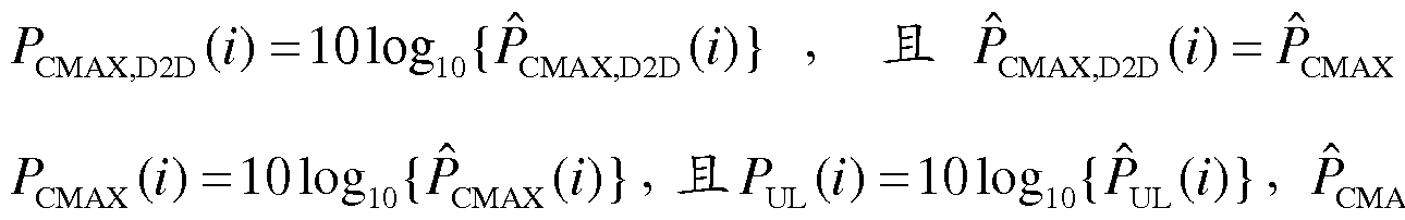 X( 为终端设备在第 个 子帧的最大发射功率的线性值, ^·)为第 个子帧上行蜂窝传输的发射功率的线性 值,且^ 可以包括物理上行控制信道( Physical Uplink Control Channel, PUCCH ) 和物理上行共享信道(Physical Uplink Shared Channel, PUSCH ) 的传输功率。 在本 发明实施例中, eMAX( )和 Μ^ ·)分别代表同一个变量(即终端设备在第 个子帧
的最大发射功率) 的不同表示方式。 其中, ΜΑΧ ( )代表 dB值, c (i)代表线性 值。 同理, ^')和^(0分别代表第 个子帧上行蜂窝传输的发射功率的线性值和 dB值。 eMAX,D2D ( )和 ΜΑΧ,。2。 ( )分别为终端设备在第 i个子帧用于 D2D传输的最大 发射功率的线性值和 dB值。
X( 为终端设备在第 个 子帧的最大发射功率的线性值, ^·)为第 个子帧上行蜂窝传输的发射功率的线性 值,且^ 可以包括物理上行控制信道( Physical Uplink Control Channel, PUCCH ) 和物理上行共享信道(Physical Uplink Shared Channel, PUSCH ) 的传输功率。 在本 发明实施例中, eMAX( )和 Μ^ ·)分别代表同一个变量(即终端设备在第 个子帧
的最大发射功率) 的不同表示方式。 其中, ΜΑΧ ( )代表 dB值, c (i)代表线性 值。 同理, ^')和^(0分别代表第 个子帧上行蜂窝传输的发射功率的线性值和 dB值。 eMAX,D2D ( )和 ΜΑΧ,。2。 ( )分别为终端设备在第 i个子帧用于 D2D传输的最大 发射功率的线性值和 dB值。
进一步的, 终端设备还可以利用如下公式确定 /^,。2。 ( ): 尸 (0 _ lOlOgio {ΜΌ2Ό ( )) + P ·尸^ W , 其 中 ,
PO D2D为 D2D传输的目标接收功率, aD2D为补偿因子, 0≤ αΌ2Ό < 1 , Ρ1^2Ό为终端 设备与终端设备(即两个 D2D终端设备 )之间的路径损耗, ATF D2D ( )为由第 个子 帧的 D2D传输的调制阶数确定的参数, fD2D (i)为 D2D传输闭环功控命令控制的第 i 个子帧的闭环调整量。
本发明实施例中, 终端设备还可以通过基站设备发送的闭环功控命令控制的闭 环调整量对 D2D传输功率上限值进行进一步调整, 如图 4所示, 该方法包括: 步骤 401 , 终端设备接收来自基站设备的本终端设备对应的干扰功率上限值, 并利用该干扰功率上限值确定 D2D传输功率上限值; 其中, 干扰功率上限值为基站 设备允许的 D2D传输对蜂窝传输产生的最大干扰值; D2D传输功率上限值为对蜂 窝传输产生的干扰不超过干扰功率上限值的最大发射功率。
步骤 402 , 终端设备利用 D2D传输功率上限值确定 D2D传输功率。
上述步骤 401至 402与步骤 301至 302相同, 在此不再赘述。
步骤 403 , 终端设备接收来自基站设备的闭环功控命令控制的闭环调整量, 并 利用该闭环功控命令控制的闭环调整量确定 D2D 传输功率上限值, 并利用确定的 D2D传输功率上限值确定 D2D传输功率。
本发明实施例中,终端设备利用闭环功控命令控制的闭环调整量确定 D2D传输 功率上限值, 具体包括: 终端设备利用干扰功率上限值、 闭环功控命令控制的闭环 调整量以及终端设备到所述基站设备的路径损耗确定 D2D传输功率上限值。进一步 的, 终端设备利用如下公式计算 D2D传输功率上限值:
尸 (0 = A + P0— Interf— UL + a . PL + /Merf UL ( );
其中, M,D2D«是第 个子帧内的 D2D传输功率上限值, ^― Interf—^为干扰功率
上限值 (即终端设备收到的来自基站设备的干扰功率上限值), 其单位是 [dBm]; PL 为终端设备到基站设备的路径损耗; α为补偿因子, 0≤α≤1, 且 α=1是对路损的 完全补偿, α的取值是由基站设备通知给终端设备的, 或者取预先约定好的固定值, 例如预先约定好的固定值为: α = 1; fMerf UL (i)为基站设备发送给终端设备的闭环功 控命令控制的第 个子帧的闭环调整量。
本发明实施例中, 在上述公式中, A = 0或者 A = 101og1()(MD2D( )) , JLA = 0对 应计算的是 D2D传输在单位带宽上的传输功率上限值, A = 101og10( D2D ())对应计 算的是 D2D传输的传输功率上限值; 以下对此进行详细说明。
当 A = 101og1()(MD2D( ))时, lM,D2D( )是第 i个子帧内的 D2D传输带宽上的传输 功率上限值, PO Interf UL为一个基本带宽单元对应的带宽上的干扰功率上限值 (即终 端设备收到的来自基站设备的干扰功率上限值), 其单位是 [dBm]; D2D ()为第 个 子帧的 D2D传输的带宽, 即 MD2D(0为 D2D传输的带宽, 并以一定带宽为基本带宽 单元; 例如以一个 PRB的带宽为基本带宽单元, 则 MD2D(0为 D2D传输的带宽包含 的基本带宽单元的个数。
当 A = 0时, ^Μ∞。 ()是第 i个子帧内的 D2D传输带宽上的传输功率上限值,
P。― Interf— 为 D2D传输带宽上的干扰功率上限值 (即终端设备收到的来自基站设备的 干扰功率上限值), 其单位是 [dBm]; 或者, 当 A = 0时, ^Μ,。2。()是第 个子帧内的 一个基本带宽单元上的 D2D传输功率上限值, Ρ。― Interf—^为一个基本带宽单元对应的 带宽上的干扰功率上限值 (即终端设备收到的来自基站设备的干扰功率上限值), 其 单位是 [dBm]。
本发明实施例中, 终端设备利用确定的 D2D传输功率上限值确定 D2D传输功 率包括: 终端设备确定 D2D传输功率不大于 D2D传输功率上限值。
进一步的, 终端设备利用如下公式计算 D2D传输功率:
尸 D2D ('·) =
 或者 '
或者 '
ΡΌ2Ό (i) = min{PCMAXD2D ( ), A + PO Merf UL +a-PL + /Merf UL ( ), NCiD2D ( ) }; 其中, ΜΑΧ。2。()为终端设备在第 个子帧用于 D2D 传输的最大发射功率, PNQD2D( )为 D2D发射功率不受限条件下所计算出的第 个子帧的 D2D发射功率。
进一步的, Μ,。2。(0为第 个子帧的 D2D传输功率上限值, ^― Interf—^为干扰功 率上限值(即终端设备收到的来自基站设备的干扰功率上限值), a为补偿因子, 0≤«≤1, JL«=1是对路损的完全补偿, a的取值是由基站设备通知给终端设备的, 或者取预先约定好的固定值, 例如预先约定好的固定值为: a=l , PL为终端设备 到基站设备的路径损耗。 此外, A = 0或者 A = 101og10 ( D2D ( )) , MD2D ( )为第 i个子 帧的 D2D传输的带宽, 并以 PRB为单位。 此外, terf ^(0为基站设备发送给终端 设备的闭环功控命令控制的第 个子帧的闭环调整量。
进一步的, 当终端设备在 D2D传输的子帧内不进行蜂窝传输时, 终端设备确定 2 ') = ( ' ΜΑΧ(0为终端设备在第 个子帧的最大发射功率; 当终端设 备在 D2D 传 输 的 子 帧 内 进行蜂 窝 传 输 时 , 终 端 设备确 定
^CMAX,D2D (^')― 1010§lo{^CMAX,D2D (Z) 1 , 且 MAX, D 2D W _ ^CMAX (Z ) _ jL (Z) , 其 中 ,
^cMAx( = 101og10{PCMAx ")} '且 = 101Ogl。{^()} ' PCMAX(i)为终端设备在第 个 子帧的最大发射功率的线性值, ^·)为第 个子帧上行蜂窝传输的发射功率的线性 值, 且^ ( )可以包括 PUCCH和 PUSCH的传输功率。
进一步的, 终端设备还可以利用如下公式确定 ΡΝε,。2。() : 尸 ,D2D (0 _ lOlOgio W) + ^0_D2D + D2D ·尸^ D2D ,D2D 2 W , 其 中 ,
ΡΟ Ό2Ό为 D2D传输的目标接收功率, aD2D为补偿因子, 0≤ «D2D≤ 1 , 为终端 设备与终端设备(即两个 D2D终端设备 )之间的路径损耗, ATFD2D ( )为由第 个子 帧的 D2D传输的调制阶数确定的参数, fD2D(i)为 D2D传输闭环功控命令控制的第 i 个子帧的闭环调整量。
本发明实施例中, 闭环功控命令控制的闭环调整量与上行蜂窝传输的闭环功控 独立控制, 且闭环功控命令控制的闭环调整量可以以绝对值方式进行控制或者以累 计值方式进行控制。 其中, 以绝对值方式进行控制是指基站设备发送给终端设备的 闭环功控命令直接映射为闭环调整量的取值, 即 /Interf u ) = δ, 其中 由闭环功控 命令映射得到。 以累计值方式进行控制是指基站设备发送给终端设备的闭环功控命 令映射为对前一个时刻闭环调整量的修正值,即 / ^ ·) = /;^ ur^-i) + ,其中 由闭环功控命令映射得到。
基于此, 在上述过程中,基站设备可以根据 D2D传输对蜂窝传输产生的干扰情 况设置闭环功控命令。 例如,基站设备测量到 D2D终端设备到蜂窝基站的干扰功率 增加,可能是由瞬时信道增益变化导致的,因此基站设备通过闭环功控命令减小 D2D 传输功率上限值; 具体的, 基站设备可以令 取负值, 如 S = _1 [dB] , 以减小 D2D 传输功率上限值。 此外, D2D终端设备计算发射功率时使用的路损是基站设备到终 端设备的下行路损估计值, 与实际的上行路损可能存在差别, 闭环功控命令可以用 来弥补这一误差产生的影响。
综上所述, 本发明实施例中, 终端设备通过干扰功率上限值(即基站设备允许 的 D2D传输对蜂窝传输产生的最大干扰值 )确定 D2D传输功率上限值, 并利用该 D2D传输功率上限值确定 D2D传输功率, 从而能够对终端设备的 D2D传输功率进 行控制, 即控制 D2D 传输的发射功率使之对蜂窝传输产生的干扰在受控的范围之 内, 继而控制 D2D信号对蜂窝信号的干扰。 进一步的, 本发明实施例中所提出的功 率控制方法与蜂窝传输的上行功率控制是独立进行的,从而可以避免 D2D干扰控制 和蜂窝传输功率控制参数两难选择问题,继而可以有效的控制 D2D传输对蜂窝传输 产生的干扰。
基于与上述方法同样的发明构思, 本发明实施例中还提供了一种基站设备, 如 图 5所示, 该基站设备包括:
处理器 502;
存储器 504;
以及存储在所述存储器 504中的可以被处理器 502执行的多个指令模块; 所述 多个指令模块包括:
确定模块 51 , 用于确定终端设备对应的干扰功率上限值, 该干扰功率上限值为 基站设备允许的设备到设备 D2D传输对蜂窝传输产生的最大干扰值;
发送模块 52, 用于将所述干扰功率上限值发送给所述终端设备; 由所述终端设 备利用所述干扰功率上限值确定 D2D传输功率上限值。
所述确定模块 51 ,具体用于利用上行总体干扰功率和 /或蜂窝传输信号功率确定 所述终端设备对应的干扰功率上限值。
所述确定模块 51 , 进一步用于确定所述终端设备对应的干扰功率上限值为所述 上行总体干扰功率回退 X[dB] ; 或者, 确定所述终端设备对应的干扰功率上限值为
所述蜂窝传输信号功率回退 Y[dB]。
所述确定模块 51 , 还用于确定闭环功控命令控制的闭环调整量;
所述发送模块 52, 还用于将所述闭环功控命令控制的闭环调整量发送给所述终 端设备。
本发明实施例中, 所述闭环功控命令控制的闭环调整量以绝对值方式进行控制 或者以累计值方式进行控制; 其中, 以绝对值方式进行控制是指所述基站设备发送 给所述终端设备的闭环功控命令直接映射为闭环调整量的取值; 以累计值方式进行 控制是指所述基站设备发送给所述终端设备的闭环功控命令映射为对前一个时刻闭 环调整量的修正值。
其中, 本发明装置的各个模块可以集成于一体, 也可以分离部署。 上述模块可 以合并为一个模块, 也可以进一步拆分成多个子模块。
基于与上述方法同样的发明构思, 本发明实施例中还提供了一种终端设备, 如 图 6所示, 该终端设备包括:
处理器 602;
存储器 604;
以及存储在所述存储器 604中的可以被处理器 602执行的多个指令模块; 所述 多个指令模块包括:
接收模块 61 , 用于接收来自基站设备的所述终端设备对应的干扰功率上限值, 所述干扰功率上限值为所述基站设备允许的设备到设备 D2D 传输对蜂窝传输产生 的最大干扰值; 第一确定模块 62, 用于利用所述干扰功率上限值确定 D2D传输功 率上限值; 第二确定模块 63, 用于利用 D2D传输功率上限值确定 D2D传输功率。
所述第一确定模块 62, 具体用于利用所述干扰功率上限值以及所述终端设备到 所述基站设备的路径损耗确定所述 D2D传输功率上限值。
所述第一确定模块 62, 具体用于利用如下公式计算 D2D传输功率上限值: 尸 LM,D2D ('·) = A + ·Ρ。— Interf— UL + a . PL;
其中, M,mD ( 为第 个子帧的 D2D传输功率上限值, PO Merf UL为所述干扰功 率上限值, α为补偿因子, 0≤α≤1 , PL为所述终端设备到所述基站设备的路径损 耗, 1 = 0或者^ = 101081。( 。2。( , MD2D ( )为第 个子帧的 D2D传输的带宽。
所述第二确定模块 63, 具体用于确定所述 D2D传输功率不大于所述 D2D传输
功率上限值。
所述第二确定模块 63, 具体用于利用如下公式计算所述 D2D传输功率:
尸 D2D ('·) =
 尸 LM,D2D 尸 N D2D ( I, 或者 '
^D2D ('·) = min{PcMAX,D2D (0, ^ +尸。— Interf— UL + °- · 尸 N D2D W I;
其中, ΜΑΧ,。2。()为终端设备在第 个子帧用于 D2D 传输的最大发射功率,
PNQD2D( )为 D2D发射功率不受限条件下所计算出的第 个子帧的 D2D发射功率;
PLM,D2D (0 =A + 0 eRF_UL + « · ,且 Μ,。2。 ()为第 i个子顿的 D2D传输功率上限 值, ― UL为所述干扰功率上限值, "为补偿因子, 0≤«≤1, PL为所述终端设 备到所述基站设备的路径损耗, A = 0或者 A = 101og10( D2D ( )) , D2D( 为第 i个子 帧的 D2D传输的带宽。
所述接收模块 61 , 还用于接收来自所述基站设备的闭环功控命令控制的闭环调 整量; 所述第一确定模块 62, 还用于利用所述闭环功控命令控制的闭环调整量确定
D2D传输功率上限值; 所述第二确定模块 63, 还用于利用确定的 D2D传输功率上 限值确定 D2D传输功率。
所述第一确定模块 62, 具体用于利用所述干扰功率上限值、 所述闭环功控命令 控制的闭环调整量以及所述终端设备到所述基站设备的路径损耗确定 D2D传输功 率上限值。
所述第一确定模块 62, 具体用于利用如下公式计算所述 D2D传输功率上限值: 尸 LM,D2D (0 = A + P0— Interf— UL + a . PL + /Interf UL ( );
其中, Μ,。2。 ()为第 个子帧的 D2D传输功率上限值, PO Merf UL为所述干扰功 率上限值, α为补偿因子, 0≤α≤1, PL为所述终端设备到所述基站设备的路径损 耗, / UL ( 为所述基站设备发送给所述终端设备的闭环功控命令控制的第 i个子 帧的闭环调整量, ^ = 0或者^ = 101081。( 。2。( , MD2D( )为第 个子帧的 D2D传 输的带宽。
所述第二确定模块 63, 具体用于确定所述 D2D传输功率不大于所述 D2D传输 功率上限值。
所述第二确定模块 63, 具体用于利用如下公式计算所述 D2D传输功率:
尸 D2D ('·) =
 尸 LM,D2D 尸 N D2D W I; 或者 '
 W I; 其中, ΜΑΧ,。2。()为终端设备在第 个子帧用于 D2D 传输的最大发射功率, PN D2D(i)为 D2D发射功率不受限条件下所计算出的第 个子帧的 D2D发射功率;
2 (0 = Λ + P0_im +a-PL + /Merf UL () , 且 Μ 《为第 个子帧的 D2D传 输功率上限值, Ρ。― Interf— 为所述干扰功率上限值, α为补偿因子, 0≤α≤ 1 , PL为 所述终端设备到所述基站设备的路径损耗, /Interf ^ ()为所述基站设备发送给所述终 端设备的闭环功控命令控制的第 个子帧的闭环调整量, A = 0或者 A = 101og10( D2D( )) , MD2D( )为第 个子帧的 D2D传输的带宽。
所述第二确定模块 63, 进一步用于当所述终端设备在 D2D传输的子帧内不进 行蜂窝传输时, 确定 皿, (0 = 4皿(0, ΜΑΧ(ο为所述终端设备在第 个子帧的 最大发射功率; 当所述终端设备在 D2D 传输的子帧内进行蜂窝传输时, 确定
 (Z ) _ (Z) , 其 中 ,
^CMAx( =101Og10{PCMAx ")} ' 且 =101Ogl。{ ^)} ' ( 为所述终端设备在 第 个子帧的最大发射功率的线性值, 为第 个子帧上行蜂窝传输的发射功率 的线性值。
所述第二确定模块 63 , 进一步用于利用如下公式确定 ΡΝε,。2。 ( ): 尸 NC,D2D (0 _ lOlOgio W) + _D2D + D2D ·尸^ D2D + ^TF,D2D (^) + W, 其中, p。― mD为 D2D传输的目标接收功率, «D2D为补偿因子, 0≤ aD2D≤ 1, 为终端设备与终端设备之间的路径损耗, ATFD2D ( )为由第 个子帧的 D2D传输的调 制阶数确定的参数, fD2D(i)为 D2D传输闭环功控命令控制的第 个子帧的闭环调整 量。
本发明实施例中, 所述闭环功控命令控制的闭环调整量以绝对值方式进行控制 或者以累计值方式进行控制; 其中, 以绝对值方式进行控制是指所述基站设备发送 给所述终端设备的闭环功控命令直接映射为闭环调整量的取值; 以累计值方式进行 控制是指所述基站设备发送给所述终端设备的闭环功控命令映射为对前一个时刻闭
环调整量的修正值。
本发明实施例中,所述 D2D传输功率上限值为对蜂窝传输产生的干扰不超过所 述干扰功率上限值的最大发射功率。
其中, 本发明装置的各个模块可以集成于一体, 也可以分离部署。 上述模块可 以合并为一个模块, 也可以进一步拆分成多个子模块。
通过以上的实施方式的描述, 本领域的技术人员可以清楚地了解到本发明 可借助软件加必需的通用硬件平台的方式来实现, 当然也可以通过硬件, 但很 多情况下前者是更佳的实施方式。 基于这样的理解, 本发明的技术方案本质上 软件产品存储在一个存储介质中, 包括若干指令用以使得一台计算机设备 (可 以是个人计算机, 服务器, 或者网络设备等) 执行本发明各个实施例所述的方 法。
本领域技术人员可以理解附图只是一个优选实施例的示意图, 附图中的模 块或流程并不一定是实施本发明所必须的。
本领域技术人员可以理解实施例中的装置中的模块可以按照实施例描述进 行分布于实施例的装置中, 也可以进行相应变化位于不同于本实施例的一个或 多个装置中。 上述实施例的模块可以合并为一个模块, 也可以进一步拆分成多 个子模块。
上述本发明实施例序号仅仅为了描述, 不代表实施例的优劣。
以上公开的仅为本发明的几个具体实施例, 但是, 本发明并非局限于此, 任何本领域的技术人员能思之的变化都应落入本发明的保护范围。
Claims
1、 一种设备到设备 D2D传输的功率控制方法, 其特征在于, 包括: 基站设备确定终端设备对应的干扰功率上限值, 所述干扰功率上限值为所述基 站设备允许的 D2D传输对蜂窝传输产生的最大干扰值;
所述基站设备将所述干扰功率上限值发送给所述终端设备; 使得所述终端设备 利用所述干扰功率上限值确定 D2D传输功率上限值。
2、 如权利要求 1所述的方法, 其特征在于, 所述基站设备确定终端设备对应的 干扰功率上限值, 包括:
所述基站设备利用上行总体干扰功率和 /或蜂窝传输信号功率确定所述终端设 备对应的干扰功率上限值。
3、 如权利要求 2所述的方法, 其特征在于, 所述基站设备确定终端设备对应的 干扰功率上限值, 包括:
所述基站设备确定所述终端设备对应的干扰功率上限值为所述上行总体干扰功 率回退 X[dB]; 或者, 所述基站设备确定所述终端设备对应的干扰功率上限值为所 述蜂窝传输信号功率回退 Y[dB]。
4、 如权利要求 1所述的方法, 其特征在于, 所述方法还包括:
所述基站设备确定闭环功控命令控制的闭环调整量, 并将所述闭环功控命令控 制的闭环调整量发送给所述终端设备。
5、 如权利要求 4所述的方法, 其特征在于, 所述闭环功控命令控制的闭环调整 量以绝对值方式进行控制或者以累计值方式进行控制;
其中, 以绝对值方式进行控制是指所述基站设备发送给所述终端设备的闭环功 控命令直接映射为闭环调整量的取值;
以累计值方式进行控制是指所述基站设备发送给所述终端设备的闭环功控命令 映射为对前一个时刻闭环调整量的修正值。
6、 一种设备到设备 D2D传输的功率控制方法, 其特征在于, 包括: 终端设备接收来自基站设备的所述终端设备对应的干扰功率上限值, 所述干扰 功率上限值为所述基站设备允许的 D2D传输对蜂窝传输产生的最大干扰值;
所述终端设备利用所述干扰功率上限值确定 D2D传输功率上限值,并利用所述 D2D传输功率上限值确定 D2D传输功率。
7、 如权利要求 6所述的方法, 其特征在于, 所述终端设备利用所述干扰功率上 限值确定 D2D传输功率上限值, 包括:
所述终端设备利用所述干扰功率上限值以及所述终端设备到所述基站设备的路 径损耗确定所述 D2D传输功率上限值。
8、 如权利要求 7所述的方法, 其特征在于, 所述终端设备利用所述干扰功率上 限值以及所述终端设备到所述基站设备的路径损耗确定所述 D2D传输功率上限值, 包括:
所述终端设备利用如下公式计算所述 D2D传输功率上限值:
尸 LM,D2D (0 = A + Interf— UL + a . PL;
其中, Μ,。2。 ( )为第 个子帧的 D2D传输功率上限值, PO Merf UL为所述干扰功 率上限值, α为补偿因子, 0≤α≤1 , PL为所述终端设备到所述基站设备的路径损 耗, 1 = 0或者^ = 101081。( 。2。( , MD2D ( )为第 个子帧的 D2D传输的带宽。
9、 如权利要求 6所述的方法, 其特征在于, 所述终端设备利用所述 D2D传输 功率上限值确定 D2D传输功率, 包括:
所述终端设备确定所述 D2D传输功率不大于所述 D2D传输功率上限值。
10、 如权利要求 9所述的方法, 其特征在于, 所述终端设备确定所述 D2D传输 功率不大于所述 D2D传输功率上限值, 包括:
所述终端设备利用如下公式计算所述 D2D传输功率:
尸 D2D ('·) =
 或者 '
或者 '
^D2D ('·) = MIN{^CMAX,D2D ( , A + PO Merf uL + a■ PL, Ρ ( ) };
其中, ΜΑΧ,。2。( )为终端设备在第 个子帧用于 D2D 传输的最大发射功率, PNQD2D ( )为 D2D发射功率不受限条件下所计算出的第 个子帧的 D2D发射功率; 華 D d) = A + PO MeiiJJL + « · PL , 且 PL華 D «为第 个子帧的 D 传输功率上限 值, ― UL为所述干扰功率上限值, "为补偿因子, 0≤«≤1 , PL为所述终端设 备到所述基站设备的路径损耗, ^ = 0或者^ = 1010&。( 。2。( , MD2D ( )为第 个子 帧的 D2D传输的带宽。
11、 如权利要求 6所述的方法, 其特征在于, 所述方法还包括:
所述终端设备接收来自所述基站设备的闭环功控命令控制的闭环调整量, 并利
用所述闭环功控命令控制的闭环调整量确定 D2D 传输功率上限值, 并利用确定的 D2D传输功率上限值确定 D2D传输功率。
12、 如权利要求 11所述的方法, 其特征在于, 所述终端设备利用所述闭环功控 命令控制的闭环调整量确定 D2D传输功率上限值, 包括:
所述终端设备利用所述干扰功率上限值、 闭环功控命令控制的闭环调整量以及 终端设备到所述基站设备的路径损耗确定 D2D传输功率上限值。
13、 如权利要求 12所述的方法, 其特征在于, 所述终端设备利用所述干扰功率 上限值、 闭环功控命令控制的闭环调整量以及终端设备到所述基站设备的路径损耗 确定 D2D传输功率上限值, 包括:
所述终端设备利用如下公式计算所述 D2D传输功率上限值:
尸 (0 = A + P0— Interf— UL + a . PL + /Merf UL ( );
其中, M,mD ( 为第 个子帧的 D2D传输功率上限值, PO Interf UL为所述干扰功 率上限值, α为补偿因子, 0≤α≤1 , PL为所述终端设备到所述基站设备的路径损 耗, / ( 为所述基站设备发送给所述终端设备的闭环功控命令控制的第 i个子 帧的闭环调整量, 1 = 0或者^ = 101081。( 。2。( , MD2D ( )为第 个子帧的 D2D传 输的带宽。
14、 如权利要求 11所述的方法, 其特征在于, 所述终端设备利用确定的 D2D 传输功率上限值确定 D2D传输功率, 包括:
所述终端设备确定所述 D2D传输功率不大于所述 D2D传输功率上限值。
15、 如权利要求 14所述的方法, 其特征在于, 所述终端设备确定所述 D2D传 输功率不大于所述 D2D传输功率上限值, 包括:
所述终端设备利用如下公式计算所述 D2D传输功率:
尸 ('·) = min{ ^CMAX 尸 LM 尸 ( I, 或者 '
('·) = mini (0, ^ +尸。— Interf— UL + ;■ PL + (0, W I; 其中, ΜΑΧ,。2。( )为终端设备在第 个子帧用于 D2D 传输的最大发射功率,
PN D2D (i)为 D2D发射功率不受限条件下所计算出的第 个子帧的 D2D发射功率;
^LM ( = Λ + 0 erf_UL + a■ PL + f^i JL (ί) , 且 /^ 《为第 个子帧的 D2D传
输功率上限值, Ρ。Ιη ΐΛ为所述干扰功率上限值, α为补偿因子, 0≤α≤1, PL为 所述终端设备到所述基站设备的路径损耗, /Interf ^ ()为所述基站设备发送给所述终 端设备的闭环功控命令控制的第 个子帧的闭环调整量, A = 0或者 A = 101og10( D2D( )) , MD2D( )为第 个子帧的 D2D传输的带宽。
16、 如权利要求 10或 15所述的方法, 其特征在于, 该方法进一步包括: 当所述终端设备在 D2D传输的子帧内不进行蜂窝传输时, 所述终端设备确定 CMAX,D2D ( ) = CMAX (i), ^CMAX (i)为所述终端设备在第 i个子帧的最大发射功率; 当所述终端设备在 D2D 传输的子帧内进行蜂窝传输时, 所述终端设备确定
^CMAX,D2D (^')― 1010§lo{^CMAX,D2D (Z) 1 , 且 MAX, D 2D W _ ^CMAX (Z ) _ jL (Z) , 其 中 ,
 , 为所述终端设备在 第 个子帧的最大发射功率的 dB值, ^(0为第 个子帧上行蜂窝传输的发射功率的 dB值; eMAX()为终端设备在第 个子帧的最大发射功率的线性值, 为第 个 子帧上行蜂窝传输的发射功率的线性值。
17、 如权利要求 10或 15所述的方法, 其特征在于, 该方法进一步包括: 所述终端设备利用如下公式确定 ΡΝ 2 ( ): 尸 ,D2D (0 _ lOlOgio
 + D2D ·尸^ D2D ,D2D 2 W, 其中, p。― mD为 D2D传输的目标接收功率, «D2D为补偿因子, 0≤ aD2D≤ 1, ΡΙ^2Ό 为终端设备与终端设备之间的路径损耗, ATFD2D ( )为由第 个子帧的 D2D传输的调 制阶数确定的参数, fmD(i)为 D2D传输闭环功控命令控制的第 个子帧的闭环调整 量。
18、 如权利要求 11至 15任一项所述的方法, 其特征在于, 所述闭环功控命令 控制的闭环调整量以绝对值方式进行控制或者以累计值方式进行控制;
其中, 以绝对值方式进行控制是指所述基站设备发送给所述终端设备的闭环功 控命令直接映射为闭环调整量的取值;
以累计值方式进行控制是指所述基站设备发送给所述终端设备的闭环功控命令 映射为对前一个时刻闭环调整量的修正值。
19、 如权利要求 6至 15任一项所述的方法, 其特征在于,
所述 D2D 传输功率上限值为对蜂窝传输产生的干扰不超过所述干扰功率上限 值的最大发射功率。
20、 一种基站设备, 其特征在于, 包括: 处理器; 存储器; 以及存储在所述存 储器中的可以被处理器执行的多个指令模块; 所述多个指令模块包括:
确定模块, 用于确定终端设备对应的干扰功率上限值, 所述干扰功率上限值为 基站设备允许的设备到设备 D2D传输对蜂窝传输产生的最大干扰值;
发送模块, 用于将所述干扰功率上限值发送给所述终端设备; 使得所述终端设 备利用所述干扰功率上限值确定 D2D传输功率上限值。
21、 如权利要求 20所述的基站设备, 其特征在于,
所述确定模块, 具体用于利用上行总体干扰功率和 /或蜂窝传输信号功率确定所 述终端设备对应的干扰功率上限值。
22、 如权利要求 21所述的基站设备, 其特征在于,
所述确定模块, 进一步用于确定所述终端设备对应的干扰功率上限值为所述上 行总体干扰功率回退 X[dB]; 或者, 确定所述终端设备对应的干扰功率上限值为所 述蜂窝传输信号功率回退 Y[dB]。
23、 如权利要求 20所述的基站设备, 其特征在于,
所述确定模块, 还用于确定闭环功控命令控制的闭环调整量;
所述发送模块, 还用于将所述闭环功控命令控制的闭环调整量发送给所述终端 设备。
24、 如权利要求 23所述的基站设备, 其特征在于, 所述闭环功控命令控制的闭 环调整量以绝对值方式进行控制或者以累计值方式进行控制;
其中, 以绝对值方式进行控制是指基站设备发送给所述终端设备的闭环功控命 令直接映射为闭环调整量的取值;
以累计值方式进行控制是指基站设备发送给所述终端设备的闭环功控命令映射 为对前一个时刻闭环调整量的修正值。
25、 一种终端设备, 其特征在于, 包括: 处理器; 存储器; 以及存储在所述存 储器中的可以被处理器执行的多个指令模块; 所述多个指令模块包括:
接收模块, 用于接收来自基站设备的所述终端设备对应的干扰功率上限值, 所 述干扰功率上限值为所述基站设备允许的设备到设备 D2D 传输对蜂窝传输产生的
最大干扰值;
第一确定模块, 用于利用所述干扰功率上限值确定 D2D传输功率上限值; 第二确定模块, 用于利用所述 D2D传输功率上限值确定 D2D传输功率。
26、 如权利要求 25所述的终端设备, 其特征在于,
所述第一确定模块, 具体用于利用所述干扰功率上限值以及所述终端设备到所 述基站设备的路径损耗确定所述 D2D传输功率上限值。
27、 如权利要求 26所述的终端设备, 其特征在于,
所述第一确定模块, 具体用于利用如下公式计算 D2D传输功率上限值:
尸 ('·) = A + ·Ρ。— Interf— UL + a . PL;
其中, Μ,。2。 ( )为第 个子帧的 D2D传输功率上限值, PO Merf UL为所述干扰功 率上限值, α为补偿因子, 0≤α≤1 , PL为所述终端设备到所述基站设备的路径损 耗, 1 = 0或者^ = 101081。( 。2。( , MD2D ( )为第 个子帧的 D2D传输的带宽。
28、 如权利要求 25所述的终端设备, 其特征在于,
所述第二确定模块, 具体用于确定所述 D2D传输功率不大于所述 D2D传输功 率上限值。
29、 如权利要求 28所述的终端设备, 其特征在于,
所述第二确定模块, 具体用于利用如下公式计算所述 D2D传输功率:
尸 ('·) = mi 尸 尸 W I; 或者 '
('·) = min{PcMAX (0, ^ +尸。— °- · 尸 W I;
其中, ΜΑΧ,。2。( )为终端设备在第 个子帧用于 D2D 传输的最大发射功率,
PNQD2D ( )为 D2D发射功率不受限条件下所计算出的第 个子帧的 D2D发射功率; d) = A + PO Merf UL + « · PL ,且 D2D ( )为第 个子帧的 D2D传输功率上限 值, P。― 为所述干扰功率上限值, 《为补偿因子, 0≤α≤1 , PL为所述终端设 备到所述基站设备的路径损耗, ^ = 0或者^ = 1010&。( 。2。( , MD2D ( )为第 个子 帧的 D2D传输的带宽。
30、 如权利要求 25所述的终端设备, 其特征在于,
所述接收模块, 还用于接收来自所述基站设备的闭环功控命令控制的闭环调整 量;
所述第一确定模块, 还用于利用所述闭环功控命令控制的闭环调整量确定 D2D 传输功率上限值;
所述第二确定模块, 还用于利用确定的 D2D传输功率上限值确定 D2D传输功 率。
31、 如权利要求 30所述的终端设备, 其特征在于,
所述第一确定模块, 具体用于利用所述干扰功率上限值、 所述闭环功控命令控 制的闭环调整量以及所述终端设备到所述基站设备的路径损耗确定 D2D传输功率 上限值。
32、 如权利要求 31所述的终端设备, 其特征在于,
所述第一确定模块, 具体用于利用如下公式计算所述 D2D传输功率上限值: 尸 (0 = A + P0— Interf— UL + a . PL + /Merf UL ( );
其中, M,mD ( 为第 个子帧的 D2D传输功率上限值, PO Interf UL为所述干扰功 率上限值, α为补偿因子, 0≤α≤1 , PL为所述终端设备到所述基站设备的路径损 耗, / ( 为所述基站设备发送给所述终端设备的闭环功控命令控制的第 i个子 帧的闭环调整量, 1 = 0或者^ = 101081。( 。2。( , MD2D ( )为第 个子帧的 D2D传 输的带宽。
33、 如权利要求 30所述的终端设备, 其特征在于,
所述第二确定模块, 具体用于确定所述 D2D传输功率不大于所述 D2D传输功 率上限值。
34、 如权利要求 33所述的终端设备, 其特征在于,
所述第二确定模块, 具体用于利用如下公式计算所述 D2D传输功率:
尸 ('·) = mi 尸 尸 ( I, 或者 '
('·) =
 + ;■ PL + (0, W I; 其中, ΜΑΧ,。2。( )为终端设备在第 个子帧用于 D2D 传输的最大发射功率, PN D2D (i)为 D2D发射功率不受限条件下所计算出的第 i个子帧的 D2D发射功率;
(0 = A + P0_im + a - PL + /Merf UL ( ) , 且 Μ 《为第 个子帧的 D2D传 输功率上限值, Ρ。― Interf— 为所述干扰功率上限值, α为补偿因子, 0≤α≤1 , PL为
所述终端设备到所述基站设备的路径损耗, /Interf ^ ()为所述基站设备发送给所述终 端设备的闭环功控命令控制的第 个子帧的闭环调整量, A = 0或者 A = 101og10( D2D( ) , MD2D( )为第 个子帧的 D2D传输的带宽。
35、 如权利要求 29或 34所述的终端设备, 其特征在于,
所述第二确定模块,进一步用于当所述终端设备在 D2D传输的子帧内不进行蜂 窝传输时, 确定 ΜΑΧ,。2。(0 = CMAx( , ^CMAX( 为所述终端设备在第 i个子帧的最大 发射功率; 当所述终端设备在 D2D 传输的子帧内进行蜂窝传输时, 确定
^CMAX,D2D (^')― 1010§lo{^CMAX,D2D (Z) 1 , 且 MAX, D 2D W _ ^CMAX (Z ) _ jL (Z) , 其 中 , = 101og10{PCMAx ")} ' P^d) = 101og10{PUL( )} ' PCMAX(i)为所述终端设备在第 i 个子帧的最大发射功率的 dB值, 为第 个子帧上行蜂窝传输的发射功率的 dB 值; eMAX()为终端设备在第 个子帧的最大发射功率的线性值, 为第 个子帧 上行蜂窝传输的发射功率的线性值。
36、 如权利要求 29或 34所述的终端设备, 其特征在于,
所述第二确定模块, 进一步用于利用如下公式确定 i^^D ( ): 尸 ,D2D (0 _ lOlOgio (^Ό2Ό W) + ^0_D2D + D2D ·尸^ D2D ,D2D 2 W,
其中, p。― mD为 D2D传输的目标接收功率, «D2D为补偿因子, 0≤ aD2D≤ 1, Ρ1^2Ό 为终端设备与终端设备之间的路径损耗, ATFD2D ( )为由第 个子帧的 D2D传输的调 制阶数确定的参数, fD2D(i)为 D2D传输闭环功控命令控制的第 个子帧的闭环调整 量。
37、 如权利要求 30至 34任一项所述的终端设备, 其特征在于, 所述闭环功控 命令控制的闭环调整量以绝对值方式进行控制或者以累计值方式进行控制;
其中, 以绝对值方式进行控制是指所述基站设备发送给所述终端设备的闭环功 控命令直接映射为闭环调整量的取值;
以累计值方式进行控制是指所述基站设备发送给所述终端设备的闭环功控命令 映射为对前一个时刻闭环调整量的修正值。
38、 如权利要求 25至 34任一项所述的终端设备, 其特征在于,
所述 D2D传输功率上限值为对蜂窝传输产生的干扰不超过所述干扰功率上限值
的最大发射功率。
Priority Applications (2)
| Application Number | Priority Date | Filing Date | Title |
|---|---|---|---|
| EP14782717.4A EP2986061A1 (en) | 2013-04-10 | 2014-03-18 | Power control method and device for device to device (d2d)transmission |
| US14/783,847 US9661586B2 (en) | 2013-04-10 | 2014-03-18 | Power control method and device for device to device (D2D) transmission |
Applications Claiming Priority (2)
| Application Number | Priority Date | Filing Date | Title |
|---|---|---|---|
| CN201310123605.5 | 2013-04-10 | ||
| CN201310123605.5A CN104105181B (zh) | 2013-04-10 | 2013-04-10 | 一种d2d传输的功率控制方法和设备 |
Publications (1)
| Publication Number | Publication Date |
|---|---|
| WO2014166327A1 true WO2014166327A1 (zh) | 2014-10-16 |
Family
ID=51672892
Family Applications (1)
| Application Number | Title | Priority Date | Filing Date |
|---|---|---|---|
| PCT/CN2014/073566 Ceased WO2014166327A1 (zh) | 2013-04-10 | 2014-03-18 | 一种设备到设备(d2d)传输的功率控制方法和设备 |
Country Status (4)
| Country | Link |
|---|---|
| US (1) | US9661586B2 (zh) |
| EP (1) | EP2986061A1 (zh) |
| CN (1) | CN104105181B (zh) |
| WO (1) | WO2014166327A1 (zh) |
Cited By (1)
| Publication number | Priority date | Publication date | Assignee | Title |
|---|---|---|---|---|
| JP2017538352A (ja) * | 2014-11-27 | 2017-12-21 | ミアオ、グヲンMIAO, Guowang | 移動通信ネットワークにおける近隣サービスを実現する方法及び装置 |
Families Citing this family (16)
| Publication number | Priority date | Publication date | Assignee | Title |
|---|---|---|---|---|
| WO2016022065A1 (en) * | 2014-08-08 | 2016-02-11 | Telefonaktiebolaget L M Ericsson (Publ) | D2d power control |
| WO2016119231A1 (zh) * | 2015-01-30 | 2016-08-04 | 华为技术有限公司 | 一种功率控制方法及设备 |
| CN105992327B (zh) | 2015-03-06 | 2019-05-24 | 中兴通讯股份有限公司 | 一种传输数据的方法和装置 |
| US20190028978A1 (en) * | 2015-09-01 | 2019-01-24 | Ntt Docomo, Inc. | User apparatus, base station, communication method, and communication indication method |
| CN105680925A (zh) * | 2016-03-04 | 2016-06-15 | 上海师范大学 | 一种基于干扰对齐的d2d用户的功率控制方法 |
| CN107371119A (zh) * | 2016-05-13 | 2017-11-21 | 索尼公司 | 电子装置、信息处理设备和信息处理方法 |
| EP4167652A1 (en) * | 2016-08-16 | 2023-04-19 | IPCom GmbH & Co. KG | Reuse of transmission resources for device to device communication |
| US9986513B1 (en) * | 2016-12-31 | 2018-05-29 | Sprint Communications Company L.P. | Device to-device (D2D) transmission power control |
| CN110149689B (zh) * | 2018-02-11 | 2022-03-25 | 华为技术有限公司 | 一种功率控制的方法和装置 |
| CN110381574A (zh) * | 2018-04-12 | 2019-10-25 | 维沃移动通信有限公司 | 旁链路通信中的开环功率控制方法和设备 |
| US20210410084A1 (en) * | 2018-11-08 | 2021-12-30 | Convida Wireless, Llc | Sidelink transmit power control for new radio v2x |
| KR102855276B1 (ko) | 2019-01-10 | 2025-09-05 | 삼성전자주식회사 | 무선 통신 시스템에서 전력 제어 방법 및 장치 |
| CN114845370B (zh) | 2019-01-11 | 2024-05-14 | 华为技术有限公司 | 功率控制方法及功率控制装置 |
| US20220150848A1 (en) | 2019-03-01 | 2022-05-12 | Lenovo (Beijing) Limited | Method and apparatus for controlling transmission power on a sidelink |
| CN111867033B (zh) * | 2019-04-28 | 2022-04-08 | 大唐移动通信设备有限公司 | 一种发射功率确定方法、装置及通信设备 |
| US11122525B1 (en) * | 2020-06-24 | 2021-09-14 | Charter Communications Operating, Llc | Wireless channel access and power adjust access requests |
Citations (4)
| Publication number | Priority date | Publication date | Assignee | Title |
|---|---|---|---|---|
| CN102668686A (zh) * | 2009-12-21 | 2012-09-12 | 诺基亚公司 | 多载波网络中次系统的使用 |
| US20120294163A1 (en) * | 2011-05-19 | 2012-11-22 | Renesas Mobile Corporation | Apparatus and Method for Direct Device-to-Device Communication in a Mobile Communication System |
| CN102823311A (zh) * | 2010-05-06 | 2012-12-12 | 诺基亚公司 | D2d通信中的测量和快速功率调整 |
| CN103026676A (zh) * | 2010-09-11 | 2013-04-03 | 诺基亚公司 | 蜂窝系统上行链路中的动态自主资源分配和信道接入 |
Family Cites Families (4)
| Publication number | Priority date | Publication date | Assignee | Title |
|---|---|---|---|---|
| CN102404837B (zh) * | 2011-12-07 | 2014-08-06 | 华为技术有限公司 | 设备发射功率控制的方法、装置及系统 |
| US9338807B2 (en) | 2012-03-19 | 2016-05-10 | Futurewei Technologies, Inc. | System and method for direct mobile communications power control |
| US9030984B2 (en) * | 2013-01-17 | 2015-05-12 | Intel Corporation | Transmission power control schemes for D2D communications |
| US9125101B2 (en) * | 2013-03-08 | 2015-09-01 | Intel Corporation | Distributed power control for D2D communications |
-
2013
- 2013-04-10 CN CN201310123605.5A patent/CN104105181B/zh active Active
-
2014
- 2014-03-18 EP EP14782717.4A patent/EP2986061A1/en not_active Withdrawn
- 2014-03-18 WO PCT/CN2014/073566 patent/WO2014166327A1/zh not_active Ceased
- 2014-03-18 US US14/783,847 patent/US9661586B2/en active Active
Patent Citations (4)
| Publication number | Priority date | Publication date | Assignee | Title |
|---|---|---|---|---|
| CN102668686A (zh) * | 2009-12-21 | 2012-09-12 | 诺基亚公司 | 多载波网络中次系统的使用 |
| CN102823311A (zh) * | 2010-05-06 | 2012-12-12 | 诺基亚公司 | D2d通信中的测量和快速功率调整 |
| CN103026676A (zh) * | 2010-09-11 | 2013-04-03 | 诺基亚公司 | 蜂窝系统上行链路中的动态自主资源分配和信道接入 |
| US20120294163A1 (en) * | 2011-05-19 | 2012-11-22 | Renesas Mobile Corporation | Apparatus and Method for Direct Device-to-Device Communication in a Mobile Communication System |
Cited By (1)
| Publication number | Priority date | Publication date | Assignee | Title |
|---|---|---|---|---|
| JP2017538352A (ja) * | 2014-11-27 | 2017-12-21 | ミアオ、グヲンMIAO, Guowang | 移動通信ネットワークにおける近隣サービスを実現する方法及び装置 |
Also Published As
| Publication number | Publication date |
|---|---|
| CN104105181A (zh) | 2014-10-15 |
| EP2986061A4 (en) | 2016-02-17 |
| CN104105181B (zh) | 2018-06-05 |
| US20160057709A1 (en) | 2016-02-25 |
| US9661586B2 (en) | 2017-05-23 |
| EP2986061A1 (en) | 2016-02-17 |
Similar Documents
| Publication | Publication Date | Title |
|---|---|---|
| WO2014166327A1 (zh) | 一种设备到设备(d2d)传输的功率控制方法和设备 | |
| US10959183B2 (en) | Uplink power control method and apparatus | |
| CN104350790B (zh) | 设备到设备(d2d)交叉链路功率控制 | |
| CN104105185B (zh) | 设备到设备通信中的发射功率控制方法、装置及系统 | |
| TWI596917B (zh) | 具多天線裝置之功率控制 | |
| JP2025020175A5 (zh) | ||
| EP3284291B1 (en) | Power control in a wireless network | |
| CN103535085B (zh) | 一种上行功率控制方法、基站及用户设备 | |
| KR20160022914A (ko) | 전력 제어 방법, 사용자 기기, 및 기지국 | |
| WO2013185672A1 (zh) | 一种上行功率控制方法、终端及基站 | |
| JP2017505590A (ja) | D2d通信での送信電力制御方法およびデバイス | |
| CN103037489A (zh) | 上行信号功率控制方法及装置 | |
| WO2018059248A1 (zh) | 上行信号发送功率的处理方法及装置、基站、终端 | |
| WO2020030159A1 (zh) | 功率控制方法和装置、接收设备及存储介质 | |
| CN104105189B (zh) | 一种d2d传输的功率控制方法、系统和设备 | |
| CN104936126A (zh) | 功率控制方法和用户设备 | |
| US12219495B2 (en) | Power control for bidirectional sidelink | |
| EP2938140A1 (en) | Radio communication method, radio communication system, radio station and radio terminal | |
| CN104219753B (zh) | 上行功控方法、系统及终端 | |
| WO2025030438A1 (zh) | 通信方法、终端设备和网络设备 | |
| CN105246146B (zh) | Femtocell系统功率配置的方法及装置 | |
| KR101714580B1 (ko) | 간섭인지 기반의 d2d 통신 시스템 및 그 전력 제어 방법 | |
| CN120345199A (zh) | 基于波束成形的上行功率控制 | |
| WO2015168917A1 (zh) | 一种通信方法及设备 | |
| CN104243088A (zh) | 传输功率控制比特的发送方法、接收方法及装置 |
Legal Events
| Date | Code | Title | Description |
|---|---|---|---|
| 121 | Ep: the epo has been informed by wipo that ep was designated in this application |
Ref document number: 14782717 Country of ref document: EP Kind code of ref document: A1 |
|
| WWE | Wipo information: entry into national phase |
Ref document number: 14783847 Country of ref document: US |
|
| NENP | Non-entry into the national phase |
Ref country code: DE |
|
| REEP | Request for entry into the european phase |
Ref document number: 2014782717 Country of ref document: EP |
|
| WWE | Wipo information: entry into national phase |
Ref document number: 2014782717 Country of ref document: EP |