WO2014157310A1 - 携帯端末装置、記録媒体および補正方法 - Google Patents
携帯端末装置、記録媒体および補正方法 Download PDFInfo
- Publication number
- WO2014157310A1 WO2014157310A1 PCT/JP2014/058466 JP2014058466W WO2014157310A1 WO 2014157310 A1 WO2014157310 A1 WO 2014157310A1 JP 2014058466 W JP2014058466 W JP 2014058466W WO 2014157310 A1 WO2014157310 A1 WO 2014157310A1
- Authority
- WO
- WIPO (PCT)
- Prior art keywords
- terminal device
- walking
- user
- angular velocity
- mobile terminal
- Prior art date
Links
Images


Classifications
-
- G—PHYSICS
- G01—MEASURING; TESTING
- G01C—MEASURING DISTANCES, LEVELS OR BEARINGS; SURVEYING; NAVIGATION; GYROSCOPIC INSTRUMENTS; PHOTOGRAMMETRY OR VIDEOGRAMMETRY
- G01C25/00—Manufacturing, calibrating, cleaning, or repairing instruments or devices referred to in the other groups of this subclass
-
- G—PHYSICS
- G01—MEASURING; TESTING
- G01C—MEASURING DISTANCES, LEVELS OR BEARINGS; SURVEYING; NAVIGATION; GYROSCOPIC INSTRUMENTS; PHOTOGRAMMETRY OR VIDEOGRAMMETRY
- G01C21/00—Navigation; Navigational instruments not provided for in groups G01C1/00 - G01C19/00
- G01C21/10—Navigation; Navigational instruments not provided for in groups G01C1/00 - G01C19/00 by using measurements of speed or acceleration
- G01C21/12—Navigation; Navigational instruments not provided for in groups G01C1/00 - G01C19/00 by using measurements of speed or acceleration executed aboard the object being navigated; Dead reckoning
- G01C21/16—Navigation; Navigational instruments not provided for in groups G01C1/00 - G01C19/00 by using measurements of speed or acceleration executed aboard the object being navigated; Dead reckoning by integrating acceleration or speed, i.e. inertial navigation
-
- G—PHYSICS
- G01—MEASURING; TESTING
- G01C—MEASURING DISTANCES, LEVELS OR BEARINGS; SURVEYING; NAVIGATION; GYROSCOPIC INSTRUMENTS; PHOTOGRAMMETRY OR VIDEOGRAMMETRY
- G01C22/00—Measuring distance traversed on the ground by vehicles, persons, animals or other moving solid bodies, e.g. using odometers, using pedometers
- G01C22/006—Pedometers
-
- H—ELECTRICITY
- H04—ELECTRIC COMMUNICATION TECHNIQUE
- H04M—TELEPHONIC COMMUNICATION
- H04M2250/00—Details of telephonic subscriber devices
- H04M2250/12—Details of telephonic subscriber devices including a sensor for measuring a physical value, e.g. temperature or motion
-
- H—ELECTRICITY
- H04—ELECTRIC COMMUNICATION TECHNIQUE
- H04M—TELEPHONIC COMMUNICATION
- H04M2250/00—Details of telephonic subscriber devices
- H04M2250/52—Details of telephonic subscriber devices including functional features of a camera
Definitions
- the present invention relates to a technique for correcting (calibrating) a sensor that measures information related to the movement of an observation object (especially a pedestrian).
- a positioning technique for measuring the position of a pedestrian a GPS (Global Positioning System) technique is generally used, in which a terminal carried by the pedestrian receives radio waves from satellites.
- GPS Global Positioning System
- a relative positioning technology using a self-contained sensor such as an acceleration sensor, an angular velocity sensor, or a magnetic sensor has been proposed.
- the relative positioning by the self-contained sensor is realized, for example, by detecting the motion of the pedestrian with the self-contained sensor, estimating the traveling direction and the traveling speed, and calculating the moving vector of the pedestrian.
- Patent Document 1 describes a technique of determining the state in which the pedestrian is at rest from the movement of the pedestrian, and performing correction of the gyro bias in a period in which the pedestrian is at rest.
- Patent Document 2 describes a technique for correcting a gyro sensor by estimating the traveling direction of a pedestrian from a map.
- Patent Document 3 the traveling direction of the vehicle is calculated from the gyro sensor, and when the amount of change in the traveling direction is equal to or less than the threshold value, the traveling direction of the vehicle is regarded as a straight line.
- the technology to do is described.
- Patent Document 4 describes a technique for estimating the position of a vehicle with reference to a white line or a road sign observed from the vehicle.
- the motion of the pedestrian does not always face the direction of travel, and fluctuates relatively widely depending on the movement of the foot or arm.
- the traveling direction in the walking motion of the pedestrian is so-called macroscopically formed by combining local and complex motions such as rotation, vibration, pendulum motion, vertical motion and the like. Therefore, the technology described in Patent Document 3 is suitable for a gyro sensor for detecting a local movement, with respect to a threshold value for appropriately evaluating the amount of change in the direction of travel of a macroscopically formed pedestrian. There is a problem that it is difficult to determine as another value.
- Patent Document 3 and Patent Document 4 are techniques applied to an object such as a vehicle having little difference between local and macroscopic viewpoints of motion, and these techniques can be used as pedestrians without modification. It is difficult to apply to
- the invention according to claim 1 is a portable terminal device carried by a user, wherein the gyro sensor measures angular velocity in movement of the portable terminal device to acquire angular velocity information;
- An acceleration sensor that measures acceleration in movement of a terminal device to acquire acceleration information, a camera that captures an image of a subject around the mobile terminal during a period in which the mobile terminal device is moving, and the image information Motion direction of the user and the camera according to the vector operation element for calculating the motion vector of the subject, the angular velocity information acquired by the gyro sensor, and the acceleration information acquired by the acceleration sensor.
- a correlation determination element that determines a relative relationship with an imaging direction; and the subject calculated by the vector operation element According to the motion vector and the correlation determined by the correlation determination element, the user walks according to a straight walk determination element that determines whether the user is in a straight movement state in a walking motion and the straight walk determination element And a correction element configured to correct angular velocity information acquired by the gyro sensor in response to the determination that the vehicle is in the straight-ahead state in the state of.
- the invention of claim 2 is the portable terminal device according to the invention of claim 1, wherein the vector computing element divides the image information into a plurality of blocks each having a first size, and the plurality of blocks Each of the blocks is divided into a plurality of subblocks each having a second size smaller than the first size, and edge amounts are detected for each of the plurality of subblocks, and edge amounts in each of the plurality of blocks
- the motion vector of the subject is calculated by determining the sub-block where is the largest as the representative sub-block of each block and calculating the motion vector of the determined representative sub-block.
- the invention according to claim 3 is the portable terminal device according to the invention according to claim 2, wherein the vector computing element averages motion vectors of the representative sub-block in units of walking cycles of the user. The motion vector of the subject is determined.
- the invention according to claim 4 is the portable terminal device according to the invention according to claim 2, wherein the vector computing element calculates the motion vector of the representative sub-block at an operation timing synchronized with the walking cycle of the user. Do.
- the invention of claim 5 is the portable terminal device according to the invention of claim 4, wherein the calculation timing is determined such that the speed of the camera is at a minimum.
- the invention of claim 6 is the portable terminal device according to the invention of claim 4, wherein the calculation timing is determined to be when the feet of the user are landing.
- the invention according to claim 7 is the portable terminal device according to the invention according to claim 2, wherein the camera is moving in a period during which the portable terminal device is moving at an imaging timing synchronized with the walking cycle of the user. Take an image of a subject around you.
- the invention of claim 8 is the portable terminal device according to the invention of claim 7, wherein the imaging timing is determined so as to be when the speed of the camera is minimum.
- the invention of claim 9 is the portable terminal device according to the invention of claim 7, wherein the imaging timing is determined so as to be when the feet of the user are landing.
- the invention according to claim 10 is the portable terminal device according to the invention according to claim 3, wherein the walking cycle corresponds to a time during which the user advances the left and right legs one step at a time in the walking operation of the user. It has been decided.
- the invention according to claim 11 is the portable terminal device according to the invention according to claim 4, wherein the walking cycle corresponds to the time during which the user advances the left and right legs one step at a time in the walking operation of the user. It has been decided.
- the invention of claim 12 is the portable terminal device according to the invention of claim 1, wherein the correlation has a relationship in which the imaging direction of the camera faces the traveling direction of the user's walking motion. included.
- the invention according to claim 13 is the portable terminal device according to the invention according to claim 12, in the case where the imaging direction of the camera is directly opposed to the traveling direction by the walking operation of the user, the straight walking
- the determination element determines that the walking motion of the user is in the straight-ahead state, when the motion vector of the subject determined by the vector operation element is radial in the image information.
- the invention according to claim 14 is a portable terminal device carried by a user, wherein the gyro sensor measures angular velocity in movement of the portable terminal device to acquire angular velocity information, and acceleration in movement of the portable terminal device.
- the user measures the acceleration to obtain acceleration information, the angular velocity information acquired by the gyro sensor, and the acceleration information acquired by the acceleration sensor, by comparing the pattern in the walking motion given in advance.
- the angular velocity acquired by the gyro sensor in response to the straight walking determination element for determining whether or not the user is in the straight movement state in the walking motion, and the determination that the user is in the straight movement state in the walking state And a correction element for correcting information.
- the invention of claim 15 is the portable terminal device according to the invention of claim 14, wherein the straight walking determination element compares the pattern with the pattern according to a walking cycle in the walking motion of the user.
- the invention according to claim 16 is the portable terminal device according to the invention according to claim 15, wherein the walking cycle corresponds to a time during which the user advances the left and right legs one step at a time in the walking operation of the user. It has been decided.
- the invention according to claim 17 is a recording medium for recording a computer readable program, wherein the program is executed by a computer to cause the computer to use an gyro sensor for angular velocity in the movement of the computer.
- a step of measuring angular velocity information by measurement a step of measuring acceleration by movement of the computer by an acceleration sensor, and acquiring acceleration information, and capturing an image of a surrounding object during a period of movement of the computer by a camera Acquiring image information, calculating a motion vector of the subject based on the image information acquired by the camera, angular velocity information acquired by the gyro sensor, and acceleration information acquired by the acceleration sensor
- a correction method is performed including a step of performing and a step of correcting angular velocity information acquired by the gyro sensor in
- the invention according to claim 18 is a recording medium for recording a computer readable program, wherein the program is executed by a computer to cause the computer to use an gyro sensor for angular velocity in movement of the computer.
- a step of measuring and acquiring angular velocity information a step of measuring acceleration by movement of the computer by an acceleration sensor, and acquiring acceleration information, angular velocity information acquired by the gyro sensor and an acceleration acquired by the acceleration sensor
- the step of determining whether the user is in the straight-ahead state in the walking motion by comparing the information with the pattern in the walking motion given in advance, and according to the determination that the user is in the straight-ahead state in the walking state
- the angular velocity information obtained to perform the correction method and a step of correcting.
- the invention according to claim 19 is a correction method, which measures angular velocity in movement of a portable terminal device by a gyro sensor to acquire angular velocity information, and measures acceleration in movement of the portable terminal device by an acceleration sensor.
- a step of acquiring acceleration information a step of imaging an object around the subject during a period in which the portable terminal device is moving by a camera to acquire image information, and based on the image information acquired by the camera
- the step of calculating the motion vector of the subject and according to the angular velocity information acquired by the gyro sensor and the acceleration information acquired by the acceleration sensor, the traveling direction by the walking motion of the user and the imaging direction of the camera Determining the relative relationship of the object and the correlation between the calculated motion vector of the subject and the correlation,
- a step of determining whether the user is in a straight movement state in a walking operation and a step of correcting angular velocity information acquired by the gyro sensor in response to the determination that the user is in a straight movement state in a walking state
- the invention according to claim 20 is a correction method, comprising: learning a feature point of a pattern in a known walking motion of a user who holds the portable terminal device; and measuring an angular velocity in movement of the portable terminal device with a gyro sensor Acquiring angular velocity information, acquiring acceleration information by measuring acceleration in movement of the portable terminal device with an acceleration sensor, and acquiring angular velocity information acquired by the gyro sensor and the acceleration sensor A step of determining whether the user is in a straight advance state in a walking operation by comparing acceleration information with feature points of the pattern, and in response to a determination that the user is in a straight advance state in a walking state And correcting the angular velocity information acquired by the gyro sensor.
- the invention according to claims 1 to 13, 17 and 19 calculates the motion vector of the subject based on the image information, and angular velocity information acquired by the gyro sensor and acceleration information acquired by the acceleration sensor According to the user's walking motion and the relative relationship between the shooting direction of the camera and the camera, and according to the calculated motion vector of the subject and the correlation, whether the user is in a straight movement state in the walking motion It is possible to accurately determine whether or not the user is in the straight movement state in the walking motion by determining
- the inventions according to claims 14 to 16, 18 and 20 compare the angular velocity information acquired by the gyro sensor and the acceleration information acquired by the acceleration sensor with the pattern in the walking motion given in advance. Thus, by determining whether the user is in the straight movement state in the walking motion, it is possible to accurately determine whether the user is in the straight movement state in the walking motion and it is not necessary to provide a camera.
- FIG. 7 is a diagram illustrating accelerations ⁇ v and ⁇ w and an angular velocity ⁇ v in human walking motion. It is a figure which shows the functional block with which the portable terminal device in other preferable embodiment is equipped with the flow of data. It is a flowchart which shows the correction process performed by the portable terminal device in other preferable embodiment. It is a flowchart which shows the straight walk detection process in other preferable embodiment.
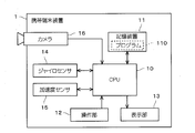
- FIG. 1 is a diagram showing a portable terminal device 1 in a preferred embodiment.
- the mobile terminal device 1 includes an operation unit 12 and a display unit 13 and is configured as a device carried by a user.
- one step in the walking motion is a motion from when a person starts raising one foot and then takes its foot forward, the foot reaches the ground, and starts raising the next foot.
- one compound step is an operation including an operation of one step on each side.
- one multi-step time is the time taken for one multi-step.
- the operation unit 12 is hardware operated by the user to give an instruction to the mobile terminal device 1.
- the operation unit 12 for example, various buttons, keys, a rotation selector, a touch panel, etc. correspond.
- the display unit 13 is hardware having a function of providing information by displaying various information to the user.
- the display unit 13 corresponds to, for example, a lamp, an LED, a liquid crystal panel, a liquid crystal display, an organic EL display, or the like.
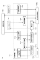
- FIG. 2 is a block diagram of the mobile terminal device 1 in the preferred embodiment.
- the portable terminal device 1 includes a CPU 10, a storage device 11, a gyro sensor 14, an acceleration sensor 15, and a camera 16 in addition to the operation unit 12 and the display unit 13 described above.
- the CPU 10 reads and executes the program 110 stored in the storage device 11, and performs operations of various data, generation of control signals, and the like.
- the CPU 10 has a function of controlling each component of the mobile terminal device 1 and calculating and creating various data. That is, the mobile terminal device 1 is configured as a general computer.
- the storage device 11 provides a function of storing various data in the mobile terminal device 1. In other words, the storage device 11 stores the electronically fixed information in the mobile terminal device 1. In particular, storage device 11 in the preferred embodiment is used to store program 110.
- the storage device 11 may be a RAM or buffer used as a temporary working area of the CPU 10, a read only ROM, a non-volatile memory (for example, a NAND memory), a hard disk for storing relatively large capacity data, a dedicated memory This corresponds to a portable storage medium (PC card, SD card, USB memory, etc.) attached to the reading device.
- a portable storage medium PC card, SD card, USB memory, etc.
- FIG. 2 it is illustrated as if the storage device 11 is a single structure.
- the storage device 11 is configured of a plurality of types of devices adopted as needed among the various devices (or media) illustrated above. That is, in the preferred embodiment, the storage device 11 is a generic name of a group of devices having a function of storing data.
- the actual CPU 10 is an electronic circuit internally provided with a RAM that can be accessed at high speed.
- the storage device included in such a CPU 10 is also included in the storage device 11 and described. That is, in the preferred embodiment, the data temporarily stored by the CPU 10 itself is also described as being stored by the storage device 11.
- the gyro sensor 14 measures the angular velocity in the movement of the mobile terminal device 1 and acquires angular velocity information 140 (see FIG. 3).
- a cycle sampling cycle in which the gyro sensor 14 acquires the angular velocity information 140 is referred to as “Ts”.
- the acceleration sensor 15 measures acceleration in movement of the mobile terminal device 1 to acquire acceleration information 150 (see FIG. 3).
- the camera 16 includes an optical element such as a lens and a mirror, and a photoelectric conversion element such as a CCD, and is configured as a general digital camera.
- the camera 16 captures an image of a subject around at least during a period in which the mobile terminal device 1 is moving, and acquires image information 160 (see FIG. 3).
- the camera 16 is configured to capture an image at a predetermined imaging timing according to a control signal from the CPU 10.
- the camera 16 in the preferred embodiment performs imaging at an imaging cycle "Tc" and acquires new image information 160.
- FIG. 3 is a diagram showing functional blocks included in the mobile terminal device 1 in the preferred embodiment together with the flow of data.
- the walking cycle calculation unit 100, the vector calculation unit 101, the correlation determination unit 102, the straight walk determination unit 103, and the correction unit 104 shown in the figure are functional blocks realized by the CPU 10 operating according to the program 110.
- the walking cycle calculation unit 100 refers to the angular velocity information 140 and the acceleration information 150 to determine the walking cycle in the walking motion of the user (pedestrian).
- the walking cycle calculation unit 100 transmits the determined walking cycle to the vector calculation unit 101 and the correction unit 104.
- the walking cycle calculation unit 100 also has a function of transmitting the traveling direction of the user to the correlation determination unit 102.
- the vector operation unit 101 has a function of calculating the motion vector of the subject in the image information 160 based on the image information 160 and creating the motion vector information 111.
- the interval at which the vector computing unit 101 computes a motion vector is hereinafter referred to as a computation interval "Tv".
- the motion vector of the subject in the image information 160 is a motion vector due to the motion of the apparent subject caused by the movement of the portable terminal 1 according to the operation of the user, and the motion vector of the subject itself. It is a combination with the motion vector generated by the motion. However, in the following description, the subject is treated as stationary, and the motion vector generated by the motion of the subject itself is ignored. Also, the vector operation unit 101 in the preferred embodiment includes the walking cycle transmitted from the walking cycle operation unit 100 in the motion vector information 111.
- the correlation determination unit 102 determines the relative relationship between the traveling direction of the user's walking motion and the imaging direction of the camera 16 according to the angular velocity information 140 acquired by the gyro sensor 14 and the acceleration information 150 acquired by the acceleration sensor 15. Determine However, although the details will be described later, the correlation determination unit 102 in the preferred embodiment utilizes the traveling direction obtained in the process of the walking cycle calculation unit 100 calculating the walking cycle based on the angular velocity information 140 and the acceleration information 150.
- the determination result by the correlation determination unit 102 is stored as correlation determination information 112.
- the straight walking determination unit 103 determines whether the user is in a straight moving state in the walking motion according to the motion vector information 111 calculated by the vector calculation unit 101 and the correlation determined by the correlation determination unit 102 (correlation determination information 112). Determine if
- the correction unit 104 has a function of correcting the bias value (bv) of the gyro sensor 14 in response to the straight walking determination unit 103 determining that the user is in the straight traveling state in the walking state.
- the correction unit 104 also has a function of correcting the angular velocity information 140 already acquired retroactively to the past.
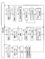
- FIG. 4 is a flow chart showing the correction process for the gyro sensor 14 in the preferred embodiment.
- another process may be performed in parallel with the process shown in FIG. 4 or sharing a part of the process.
- the other processing is, for example, positioning processing for specifying the position of the user, destination guidance processing using the result of the positioning processing, and route recording processing.
- predetermined initial setting is being performed in the mobile terminal device 1 before the process illustrated in FIG. 4 is started.
- set Ts to the measurement timer for measuring the measurement timing by the gyro sensor 14 and the acceleration sensor 15 and start Tc, and set Tc to the imaging timer for measuring the imaging timing by the camera 16.
- start processing but the operation timer is not started. This is because the process of calculating the motion vector can not be performed until at least one piece of image information 160 is acquired and a representative sub-block described later is determined.
- the initial setting includes a process of setting an initial value of the bias value (bv) of the gyro sensor 14 and a process of determining the attitude of the mobile terminal device 1 (the attitude at the start of the process).
- a method of determining the initial attitude of the portable terminal device 1 a method in which the user operates the operation unit 12 of the portable terminal device 1 to input the attitude, a method of determining the attitude by an output of a magnetic sensor not shown, etc. Be done.
- the mobile terminal device 1 When the initial setting is completed, the mobile terminal device 1 is in a state of monitoring the measurement timer, the imaging timer, and the operation timer (steps S1, S5, and S11). This state is referred to as a "monitoring state" in the following description. However, in the monitoring state, the mobile terminal device 1 may execute processing other than steps S1, S5, and S11.
- step S3 the CPU 10 determines Yes in step S1 and resets the values of the gyro sensor 14 and the acceleration sensor 15 while resetting the measurement timer to Ts (step S2). Read each one. By this, the measurement of the angular velocity and acceleration regarding the movement of the portable terminal device 1 is performed (step S3).
- the value of the gyro sensor 14 read out in step S3 is obtained based on the initial value of the bias value bv if the correction of the bias value bv (described later) has not been made. On the other hand, after the bias value bv is corrected, it is acquired as a value corrected by the value of the corrected bias value bv.
- the CPU 10 creates angular velocity information 140 and acceleration information 150 based on the read value of the gyro sensor 14 and the value of the acceleration sensor 15, and records the information in the storage device 11 (step S4).
- the angular velocity information 140 and the acceleration information 150 are recorded in the order of acquisition as a history, rather than being overwritten on past recordings.
- the portable terminal device 1 determines Yes in step S1 each time the value of the measurement timer becomes 0, and executes the processing of steps S2 to S4. Therefore, in the mobile terminal device 1, the angular velocity and the acceleration are measured for each measurement cycle Ts. In addition, if step S4 is performed, the portable terminal device 1 will return to a monitoring state again.
- step S7 the image information 160 is created, and is recorded in the storage device 11.
- step S7 it is assumed that the image information 160 is not deleted or overwritten. That is, the image information 160 is recorded in the order of imaging.
- the CPU 10 determines whether an operation timer for measuring operation timing has been started (step S8). If the arithmetic timer is not activated, the CPU 10 sets Tv in the arithmetic timer to activate (step S9), and executes representative sub-block determination processing (step S10). On the other hand, when the operation timer has already been started, steps S9 and S10 are skipped to return to the monitoring state.
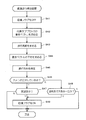
- 5 and 6 are flowcharts showing representative sub-block determination processing in the preferred embodiment.
- the vector operation unit 101 acquires the latest image information 160 and divides it into a plurality of blocks (step S21).
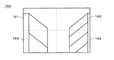
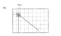
- FIG. 7 is a diagram showing how the vector information processing unit 101 divides the image information 160.
- FIG. 7 shows an example of the surrounding subject (image information 160) captured when the user travels in the aisle in which shelves for displaying goods are arranged on both sides.
- step S21 the vector operation unit 101 divides the image information 160 into a plurality of blocks each having a first size. Each block corresponds to a partial image of the image information 160. In the example shown in FIG. 7, the image information 160 is divided into four blocks of blocks 161, 162, 163, and 164.
- the vector operation unit 101 resets the value of the block counter i to "1" (step S22).
- the block counter i is a counter for identifying a block being processed. As shown in FIG. 7, since the vector operation unit 101 in the preferred embodiment divides the image information 160 into four blocks, the value of the block counter i is an integer of “1” to “4”.
- the vector operation unit 101 further divides the i-th block indicated by the block counter i into sub-blocks (step S23).
- FIG. 8 is a diagram showing how the vector operation unit 101 divides the block 161 shown in FIG. 7. Note that FIG. 8 shows the block 161 shown in FIG. 7 in an enlarged manner.
- step S23 the vector operation unit 101 divides the i-th block into a plurality of sub-blocks having a second size smaller than the first size.
- Each sub block corresponds to a partial image of the image information 160.
- the block 161 is divided into 54 subblocks.
- step S23 the vector operation unit 101 resets the value of the maximum edge amount to "0" and resets the value of the sub block counter j to "1" (step S24).
- the maximum edge amount is a variable that temporarily stores the maximum edge amount of subblocks included in the block being processed.
- the sub block counter j is a counter for identifying a sub block being processed. As shown in FIG. 8, since the vector operation unit 101 divides one block into 54 sub blocks, the value of the sub block counter j is an integer of “1” to “54”.
- the vector operation unit 101 calculates the edge amount of the j-th subblock indicated by the subblock counter j among the plurality of subblocks divided in step S23 (step S31), and determines the j-th sub obtained It is determined whether the edge amount of the block is larger than the maximum edge amount (step S32).
- step S32 the vector operation unit 101 newly sets the value of the j-th edge amount as the maximum edge amount (step S33), and sets the identifier SBi for identifying the representative sub-block in the i-th block j "is set (step S34). That is, when the edge amount of the j-th subblock is larger than the edge amounts of the first to j-1th subblocks, the edge amount of the j-th subblock is stored as the maximum edge amount. , “J” is stored in the identifier SBi.
- step S32 the vector operation unit 101 skips the processing in steps S33 and S34 because the j-th sub-block is not determined to be a representative sub-block.
- the vector operation unit 101 determines whether or not calculation and evaluation of edge amounts for all subblocks have been completed for the i-th block (step S35). In the preferred embodiment, since the number of subblocks in the i-th block is 54, for example, it may be determined whether j ⁇ 54 or not in step S35.
- step S35 If No at step S35 (if not completed for all subblocks), the vector operation unit 101 increments the value of j (step S36), and repeats the process from step S31. That is, processing for the next sub-block of the i-th block is continued.
- step S35 if the result of step S35 is Yes (if all subblocks have been completed), the vector operation unit 101 resets the value of the maximum edge amount to "0" (step S37), and the i-th block is processed. End the process. That is, the representative sub-block of the i-th block is determined to be the sub-block indicated by the identifier SBi.
- the vector operation unit 101 determines whether or not determination of a representative sub block has been completed for all blocks (step S38). In the preferred embodiment, since the number of blocks is four, for example, it may be determined whether or not i ⁇ 4 in step S38.
- step S38 If No at step S38 (if not completed for all the blocks), the vector operation unit 101 increments the value of i (step S39), and repeats the process from step S23. That is, processing for the next block is continued.
- step S38 the vector operation unit 101 ends the representative sub-block determination process, and returns to the process of FIG.
- the vector operation unit 101 detects an edge amount for each of a plurality of sub blocks, and determines a sub block having the largest edge amount in each of the plurality of blocks as a representative sub block of each block.
- the sub-block 161 a including the corner of the display shelf is determined as the representative sub-block in the block 161.
- sub blocks having the largest edge amount are also determined as representative sub blocks from among the blocks 162, 163, and 164, respectively.
- the portable terminal device 1 tries to detect the motion of the portable terminal device 1 based on the motion vector of the representative sub-block. Then, in order to calculate a motion vector, it is preferable to extract and calculate a portion (sub block) having a large amount of edges in the image.
- the vector operation unit 101 in the preferred embodiment determines a representative sub-block in each block as a sub-block in which the edge amount is maximum in the block. Therefore, the motion vector can be accurately calculated.
- the positions of the calculated motion vector in the image information 160 be dispersed. That is, it is preferable that the representative sub-block is selected from various positions in the image information 160.
- the vector operation unit 101 in the preferred embodiment divides one still image in the image information 160 into four blocks and determines representative sub-blocks from each block. It is possible to suppress the localization of subblocks for which motion vectors are to be calculated in the image information 160. Therefore, in the process to be described later, it can be accurately determined whether or not the user's traveling direction is in the straight-ahead state.
- step S11 when the operation timer becomes 0 and the operation timing comes, the CPU 10 determines Yes in step S11, and resets the operation timer to Tv (step S12) to perform straight walking detection processing Is executed (step S13).
- FIG. 9 is a flow chart showing straight walk detection processing in a preferred embodiment.
- the straight walking determination unit 103 resets the straight driving flag indicating whether the user's walking motion is straight walking to OFF (step S41).
- step S42 After the vector operation unit 101 specifies the position of each representative sub-block in the latest image information 160 and determines the representative sub-block (after the image information 160 whose representative sub-block has been determined is imaged) A motion vector of each representative sub-block in a period until the latest image information 160 is captured is obtained (step S42).
- the period from the determination of the representative sub-block to the imaging of the latest image information 160 is managed by an operation timer and is an operation cycle Tv. That is, in step S42, a motion vector between Tv is calculated.
- the imaging cycle Tc can be considered to be discrete with respect to the calculation cycle Tv, the period is n ⁇ Tc (where n ⁇ Tc ⁇ Tv ⁇ (n + 1) ⁇ Tc).
- the walking cycle calculation unit 100 obtains the walking cycle in the walking motion of the user.
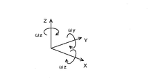
- FIG. 10 is a view showing a coordinate system of the gyro sensor 14, the acceleration sensor 15 and the camera 16.
- the gyro sensor 14, the acceleration sensor 15, and the camera 16 are all fixed. Therefore, even if the attitude of the mobile terminal device 1 changes, the relative positional relationship between the gyro sensor 14, the acceleration sensor 15, and the camera 16 does not change.
- the imaging direction of the camera 16 is taken as an X axis.
- the acceleration sensor 15 is disposed such that one of the three axes of the acceleration sensor 15 coincides with the X axis, and the other two axes are Y and Z respectively.
- the outputs of the acceleration sensor 15 become the acceleration ⁇ x in the X axis direction, the acceleration ⁇ y in the Y axis direction, and the acceleration ⁇ z in the Z axis direction.
- the gyro sensor 14 is disposed such that the three axes of the gyro sensor 14 for measuring the angular velocity around the three axes coincide with the X axis, the Y axis, and the Z axis, respectively.
- the output of the gyro sensor 14 becomes the angular velocity ⁇ x around the X axis, the angular velocity ⁇ y around the Y axis, and the angular velocity ⁇ z around the Z axis.
- the relative positional relationship (known) of the gyro sensor 14, the acceleration sensor 15, and the camera 16 does not change even if it can not be arranged in this way, so the output values of the gyro sensor 14 and the acceleration sensor 15 are known. It can be converted into values corresponding to each of the X axis, Y axis and Z axis based on the positional relationship of
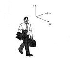
- FIG. 11 is a diagram showing a coordinate system in the walking motion of the user.
- a direction opposite to gravity is taken as a V axis
- a direction in which the user travels is taken as a W axis.
- the traveling direction of the user is defined in a horizontal plane, and the V axis and the W axis are perpendicular to each other. Further, an axis perpendicular to the W axis and the V axis is taken as an S axis.
- the walking cycle calculation unit 100 estimates a gravity direction vector based on the acceleration information 150 using a conventional Kalman filter.
- the V-axis is determined as the reverse direction of the gravity direction vector thus estimated.
- the walking cycle calculation unit 100 rotates so as to align the Z-axis with the V-axis, and acquires the rotation angle ⁇ 1 at this time.
- ⁇ y and ⁇ z are calculated while rotating 360 ° around the Z axis.
- the acceleration in the W-axis direction traveling direction
- the acceleration in the S-axis direction left-right direction with respect to the traveling direction
- the rotation angle ⁇ 2 at which ⁇ z is maximum and ⁇ y is minimum is determined while the Z axis is rotated 360 °, and the X axis and Y axis at this time are determined as the W axis and the S axis, respectively.
- the walking cycle calculation unit 100 can convert the output value of the XYZ coordinate system into the WSV coordinate system. That is, the acceleration ⁇ w in the W-axis direction, the acceleration ⁇ s in the S-axis direction, and the acceleration ⁇ v in the V-axis direction can be obtained from the accelerations ⁇ x, ⁇ y, ⁇ z. Similarly, the angular velocity ⁇ w around the W axis, the angular velocity ⁇ s around the S axis, and the angular velocity ⁇ v around the V axis can be determined from the angular velocity ⁇ x, ⁇ y, ⁇ z.
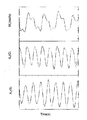
- FIG. 12 is a diagram illustrating the accelerations ⁇ v and ⁇ w and the angular velocity ⁇ v in human walking motion.
- the accelerations ⁇ v and ⁇ w have one step cycle
- the angular velocity ⁇ v has one multiple step cycle. Therefore, it can be said that it is appropriate to adopt one multi-step cycle as the cycle of the walking motion.
- the angular velocity ⁇ v changes relatively complicatedly, it is also understood that it is better to use the acceleration ⁇ v or the acceleration ⁇ w to determine the walking cycle.
- the period from when the acceleration ⁇ w takes the minimum value to when it takes the minimum value twice is one compound walking time, which is the walking cycle.
- the walking cycle computing unit 100 determines the walking cycle based on the angular velocity information 140 and the acceleration information 150. For the detection of the minimum value, for example, a zero crossing method can be employed.
- the walking cycle computing unit 100 transmits the obtained walking cycle to the vector computing unit 101. Then, the vector operation unit 101 averages the motion vector obtained in step S42 on a walking cycle basis (step S44), and sets it as a motion vector of the subject. In this manner, the vector operation unit 101 can suppress the influence of motions other than the motion in the traveling direction by obtaining the motion vector of the subject.
- the correlation determination unit 102 obtains the traveling direction of the user (step S45).
- the traveling direction is determined as the W-axis direction by the walking cycle computing unit 100 when step S43 is executed. Therefore, the correlation determination unit 102 in the preferred embodiment does not obtain the traveling direction from the angular velocity information 140 and the acceleration information 150 again in step S45, but uses the W-axis direction transmitted from the walking cycle calculation unit 100.
- step S45 the correlation determination unit 102 determines whether the camera 16 is directly facing the traveling direction from the relationship between the X axis (the direction of the camera 16) and the W axis (the traveling direction).
- the determination result is stored in the storage device 11 as the correlation determination information 112 (step S46).
- the correlation determination information 112 is referred to by the straight walking determination unit 103.
- step S46 the straight walking determination unit 103 determines whether the motion vector of the subject obtained by the vector calculation unit 101 in step S44 is radial from the center of the image information 160. (Step S47). Then, if it is radial (Yes in step S47), it is determined that the user's walking motion is straight ahead, and the straight ahead flag is set to ON (step S49), and the straight ahead walking detection processing is ended. If it is not radial (No in step S47), it is determined that the user's walking motion is not in the straight movement state, and the straight movement flag is kept OFF and the straight walking detection processing is ended.
- the straight walking determination unit 103 determines that the motion vector of the subject determined by the vector calculation unit 101 in step S44 is opposite to the traveling direction, and the walking motion It is determined whether or not the magnitude is substantially constant in a period in which there is no change in (step S48). Then, in the case of Yes in step S48, the straight walking determination unit 103 determines that the user's walking motion is in the straight driving state, sets the straight driving flag to ON (step S49), and ends the straight walking detection processing. In the case of No in step S48, the straight walking determination unit 103 determines that the user's walking motion is not in the straight driving state, and maintains the straight driving flag as OFF, and ends the straight walking detection processing.
- the straight walking determination unit 103 transmits the state of the straight traveling flag to the correction unit 104. Then, based on this, the correction unit 104 determines whether the walking state of the user is the straight going state (step S14).
- the correction unit 104 corrects the bias value of the gyro sensor 14 (Step S15).
- the principle of the correction unit 104 correcting the bias value of the gyro sensor 14 in step S15 will be described.
- an angular velocity ⁇ v which is a basis for determining the traveling direction, is one multi-step cycle. Therefore, the correction unit 104 first obtains the amount of change ( ⁇ W) in the direction of travel per multiple steps.
- step S15 is executed, and the bias value bv of the gyro sensor 14 is corrected by the correction unit 104. Therefore, thereafter, the angular velocity information 140 output from the gyro sensor 14 is corrected.
- the angular velocity information 140 is determined while the straight walking determination unit 103 determines that the walking operation of the user is in the straight traveling state. It is preferable to record the amount of change in the traveling direction as “0” without referring to the acceleration information 150.
- step S14 when the user's walking motion is not in the straight-ahead state, the correction unit 104 skips step S15 and does not correct the bias value bv of the gyro sensor 14. Therefore, when the traveling direction is recorded in order to execute the positioning process and the route recording process, the traveling direction is recorded based on the angular velocity information 140 and the acceleration information 150. However, ⁇ W may be calculated by the same calculation as step S15, and the traveling direction may be calculated by adding this.
- step S16 the vector operation unit 101 executes representative sub-block determination processing to determine a new representative sub-block (step S16).
- the representative sub-block determination process in step S16 can be performed in the same manner as step S10, and thus the description thereof is omitted.
- step S16 the mobile terminal device 1 returns to the monitoring state again.
- the portable terminal device 1 measures the angular velocity in the movement of the portable terminal device 1 to obtain the angular velocity information 140, and measures the acceleration in the movement of the portable terminal device 1.
- Motion vector of the subject based on the image information 160 and the acceleration sensor 15 for acquiring the acceleration information 150, the camera 16 for capturing the image of the subject around the mobile terminal 1 while moving, and the image information 160
- the vector operation unit 101 that calculates the information 111, the angular velocity information 140 acquired by the gyro sensor 14, and the acceleration information 150 acquired by the acceleration sensor 15, the traveling direction by the user's walking motion and the imaging direction of the camera
- the correlation determination unit 102 that determines the relative relationship between According to the motion vector information 111 of the subject and the correlation determined by the correlation determination unit 102, the user is determined by the straight walk determination unit 103 which determines whether or not the user is in the straight movement state in the walking motion;
- the correction unit 104 is configured to correct the angular velocity information 140 acquired by the gyro
- the vector operation unit 101 divides the image information 160 into a plurality of blocks each having a first size, and a plurality of sub-blocks each having a second size smaller than the first size. Divided into subblocks, edge amounts are detected for each of a plurality of subblocks, and a subblock having the largest edge amount in each of the plurality of blocks is determined as a representative subblock of each block, and the motion vector of the determined representative subblock.
- the motion vector information 111 of the subject is calculated by calculating As a result, it is possible to suppress the localization of subblocks to be calculated for the motion vector information 111 in the image information. Therefore, it can be accurately determined whether or not the traveling direction of the pedestrian is straight ahead.
- the vector operation unit 101 obtains the motion vector information 111 of the subject by averaging the motion vectors of the representative sub-block on a walking cycle basis of the user. Therefore, it is possible to suppress the influence of the movement other than the movement in the traveling direction.
- the walking cycle is determined according to the time (one double walking time) in which the user advances the left and right legs one step at a time, so that the cycle unit of the angular velocity ⁇ v around the V axis is determined. It can be processed and the accuracy is improved.
- the correlation determined by the correlation determination unit 102 includes the relationship in which the imaging direction of the camera 16 faces the traveling direction of the user's walking motion, the straight traveling state can be easily determined.
- the straight walking determination unit 103 determines that the motion vector of the subject determined by the vector calculation unit 101 is radial in the image information 160. When it is determined, it is determined that the walking operation of the user is in the straight-ahead state. Thus, the straight traveling state can be determined efficiently.
- sub blocks located in the peripheral portion of the image information 160 are determined to be representative sub blocks, it is also conceivable that the subject corresponding to the representative sub block is out of the imaging range due to the user's movement. In that case, there is a possibility that the motion vector can not be obtained. Therefore, when determining a representative sub-block, sub-blocks located at the periphery in the image information 160 may be excluded from the candidates. Alternatively, it may be determined which subblock is to be excluded from candidates according to the predicted user motion (direction or speed).
- the influence of motion other than the motion in the traveling direction is suppressed by averaging the motion vectors of the representative sub-blocks in the walking cycle.
- the method of suppressing the influence of movement other than the movement in the traveling direction is not limited to this.
- FIG. 13 is a diagram showing functional blocks included in the portable terminal device 1a according to another preferred embodiment together with the flow of data.
- symbol is attached
- the portable terminal device 1 a includes a walking cycle computing unit 100 a instead of the walking cycle computing unit 100 and a vector computing unit 101 a instead of the vector computing unit 101. Are different from the portable terminal device 1.
- the walking cycle computing unit 100a computes the operation timing and transmits it to the vector computing unit 101a instead of the walking cycle.
- the vector computing unit 101a creates the motion vector information 111 as the motion vector of the subject as it is, instead of averaging the motion vectors of the representative sub-blocks in the walking cycle. Further, the calculation timing by the vector calculation unit 101a is not determined by the calculation timer, but is notified from the walking cycle calculation unit 100.
- FIG. 14 is a flowchart showing the correction process performed by the mobile terminal device 1a in another preferred embodiment.
- the portable terminal device 1a in another preferred embodiment is in a monitoring state after the same initial setting as that of the portable terminal device 1 in the preferred embodiment is performed. Further, in the monitoring state, the mobile terminal device 1a monitors the arrival of the measurement timing, the arrival of the imaging timing, and the arrival of the calculation timing (steps S51, S55, and S60).
- the portable terminal device 1a determines Yes in step S51, and executes the processing of steps S52 to S54.
- steps S52 to S54 are the same as the processes of steps S2 to S4 in the preferred embodiment, and thus the description thereof will be omitted.
- step S55 the portable terminal device 1a determines Yes in step S55, and executes the processing of steps S56 and S57.
- step S56 S57 is the same as the process of step S6, S7 in preferable embodiment, description is abbreviate
- step S57 the vector operation unit 101a determines whether a representative sub-block has already been determined (step S58). Then, if the representative sub-block has not been determined yet, the representative sub-block determination process (step S59) is performed, and then the state returns to the monitoring state. On the other hand, if the representative sub-block has already been determined, step S59 is skipped to return to the monitoring state.
- the representative sub-block determination process at step S59 is the same as the process at step S10 in the preferred embodiment, and thus the description thereof is omitted.
- the configuration corresponding to the operation timer Tv is not provided, and the process of starting the operation timer Tv (the process corresponding to step S9) is not executed.
- step S60 In the monitoring state, when the operation timing comes, the CPU 10 determines Yes in step S60. In the preferred embodiment, whether or not the operation timing has come is determined with reference to the value of the operation timer. However, in another preferred embodiment, since the operation timer is not provided, the determination of step S60 can not be executed based on the value of the operation timer.
- the same walking state is repeated for each walking cycle. Therefore, by comparing the image information 160 captured in the same state, it is possible to efficiently cancel the movement other than the movement in the traveling direction. That is, by synchronizing the calculation timing with the walking cycle so that the calculation timing comes for each walking cycle, it is possible to suppress the influence of the movement other than the movement in the traveling direction.
- the portable terminal device 1a is configured to determine that the calculation timing has arrived when the speed of the camera 16 is minimum.
- the motion vector can be calculated by the image information 160 in the state in which camera shake is the least, and the accuracy is improved.
- the timing at which the speed of the camera 16 is minimum can be determined based on the accelerations ⁇ w, ⁇ s, and ⁇ v.
- the vector operation unit 101a determines that the operation timing has arrived at the timing at which the speed of the camera 16 arrives at each walking cycle is minimum, and determines Yes in step S60. Such timing is detected by the walking cycle calculation unit 100a and transmitted to the vector calculation unit 101a.
- the walking cycle calculation unit 100a in another preferred embodiment can obtain the walking cycle in step S60 in the same manner as step S43 (FIG. 9) in the preferred embodiment. Further, since the accelerations ⁇ w, ⁇ s and ⁇ v are obtained in the process of obtaining the walking cycle in step S60, the timing at which the speed of the camera 16 is minimum can also be determined based on these, and this is transmitted to the vector operation unit 101a Do. Thus, in the portable terminal device 1a according to another preferred embodiment, the arrival of the operation timing is detected.
- step S60 If it determines with Yes in step S60, the portable terminal device 1a will perform a straight walk detection process (step S61).
- FIG. 15 is a flow chart showing straight walk detection processing in another preferred embodiment.
- the straight walking determination unit 103 turns off the straight traveling flag (step S71).
- the vector operation unit 101a obtains the motion vector of the representative sub block, creates motion vector information 111, and stores the motion vector information 111 in the storage device 11 (step S72).
- the process of obtaining the walking cycle is already performed at the stage of step S60, so the process corresponding to step S43 in the preferred embodiment is not performed in the other preferred embodiment. .
- the motion vector of the representative sub-block is calculated in synchronization with the walking cycle, the influence of the motion other than the motion in the traveling direction has already been cancelled. Therefore, it is not necessary to average the motion vector of the representative sub-block in the walking cycle, and the processing corresponding to step S44 in the preferred embodiment is not executed in other preferred embodiments. Then, the motion vector of the representative sub-block determined in step S72 is stored in the motion vector information 111 as the motion vector of the subject as it is.
- step S72 When step S72 is executed, the mobile terminal device 1a executes step S73.
- steps S73 to S77 are the same as the processes of steps S45 to S49 in the preferred embodiment, and thus the description thereof is omitted.
- step S62 When the straight-ahead walking detection process of step S61 is completed, the mobile terminal device 1a executes step S62.
- the process after step S62 is performed is the same as the process after step S14 in the preferred embodiment is performed, the description will be omitted.
- the vector operation unit 101a calculates the motion vector of the representative sub-block at the operation timing synchronized with the walking cycle of the user. Therefore, even if it does not average to a walk cycle unit, the influence by movement other than movement to a direction of movement can be removed.
- the calculation timing is determined so that the speed of the camera 16 is minimum. Therefore, while being able to suppress the influence by motions other than the motion to the advancing direction, the blurring of image information can also be suppressed.
- the calculation timing may be determined to be when the feet of the user are landing. In this case, since the motion vector at the moment when the user's body is most stable can be obtained, the influence of the motion other than the motion in the traveling direction can also be suppressed.
- the timing at which the user's feet land can be detected by the walking cycle calculation unit 100 a based on the angular velocities ⁇ w, ⁇ s, ⁇ v and the accelerations ⁇ w, ⁇ s, ⁇ v.
- the walking cycle calculated by the walking cycle calculation unit 100a is set to the same configuration as the calculation timer in the preferred embodiment, and the timing when the calculation timer becomes zero. It can also be realized by monitoring the arrival of at step S60.
- the operation cycle of the vector operation becomes relatively long.
- the amount of movement in the image of the subject included in the representative sub-block becomes large, and there is a concern that the search area of the representative sub-block may be expanded.
- the amount of movement in the image of the representative sub-block can be estimated based on the angular velocities ⁇ w, ⁇ s, ⁇ v, and the accelerations ⁇ w, ⁇ s, ⁇ v, thus suppressing such a problem. be able to. This is the same as in the other preferred embodiments described below.
- the method of suppressing the influence of movement other than the movement in the advancing direction is not limited to the method shown in the preferred embodiment and other preferred embodiments.
- FIG. 16 is a diagram showing functional blocks included in the portable terminal 1b according to still another preferred embodiment, together with the flow of data.
- the same components as those of the portable terminal device 1 in the preferable embodiment are denoted by the same reference numerals, and the description thereof will be appropriately omitted.
- the portable terminal device 1 b includes a camera 16 b instead of the camera 16, a walking period computing unit 100 b instead of the walking cycle computing unit 100, and a vector computing unit
- the mobile terminal device 1 is different from the mobile terminal device 1 in that a vector operation unit 101 b is provided instead of 101.
- the camera 16 b performs imaging according to the imaging timing notified from the walking cycle calculation unit 100 b and acquires the image information 160.
- the walking cycle calculation unit 100b calculates the walking cycle based on the angular velocity information 140 and the acceleration information 150, determines the imaging timing at the timing synchronized with the walking cycle, and transmits it to the camera 16b. On the other hand, the walking cycle computing unit 100b does not transmit the walking cycle to the vector computing unit 101b.
- the vector operation unit 101b does not determine the operation timing by the operation timer, but executes the operation of the motion vector with the timing when the new image information 160 is acquired as the operation timing.
- FIG. 17 is a flowchart showing the correction process performed by the portable terminal device 1b in still another preferred embodiment.
- the monitoring state is entered after the initial setting similar to that of the portable terminal device 1 according to the preferred embodiment is performed.
- the imaging timer is not provided in the mobile terminal device 1b, the process of activating the imaging timer is not included in the initial setting.
- the mobile terminal device 1b monitors the arrival of the measurement timing and the arrival of the imaging timing (steps S81 and S85).
- the portable terminal device 1b determines Yes in step S81, and executes the processing of steps S82 to S84.
- steps S82 to S84 are the same as the processes of steps S2 to S4 in the preferred embodiment, and thus the description thereof will be omitted.
- the portable terminal device 1b determines Yes in step S85. In the preferred embodiment, whether or not the imaging timing has arrived is determined with reference to the value of the imaging timer. However, in still another preferred embodiment, since the imaging timer is not provided, the determination in step S85 can not be executed based on the value of the imaging timer.
- the same walking state is repeated every walking cycle. Therefore, by comparing the image information 160 captured in the same state, it is possible to efficiently cancel the movement other than the movement in the traveling direction. That is, by synchronizing the imaging timing with the walking cycle so that the imaging timing comes for each walking cycle, only the image information 160 captured in the same state can be obtained, and the movement other than the movement in the traveling direction It is possible to suppress the influence of
- the portable terminal device 1 b is configured to determine that the imaging timing has arrived when the speed of the camera 16 is minimum.
- the motion vector can be calculated by the image information 160 in the state of least camera shake, and the accuracy is improved.
- the mobile terminal device 1a is configured to calculate the motion vector using the image information 160 of the optimum timing by adjusting the calculation timing
- the mobile terminal device 1b has an image of the optimum timing. Only the information 160 is configured to be imaged. As a result, the number of times of imaging by the camera 16 can be significantly reduced, the processing load is reduced, and the power consumption is also suppressed.
- the portable terminal device 1b determines that the imaging timing has arrived at the timing at which the speed of the camera 16 arrives at each walking cycle is minimum, and determines Yes in step S85. Such timing is detected by the walking cycle computing unit 100b in the same manner as the walking cycle computing unit 100a in another preferred embodiment, and transmitted to the camera 16b.
- step S85 If the determination in step S85 is YES, the camera 16b performs imaging, and new image information 160 is stored in the storage device 11 (step S86).
- vector operation unit 101b determines whether or not the representative sub-block has already been determined (step S87). If the representative sub-block has not yet been determined (No in step S87) And the representative sub-block determination process (step S91) is performed to return to the monitoring state.
- the representative sub-block determination process at step S91 is the same as the process at step S10 in the preferred embodiment, and thus the description thereof is omitted.
- step S88 the straight walk detection process in step S88 is the same as the straight walk detection process (FIG. 15) in another preferable embodiment, the description will be omitted.
- step S89 the portable terminal device 1b executes step S89.
- the process after step S89 is performed is the same as the process after step S14 in the preferred embodiment is performed, the description will be omitted.
- the camera 16b captures an object around the mobile terminal device 1b during a moving period at an imaging timing synchronized with the walking cycle of the user. Do. As a result, since imaging is performed when the posture is constant in the walking motion (variation in posture at the time of imaging can be suppressed), the influence of motion vectors other than the movement in the traveling direction can be removed. Moreover, the power consumption by the camera 16b can be suppressed by imaging intermittently.
- the imaging timing is determined such that the speed of the camera 16b is minimum. Therefore, while being able to suppress the influence by motions other than the motion to the advancing direction, the blurring of image information can also be suppressed.
- the imaging timing may be determined so as to be when the feet of the user are landing. In this case, since the motion vector at the moment when the user's body is most stable can be obtained, the influence of the motion other than the motion in the traveling direction can also be suppressed.
- the timing at which the user's feet land can be detected by the walking cycle calculation unit 100b based on the angular velocities ⁇ w, ⁇ s, ⁇ v and the accelerations ⁇ w, ⁇ s, ⁇ v.
- the walking cycle calculated by the walking cycle calculation unit 100b is set to the same configuration as the imaging timer in the preferred embodiment, and the timing when the imaging timer becomes zero. It can also be realized by monitoring the arrival of at step S85.
- the camera 16b performs imaging during a fixed time before and after the timing synchronized with the walking cycle comes, and of the image information 160 acquired during that time, the camera 16b is actually imaged when the speed is minimum.
- the image information 160 may be used to calculate a motion vector.
- the walking motion of a person is not a constant walking cycle, but some variation occurs. Therefore, the predicted walking cycle may not actually be in the same state, and the state may be shifted only by the image information 160 captured by the predicted walking cycle.
- the user's rectilinear state in the walking state is determined by analyzing the image information 160 captured by the cameras 16, 16b.
- the method of determining the straight traveling state in the walking state of the user is not limited to this.
- FIG. 18 is a block diagram of a portable terminal device 1c in still another preferred embodiment.
- the same components as those of the portable terminal device 1 in the preferable embodiment are denoted by the same reference numerals, and the description thereof will be appropriately omitted.
- the portable terminal device 1 c differs from the portable terminal device 1 in that the camera 16 is not provided.
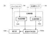
- FIG. 19 is a diagram showing functional blocks included in the portable terminal 1 c according to still another preferred embodiment, together with the flow of data.
- the portable terminal device 1 c includes a straight walking determination unit 103 c and a correction unit 104.
- the straight walking determination unit 103 c and the correction unit 104 are functional blocks implemented by the CPU 10 operating according to the program 110.
- the straight walking determination unit 103c compares the angular velocity information 140 acquired by the gyro sensor 14 and the acceleration information 150 acquired by the acceleration sensor 15 with the pattern in the walking motion given in advance, to allow the user to go straight in the walking motion It is determined whether or not.
- the straight walking determination unit 103c converts the angular velocity information 140 and the acceleration information 150 into a coordinate system (W axis, S axis and V axis) indicating the walking motion of the user, as in the walking cycle calculation unit 100 in the preferred embodiment.
- the angular velocity ⁇ w, ⁇ s, ⁇ v and the accelerations ⁇ w, ⁇ s, ⁇ v are obtained. It also has a function to calculate the walking cycle according to these values.
- the accelerations ⁇ w and ⁇ v and the angular velocity ⁇ s reflect the forward movement in walking motion.
- the angular velocity ⁇ w, ⁇ v and the acceleration ⁇ s reflect the turning motion in the walking motion.
- the accelerations ⁇ w and ⁇ v have a period of one step unit
- the angular velocity ⁇ v has a period of one multiple step unit.
- straight walk determination is made by extracting feature points in units of one or more steps for the pattern of walking motion whose walking state is known in advance and inputting it to a machine learning device (for example, a support vector machine or neural network) to learn.
- a machine learning device for example, a support vector machine or neural network
- the function of the unit 103c can be realized. That is, also in another preferred embodiment, the walking cycle is one multiple walking cycle.
- the pattern of the walking state to be learned is assumed to be straight, right turn, left turn, etc. Moreover, the pattern by the difference in a holding state is also assumed to the pattern of the walking state to learn. For example, a state in which the portable terminal device 1c is held in a hand (hand gesture state), a state in which the display unit 13 is viewed, a state in which it is put in a pocket or the like, a state in which a call is made, and the like are assumed.
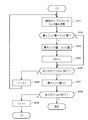
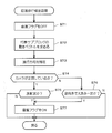
- FIG. 20 is a flow chart showing a correction process performed by the mobile terminal device 1c in still another preferred embodiment.
- the initial setting includes a process of setting Ts to a measurement timer for measuring the measurement timing by the gyro sensor 14 and the acceleration sensor 15 to start, and a process of setting an initial value of the bias value (bv) of the gyro sensor 14 And a process of determining the attitude of the mobile terminal device 1 (the attitude at the start of the process).
- a method of determining the initial attitude of the portable terminal device 1 a method in which the user operates the operation unit 12 of the portable terminal device 1c to input the attitude, a method of determining the attitude by the output of a magnetic sensor not shown, etc. Be done.
- the mobile terminal device 1c When the initial setting is completed, the mobile terminal device 1c is in a state of monitoring the measurement timer and whether one step time has elapsed (steps S101 and S105). This state is referred to as a "monitoring state" in the following description. However, in the monitoring state, the mobile terminal device 1 may execute processing other than steps S101 and S105.
- step S101 the CPU 10 determines Yes in step S101 and resets the values of the gyro sensor 14 and the acceleration sensor 15 while resetting the measurement timer to Ts (step S102). Read each one. As a result, the measurement of the angular velocity and the acceleration related to the movement of the mobile terminal device 1c is performed (step S103).
- the value of the gyro sensor 14 read out in step S103 is acquired based on the initial value of the bias value bv if the correction of the bias value bv (described later) has not been made.
- the bias value bv is corrected, it is acquired as a value corrected by the value of the corrected bias value bv. That is, the correction unit 104 corrects the angular velocity information 140 by correcting the bias value bv of the gyro sensor 14.
- the CPU 10 creates angular velocity information 140 and acceleration information 150 based on the read value of the gyro sensor 14 and the value of the acceleration sensor 15 and records the information in the storage device 11 (step S104).
- the angular velocity information 140 and the acceleration information 150 are recorded in the order of acquisition as a history, rather than being overwritten on past recordings.
- the portable terminal device 1c determines Yes in step S101 each time the value of the measurement timer becomes 0, and executes the processing of steps S102 to S104. Therefore, in the mobile terminal device 1c, the angular velocity and the acceleration are measured at each measurement cycle Ts. In addition, if step S104 is performed, the portable terminal device 1c will return to a monitoring state again.
- the straight walking determination unit 103c determines whether the walking state of the user is the straight state (step S106). In yet another preferred embodiment, the determination in step S105 is Yes each time one multistep time has elapsed. Therefore, the portable terminal device 1c (straight walk determination unit 103c) performs pattern recognition processing based on the angular velocity information 140 and the acceleration information 150 measured during that period, and the user's walking state during this period is straight ahead It is determined whether or not it was.
- step S107 the correction unit 104 corrects the bias value of the gyro sensor 14 (step S107).
- the principle of the correction unit 104 correcting the bias value of the gyro sensor 14 in step S107 is the same as step S15 in the preferred embodiment, and thus the description thereof is omitted.
- the straight walking determination unit 103c determines that the walking operation of the user is straight ahead It is preferable to record the amount of change in the traveling direction as “0” without referring to the angular velocity information 140 or the acceleration information 150 during the interval.
- step S106 if the user's walking motion is not in the straight-ahead state, the correction unit 104 skips step S107 and returns to the monitoring state. Therefore, in this case, the correction unit 104 does not correct the bias value bv of the gyro sensor 14. Therefore, when the traveling direction is recorded in order to execute the positioning process and the route recording process, the traveling direction is recorded based on the angular velocity information 140 and the acceleration information 150. However, ⁇ W may be calculated by the same calculation as step S15, and the traveling direction may be calculated by adding this.
- the portable terminal device 1c measures the angular velocity in the movement of the portable terminal device 1c to obtain the angular velocity information 140, and the acceleration in the movement of the portable terminal device 1c.
- the acceleration sensor 15 obtains acceleration information 150 by measuring the angular velocity information 140 acquired by the gyro sensor 14 and the acceleration information 150 acquired by the acceleration sensor 15 by comparing with the pattern in the walking motion given in advance.
- a correction unit 104 that corrects the angular velocity information 140 Provided.
- the straight walking determination unit 103c compares the pattern with the pattern according to the walking cycle in the walking motion of the user.
- feature points can be efficiently extracted by focusing on a walking cycle that is configured as a continuous motion and dividing it into walking cycles, and pattern recognition can be realized by a relatively short time operation. Can. Therefore, it is possible to introduce pattern recognition to the walking motion which is a continuous motion for a relatively long time, and the accuracy of detecting the straight movement state is improved. Also, it is not necessary to provide the cameras 16, 16b as in the first to further preferred embodiments.
- the walking cycle is determined in accordance with the time (one double walking time) in which the user advances the left and right legs one step at a time in the walking operation of the user.
- each step shown in the above-described preferred embodiment is merely an example, and the present invention is not limited to the order or contents shown above. That is, the order and content may be changed as appropriate, as long as the same effect is obtained.
- the functional blocks for example, the walking cycle calculation unit 100, the vector calculation unit 101, and the like
- the functional blocks are realized as software by the CPU 10 operating according to the program 110.
- some or all of these functional blocks may be configured as dedicated logic circuits and implemented as hardware.
- magnetic sensor was not used in above-described preferable embodiment, you may provide a magnetic sensor as a self-contained sensor for implement
Abstract
ユーザによって携帯される携帯端末装置に、角速度を測定して角速度情報を取得するジャイロセンサと、加速度を測定して加速度情報を取得する加速度センサと、周囲の被写体を撮像して画像情報を取得するカメラと、当該画像情報に基づいて被写体の動きベクトルを算出するベクトル演算部と、角速度情報と加速度情報とに応じて、ユーザの歩行動作による進行方向とカメラの撮像方向との相対関係を判定する相関判定部と、算出された被写体の動きベクトルと相関判定情報とに応じて、ユーザが直進状態か否かを判定する直進歩行判定部と、ユーザが直進状態であると判定されたことに応じて、ジャイロセンサにより取得される角速度情報を補正する補正部とを設ける。
Description
本発明は、観測対象物(特に歩行者)の運動に関する情報を測定するセンサを補正(較正)する技術に関する。
従来より、歩行者を目的地に誘導するためのアプリケーションが提案されている。そして、歩行者を正確に目的地に誘導するためには、歩行者の位置をリアルタイムで高精度に把握することが必要となる。歩行者の位置を測定する測位技術としては、歩行者が携帯する端末により衛星からの電波を受信するGPS(Global Positioning System)技術が一般的である。しかし、駅ビルや地下街といった屋内においては、端末が衛星からの電波を受信できないため、GPSによる測位は採用できない。このため、屋内における歩行者の誘導を実現する技術として、加速度センサや角速度センサ、あるいは磁気センサ等の自蔵センサを用いた相対的な測位技術が提案されている。自蔵センサによる相対的な測位は、例えば、歩行者の運動を自蔵センサにより検出し、進行方向と進行速度を推定し歩行者の移動ベクトルを算出することにより、実現される。
しかし、自蔵センサ(特に、ジャイロセンサ(角速度センサ))は、バイアスノイズが温度等の外乱により常に変化するため、定期的にキャリブレーションする必要がある。このような技術が、例えば、特許文献1ないし4に記載されている。特許文献1には、歩行者の動きから、当該歩行者が静止している状態を判定し、当該歩行者が静止している期間にジャイロバイアスの補正を行う技術が記載されている。また、特許文献2には、歩行者の進行方向を地図から推定して、ジャイロセンサの補正を行う技術が記載されている。また、特許文献3には、車両の進行方向をジャイロセンサから算出して、進行方向の変化量が閾値以下の場合に、当該車両の進行方向が直線であるとみなして、当該ジャイロセンサの補正を行う技術が記載されている。さらに、特許文献4には、車両から観測される白線や道路標識を基準として車両の位置を推定する技術が記載されている。
ところが、特許文献1に記載されている技術では、歩行者が静止している期間が補正に不十分だった場合や、静止状態の検出に失敗したときには、誤った値で測位を始めることになるという問題があった。
また、歩行者は常に地図上の道や車線に沿って歩行するわけではなく、人を避けたり、道を横断したりといった状況がむしろ普通に発生する。したがって、特許文献2および特許文献4に記載されている技術では、地図上の進行方向が必ずしも実際の歩行者の進行方向ではないために、誤った補正がされるという問題があった。
また、歩行者の運動は、進行方向に対して常に正対しておらず、足や腕の動きに応じて比較的大きく変動する。さらに、歩行者の歩行動作における進行方向は、回転や振動、振り子運動、上下運動などの局所的で複雑な動きが合成されて、いわば巨視的に形成されている。したがって、特許文献3に記載されている技術では、巨視的に形成される歩行者の進行方向に関して、その変化量を適切に評価するための閾値を、局所的な動きを検出するジャイロセンサに適した値として決定することが難しいという問題があった。
そもそも、特許文献3および特許文献4は、動きに関して局所的に見ても巨視的に見てもあまり差のない車両のような物体に適用される技術であって、これらの技術をそのまま歩行者に適用するのは困難である。
上記の課題を解決するため、請求項1の発明は、ユーザによって携帯される携帯端末装置であって、前記携帯端末装置の移動における角速度を測定して角速度情報を取得するジャイロセンサと、前記携帯端末装置の移動における加速度を測定して加速度情報を取得する加速度センサと、前記携帯端末装置が移動している期間における周囲の被写体を撮像して画像情報を取得するカメラと、前記画像情報に基づいて前記被写体の動きベクトルを算出するベクトル演算要素と、前記ジャイロセンサにより取得された角速度情報と前記加速度センサにより取得された加速度情報とに応じて、前記ユーザの歩行動作による進行方向と前記カメラの撮像方向との相対関係を判定する相関判定要素と、前記ベクトル演算要素により算出された前記被写体の動きベクトルと前記相関判定要素により判定された前記相関関係とに応じて、前記ユーザが歩行動作における直進状態か否かを判定する直進歩行判定要素と、前記直進歩行判定要素により前記ユーザが歩行状態における直進状態であると判定されたことに応じて、前記ジャイロセンサにより取得される角速度情報を補正する補正要素とを備える。
また、請求項2の発明は、請求項1の発明に係る携帯端末装置であって、前記ベクトル演算要素は、前記画像情報をそれぞれが第1のサイズとなる複数のブロックに分割し、前記複数のブロックのそれぞれを前記第1のサイズよりも小さい第2のサイズとなる複数のサブブロックに分割し、前記複数のサブブロックごとにエッジ量を検出して、前記複数のブロックのそれぞれにおいてエッジ量が最大となるサブブロックを各ブロックの代表サブブロックとして決定し、決定した前記代表サブブロックの動きベクトルを算出することにより、前記被写体の動きベクトルを算出する。
また、請求項3の発明は、請求項2の発明に係る携帯端末装置であって、前記ベクトル演算要素は、前記代表サブブロックの動きベクトルを、前記ユーザの歩行周期単位に平均することにより、前記被写体の動きベクトルを求める。
また、請求項4の発明は、請求項2の発明に係る携帯端末装置であって、前記ベクトル演算要素は、前記ユーザの歩行周期に同期した演算タイミングで、前記代表サブブロックの動きベクトルを算出する。
また、請求項5の発明は、請求項4の発明に係る携帯端末装置であって、前記演算タイミングは、前記カメラの速度が最小のときとなるように決定される。
また、請求項6の発明は、請求項4の発明に係る携帯端末装置であって、前記演算タイミングは、前記ユーザの両足が着地しているときとなるように決定される。
また、請求項7の発明は、請求項2の発明に係る携帯端末装置であって、前記カメラは、前記ユーザの歩行周期に同期した撮像タイミングで、前記携帯端末装置が移動している期間における周囲の被写体を撮像する。
また、請求項8の発明は、請求項7の発明に係る携帯端末装置であって、前記撮像タイミングは、前記カメラの速度が最小のときとなるように決定される。
また、請求項9の発明は、請求項7の発明に係る携帯端末装置であって、前記撮像タイミングは、前記ユーザの両足が着地しているときとなるように決定される。
また、請求項10の発明は、請求項3の発明に係る携帯端末装置であって、前記歩行周期は、前記ユーザの歩行動作において、前記ユーザが左右の足をそれぞれ1歩ずつ進める時間に応じて決定されている。
また、請求項11の発明は、請求項4の発明に係る携帯端末装置であって、前記歩行周期は、前記ユーザの歩行動作において、前記ユーザが左右の足をそれぞれ1歩ずつ進める時間に応じて決定されている。
また、請求項12の発明は、請求項1の発明に係る携帯端末装置であって、前記相関関係には、前記ユーザの歩行動作による進行方向に対して前記カメラの撮像方向が正対する関係が含まれる。
また、請求項13の発明は、請求項12の発明に係る携帯端末装置であって、前記ユーザの歩行動作による進行方向に対して前記カメラの撮像方向が正対している場合において、前記直進歩行判定要素は、前記ベクトル演算要素により求められた前記被写体の動きベクトルが、画像情報において放射状となっている場合に、前記ユーザの歩行動作が直進状態であると判定する。
また、請求項14の発明は、ユーザによって携帯される携帯端末装置であって、前記携帯端末装置の移動における角速度を測定して角速度情報を取得するジャイロセンサと、前記携帯端末装置の移動における加速度を測定して加速度情報を取得する加速度センサと、前記ジャイロセンサにより取得された角速度情報および前記加速度センサにより取得された加速度情報を、予め与えられる歩行動作におけるパターンと比較することにより、前記ユーザが歩行動作における直進状態か否かを判定する直進歩行判定要素と、前記直進歩行判定要素により前記ユーザが歩行状態における直進状態であると判定されたことに応じて、前記ジャイロセンサにより取得される角速度情報を補正する補正要素とを備える。
また、請求項15の発明は、請求項14の発明に係る携帯端末装置であって、前記直進歩行判定要素は、前記ユーザの歩行動作における歩行周期に応じて、前記パターンとの比較を行う。
また、請求項16の発明は、請求項15の発明に係る携帯端末装置であって、前記歩行周期は、前記ユーザの歩行動作において、前記ユーザが左右の足をそれぞれ1歩ずつ進める時間に応じて決定されている。
また、請求項17の発明は、コンピュータ読み取りが可能なプログラムを記録する記録媒体であって、前記プログラムは、コンピュータにより実行されることにより、前記コンピュータに、前記コンピュータの移動における角速度をジャイロセンサにより測定して角速度情報を取得する工程と、前記コンピュータの移動における加速度を加速度センサにより測定して加速度情報を取得する工程と、前記コンピュータが移動している期間における周囲の被写体をカメラにより撮像して画像情報を取得する工程と、前記カメラにより取得された前記画像情報に基づいて前記被写体の動きベクトルを算出する工程と、前記ジャイロセンサにより取得された角速度情報と前記加速度センサにより取得された加速度情報とに応じて、前記ユーザの歩行動作による進行方向と前記カメラの撮像方向との相対関係を判定する工程と、算出された前記被写体の動きベクトルと前記相関関係とに応じて、前記ユーザが歩行動作における直進状態か否かを判定する工程と、前記ユーザが歩行状態における直進状態であると判定されたことに応じて、前記ジャイロセンサにより取得される角速度情報を補正する工程とを有する補正方法を実行させる。
また、請求項18の発明は、コンピュータ読み取りが可能なプログラムを記録する記録媒体であって、前記プログラムは、コンピュータにより実行されることにより、前記コンピュータに、前記コンピュータの移動における角速度をジャイロセンサにより測定して角速度情報を取得する工程と、前記コンピュータの移動における加速度を加速度センサにより測定して加速度情報を取得する工程と、前記ジャイロセンサにより取得された角速度情報および前記加速度センサにより取得された加速度情報を、予め与えられる歩行動作におけるパターンと比較することにより、前記ユーザが歩行動作における直進状態か否かを判定する工程と、前記ユーザが歩行状態における直進状態であると判定されたことに応じて、前記ジャイロセンサにより取得される角速度情報を補正する工程とを有する補正方法を実行させる。
また、請求項19の発明は、補正方法であって、携帯端末装置の移動における角速度をジャイロセンサにより測定して角速度情報を取得する工程と、前記携帯端末装置の移動における加速度を加速度センサにより測定して加速度情報を取得する工程と、前記携帯端末装置が移動している期間における周囲の被写体をカメラにより撮像して画像情報を取得する工程と、前記カメラにより取得された前記画像情報に基づいて前記被写体の動きベクトルを算出する工程と、前記ジャイロセンサにより取得された角速度情報と前記加速度センサにより取得された加速度情報とに応じて、前記ユーザの歩行動作による進行方向と前記カメラの撮像方向との相対関係を判定する工程と、算出された前記被写体の動きベクトルと前記相関関係とに応じて、前記ユーザが歩行動作における直進状態か否かを判定する工程と、前記ユーザが歩行状態における直進状態であると判定されたことに応じて、前記ジャイロセンサにより取得される角速度情報を補正する工程とを有する。
また、請求項20の発明は、補正方法であって、携帯端末装置を所持したユーザの既知の歩行動作におけるパターンの特徴点を学習させる工程と、携帯端末装置の移動における角速度をジャイロセンサにより測定して角速度情報を取得する工程と、前記携帯端末装置の移動における加速度を加速度センサにより測定して加速度情報を取得する工程と、前記ジャイロセンサにより取得された角速度情報および前記加速度センサにより取得された加速度情報を、前記パターンの特徴点と比較することにより、前記ユーザが歩行動作における直進状態か否かを判定する工程と、前記ユーザが歩行状態における直進状態であると判定されたことに応じて、前記ジャイロセンサにより取得される角速度情報を補正する工程とを有する。
請求項1ないし13、請求項17および請求項19に記載の発明は、画像情報に基づいて被写体の動きベクトルを算出し、ジャイロセンサにより取得された角速度情報と加速度センサにより取得された加速度情報とに応じて、ユーザの歩行動作による進行方向とカメラの撮像方向との相対関係を判定し、算出された被写体の動きベクトルと当該相関関係とに応じて、ユーザが歩行動作における直進状態か否かを判定することにより、ユーザが歩行動作における直進状態であるか否かを精度よく判定することができる。
また、請求項14ないし16、請求項18および請求項20に記載の発明は、ジャイロセンサにより取得された角速度情報および加速度センサにより取得された加速度情報を、予め与えられる歩行動作におけるパターンと比較することにより、ユーザが歩行動作における直進状態か否かを判定することにより、ユーザが歩行動作における直進状態であるか否かを精度よく判定することができるとともに、カメラを設ける必要がない。
1,1a,1b,1c 携帯端末装置
10 CPU
100,100a,100b 歩行周期演算部
101,101a,101b ベクトル演算部
102 相関判定部
103,103c 直進歩行判定部
104 補正部
11 記憶装置
110 プログラム
111 動きベクトル情報
112 相関判定情報
12 操作部
13 表示部
14 ジャイロセンサ
140 角速度情報
15 加速度センサ
150 加速度情報
16,16b カメラ
160 画像情報
161,162,163,164 ブロック
161a サブブロック
10 CPU
100,100a,100b 歩行周期演算部
101,101a,101b ベクトル演算部
102 相関判定部
103,103c 直進歩行判定部
104 補正部
11 記憶装置
110 プログラム
111 動きベクトル情報
112 相関判定情報
12 操作部
13 表示部
14 ジャイロセンサ
140 角速度情報
15 加速度センサ
150 加速度情報
16,16b カメラ
160 画像情報
161,162,163,164 ブロック
161a サブブロック
以下、本発明の好適な実施の形態について、添付の図面を参照しつつ、詳細に説明する。ただし、以下の説明において特に断らない限り、方向や向きに関する記述は、当該説明の便宜上、図面に対応するものであり、例えば実施品、製品または権利範囲等を限定するものではない。
また、本出願では、2013年3月29日に日本国に出願された特許出願番号2013-072311の利益を主張し、当該出願の内容は引用することによりここに組み込まれているものとする。
図1は、好ましい実施の形態における携帯端末装置1を示す図である。携帯端末装置1は、操作部12および表示部13を備えており、ユーザによって携帯される装置として構成されている。
以下の説明において、歩行者であるユーザの歩行動作は、当該ユーザが歩いているのか、走っているのかを区別しないものとする。また、歩行動作における「1歩」とは、人が片足を上げ始めてから、その足を前に出し、その足が地面に着き、次の足を上げ始めるまでの動作とする。また、「1複歩」とは、左右1歩ずつの動作を含む動作とする。さらに、「1複歩時間」とは、1複歩にかかる時間とする。
操作部12は、携帯端末装置1に対してユーザが指示を与えるために操作されるハードウェアである。操作部12としては、例えば、各種ボタン類やキー、回転セレクタ、タッチパネルなどが該当する。
表示部13は、ユーザに対して各種情報を表示することにより、情報を提供する機能を有するハードウェアである。表示部13としては、例えば、ランプやLED、液晶パネル、液晶ディスプレイ、有機ELディスプレイなどが該当する。
図2は、好ましい実施の形態における携帯端末装置1のブロック図である。携帯端末装置1は、すでに説明した操作部12および表示部13の他に、CPU10、記憶装置11、ジャイロセンサ14、加速度センサ15およびカメラ16を備えている。
CPU10は、記憶装置11に格納されているプログラム110を読み取りつつ実行し、各種データの演算や制御信号の生成等を行う。これにより、CPU10は、携帯端末装置1が備える各構成を制御するとともに、各種データを演算し作成する機能を有している。すなわち、携帯端末装置1は、一般的なコンピュータとして構成されている。
記憶装置11は、携帯端末装置1において各種データを記憶する機能を提供する。言い換えれば、記憶装置11が携帯端末装置1において電子的に固定された情報を保存する。特に、好ましい実施の形態における記憶装置11は、プログラム110を記憶するために使用される。
記憶装置11としては、CPU10の一時的なワーキングエリアとして使用されるRAMやバッファ、読み取り専用のROM、不揮発性のメモリ(例えばNANDメモリなど)、比較的大容量のデータを記憶するハードディスク、専用の読み取り装置に装着された可搬性の記憶媒体(PCカード、SDカード、USBメモリなど)等が該当する。図2においては、あたかも記憶装置11が1つの構造物であるかのように図示している。しかし、通常、記憶装置11は、上記例示した各種装置(あるいは媒体)のうち、必要に応じて採用される複数種類の装置から構成されるものである。すなわち、好ましい実施の形態において、記憶装置11は、データを記憶する機能を有する装置群の総称である。
また、現実のCPU10は高速にアクセス可能なRAMを内部に備えた電子回路である。しかし、このようなCPU10が備える記憶装置も、説明の都合上、記憶装置11に含めて説明する。すなわち、好ましい実施の形態においては、一時的にCPU10自体が記憶するデータも、記憶装置11が記憶するとして説明する。
ジャイロセンサ14は、携帯端末装置1の移動における角速度を測定して角速度情報140(図3参照)を取得する。以下の説明では、ジャイロセンサ14が角速度情報140を取得する周期(サンプリング周期)を、「Ts」と称する。
加速度センサ15は、携帯端末装置1の移動における加速度を測定して加速度情報150(図3参照)を取得する。
詳細は図示しないが、カメラ16は、レンズやミラーなどの光学素子と、CCDなどの光電変換素子とを備えており、一般的なデジタルカメラとして構成されている。カメラ16は、少なくとも携帯端末装置1が移動している期間における周囲の被写体を撮像して画像情報160(図3参照)を取得する。
カメラ16は、CPU10からの制御信号に応じて、所定の撮像タイミングで撮像するように構成されている。好ましい実施の形態におけるカメラ16は、撮像周期「Tc」で撮像を行い、新たな画像情報160を取得するものとする。
図3は、好ましい実施の形態における携帯端末装置1が備える機能ブロックをデータの流れとともに示す図である。図に示す歩行周期演算部100、ベクトル演算部101、相関判定部102、直進歩行判定部103および補正部104は、CPU10がプログラム110に従って動作することにより実現される機能ブロックである。
歩行周期演算部100は、角速度情報140および加速度情報150を参照して、ユーザ(歩行者)の歩行動作における歩行周期を決定する。歩行周期演算部100は、決定した歩行周期をベクトル演算部101および補正部104に伝達する。また、詳細は後述するが、歩行周期演算部100は、ユーザの進行方向を相関判定部102に伝達する機能も有している。
ベクトル演算部101は、画像情報160に基づいて、画像情報160における被写体の動きベクトルを算出し、動きベクトル情報111を作成する機能を有している。ベクトル演算部101が動きベクトルを演算する間隔を、以下、演算間隔「Tv」と称する。動きベクトルは、演算間隔Tvをおいて撮像された2枚の静止画像(画像情報160)を比較して演算される。したがって、演算間隔は、撮像間隔の整数倍となり、Tv=n×Tc(nは自然数。)である。
なお、ここにいう「画像情報160における被写体の動きベクトル」とは、厳密に言えば、ユーザの動作に従って携帯端末装置1が動くことによって生じる見かけ上の被写体の動きによる動きベクトルと、被写体自体の動きによって生じる動きベクトルとの合成である。しかし、以下の説明では、被写体は静止しているものとして扱い、被写体自体の動きによって生じる動きベクトルは無視するものとする。また、好ましい実施の形態におけるベクトル演算部101は、歩行周期演算部100から伝達された歩行周期を、動きベクトル情報111に含めるものとする。
相関判定部102は、ジャイロセンサ14により取得された角速度情報140と、加速度センサ15により取得された加速度情報150とに応じて、ユーザの歩行動作による進行方向とカメラ16の撮像方向との相対関係を判定する。ただし、詳細は後述するが、好ましい実施の形態における相関判定部102は、角速度情報140と加速度情報150とに基づいて歩行周期演算部100が歩行周期を演算する過程において求まる進行方向を利用する。
相関判定部102による判定結果は、相関判定情報112として記憶される。
直進歩行判定部103は、ベクトル演算部101により算出された動きベクトル情報111と相関判定部102により判定された相関関係(相関判定情報112)とに応じて、ユーザが歩行動作における直進状態か否かを判定する。
補正部104は、直進歩行判定部103によりユーザが歩行状態における直進状態であると判定されたことに応じて、ジャイロセンサ14のバイアス値(bv)を補正する機能を有している。また、補正部104は、すでに取得されている角速度情報140を過去に遡って補正する機能も有している。
以上が、好ましい実施の形態における携帯端末装置1の構成および機能の説明である。次に、携帯端末装置1において、ジャイロセンサ14による測定値である角速度情報140を補正する補正方法について説明する。
図4は、好ましい実施の形態におけるジャイロセンサ14に対する補正処理を示す流れ図である。
なお、携帯端末装置1では、図4に示す処理と並行して、あるいは、一部の処理を共有して、他の処理が行われていてもよい。他の処理とは、例えば、ユーザの位置を特定する測位処理や測位処理の結果を用いた行き先案内処理、経路記録処理などである。
また、図4に示す処理が開始されるまでに、携帯端末装置1では、所定の初期設定が実行されているものとする。初期設定には、ジャイロセンサ14および加速度センサ15による測定タイミングを計測するための測定タイマにTsをセットして起動する処理と、カメラ16による撮像タイミングを計測するための撮像タイマにTcをセットして起動する処理とが含まれるが、演算タイマは起動されない。動きベクトルを演算する処理は、少なくとも1枚の画像情報160が取得され、後述する代表サブブロックが決定されてからでなければ実行できないからである。
また、初期設定には、ジャイロセンサ14のバイアス値(bv)の初期値を設定する処理と、携帯端末装置1の姿勢(処理開始時の姿勢)を決定する処理とが含まれる。携帯端末装置1の初期姿勢を決定する手法としては、ユーザが携帯端末装置1の操作部12を操作して姿勢を入力する方法や、図示しない磁気センサの出力により姿勢を決定する方法などが想定される。
初期設定が終了すると、携帯端末装置1は、測定タイマと、撮像タイマと、演算タイマとを監視する状態となる(ステップS1,S5,S11)。この状態を、以下の説明では、「監視状態」と称する。ただし、監視状態において、携帯端末装置1は、ステップS1,S5,S11以外の他の処理を実行していてもよい。
監視状態において、測定タイマが0となり、測定タイミングが到来すると、CPU10は、ステップS1においてYesと判定し、測定タイマをTsにリセットしつつ(ステップS2)、ジャイロセンサ14および加速度センサ15の値をそれぞれ読み出す。これによって、携帯端末装置1の動きに関する角速度および加速度の測定が実行される(ステップS3)。
なお、ステップS3において読み出されるジャイロセンサ14の値は、未だバイアス値bvの補正(後述)がされていなければ、バイアス値bvの初期値に基づいて取得される。一方で、バイアス値bvの補正がされた後は、補正後のバイアス値bvの値により補正された値として取得される。
次に、CPU10は、読み出したジャイロセンサ14の値および加速度センサ15の値とに基づいて、角速度情報140および加速度情報150を作成し、記憶装置11に記録する(ステップS4)。なお、好ましい実施の形態では、角速度情報140および加速度情報150は、過去の記録に上書きされるのではなく、履歴として取得順に記録されていくものとする。
このように、携帯端末装置1は、測定タイマの値が0となるごとに、ステップS1においてYesと判定し、ステップS2ないしS4の処理を実行する。したがって、携帯端末装置1では、測定周期Tsごとに角速度および加速度が測定される。なお、ステップS4を実行すると、携帯端末装置1は、再度、監視状態に戻る。
監視状態において、撮像タイマが0となり、撮像タイミングが到来すると、CPU10は、ステップS5においてYesと判定し、撮像タイマをTcにリセットしつつ(ステップS6)、周囲の被写体を撮像するようにカメラ16を制御する。これにより、カメラ16が撮像を行い(ステップS7)、画像情報160が作成され、記憶装置11に記録される。なお、ステップS7の処理においては、画像情報160の削除または上書きはされないものとする。すなわち、画像情報160は撮像順に記録されていくものとする。
撮像が実行され、新たな画像情報160が記録されると、CPU10は、演算タイミングを計測するための演算タイマが起動されているか否かを判定する(ステップS8)。演算タイマが起動されていない場合は、CPU10は演算タイマにTvをセットして起動し(ステップS9)、代表サブブロック決定処理を実行する(ステップS10)。一方、すでに演算タイマが起動されている場合は、ステップS9,S10をスキップして、監視状態に戻る。
図5および図6は、好ましい実施の形態における代表サブブロック決定処理を示す流れ図である。
代表サブブロック決定処理が開始されると、まず、ベクトル演算部101は、最新の画像情報160を取得して、複数のブロックに分割する(ステップS21)。
図7は、ベクトル演算部101による画像情報160の分割の様子を示す図である。図7では、両側に商品陳列用の棚が配置された通路をユーザが進んでいるときに撮像される周囲の被写体(画像情報160)を例に示している。
ステップS21において、ベクトル演算部101は、画像情報160をそれぞれが第1のサイズとなる複数のブロックに分割する。各ブロックは、画像情報160の部分画像に相当する。図7に示す例では、画像情報160は、ブロック161,162,163,164の4つのブロックに分割されている。
次に、ベクトル演算部101は、ブロックカウンタiの値を「1」にリセットする(ステップS22)。ブロックカウンタiとは、処理中のブロックを識別するためのカウンタである。図7に示すように、好ましい実施の形態におけるベクトル演算部101は、画像情報160を4つのブロックに分割するので、ブロックカウンタiの値は、「1」ないし「4」の整数である。
次に、ベクトル演算部101は、ブロックカウンタiに示されるi番目のブロックを、さらにサブブロックに分割する(ステップS23)。
図8は、図7に示すブロック161をベクトル演算部101が分割する様子を示す図である。なお、図8では、図7に示すブロック161を拡大して図示している。
ステップS23において、ベクトル演算部101は、i番目のブロックを第1のサイズよりも小さい第2のサイズとなる複数のサブブロックに分割する。各サブブロックは、画像情報160の部分画像に相当する。図8に示す例では、ブロック161は54個のサブブロックに分割されている。
ステップS23を実行すると、ベクトル演算部101は、最大エッジ量の値を「0」にリセットするとともに、サブブロックカウンタjの値を「1」にリセットする(ステップS24)。最大エッジ量とは、処理中のブロックに含まれるサブブロックの最大エッジ量を一時的に格納しておく変数である。また、サブブロックカウンタjとは、処理中のサブブロックを識別するためのカウンタである。図8に示すように、ベクトル演算部101は、1個のブロックを54個のサブブロックに分割するので、サブブロックカウンタjの値は、「1」ないし「54」の整数である。
次に、ベクトル演算部101は、ステップS23において分割した複数のサブブロックのうち、サブブロックカウンタjに示されるj番目のサブブロックのエッジ量を演算し(ステップS31)、求めたj番目のサブブロックのエッジ量が最大エッジ量より大きいか否かを判定する(ステップS32)。
ステップS32においてYesの場合、ベクトル演算部101は、j番目のエッジ量の値を新たに最大エッジ量とし(ステップS33)、i番目のブロックにおける代表サブブロックを識別するための識別子SBiに、「j」をセットする(ステップS34)。すなわち、1番目からj-1番目までのサブブロックのエッジ量よりも、j番目のサブブロックのエッジ量の方が大きい場合には、j番目のサブブロックのエッジ量が最大エッジ量として格納され、識別子SBiに「j」が格納される。
一方、ステップS32においてNoの場合、ベクトル演算部101は、j番目のサブブロックを代表サブブロックに決定することはないので、ステップS33,S34の処理をスキップする。
次に、ベクトル演算部101は、i番目のブロックについて全てのサブブロックに関するエッジ量の演算と評価が終了したか否かを判定する(ステップS35)。好ましい実施の形態において、i番目のブロックにおけるサブブロックの数は54個であるから、例えば、ステップS35においてj≧54か否かを判定すればよい。
ステップS35においてNoの場合(未だ全てのサブブロックについて終了していない場合)、ベクトル演算部101は、jの値をインクリメントし(ステップS36)、ステップS31からの処理を繰り返す。すなわち、i番目のブロックの次のサブブロックについての処理を継続する。
一方、ステップS35においてYesの場合(全てのサブブロックについて終了している場合)、ベクトル演算部101は、最大エッジ量の値を「0」にリセットし(ステップS37)、i番目のブロックについての処理を終了する。すなわち、i番目のブロックの代表サブブロックを識別子SBiによって示されるサブブロックに決定する。
次に、ベクトル演算部101は、全てのブロックについて代表サブブロックの決定が終了したか否かを判定する(ステップS38)。好ましい実施の形態において、ブロックの数は4個であるから、例えば、ステップS38においてi≧4か否かを判定すればよい。
ステップS38においてNoの場合(未だ全てのブロックについて終了していない場合)、ベクトル演算部101は、iの値をインクリメントし(ステップS39)、ステップS23からの処理を繰り返す。すなわち、次のブロックについての処理を継続する。
ステップS38においてYesの場合(全てのブロックについて終了している場合)、ベクトル演算部101は、代表サブブロック決定処理を終了し、図4の処理に戻る。
このようにして、ベクトル演算部101は、複数のサブブロックごとにエッジ量を検出して、複数のブロックのそれぞれにおいてエッジ量が最大となるサブブロックを各ブロックの代表サブブロックとして決定する。図8に示す例では、陳列棚の角部が含まれるサブブロック161aがブロック161の中の代表サブブロックとして決定されている。なお、図8には図示していないが、ブロック162,163,164の中からも、エッジ量が最大のサブブロックが、それぞれ代表サブブロックとして決定される。
携帯端末装置1は、代表サブブロックの動きベクトルに基づいて、携帯端末装置1の動きを検出しようとするものである。そして、動きベクトルを算出するには、画像におけるエッジ量が多い部分(サブブロック)を抽出して算出することが好ましい。
好ましい実施の形態におけるベクトル演算部101は、先述のように、各ブロックにおける代表サブブロックを、当該ブロック内においてエッジ量が最大となるサブブロックに決定する。したがって、動きベクトルを精度よく算出することができる。
一方で、算出された動きベクトルによって携帯端末装置1の動き(ユーザの動き)を推定するためには、算出される動きベクトルの画像情報160における位置が分散している方が好ましい。すなわち、代表サブブロックが画像情報160内の様々な位置から選択されていることが好ましい。
好ましい実施の形態におけるベクトル演算部101は、先述のように、画像情報160における1枚の静止画像を、一旦、4つのブロックに分割し、各ブロックの中からそれぞれ代表サブブロックを決定することにより、動きベクトルの算出対象となるサブブロックが、画像情報160内において局在することを抑制することができる。したがって、後述する処理において、ユーザの進行方向が直進状態か否かを正確に判定することができる。
図4に戻って、監視状態において、演算タイマが0となり、演算タイミングが到来すると、CPU10は、ステップS11においてYesと判定し、演算タイマをTvにリセットしつつ(ステップS12)、直進歩行検出処理を実行する(ステップS13)。
図9は、好ましい実施の形態における直進歩行検出処理を示す流れ図である。
直進歩行検出処理が開始されると、直進歩行判定部103は、ユーザの歩行動作が直進歩行か否かを示す直進フラグをOFFにリセットする(ステップS41)。
次に、ベクトル演算部101が、最新の画像情報160における各代表サブブロックの位置を特定して、代表サブブロックを決定してから(代表サブブロックを決定した画像情報160が撮像されてから)当該最新の画像情報160が撮像されるまでの期間のそれぞれの代表サブブロックの動きベクトルを求める(ステップS42)。
なお、代表サブブロックを決定してから最新の画像情報160が撮像されるまでの期間は、演算タイマで管理されており、演算周期Tvである。すなわち、ステップS42では、Tvの間の動きベクトルが算出される。ただし、演算周期Tvに対して、撮像周期Tcが離散的であると見なせる場合、当該期間は、n×Tc(ただしn×Tc≦Tv<(n+1)×Tc)である。
次に、歩行周期演算部100が、ユーザの歩行動作における歩行周期を求める。
図10は、ジャイロセンサ14、加速度センサ15およびカメラ16の座標系を示す図である。携帯端末装置1において、ジャイロセンサ14、加速度センサ15およびカメラ16はいずれも固定されている。したがって、携帯端末装置1の姿勢が変化したとしても、ジャイロセンサ14、加速度センサ15およびカメラ16の相対的な位置関係は変化しない。
図10に示すように、好ましい実施の形態における携帯端末装置1において、カメラ16の撮像方向をX軸とする。3軸の加速度センサ15の軸のうちの1つをX軸に一致させるように加速度センサ15を配置するとともに、他の2軸をそれぞれY軸とZ軸とする。これにより、加速度センサ15の出力は、X軸方向の加速度αxと、Y軸方向の加速度αyと、Z軸方向の加速度αzとなる。
次に、3軸回りの角速度を測定するジャイロセンサ14の3軸をそれぞれ、X軸、Y軸、Z軸に一致させるようにジャイロセンサ14を配置する。これにより、ジャイロセンサ14の出力は、X軸回りの角速度ωxと、Y軸回りの角速度ωyと、Z軸回りの角速度ωzとなる。
なお、このように配置することができなくても、ジャイロセンサ14、加速度センサ15およびカメラ16の相対的な位置関係(既知)は変化しないので、ジャイロセンサ14および加速度センサ15の出力値を既知の位置関係に基づいてX軸、Y軸およびZ軸のそれぞれに対応した値に変換することができる。
図11は、ユーザの歩行動作における座標系を示す図である。図11に示すように、重力と逆向き方向をV軸、ユーザの進行方向をW軸とする。ここで、ユーザの進行方向は水平面内に定義し、V軸とW軸とは互いに垂直であるものとする。さらに、W軸およびV軸と垂直となる軸をS軸とする。
まず、歩行周期演算部100は、従来のカルマンフィルタを用いて加速度情報150に基づいて重力方向ベクトルを推定する。このようにして推定された重力方向ベクトルの逆向き方向として、V軸が決定される。
V軸が決まると、歩行周期演算部100は、V軸にZ軸を合わせるように回転させ、このときの回転角θ1を取得する。次に、V軸にZ軸を合わせた状態(Z軸をθ1だけ回転させた状態)で、当該Z軸回りに360°回転させつつ、αyおよびαzを演算する。一般に、人の歩行動作においては、W軸方向(進行方向)の加速度が大きく、S軸方向(進行方向に対する左右方向)の加速度が小さいという特性がある。したがって、当該Z軸を360°回転させた中で、αzが最大でαyが最小となる回転角θ2を決定し、このときのX軸およびY軸をそれぞれW軸およびS軸と決定する。
このようにして求めた回転角θ1,θ2を用いることにより、歩行周期演算部100は、XYZ座標系の出力値を、WSV座標系に変換することができる。すなわち、加速度αx,αy,αzから、W軸方向の加速度αw、S軸方向の加速度αsおよびV軸方向の加速度αvを求めることができる。同様に、角速度ωx,ωy,ωzから、W軸回りの角速度ωw、S軸回りの角速度ωsおよびV軸回りの角速度ωvを求めることができる。
図12は、人の歩行動作における加速度αv,αwおよび角速度ωvとを例示する図である。
図12から明らかなように、加速度αv,αwは1歩周期であるが、角速度ωvは1複歩周期である。したがって、歩行動作の周期としては、1複歩周期を採用することが適切といえる。
また、角速度ωvは比較的複雑に変化するため、歩行周期を決定するためには、加速度αvまたは加速度αwを用いた方がよいこともわかる。例えば、加速度αwが極小値をとってから、さらに極小値を2回とるまでの期間が1複歩時間であり、歩行周期である。
このように、ステップS43において、歩行周期演算部100は、角速度情報140および加速度情報150に基づいて、歩行周期を決定する。なお、極小値の検出は、例えば、ゼロ交差法を採用することができる。
歩行周期が求まると、歩行周期演算部100は、求めた歩行周期をベクトル演算部101に伝達する。そして、ベクトル演算部101が、ステップS42で求めた動きベクトルを、歩行周期単位に平均をとり(ステップS44)、被写体の動きベクトルとする。このようにして、ベクトル演算部101が、被写体の動きベクトルを求めることにより、進行方向への動き以外の動きによる影響を抑制することができる。
次に、相関判定部102がユーザの進行方向を求める(ステップS45)。好ましい実施の形態において、進行方向は、ステップS43が実行された時点で、歩行周期演算部100によりW軸方向として決定されている。したがって、好ましい実施の形態における相関判定部102は、ステップS45において、改めて角速度情報140および加速度情報150から進行方向を求めることはせず、歩行周期演算部100から伝達されたW軸方向を用いる。
ステップS45が実行されると、相関判定部102は、X軸(カメラ16の向き)とW軸(進行方向)との関係から、カメラ16が進行方向に対して正対しているか否かを判定し(ステップS46)、判定結果を相関判定情報112として記憶装置11に格納する。相関判定情報112は、直進歩行判定部103によって参照される。
ステップS46においてYesと判定された場合、直進歩行判定部103は、ステップS44においてベクトル演算部101によって求められた被写体の動きベクトルが、画像情報160の中央付近から放射状になっているか否かを判定する(ステップS47)。そして、放射状になっている場合(ステップS47においてYes。)、ユーザの歩行動作が直進状態であると判定し、直進フラグをONにセット(ステップS49)してから直進歩行検出処理を終了する。放射状になっていない場合(ステップS47においてNo。)、ユーザの歩行動作は直進状態でないと判定し、直進フラグをOFFのまま維持して直進歩行検出処理を終了する。
一方、ステップS46においてNoと判定された場合、直進歩行判定部103は、ステップS44においてベクトル演算部101によって求められた被写体の動きベクトルが、進行方向と逆向きになっており、かつ、歩行動作に変化がない期間において大きさがほぼ一定であるか否かを判定する(ステップS48)。そして、ステップS48においてYesの場合、直進歩行判定部103は、ユーザの歩行動作が直進状態であると判定し、直進フラグをONにセット(ステップS49)してから直進歩行検出処理を終了する。ステップS48においてNoの場合、直進歩行判定部103は、ユーザの歩行動作は直進状態でないと判定し、直進フラグをOFFのまま維持して直進歩行検出処理を終了する。
これにより、直進歩行検出処理が終了するときには、ユーザの歩行動作が直進状態であるか否かが検出されて、直進フラグの状態として格納される。
図4に戻って、直進歩行検出処理が終了すると、直進歩行判定部103は、直進フラグの状態を補正部104に伝達する。そして、これにより補正部104が、ユーザの歩行状態が直進状態か否かを判定する(ステップS14)。
直進状態の場合(ステップS14においてYes。)、補正部104は、ジャイロセンサ14のバイアス値を補正する(ステップS15)。
ステップS15において、補正部104がジャイロセンサ14のバイアス値を補正する原理を説明する。なお、歩行者であるユーザを測位する場合において、ユーザのW軸回りおよびS軸回りの角速度ωw,ωsを考慮する必要性は乏しい。したがって、ここでは、V軸回りの角速度ωv(進行方向に影響する。)を補正する例について説明する。
図12に示したように、進行方向を決定する基となる角速度ωvは、1複歩周期である。したがって、補正部104は、まず、1複歩あたりの進行方向の変化量(ΔW)を求める。ΔWは、1複歩時間(すなわち歩行周期)のωvの積分値として、ΔW=Σ(ωv-bv)で求めることができる。
次に、補正部104は、測定周期Tsあたりのωvの平均値ωv(ave)を、ωv(ave)=ΔW/(歩行周期/Ts)により求める。そして、さらに、bv+ωv(ave)を新たなバイアス値bvとしてバイアス値bvを更新し補正する。
このようにして、ユーザの歩行動作が直進状態であった場合には(ステップS14においてYes。)、ステップS15が実行されて、ジャイロセンサ14のバイアス値bvが補正部104により補正される。したがって、以後、ジャイロセンサ14から出力される角速度情報140が補正される。
なお、測位処理や経路記録処理を実行するために進行方向を記録している場合には、直進歩行判定部103によってユーザの歩行動作が直進状態であると判定されている間は、角速度情報140や加速度情報150を参照せずに、進行方向の変化量を「0」として記録することが好ましい。
一方、ステップS14においてNoの場合(ユーザの歩行動作が直進状態でない場合)、補正部104は、ステップS15をスキップし、ジャイロセンサ14のバイアス値bvの補正は行わない。したがって、測位処理や経路記録処理を実行するために進行方向を記録している場合には、角速度情報140や加速度情報150に基づいて進行方向を記録することになる。ただし、ステップS15と同様の演算により、ΔWを求め、これを加算することにより進行方向を演算してもよい。
ステップS14においてNoと判定されるか、あるいは、ステップS15が実行されると、ベクトル演算部101は、新たな代表サブブロックを決定するために、代表サブブロック決定処理を実行する(ステップS16)。なお、ステップS16における代表サブブロック決定処理は、ステップS10と同様に実行可能であるため、説明は省略する。
ステップS16を実行すると、携帯端末装置1は、再び、監視状態に戻る。
以上のように、好ましい実施の形態における携帯端末装置1は、携帯端末装置1の移動における角速度を測定して角速度情報140を取得するジャイロセンサ14と、携帯端末装置1の移動における加速度を測定して加速度情報150を取得する加速度センサ15と、携帯端末装置1が移動している期間における周囲の被写体を撮像して画像情報160を取得するカメラ16と、画像情報160に基づいて被写体の動きベクトル情報111を算出するベクトル演算部101と、ジャイロセンサ14により取得された角速度情報140と加速度センサ15により取得された加速度情報150とに応じて、ユーザの歩行動作による進行方向とカメラの撮像方向との相対関係を判定する相関判定部102と、ベクトル演算部101により算出された被写体の動きベクトル情報111と相関判定部102により判定された相関関係とに応じて、ユーザが歩行動作における直進状態か否かを判定する直進歩行判定部103と、直進歩行判定部103によりユーザが歩行状態における直進状態であると判定されたことに応じて、ジャイロセンサ14により取得される角速度情報140を補正する補正部104とを備える。これにより、ユーザが歩行動作における直進状態であるか否かを精度よく判定することができる。したがって、ジャイロセンサ14の補正を精度よく実現することができる。
また、ベクトル演算部101は、画像情報160をそれぞれが第1のサイズとなる複数のブロックに分割し、複数のブロックのそれぞれを第1のサイズよりも小さい第2のサイズとなる複数のサブブロックに分割し、複数のサブブロックごとにエッジ量を検出して、複数のブロックのそれぞれにおいてエッジ量が最大となるサブブロックを各ブロックの代表サブブロックとして決定し、決定した代表サブブロックの動きベクトルを算出することにより、被写体の動きベクトル情報111を算出する。これにより、動きベクトル情報111の算出対象となるサブブロックが、画像情報内において局在することを抑制することができる。したがって、歩行者の進行方向が直進状態か否かを正確に判定できる。
また、ベクトル演算部101は、代表サブブロックの動きベクトルを、ユーザの歩行周期単位に平均することによって被写体の動きベクトル情報111を求める。したがって、進行方向への動き以外の動きによる影響を抑制できる。
また、ユーザの歩行動作において、当該ユーザが左右の足をそれぞれ1歩ずつ進める時間(1複歩時間)に応じて歩行周期が決定されていることにより、V軸回りの角速度ωvの周期単位で処理することができ、精度が向上する。
相関判定部102によって判定する相関関係には、ユーザの歩行動作による進行方向に対してカメラ16の撮像方向が正対する関係が含まれることにより、直進状態を容易に判定できる。
ユーザの歩行動作による進行方向に対してカメラ16の撮像方向が正対している場合において、直進歩行判定部103は、ベクトル演算部101により求められた被写体の動きベクトルが、画像情報160において放射状となっている場合に、当該ユーザの歩行動作が直進状態であると判定する。これにより、効率よく、直進状態を判定することができる。
なお、各ブロックについて代表サブブロックを決定したときに、画像情報160の部分画像である各代表サブブロックのみを記録し、当該画像情報160を削除するか、あるいは、新たな画像情報160が取得されたときに上書きしてもよい。これにより、記憶しておくべき情報の容量を抑制することができる。
また、画像情報160において周辺部に位置するサブブロックが代表サブブロックに決定されると、当該代表サブブロックに相当する被写体がユーザの動きによって撮像範囲から外れてしまうことも考えられる。その場合は、動きベクトルを求めることができなくなるおそれがある。したがって、代表サブブロックを決定する場合には、画像情報160における周辺部に位置するサブブロックを候補から除外してもよい。あるいは、さらに、予測されるユーザの動き(方向や速度)に応じてどの位置のサブブロックを候補から除外するかを決定してもよい。
好ましい実施の形態における携帯端末装置1では、代表サブブロックの動きベクトルを、歩行周期で平均することにより、進行方向の動き以外の動きによる影響を抑制すると説明した。しかし、進行方向の動き以外の動きによる影響を抑制する手法はこれに限定されるものではない。
図13は、他の好ましい実施の形態における携帯端末装置1aが備える機能ブロックをデータの流れとともに示す図である。なお、他の好ましい実施の形態における携帯端末装置1aにおいて、好ましい実施の形態における携帯端末装置1と同様の構成については同符号を付し、適宜説明を省略する。
図13に示すように、携帯端末装置1aは、歩行周期演算部100の代わりに歩行周期演算部100aを備えている点と、ベクトル演算部101の代わりにベクトル演算部101aを備えている点とが、携帯端末装置1と異なっている。
歩行周期演算部100aは、歩行周期の代わりに、演算タイミングを演算してベクトル演算部101aに伝達する。
ベクトル演算部101aは、代表サブブロックの動きベクトルを、歩行周期に平均するのではなく、そのまま被写体の動きベクトルとして動きベクトル情報111を作成する。また、ベクトル演算部101aによる演算タイミングは、演算タイマによって決定されるのではなく、歩行周期演算部100から通知される。
図14は、他の好ましい実施の形態における携帯端末装置1aにより実行される補正処理を示す流れ図である。
他の好ましい実施の形態における携帯端末装置1aは、好ましい実施の形態における携帯端末装置1と同様の初期設定が実行された後、監視状態となる。また、監視状態において、携帯端末装置1aは、測定タイミングの到来と、撮像タイミングの到来と、演算タイミングの到来とを監視している(ステップS51,S55,S60)。
監視状態において、初期設定において起動された測定タイマTsが0となると、携帯端末装置1aは、ステップS51においてYesと判定し、ステップS52ないしS54の処理を実行する。なお、ステップS52ないしS54の処理は、好ましい実施の形態におけるステップS2ないしS4の処理と同様であるため、説明は省略する。
監視状態において、初期状態において起動された撮像タイマTcが0となると、携帯端末装置1aは、ステップS55においてYesと判定し、ステップS56,S57の処理を実行する。なお、ステップS56,S57の処理は、好ましい実施の形態におけるステップS6,S7の処理と同様であるため、説明は省略する。
ステップS57が実行されると、ベクトル演算部101aは、すでに代表サブブロックが決定されているか否かを判定する(ステップS58)。そして、未だ代表サブブロックが決定されていない場合には、代表サブブロック決定処理(ステップS59)を実行してから監視状態に戻る。一方、すでに代表サブブロックが決定されている場合には、ステップS59をスキップして、監視状態に戻る。なお、ステップS59における代表サブブロック決定処理は、好ましい実施の形態におけるステップS10の処理と同様であるため、説明は省略する。
なお、携帯端末装置1aでは、演算タイマTvに相当する構成は設けられておらず、演算タイマTvを起動させる処理(ステップS9に相当する処理)が実行されることはない。
監視状態において、演算タイミングが到来すると、CPU10は、ステップS60においてYesと判定する。好ましい実施の形態では、演算タイミングが到来したか否かは、演算タイマの値を参照して判定されていた。しかし、他の好ましい実施の形態では、演算タイマは設けられていないので、演算タイマの値によってステップS60の判定を実行することはできない。
これまでに説明したように、歩行動作においては、歩行周期ごとに同じ歩行状態が繰り返される。したがって、同じ状態のときに撮像された画像情報160を比較すれば、進行方向の動き以外の動きを効率的にキャンセルすることができる。すなわち、歩行周期ごとに演算タイミングが到来するように、演算タイミングを歩行周期に同期させれば、進行方向の動き以外の動きによる影響を抑制することができる。
また、画像情報160にエッジ量検出処理を行って動きベクトルを演算する場合には、当該画像情報160における手ブレが少ない方が好ましい。手ブレは、主にカメラ16が動くことによって生じ、カメラ16の動く速度が速いほど手ブレが大きくなる。したがって、携帯端末装置1aは、カメラ16の速度が最小のときに演算タイミングが到来したと判定するように構成する。これにより、カメラ16によって撮像される画像情報160において、最も手ブレが少ない状態の画像情報160によって動きベクトルを演算することができ、精度が向上する。なお、カメラ16の速度が最小となるタイミングは、加速度αw,αs,αvに基づいて、決定することができる。
以上のことから、ベクトル演算部101aは、歩行周期ごとに到来する、カメラ16の速度が最小となるタイミングで演算タイミングが到来したと判定し、ステップS60においてYesと判定する。このようなタイミングは、歩行周期演算部100aによって検出されベクトル演算部101aに伝達される。
他の好ましい実施の形態における歩行周期演算部100aは、ステップS60において、好ましい実施の形態におけるステップS43(図9)と同様にして、歩行周期を求めることができる。また、ステップS60において歩行周期を求める過程で、加速度αw,αs,αvが求まるので、これに基づいてカメラ16の速度が最小となるタイミングも決定することができ、これをベクトル演算部101aに伝達する。このようにして、他の好ましい実施の形態における携帯端末装置1aでは、演算タイミングの到来が検出される。
ステップS60においてYesと判定すると、携帯端末装置1aは、直進歩行検出処理を実行する(ステップS61)。
図15は、他の好ましい実施の形態における直進歩行検出処理を示す流れ図である。
直進歩行検出処理が開始されると、直進歩行判定部103は、直進フラグをOFFとする(ステップS71)。次に、ベクトル演算部101aが、代表サブブロックの動きベクトルを求め、動きベクトル情報111を作成し、記憶装置11に格納する(ステップS72)。
すなわち、他の好ましい実施の形態では、すでにステップS60の段階で歩行周期を求める処理が実行されているので、好ましい実施の形態におけるステップS43に相当する処理は、他の好ましい実施の形態では実行されない。
また、歩行周期に同期して代表サブブロックの動きベクトルが演算されているため、進行方向の動き以外の動きによる影響はすでにキャンセルされている。したがって、代表サブブロックの動きベクトルを歩行周期で平均する必要はなく、好ましい実施の形態おけるステップS44に相当する処理は、他の好ましい実施の形態では実行されない。そして、ステップS72において求められた代表サブブロックの動きベクトルがそのまま被写体の動きベクトルとして動きベクトル情報111に格納される。
ステップS72が実行されると、携帯端末装置1aは、ステップS73を実行する。なお、ステップS73ないしS77の処理は、好ましい実施の形態におけるステップS45ないしS49の処理と同様のため、説明は省略する。
ステップS61の直進歩行検出処理を終了すると、携帯端末装置1aは、ステップS62を実行する。なお、ステップS62が実行されてからの処理は、好ましい実施の形態におけるステップS14が実行されてからの処理と同様であるため、説明は省略する。
以上のように、他の好ましい実施の形態における携帯端末装置1aでは、ベクトル演算部101aが、ユーザの歩行周期に同期した演算タイミングで、代表サブブロックの動きベクトルを算出する。したがって、歩行周期単位に平均しなくても、進行方向への動き以外の動きによる影響を除去できる。
また、演算タイミングが、カメラ16の速度が最小のときとなるように決定される。したがって、進行方向への動き以外の動きによる影響を抑制することができるとともに、画像情報のブレも抑制することができる。
なお、演算タイミングは、ユーザの両足が着地しているときとなるように決定されてもよい。この場合は、ユーザの体が最も安定している瞬間の動きベクトルを求めることができるため、やはり進行方向への動き以外の動きによる影響を抑制することができる。ユーザの両足が着地しているタイミングは、角速度ωw,ωs,ωv、および、加速度αw,αs,αvに基づいて歩行周期演算部100aにより検出することができる。
また、演算タイミングを歩行周期に同期させる手法としては、歩行周期演算部100aによって演算された歩行周期を、好ましい実施の形態における演算タイマと同様の構成にセットし、当該演算タイマが0となるタイミングの到来をステップS60において監視することでも実現することができる。
また、他の好ましい実施の形態では、歩行周期に同期してベクトル演算が実行されるため、ベクトル演算の演算周期が比較的長くなる。これにより、代表サブブロックに含まれる被写体の画像内における移動量が大きくなり、代表サブブロックの探索エリアが広がる懸念がある。しかしながら、携帯端末装置1では、角速度ωw,ωs,ωv、および、加速度αw,αs,αvに基づいて代表サブブロックの画像内における移動量を推定することができるため、このような問題を抑制することができる。これは以下に説明するさらに他の好ましい実施の形態においても同様である。
進行方向の動き以外の動きによる影響を抑制する手法は、好ましい実施の形態および他の好ましい実施の形態に示される手法に限定されるものではない。
図16は、さらに他の好ましい実施の形態における携帯端末装置1bが備える機能ブロックをデータの流れとともに示す図である。なお、さらに他の好ましい実施の形態における携帯端末装置1bにおいて、好ましい実施の形態における携帯端末装置1と同様の構成については同符号を付し、適宜説明を省略する。
図16に示すように、携帯端末装置1bは、カメラ16の代わりにカメラ16bを備えている点と、歩行周期演算部100の代わりに歩行周期演算部100bを備えている点と、ベクトル演算部101の代わりにベクトル演算部101bを備えている点とが、携帯端末装置1と異なっている。
カメラ16bは、歩行周期演算部100bから通知される撮像タイミングに従って撮像を行い、画像情報160を取得する。
歩行周期演算部100bは、角速度情報140および加速度情報150に基づいて歩行周期を演算するとともに、歩行周期に同期したタイミングで撮像タイミングを決定し、カメラ16bに伝達する。その一方で、歩行周期演算部100bは、ベクトル演算部101bに対しては、歩行周期を伝達することはない。
ベクトル演算部101bは、演算タイマにより演算タイミングを決定するのではなく、新たな画像情報160が取得されたタイミングを演算タイミングとして、動きベクトルの演算を実行する。
図17は、さらに他の好ましい実施の形態における携帯端末装置1bによって実行される補正処理を示す流れ図である。
さらに他の好ましい実施の形態における携帯端末装置1bにおいても、好ましい実施の形態における携帯端末装置1と同様の初期設定が実行された後に監視状態となる。しかし、携帯端末装置1bにおいては、撮像タイマは設けられていないため、当該初期設定には撮像タイマを起動する処理は含まれない。また、監視状態において、携帯端末装置1bは、測定タイミングの到来と、撮像タイミングの到来とを監視している(ステップS81,S85)。
監視状態において、初期設定において起動された測定タイマTsが0となると、携帯端末装置1bは、ステップS81においてYesと判定し、ステップS82ないしS84の処理を実行する。なお、ステップS82ないしS84の処理は、好ましい実施の形態におけるステップS2ないしS4の処理と同様であるため、説明は省略する。
監視状態において、撮像タイミングになると、携帯端末装置1bは、ステップS85においてYesと判定する。好ましい実施の形態では、撮像タイミングが到来したか否かは、撮像タイマの値を参照して判定されていた。しかし、さらに他の好ましい実施の形態では、撮像タイマは設けられていないので、撮像タイマの値によってステップS85の判定を実行することはできない。
他の好ましい実施の形態においても説明したように、歩行動作においては、歩行周期ごとに同じ歩行状態が繰り返される。したがって、同じ状態のときに撮像された画像情報160を比較すれば、進行方向の動き以外の動きを効率的にキャンセルすることができる。すなわち、歩行周期ごとに撮像タイミングが到来するように、撮像タイミングを歩行周期に同期させれば、同じ状態のときに撮像された画像情報160のみを得ることができ、進行方向の動き以外の動きによる影響を抑制することができる。
また、画像情報160にエッジ量検出処理を行って動きベクトルを演算する場合には、当該画像情報160における手ブレが少ない方が好ましいことも他の好ましい実施の形態で説明したとおりである。したがって、携帯端末装置1bは、カメラ16の速度が最小のときに撮像タイミングが到来したと判定するように構成する。これにより、他の好ましい実施の形態と同様に、カメラ16によって撮像される画像情報160において、最も手ブレが少ない状態の画像情報160によって動きベクトルを演算することができ、精度が向上する。
すなわち、携帯端末装置1aは、演算タイミングを調整することによって、最適なタイミングの画像情報160を用いて動きベクトルを演算するように構成されていたが、携帯端末装置1bは、最適なタイミングの画像情報160のみを撮像するように構成されている。これによって、カメラ16による撮像回数を大幅に減らすことが可能となり、処理負荷が軽減されるとともに、消費電力も抑制される。
以上のことから、携帯端末装置1bは、歩行周期ごとに到来する、カメラ16の速度が最小となるタイミングで撮像タイミングが到来したと判定し、ステップS85においてYesと判定する。このようなタイミングは、歩行周期演算部100bによって他の好ましい実施の形態における歩行周期演算部100aと同様の手法により検出され、カメラ16bに伝達される。
ステップS85においてYesと判定されると、カメラ16bは撮像を行い、新たな画像情報160が記憶装置11に格納される(ステップS86)。
新たな画像情報160が格納されると、ベクトル演算部101bは、代表サブブロックがすでに決定済みか否かを判定し(ステップS87)、未だ代表サブブロックが決定されていない場合(ステップS87においてNo。)、代表サブブロック決定処理(ステップS91)を実行して監視状態に戻る。なお、ステップS91における代表サブブロック決定処理は、好ましい実施の形態におけるステップS10の処理と同様であるため、説明は省略する。
一方、すでに代表サブブロックが決定されている場合(ステップS87においてYes。)、CPU10は、直進歩行検出処理を実行する(ステップS88)。なお、ステップS88における直進歩行検出処理は、他の好ましい実施の形態における直進歩行検出処理(図15)と同様であるため、説明は省略する。
ステップS88の直進歩行検出処理を終了すると、携帯端末装置1bは、ステップS89を実行する。なお、ステップS89が実行されてからの処理は、好ましい実施の形態におけるステップS14が実行されてからの処理と同様であるため、説明は省略する。
以上のように、さらに他の好ましい実施の形態における携帯端末装置1bは、カメラ16bが、ユーザの歩行周期に同期した撮像タイミングで、携帯端末装置1bが移動している期間における周囲の被写体を撮像する。これにより、歩行動作における一定の姿勢のときに撮像されることになる(撮像時の姿勢のバラツキを抑制できる)ため、進行方向への動き以外の動きベクトルの影響を除去することができる。また、間欠的に撮像することにより、カメラ16bによる消費電力を抑制することができる。
また、撮像タイミングが、カメラ16bの速度が最小のときとなるように決定される。したがって、進行方向への動き以外の動きによる影響を抑制することができるとともに、画像情報のブレも抑制することができる。
なお、撮像タイミングは、ユーザの両足が着地しているときとなるように決定されてもよい。この場合は、ユーザの体が最も安定している瞬間の動きベクトルを求めることができるため、やはり進行方向への動き以外の動きによる影響を抑制することができる。ユーザの両足が着地しているタイミングは、角速度ωw,ωs,ωv、および、加速度αw,αs,αvに基づいて歩行周期演算部100bにより検出することができる。
また、撮像タイミングを歩行周期に同期させる手法としては、歩行周期演算部100bによって演算された歩行周期を、好ましい実施の形態における撮像タイマと同様の構成にセットし、当該撮像タイマが0となるタイミングの到来をステップS85において監視することでも実現することができる。
なお、カメラ16bは歩行周期に同期したタイミングが到来する前後一定時間の間において撮像を行い、その間に取得された画像情報160のうち、実際に、カメラ16bの速度が最小のときに撮像された画像情報160を用いて動きベクトルを演算するように構成してもよい。人の歩行動作は一定の歩行周期となるわけではなく、多少のバラツキが生じる。したがって、予測した歩行周期において、実際には、同じ状態になっていない場合があり、予測した歩行周期によって撮像した画像情報160だけでは、状態がずれている場合がある。しかし、上記のように構成することにより、実際に、同じ状態になっていたか否かを判定しつつ、同じ状態になっていたときの画像情報160を用いて動きベクトルを演算できるので、精度が向上する。
ここまでに説明したいずれの好ましい実施の形態においても、カメラ16,16bによって撮像される画像情報160を解析することにより、ユーザの歩行状態における直進状態を判定する例について説明した。しかし、ユーザの歩行状態における直進状態を判定する手法は、これに限定されるものではない。
図18は、さらに他の好ましい実施の形態における携帯端末装置1cのブロック図である。なお、さらに他の好ましい実施の形態における携帯端末装置1cにおいて、好ましい実施の形態における携帯端末装置1と同様の構成については同符号を付し、適宜説明を省略する。図3と図18とを比較すれば明らかなように、携帯端末装置1cは、カメラ16を備えていない点が携帯端末装置1と異なっている。
図19は、さらに他の好ましい実施の形態における携帯端末装置1cが備える機能ブロックをデータの流れとともに示す図である。
携帯端末装置1cは、直進歩行判定部103cおよび補正部104とを備えている。直進歩行判定部103cおよび補正部104は、CPU10がプログラム110に従って動作することにより実現される機能ブロックである。
直進歩行判定部103cは、ジャイロセンサ14により取得された角速度情報140および加速度センサ15により取得された加速度情報150を、予め与えられる歩行動作におけるパターンと比較することにより、ユーザが歩行動作における直進状態か否かを判定する。
直進歩行判定部103cは、好ましい実施の形態における歩行周期演算部100と同様に、角速度情報140および加速度情報150を、ユーザの歩行動作を示す座標系(W軸、S軸およびV軸)に変換して、角速度ωw,ωs,ωv、および、加速度αw,αs,αvを求める機能を有している。また、これらの値に応じて、歩行周期を演算する機能も有している。
ここで、加速度αw,αv、および、角速度ωsは、歩行運動における前進動作が反映される。また、角速度ωw,ωv、および、加速度αsは、歩行運動における旋回動作が反映される。また、すでに図12に示したように、加速度αw,αvは1歩単位の周期をもつものの、角速度ωvは1複歩単位の周期をもっている。
したがって、予め歩行状態が既知の、歩行動作におけるパターンについて1複歩単位で特徴点を抽出し、機械学習器(例えば、サポートベクターマシンやニューラルネット)に入力して学習させることによって、直進歩行判定部103cの機能を実現することができる。すなわち、さらに他の好ましい実施の形態においても、歩行周期は1複歩周期となる。
なお、学習させる歩行状態のパターンは、直進、右旋回、左旋回などが想定される。また、学習させる歩行状態のパターンには、保持状態の違いによるパターンも想定される。例えば、携帯端末装置1cを、手に持っている状態(手振り状態)、表示部13を閲覧している状態、ポケット等に入れている状態、通話している状態などが想定される。
図20は、さらに他の好ましい実施の形態における携帯端末装置1cによって実行される補正処理を示す流れ図である。
なお、図20に示す処理が開始されるまでに、携帯端末装置1cでは、携帯端末装置1cを所持したユーザの既知の歩行動作におけるパターンの特徴点を学習させる工程と、所定の初期設定とがすでに実行されているものとする。初期設定には、ジャイロセンサ14および加速度センサ15による測定タイミングを計測するための測定タイマにTsをセットして起動する処理と、ジャイロセンサ14のバイアス値(bv)の初期値を設定する処理と、携帯端末装置1の姿勢(処理開始時の姿勢)を決定する処理とが含まれる。携帯端末装置1の初期姿勢を決定する手法としては、ユーザが携帯端末装置1cの操作部12を操作して姿勢を入力する方法や、図示しない磁気センサの出力により姿勢を決定する方法などが想定される。
初期設定が終了すると、携帯端末装置1cは、測定タイマと、1複歩時間が経過したか否かとを監視する状態となる(ステップS101,S105)。この状態を、以下の説明では、「監視状態」と称する。ただし、監視状態において、携帯端末装置1は、ステップS101,S105以外の他の処理を実行していてもよい。
監視状態において、測定タイマが0となり、測定タイミングが到来すると、CPU10は、ステップS101においてYesと判定し、測定タイマをTsにリセットしつつ(ステップS102)、ジャイロセンサ14および加速度センサ15の値をそれぞれ読み出す。これによって、携帯端末装置1cの動きに関する角速度および加速度の測定が実行される(ステップS103)。
なお、ステップS103において読み出されるジャイロセンサ14の値は、未だバイアス値bvの補正(後述)がされていなければ、バイアス値bvの初期値に基づいて取得される。一方で、バイアス値bvの補正がされた後は、補正後のバイアス値bvの値により補正された値として取得される。すなわち、補正部104は、ジャイロセンサ14のバイアス値bvを補正することにより、角速度情報140を補正する。
次に、CPU10は、読み出したジャイロセンサ14の値および加速度センサ15の値とに基づいて、角速度情報140および加速度情報150を作成し、記憶装置11に記録する(ステップS104)。なお、さらに他の好ましい実施の形態では、角速度情報140および加速度情報150は、過去の記録に上書きされるのではなく、履歴として取得順に記録されていくものとする。
このように、携帯端末装置1cは、測定タイマの値が0となるごとに、ステップS101においてYesと判定し、ステップS102ないしS104の処理を実行する。したがって、携帯端末装置1cでは、測定周期Tsごとに角速度および加速度が測定される。なお、ステップS104を実行すると、携帯端末装置1cは、再度、監視状態に戻る。
監視状態において、1複歩時間が経過している場合(ステップS105においてYes。)、直進歩行判定部103cは、ユーザの歩行状態が直進状態か否かを判定する(ステップS106)。さらに他の好ましい実施の形態において、ステップS105における判定は、1複歩時間が経過するたびにYesとなる。したがって、携帯端末装置1c(直進歩行判定部103c)は、歩行周期ごとに、その間に測定された角速度情報140および加速度情報150に基づいてパターン認識処理を行い、その間のユーザの歩行状態が直進状態であったか否かを判定する。
ユーザの歩行状態が直進状態の場合(ステップS106においてYes。)、補正部104は、ジャイロセンサ14のバイアス値を補正する(ステップS107)。ステップS107において、補正部104がジャイロセンサ14のバイアス値を補正する原理は、好ましい実施の形態におけるステップS15と同様であるため、説明を省略する。
なお、携帯端末装置1cにおいても、測位処理や経路記録処理を実行するために進行方向を記録している場合には、直進歩行判定部103cによってユーザの歩行動作が直進状態であると判定されている間は、角速度情報140や加速度情報150を参照せずに、進行方向の変化量を「0」として記録することが好ましい。
一方、ステップS106においてNoの場合(ユーザの歩行動作が直進状態でない場合)、補正部104は、ステップS107をスキップし、監視状態に戻る。したがって、この場合、補正部104は、ジャイロセンサ14のバイアス値bvの補正は行わない。したがって、測位処理や経路記録処理を実行するために進行方向を記録している場合には、角速度情報140や加速度情報150に基づいて進行方向を記録することになる。ただし、ステップS15と同様の演算により、ΔWを求め、これを加算することにより進行方向を演算してもよい。
以上のように、さらに他の好ましい実施の形態における携帯端末装置1cは、携帯端末装置1cの移動における角速度を測定して角速度情報140を取得するジャイロセンサ14と、携帯端末装置1cの移動における加速度を測定して加速度情報150を取得する加速度センサ15と、ジャイロセンサ14により取得された角速度情報140および加速度センサ15により取得された加速度情報150を、予め与えられる歩行動作におけるパターンと比較することにより、ユーザが歩行動作における直進状態か否かを判定する直進歩行判定部103cと、直進歩行判定部103cによりユーザが歩行状態における直進状態であると判定されたことに応じて、ジャイロセンサ14により取得される角速度情報140を補正する補正部104とを備える。これにより、ユーザが歩行動作における直進状態であるか否かを精度よく判定することができる。
また、直進歩行判定部103cは、ユーザの歩行動作における歩行周期に応じて、パターンとの比較を行う。すなわち、連続的な動作として構成されている歩行動作を、歩行周期に区切って注目することによって効率的に特徴点を抽出することができるとともに、比較的短時間の動作によってパターン認識を実現することができる。したがって、比較的長い時間の連続した動作である歩行動作に対して、パターン認識を導入することが可能であるとともに、直進状態を検出する精度が向上する。また、第1ないしさらに他の好ましい実施の形態のように、カメラ16,16bを設ける必要がない。
また、歩行周期は、ユーザの歩行動作において、ユーザが左右の足をそれぞれ1歩ずつ進める時間(1複歩時間)に応じて決定されている。これにより、角速度ωvの周期と一致させることができるので、1歩時間周期を歩行周期とする場合に比べて精度が向上する。
以上、本発明の様々な好ましい実施の形態について説明してきたが、本発明は上記した好ましい実施の形態に限定されるものではなく、さらに様々な変形が可能である。
例えば、上記した好ましい実施の形態に示した各工程は、あくまでも例示であって、上記に示した順序や内容に限定されるものではない。すなわち、同様の効果が得られるならば、適宜、順序や内容が変更されてもよい。
また、上記した好ましい実施の形態に示した機能ブロック(例えば、歩行周期演算部100やベクトル演算部101など)は、CPU10がプログラム110に従って動作することにより、ソフトウェア的に実現されると説明した。しかし、これらの機能ブロックの一部または全部を専用の論理回路で構成し、ハードウェア的に実現してもよい。
また、上記した好ましい実施の形態では、磁気センサを用いていなかったが、相対的な測位を実現するための自蔵センサとして、磁気センサを設けてもよい。
Claims (20)
- ユーザによって携帯される携帯端末装置であって、
前記携帯端末装置の移動における角速度を測定して角速度情報を取得するジャイロセンサと、
前記携帯端末装置の移動における加速度を測定して加速度情報を取得する加速度センサと、
前記携帯端末装置が移動している期間における周囲の被写体を撮像して画像情報を取得するカメラと、
前記画像情報に基づいて前記被写体の動きベクトルを算出するベクトル演算要素と、
前記ジャイロセンサにより取得された角速度情報と前記加速度センサにより取得された加速度情報とに応じて、前記ユーザの歩行動作による進行方向と前記カメラの撮像方向との相対関係を判定する相関判定要素と、
前記ベクトル演算要素により算出された前記被写体の動きベクトルと前記相関判定要素により判定された前記相関関係とに応じて、前記ユーザが歩行動作における直進状態か否かを判定する直進歩行判定要素と、
前記直進歩行判定要素により前記ユーザが歩行状態における直進状態であると判定されたことに応じて、前記ジャイロセンサにより取得される角速度情報を補正する補正要素と、
を備える携帯端末装置。 - 請求項1に記載の携帯端末装置であって、
前記ベクトル演算要素は、前記画像情報をそれぞれが第1のサイズとなる複数のブロックに分割し、前記複数のブロックのそれぞれを前記第1のサイズよりも小さい第2のサイズとなる複数のサブブロックに分割し、前記複数のサブブロックごとにエッジ量を検出して、前記複数のブロックのそれぞれにおいてエッジ量が最大となるサブブロックを各ブロックの代表サブブロックとして決定し、決定した前記代表サブブロックの動きベクトルを算出することにより、前記被写体の動きベクトルを算出する携帯端末装置。 - 請求項2に記載の携帯端末装置であって、
前記ベクトル演算要素は、前記代表サブブロックの動きベクトルを、前記ユーザの歩行周期単位に平均することにより、前記被写体の動きベクトルを求める携帯端末装置。 - 請求項2に記載の携帯端末装置であって、
前記ベクトル演算要素は、前記ユーザの歩行周期に同期した演算タイミングで、前記代表サブブロックの動きベクトルを算出する携帯端末装置。 - 請求項4に記載の携帯端末装置であって、
前記演算タイミングは、前記カメラの速度が最小のときとなるように決定される携帯端末装置。 - 請求項4に記載の携帯端末装置であって、
前記演算タイミングは、前記ユーザの両足が着地しているときとなるように決定される携帯端末装置。 - 請求項2に記載の携帯端末装置であって、
前記カメラは、前記ユーザの歩行周期に同期した撮像タイミングで、前記携帯端末装置が移動している期間における周囲の被写体を撮像する携帯端末装置。 - 請求項7に記載の携帯端末装置であって、
前記撮像タイミングは、前記カメラの速度が最小のときとなるように決定される携帯端末装置。 - 請求項7に記載の携帯端末装置であって、
前記撮像タイミングは、前記ユーザの両足が着地しているときとなるように決定される携帯端末装置。 - 請求項3に記載の携帯端末装置であって、
前記歩行周期は、前記ユーザの歩行動作において、前記ユーザが左右の足をそれぞれ1歩ずつ進める時間に応じて決定されている携帯端末装置。 - 請求項4に記載の携帯端末装置であって、
前記歩行周期は、前記ユーザの歩行動作において、前記ユーザが左右の足をそれぞれ1歩ずつ進める時間に応じて決定されている携帯端末装置。 - 請求項1に記載の携帯端末装置であって、
前記相関関係には、前記ユーザの歩行動作による進行方向に対して前記カメラの撮像方向が正対する関係が含まれる携帯端末装置。 - 請求項12に記載の携帯端末装置であって、
前記ユーザの歩行動作による進行方向に対して前記カメラの撮像方向が正対している場合において、前記直進歩行判定要素は、前記ベクトル演算要素により求められた前記被写体の動きベクトルが、画像情報において放射状となっている場合に、前記ユーザの歩行動作が直進状態であると判定する携帯端末装置。 - ユーザによって携帯される携帯端末装置であって、
前記携帯端末装置の移動における角速度を測定して角速度情報を取得するジャイロセンサと、
前記携帯端末装置の移動における加速度を測定して加速度情報を取得する加速度センサと、
前記ジャイロセンサにより取得された角速度情報および前記加速度センサにより取得された加速度情報を、予め与えられる歩行動作におけるパターンと比較することにより、前記ユーザが歩行動作における直進状態か否かを判定する直進歩行判定要素と、
前記直進歩行判定要素により前記ユーザが歩行状態における直進状態であると判定されたことに応じて、前記ジャイロセンサにより取得される角速度情報を補正する補正要素と、
を備える携帯端末装置。 - 請求項14に記載の携帯端末装置であって、
前記直進歩行判定要素は、前記ユーザの歩行動作における歩行周期に応じて、前記パターンとの比較を行う携帯端末装置。 - 請求項15に記載の携帯端末装置であって、
前記歩行周期は、前記ユーザの歩行動作において、前記ユーザが左右の足をそれぞれ1歩ずつ進める時間に応じて決定されている携帯端末装置。 - コンピュータ読み取りが可能なプログラムを記録する記録媒体であって、
前記プログラムは、コンピュータにより実行されることにより、前記コンピュータに、
前記コンピュータの移動における角速度をジャイロセンサにより測定して角速度情報を取得する工程と、
前記コンピュータの移動における加速度を加速度センサにより測定して加速度情報を取得する工程と、
前記コンピュータが移動している期間における周囲の被写体をカメラにより撮像して画像情報を取得する工程と、
前記カメラにより取得された前記画像情報に基づいて前記被写体の動きベクトルを算出する工程と、
前記ジャイロセンサにより取得された角速度情報と前記加速度センサにより取得された加速度情報とに応じて、前記ユーザの歩行動作による進行方向と前記カメラの撮像方向との相対関係を判定する工程と、
算出された前記被写体の動きベクトルと前記相関関係とに応じて、前記ユーザが歩行動作における直進状態か否かを判定する工程と、
前記ユーザが歩行状態における直進状態であると判定されたことに応じて、前記ジャイロセンサにより取得される角速度情報を補正する工程と、
を有する補正方法を実行させる。 - コンピュータ読み取りが可能なプログラムを記録する記録媒体であって、
前記プログラムは、コンピュータにより実行されることにより、前記コンピュータに、
前記コンピュータの移動における角速度をジャイロセンサにより測定して角速度情報を取得する工程と、
前記コンピュータの移動における加速度を加速度センサにより測定して加速度情報を取得する工程と、
前記ジャイロセンサにより取得された角速度情報および前記加速度センサにより取得された加速度情報を、予め与えられる歩行動作におけるパターンと比較することにより、前記ユーザが歩行動作における直進状態か否かを判定する工程と、
前記ユーザが歩行状態における直進状態であると判定されたことに応じて、前記ジャイロセンサにより取得される角速度情報を補正する工程と、
を有する補正方法を実行させる。 - 携帯端末装置の移動における角速度をジャイロセンサにより測定して角速度情報を取得する工程と、
前記携帯端末装置の移動における加速度を加速度センサにより測定して加速度情報を取得する工程と、
前記携帯端末装置が移動している期間における周囲の被写体をカメラにより撮像して画像情報を取得する工程と、
前記カメラにより取得された前記画像情報に基づいて前記被写体の動きベクトルを算出する工程と、
前記ジャイロセンサにより取得された角速度情報と前記加速度センサにより取得された加速度情報とに応じて、前記ユーザの歩行動作による進行方向と前記カメラの撮像方向との相対関係を判定する工程と、
算出された前記被写体の動きベクトルと前記相関関係とに応じて、前記ユーザが歩行動作における直進状態か否かを判定する工程と、
前記ユーザが歩行状態における直進状態であると判定されたことに応じて、前記ジャイロセンサにより取得される角速度情報を補正する工程と、
を有する補正方法。 - 携帯端末装置を所持したユーザの既知の歩行動作におけるパターンの特徴点を学習させる工程と、
携帯端末装置の移動における角速度をジャイロセンサにより測定して角速度情報を取得する工程と、
前記携帯端末装置の移動における加速度を加速度センサにより測定して加速度情報を取得する工程と、
前記ジャイロセンサにより取得された角速度情報および前記加速度センサにより取得された加速度情報を、前記パターンの特徴点と比較することにより、前記ユーザが歩行動作における直進状態か否かを判定する工程と、
前記ユーザが歩行状態における直進状態であると判定されたことに応じて、前記ジャイロセンサにより取得される角速度情報を補正する工程と、
を有する補正方法。
Priority Applications (2)
| Application Number | Priority Date | Filing Date | Title |
|---|---|---|---|
| CN201480017606.4A CN105051492B (zh) | 2013-03-29 | 2014-03-26 | 移动终端装置、记录介质以及修正方法 |
| US14/864,166 US10545031B2 (en) | 2013-03-29 | 2015-09-24 | Portable terminal device, recording medium, and correction method |
Applications Claiming Priority (2)
| Application Number | Priority Date | Filing Date | Title |
|---|---|---|---|
| JP2013-072311 | 2013-03-29 | ||
| JP2013072311A JP6152511B2 (ja) | 2013-03-29 | 2013-03-29 | 携帯端末装置、プログラムおよび補正方法 |
Related Child Applications (1)
| Application Number | Title | Priority Date | Filing Date |
|---|---|---|---|
| US14/864,166 Continuation US10545031B2 (en) | 2013-03-29 | 2015-09-24 | Portable terminal device, recording medium, and correction method |
Publications (1)
| Publication Number | Publication Date |
|---|---|
| WO2014157310A1 true WO2014157310A1 (ja) | 2014-10-02 |
Family
ID=51624273
Family Applications (1)
| Application Number | Title | Priority Date | Filing Date |
|---|---|---|---|
| PCT/JP2014/058466 WO2014157310A1 (ja) | 2013-03-29 | 2014-03-26 | 携帯端末装置、記録媒体および補正方法 |
Country Status (4)
| Country | Link |
|---|---|
| US (1) | US10545031B2 (ja) |
| JP (1) | JP6152511B2 (ja) |
| CN (1) | CN105051492B (ja) |
| WO (1) | WO2014157310A1 (ja) |
Cited By (1)
| Publication number | Priority date | Publication date | Assignee | Title |
|---|---|---|---|---|
| CN108469268A (zh) * | 2018-03-15 | 2018-08-31 | 中国兵器工业集团第二四研究所苏州研发中心 | 一种基于微机械陀螺仪的计步方法 |
Families Citing this family (13)
| Publication number | Priority date | Publication date | Assignee | Title |
|---|---|---|---|---|
| US9690904B1 (en) * | 2013-09-09 | 2017-06-27 | Scanadu Incorporated | Signal-embedded signatures |
| GB2526806A (en) * | 2014-06-03 | 2015-12-09 | Here Global Bv | Trail interpolation |
| JP2016090371A (ja) * | 2014-11-04 | 2016-05-23 | 国立研究開発法人産業技術総合研究所 | センサ情報を処理する情報処理装置、情報管理システム、情報表示システム、情報処理方法、プログラム、記録媒体及びサーバ装置 |
| JP6539091B2 (ja) * | 2015-04-09 | 2019-07-03 | キヤノン株式会社 | 撮像装置およびその制御方法 |
| JP6332212B2 (ja) | 2015-09-18 | 2018-05-30 | カシオ計算機株式会社 | 姿勢推定装置、姿勢推定方法及びプログラム |
| JP7199071B2 (ja) * | 2017-07-06 | 2023-01-05 | 国立研究開発法人宇宙航空研究開発機構 | 移動型撮像装置 |
| AU2017245322A1 (en) * | 2017-10-10 | 2019-05-02 | Canon Kabushiki Kaisha | Method, system and apparatus for selecting frames of a video sequence |
| US20210247189A1 (en) * | 2018-07-02 | 2021-08-12 | Sony Corporation | Positioning apparatus, positioning method, and program |
| CN108937742A (zh) * | 2018-09-06 | 2018-12-07 | 苏州领贝智能科技有限公司 | 一种扫地机的陀螺仪角度修正方法和扫地机 |
| WO2020157808A1 (ja) | 2019-01-28 | 2020-08-06 | 富士通株式会社 | センサ着脱判定プログラム、システム、及び方法 |
| JP6891913B2 (ja) * | 2019-03-25 | 2021-06-18 | カシオ計算機株式会社 | 電子表示装置及び表示制御方法 |
| JP7240241B2 (ja) * | 2019-04-24 | 2023-03-15 | キヤノン株式会社 | 撮像装置及びその制御方法、姿勢角算出装置、プログラム、記憶媒体 |
| CN110672099A (zh) * | 2019-09-09 | 2020-01-10 | 武汉元生创新科技有限公司 | 一种用于室内机器人导航的航向校正方法和系统 |
Citations (4)
| Publication number | Priority date | Publication date | Assignee | Title |
|---|---|---|---|---|
| JPH07324941A (ja) * | 1994-06-02 | 1995-12-12 | Matsushita Electric Ind Co Ltd | オフセットドリフト補正装置 |
| JP2004138513A (ja) * | 2002-10-18 | 2004-05-13 | Hitachi Ltd | 屋内位置検出装置及び屋内位置検出方法 |
| JP2008275344A (ja) * | 2007-04-25 | 2008-11-13 | Honda Motor Co Ltd | ヨーレートセンサの出力判定装置および追従先行車判定装置 |
| JP2013117493A (ja) * | 2011-12-05 | 2013-06-13 | Hitachi Ltd | 移動経路推定システム、移動経路推定装置及び移動経路推定方法 |
Family Cites Families (15)
| Publication number | Priority date | Publication date | Assignee | Title |
|---|---|---|---|---|
| JPS4897542A (ja) | 1972-03-28 | 1973-12-12 | ||
| JPS5059933A (ja) | 1973-10-02 | 1975-05-23 | ||
| JP2007279837A (ja) * | 2006-04-03 | 2007-10-25 | Advance Alpha:Kk | 携帯型行動監視装置および行動監視システム |
| US8462109B2 (en) * | 2007-01-05 | 2013-06-11 | Invensense, Inc. | Controlling and accessing content using motion processing on mobile devices |
| JP4897542B2 (ja) | 2007-03-30 | 2012-03-14 | 三菱電機株式会社 | 自己位置標定装置、自己位置標定方法および自己位置標定プログラム |
| KR100886340B1 (ko) * | 2007-04-04 | 2009-03-03 | 삼성전자주식회사 | 이동 로봇의 자이로 센서를 캘리브레이션하는 장치 및 방법 |
| US9008996B2 (en) | 2008-07-02 | 2015-04-14 | National Institute Of Advanced Industrial Science And Technology | Moving body positioning device |
| JP4877395B2 (ja) * | 2010-01-19 | 2012-02-15 | セイコーエプソン株式会社 | 歩幅推測方法及び歩幅推測装置 |
| CN101943912B (zh) * | 2010-09-02 | 2015-09-23 | 北京理工大学 | 一种消除双足仿人机器人上身姿态晃动的控制方法 |
| JP5059933B2 (ja) | 2010-12-02 | 2012-10-31 | 株式会社エヌ・ティ・ティ・ドコモ | 移動端末、システム及び方法 |
| JP5704561B2 (ja) * | 2011-01-12 | 2015-04-22 | 独立行政法人産業技術総合研究所 | 進行方向推定装置、携帯端末、制御プログラム、コンピュータ読み取り可能な記録媒体、および進行方向推定方法 |
| US8498811B2 (en) * | 2011-02-09 | 2013-07-30 | SenionLab AB | Method and device for indoor positioning |
| US8532675B1 (en) * | 2012-06-27 | 2013-09-10 | Blackberry Limited | Mobile communication device user interface for manipulation of data items in a physical space |
| US9013617B2 (en) * | 2012-10-12 | 2015-04-21 | Qualcomm Incorporated | Gyroscope conditioning and gyro-camera alignment |
| US10136840B2 (en) * | 2013-10-14 | 2018-11-27 | Nike, Inc. | Fitness training system for merging energy expenditure calculations from multiple devices |
-
2013
- 2013-03-29 JP JP2013072311A patent/JP6152511B2/ja not_active Expired - Fee Related
-
2014
- 2014-03-26 WO PCT/JP2014/058466 patent/WO2014157310A1/ja active Application Filing
- 2014-03-26 CN CN201480017606.4A patent/CN105051492B/zh not_active Expired - Fee Related
-
2015
- 2015-09-24 US US14/864,166 patent/US10545031B2/en not_active Expired - Fee Related
Patent Citations (4)
| Publication number | Priority date | Publication date | Assignee | Title |
|---|---|---|---|---|
| JPH07324941A (ja) * | 1994-06-02 | 1995-12-12 | Matsushita Electric Ind Co Ltd | オフセットドリフト補正装置 |
| JP2004138513A (ja) * | 2002-10-18 | 2004-05-13 | Hitachi Ltd | 屋内位置検出装置及び屋内位置検出方法 |
| JP2008275344A (ja) * | 2007-04-25 | 2008-11-13 | Honda Motor Co Ltd | ヨーレートセンサの出力判定装置および追従先行車判定装置 |
| JP2013117493A (ja) * | 2011-12-05 | 2013-06-13 | Hitachi Ltd | 移動経路推定システム、移動経路推定装置及び移動経路推定方法 |
Cited By (1)
| Publication number | Priority date | Publication date | Assignee | Title |
|---|---|---|---|---|
| CN108469268A (zh) * | 2018-03-15 | 2018-08-31 | 中国兵器工业集团第二四研究所苏州研发中心 | 一种基于微机械陀螺仪的计步方法 |
Also Published As
| Publication number | Publication date |
|---|---|
| US20160011004A1 (en) | 2016-01-14 |
| JP2014196941A (ja) | 2014-10-16 |
| US10545031B2 (en) | 2020-01-28 |
| CN105051492B (zh) | 2017-09-26 |
| JP6152511B2 (ja) | 2017-06-28 |
| CN105051492A (zh) | 2015-11-11 |
Similar Documents
| Publication | Publication Date | Title |
|---|---|---|
| WO2014157310A1 (ja) | 携帯端末装置、記録媒体および補正方法 | |
| Cortés et al. | ADVIO: An authentic dataset for visual-inertial odometry | |
| JP7082545B2 (ja) | 情報処理方法、情報処理装置およびプログラム | |
| EP2434256B1 (en) | Camera and inertial measurement unit integration with navigation data feedback for feature tracking | |
| US20080319664A1 (en) | Navigation aid | |
| CN105931275A (zh) | 基于移动端单目和imu融合的稳定运动跟踪方法和装置 | |
| US20200218906A1 (en) | Robust lane association by projecting 2-d image into 3-d world using map information | |
| US8611725B2 (en) | Playback display device, image capturing device, playback display method, and storage medium | |
| Solin et al. | PIVO: Probabilistic inertial-visual odometry for occlusion-robust navigation | |
| US10242281B2 (en) | Hybrid orientation system | |
| WO2016198009A1 (zh) | 一种检测航向的方法和装置 | |
| KR101444685B1 (ko) | 영상기반 멀티센서 데이터를 이용한 차량의 위치자세 결정 방법 및 장치 | |
| JP7045285B2 (ja) | 情報提供装置、情報提供方法、および情報提供プログラム | |
| JP2022016908A (ja) | 俯瞰画像生成装置、俯瞰画像生成システム及び自動駐車装置 | |
| JP2014196941A5 (ja) | ||
| US10533874B2 (en) | Inertial positioning and navigation device featuring a novel walk detection method | |
| Parra et al. | Visual odometry and map fusion for GPS navigation assistance | |
| CN103875020A (zh) | 基于定向传感器解决单应性分解不明确性 | |
| US10042057B2 (en) | Information processing device, traveling direction estimation method and storage medium | |
| JP6867254B2 (ja) | 測定装置、ナビゲーションシステム、測定方法及びプログラム | |
| KR102463698B1 (ko) | 도로표지판의 위치정보 데이터베이스 구축 시스템 및 그 방법과 이를 이용한 차량의 위치 추정 장치 및 그 방법 | |
| TWM560099U (zh) | 運用擴增實境技術之室內精確導航系統 | |
| US20120026324A1 (en) | Image capturing terminal, data processing terminal, image capturing method, and data processing method | |
| Qian et al. | Optical flow based step length estimation for indoor pedestrian navigation on a smartphone | |
| KR101286741B1 (ko) | 모바일 매핑 시스템 및 이의 제어 방법 |
Legal Events
| Date | Code | Title | Description |
|---|---|---|---|
| WWE | Wipo information: entry into national phase |
Ref document number: 201480017606.4 Country of ref document: CN |
|
| 121 | Ep: the epo has been informed by wipo that ep was designated in this application |
Ref document number: 14776285 Country of ref document: EP Kind code of ref document: A1 |
|
| NENP | Non-entry into the national phase |
Ref country code: DE |
|
| 122 | Ep: pct application non-entry in european phase |
Ref document number: 14776285 Country of ref document: EP Kind code of ref document: A1 |