WO2014157300A1 - 排熱回収装置 - Google Patents
排熱回収装置 Download PDFInfo
- Publication number
- WO2014157300A1 WO2014157300A1 PCT/JP2014/058449 JP2014058449W WO2014157300A1 WO 2014157300 A1 WO2014157300 A1 WO 2014157300A1 JP 2014058449 W JP2014058449 W JP 2014058449W WO 2014157300 A1 WO2014157300 A1 WO 2014157300A1
- Authority
- WO
- WIPO (PCT)
- Prior art keywords
- expander
- rankine cycle
- exhaust heat
- heat recovery
- recovery apparatus
- Prior art date
- Legal status (The legal status is an assumption and is not a legal conclusion. Google has not performed a legal analysis and makes no representation as to the accuracy of the status listed.)
- Ceased
Links
Images




Classifications
-
- F—MECHANICAL ENGINEERING; LIGHTING; HEATING; WEAPONS; BLASTING
- F01—MACHINES OR ENGINES IN GENERAL; ENGINE PLANTS IN GENERAL; STEAM ENGINES
- F01K—STEAM ENGINE PLANTS; STEAM ACCUMULATORS; ENGINE PLANTS NOT OTHERWISE PROVIDED FOR; ENGINES USING SPECIAL WORKING FLUIDS OR CYCLES
- F01K23/00—Plants characterised by more than one engine delivering power external to the plant, the engines being driven by different fluids
- F01K23/02—Plants characterised by more than one engine delivering power external to the plant, the engines being driven by different fluids the engine cycles being thermally coupled
- F01K23/06—Plants characterised by more than one engine delivering power external to the plant, the engines being driven by different fluids the engine cycles being thermally coupled combustion heat from one cycle heating the fluid in another cycle
- F01K23/065—Plants characterised by more than one engine delivering power external to the plant, the engines being driven by different fluids the engine cycles being thermally coupled combustion heat from one cycle heating the fluid in another cycle the combustion taking place in an internal combustion piston engine, e.g. a diesel engine
-
- F—MECHANICAL ENGINEERING; LIGHTING; HEATING; WEAPONS; BLASTING
- F01—MACHINES OR ENGINES IN GENERAL; ENGINE PLANTS IN GENERAL; STEAM ENGINES
- F01K—STEAM ENGINE PLANTS; STEAM ACCUMULATORS; ENGINE PLANTS NOT OTHERWISE PROVIDED FOR; ENGINES USING SPECIAL WORKING FLUIDS OR CYCLES
- F01K13/00—General layout or general methods of operation of complete plants
- F01K13/02—Controlling, e.g. stopping or starting
-
- F—MECHANICAL ENGINEERING; LIGHTING; HEATING; WEAPONS; BLASTING
- F01—MACHINES OR ENGINES IN GENERAL; ENGINE PLANTS IN GENERAL; STEAM ENGINES
- F01K—STEAM ENGINE PLANTS; STEAM ACCUMULATORS; ENGINE PLANTS NOT OTHERWISE PROVIDED FOR; ENGINES USING SPECIAL WORKING FLUIDS OR CYCLES
- F01K23/00—Plants characterised by more than one engine delivering power external to the plant, the engines being driven by different fluids
- F01K23/02—Plants characterised by more than one engine delivering power external to the plant, the engines being driven by different fluids the engine cycles being thermally coupled
- F01K23/06—Plants characterised by more than one engine delivering power external to the plant, the engines being driven by different fluids the engine cycles being thermally coupled combustion heat from one cycle heating the fluid in another cycle
- F01K23/10—Plants characterised by more than one engine delivering power external to the plant, the engines being driven by different fluids the engine cycles being thermally coupled combustion heat from one cycle heating the fluid in another cycle with exhaust fluid of one cycle heating the fluid in another cycle
-
- F—MECHANICAL ENGINEERING; LIGHTING; HEATING; WEAPONS; BLASTING
- F01—MACHINES OR ENGINES IN GENERAL; ENGINE PLANTS IN GENERAL; STEAM ENGINES
- F01K—STEAM ENGINE PLANTS; STEAM ACCUMULATORS; ENGINE PLANTS NOT OTHERWISE PROVIDED FOR; ENGINES USING SPECIAL WORKING FLUIDS OR CYCLES
- F01K23/00—Plants characterised by more than one engine delivering power external to the plant, the engines being driven by different fluids
- F01K23/02—Plants characterised by more than one engine delivering power external to the plant, the engines being driven by different fluids the engine cycles being thermally coupled
- F01K23/06—Plants characterised by more than one engine delivering power external to the plant, the engines being driven by different fluids the engine cycles being thermally coupled combustion heat from one cycle heating the fluid in another cycle
- F01K23/10—Plants characterised by more than one engine delivering power external to the plant, the engines being driven by different fluids the engine cycles being thermally coupled combustion heat from one cycle heating the fluid in another cycle with exhaust fluid of one cycle heating the fluid in another cycle
- F01K23/101—Regulating means specially adapted therefor
-
- F—MECHANICAL ENGINEERING; LIGHTING; HEATING; WEAPONS; BLASTING
- F01—MACHINES OR ENGINES IN GENERAL; ENGINE PLANTS IN GENERAL; STEAM ENGINES
- F01K—STEAM ENGINE PLANTS; STEAM ACCUMULATORS; ENGINE PLANTS NOT OTHERWISE PROVIDED FOR; ENGINES USING SPECIAL WORKING FLUIDS OR CYCLES
- F01K23/00—Plants characterised by more than one engine delivering power external to the plant, the engines being driven by different fluids
- F01K23/12—Plants characterised by more than one engine delivering power external to the plant, the engines being driven by different fluids the engines being mechanically coupled
- F01K23/14—Plants characterised by more than one engine delivering power external to the plant, the engines being driven by different fluids the engines being mechanically coupled including at least one combustion engine
-
- F—MECHANICAL ENGINEERING; LIGHTING; HEATING; WEAPONS; BLASTING
- F01—MACHINES OR ENGINES IN GENERAL; ENGINE PLANTS IN GENERAL; STEAM ENGINES
- F01K—STEAM ENGINE PLANTS; STEAM ACCUMULATORS; ENGINE PLANTS NOT OTHERWISE PROVIDED FOR; ENGINES USING SPECIAL WORKING FLUIDS OR CYCLES
- F01K25/00—Plants or engines characterised by use of special working fluids, not otherwise provided for; Plants operating in closed cycles and not otherwise provided for
- F01K25/08—Plants or engines characterised by use of special working fluids, not otherwise provided for; Plants operating in closed cycles and not otherwise provided for using special vapours
- F01K25/10—Plants or engines characterised by use of special working fluids, not otherwise provided for; Plants operating in closed cycles and not otherwise provided for using special vapours the vapours being cold, e.g. ammonia, carbon dioxide, ether
-
- F—MECHANICAL ENGINEERING; LIGHTING; HEATING; WEAPONS; BLASTING
- F02—COMBUSTION ENGINES; HOT-GAS OR COMBUSTION-PRODUCT ENGINE PLANTS
- F02G—HOT GAS OR COMBUSTION-PRODUCT POSITIVE-DISPLACEMENT ENGINE PLANTS; USE OF WASTE HEAT OF COMBUSTION ENGINES; NOT OTHERWISE PROVIDED FOR
- F02G5/00—Profiting from waste heat of combustion engines, not otherwise provided for
-
- F—MECHANICAL ENGINEERING; LIGHTING; HEATING; WEAPONS; BLASTING
- F02—COMBUSTION ENGINES; HOT-GAS OR COMBUSTION-PRODUCT ENGINE PLANTS
- F02G—HOT GAS OR COMBUSTION-PRODUCT POSITIVE-DISPLACEMENT ENGINE PLANTS; USE OF WASTE HEAT OF COMBUSTION ENGINES; NOT OTHERWISE PROVIDED FOR
- F02G5/00—Profiting from waste heat of combustion engines, not otherwise provided for
- F02G5/02—Profiting from waste heat of exhaust gases
-
- Y—GENERAL TAGGING OF NEW TECHNOLOGICAL DEVELOPMENTS; GENERAL TAGGING OF CROSS-SECTIONAL TECHNOLOGIES SPANNING OVER SEVERAL SECTIONS OF THE IPC; TECHNICAL SUBJECTS COVERED BY FORMER USPC CROSS-REFERENCE ART COLLECTIONS [XRACs] AND DIGESTS
- Y02—TECHNOLOGIES OR APPLICATIONS FOR MITIGATION OR ADAPTATION AGAINST CLIMATE CHANGE
- Y02T—CLIMATE CHANGE MITIGATION TECHNOLOGIES RELATED TO TRANSPORTATION
- Y02T10/00—Road transport of goods or passengers
- Y02T10/10—Internal combustion engine [ICE] based vehicles
- Y02T10/12—Improving ICE efficiencies
Definitions
- the present invention relates to an exhaust heat recovery apparatus equipped with a Rankine cycle that recovers exhaust heat from an external heat source such as an engine.
- a waste heat utilization apparatus described in Patent Document 1 includes a Rankine cycle including a pump, a heater, an expander, and a condenser, a bypass channel that bypasses the expander, and a bypass valve that opens and closes the bypass channel And.
- the pump, the expander, and the motor generator are connected by the same drive shaft.
- the Rankine cycle is stopped, the pump and the expander are stopped by opening the bypass valve, confirming that the expander differential pressure has become sufficiently small, and stopping the motor generator.
- the pump is driven by the output of the expander, and the motor generator is driven by the surplus output.
- a power transmission mechanism having a clutch mechanism is generally provided between the expander and the engine.
- the expander is stopped by opening the bypass valve, confirming that the expander differential pressure is sufficiently small, and releasing the clutch mechanism. It is done.
- the clutch can be operated at an appropriate timing.
- the mechanism may not be released.
- the clutch mechanism is released before the expander output is sufficiently reduced, and the expander is over-rotated, or the expander is not released even though the expander output is sufficiently reduced.
- the engine load that is, the expander output is negative
- the present invention provides an exhaust heat recovery apparatus equipped with a Rankine cycle.
- the clutch mechanism is released at an appropriate timing, so that an overspeed of the expander occurs or the output of the expander is negative. It aims at effectively suppressing becoming.
- An exhaust heat recovery apparatus includes a heater that heats and vaporizes a refrigerant by exhaust heat of an engine in a refrigerant circulation path, and an expander that expands the refrigerant via the heater to generate power.
- a condenser that condenses the refrigerant that has passed through the expander, and a Rankine cycle that is provided with a pump that sends the refrigerant that has passed through the condenser to the heater, and the refrigerant that bypasses the expander.
- a bypass passage that circulates; a bypass valve that opens and closes the bypass passage; and a power transmission mechanism that has a clutch mechanism and is capable of transmitting power between the expander and the engine when the clutch mechanism is engaged.
- the bypass valve is opened, and then the operation state of the Rankine cycle before the bypass valve is opened or when the bypass valve is opened or And a control unit for controlling so as to release the clutch mechanism when the waiting time set in accordance with the rolling conditions has elapsed.
- the bypass valve is opened, and then set according to the Rankine cycle operating state or operating conditions before the bypass valve is opened or when the bypass valve is opened. Release the clutch mechanism when the waiting time has elapsed. This makes it possible to release the clutch mechanism at the timing when the output of the expander is sufficiently lowered after the bypass valve is opened, and the occurrence of over-rotation of the expander and the output of the expander when the Rankine cycle is stopped. A negative situation can be effectively suppressed.
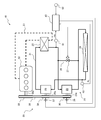
- FIG. 1 shows a schematic configuration of an exhaust heat recovery apparatus 1 according to a first embodiment of the present invention.
- the exhaust heat recovery apparatus 1 is mounted on a vehicle and recovers and uses the exhaust heat of the engine 50 of the vehicle.
- the exhaust heat recovery apparatus 1 includes a Rankine cycle 2 that recovers exhaust heat of the engine 50 and converts it into power, and a power transmission mechanism that transmits power between the Rankine cycle 2 and the engine 50. 3 and a control unit 4 that controls the operation of the exhaust heat recovery apparatus 1 as a whole.
- the engine 50 is a water-cooled internal combustion engine, and is cooled by engine cooling water that circulates in the cooling water passage 51.
- a heater 22 of the Rankine cycle 2 described later is disposed in the cooling water passage 51, and engine cooling water that has absorbed heat from the engine 50 flows through the heater 22.
- a heater 22, an expander 23, a condenser 24, and a pump 25 are arranged in this order. Further, a bypass channel 26 is provided between the heater 22 and the condenser 24 to bypass the expander 23 and distribute the refrigerant.
- the bypass passage 26 is opened and closed by a bypass valve 27 that is controlled by the control unit 4.
- the heater 22 is a heat exchanger that heats the refrigerant into superheated steam by causing heat exchange between the engine coolant that has absorbed heat from the engine 50 and the refrigerant.
- the heater 22 may be configured to exchange heat between the exhaust of the engine 10 and the refrigerant instead of the engine cooling water.
- the expander 23 is, for example, a scroll expander, and generates power by expanding the refrigerant that has been heated by the heater 22 into superheated steam and converting it into rotational energy.
- the condenser 24 is a heat exchanger that cools and condenses (liquefies) the refrigerant by causing heat exchange between the refrigerant that passes through the expander 23 and the outside air.
- the pump 25 is a mechanical pump that sends out the refrigerant (liquid refrigerant) liquefied by the condenser 24 to the heater 22. Then, the refrigerant liquefied by the condenser 24 is sent to the heater 22 by the pump 25, so that the refrigerant circulates through each element of the Rankine cycle 2.
- the expander 23 and the pump 25 are configured as a “pump-integrated expander 28” in which the expander 23 and the pump 25 are integrally connected by a common rotating shaft 28a. That is, the rotary shaft 28 a of the pump-integrated expander 28 has a function as an output shaft of the expander 23 and a drive shaft of the pump 25.
- the power transmission mechanism 3 includes an electromagnetic clutch 31, a pulley 32 attached to the rotary shaft 28 a of the pump-integrated expander 28 via the electromagnetic clutch 31, and a crank pulley 33 attached to the crankshaft 50 a of the engine 50. And a belt 34 wound around the pulley 32 and the crank pulley 33.
- the electromagnetic clutch 31 is ON (engaged) / OFF (released) controlled by the control unit 4, whereby the power transmission mechanism 3 transmits power between the engine 50 and the Rankine cycle 2 (pump-integrated expander 28). It can be transmitted / blocked.
- the control unit 4 detects the first pressure sensor 61 that detects the high pressure PH of the Rankine cycle 2, the second pressure sensor 62 that detects the low pressure PL of the Rankine cycle 2, and the rotational speed Nex of the expander 23. Detection signals of various sensors such as the rotation sensor 63 are input.
- the control unit 4 is configured to be able to transmit and receive information to and from the vehicle control device (not shown).
- the control unit 4 executes various controls including start control and stop control of the Rankine cycle 2 based on the detection signals of the various sensors input and information from the vehicle control device.
- the high-pressure side pressure PH of the Rankine cycle 2 refers to the pressure in the refrigerant circuit 21 in the section from the pump 25 (exit) through the heater 22 to the expander 23 (inlet).
- the low pressure PL in the cycle 2 refers to the pressure in the refrigerant circuit 21 in the section from the expander 23 (exit) to the pump 25 (inlet) via the condenser 24.
- the first pressure sensor 51 detects the pressure at the inlet side of the expander 23 (the outlet side of the heater 22) as the high pressure side pressure PH of the Rankine cycle 2
- the second pressure sensor 52 is the inlet of the pump 25.
- the pressure on the side (the outlet side of the condenser 23) is detected as the low pressure side pressure PL of the Rankine cycle 2.
- start control Rankine start control
- stop control Rankine stop control
- the control unit 4 executes Rankine activation control when the activation condition of the Rankine cycle 2 is satisfied.
- the control unit 4 first operates the pump 25 by engaging the electromagnetic clutch 31 with the bypass valve 27 opened, and then the high pressure side pressure PH and the low pressure side pressure PL of the Rankine cycle 2 are operated.
- the pressure difference ⁇ P with respect to becomes equal to or greater than the first predetermined value ⁇ Ps1 the bypass valve 27 is closed.
- the first predetermined value ⁇ Ps1 is set in advance as a pressure difference between the high pressure side and the low pressure side of the Rankine cycle 2 when a sufficient amount (approximately 100%) of liquid refrigerant is supplied to the inlet side of the pump 25. Value.
- the second predetermined value ⁇ Ps2 is a value set in advance as a start completion determination value of Rankine cycle 2.
- the control unit 4 when starting the Rankine cycle 2, the control unit 4 first bypasses the expander 23, circulates the refrigerant, and bypasses when the refrigerant on the inlet side of the pump 25 is sufficiently liquefied.
- the valve 27 is closed and the refrigerant is circulated through the expander 23.
- Rankine stop control For example, the control unit 4 executes Rankine stop control when it is determined that the Rankine cycle 2 needs to be stopped or when a stop request for the Rankine cycle 2 is received from the vehicle control device.
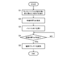
- FIG. 2 is a flowchart of Rankine stop control.
- step S2 the standby time Ta is set (calculated) based on the pressure difference ⁇ P.
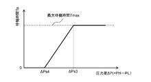
- the control unit 4 obtains the waiting time Ta by referring to a “waiting time setting table” as shown in FIG. 3 based on the pressure difference ⁇ P.
- the waiting time Ta can be calculated by multiplying the pressure difference ⁇ P by a predetermined coefficient.
- the waiting time Ta is a time (predicted time) required from when the bypass valve 27 is opened until the output of the expander 23 becomes sufficiently small (for example, the output of the expander 23 becomes almost zero).
- the larger the difference ⁇ P the longer the waiting time Ta.
- a maximum value (maximum standby time Tmax) is set for the standby time Ta, and when the pressure difference ⁇ P is equal to or greater than a third predetermined value ⁇ Ps3, the standby time Ta is set. Is the maximum standby time Tmax.
- the pressure difference ⁇ P is equal to or smaller than the fourth predetermined value ⁇ Ps4 ( ⁇ Ps3), the waiting time Ta is 0 (s).
- step S3 the bypass valve 27 is opened. Thereby, a refrigerant
- step S4 it is determined whether or not the standby time Ta has elapsed since the bypass valve 27 was opened. When the standby time Ta has elapsed, the process proceeds to step S5.
- step S ⁇ b> 5 the electromagnetic clutch 31 is released to interrupt power transmission between the engine 50 and the pump-integrated expander 28. Thereby, the expander 23 and the pump 25 are stopped, and the Rankine cycle 2 is stopped.
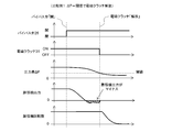
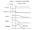
- FIGS. 5 and 6 are diagrams for explaining the effect of the Rankine stop control.
- FIG. 4 shows a time chart of the Rankine stop control
- FIGS. 5 and 6 show Comparative Examples 1 and 2.
- FIG. Here, in Comparative Example 1 (FIG. 5), when the Rankine cycle 2 is stopped, the bypass valve 27 is first opened, and then the electromagnetic clutch 31 is released when the pressure difference ⁇ P decreases to a predetermined threshold value. In Comparative Example 2 (FIG. 6), when the Rankine cycle 2 is stopped, the bypass valve 27 is opened and the electromagnetic clutch 31 is released almost simultaneously.
- the expander 23 does not generate power before the pressure difference ⁇ P decreases to the predetermined threshold value, that is, before the electromagnetic clutch 31 is released, and the expander is indicated by hatching in FIG.
- the expander 23 becomes a load on the engine 50 (the output of the expander 23 is negative) until the electromagnetic clutch 31 is released after no power is generated by the power generator 23. That is, in Comparative Example 1, the timing for releasing the electromagnetic clutch 31 is too late. For this reason, the fuel consumption of the engine 50 may be reduced, or the drivability of the vehicle may be deteriorated.
- the output of the expander 23 becomes sufficiently small (almost 0) after the bypass valve 27 is opened based on the pressure difference ⁇ P immediately before the bypass valve 27 is opened. Is calculated (predicted) as a waiting time Ta, and after opening the bypass valve 27, the electromagnetic clutch 31 is released when the waiting time Ta elapses. Therefore, the timing of releasing the electromagnetic clutch 31 is not too late as in Comparative Example 1, or the timing of releasing the electromagnetic clutch 31 is not too early as in Comparative Example 2, as shown in FIG. The electromagnetic clutch 31 can be released at the timing when the output of the expander 23 becomes almost zero.
- the control unit 4 when stopping the Rankine cycle 2, the control unit 4 first opens the bypass valve 27, and then the waiting time Ta corresponding to the pressure difference ⁇ P immediately before opening the bypass valve 27 elapses. If so, the electromagnetic clutch 31 is controlled to be released. As a result, the output of the expander 23 is quickly reduced and the electromagnetic clutch 31 is released at a timing when the output of the expander 23 becomes almost zero, so that the power between the engine 50 and Rankine cycle 2 (expander 23) is reduced. Transmission can be cut off. As a result, it is possible to effectively prevent the expander 23 from over-rotating or the expander 23 from becoming a load on the engine 50 when the Rankine cycle 2 is stopped.
- the standby time Ta is set (calculated) based on the pressure difference ⁇ P immediately before the control unit 4 opens the bypass valve 27. Instead, the bypass valve 27 is opened.
- the waiting time Ta may be set based on the pressure difference ⁇ P at the time. In this case, for example, the pressure difference ⁇ P can be detected at the same time when an opening command is output to the bypass valve 27. That is, the waiting time Ta can be set based on the pressure difference ⁇ P before or when the bypass valve 27 is opened.
- the control unit 4 may be configured to correct the difference between the waiting time Ta and the actual time by correcting the waiting time Ta.
- the control unit 4 monitors the rotational speed Nex of the expander 23, and when the rotational speed Nex of the expander 23 exceeds a predetermined rotational speed (for example, 2000 rpm) immediately after releasing the electromagnetic clutch 31, the expander 23 It is determined that over-rotation occurred.
- a predetermined rotational speed for example, 2000 rpm
- the control unit 4 performs the Rankine stop control after the next time.
- the standby time Ta calculated in step S2 is extended and corrected. In this case, for example, an upper limit value is set for the waiting time Ta so that the correction is not made more than necessary.
- the control unit 4 immediately opens the bypass valve 27, and then turns on the electromagnetic clutch 31 when the second standby time Ta2 shorter than the standby time Ta elapses.
- the second standby time Ta2 is a time required for the output of the expander 23 to decrease to the extent that the torque shock and the unintended vehicle advance do not occur after the bypass valve 27 is opened, Similar to the waiting time Ta, it can be calculated (predicted) based on the pressure difference ⁇ P. Thereby, generation
- the present invention is not limited to this, and the control unit 4 may shorten and correct the waiting time Ta calculated in step S ⁇ b> 2 when a stop operation of the engine 10 occurs.
- FIG. 7 shows a schematic configuration of the exhaust heat recovery apparatus 10 according to the second embodiment of the present invention.
- the exhaust heat recovery apparatus 1 according to the first embodiment is configured as a “pump-integrated expander 28” in which the expander 23 and the pump 25 constituting the Rankine cycle are integrally connected by a common rotating shaft 28a.
- the expander 23 and the pump 25 constituting the Rankine cycle are provided separately.
- the same elements as those in FIG. 1 are denoted by the same reference numerals, and the functions thereof are also the same.
- the exhaust heat recovery apparatus 10 includes a Rankine cycle 20 in which the expander 23 and the pump 25 are configured separately, a power transmission mechanism 30, and a control unit 40. Since the basic configuration of the Rankine cycle 20 is the same as that of the Rankine cycle 2 in the first embodiment, the description thereof is omitted.
- the power transmission mechanism 30 includes a crank pulley 33 attached to the crankshaft 50a of the engine 50, and an expander pulley 36 attached to the output shaft 23a of the expander 23 via a first electromagnetic clutch (expander clutch) 35. And a pump pulley 38 attached to a drive shaft 25a of the pump 25 via a second electromagnetic clutch (pump clutch) 37, and a belt 39 wound around the crank pulley 32, the expander pulley 36 and the pump pulley 38.
- the control unit 40 performs start control (Rankine start control) and stop control (Rankine stop control) of the Rankine cycle 20 as in the first embodiment.
- the control unit 40 When starting the Rankine cycle 20, the control unit 40 first opens the bypass valve 27 and turns on (fastens) the second electromagnetic clutch 37 to operate the pump 25, and then the high pressure side pressure PH of the Rankine cycle 20 is set. When the pressure difference ⁇ P with respect to the low-pressure side pressure PL becomes equal to or larger than the first predetermined value ⁇ Ps1, the bypass valve 27 is controlled to be closed after the first electromagnetic clutch 35 is turned on (engaged). When the pump 25 is an electric pump, the control unit 40 outputs a drive signal to the pump 25 instead of turning on the second electromagnetic clutch 37.
- FIG. 8 is a flowchart of Rankine stop control executed by the control unit 40.
- steps S11 and S12 as in steps S1 and S2 of FIG. 2, a pressure difference ⁇ P between the high pressure side pressure PH and the low pressure side pressure PL of the Rankine cycle 20 is detected, and based on the detected pressure difference ⁇ P.
- the standby time Tb is calculated.
- step S13 the bypass valve 27 is opened as in step S3 of FIG.
- step S ⁇ b> 14 the second electromagnetic clutch (pump clutch) 37 is released to interrupt the transmission of power between the engine 50 and the pump 25. Thereby, the pump 25 is stopped. In the case of an electric pump, the electric pump is stopped by outputting a stop signal.
- steps S13 and S14 the refrigerant stops flowing through the expander 23, and the output of the expander 23 begins to decrease.
- the pump clutch 37 is released after the bypass valve 27 is opened, but the bypass valve 27 may be opened after the pump clutch 37 is released, or both may be performed simultaneously.
- step S15 it is determined whether or not the standby time Tb has elapsed since the bypass valve 27 was opened.
- the process proceeds to step S16.
- step S ⁇ b> 16 the first electromagnetic clutch (expander clutch) 35 is released to interrupt transmission of power between the engine 50 and the expander 23. Thereby, the expander 23 is stopped and the Rankine cycle 20 is stopped.
- the same effect as the exhaust heat recovery apparatus 1 according to the first embodiment can be obtained. That is, when the Rankine cycle 20 is stopped, the output of the expander 23 is quickly reduced and the expander clutch 35 is released at a timing when the output of the expander 23 becomes almost zero, so that the engine 50 and Rankine cycle 20 (expansion) Transmission of power to and from the machine 23) can be cut off. As a result, it is possible to effectively prevent the expander 23 from over-rotating and the expander 23 from becoming a load on the engine 50.
- the standby time Tb may be set based on the pressure difference ⁇ P when the bypass valve 27 is opened.
- the standby time Tb may be extended and corrected in the next Rankine stop control. Further, when the stop operation of the engine 50 occurs, the bypass valve 27 is immediately opened, and then the expander clutch 35 is released when the second standby time Tb2 shorter than the standby time Tb has elapsed. May be.
- the standby times Ta and Tb are set according to the pressure difference ⁇ P.
- some values indicating the operating state or operating conditions of the Rankine cycles 2 and 20 before the bypass valve 27 is opened or when the bypass valve 27 is opened are expanded after the bypass valve 27 is opened. It has been confirmed that there is a correlation with the time until the output of the machine 23 becomes sufficiently small (substantially becomes 0), and the standby times Ta and Tb can be set based on these.
- FIG. 9 shows an example of a standby time setting table that can be used in place of the above-mentioned “standby time setting table (FIG. 3)”.
- FIG. 9A shows an example of a standby time setting table used for setting the standby times Ta and Tb based on the high pressure PH of Rankine cycles 2 and 20.
- the standby times Ta and Tb become longer as the high pressure side pressure PH becomes higher.
- a primary relational expression is established between the high pressure side pressure PH and the standby times Ta and tb. Therefore, the standby times Ta and Tb are obtained by multiplying the high pressure side pressure PH by a predetermined coefficient. Can be calculated.
- FIG. 9B shows an example of a standby time setting table used for setting the standby times Ta and Tb based on the torque Tex of the expander 23.
- the standby times Ta and Tb become longer as the expander torque Tex becomes larger.
- the standby times Ta and Tb may be calculated by multiplying the expander torque Tex by a predetermined coefficient.
- FIG. 9C shows an example of a standby time setting table used for setting the standby times Ta and Tb based on the outside air temperature To.
- the standby times Ta and Tb become shorter as the outside air temperature To becomes higher.
- the standby times Ta and Tb may be calculated by multiplying the outside air temperature To by a predetermined coefficient.
- FIG. 9D shows an example of a standby time setting table used for setting the standby times Ta and Tb based on the vehicle speed Vs.
- the standby times Ta and Tb become longer as the vehicle speed Vs becomes higher.
- the standby times Ta and Tb may be calculated by multiplying the vehicle speed Vs by a predetermined coefficient.
- the control unit 4 obtains the vehicle speed Vs from the vehicle control device.
- the maximum standby time Tmax may be set similarly to the “standby time setting table” shown in FIG.
- the exhaust heat recovery apparatus is mounted on a vehicle and recovers and uses the exhaust heat of the engine of the vehicle.
- the present invention is an exhaust heat from an external heat source other than the vehicle engine. It is also possible to apply to an exhaust heat recovery device that recovers and uses the heat.
Landscapes
- Engineering & Computer Science (AREA)
- Chemical & Material Sciences (AREA)
- Combustion & Propulsion (AREA)
- Mechanical Engineering (AREA)
- General Engineering & Computer Science (AREA)
- Engine Equipment That Uses Special Cycles (AREA)
- Control Of Turbines (AREA)
Abstract
Description
この特許文献1に記載の廃熱利用装置では、膨張機の出力によってポンプが駆動され、その余剰出力によってモータジェネレータが駆動される。
図1は、本発明の第1実施形態による排熱回収装置1の概略構成を示している。この排熱回収装置1は、車両に搭載され、当該車両のエンジン50の排熱を回収して利用する。図1に示すように、排熱回収装置1は、エンジン50の排熱を回収して動力に変換するランキンサイクル2と、ランキンサイクル2とエンジン50との間で動力の伝達を行う動力伝達機構3と、排熱回収装置1全体の作動を制御する制御ユニット4と、を含む。
凝縮器24は、膨張機23を経由した冷媒と外気との間で熱交換を行わせることによって冷媒を冷却して凝縮(液化)させる熱交換器である。
(ランキン起動制御)
制御ユニット4は、例えば、ランキンサイクル2の起動条件が成立すると、ランキン起動制御を実行する。制御ユニット4は、ランキンサイクル2を起動させる場合、まずバイパス弁27を開いた状態で電磁クラッチ31を締結してポンプ25を作動させ、その後、ランキンサイクル2の高圧側圧力PHと低圧側圧力PLとの圧力差ΔPが第1所定値ΔPs1以上となるとバイパス弁27を閉じる。ここで、第1所定値ΔPs1は、ポンプ25入口側に十分な量(ほぼ100%)の液冷媒が供給されている場合のランキンサイクル2の高圧側と低圧側の圧力差としてあらかじめ設定された値である。
制御ユニット4は、例えば、ランキンサイクル2を停止させる必要があると判断した場合や上記車両の制御装置からランキンサイクル2の停止要求を受けた場合に、ランキン停止制御を実行する。図2は、ランキン停止制御のフローチャートである。
ステップS2では、上記圧力差ΔPに基づいて待機時間Taを設定(算出)する。例えば、制御ユニット4は、上記圧力差ΔPに基づき、図3に示すような「待機時間設定テーブル」を参照することによって上記待機時間Taを得る。また、図3からも明らかなように、上記待機時間Taは、上記圧力差ΔPに所定の係数を乗じて算出することもできる。
ステップS4では、バイパス弁27を開いてから上記待機時間Taが経過したか否かを判断し、上記待機時間Taが経過するとステップS5に進む。
ステップS5では、電磁クラッチ31を解放してエンジン50とポンプ一体型膨張機28との間の動力の伝達を遮断する。これにより、膨張機23及びポンプ25が停止され、ランキンサイクル2が停止される。
図4は、上記ランキン停止制御のタイムチャートを示しており、図5、図6は、比較例1,2を示している。ここで、比較例1(図5)では、ランキンサイクル2を停止させる際に、まずバイパス弁27を開き、その後、上記圧力差ΔPが所定の閾値まで低下したときに電磁クラッチ31を解放する。また、比較例2(図6)では、ランキンサイクル2を停止させる際に、バイパス弁27を開くこと及び電磁クラッチ31を解放することをほぼ同時に行う。
図7は、本発明の第2実施形態による排熱回収装置10の概略構成を示している。
上記第1実施形態による排熱回収装置1では、ランキンサイクルを構成する膨張機23とポンプ25とが共通の回転軸28aによって一体に連結された「ポンプ一体型膨張機28」として構成されている。これに対し、第2実施形態による排熱回収装置10では、ランキンサイクルを構成する膨張機23とポンプ25とが別々に設けられている。なお、図1と同一の要素については同一の符号を付しており、その機能も同様であるものとする。
制御ユニット40は、ランキンサイクル20を起動させる際に、まずバイパス弁27を開くと共に第2電磁クラッチ37をON(締結)してポンプ25を作動させ、その後、ランキンサイクル20の高圧側圧力PHと低圧側圧力PLとの圧力差ΔPが第1所定値ΔPs1以上となると、第1電磁クラッチ35をON(締結)した上でバイパス弁27を閉じるように制御する。なお、ポンプ25を電動ポンプとした場合、制御ユニット40は、第2電磁クラッチ37をONすることに代えてポンプ25に駆動信号を出力する。
図8は、制御ユニット40によって実行されるランキン停止制御のフローチャートである。図8において、ステップS11,S12では、図2のステップS1,S2と同様、ランキンサイクル20の高圧側圧力PHと低圧側圧力PLとの圧力差ΔPを検知し、検知された圧力差ΔPに基づき待機時間Tbを算出する。
ステップS14では、第2電磁クラッチ(ポンプクラッチ)37を解放してエンジン50とポンプ25との間の動力の伝達を遮断する。これにより、ポンプ25が停止される。なお、電動ポンプの場合には、停止信号を出力することによって当該電動ポンプを停止させる。
上記ステップS13,S14によって、冷媒が膨張機23を流通しなくなり、膨張機23の出力が低下し始める。なお、ここでは、バイパス弁27を開いた後にポンプクラッチ37を解放しているが、ポンプクラッチ37を解放した後にバイパス弁27を開いてもよいし、両方を同時に行ってもよい。
ステップS16では、第1電磁クラッチ(膨張機クラッチ)35を解放してエンジン50と膨張機23との間の動力の伝達を遮断する。これにより、膨張機23が停止され、ランキンサイクル20が停止される。
図9(a)は、ランキンサイクル2,20の高圧側圧力PHに基づいて待機時間Ta,Tbを設定するために用いる待機時間設定テーブルの例を示している。図9(a)に示すように、基本的には、高圧側圧力PHが高くなるほど待機時間Ta,Tbが長くなる。圧力差ΔPの場合と同様に、高圧側圧力PHと待機時間Ta,tbとの間には一次関係式が成立するので、待機時間Ta,Tbは、高圧側圧力PHに所定の係数を乗じて算出することができる。
なお、図9(a)~(d)に示す「待機時間設定テーブル」においても、図3に示す「待機時間設定テーブル」と同様に、最大待機時間Tmaxを設定するようにしてもよい。
Claims (10)
- 冷媒の循環路に、エンジンの排熱によって冷媒を加熱して気化させる加熱器、この加熱器を経由した冷媒を膨張させて動力を発生する膨張機、この膨張機を経由した冷媒を凝縮させる凝縮器、及びこの凝縮器を経由した冷媒を前記加熱器へと送出するポンプが配設されたランキンサイクルと、
前記膨張機を迂回して前記冷媒を流通させるバイパス流路と、
前記バイパス流路を開閉するバイパス弁と、
クラッチ機構を有し、当該クラッチ機構の締結時に前記膨張機と前記エンジンとの間で動力の伝達が可能な動力伝達機構と、
前記ランキンサイクルを停止させる際に、前記バイパス弁を開き、その後、前記バイパス弁を開く以前又は前記バイパス弁を開いた時点の前記ランキンサイクルの運転状態又は運転条件に応じて設定される待機時間が経過したときに前記クラッチ機構を解放するように制御する制御部と、
を備えた、排熱回収装置。 - 前記待機時間は、前記運転状態又は前記運転条件を示す値に所定の係数を乗じて算出される、請求項1に記載の排熱回収装置。
- 前記ランキンサイクルの高圧側と低圧側との圧力差を検知する圧力差検知部を備え、
前記運転状態又は前記運転条件を示す値として前記ランキンサイクルの高圧側と低圧側との圧力差を用いる、請求項2に記載の排熱回収装置。 - 前記ランキンサイクルの高圧側の圧力を検知する圧力検知部を備え、
前記運転状態又は前記運転条件を示す値として前記ランキンサイクルの高圧側の圧力を用いる、請求項2に記載の排熱回収装置。 - 前記膨張機のトルクを推定又は検知するトルク検知部を備え、
前記運転状態又は前記運転条件を示す値として前記膨張機のトルクを用いる、請求項2に記載の排熱回収装置。 - 外気温度を検知する温度検知部を備え、
前記運転状態又は前記運転条件を示す値として外気温度を用いる、請求項2に記載の排熱回収装置。 - 前記排熱回収装置は車両に搭載されたものであり、前記運転状態又は前記運転条件を示す値として車速を用いる、請求項2に記載の排熱回収装置。
- 前記膨張機の回転数を検知する回転数検知部をさらに備え、
前記制御部は、前記クラッチ機構を解放した後に前記膨張機の回転数が所定回転数を超える前記膨張機の過回転が発生した場合には、次に前記ランキンサイクルを停止させる際に前記待機時間を延長補正する、請求項1~7のいずれか一つに記載の排熱回収装置。 - 前記制御部は、前記ランキンサイクルの運転中に前記エンジンの停止操作が発生した場合には、直ちに前記バイパス弁を開き、その後、前記待機時間よりも短い第2の待機時間が経過したときに前記クラッチ機構を解放するように制御する、請求項1~8のいずれか一つに記載の排熱回収装置。
- 前記ランキンサイクルにおける前記膨張機及び前記ポンプが一体に連結されている、請求項1~9のいずれか一つに記載の排熱回収装置。
Priority Applications (2)
| Application Number | Priority Date | Filing Date | Title |
|---|---|---|---|
| DE112014001713.2T DE112014001713B4 (de) | 2013-03-28 | 2014-03-26 | Abwärmerückgewinnungsvorrichtung |
| US14/780,614 US9957845B2 (en) | 2013-03-28 | 2014-03-26 | Exhaust heat recovery device |
Applications Claiming Priority (2)
| Application Number | Priority Date | Filing Date | Title |
|---|---|---|---|
| JP2013069540A JP5999652B2 (ja) | 2013-03-28 | 2013-03-28 | 排熱回収装置 |
| JP2013-069540 | 2013-03-28 |
Publications (1)
| Publication Number | Publication Date |
|---|---|
| WO2014157300A1 true WO2014157300A1 (ja) | 2014-10-02 |
Family
ID=51624263
Family Applications (1)
| Application Number | Title | Priority Date | Filing Date |
|---|---|---|---|
| PCT/JP2014/058449 Ceased WO2014157300A1 (ja) | 2013-03-28 | 2014-03-26 | 排熱回収装置 |
Country Status (4)
| Country | Link |
|---|---|
| US (1) | US9957845B2 (ja) |
| JP (1) | JP5999652B2 (ja) |
| DE (1) | DE112014001713B4 (ja) |
| WO (1) | WO2014157300A1 (ja) |
Families Citing this family (10)
| Publication number | Priority date | Publication date | Assignee | Title |
|---|---|---|---|---|
| CN104603439B (zh) * | 2012-07-09 | 2016-08-17 | 三电控股株式会社 | 发动机的废热利用装置 |
| JP6156410B2 (ja) * | 2015-02-25 | 2017-07-05 | トヨタ自動車株式会社 | ランキンサイクルシステム |
| JP6549955B2 (ja) * | 2015-09-28 | 2019-07-24 | 株式会社Subaru | 廃熱利用装置 |
| JP6637280B2 (ja) * | 2015-09-29 | 2020-01-29 | 株式会社Subaru | 車両の制御装置 |
| AT518636B1 (de) * | 2016-05-17 | 2017-12-15 | Avl List Gmbh | Verfahren zum betreiben einer brennkraftmaschine für ein fahrzeug |
| DE102016217764A1 (de) * | 2016-09-16 | 2018-03-22 | Robert Bosch Gmbh | Abwärmerückgewinnungssystem |
| JP2018150873A (ja) * | 2017-03-13 | 2018-09-27 | いすゞ自動車株式会社 | ランキンサイクルシステム、及び、ランキンサイクルシステムの制御方法 |
| JP2019143533A (ja) * | 2018-02-20 | 2019-08-29 | いすゞ自動車株式会社 | 廃熱利用装置 |
| SE543286C2 (en) * | 2019-03-20 | 2020-11-17 | Scania Cv Ab | Control unit, waste heat recovery system, vehicle comprising such a system, and method for starting an expansion device of a waste heat recovery system |
| CN113756897B (zh) * | 2021-09-01 | 2022-12-16 | 一汽解放汽车有限公司 | 车用有机朗肯循环余热回收装置的启停控制方法 |
Citations (6)
| Publication number | Priority date | Publication date | Assignee | Title |
|---|---|---|---|---|
| US20090211253A1 (en) * | 2005-06-16 | 2009-08-27 | Utc Power Corporation | Organic Rankine Cycle Mechanically and Thermally Coupled to an Engine Driving a Common Load |
| JP2010101283A (ja) * | 2008-10-27 | 2010-05-06 | Toyota Motor Corp | 廃熱回収装置 |
| JP2011149373A (ja) * | 2010-01-22 | 2011-08-04 | Toyota Motor Corp | 廃熱回収装置 |
| JP2012041933A (ja) * | 2011-10-25 | 2012-03-01 | Sanden Corp | ランキン回路及び車両の廃熱利用システム |
| JP2012193690A (ja) * | 2011-03-17 | 2012-10-11 | Sanden Corp | 自動車用廃熱利用システム |
| JP2013076374A (ja) * | 2011-09-30 | 2013-04-25 | Nissan Motor Co Ltd | ランキンサイクル及びランキンサイクルに用いる熱交換器 |
Family Cites Families (6)
| Publication number | Priority date | Publication date | Assignee | Title |
|---|---|---|---|---|
| US4590384A (en) * | 1983-03-25 | 1986-05-20 | Ormat Turbines, Ltd. | Method and means for peaking or peak power shaving |
| JPH09387A (ja) | 1995-06-23 | 1997-01-07 | Hitachi Constr Mach Co Ltd | 建設機械の運転席装置 |
| US6450283B1 (en) | 2000-11-27 | 2002-09-17 | Michael Blake Taggett | Waste heat conversion system |
| JP2009097387A (ja) | 2007-10-15 | 2009-05-07 | Denso Corp | 廃熱利用装置 |
| JP2011214480A (ja) * | 2010-03-31 | 2011-10-27 | Sanden Corp | 内燃機関の廃熱利用装置 |
| JP5804879B2 (ja) | 2011-09-30 | 2015-11-04 | 日産自動車株式会社 | 廃熱利用装置 |
-
2013
- 2013-03-28 JP JP2013069540A patent/JP5999652B2/ja not_active Expired - Fee Related
-
2014
- 2014-03-26 US US14/780,614 patent/US9957845B2/en active Active
- 2014-03-26 WO PCT/JP2014/058449 patent/WO2014157300A1/ja not_active Ceased
- 2014-03-26 DE DE112014001713.2T patent/DE112014001713B4/de not_active Expired - Fee Related
Patent Citations (6)
| Publication number | Priority date | Publication date | Assignee | Title |
|---|---|---|---|---|
| US20090211253A1 (en) * | 2005-06-16 | 2009-08-27 | Utc Power Corporation | Organic Rankine Cycle Mechanically and Thermally Coupled to an Engine Driving a Common Load |
| JP2010101283A (ja) * | 2008-10-27 | 2010-05-06 | Toyota Motor Corp | 廃熱回収装置 |
| JP2011149373A (ja) * | 2010-01-22 | 2011-08-04 | Toyota Motor Corp | 廃熱回収装置 |
| JP2012193690A (ja) * | 2011-03-17 | 2012-10-11 | Sanden Corp | 自動車用廃熱利用システム |
| JP2013076374A (ja) * | 2011-09-30 | 2013-04-25 | Nissan Motor Co Ltd | ランキンサイクル及びランキンサイクルに用いる熱交換器 |
| JP2012041933A (ja) * | 2011-10-25 | 2012-03-01 | Sanden Corp | ランキン回路及び車両の廃熱利用システム |
Also Published As
| Publication number | Publication date |
|---|---|
| US9957845B2 (en) | 2018-05-01 |
| JP2014190326A (ja) | 2014-10-06 |
| US20160076403A1 (en) | 2016-03-17 |
| DE112014001713T5 (de) | 2015-12-10 |
| DE112014001713B4 (de) | 2018-06-14 |
| JP5999652B2 (ja) | 2016-09-28 |
Similar Documents
| Publication | Publication Date | Title |
|---|---|---|
| JP5999652B2 (ja) | 排熱回収装置 | |
| JP4302759B2 (ja) | 廃熱利用装置 | |
| JP6143755B2 (ja) | エンジンの廃熱利用装置 | |
| US20110088394A1 (en) | Waste heat regeneration system | |
| JP2010065587A (ja) | 廃熱利用装置 | |
| CN104271891B (zh) | 废热回收装置 | |
| CN104271899B (zh) | 废热回收装置 | |
| JP2009097387A (ja) | 廃熱利用装置 | |
| JP6207941B2 (ja) | 排熱回収装置 | |
| JP6604355B2 (ja) | 廃熱回収装置 | |
| US10138842B2 (en) | Apparatus for utilizing heat wasted from engine | |
| US9988945B2 (en) | Apparatus for utilizing heat wasted from engine | |
| JP2013119831A (ja) | 動力回収装置 | |
| WO2014157298A1 (ja) | 排熱回収装置 | |
| WO2014157299A1 (ja) | 排熱回収装置 | |
| US20190383177A1 (en) | Thermal energy recovery device and startup operation method for the same |
Legal Events
| Date | Code | Title | Description |
|---|---|---|---|
| 121 | Ep: the epo has been informed by wipo that ep was designated in this application |
Ref document number: 14776513 Country of ref document: EP Kind code of ref document: A1 |
|
| WWE | Wipo information: entry into national phase |
Ref document number: 1120140017132 Country of ref document: DE Ref document number: 112014001713 Country of ref document: DE |
|
| WWE | Wipo information: entry into national phase |
Ref document number: 14780614 Country of ref document: US |
|
| 122 | Ep: pct application non-entry in european phase |
Ref document number: 14776513 Country of ref document: EP Kind code of ref document: A1 |