WO2014157041A1 - 緩衝装置 - Google Patents
緩衝装置 Download PDFInfo
- Publication number
- WO2014157041A1 WO2014157041A1 PCT/JP2014/057992 JP2014057992W WO2014157041A1 WO 2014157041 A1 WO2014157041 A1 WO 2014157041A1 JP 2014057992 W JP2014057992 W JP 2014057992W WO 2014157041 A1 WO2014157041 A1 WO 2014157041A1
- Authority
- WO
- WIPO (PCT)
- Prior art keywords
- pressure
- chamber
- spring
- free piston
- shock absorber
- Prior art date
Links
Images

Classifications
-
- F—MECHANICAL ENGINEERING; LIGHTING; HEATING; WEAPONS; BLASTING
- F16—ENGINEERING ELEMENTS AND UNITS; GENERAL MEASURES FOR PRODUCING AND MAINTAINING EFFECTIVE FUNCTIONING OF MACHINES OR INSTALLATIONS; THERMAL INSULATION IN GENERAL
- F16F—SPRINGS; SHOCK-ABSORBERS; MEANS FOR DAMPING VIBRATION
- F16F9/00—Springs, vibration-dampers, shock-absorbers, or similarly-constructed movement-dampers using a fluid or the equivalent as damping medium
- F16F9/32—Details
- F16F9/34—Special valve constructions; Shape or construction of throttling passages
- F16F9/348—Throttling passages in the form of annular discs or other plate-like elements which may or may not have a spring action, operating in opposite directions or singly, e.g. annular discs positioned on top of the valve or piston body
- F16F9/3488—Throttling passages in the form of annular discs or other plate-like elements which may or may not have a spring action, operating in opposite directions or singly, e.g. annular discs positioned on top of the valve or piston body characterised by features intended to affect valve bias or pre-stress
-
- F—MECHANICAL ENGINEERING; LIGHTING; HEATING; WEAPONS; BLASTING
- F16—ENGINEERING ELEMENTS AND UNITS; GENERAL MEASURES FOR PRODUCING AND MAINTAINING EFFECTIVE FUNCTIONING OF MACHINES OR INSTALLATIONS; THERMAL INSULATION IN GENERAL
- F16F—SPRINGS; SHOCK-ABSORBERS; MEANS FOR DAMPING VIBRATION
- F16F9/00—Springs, vibration-dampers, shock-absorbers, or similarly-constructed movement-dampers using a fluid or the equivalent as damping medium
- F16F9/32—Details
- F16F9/50—Special means providing automatic damping adjustment, i.e. self-adjustment of damping by particular sliding movements of a valve element, other than flexions or displacement of valve discs; Special means providing self-adjustment of spring characteristics
- F16F9/512—Means responsive to load action, i.e. static load on the damper or dynamic fluid pressure changes in the damper, e.g. due to changes in velocity
- F16F9/5126—Piston, or piston-like valve elements
-
- B—PERFORMING OPERATIONS; TRANSPORTING
- B60—VEHICLES IN GENERAL
- B60G—VEHICLE SUSPENSION ARRANGEMENTS
- B60G13/00—Resilient suspensions characterised by arrangement, location or type of vibration dampers
- B60G13/02—Resilient suspensions characterised by arrangement, location or type of vibration dampers having dampers dissipating energy, e.g. frictionally
- B60G13/06—Resilient suspensions characterised by arrangement, location or type of vibration dampers having dampers dissipating energy, e.g. frictionally of fluid type
- B60G13/08—Resilient suspensions characterised by arrangement, location or type of vibration dampers having dampers dissipating energy, e.g. frictionally of fluid type hydraulic
-
- B—PERFORMING OPERATIONS; TRANSPORTING
- B60—VEHICLES IN GENERAL
- B60G—VEHICLE SUSPENSION ARRANGEMENTS
- B60G15/00—Resilient suspensions characterised by arrangement, location or type of combined spring and vibration damper, e.g. telescopic type
- B60G15/02—Resilient suspensions characterised by arrangement, location or type of combined spring and vibration damper, e.g. telescopic type having mechanical spring
- B60G15/06—Resilient suspensions characterised by arrangement, location or type of combined spring and vibration damper, e.g. telescopic type having mechanical spring and fluid damper
- B60G15/061—Resilient suspensions characterised by arrangement, location or type of combined spring and vibration damper, e.g. telescopic type having mechanical spring and fluid damper with a coil spring being mounted inside the damper
-
- B—PERFORMING OPERATIONS; TRANSPORTING
- B60—VEHICLES IN GENERAL
- B60G—VEHICLE SUSPENSION ARRANGEMENTS
- B60G2202/00—Indexing codes relating to the type of spring, damper or actuator
- B60G2202/20—Type of damper
- B60G2202/24—Fluid damper
Definitions
- the present invention relates to an improvement of a shock absorber.
- JP2008-21559A includes a cylinder, a piston that is slidably inserted into the cylinder and divides the inside of the cylinder into an extension side chamber and a pressure side chamber, a damping passage that communicates the extension side chamber and the pressure side chamber, and a piston.
- a housing that is attached to the tip of the rod to form a pressure chamber, a free piston that is slidably inserted into the pressure chamber and divides the pressure chamber into an expansion side pressure chamber and a pressure side pressure chamber, and a coil that energizes the free piston
- a shock absorber is disclosed that includes a spring, an extension side passage that communicates the extension side chamber and the extension side pressure chamber, and a pressure side passage that communicates the pressure side chamber and the pressure side pressure chamber.
- the extension side chamber and the pressure side chamber do not communicate directly.
- the volume ratio between the expansion side chamber and the compression side chamber changes, and the liquid in the pressure chamber enters and exits the expansion side chamber and the compression side chamber according to the amount of movement of the free piston. For this reason, the shock absorber behaves as if the extension side chamber and the compression side chamber communicate with each other.
- This shock absorber generates a large damping force for low frequency vibration input, while generating a small damping force for high frequency vibration input. For example, a large damping force is generated in a scene where the input vibration frequency is low such as when the vehicle is turning, and a small damping force is generated in a scene where the input vibration frequency is high such that the vehicle passes through unevenness on the road surface. The ride comfort can be improved.
- a step portion is provided on the inner periphery of the housing.
- the shock absorber exhibits a large damping force, and can be prevented from stretching out and having a bottom.
- a hitting sound is generated when the free piston collides with the stepped portion of the housing. This hitting sound is transmitted through the vehicle body and reverberates in the passenger compartment, giving the passenger a sense of discomfort and anxiety and may impair the riding comfort of the vehicle.
- An object of the present invention is to suppress the occurrence of a hitting sound and improve the riding comfort of a vehicle.
- a shock absorber a cylinder, a piston that is slidably inserted into the cylinder and divides the cylinder into an extension side chamber and a pressure side chamber, the extension side chamber, and the pressure side chamber.
- An expansion side passage that communicates with the expansion side pressure chamber, a pressure side passage that communicates the pressure side chamber and the pressure side pressure chamber, and the free piston is positioned in a neutral position with respect to the housing, and the free piston
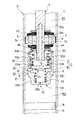
- FIG. 1 is a cross-sectional view of a shock absorber according to an embodiment of the present invention.
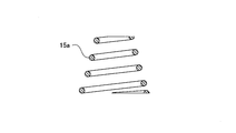
- FIG. 2A is a cross-sectional view of a conical coil spring used as a spring element.
- FIG. 2B is a cross-sectional view of a tapered coil spring used as a spring element.
- the shock absorber D includes a cylinder 1, a piston 2 that is slidably inserted into the cylinder 1, and divides the cylinder 1 into two extension side chambers R ⁇ b> 1 and a compression side chamber R ⁇ b> 2, and an extension side chamber R ⁇ b> 1.
- Damping passages 4 and 5 communicating with the pressure side chamber R2, a housing 6 forming the pressure chamber C, and a pressure chamber C inserted into the housing 6 so as to be slidable, and the expansion side pressure chamber 7 and the pressure side pressure chamber 8
- the expansion side passage 10 that communicates the expansion side chamber R 1 and the expansion side pressure chamber 7, the pressure side passage 11 that communicates the compression side chamber R 2 and the pressure side pressure chamber 8, and the free piston 9.
- An extension side spring 12 and a compression side spring 13, which are spring elements for applying an urging force, are provided.
- the shock absorber D further includes a piston rod 3 that is movably inserted into the cylinder 1.
- One end of the piston rod 3 is connected to the piston 2, and the upper end, which is the other end, is slidably supported by an annular rod guide (not shown) that seals the upper end of the cylinder 1.
- the lower end of the cylinder 1 is sealed with a bottom member (not shown).
- the extension side chamber R1, the pressure side chamber R2, and the pressure chamber C are filled with a liquid such as hydraulic oil.
- a sliding partition 14 that slidably contacts the inner periphery of the cylinder 1 and divides the pressure side chamber R2 and the gas chamber G is provided below the cylinder 1 in FIG.
- a liquid such as water or an aqueous solution may be used in addition to the hydraulic oil.
- the shock absorber D is a single rod type in which the piston rod 3 is inserted only into the extension side chamber R1. For this reason, the volume of the piston rod 3 that enters and exits the cylinder 1 as the shock absorber D expands and contracts is such that the volume of the gas in the gas chamber G expands or contracts and the sliding partition 14 moves up and down in FIG. To be compensated for.
- a reservoir may be provided in the cylinder 1 or outside the cylinder 1 in addition to providing the gas chamber G in the cylinder 1.
- an outer cylinder that covers the outer periphery of the cylinder 1 is provided to form a double cylinder type shock absorber that forms a reservoir between the cylinder 1 and the outer cylinder.
- the reservoir may be formed by the tank.
- a partition member that partitions the pressure side chamber R2 and the reservoir in order to increase the pressure in the pressure side chamber R2 during the contraction operation of the shock absorber D, and a partition member that is provided on the partition member and heads from the pressure side chamber R2 toward the reservoir.
- a base valve that provides resistance to the flow of liquid may be provided.
- the shock absorber D may be a double rod type instead of a single rod type.
- the piston 2 is connected to one end 3a which is the lower end in FIG. 1 of the piston rod 3 that is movably inserted into the cylinder 1.
- the other end of the piston rod 3 protrudes outward through the inner periphery of an annular rod guide (not shown) fixed to the upper end of the cylinder 1 in FIG. Since the space between the piston rod 3 and the rod guide is sealed by a sealing member (not shown), the inside of the cylinder 1 is kept in a liquid-tight state.
- the piston 2 includes two attenuation passages 4 and 5 that communicate the extension side chamber R1 and the pressure side chamber R2.
- the lower end of one damping passage 4 in FIG. 1 is opened and closed by a leaf valve V1 stacked below the piston 2 in FIG.
- the upper end of the other damping passage 5 in FIG. 1 is opened and closed by a leaf valve V2 stacked above the piston 2 in FIG.
- the leaf valve V1 is annular and is attached to the one end 3a of the piston rod 3 together with the piston 2.
- the leaf valve V ⁇ b> 1 is bent when the liquid flows from the extension side chamber R ⁇ b> 1 toward the compression side chamber R ⁇ b> 2 and opens the attenuation passage 4.
- resistance is given to the flow of the liquid, and the damping passage 4 is closed during the contraction stroke of the shock absorber D. That is, the leaf valve V1 uses the damping passage 4 as a one-way passage that allows only the flow from the expansion side chamber R1 to the compression side chamber R2.
- the leaf valve V2 is annular and is attached to the one end 3a of the piston rod 3 together with the piston 2.
- the leaf valve V2 is bent when the liquid flows from the compression side chamber R2 toward the extension side chamber R1 and opens the attenuation passage 5.
- resistance is given to the flow of the liquid, and the damping passage 5 is closed during the expansion stroke of the shock absorber D. That is, the leaf valve V2 uses the damping passage 5 as a one-way passage that allows only the flow from the compression side chamber R2 toward the extension side chamber R1.
- the leaf valve V1 functions as an expansion-side attenuation valve that provides resistance to the flow of liquid flowing through the attenuation passage 4 during the extension stroke, and the leaf valve V2 provides resistance to the flow of liquid that flows through the attenuation passage 5 during the contraction stroke. Functions as a compression side damping valve.
- the attenuation passage may be a one-way passage so that the liquid flows only during the extension stroke or during the contraction stroke, or bidirectional flow is allowed. Thus, resistance may be given to the flow of liquid passing therethrough.
- various attenuation valves such as a poppet valve, an orifice, and a choke can be used in addition to the above-described leaf valve.
- the damping passages 4 and 5 can also be provided in members other than the piston 2.
- the pressure chamber C is formed by a hollow housing 6 that is screwed into a screw portion 3b provided at the outermost periphery of one end 3a of the piston rod 3.
- the housing 6 also functions as a piston nut that fixes the piston 2 and the leaf valves V1, V2 to one end 3a of the piston rod 3.
- the pressure chamber C formed in the housing 6 is partitioned into an upper expansion side pressure chamber 7 and a lower pressure side pressure chamber 8 in FIG. 1 by a free piston 9 slidably inserted into the pressure chamber C.
- the free piston 9 can be displaced in the vertical direction in FIG.
- the housing 6 includes a nut portion 20 that is screwed into a screw portion 3 b formed at one end 3 a of the piston rod 3, and a bottomed cylindrical housing tube 21 that is fixed to the nut portion 20.
- the nut part 20 has a screw cylinder 20a that is screwed into the screw part 3b of the piston rod 3 on the inner periphery, and a flange 20b that is provided on the outer periphery of the screw cylinder 20a and protrudes outward.
- the housing cylinder 21 has a cylinder part 22 whose upper end opening is crimped to the outer periphery of the flange 20b, and a bottom part 23 that closes the lower end part of the cylinder part 22.
- the cylindrical portion 22 is formed between the large-diameter portion 22a on the nut portion side where the free piston 9 is in sliding contact, the small-diameter portion 22b on the counter-nut portion side, and the large-diameter portion 22a and the small-diameter portion 22b.
- a stepped portion 22c In integrating the nut part 20 and the housing cylinder 21, other processing methods such as welding and screwing may be employed in addition to the caulking process.
- the outer peripheral cross-sectional shape of at least a part of the cylindrical portion 22 of the housing cylinder 21 is a shape other than a circle so as to be gripped by a tool (not shown) and matches the tool, for example, a partially cut shape or a six
- the shape is a square or the like.
- the housing 6 is screwed to the screw portion 3b by gripping the outer periphery of the cylindrical portion 22 with a tool and rotating the housing 6 in the circumferential direction.
- An orifice hole 22d is provided in the side portion of the cylindrical portion 22, and an orifice hole 23a is provided in the bottom portion 23.
- the orifice hole 22d and the orifice hole 23a both communicate with the pressure chamber C and the pressure side chamber R2.
- the extension side pressure chamber 7 communicates with the extension side chamber R1 through the extension side passage 10 formed in the piston rod 3.
- the extension side passage 10 is composed of a horizontal hole 10a that opens to the side facing the extension side chamber R1 of the piston rod 3, and a vertical hole 10b that opens to the end of one end 3a and communicates with the horizontal hole 10a.
- the free piston 9 inserted into the pressure chamber C includes a sliding contact cylinder 30 that is in sliding contact with the inner peripheral surface of the inner diameter large diameter portion 22a of the housing cylinder 21, and a bottom portion 31 that closes the lower end of the sliding contact cylinder 30. It is a bottom cylindrical member.
- the free piston 9 further includes an annular recess 32 provided over the entire outer periphery of the sliding contact cylinder 30 and a communication hole 33 that communicates the annular recess 32 with the pressure side pressure chamber 8.
- the pressure side chamber R2 and the pressure side pressure chamber 8 communicate with each other through the orifice hole 22d.
- the pressure side chamber R2 and the pressure side pressure chamber 8 do not communicate with each other through the orifice hole 22d.
- the orifice hole 22d gives resistance to the flow of the liquid passing therethrough to generate a predetermined pressure loss, and creates a pressure difference between the pressure side chamber R2 and the pressure side pressure chamber 8.
- the orifice hole 23a provided in the bottom 23 of the housing cylinder 21 also functions as a throttle passage, and causes a pressure difference between the pressure side chamber R2 and the pressure side pressure chamber 8 in the same manner as the orifice hole 22d.
- the orifice hole 23a provided in the bottom 23 is not closed by the free piston 9 and is always open.
- the pressure side pressure chamber 8 communicates with the pressure side chamber R2 through the two orifice holes 22d and 23a when the orifice hole 22d is in communication, and only the orifice hole 23a when the orifice hole 22d is in the shut-off state.
- the pressure-side passage 11 that communicates the pressure-side chamber R2 and the pressure-side pressure chamber 8 includes orifice holes 22d and 23a, an annular recess 32, and a communication hole 33.
- a spring element is provided in order to suppress the displacement of the free piston 9 with respect to the housing 6.
- the spring elements are in the extension side pressure chamber 7 and in the compression side pressure chamber 8 and the extension side spring 12 interposed between the flange 20b of the nut portion 20 and the bottom 31 of the free piston 9 in a compressed state.
- the compression side spring 13 is interposed between the bottom portion 23 and the bottom portion 31 of the free piston 9 in a compressed state.
- the free piston 9 is sandwiched from above and below by the extension side spring 12 and the pressure side spring 13 and is held at a predetermined neutral position in the pressure chamber C.
- the extension side spring 12 and the compression side spring 13 exert an urging force to return the free piston 9 to the neutral position.
- the neutral position does not indicate the center of the pressure chamber C in the axial direction but is a position where the free piston 9 is positioned by the spring element.
- the extension side spring 12 is an unequal pitch coil spring. During the period from when the free piston 9 is displaced in the direction of compressing the extension side pressure chamber 7 from the neutral position to the end of the stroke, the extension side spring 12 is first brought into close contact with the narrow line portion. Thus, the wide pitch portion is compressed. Thus, the extension side spring 12 has a non-linear characteristic in which the spring constant increases with compression. That is, as the amount of displacement of the free piston 9 increases, the spring constant of the extension side spring 12 gradually increases, and the reaction force by the extension side spring 12 becomes stronger, so that the displacement of the free piston 9 is suppressed.
- the compression side spring 13 is an unequal pitch coil spring, like the extension side spring 12. During the period from when the free piston 9 is displaced in the direction of compressing the compression side pressure chamber 8 from the neutral position to the end of the stroke, the compression side spring 13 is first brought into close contact with the line portion of the narrow pitch, and then the pitch. The wide part of is compressed. Thus, the compression side spring 13 has a non-linear characteristic in which the spring constant increases with compression. That is, as the amount of displacement of the free piston 9 increases, the spring constant of the pressure side spring 13 gradually increases, and the reaction force by the pressure side spring 13 increases, thereby suppressing the displacement of the free piston 9.
- the extension side spring 12 and the compression side spring 13 need only increase in spring constant as the amount of displacement of the free piston 9 increases. Therefore, the conical coil spring 15a in which the spring constant gradually increases with compression shown in FIG. 2A. 2B, or a tapered coil spring 15b whose spring constant increases when the wire diameter shown in FIG. 2B is changed and compressed by a predetermined amount. Further, the extension side spring 12 and the pressure side spring 13 have a long natural length and always come into contact with the free piston 9, and when the free piston 9 has a short natural length and is displaced from the neutral position by a predetermined amount, the free side spring 12 and the compression side spring 13 come into contact with the free piston 9. You may comprise with the spring which exhibits force.
- the free piston 9 is elastically supported in the housing 6 by the extension side spring 12 and the pressure side spring 13 as spring elements.
- the free piston 9 When no force other than the urging force of the extension side spring 12 and the pressure side spring 13 is applied to the free piston 9, the free piston 9 is located in the neutral position in the housing 6.
- the annular recess 32 faces the orifice hole 22d, and the pressure side pressure chamber 8 and the pressure side chamber R2 communicate with each other through the orifice hole 22d.
- the free piston 9 is displaced by a predetermined amount from the neutral position, the outer periphery of the sliding contact cylinder 30 of the free piston 9 completely closes the orifice hole 22d.
- the amount of displacement from the neutral position at which the free piston 9 begins to close the orifice hole 22d can be set arbitrarily.
- the amount of displacement of the free piston 9 starting to close the orifice hole 22d from the neutral position toward the extension side pressure chamber 7, which is the upper side in FIG. 1, and the lower side of the free piston 9 starting to close the orifice hole 22d in FIG. You may set so that it may differ from the displacement amount from the neutral position to the pressure side pressure chamber 8 side.
- two orifice holes 22d are provided, but the number is arbitrary.
- An annular recess may be provided on the inner periphery of the cylindrical portion 22, and an orifice hole that communicates the outer peripheral side of the free piston 9 and the pressure side pressure chamber 8 may be provided in the free piston 9.
- the shock absorber D is configured as described above, and when the free piston 9 moves, the volume ratio between the expansion side chamber R1 and the compression side chamber R2 changes, and the liquid in the pressure chamber C changes according to the amount of movement of the free piston 9. Enter and exit R1 and compression side chamber R2. For this reason, the shock absorber behaves as if the extension side chamber R1 and the compression side chamber R2 communicate with each other.
- the differential pressure between the expansion side chamber R1 and the compression side chamber R2 during expansion and contraction of the shock absorber is P
- the flow rate of the liquid flowing out from the expansion side chamber R1 is Q
- the liquid passing through the differential pressure P and the attenuation passages 4 and 5 The coefficient indicating the relationship with the flow rate Q1 is C1
- the pressure in the expansion side pressure chamber 7 is P1
- the difference between the differential pressure P and the pressure P1 is the flow rate of the liquid flowing into the expansion side pressure chamber 7 from the expansion side chamber R1
- the coefficient indicating the relationship with Q2 is C2
- the pressure in the pressure side pressure chamber 8 is P2
- the coefficient indicating the relationship between the pressure P2 and the flow rate Q2 of the liquid flowing out from the pressure side pressure chamber 8 into the pressure side chamber R2 is C3.
- A is the cross-sectional area that is the pressure receiving area of the free piston 9
- A is the displacement of the free piston 9 relative to the pressure chamber C
- the spring constant of the spring element that is, the combined spring constant of the extension side spring 12 and the pressure side spring 13 is K.
- a large damping force is generated for an input of low-frequency vibration, while a small damping force is exerted for a high-frequency vibration input by exhibiting an effect of reducing the damping force.
- a large damping force is generated in a scene where the input vibration frequency is low such as when the vehicle is turning, and a small damping force is generated in a scene where the input vibration frequency is high such that the vehicle travels on an uneven road surface. The ride comfort of the vehicle can be improved.
- the damping force generated by the shock absorber D1 can be gradually increased, a large damping force is suddenly generated from the state where the shock absorber D1 generates a small damping force at the time of high frequency vibration input. It is possible to prevent the passenger from perceiving a shock due to a change in the damping force.
- the flow passage area of the pressure side passage 11 is decreased in accordance with the displacement of the free piston 9 to gradually increase the flow passage resistance. In addition to this, or instead of this, The same effect can be obtained even if the flow path resistance of the extension side passage 10 is increased.
- the shock absorber D1 receives vibration of a large amplitude in the contracting direction and the free piston 9 is displaced from the neutral position to the expansion side pressure chamber side exceeding a predetermined displacement amount, the spring constant of the expansion side spring 12 is gradually increased. And the urging force acting on the free piston 9 also increases. For this reason, the displacement of the free piston 9 toward the expansion side pressure chamber is suppressed, and the displacement speed of the free piston 9 toward the expansion side pressure chamber decreases. As a result, the free piston 9 is prevented from colliding with the housing 6 vigorously, and the generation of hitting sound is suppressed.
- the shock absorber D1 receives vibration of a large amplitude in the extension direction and the free piston 9 is displaced from the neutral position to the pressure side pressure chamber side exceeding a predetermined displacement amount, the spring constant of the pressure side spring 13 is gradually increased. At the same time, the urging force acting on the free piston 9 is also increased. For this reason, the displacement of the free piston 9 toward the pressure side pressure chamber is suppressed, and the displacement speed of the free piston 9 toward the pressure side pressure chamber decreases. As a result, the free piston 9 is prevented from colliding with the housing 6 vigorously, and the generation of hitting sound is suppressed.
- the shock absorber D according to the present embodiment, it is possible to suppress the generation of the hitting sound by installing the extension side spring 12 and the compression side spring 13 whose spring constant increases with compression. . For this reason, an uneasiness and discomfort are not given to a passenger, and the riding comfort of a vehicle can be improved.
- the shock absorber D incorporated in the suspension of the vehicle has a damping force that is generated when the extension is larger than a damping force that is generated when the vehicle is contracted, and the expansion side chamber R1 is more than the compression side chamber R2.
- the free piston 9 tends to be biased toward the pressure side pressure chamber 8 due to the high pressure. For this reason, there are many opportunities for the free piston 9 to displace in the direction in which the compression side pressure chamber 8 is compressed and collide with the housing 6, but on the other hand, the free piston 9 displaces in the direction to compress the expansion side pressure chamber 7 and collides with the housing 6. There are few opportunities to do. For this reason, even if it sets only the compression side spring 13 so that a spring constant may become large with compression, generation
Landscapes
- Engineering & Computer Science (AREA)
- Mechanical Engineering (AREA)
- General Engineering & Computer Science (AREA)
- Physics & Mathematics (AREA)
- Fluid Mechanics (AREA)
- Fluid-Damping Devices (AREA)
- Vehicle Body Suspensions (AREA)
- Springs (AREA)
Abstract
Description


Claims (4)
- 緩衝装置であって、
シリンダと、
前記シリンダ内に摺動自在に挿入され当該シリンダ内を伸側室と圧側室に区画するピストンと、
前記伸側室と前記圧側室とを連通する減衰通路と、
圧力室を形成するハウジングと、
前記圧力室内に摺動自在に挿入されて当該圧力室を伸側圧力室と圧側圧力室とに区画するフリーピストンと、
前記伸側室と前記伸側圧力室とを連通する伸側通路と、
前記圧側室と前記圧側圧力室とを連通する圧側通路と、
前記フリーピストンを前記ハウジングに対して中立位置に位置決めるとともに当該フリーピストンの中立位置からの変位を抑制する付勢力を発揮するばね要素と、を備え、
前記ばね要素は、前記フリーピストンを挟持する前記伸側圧力室内に収容される伸側ばねおよび前記圧側圧力室内に収容される圧側ばねを有し、
前記圧側ばねは、圧縮に伴ってばね定数が大きくなる非線形な特性を有する緩衝装置。 - 請求項1に記載の緩衝装置であって、
前記伸側ばねは、圧縮に伴ってばね定数が大きくなる非線形な特性を有する緩衝装置。 - 請求項1に記載の緩衝装置であって、
前記圧側ばねは、不等ピッチコイルばね或いは円錐コイルばね或いはテーパコイルばねである緩衝装置。 - 請求項1に記載の緩衝装置であって、
前記伸側ばねは、不等ピッチコイルばね或いは円錐コイルばね或いはテーパコイルばねである緩衝装置。
Priority Applications (3)
| Application Number | Priority Date | Filing Date | Title |
|---|---|---|---|
| CN201480015141.9A CN105190083A (zh) | 2013-03-27 | 2014-03-24 | 缓冲装置 |
| US14/773,991 US20160025180A1 (en) | 2013-03-27 | 2014-03-24 | Shock absorber |
| DE112014001675.6T DE112014001675T5 (de) | 2013-03-27 | 2014-03-24 | Stossdämpfer |
Applications Claiming Priority (2)
| Application Number | Priority Date | Filing Date | Title |
|---|---|---|---|
| JP2013065546A JP5822359B2 (ja) | 2013-03-27 | 2013-03-27 | 緩衝装置 |
| JP2013-065546 | 2013-03-27 |
Publications (1)
| Publication Number | Publication Date |
|---|---|
| WO2014157041A1 true WO2014157041A1 (ja) | 2014-10-02 |
Family
ID=51624016
Family Applications (1)
| Application Number | Title | Priority Date | Filing Date |
|---|---|---|---|
| PCT/JP2014/057992 WO2014157041A1 (ja) | 2013-03-27 | 2014-03-24 | 緩衝装置 |
Country Status (5)
| Country | Link |
|---|---|
| US (1) | US20160025180A1 (ja) |
| JP (1) | JP5822359B2 (ja) |
| CN (1) | CN105190083A (ja) |
| DE (1) | DE112014001675T5 (ja) |
| WO (1) | WO2014157041A1 (ja) |
Cited By (3)
| Publication number | Priority date | Publication date | Assignee | Title |
|---|---|---|---|---|
| WO2017089622A1 (en) * | 2015-11-27 | 2017-06-01 | Koni B.V. | Shock absorber with improved piston architecture |
| WO2017089620A1 (en) * | 2015-11-27 | 2017-06-01 | Koni B.V. | Shock absorber with comfort valve |
| WO2017089621A1 (en) * | 2015-11-27 | 2017-06-01 | Koni B.V. | Frequency-selective damper valve, and shock absorber and piston having such valve |
Families Citing this family (7)
| Publication number | Priority date | Publication date | Assignee | Title |
|---|---|---|---|---|
| US10203046B2 (en) * | 2016-02-11 | 2019-02-12 | Borgwarner Inc. | Degressive pneumatic actuator spring rate |
| US10518601B2 (en) | 2018-04-30 | 2019-12-31 | Tenneco Automotive Operating Company Inc. | Damper with internal hydraulic stop |
| US10995815B2 (en) * | 2018-09-28 | 2021-05-04 | Tenneco Automotive Operating Company Inc. | Damper with flexible floating disc |
| CN110005740A (zh) * | 2019-03-28 | 2019-07-12 | 武汉东湖学院 | 一种全封闭无声减震器 |
| US11904650B2 (en) * | 2021-08-25 | 2024-02-20 | DRiV Automotive Inc. | Shock absorber |
| US11806847B2 (en) | 2021-09-01 | 2023-11-07 | DRiV Automotive Inc. | Torque application apparatus |
| CN113752775A (zh) * | 2021-11-08 | 2021-12-07 | 杭州非白三维科技有限公司 | 通过减震变软使新能源汽车通过障碍物的制动机构 |
Citations (3)
| Publication number | Priority date | Publication date | Assignee | Title |
|---|---|---|---|---|
| JPH0719642U (ja) * | 1993-09-09 | 1995-04-07 | 株式会社ユニシアジェックス | 車両用緩衝装置 |
| JP2011043245A (ja) * | 2010-12-01 | 2011-03-03 | Kyb Co Ltd | 緩衝装置 |
| JP2012071835A (ja) * | 2012-01-16 | 2012-04-12 | Hitachi Automotive Systems Ltd | 電動倍力装置 |
Family Cites Families (9)
| Publication number | Priority date | Publication date | Assignee | Title |
|---|---|---|---|---|
| GB2250080B (en) * | 1990-10-19 | 1994-08-17 | Tokico Ltd | Hydraulic shock absorber |
| US20060027955A1 (en) * | 2004-08-04 | 2006-02-09 | Barnes Group Inc., A Corporation Of Delaware | Non-linear spring system |
| JP4726049B2 (ja) * | 2005-06-06 | 2011-07-20 | カヤバ工業株式会社 | 緩衝装置 |
| US7958981B2 (en) * | 2005-06-06 | 2011-06-14 | Kayaba Industry Co., Ltd. | Shock absorber |
| US7677539B2 (en) * | 2006-02-23 | 2010-03-16 | Barnes Group Inc. | Force control strut |
| KR101351590B1 (ko) * | 2012-03-13 | 2014-01-16 | 주식회사 만도 | 주파수 유닛 밸브 |
| US9188184B2 (en) * | 2012-05-14 | 2015-11-17 | Barnes Group Inc. | Telescoping strut |
| JP6027451B2 (ja) * | 2013-01-25 | 2016-11-16 | Kyb株式会社 | 緩衝装置 |
| US9239092B2 (en) * | 2013-08-26 | 2016-01-19 | Tenneco Automotive Operating Company Inc. | Shock absorber with frequency dependent passive valve |
-
2013
- 2013-03-27 JP JP2013065546A patent/JP5822359B2/ja active Active
-
2014
- 2014-03-24 DE DE112014001675.6T patent/DE112014001675T5/de not_active Withdrawn
- 2014-03-24 CN CN201480015141.9A patent/CN105190083A/zh active Pending
- 2014-03-24 US US14/773,991 patent/US20160025180A1/en not_active Abandoned
- 2014-03-24 WO PCT/JP2014/057992 patent/WO2014157041A1/ja active Application Filing
Patent Citations (3)
| Publication number | Priority date | Publication date | Assignee | Title |
|---|---|---|---|---|
| JPH0719642U (ja) * | 1993-09-09 | 1995-04-07 | 株式会社ユニシアジェックス | 車両用緩衝装置 |
| JP2011043245A (ja) * | 2010-12-01 | 2011-03-03 | Kyb Co Ltd | 緩衝装置 |
| JP2012071835A (ja) * | 2012-01-16 | 2012-04-12 | Hitachi Automotive Systems Ltd | 電動倍力装置 |
Cited By (15)
| Publication number | Priority date | Publication date | Assignee | Title |
|---|---|---|---|---|
| WO2017089622A1 (en) * | 2015-11-27 | 2017-06-01 | Koni B.V. | Shock absorber with improved piston architecture |
| WO2017089620A1 (en) * | 2015-11-27 | 2017-06-01 | Koni B.V. | Shock absorber with comfort valve |
| WO2017089621A1 (en) * | 2015-11-27 | 2017-06-01 | Koni B.V. | Frequency-selective damper valve, and shock absorber and piston having such valve |
| NL2015877B1 (en) * | 2015-11-27 | 2017-06-14 | Koni Bv | Shock absorber with improved piston architecture. |
| NL2015875B1 (en) * | 2015-11-27 | 2017-06-14 | Koni Bv | Shock absorber with comfort valve. |
| NL2015876B1 (en) * | 2015-11-27 | 2017-06-14 | Koni Bv | Frequency-selective damper valve, and shock absorber and piston having such valve. |
| CN108700155A (zh) * | 2015-11-27 | 2018-10-23 | 科尼私人有限公司 | 具有改进的活塞结构的减震器 |
| CN108713110A (zh) * | 2015-11-27 | 2018-10-26 | 科尼私人有限公司 | 频率可选阻尼阀及具有该阀的减震器和活塞 |
| CN108700155B (zh) * | 2015-11-27 | 2020-01-17 | 科尼私人有限公司 | 具有改进的活塞结构的减震器 |
| US10690211B2 (en) | 2015-11-27 | 2020-06-23 | Koni B.V. | Shock absorber with improved piston architecture |
| EP3677811A1 (en) * | 2015-11-27 | 2020-07-08 | Koni B.V. | Frequency-selective damper valve, and shock absorber and piston having such valve |
| EP3677810A1 (en) * | 2015-11-27 | 2020-07-08 | Koni B.V. | Frequency-selective damper valve, and shock absorber and piston having such valve |
| US10760639B2 (en) | 2015-11-27 | 2020-09-01 | Koni B.V | Shock absorber with comfort valve |
| CN108713110B (zh) * | 2015-11-27 | 2020-09-22 | 科尼私人有限公司 | 频率可选阻尼阀及具有该阀的减震器和活塞 |
| US10830304B2 (en) | 2015-11-27 | 2020-11-10 | Koni B.V | Frequency-selective damper valve, and shock absorber and piston having such valve |
Also Published As
| Publication number | Publication date |
|---|---|
| JP2014190406A (ja) | 2014-10-06 |
| CN105190083A (zh) | 2015-12-23 |
| JP5822359B2 (ja) | 2015-11-24 |
| US20160025180A1 (en) | 2016-01-28 |
| DE112014001675T5 (de) | 2015-12-24 |
Similar Documents
| Publication | Publication Date | Title |
|---|---|---|
| WO2014157041A1 (ja) | 緩衝装置 | |
| JP6108550B2 (ja) | 緩衝装置 | |
| JP5466437B2 (ja) | 緩衝装置 | |
| JP6462341B2 (ja) | 緩衝器 | |
| JP6027451B2 (ja) | 緩衝装置 | |
| WO2017013960A1 (ja) | 緩衝器 | |
| JP5603817B2 (ja) | 緩衝装置 | |
| US20180340588A1 (en) | Shock absorber | |
| JP2012052630A (ja) | 緩衝装置 | |
| JP2013007425A (ja) | 緩衝装置 | |
| JP2017187110A (ja) | 緩衝器及び緩衝器の製造方法 | |
| JP5878807B2 (ja) | 緩衝装置 | |
| JP5142971B2 (ja) | 緩衝装置 | |
| JP6027462B2 (ja) | 緩衝装置 | |
| JP6182007B2 (ja) | 緩衝装置 | |
| JP5690179B2 (ja) | 緩衝装置 | |
| JP5870427B2 (ja) | 緩衝装置 | |
| JP5831976B2 (ja) | 緩衝装置 | |
| JP6108532B2 (ja) | 緩衝装置 | |
| JP5106347B2 (ja) | 液圧緩衝器 | |
| JP6093599B2 (ja) | 緩衝装置 | |
| JP5831977B2 (ja) | 緩衝装置 | |
| JP5909538B2 (ja) | 緩衝装置 | |
| JP5640133B2 (ja) | 緩衝装置 | |
| JP6082277B2 (ja) | 緩衝装置 |
Legal Events
| Date | Code | Title | Description |
|---|---|---|---|
| WWE | Wipo information: entry into national phase |
Ref document number: 201480015141.9 Country of ref document: CN |
|
| 121 | Ep: the epo has been informed by wipo that ep was designated in this application |
Ref document number: 14774476 Country of ref document: EP Kind code of ref document: A1 |
|
| DPE1 | Request for preliminary examination filed after expiration of 19th month from priority date (pct application filed from 20040101) | ||
| WWE | Wipo information: entry into national phase |
Ref document number: 14773991 Country of ref document: US |
|
| WWE | Wipo information: entry into national phase |
Ref document number: 112014001675 Country of ref document: DE Ref document number: 1120140016756 Country of ref document: DE |
|
| 122 | Ep: pct application non-entry in european phase |
Ref document number: 14774476 Country of ref document: EP Kind code of ref document: A1 |