WO2014156864A1 - 浮体式仮締切り工の施工方法 - Google Patents
浮体式仮締切り工の施工方法 Download PDFInfo
- Publication number
- WO2014156864A1 WO2014156864A1 PCT/JP2014/057485 JP2014057485W WO2014156864A1 WO 2014156864 A1 WO2014156864 A1 WO 2014156864A1 JP 2014057485 W JP2014057485 W JP 2014057485W WO 2014156864 A1 WO2014156864 A1 WO 2014156864A1
- Authority
- WO
- WIPO (PCT)
- Prior art keywords
- block
- temporary
- closing structure
- temporary closing
- construction method
- Prior art date
- Legal status (The legal status is an assumption and is not a legal conclusion. Google has not performed a legal analysis and makes no representation as to the accuracy of the status listed.)
- Ceased
Links
Images



Classifications
-
- E—FIXED CONSTRUCTIONS
- E02—HYDRAULIC ENGINEERING; FOUNDATIONS; SOIL SHIFTING
- E02D—FOUNDATIONS; EXCAVATIONS; EMBANKMENTS; UNDERGROUND OR UNDERWATER STRUCTURES
- E02D19/00—Keeping dry foundation sites or other areas in the ground
- E02D19/02—Restraining of open water
- E02D19/04—Restraining of open water by coffer-dams, e.g. made of sheet piles
-
- E—FIXED CONSTRUCTIONS
- E02—HYDRAULIC ENGINEERING; FOUNDATIONS; SOIL SHIFTING
- E02B—HYDRAULIC ENGINEERING
- E02B3/00—Engineering works in connection with control or use of streams, rivers, coasts, or other marine sites; Sealings or joints for engineering works in general
- E02B3/04—Structures or apparatus for, or methods of, protecting banks, coasts, or harbours
- E02B3/10—Dams; Dykes; Sluice ways or other structures for dykes, dams, or the like
-
- Y—GENERAL TAGGING OF NEW TECHNOLOGICAL DEVELOPMENTS; GENERAL TAGGING OF CROSS-SECTIONAL TECHNOLOGIES SPANNING OVER SEVERAL SECTIONS OF THE IPC; TECHNICAL SUBJECTS COVERED BY FORMER USPC CROSS-REFERENCE ART COLLECTIONS [XRACs] AND DIGESTS
- Y02—TECHNOLOGIES OR APPLICATIONS FOR MITIGATION OR ADAPTATION AGAINST CLIMATE CHANGE
- Y02A—TECHNOLOGIES FOR ADAPTATION TO CLIMATE CHANGE
- Y02A10/00—TECHNOLOGIES FOR ADAPTATION TO CLIMATE CHANGE at coastal zones; at river basins
- Y02A10/11—Hard structures, e.g. dams, dykes or breakwaters
Definitions
- the present invention relates to a construction method of a floating temporary crusher using a temporary crush structure having a bottom portion and a side wall portion including a plurality of blocks and having a partial side face opened.
- a temporary shutoff structure is installed on the object, and a portion surrounded by the object and the temporary shutoff structure is drained to work space May form.
- the temporary closing structure is installed at a predetermined position by suspending and connecting the doors of the temporary closing structure one by one at the temporary closing installation position.
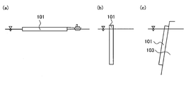
- FIG. 8 is a view showing a method of installing the temporary closing structure 101 by the floating method.
- 8 (a) shows a step of towing the temporary closing structure 101
- FIG. 8 (b) shows a step of making the temporary closing structure 101 in a substantially vertical state
- FIG. FIG. 10 is a view showing a process of installing the temporary closing structure 101 on the levee 103.
- the floating method after temporarily assembling the temporary closing structure 101 on land, as shown in FIG. 8A, the temporary closing structure 101 floats on the water surface and is towed in a laid state. Then, water is poured into the temporary closing structure 101, and floats on the water surface in a substantially vertical state as shown in FIG. 8 (b). Thereafter, as shown in FIG. 8C, the temporary closing structure 101 is installed on the levee 103 (see, for example, Patent Document 1).
- the present invention has been made in view of the above-mentioned problems, and it is an object of the present invention to provide a floating body in which a temporary closing structure can be assembled without performing diving work under deep water conditions in a limited space on water. It is to provide a construction method of a temporary cofferdam.
- the present invention is a construction method of a floating type temporary closing structure using a temporary closing structure which is constituted by a bottom portion and a side wall portion consisting of a plurality of blocks and a part of side surfaces are opened.
- the lower block is connected above the bottom with the bottom suspended above the water surface, and the upper block is connected above the lower block in step (a) of sinking to a predetermined depth.
- the step of forming the temporary closing structure by repeating the operation of sinking to a predetermined depth a plurality of times to form the temporary closing structure, and the temporary closing structure being floated and towed in a standing state, and installed on the wall surface of the levee
- It is a construction method of a floating type temporary cofferdam characterized by comprising a process (c) and a process (d) which drains the inside surrounded by the temporary closing structure and the wall surface of the dike, and (d). .
- the operation of connecting the upper block to the upper side of the lower block and sinking to a predetermined depth is repeated a plurality of times to form the temporary closing structure. Therefore, it is possible to assemble the temporary closing structure in a limited space above the water without performing a diving operation under deep water conditions.
- connection structure for connecting the blocks in such a manner as to allow a predetermined amount of movement in the horizontal direction is provided at the butt portion of the lower block and the upper block.
- the connection structure is formed, for example, by connecting a first connection metal provided in the lower block and a second connection metal provided in the upper block with a bolt, and the first connection metal is formed. And the second connecting piece are spaced apart from each other, and the bolt is deformable between the first connecting piece and the second connecting piece.
- Each block which comprises a temporary closing structure can be made to follow the non-land of a wall surface, and it can be installed so that waterproofness may not be impaired.
- a watertight rubber provided along the edge of one block and a rubber abutment provided along the edge of the other block It is desirable that a water blocking structure formed by contacting while deforming is provided. Thereby, the waterproofness of the butted portion of the lower block and the upper block is reliably ensured.
- the top end of the temporary closing structure may be provided with a flap type movable lid.
- a step (e) of installing a U-shaped rubber gasket in a portion of the temporary closing structure facing the wall surface of the bank is further provided. It is desirable to have it. As a result, since the water blocking member can be continuously installed on the door contact surface of the temporary closing structure, waterproofness between the temporary closing structure and the bank body is reliably ensured.
- the construction method of the floating type temporary crusher which can assemble a temporary shutoff structure in a limited space on water without performing a diving operation in deep water conditions can be provided.
- FIG. 1A is a front view of the temporary closing structure 1
- FIG. 1B is a view seen from the direction of arrow A in FIG. 1A
- 1 (c) is a view as seen from the direction of arrow C in FIG. 1 (b)
- FIG. 1 (d) is a cross-sectional view taken along the line BB in FIG. 1 (a).
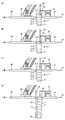
- 2 (a) to 2 (d) are diagrams showing an assembly process of the temporary closing structure 1 It is a figure which shows the detail of the connection structure 11 and the water stop structure 13
- FIG. 3 (a) is a figure which shows the state before connection of a block
- FIG.3 (b) is a figure which shows the state after connection of a block.
- FIG. 1A is a front view of the temporary closing structure 1
- FIG. 1B is a view seen from the direction of arrow A in FIG. 1A
- 1 (c) is a view as seen from the direction of arrow C in FIG. 1 (b)
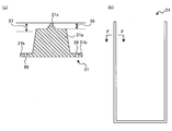
- FIG. 4A is a cross-sectional view of the rubber gasket 21, and FIG. 4B is an elevation view of the rubber gasket 21.
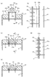
- FIG. 5A is a view showing a step of aligning the rubber gasket 21.
- FIG. 5B is a cross-sectional view taken along the line HH of FIG. 5A.
- 5 (c) shows a state in which the rubber gasket 21 is attached
- FIG. 5 (d) is a cross-sectional view taken along the line II of FIG. 5 (c)
- FIG. 5 (e) is FIG. The enlarged view of the range G shown to d).
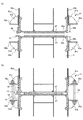
- 6 (a) is an elevation view of the temporary closing structure 2
- FIG. 6 (b) is a side view of the temporary closing structure 2
- FIG. 6 (c) is a view showing an outline of the temporary closing structure 2.
- FIG. 2 is a horizontal sectional view of a temporary shutoff structure 2;
- FIG. 7 (a) is an enlarged view of the range J shown in FIG. 6 (a), and
- FIG. 7 (b) is an enlarged view of the range K shown in FIG. 6 (b).
- Fig. 7 (c) is an enlarged view of a range M shown in Fig. 6 (c).
- FIG. 8 (a) is a figure which shows the process of towing the conventional temporary closing structure 101
- FIG.8 (b) is the conventional
- FIG. 8C is a view showing a step of installing the conventional temporary closing structure 101 on the levee 103, showing a step of making the temporary closing structure 101 of the second embodiment substantially vertical.
- FIG. 1 is a view showing an outline of a temporary closing structure 1.
- FIG. 1A is a front view of the temporary closing structure 1.
- FIG. 1 (b) is a side view of the temporary closing structure 1.
- FIG. 1 (b) is a view seen from the direction of arrow A shown in FIG. 1 (a).
- FIG. 1 (c) is a rear view of the temporary closing structure 1.
- FIG. 1 (c) is a view seen from the direction of arrow C shown in FIG. 1 (b).
- FIG. 1D is a horizontal cross-sectional view of the block 3 constituting the temporary closing structure 1.
- FIG. 1 (d) is a cross-sectional view along arrow BB shown in FIG. 1 (a).
- the temporary closing structure 1 includes a bottom 5, a side wall 7, a movable lid 6, and the like.
- the side wall 7 comprises a plurality of blocks 3 stacked one on top of the other.
- a water blocking structure 13 is formed at the abutment portion between the lower block 3 and the upper block 3. Details of the water blocking structure 13 will be described later.
- the lower block 3 and the upper block 3 are connected by a connecting structure 11 which is connected to allow movement of a predetermined amount in the horizontal direction. Details of the connection structure 11 will be described later.
- the temporary closing structure 1 has a shape in which a part of the side surface is opened.
- the block 3 which comprises the temporary closing structure 1 is provided with the some partition 25 inside.
- the interior of block 3 is divided by partitions 25 into a plurality of spaces 23.
- a water supply and drainage valve 9 is provided in the block 3 of the predetermined number of stages in the lower stage.
- the pouring and draining valve 9 is disposed in each space 23 of the block 3.
- the movable lid 6 is provided at the top end 18 of the temporary closing structure 1.
- the movable cover 6 has a rotational support near the end 17 of the top end 18.
- the movable lid 6 is a flap type lid and opens and closes as indicated by an arrow E.
- the end portion 17 of the temporary closing structure 1 which is a portion facing the wall surface of the levee, includes a wood 19 and a U-shaped rubber gasket 21.
- a water blocking structure 15 is formed. Details of the water blocking structure 15 will be described later.
- FIG. 2 is a view showing a method of assembling the temporary closing structure 1.
- the temporary shutoff structure 1 shown in FIG. 1 is assembled, for example, between a barge 27 and a barge 29 floating on a water surface 37, as shown in FIG.
- a structure support rack 31 having a chain block 33 is installed on the barge 27.
- a crawler crane 35 is installed on the base ship 29.
- the lowermost block 3-1 is connected above the bottom 5 and is sunk to a predetermined depth. Thereafter, the operation of connecting the upper block 3 above the lower block 3 and sinking the block 3 to a predetermined depth is repeated a plurality of times until the connection of the n stages of the blocks 3 is completed.
- FIG. 2 (a) to FIG. 2 (c) show the process of connecting block 3-4 to block 3-3.
- a method of connecting the blocks 3 will be described with reference to FIGS. 2A to 2C and taking the blocks 3-3 and 3-4 as examples.
- the upper block 3-4 is suspended using the crawler crane 35 above the lower block 3-3 suspended by the chain block 33.
- the lower block 3-3 and the upper block 3-4 are connected by the connecting structure 11 (FIG. 1).
- the water blocking structure 13 (FIG. 1) shuts off between the lower block 3-3 and the upper block 3-4.
- the chain block 33 and the crawler crane 35 are simultaneously lowered. . Then, the temporary closing structure 1 being assembled is sunk to a predetermined depth (a position where the self weight including the ballast water weight and the buoyancy are suspended).
- ballast water is injected into the predetermined space 23 (FIG. 1 (d)) in the lower blocks 3-1, 3-2.
- the block 33 and the crawler crane 35 are simultaneously lowered.
- the temporary closing structure 1 being assembled is sunk to a predetermined depth (a position where the self weight including the ballast water weight and the buoyancy are suspended), and the chain block 33 is changed from the block 3-3 to the block 3-4.
- FIG. 3 is a view showing the details of the connection structure 11 and the water stop structure 13. Below, the connection structure 11 which connects the lower block 3 and the upper block 3 and the water blocking structure 13 between the lower block 3 and the upper block 3 will be described with reference to FIG.
- FIG. 3 (a) is a view showing a state before the connection of the butt portions of the upper block 3 and the lower block 3.
- the upper block 3 is formed by connecting metal 41a on the outer side 43a and the inner side 43b of the temporary closing structure 1 at a predetermined distance 39a from the lower surface 45a. It is fixed. Further, in the lower block 3, the connection metal 41 b is fixed to the lower side at a predetermined distance 39 b from the upper surface 45 b.
- the connecting hardware 41a, 41b comprises a horizontal connecting plate 42a and a vertical rib 42b.
- a bearing plate 47 is provided on the lower surface 45a and the upper surface 45b of the upper block 3 and the lower block 3, respectively.
- the upper block 3 is provided with a water-tight rubber 49 having a P-type cross section on the entire length of the lower edge of the outer side surface 43 a of the temporary closing structure 1.
- the watertight rubber 49 is arranged such that the circular portion of the P-type protrudes by a small amount from the lower surface 45a of the block 3 in the upper stage.
- the lower block 3 is provided with a rubber contact portion 51 on the entire length of the upper edge of the side surface 43a.
- FIG. 3 (b) is a view showing a state after connection of the butt parts of the block 3 in the upper stage and the block 3 in the lower stage.
- the connecting structure 11 passes the bolt 53 through the first connecting metal 41b provided in the lower block 3 and the second connecting metal 41a provided in the upper block 3 And the bolt 53 is fixed at the position of the connecting plate 42a.
- the first connecting metal 41b and the second connecting metal 41a are arranged at a predetermined distance, and the bolt 53 is between the first connecting metal 41b and the second connecting metal 41a. It is deformable. As a result, the lower block 3 and the upper block 3 are allowed to move by a predetermined amount in the horizontal direction.
- the water blocking structure 13 is formed by bringing a circular portion of the P-type watertight rubber 49 into contact with the rubber contact portion 51 while deforming it.
- the bearing plate 47 of the lower surface 45 a of the upper block 3 and the bearing plate 47 of the upper surface 45 b of the lower block 3 are in contact with each other.
- FIG. 2D is a view showing a process of attaching the rubber gasket 21 to the temporary closing structure 1 after the connection work of the blocks 3 is completed.
- FIG. 4 is a view showing an outline of the rubber gasket 21, and
- FIG. 5 is a view showing a method of attaching the rubber gasket 21. As shown in FIG. The outline of the rubber gasket 21 and the method of attaching it to the temporary shut-off structure 1 will be described below with reference to FIGS. 2 (d), 4 and 5.
- FIG. 1 The outline of the rubber gasket 21 and the method of attaching it to the temporary shut-off structure 1 will be described below with reference to FIGS. 2 (d), 4 and 5.
- FIG. 4A is a cross-sectional view of the rubber gasket 21, and FIG. 4B is an elevation view of the rubber gasket 21.
- FIG. 4 (a) is a cross-sectional view taken along the arrow FF shown in FIG. 4 (b).
- the rubber gasket 21 is U-shaped.
- the rubber gasket 21 consists of the main body 21a and the fixing
- the main body 21a has a single nose 21c at the center of the upper surface.
- the compression amount 57 of the main body 21a is the nose height 55 + ⁇ of the nose 21c, and desirably about 50 to 60 mm.
- the fixing portion 21 b is provided so as to protrude in the direction of both sides from the lower surface of the main body 21 a.
- the fixing portion 21 b has a hole 59.
- FIG. 5 (a) and 5 (b) show the process of aligning the rubber gasket 21.
- FIG. FIG. 5 (b) is a cross-sectional view taken along arrows HH shown in FIG. 5 (a).
- 5 (c) to 5 (e) are views showing a state in which the rubber gasket 21 is attached.
- FIG. 5 (d) is a cross-sectional view taken along arrow II shown in FIG. 5 (c).
- FIG.5 (e) is an enlarged view of the range G shown in FIG.1 (d).
- FIG. 2 (d) When assembling the temporary closing structure 1, after forming all the side walls 7 by connecting all the blocks 3 by the method described with FIG. 2 (a) to FIG. 2 (c) as an example, FIG. 2 (d)
- the rubber gasket 21 is suspended in water using a crawler crane 35 as shown in FIG.
- the rubber gasket 21 is suspended on the end 17 side of the temporary closing structure 1. It is desirable to attach a balance weight 91 to the lower end of the rubber gasket 21 in order to maintain the shape and posture of the rubber gasket 21.
- the wood 19 is disposed at the end 17 of the temporary closing structure 1. As shown in FIG. 5A, the wood 19 is disposed on both sides of the end 17 of each block 3. Long bolts 61 are disposed between the woods 19. Further, as shown in FIG. 5 (b), short bolts 63 are also arranged. The long bolt 61 and the short bolt 63 are fixed to the block 3.
- the rubber gasket 21 suspended in water as shown in FIG. 2 (d) is positioned so that the hole 59 overlaps the tip of the long bolt 61, as shown in FIGS. 5 (a) and 5 (b). . Then, the long bolt 61 is inserted into the hole 59, and as shown in FIG. 5C, the rubber gasket 21 is attached between the woods 19 of each block 3. The wood 19 is thinner than the rubber gasket 21.
- the long bolt 61 of the block 3 is inserted into the hole 59 of the rubber gasket 21, as shown in FIGS. 5 (d) and 5 (e)
- the positions of the remaining holes of the rubber gasket 21 and the short bolts 63 of the block 3 are obtained.
- the fitting and the insertion of the short bolts 63 into the remaining holes take place simultaneously. Thereby, the rubber gasket 21 can be easily attached to the temporary closing structure 1.
- FIG. 6 is a view showing an outline of the temporary shutoff structure 2.
- 6 (a) is an elevation view of the temporary closing structure 2
- FIG. 6 (b) is a side view of the temporary closing structure 2
- FIG. 6 (c) is a horizontal sectional view of the temporary closing structure 2.
- FIG. 6 (c) is a cross-sectional view taken along arrow L--L shown in FIG. 6 (b).
- FIG. 7 is a view showing the details of the temporary shutoff structure 2.
- FIG. 7A is a front view of the uplift prevention mechanism 65.
- FIG. Fig.7 (a) is an enlarged view of the range J shown to Fig.6 (a).
- FIG. 7 (b) is a side view of the uplifting prevention mechanism 65.
- FIG. 7 (b) is an enlarged view of the range K shown in FIG. 6 (b).
- FIG. 7C is a horizontal sectional view around the stopper 85.
- FIG. FIG.7 (c) is an enlarged view of the range M shown in FIG.6 (c).
- the temporary closing structure 2 is formed by draining the inside 89 surrounded by the temporary closing structure 1 and the wall surface 68 of the bank 69 after the temporary closing structure 1 is installed in the bank 69.
- a door stop 67 is installed in a frame shape on the wall surface 68 of the dam 69.
- the door stop 67 is fixed to the wall surface 68 of the dam 69 by using the anchor metal 87a and the anchor metal 87b, as shown in FIG. 7 (c).
- the temporary closing structure 1 assembled in each process shown in FIG. 2 is floated in a standing state, and is towed near the planned installation position of the dam 69.
- the edge part 17 of the temporary closing structure 1 is arrange
- an anti-lifting mechanism 65 is installed between the top end 18 of the temporary closing structure 1 and the wall surface 68 of the dam 69.
- a stopper 85 is installed between the side wall 7 of the temporary closing structure 1 and the wall surface 68 of the dam 69.
- the floating preventing mechanism 65 is formed by the floating preventing anchor 73, the flange portion 71, the sliding plate 77, the hanging rod 75, and the like.
- the anti-lifting anchor 73 is a plate-like member having a grid-like reinforcing material 83.
- the anti-lifting anchor 73 is fixed to the wall surface 68 of the dam 69 by an anchor bolt 79.
- the flange portion 71 is disposed between the lower end surface 81 of the anti-lifting anchor 73 and the top end 18 of the temporary closing structure 1.
- the ridge portion 71 is disposed along the wall surface 68 of the dam 69, and the formation length 76 of the ridge portion 71 from the wall surface 68 is a length 80 from the wall surface 68 to the floating core 78 of the temporary closing structure 1 (see FIG. It shall be shorter than 6 (b).
- the sliding plate 77 is provided between the flange portion 71 and the top end 18 of the temporary closing structure 1.
- the ridge portion 71 may be in contact with the top end 18 of the temporary closing structure 1 via the sliding plate 77, and does not have to be connected to the top end 18.
- the hanging rod 75 connects the top end 18 of the temporary closing structure 1 and the anti-lifting anchor 73.
- the end of the suspension rod 75 on the side of the anti-lifting anchor 73 is connected to, for example, the reinforcing member 83.
- the brim portion 71 supports the buoyancy of the temporary closing structure 1, and prevents lifting.
- the formation length 76 of the flange portion 71 is shorter than the length 80 from the wall surface 68 to the floating core 78 of the temporary closing structure 1.
- the sliding plate 77 enables horizontal movement of the uppermost block 3 of the temporary closing structure 1.
- the suspension rod 75 prevents the temporary closing structure 1 from sinking when the water level drops abnormally.
- one end of the stopper 85 is connected to the inner side surface 43 a of the side wall 7 of the temporary closing structure 1.
- the stopper 85 is connected at the other end to the anchor metal 87 a of the door stop 67.
- the stopper 85 prevents the temporary closing structure 1 from separating from the levee body 69 by earthquake motion or the like.
- the rubber gasket 21 compressed and deformed to a thickness comparable to that of the wood 19 and 19 makes contact with the door contact 67.
- the water blocking structure 15 is formed.
- the wood 19 prevents positional deviation of the temporary closing structure 1 by friction with the door stop 67.
- the rubber gasket 21 prevents the movement of water between the inside and the outside of the temporary closing structure 1.
- the movable cover 6 is installed on the top end 18. Then, the inside 89 surrounded by the temporary closing structure 1 and the wall surface 68 of the dam 69 is drained to complete the temporary closing.
- the temporary closing structure 1 formed by repeating the operation of connecting the upper block 3 above the lower block 3 and sinking to a predetermined depth a plurality of times is erected. It floats and is towed and installed on the wall 68 of the dam 69. Thereby, temporary closing structure 1 can be assembled in a limited space on water without performing diving work under deep water conditions, and temporary closing structure 2 can be formed.
- a rubber gasket 21 having a predetermined compression margin is installed at the end 17 opposed to the wall surface 68 of the dam 69, as a water blocking member, according to the end 17 and having a U shape. . Even when there is a gap in the door stop 67, the water gasket 15 between the end 17 of the temporary shut-off structure 1 and the door lock 67 can be assured by compressing and deforming the rubber gasket 21 while following the gap. It can be
- the watertight rubber 49 provided along the lower edge of the upper block 3 and the upper edge of the lower block 3 are provided at the abutment portion between the lower block 3 and the upper block 3
- a water blocking structure 13 is provided, in which the rubber contact portion 51 is brought into contact with the watertight rubber 49 while being deformed.
- a flap type movable lid 6 is provided at the top end 18. In this way, it is possible to prepare for rising of the dam water level due to abnormal water discharge.
- the floating prevention mechanism 65 In the temporary closing structure 2, by installing the floating prevention mechanism 65, floating of the temporary closing structure 1 can be prevented at the time of rising of the water level by the flange portion 71 of the floating prevention mechanism 65.
- the sliding plate 77 enables horizontal movement of the uppermost block 3 of the temporary closing structure 1.
- the suspension rod 75 can prevent the temporary closing structure 1 from sinking when the water level is lowered.
- the horizontal cross-sectional shape of the temporary closing structure 1 is not restricted to what was shown in FIG.1 (d).
- the temporary closing structure 1 may be formed of a bottom portion and a side wall portion formed of a plurality of blocks, and it is sufficient that a part of the side surface is opened.
- not the wood 19 but steel may be disposed on both sides of the rubber gasket 21 of the water blocking structure 15.
- a hanging rope may be used instead of the hanging rod 75 as a hanging member.
Landscapes
- Engineering & Computer Science (AREA)
- Life Sciences & Earth Sciences (AREA)
- General Life Sciences & Earth Sciences (AREA)
- Mining & Mineral Resources (AREA)
- Paleontology (AREA)
- Civil Engineering (AREA)
- General Engineering & Computer Science (AREA)
- Structural Engineering (AREA)
- Barrages (AREA)
- Revetment (AREA)
Abstract
底部5を水面上に浮遊させた状態で上方に最下段のブロック3を連結し、所定の深度まで沈下させる。その後、下段のブロック3の上方に上段のブロック3を、互いに水平方向の所定量の移動を許容する連結構造11を用いて連結し、所定の深度まで沈下させる作業を複数回繰り返す。全てのブロック3の連結が完了した後、仮締切り構造体1の端部17にU字状のゴムガスケット21を設置して仮締切り構造体1を形成する。次に、仮締切り構造体1を起立した状態で浮遊させて曳航し、堤体69の壁面68に設置する。仮締切り構造体1の天端18には、フラップ式の可動蓋6を設ける。その後、仮締切り構造体1と堤体69の壁面68とに囲まれた内部を排水する。
Description
本発明は、底部および複数のブロックからなる側壁部により構成され一部の側面が開放された仮締切り構造体を用いた浮体式仮締切り工の施工方法に関する。
従来、ダム等の水中の対象物において、水中側からの工事を行う場合、対象物に仮締切り構造体を設置し、対象物と仮締切り構造体とに囲まれた部分を排水して作業空間を形成することがある。台座コンクリート式工法では、仮締切り据付位置において、仮締切り構造体の扉体を一段ずつ吊り込んで連結することにより、所定の位置に仮締切り構造体を設置する。
図8は、浮体式工法による仮締切り構造体101の設置方法を示す図である。図8(a)は、仮締切り構造体101を曳航する工程を示す図、図8(b)は、仮締切り構造体101を略垂直の状態にする工程を示す図、図8(c)は、仮締切り構造体101を堤体103に設置する工程を示す図である。浮体式工法では、仮締切り構造体101を陸上で事前に組み立てた後、図8(a)に示すように、寝かせた状態で水面に浮かせて曳航する。そして、仮締切り構造体101内に注水し、図8(b)に示すように、略垂直な状態で水面に浮かせる。その後、図8(c)に示すように、堤体103に仮締切り構造体101を設置する(例えば、特許文献1参照)。
しかしながら、浮体式工法において、仮締切り構造体を陸上で事前に組み立てるための作業空間が確保できない場合があった。
本発明は、前述した問題点に鑑みてなされたもので、その目的とすることは、水上の限られた空間で、大水深条件での潜水作業を行うことなく仮締切り構造体を組み立てられる浮体式仮締切り工の施工方法を提供することである。
前述した目的を達成するために、本発明は、底部および複数のブロックからなる側壁部により構成され一部の側面が開放された仮締切り構造体を用いた浮体式仮締切り工の施工方法であって、底部を水面上に浮遊させた状態で、前記底部の上方に最下段のブロックを連結し、所定の深度まで沈下させる工程(a)と、下段のブロックの上方に上段のブロックを連結して所定の深度まで沈下させる作業を複数回繰り返して仮締切り構造体を形成する工程(b)と、前記仮締切り構造体を、起立した状態で浮遊させて曳航し、堤体の壁面に設置する工程(c)と、前記仮締切り構造体と前記堤体の壁面とに囲まれた内部を排水する工程(d)と、を具備することを特徴とする浮体式仮締切り工の施工方法である。
本発明では、下段のブロックの上方に上段のブロックを連結して所定の深度まで沈下させる作業を複数回繰り返して仮締切り構造体を形成する。そのため、水上の限られた空間で、大水深条件での潜水作業を行うことなく仮締切り構造体を組み立てることができる。
前記下段のブロックと前記上段のブロックとの突合せ部分には、前記ブロック同士を、水平方向の所定量の移動を許容するように連結する連結構造が設けられることが望ましい。前記連結構造は、例えば、前記下段のブロックに設けられた第1の連結金物と前記上段のブロックに設けられた第2の連結金物とをボルトにより連結して形成され、前記第1の連結金物と前記第2の連結金物が所定の間隔をおいて配置され、前記ボルトが、前記第1の連結金物と前記第2の連結金物との間で変形可能である。
下段のブロックと上段のブロックとを、水平方向の所定量の移動を許容するように連結することにより、堤体の壁面に不陸がある場合に、仮締切り構造体と堤体との間の止水性を損なわないよう、仮締切り構造体を構成する各ブロックを壁面の不陸に追随させて設置することができる。
前記下段のブロックと前記上段のブロックとの突合せ部分には、一方のブロックの縁に沿って設けられた水密ゴムと他方のブロックの縁に沿って設けられたゴム当たり部とを、前記水密ゴムを変形させつつ接触させて形成される止水構造が設けられることが望ましい。
これにより、下段のブロックと上段のブロックとの突合せ部分の止水性が確実に確保される。
これにより、下段のブロックと上段のブロックとの突合せ部分の止水性が確実に確保される。
前記仮締切り構造体の天端には、フラップ式の可動蓋を設けてもよい。
可動蓋を設けることにより、異常出水によるダム水位上昇に備えることができる。
可動蓋を設けることにより、異常出水によるダム水位上昇に備えることができる。
前記工程(b)と前記工程(c)との間には、前記仮締切り構造体の、前記堤体の壁面と対向する部分に、U字状のゴムガスケットを設置する工程(e)をさらに具備することが望ましい。
これにより、仮締切り構造体の戸当たり面に、止水部材を連続して設置することができるため、仮締切り構造体と堤体との間の止水性が確実に確保される。
これにより、仮締切り構造体の戸当たり面に、止水部材を連続して設置することができるため、仮締切り構造体と堤体との間の止水性が確実に確保される。
本発明によれば、水上の限られた空間で、大水深条件での潜水作業を行うことなく仮締切り構造体を組み立てられる浮体式仮締切り工の施工方法を提供できる。
以下、図面に基づいて、本発明の実施の形態について詳細に説明する。図1は、仮締切り構造体1の概要を示す図である。図1(a)は、仮締切り構造体1の正面図である。図1(b)は、仮締切り構造体1の側面図である。図1(b)は、図1(a)に示す矢印Aの方向から見た図である。図1(c)は、仮締切り構造体1の背面図である。図1(c)は、図1(b)に示す矢印Cの方向から見た図である。図1(d)は、仮締切り構造体1を構成するブロック3の水平断面図である。図1(d)は、図1(a)に示す矢印B-Bによる断面図である。
図1(a)、図1(b)に示すように、仮締切り構造体1は、底部5、側壁部7、可動蓋6等で構成される。側壁部7は、上下に積み重ねられた複数のブロック3からなる。下段のブロック3と上段のブロック3との突合せ部分には、止水構造13が形成される。止水構造13の詳細については後述する。また、下段のブロック3と上段のブロック3とは、水平方向の所定量の移動を許容するように連結する連結構造11によって連結される。連結構造11の詳細については後述する。
図1(d)に示すように、仮締切り構造体1は、一部の側面が開放された形状である。仮締切り構造体1を構成するブロック3は、内部に複数の仕切り25が設けられる。ブロック3の内部は、仕切り25によって、複数の空間23に分割される。
図1(a)、図1(b)に示すように、仮締切り構造体1を構成するブロック3のうち、下段の所定の段数のブロック3には、注排水バルブ9が設けられる。注排水バルブ9は、ブロック3の空間23毎に配置される。
図1(a)、図1(b)に示すように、可動蓋6は、仮締切り構造体1の天端18に設けられる。可動蓋6は、天端18の端部17付近に回転支持部が配置される。可動蓋6はフラップ式の蓋であり、矢印Eに示すように開閉する。
図1(c)、図1(d)に示すように、仮締切り構造体1の、堤体の壁面と対向する部分である端部17には、木材19とU字状のゴムガスケット21とからなる止水構造15が形成される。止水構造15の詳細については後述する。
図2は、仮締切り構造体1の組み立て方法を示す図である。図1に示す仮締切り構造体1は、図2に示すように、例えば、水面37に浮かんだ台船27、台船29の間にて組み立てられる。台船27上には、チェーンブロック33を有する構造体支持架台31が設置される。台船29上には、クローラクレーン35が設置される。
仮締切り構造体1を組み立てるには、まず、底部5を水面37上に浮遊させた状態で、底部5の上方に最下段のブロック3-1を連結し、所定の深度まで沈下させる。その後、下段のブロック3の上方に上段のブロック3を連結して所定の深度まで沈下させる作業を、n段のブロック3の連結終了まで複数回繰り返す。
図2(a)から図2(c)は、ブロック3-3にブロック3-4を連結する工程を示す。以下に、図2(a)から図2(c)を用い、ブロック3-3とブロック3-4とを例として、ブロック3同士の連結方法について説明する。図2(a)に示す工程では、チェーンブロック33で吊り下げた下段のブロック3-3の上方に、クローラクレーン35を用いて上段のブロック3-4を吊り下げる。そして、下段のブロック3-3と上段のブロック3-4とを、連結構造11(図1)により連結する。下段のブロック3-3と上段のブロック3-4との間は、止水構造13(図1)により止水される。
図2(a)に示す工程で下段のブロック3-3と上段のブロック3-4とを連結した後、図2(b)に示す工程では、チェーンブロック33とクローラクレーン35とを同時に巻き下げる。そして、組立中の仮締切り構造体1を所定の深度(バラスト水重量を含む自重と浮力とが吊り合う位置)まで沈下させる。
図2(c)に示す工程では、下方のブロック3-1、3-2…内の所定の空間23(図1(d))に、注排水バルブ9を介してバラスト水を注入し、チェーンブロック33とクローラクレーン35とを同時に巻き下げる。そして、組立中の仮締切り構造体1を所定の深度(バラスト水重量を含む自重と浮力とが吊り合う位置)まで沈下させ、チェーンブロック33をブロック3-3からブロック3-4に付け替える。
図3は、連結構造11および止水構造13の詳細を示す図である。以下に、図3を用いて、下段のブロック3と上段のブロック3を連結する連結構造11、下段のブロック3と上段のブロック3との間の止水構造13について説明する。
図3(a)は、上段のブロック3と下段のブロック3との突合せ部分の連結前の状態を示す図である。図3(a)に示すように、上段のブロック3は、仮締切り構造体1の外側の側面43aおよび内側の側面43bの、下面45aから所定の距離39aをおいた上方に、連結金物41aが固定される。また、下段のブロック3は、上面45bから所定の距離39bをおいた下方に、連結金物41bが固定される。連結金物41a、41bは、水平方向の連結板42aと垂直方向のリブ42bとからなる。
図3(a)に示すように、上段のブロック3と下段のブロック3は、下面45a、上面45bに、それぞれ支圧板47が設けられる。上段のブロック3は、仮締切り構造体1の外側の側面43aの下縁部の全長に、断面がP型の水密ゴム49が設けられる。水密ゴム49は、上段のブロック3の下面45aからP型の円形部分が少量だけ突出するように配置される。下段のブロック3は、側面43aの上縁部の全長に、ゴム当たり部51が設けられる。
図3(b)は、上段のブロック3と下段のブロック3との突合せ部分の連結後の状態を示す図である。図3(b)に示すように、連結構造11は、下段のブロック3に設けられた第1の連結金物41bと上段のブロック3に設けられた第2の連結金物41aとにボルト53を挿通し、ボルト53を連結板42aの位置で固定して形成される。連結構造11では、第1の連結金物41bと第2の連結金物41aとが所定の間隔をおいて配置され、ボルト53が、第1の連結金物41bと第2の連結金物41aとの間で変形可能である。これにより、下段のブロック3と上段のブロック3とは、互いに水平方向の所定量の移動が許容される。
図3(b)に示すように、止水構造13は、P型の水密ゴム49の円形部分をゴム当たり部51に変形させつつ接触させて形成される。上段のブロック3の下面45aの支圧板47と、下段のブロック3の上面45bの支圧板47とは、接触する。
図2(d)は、ブロック3の連結作業を終えた仮締切り構造体1に、ゴムガスケット21を取り付ける工程を示す図である。図4は、ゴムガスケット21の概要を示す図、図5は、ゴムガスケット21の取付け方法を示す図である。以下に、図2(d)、図4、図5を用いて、ゴムガスケット21の概要および仮締切り構造体1への取付け方法について説明する。
図4(a)は、ゴムガスケット21の断面図、図4(b)は、ゴムガスケット21の立面図である。図4(a)は、図4(b)に示す矢印F-Fによる断面図である。図4(b)に示すように、ゴムガスケット21は、U字型である。図4(a)に示すように、ゴムガスケット21は、本体21a、固定部21bからなる。本体21aは、上面の中央に1条のノーズ21cを有する。本体21aの圧縮量57は、ノーズ21cのノーズ高55+αであり、50~60mm程度が望ましい。固定部21bは、本体21aの下面から両側部方向に突出して設けられる。固定部21bは、孔59を有する。
図5(a)および図5(b)は、ゴムガスケット21の位置合わせをする工程を示す。図5(b)は、図5(a)に示す矢印H-Hによる断面図である。図5(c)から図5(e)は、ゴムガスケット21を取り付けた状態を示す図である。図5(d)は、図5(c)に示す矢印I-Iによる断面図である。図5(e)は、図1(d)に示す範囲Gの拡大図である。
仮締切り構造体1を組み立てる際には、図2(a)から図2(c)を例として説明した方法で全てのブロック3を連結して側壁部7を形成した後、図2(d)に示すように、クローラクレーン35を用いてゴムガスケット21を水中に吊り下げる。ゴムガスケット21は、仮締切り構造体1の端部17側に吊り下げられる。ゴムガスケット21の下端には、ゴムガスケット21の形状および姿勢を維持するために、バランスウェイト91を取り付けることが望ましい。
前述したように、仮締切り構造体1の端部17には、木材19が配置される。図5(a)に示すように、木材19は、各ブロック3の端部17の両側部に配置される。木材19同士の間には、長ボルト61が配置される。また、図5(b)に示すように、短ボルト63も配置される。長ボルト61および短ボルト63は、ブロック3に固定される。
図2(d)に示すように水中に吊り下げたゴムガスケット21は、図5(a)、図5(b)に示すように、孔59が長ボルト61の先端に重なるように位置合わせする。そして、長ボルト61を孔59に挿入し、図5(c)に示すように、ゴムガスケット21を各ブロック3の木材19同士の間に取り付ける。木材19は、ゴムガスケット21よりも厚さが薄いものとする。ゴムガスケット21の孔59にブロック3の長ボルト61を挿入すると、図5(d)、図5(e)に示すように、ゴムガスケット21の残りの孔とブロック3の短ボルト63との位置合わせおよび残りの孔への短ボルト63の挿入が同時に行われる。これにより、仮締切り構造体1にゴムガスケット21を容易に取り付けることができる。
図6は、仮締切り構造2の概要を示す図である。図6(a)は、仮締切り構造2の立面図、図6(b)は、仮締切り構造2の側面図、図6(c)は、仮締切り構造2の水平断面図である。図6(c)は、図6(b)に示す矢印L-Lによる断面図である。
図7は、仮締切り構造2の詳細を示す図である。図7(a)は、浮き上がり防止機構65の正面図である。図7(a)は、図6(a)に示す範囲Jの拡大図である。図7(b)は、浮き上がり防止機構65の側面図である。図7(b)は、図6(b)に示す範囲Kの拡大図である。図7(c)は、ストッパ85付近の水平断面図である。図7(c)は、図6(c)に示す範囲Mの拡大図である。
仮締切り構造2は、堤体69に仮締切り構造体1を設置した後、仮締切り構造体1と堤体69の壁面68とに囲まれた内部89を排水して形成される。図6に示すように、仮締切り構造2では、堤体69の壁面68に戸当たり67が額縁状に設置されている。戸当たり67は、図7(c)に示すように、アンカ金物87a、アンカ金物87bを用いて堤体69の壁面68に固定される。なお、堤体69の壁面68への戸当たり67の設置は、仮締切り構造体1の組み立てと並行して行うのが望ましい。
堤体69に仮締切り構造体1を設置するには、図2に示す各工程により組み立てた仮締切り構造体1を、起立した状態で浮遊させて、堤体69の設置予定位置付近まで曳航する。そして、図6(b)に示すように、仮締切り構造体1の端部17を、堤体69の壁面68の戸当たり67に合わせて配置する。図6(a)、図6(b)に示すように、仮締切り構造体1の天端18と堤体69の壁面68との間には、浮き上がり防止機構65を設置する。図6(c)に示すように、仮締切り構造体1の側壁部7と堤体69の壁面68との間には、ストッパ85を設置する。
図7(a)、図7(b)に示すように、浮き上がり防止機構65は、浮上り防止アンカ73、沓部71、摺動板77、吊下げロッド75等で形成される。浮上り防止アンカ73は、格子状の補強材83を有する板状部材である。浮上り防止アンカ73は、アンカボルト79によって堤体69の壁面68に固定される。沓部71は、浮上り防止アンカ73の下端面81と仮締切り構造体1の天端18との間に配置される。沓部71は、堤体69の壁面68に沿って配置され、壁面68からの沓部71の形成長さ76は、壁面68から仮締切り構造体1の浮心78までの長さ80(図6(b))よりも短いものとする。摺動板77は、沓部71と仮締切り構造体1の天端18との間に設けられる。沓部71は、摺動板77を介して仮締切り構造体1の天端18に接触していればよく、天端18に連結する必要はない。吊下げロッド75は、仮締切り構造体1の天端18と浮上り防止アンカ73とを連結する。吊下げロッド75の浮上り防止アンカ73側の端部は、例えば、補強材83に連結される。
浮き上がり防止機構65では、沓部71が、仮締切り構造体1の浮力を支持し、浮き上がりを防止する。上述したように、沓部71の形成長さ76は壁面68から仮締切り構造体1の浮心78までの長さ80よりも短い。これにより仮締切り構造体1に生じる回転モーメントは水圧によって打ち消されるため、仮締切り構造体1が浮き上がる(壁体から離れる)ことはない。摺動板77は、仮締切り構造体1の最上段のブロック3の水平移動を可能とする。吊下げロッド75は、異常に水位が下がった場合に、仮締切り構造体1の沈下を防止する。
図7(c)に示すように、ストッパ85は、一端が、仮締切り構造体1の側壁部7の内側の側面43aに連結される。ストッパ85は、他端が、戸当たり67のアンカ金物87aに連結される。ストッパ85は、地震動等によって仮締切り構造体1が堤体69から離れるのを防ぐ。
仮締切り構造体1を堤体69の壁面68に設置すると、図7(c)に示すように、木材19および木材19と同等程度の厚さに圧縮変形したゴムガスケット21が戸当たり67に接触して止水構造15が形成される。止水構造15では、木材19が、戸当たり67との間の摩擦によって、仮締切り構造体1の位置ずれを防止する。また、ゴムガスケット21が仮締切り構造体1の内部と外部との間の水の移動を防止する。
仮締切り構造2では、図6、図7に示すように仮締切り構造体1を堤体69の壁面68に設置した後、可動蓋6を天端18に設置する。そして、仮締切り構造体1と堤体69の壁面68とに囲まれた内部89を排水して、仮締切りを完了する。
このように、本実施の形態では、下段のブロック3の上方に上段のブロック3を連結して所定の深度まで沈下させる作業を複数回繰り返して形成した仮締切り構造体1を、起立した状態で浮遊させて曳航し、堤体69の壁面68に設置する。これにより、水上の限られた空間で、大水深条件での潜水作業を行うことなく仮締切り構造体1を組み立て、仮締切り構造2を形成することができる。
仮締切り構造体1では、堤体69の壁面68と対向する端部17に、止水部材として、端部17に合わせたU字形状であり所定の圧縮代を有するゴムガスケット21が設置される。戸当たり67に不陸がある場合でも、ゴムガスケット21を不陸に追従させつつ圧縮変形させることにより、仮締切り構造体1の端部17と戸当たり67との間の止水構造15を確実なものとできる。
仮締切り構造体1では、下段のブロック3と上段のブロック3との突合せ部分を、水平方向の所定量の移動が許容される連結構造11で連結する。そのため、戸当たり67に不陸がある場合でも、各ブロック3を独立して水平移動させて、木材19およびゴムガスケット21を戸当たり67に接触させることができる。
仮締切り構造体1では、下段のブロック3と上段のブロック3との突合せ部分に、上段のブロック3の下縁に沿って設けられた水密ゴム49と下段のブロック3の上縁に沿って設けられたゴム当たり部51とを、水密ゴム49を変形させつつ接触させた止水構造13が設けられる。これにより、下段のブロック3と上段のブロック3との突合せ部分の止水性が確実に確保される。
仮締切り構造体1では、天端18にフラップ式の可動蓋6を設ける。これにより、異常出水によるダム水位上昇に備えることができる。
仮締切り構造2では、浮き上がり防止機構65を設置することにより、浮き上がり防止機構65の沓部71で、水位上昇時に仮締切り構造体1の浮き上がりを防止することができる。摺動板77は、仮締切り構造体1の最上段のブロック3の水平移動を可能とする。吊下げロッド75は、水位下降時に仮締切り構造体1の沈下を防止することができる。
なお、仮締切り構造体1の水平断面形状は、図1(d)に示したものに限らない。仮締切り構造体1は、底部および複数のブロックからなる側壁部により構成され、一部の側面が開放されたものであればよい。また、止水構造15のゴムガスケット21の両側部には、木材19でなく、鋼材を配置してもよい。吊下げ浮き上がり防止機構65では、吊下げ部材として、吊下げロッド75の代わりに吊下げロープを用いてもよい。
以上、添付図を参照しながら、本発明の実施の形態を説明したが、本発明の技術的範囲は、前述した実施の形態に左右されない。当業者であれば、特許請求の範囲に記載された技術的思想の範疇内において各種の変更例または修正例に想到し得ることは明らかであり、それらについても当然に本発明の技術的範囲に属するものと了解される。
1………仮締切り構造体
2………仮締切り構造
3………ブロック
5………底部
6………可動蓋
7………側壁部
9………注排水バルブ
11………連結構造
13、15………止水構造
17………端部
18………天端
19………木材
21………ゴムガスケット
21a………本体
21b………固定部
21c………ノーズ
23………空間
25………仕切り
27、29………台船
31………構造体支持架台
33………チェーンブロック
35………クローラチェーン
37………水面
39a、39b………距離
41a、41b………連結金物
42a………連結板
42b………リブ
43a、43b………側面
45a………下面
45b………上面
47………支圧板
49………水密ゴム
51………ゴム当たり部
53………ボルト
55………ノーズ高
57………圧縮量
59………孔
61………長ボルト
63………短ボルト
65………浮き上がり防止機構
67………戸当たり
68………壁面
69………堤体
71………沓部
73………浮き上がり防止アンカ
75………吊下げロッド
76………形成長さ
77………摺動板
78………浮心
79………アンカボルト
81………下端面
83………補強材
85………ストッパ
87a、87b………アンカ金物
89………内部
91………バランスウェイト
2………仮締切り構造
3………ブロック
5………底部
6………可動蓋
7………側壁部
9………注排水バルブ
11………連結構造
13、15………止水構造
17………端部
18………天端
19………木材
21………ゴムガスケット
21a………本体
21b………固定部
21c………ノーズ
23………空間
25………仕切り
27、29………台船
31………構造体支持架台
33………チェーンブロック
35………クローラチェーン
37………水面
39a、39b………距離
41a、41b………連結金物
42a………連結板
42b………リブ
43a、43b………側面
45a………下面
45b………上面
47………支圧板
49………水密ゴム
51………ゴム当たり部
53………ボルト
55………ノーズ高
57………圧縮量
59………孔
61………長ボルト
63………短ボルト
65………浮き上がり防止機構
67………戸当たり
68………壁面
69………堤体
71………沓部
73………浮き上がり防止アンカ
75………吊下げロッド
76………形成長さ
77………摺動板
78………浮心
79………アンカボルト
81………下端面
83………補強材
85………ストッパ
87a、87b………アンカ金物
89………内部
91………バランスウェイト
Claims (6)
- 底部および複数のブロックからなる側壁部により構成され一部の側面が開放された仮締切り構造体を用いた浮体式仮締切り工の施工方法であって、
底部を水面上に浮遊させた状態で、前記底部の上方に最下段のブロックを連結し、所定の深度まで沈下させる工程(a)と、
下段のブロックの上方に上段のブロックを連結して所定の深度まで沈下させる作業を複数回繰り返して仮締切り構造体を形成する工程(b)と、
前記仮締切り構造体を、起立した状態で浮遊させて曳航し、堤体の壁面に設置する工程(c)と、
前記仮締切り構造体と前記堤体の壁面とに囲まれた内部を排水する工程(d)と、
を具備することを特徴とする浮体式仮締切り工の施工方法。 - 前記下段のブロックと前記上段のブロックとの突合せ部分に、
前記ブロック同士を、水平方向の所定量の移動を許容するように連結する連結構造が設けられることを特徴とする請求項1記載の浮体式仮締切り工の施工方法。 - 前記連結構造は、前記下段のブロックに設けられた第1の連結金物と前記上段のブロックに設けられた第2の連結金物とをボルトにより連結して形成され、
前記第1の連結金物と前記第2の連結金物が所定の間隔をおいて配置され、前記ボルトが、前記第1の連結金物と前記第2の連結金物との間で変形可能であることを特徴とする請求項2記載の浮体式仮締切り工の施工方法。 - 前記下段のブロックと前記上段のブロックとの突合せ部分に、
一方のブロックの縁に沿って設けられた水密ゴムと他方のブロックの縁に沿って設けられたゴム当たり部とを、前記水密ゴムを変形させつつ接触させて形成される止水構造が設けられることを特徴とする請求項1記載の浮体式仮締切り工の施工方法。 - 前記仮締切り構造体の天端に、フラップ式の可動蓋が設けられることを特徴とする請求項1記載の浮体式仮締切り工の施工方法。
- 前記工程(b)と前記工程(c)との間に、前記仮締切り構造体の、前記堤体の壁面と対向する部分に、U字状のゴムガスケットを設置する工程(e)をさらに具備することを特徴とする請求項1記載の浮体式仮締切り工の施工方法。
Applications Claiming Priority (2)
| Application Number | Priority Date | Filing Date | Title |
|---|---|---|---|
| JP2013067123A JP5979556B2 (ja) | 2013-03-27 | 2013-03-27 | 浮体式仮締切り工の施工方法 |
| JP2013-067123 | 2013-03-27 |
Publications (1)
| Publication Number | Publication Date |
|---|---|
| WO2014156864A1 true WO2014156864A1 (ja) | 2014-10-02 |
Family
ID=51623843
Family Applications (1)
| Application Number | Title | Priority Date | Filing Date |
|---|---|---|---|
| PCT/JP2014/057485 Ceased WO2014156864A1 (ja) | 2013-03-27 | 2014-03-19 | 浮体式仮締切り工の施工方法 |
Country Status (2)
| Country | Link |
|---|---|
| JP (1) | JP5979556B2 (ja) |
| WO (1) | WO2014156864A1 (ja) |
Cited By (2)
| Publication number | Priority date | Publication date | Assignee | Title |
|---|---|---|---|---|
| CN106120824A (zh) * | 2016-08-22 | 2016-11-16 | 中交第二航务工程局有限公司 | 一种能快速拆除的水下底标高自适应钢围堰 |
| CN118895776A (zh) * | 2024-08-15 | 2024-11-05 | 中国长江电力股份有限公司 | 一种用于水下围堰施工的辅助装置及使用工法 |
Families Citing this family (3)
| Publication number | Priority date | Publication date | Assignee | Title |
|---|---|---|---|---|
| CN105970820B (zh) * | 2016-06-03 | 2017-08-29 | 中交第二航务工程局有限公司 | 大型围堰u形平台辅助式定位方法 |
| CN108677978B (zh) * | 2018-05-04 | 2021-06-15 | 中国建筑第四工程局有限公司 | 一种桥梁无粘结预应力拼接双壁钢围堰下沉施工工法 |
| JP7200065B2 (ja) * | 2019-08-19 | 2023-01-06 | 日立造船株式会社 | 仮締切システムおよび仮締切構造体の姿勢制御方法 |
Citations (5)
| Publication number | Priority date | Publication date | Assignee | Title |
|---|---|---|---|---|
| JPH0941389A (ja) * | 1995-07-27 | 1997-02-10 | Toa Harbor Works Co Ltd | 仮締切の施工方法 |
| JPH11229355A (ja) * | 1998-02-13 | 1999-08-24 | Hitachi Zosen Corp | 水中仮締切り設備 |
| JP2000336631A (ja) * | 1999-05-28 | 2000-12-05 | Hitachi Zosen Corp | 水中仮締切り設備 |
| JP4588804B1 (ja) * | 2010-04-28 | 2010-12-01 | 鹿島建設株式会社 | 仮締切り方法、仮締切り構造体 |
| JP2011026802A (ja) * | 2009-07-23 | 2011-02-10 | Daiho Constr Co Ltd | 締切用止水壁体及びこれを用いた締切工法 |
-
2013
- 2013-03-27 JP JP2013067123A patent/JP5979556B2/ja active Active
-
2014
- 2014-03-19 WO PCT/JP2014/057485 patent/WO2014156864A1/ja not_active Ceased
Patent Citations (5)
| Publication number | Priority date | Publication date | Assignee | Title |
|---|---|---|---|---|
| JPH0941389A (ja) * | 1995-07-27 | 1997-02-10 | Toa Harbor Works Co Ltd | 仮締切の施工方法 |
| JPH11229355A (ja) * | 1998-02-13 | 1999-08-24 | Hitachi Zosen Corp | 水中仮締切り設備 |
| JP2000336631A (ja) * | 1999-05-28 | 2000-12-05 | Hitachi Zosen Corp | 水中仮締切り設備 |
| JP2011026802A (ja) * | 2009-07-23 | 2011-02-10 | Daiho Constr Co Ltd | 締切用止水壁体及びこれを用いた締切工法 |
| JP4588804B1 (ja) * | 2010-04-28 | 2010-12-01 | 鹿島建設株式会社 | 仮締切り方法、仮締切り構造体 |
Cited By (3)
| Publication number | Priority date | Publication date | Assignee | Title |
|---|---|---|---|---|
| CN106120824A (zh) * | 2016-08-22 | 2016-11-16 | 中交第二航务工程局有限公司 | 一种能快速拆除的水下底标高自适应钢围堰 |
| CN106120824B (zh) * | 2016-08-22 | 2018-07-03 | 中交第二航务工程局有限公司 | 一种能快速拆除的水下底标高自适应钢围堰 |
| CN118895776A (zh) * | 2024-08-15 | 2024-11-05 | 中国长江电力股份有限公司 | 一种用于水下围堰施工的辅助装置及使用工法 |
Also Published As
| Publication number | Publication date |
|---|---|
| JP2014190073A (ja) | 2014-10-06 |
| JP5979556B2 (ja) | 2016-08-24 |
Similar Documents
| Publication | Publication Date | Title |
|---|---|---|
| US9567720B2 (en) | Offshore platform for a marine environment | |
| CA2980959C (en) | Gravity-based foundation for the installation of offshore wind turbines | |
| WO2014156864A1 (ja) | 浮体式仮締切り工の施工方法 | |
| CN109113086B (zh) | 一种深水基岩裸露河床区的钢混组合围堰施工方法 | |
| US8297885B2 (en) | Method of erecting a building structure in a water basin | |
| KR101118734B1 (ko) | 조립식 가물막이 | |
| JP2005330718A (ja) | 水中基礎の構築工法 | |
| KR101254488B1 (ko) | 케이슨 | |
| JP4819835B2 (ja) | 海洋構造物及び海洋構造物の施工方法 | |
| EP4442908A1 (en) | Method for constructing concrete block structure | |
| JP5979557B2 (ja) | 浮体式仮締切り工の止水構造および浮体式仮締切り構造体 | |
| RU2386755C1 (ru) | Способ возведения тоннеля мелкого заложения на дне акватории | |
| CN209194552U (zh) | 一种用于桥梁基础施工的组合围堰 | |
| CN111608173A (zh) | 深水陡坡裸岩钻孔桩施工方法及装置 | |
| JP6938199B2 (ja) | 防潮堤パネル、防潮堤および防潮堤構築方法 | |
| JP5866309B2 (ja) | 浮体式仮締切り工の浮き上がり防止構造 | |
| JP3387436B2 (ja) | 仮締切工法および仮締切構造体 | |
| JP2005139865A (ja) | 水中仮締切り設備及びその施工方法 | |
| JP7500012B2 (ja) | 水中仮締切り構造体及びその施工方法 | |
| KR102557753B1 (ko) | U형 케이슨 및 이의 부력 진수 방법 | |
| KR100461584B1 (ko) | 연약층이 깊은 심도의 부력을 이용한 방파제 | |
| JPS63181805A (ja) | 消波堤とその構築方法 | |
| JP6053330B2 (ja) | 家屋 | |
| JP4958064B2 (ja) | 岸壁の耐震補強構造 | |
| CN119041474B (zh) | 一种地下连续墙锚碇基础及其施工方法 |
Legal Events
| Date | Code | Title | Description |
|---|---|---|---|
| 121 | Ep: the epo has been informed by wipo that ep was designated in this application |
Ref document number: 14775383 Country of ref document: EP Kind code of ref document: A1 |
|
| NENP | Non-entry into the national phase |
Ref country code: DE |
|
| 122 | Ep: pct application non-entry in european phase |
Ref document number: 14775383 Country of ref document: EP Kind code of ref document: A1 |