WO2014156820A1 - Seal device - Google Patents
Seal device Download PDFInfo
- Publication number
- WO2014156820A1 WO2014156820A1 PCT/JP2014/057296 JP2014057296W WO2014156820A1 WO 2014156820 A1 WO2014156820 A1 WO 2014156820A1 JP 2014057296 W JP2014057296 W JP 2014057296W WO 2014156820 A1 WO2014156820 A1 WO 2014156820A1
- Authority
- WO
- WIPO (PCT)
- Prior art keywords
- inner peripheral
- peripheral surface
- resin ring
- ring
- sealing device
- Prior art date
Links
Images


Classifications
-
- F—MECHANICAL ENGINEERING; LIGHTING; HEATING; WEAPONS; BLASTING
- F16—ENGINEERING ELEMENTS AND UNITS; GENERAL MEASURES FOR PRODUCING AND MAINTAINING EFFECTIVE FUNCTIONING OF MACHINES OR INSTALLATIONS; THERMAL INSULATION IN GENERAL
- F16J—PISTONS; CYLINDERS; SEALINGS
- F16J15/00—Sealings
- F16J15/16—Sealings between relatively-moving surfaces
- F16J15/18—Sealings between relatively-moving surfaces with stuffing-boxes for elastic or plastic packings
-
- F—MECHANICAL ENGINEERING; LIGHTING; HEATING; WEAPONS; BLASTING
- F16—ENGINEERING ELEMENTS AND UNITS; GENERAL MEASURES FOR PRODUCING AND MAINTAINING EFFECTIVE FUNCTIONING OF MACHINES OR INSTALLATIONS; THERMAL INSULATION IN GENERAL
- F16J—PISTONS; CYLINDERS; SEALINGS
- F16J15/00—Sealings
- F16J15/16—Sealings between relatively-moving surfaces
- F16J15/164—Sealings between relatively-moving surfaces the sealing action depending on movements; pressure difference, temperature or presence of leaking fluid
-
- F—MECHANICAL ENGINEERING; LIGHTING; HEATING; WEAPONS; BLASTING
- F16—ENGINEERING ELEMENTS AND UNITS; GENERAL MEASURES FOR PRODUCING AND MAINTAINING EFFECTIVE FUNCTIONING OF MACHINES OR INSTALLATIONS; THERMAL INSULATION IN GENERAL
- F16J—PISTONS; CYLINDERS; SEALINGS
- F16J15/00—Sealings
- F16J15/16—Sealings between relatively-moving surfaces
- F16J15/18—Sealings between relatively-moving surfaces with stuffing-boxes for elastic or plastic packings
- F16J15/24—Sealings between relatively-moving surfaces with stuffing-boxes for elastic or plastic packings with radially or tangentially compressed packing
-
- F—MECHANICAL ENGINEERING; LIGHTING; HEATING; WEAPONS; BLASTING
- F16—ENGINEERING ELEMENTS AND UNITS; GENERAL MEASURES FOR PRODUCING AND MAINTAINING EFFECTIVE FUNCTIONING OF MACHINES OR INSTALLATIONS; THERMAL INSULATION IN GENERAL
- F16J—PISTONS; CYLINDERS; SEALINGS
- F16J15/00—Sealings
- F16J15/16—Sealings between relatively-moving surfaces
- F16J15/32—Sealings between relatively-moving surfaces with elastic sealings, e.g. O-rings
- F16J15/3204—Sealings between relatively-moving surfaces with elastic sealings, e.g. O-rings with at least one lip
- F16J15/3208—Sealings between relatively-moving surfaces with elastic sealings, e.g. O-rings with at least one lip provided with tension elements, e.g. elastic rings
- F16J15/3212—Sealings between relatively-moving surfaces with elastic sealings, e.g. O-rings with at least one lip provided with tension elements, e.g. elastic rings with metal springs
-
- F—MECHANICAL ENGINEERING; LIGHTING; HEATING; WEAPONS; BLASTING
- F16—ENGINEERING ELEMENTS AND UNITS; GENERAL MEASURES FOR PRODUCING AND MAINTAINING EFFECTIVE FUNCTIONING OF MACHINES OR INSTALLATIONS; THERMAL INSULATION IN GENERAL
- F16J—PISTONS; CYLINDERS; SEALINGS
- F16J15/00—Sealings
- F16J15/56—Other sealings for reciprocating rods
-
- F—MECHANICAL ENGINEERING; LIGHTING; HEATING; WEAPONS; BLASTING
- F16—ENGINEERING ELEMENTS AND UNITS; GENERAL MEASURES FOR PRODUCING AND MAINTAINING EFFECTIVE FUNCTIONING OF MACHINES OR INSTALLATIONS; THERMAL INSULATION IN GENERAL
- F16J—PISTONS; CYLINDERS; SEALINGS
- F16J9/00—Piston-rings, e.g. non-metallic piston-rings, seats therefor; Ring sealings of similar construction
- F16J9/06—Piston-rings, e.g. non-metallic piston-rings, seats therefor; Ring sealings of similar construction using separate springs or elastic elements expanding the rings; Springs therefor ; Expansion by wedging
- F16J9/061—Piston-rings, e.g. non-metallic piston-rings, seats therefor; Ring sealings of similar construction using separate springs or elastic elements expanding the rings; Springs therefor ; Expansion by wedging using metallic coiled or blade springs
- F16J9/062—Coiled spring along the entire circumference
-
- F—MECHANICAL ENGINEERING; LIGHTING; HEATING; WEAPONS; BLASTING
- F16—ENGINEERING ELEMENTS AND UNITS; GENERAL MEASURES FOR PRODUCING AND MAINTAINING EFFECTIVE FUNCTIONING OF MACHINES OR INSTALLATIONS; THERMAL INSULATION IN GENERAL
- F16J—PISTONS; CYLINDERS; SEALINGS
- F16J9/00—Piston-rings, e.g. non-metallic piston-rings, seats therefor; Ring sealings of similar construction
- F16J9/28—Piston-rings, e.g. non-metallic piston-rings, seats therefor; Ring sealings of similar construction of non-metals
Definitions
- the present invention relates to a reciprocating sliding seal device used for a belt-type continuously variable transmission (CVT), a compressor, or the like.
- CVT continuously variable transmission
- a pair of pulleys are mounted on the rotating shafts on the driving side and the driven side, and an endless belt is bridged between both pulleys to connect the rotating shafts.
- the driving pulley has a movable sheave and a fixed sheave
- the driven pulley also has a movable sheave and a fixed sheave.
- a drive side oil chamber and a driven side oil chamber are provided on the movable sheave side of both pulleys, and the movable sheaves of both pulleys move in the axial direction by the operating pressure supplied to each oil chamber, that is, The groove widths of both pulleys are varied, and shift control is performed.
- the seal ring is mounted in a seal ring groove provided on the outer peripheral surface of an annular inner member (for example, a partition member that forms the oil chamber on the back side of the movable sheave), and seals the pressure of oil supplied from the oil pump. It has a function of sealing the side surface of the seal ring groove and the inner peripheral surface of the outer member (for example, the cylindrical portion of the movable sheave) with the side surface and inner peripheral surface of the ring and the opposite side surface and outer peripheral surface. Yes.
- the inner member and the outer member slide through the seal ring to change the groove width of the pulley. That is, the outer peripheral surface of the seal ring slides in the axial direction with respect to the inner peripheral surface of the outer member.
- the sealing performance of the seal ring As for the sealing performance of the seal ring, the durability and reliability corresponding to the higher performance of the engine are improved, and further, the oil pump is made compact and lightweight for the purpose of energy saving, and oil for realizing more precise electronic control. Strict specifications such as stable leakage are required. Speaking extremely, it is required that there is no oil leakage even in a situation where the oil pump with the engine stopped does not operate, that is, in a situation where no oil pressure is applied to the seal ring.
- Japanese Patent Laid-Open Nos. 2008-190643 and 2008-190650 discloses a configuration in which a plurality of protrusions extending obliquely in the axial direction are provided on the inner peripheral side of an endless type seal ring, and the tips of these protrusions are brought into contact with the bottom of the seal groove, It is said that when protruding over the groove edge of the seal groove, each protrusion is deformed so as to be tilted in the circumferential direction, and can be easily assembled to the seal groove.
- 2008-190650 discloses an elastic material in which the outer peripheral portion is formed of a resin material and the inner peripheral portion is formed of an elastic material so that the outer peripheral portion formed of the resin material is thin.
- An inner peripheral portion formed by an elastic material that is easily deformed by reducing the cross-sectional area of the outer peripheral portion having a large deformation resistance is disclosed. The cross-sectional area is increased to improve assembly.
- the present invention has been made to solve the above problems, and has an oil pump having a seal ring structure that enables assembly without reducing the efficiency of the assembly process of the CVT, and the engine is stopped. It is an object of the present invention to provide a sealing device that does not leak oil even in a situation where the oil is not operated, that is, in a situation where no oil pressure is applied to the seal ring.
- an endless type resin ring without a joint and a coil expander for applying tension to the resin ring are used aiming at zero oil leakage. Therefore, the assembling property and the sealing property with the outer member become problems, but as a result of earnest research, the present inventors have separated the seal ring from the groove bottom of the seal ring groove, and the resin ring is arranged on the outer periphery.
- the expansion force of the coil expander so that the component force acts not only in the outer circumferential direction of the resin ring but also in the side direction so as to press in the direction and the side direction, efficient assembly is possible. It was conceived that a seal device without oil leakage can be provided even in a situation where no oil pressure is applied to the seal ring.
- the sealing device of the present invention is configured such that a combination seal ring is attached to a seal ring groove provided on an outer peripheral surface of an annular inner member facing an inner peripheral surface of an annular outer member, and the outer member and the inner member
- the combination seal ring is an endless type resin ring whose outer peripheral surface is in sliding contact with the inner peripheral surface of the outer member, and presses the resin ring in the outer peripheral direction and the side surface direction.
- a coil expander wherein the coil expander is disposed in a cut portion provided at a pressure receiving side surface and an inner peripheral surface of the resin ring, and an inner peripheral side of the combination seal ring is a groove bottom of the seal ring groove It is separated.
- the resin ring is preferably made of a fluorine resin material.
- the inner diameter of the resin ring is preferably in the range of 95 to 99.5% of the diameter of the inner member.
- the cut part in which the coil expander is arranged is formed by an arcuate recess.
- the cut portion is composed of a plurality of surfaces, at least one surface is an inclined surface inclined with respect to the axial direction of the resin ring, and the coil expander is in contact with the inclined surface.
- the plurality of surfaces preferably include surfaces parallel and / or perpendicular to the axial direction of the resin ring.
- the coil expander is accommodated on the outer peripheral side of the inner peripheral surface of the resin ring. In other words, it is preferable that the coil expander does not protrude from the inner peripheral surface of the resin ring to the inner peripheral side.
- the opening width on the inner peripheral surface side of the cut portion is 75% or less of the width h1 of the resin ring.
- the sealing device of the present invention uses an endless type resin ring without a joint, but the inner peripheral side is separated from the groove bottom of the seal ring groove, so that the amount of diameter expansion is low when mounting in the seal ring groove. It can be suppressed and mounting becomes easy.
- a coil expander that presses the resin ring on the outer and side surfaces of the pressure-receiving side surface and inner peripheral surface of the resin ring, oil leakage is avoided even when oil pressure is not applied to the resin ring. It becomes possible to do.
- FIG. 1 is a drawing showing an embodiment of the sealing device of the present invention.
- the combination seal ring is disposed in an endless type resin ring 1 having a good sliding property and a cut portion provided at a corner of the pressure-receiving side surface and the inner peripheral surface of the resin ring 1. It is constituted by a coil expander 2 that presses in the direction and side direction, and is mounted in the seal ring groove 5 of the inner member 3.
- the cut portion is formed of an arc-shaped recess, the outer peripheral surface 12 of the resin ring 1 is in contact with the inner peripheral surface 13 of the outer member 4, and the side surface 10 of the resin ring 1 is in contact with the side wall 11 of the seal ring groove 5.
- the resin ring 1 When an oil pump (not shown) is activated and the oil 14 is pressurized, the resin ring 1 is pressed against the side wall 11 of the seal ring groove and the inner peripheral surface 13 of the outer member 4 and exhibits a sufficient sealing property. Even when the operation of the oil pump is stopped, the outer peripheral surface 12 and the side surface 10 of the resin ring 1 remain in contact with the inner peripheral surface 13 of the outer member 4 and the side wall 11 of the seal ring groove 5, respectively. Thus, the resin ring 1 continues to be pressed against the inner peripheral surface 13 of the outer member 4 and the side wall 11 of the seal ring groove 5 of the inner member 3. Due to the pressing action of the coil expander 2, the sealing device of the present invention can avoid oil leakage even in a situation where no oil pressure is applied.
- the inner peripheral surface 9 of the resin ring 1 is separated from the groove bottom 7 of the seal ring groove 5 of the inner member 3, and the inner peripheral side of the combined seal ring including the coil expander 2 is the seal ring groove 5. It is spaced apart from the groove bottom 7.
- the degree of diameter expansion of the resin ring 1 and the coil expander 2 when the resin ring 1 and the coil expander 2 are mounted in the seal ring groove 5 can be reduced, and good mounting properties can be secured.
- the inner member 3 fitted with the combined seal ring is assembled to the outer member 4, the inner peripheral side of the combined seal ring and the groove bottom 7 of the seal ring groove 5 are separated from each other. A diameter becomes easy and it becomes possible to show a favorable assembly
- the inner peripheral surface 9 of the resin ring 1 is separated from the groove bottom 7 of the seal ring groove 5 to facilitate the reduction of the diameter of the resin ring 1, but the coil expander 2 and the resin ring 1 are mounted.
- the inner peripheral member 3 When inserting the inner peripheral member 3 into the outer peripheral member 4, when one of the resin rings 1 is pushed into the groove bottom 7 of the seal ring groove 5, the coil expander 2 completely protrudes from the groove 5 on the opposite side. Then, the insertion into the outer peripheral member 4 becomes difficult.
- the resin ring 1 has a certain amount of thickness (a1) (side surface 11 of the resin ring 1).
- the inner peripheral surface 9 and the surface 6 (21) of the cut portion need to have a "foot portion" hereinafter.
- the presence of a certain amount of feet of the resin ring 1 is also preferable in order to prevent the coil expander 2 from riding on the inner peripheral surface 9 of the resin ring 1.
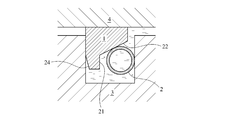
- FIG. 2 is a drawing showing another embodiment of the sealing device of the present invention.
- the cut portion where the coil expander 2 is arranged is composed of a plurality of surfaces, that is, surfaces 21, 22, and 23.
- the surfaces 21 and 22 are inclined with respect to the axial direction of the resin ring 1. 23 is parallel.
- the coil expander 2 contacts the inclined surface 22 and presses the resin ring 1 not only on the inner peripheral surface 13 of the outer member 4 but also on the side wall 11 of the seal ring groove 5 of the inner member 3.
- the inclination angle of the inclined surface 22 with respect to the axial direction is preferably 15 to 45 °, and more preferably 25 to 35 °.
- the cut portion is composed of two surfaces of a surface 21 and a surface 22. It is preferable that the plurality of surfaces include a surface parallel to or perpendicular to the axial direction of the resin ring 1 in order to effectively apply pressure in the outer circumferential direction and the side surface direction of the resin ring 1 by oil pressure.
- the sliding of the resin ring 1 causes the outer peripheral surface 12 to slide in the axial direction with respect to the inner peripheral surface 13 of the outer member 4.
- the outer periphery 12 of the cross section of the resin ring 1 has an arc shape. An embodiment in which the outer periphery 12 has an arc shape is shown in FIG.
- the pressing force in the outer circumferential direction and the side surface direction of the resin ring 1 by the coil expander 2 depends on the expansion force of the coil expander 2 and the angle of the inclined surface 22.
- the pressing force in the side surface direction can be adjusted by slightly inclining the inner peripheral side surface 24.
- the resin ring used in the present invention a so-called engineering plastic obtained by reinforcing PTFE or polyether ether ketone (PEEK) having excellent sliding characteristics, heat resistance, etc. with carbon or carbon fiber is preferably used.
- the fluorine-based resin material exhibits elastic deformation of several percent at room temperature, it can be preferably used for expanding the diameter of an endless type ring having no joint.
- the inner diameter ( ⁇ d) of the resin ring is in the range of 95% or more of the diameter ( ⁇ D) of the inner member, it is possible to increase the diameter of the resin ring without plastic deformation.
- the sealing performance with the side wall of the seal ring groove it is preferably 99.5% or less.
- fluorine-based resin materials examples include polytetrafluoroethylene (PTFE), tetrafluoroethylene / perfluoroalkyl vinyl ether copolymer (PFA), tetrafluoroethylene / ethylene copolymer (ETFE), and polyvinylidene.
- PTFE polytetrafluoroethylene
- PFA tetrafluoroethylene / perfluoroalkyl vinyl ether copolymer
- ETFE tetrafluoroethylene / ethylene copolymer
- PVDF fluoride
- JIS-SWPA77 carbon steel wire, SWOSC-V silicon chrome steel oil tempered wire, SUS304 austenitic stainless steel wire, etc. are preferably used for the coil expander 2 used in the combination seal ring of the present invention. It is preferable to adjust the overall length so that a predetermined tension acts appropriately as a combination seal ring. Further, when the coil expander is disposed in the cut portion of the resin ring, as shown in FIG. 6, the coil expander is accommodated on the outer peripheral side from the inner peripheral surface of the resin ring, that is, the coil expander is inner peripheral surface of the resin ring. It is preferable that it does not protrude from the inner circumference side.
- the seal ring for CVT receives a thermal history depending on the temperature of CVT oil. Considering the use of cold regions and sudden rises in temperature, we experience temperatures from -30 ° C to 120 ° C. When the fluororesin ring receives such a thermal history, if the thickness of the resin ring foot is thin, there is a possibility that the effect of thermal deformation will occur and the seal with the seal ring groove sidewall will be damaged. From this point of view, the opening width (w) on the inner peripheral surface side of the cut portion of the resin ring is preferably 75% or less of the width (h1) of the resin ring. Of course, even if the opening width (w) exceeds 75% of the width (h1) of the resin ring, it can be used satisfactorily if no extreme thermal history is experienced.
- Example 1 Using PTFE resin combined with carbon, an endless type resin ring with no joint was produced.
- the outer diameter (nominal diameter) of the resin ring was 114.5 mm
- the thickness (radial width a1) was 3.2 mm
- the width (axial width h1) was 2.7 mm.
- a cut portion having an opening width (w) on the inner peripheral surface side of 1.0 mm and a radius of curvature of 0.8 mm was formed on the obtained resin ring in a cross section as shown in FIG.
- a coil expander with a winding diameter of 1.5 mm, a free-form pitch of 1.65 mm, and a tension of 10 N when combined with a resin ring was manufactured using SWOSC-V material with a wire diameter of 0.6 mm.
- the leak test was conducted using a leak tester whose outline is shown in FIG.
- the produced combination seal ring is mounted in a seal ring groove 5 provided in the inner member 3 and inserted into the outer member 4.
- the diameter of the inner member 3 of the leak tester is ⁇ 113.4 mm
- the inner diameter of the outer member 4 is ⁇ 114.7 mm
- the groove bottom diameter of the seal ring groove is ⁇ 107.9 mm
- the groove width is 2.8 mm.
- the valve 15 is opened to introduce oil
- the oil pressure in the oil chamber is increased to 1 MPa
- the valve 17 is opened, the air is evacuated and closed again, and then the valve 15 is closed and the inside is sealed.
- Example 17 was opened and the pressure was reduced to atmospheric pressure (0 MPa), and the amount of leakage from the oil outlet 19 was measured. Subsequently, after holding at 120 ° C. for a certain period of time and then giving a heat history to lower to ⁇ 30 ° C., the amount of leakage was measured in the same manner. The heat history was given by opening the valves 15 and 16 and increasing or decreasing the temperature while circulating the oil. The combination seal ring of Example 1 did not leak at all before and after the heat history.
- Example 2 A combined seal ring was produced in the same manner as in Example 1 except that the resin ring 1 had a cut portion composed of three surfaces 21, 22, and 23 as shown in FIG.
- the opening width (w) on the inner peripheral surface side of the cut portion is 2.0 mm (74% of h1)
- the surface 23 is 0.9 mm parallel to the axial direction of the resin ring 1
- the inclination angle of the surface 22 is 30 °.
- the inclination angle of the surface 21 was 80 °.
Abstract
Description
カーボンを複合したPTFE樹脂を用いて、合口のないエンドレスタイプの樹脂リングを作製した。ここで、樹脂リングの外径(呼び径)は114.5 mm、厚さ(径方向幅a1)は3.2mm、幅(軸方向幅h1)は2.7 mmとした。得られた樹脂リングに、図1に示すような断面で、内周面側の開口幅(w)が1.0 mm、曲率半径0.8 mmのカット部を形成した。また、線径0.6 mmのSWOSC-V材を用いて、巻径φ1.5 mm、自由状態のピッチ1.65 mm、樹脂リングと組合せた時の張力10 Nのコイルエキスパンダを製作した。 Example 1
Using PTFE resin combined with carbon, an endless type resin ring with no joint was produced. Here, the outer diameter (nominal diameter) of the resin ring was 114.5 mm, the thickness (radial width a1) was 3.2 mm, and the width (axial width h1) was 2.7 mm. A cut portion having an opening width (w) on the inner peripheral surface side of 1.0 mm and a radius of curvature of 0.8 mm was formed on the obtained resin ring in a cross section as shown in FIG. A coil expander with a winding diameter of 1.5 mm, a free-form pitch of 1.65 mm, and a tension of 10 N when combined with a resin ring was manufactured using SWOSC-V material with a wire diameter of 0.6 mm.
漏れ試験は、図6にその概略を示す漏れ試験機を用いて行った。作製した組合せシールリングは、内側部材3に設けられたシールリング溝5に装着され、外側部材4に挿入される。漏れ試験器の内側部材3の径はφ113.4 mm、外側部材4の内径はφ114.7 mm、シールリング溝の溝底径は φ107.9 mm、溝幅は2.8 mmである。試験は、まず、バルブ15を開けてオイルを導入、オイル室の油圧を1 MPaまで上げ、バルブ17を開けてエアーを抜いて再び閉じた後、バルブ15を閉じて内部を密閉し、その後バルブ17を開けて大気圧(0 MPa)まで圧力を下げて、オイル排出口19からの漏れ量を測定した。続いて、120℃で一定時間保持し、その後-30℃まで下げる熱履歴を与えた後、同様に漏れ量を測定した。熱履歴は、バルブ15と16を開け、オイルを循環しながら昇温又は降温することによって与えた。実施例1の組合せシールリングは、熱履歴前も熱履歴後も漏れは全く生じなかった。 Leak test The leak test was conducted using a leak tester whose outline is shown in FIG. The produced combination seal ring is mounted in a
図2に示すような、3つの面21、22、23からなるカット部を有する樹脂リング1とする以外は、実施例1と同様に組合せシールリングを作製した。ここで、カット部の内周面側の開口幅(w)は2.0 mm(h1の74%)、面23は樹脂リング1の軸方向に平行で0.9 mm、面22の傾斜角度は30°、面21の傾斜角度は80°とした。実施例1と同様な漏れ試験を行った結果、熱履歴前も熱履歴後も漏れは全く生じなかった。 Example 2
A combined seal ring was produced in the same manner as in Example 1 except that the
Claims (9)
- 環状の外側部材の内周面に対向する環状の内側部材の外周面に設けられたシールリング溝に組合せシールリングを装着して、前記外側部材と前記内側部材の間のオイルをシールするシール装置であって、前記組合せシールリングは、外周面が外側部材の内周面と摺接するエンドレスタイプの樹脂リングと、前記樹脂リングを外周方向及び側面方向に押圧するコイルエキスパンダを含み、前記コイルエキスパンダが前記樹脂リングの受圧側面と内周面のコーナーに設けられたカット部に配置され、前記組合せシールリングの内周側が前記シールリング溝の溝底と離間していることを特徴とするシール装置。 A sealing device that seals oil between the outer member and the inner member by attaching a combination seal ring to a seal ring groove provided on the outer peripheral surface of the annular inner member facing the inner peripheral surface of the annular outer member. The combination seal ring includes an endless type resin ring whose outer peripheral surface is in sliding contact with the inner peripheral surface of the outer member, and a coil expander that presses the resin ring in the outer peripheral direction and the side surface direction. A seal characterized in that a panda is disposed at a cut portion provided at a corner of the pressure-receiving side surface and the inner peripheral surface of the resin ring, and an inner peripheral side of the combined seal ring is separated from a groove bottom of the seal ring groove. apparatus.
- 請求項1に記載のシール装置において、前記樹脂リングがフッ素系の樹脂材料からなることを特徴とするシール装置。 The sealing device according to claim 1, wherein the resin ring is made of a fluorine-based resin material.
- 請求項2に記載のシール装置において、前記樹脂リングの内径が前記内側部材の径の95~99.5%の範囲にあることを特徴とするシール装置。 3. The sealing device according to claim 2, wherein an inner diameter of the resin ring is in a range of 95 to 99.5% of a diameter of the inner member.
- 請求項1~3のいずれかに記載のシール装置において、前記カット部が円弧状の凹部からなることを特徴とするシール装置。 The sealing device according to any one of claims 1 to 3, wherein the cut portion is an arcuate concave portion.
- 請求項1~3に記載のシール装置において、前記カット部が複数の面から構成され、少なくとも一つの面は前記樹脂リングの軸方向に対して傾斜した傾斜面であり、前記コイルエキスパンダが前記傾斜面に当接していることを特徴とするシール装置。 The sealing device according to any one of claims 1 to 3, wherein the cut portion includes a plurality of surfaces, at least one surface is an inclined surface inclined with respect to an axial direction of the resin ring, and the coil expander is A sealing device that is in contact with an inclined surface.
- 請求項5に記載のシール装置において、前記複数の面が前記樹脂リングの軸方向に平行及び/又は垂直な面を含むことを特徴とするシール装置。 The sealing device according to claim 5, wherein the plurality of surfaces include surfaces parallel and / or perpendicular to an axial direction of the resin ring.
- 請求項1~6のいずれかに記載のシール装置において、前記コイルエキスパンダが前記樹脂リングの前記内周面より外周側に収容されることを特徴とするシール装置。 The sealing device according to any one of claims 1 to 6, wherein the coil expander is accommodated on the outer peripheral side of the inner peripheral surface of the resin ring.
- 請求項1~6のいずれかに記載のシール装置において、前記コイルエキスパンダが前記樹脂リングの前記内周面から内周側に突出しないことを特徴とするシール装置。 7. The sealing device according to claim 1, wherein the coil expander does not protrude from the inner peripheral surface of the resin ring to the inner peripheral side.
- 請求項1~8のいずれかに記載のシール装置において、前記カット部の内周面側の開口幅が前記樹脂リングの幅h1の75%以下であることを特徴とするシール装置。 9. The sealing device according to claim 1, wherein an opening width on the inner peripheral surface side of the cut portion is 75% or less of a width h1 of the resin ring.
Priority Applications (4)
| Application Number | Priority Date | Filing Date | Title |
|---|---|---|---|
| US14/780,337 US9903474B2 (en) | 2013-03-27 | 2014-03-18 | Seal device |
| CN201480017649.2A CN105102866B (en) | 2013-03-27 | 2014-03-18 | Seal device |
| JP2015508360A JPWO2014156820A1 (en) | 2013-03-27 | 2014-03-18 | Sealing device |
| EP14776446.8A EP2980459B1 (en) | 2013-03-27 | 2014-03-18 | Seal device |
Applications Claiming Priority (2)
| Application Number | Priority Date | Filing Date | Title |
|---|---|---|---|
| JP2013065582 | 2013-03-27 | ||
| JP2013-065582 | 2013-03-27 |
Publications (1)
| Publication Number | Publication Date |
|---|---|
| WO2014156820A1 true WO2014156820A1 (en) | 2014-10-02 |
Family
ID=51623800
Family Applications (1)
| Application Number | Title | Priority Date | Filing Date |
|---|---|---|---|
| PCT/JP2014/057296 WO2014156820A1 (en) | 2013-03-27 | 2014-03-18 | Seal device |
Country Status (5)
| Country | Link |
|---|---|
| US (1) | US9903474B2 (en) |
| EP (1) | EP2980459B1 (en) |
| JP (1) | JPWO2014156820A1 (en) |
| CN (1) | CN105102866B (en) |
| WO (1) | WO2014156820A1 (en) |
Families Citing this family (1)
| Publication number | Priority date | Publication date | Assignee | Title |
|---|---|---|---|---|
| DE102016011448A1 (en) * | 2016-09-22 | 2018-03-22 | Carl Freudenberg Kg | Sealing ring and its use |
Citations (7)
| Publication number | Priority date | Publication date | Assignee | Title |
|---|---|---|---|---|
| JPS53146855U (en) * | 1977-04-25 | 1978-11-18 | ||
| JPS6252258U (en) * | 1985-09-20 | 1987-04-01 | ||
| JP2005264978A (en) * | 2004-03-16 | 2005-09-29 | Toyota Motor Corp | Pressure ring |
| JP2007032446A (en) * | 2005-07-27 | 2007-02-08 | Aisin Seiki Co Ltd | Piston ring holding structure for internal combustion engine |
| JP2008190643A (en) | 2007-02-06 | 2008-08-21 | Ntn Corp | Seal ring |
| JP2008190650A (en) | 2007-02-06 | 2008-08-21 | Ntn Corp | Sealing ring |
| JP2011144847A (en) * | 2010-01-13 | 2011-07-28 | Riken Corp | Seal ring and sealing device |
Family Cites Families (25)
| Publication number | Priority date | Publication date | Assignee | Title |
|---|---|---|---|---|
| US1489464A (en) * | 1923-03-06 | 1924-04-08 | Frank E Small | Piston packing |
| US3057630A (en) * | 1958-08-08 | 1962-10-09 | Sneed John | Seal |
| GB866665A (en) | 1959-02-05 | 1961-04-26 | Ralph Leslie Skinner | An improved shaft seal |
| US3450411A (en) * | 1966-09-28 | 1969-06-17 | Renniks Corp | Seal assembly for valve stems and the like |
| US3717293A (en) * | 1971-06-21 | 1973-02-20 | Shamban & Co W S | Seal assembly |
| US4560174A (en) * | 1983-12-02 | 1985-12-24 | Berco S.P.A. | Multi lip seal |
| FR2590641B1 (en) * | 1985-11-25 | 1989-07-13 | Snecma | COMPOSITE SEALING DEVICE |
| DE3739179C1 (en) * | 1987-11-19 | 1989-05-18 | Busak & Luyken Gmbh & Co | Sealing arrangement |
| DE69112617T2 (en) * | 1991-07-05 | 1996-04-18 | Dixon Resine Spa | Annular seal. |
| US5292138A (en) * | 1992-09-21 | 1994-03-08 | General Elecric Company | Rotor to rotor split ring seal |
| AUPM483194A0 (en) * | 1994-03-31 | 1994-04-28 | Hodgins, Sydney Gilbert | Seals |
| JP3364590B2 (en) * | 1998-02-20 | 2003-01-08 | トヨタ自動車株式会社 | How to install the piston ring |
| JP3324980B2 (en) * | 1998-02-20 | 2002-09-17 | トヨタ自動車株式会社 | Assembling method of piston ring structure |
| BR0202271B1 (en) * | 2001-05-30 | 2011-04-05 | internal combustion engine oil ring. | |
| US6905144B2 (en) * | 2003-07-02 | 2005-06-14 | Delaware Capital Formation | Spring-loaded ‘L’-shaped seal ring |
| CN2641387Y (en) * | 2003-09-19 | 2004-09-15 | 徐州车氏密封有限公司 | L shape sliding ring type combined sealing |
| DE102006023157B3 (en) * | 2006-05-16 | 2008-01-24 | Trelleborg Sealing Solutions Germany Gmbh | Sealing arrangement for pressure relief |
| US20110012312A1 (en) * | 2008-03-10 | 2011-01-20 | Skf Polyseal Inc. | Pressure regulating seal |
| JP2012036962A (en) * | 2010-08-06 | 2012-02-23 | Aisin Aw Co Ltd | Seal structure for continuously-variable transmission |
| CN201731065U (en) * | 2010-08-18 | 2011-02-02 | 徐州科源液压有限公司 | Hydraulic braking combination seal for planetary reducer |
| KR20140017519A (en) * | 2011-01-14 | 2014-02-11 | 가부시끼가이샤 리켄 | Seal ring |
| JP5444420B2 (en) * | 2012-06-26 | 2014-03-19 | 株式会社リケン | Seal member |
| US20150362074A1 (en) * | 2013-02-20 | 2015-12-17 | Nok Corporation | Sealing device |
| US9267441B1 (en) * | 2015-03-17 | 2016-02-23 | Borgwarner Inc. | Multi-piece piston ring for a turbocharger shaft assembly |
| US9752679B2 (en) * | 2015-03-31 | 2017-09-05 | Pratt & Whitney Canada Corp. | Dual pre-load cylindrical seal |
-
2014
- 2014-03-18 CN CN201480017649.2A patent/CN105102866B/en not_active Expired - Fee Related
- 2014-03-18 WO PCT/JP2014/057296 patent/WO2014156820A1/en active Application Filing
- 2014-03-18 US US14/780,337 patent/US9903474B2/en not_active Expired - Fee Related
- 2014-03-18 JP JP2015508360A patent/JPWO2014156820A1/en active Pending
- 2014-03-18 EP EP14776446.8A patent/EP2980459B1/en not_active Not-in-force
Patent Citations (7)
| Publication number | Priority date | Publication date | Assignee | Title |
|---|---|---|---|---|
| JPS53146855U (en) * | 1977-04-25 | 1978-11-18 | ||
| JPS6252258U (en) * | 1985-09-20 | 1987-04-01 | ||
| JP2005264978A (en) * | 2004-03-16 | 2005-09-29 | Toyota Motor Corp | Pressure ring |
| JP2007032446A (en) * | 2005-07-27 | 2007-02-08 | Aisin Seiki Co Ltd | Piston ring holding structure for internal combustion engine |
| JP2008190643A (en) | 2007-02-06 | 2008-08-21 | Ntn Corp | Seal ring |
| JP2008190650A (en) | 2007-02-06 | 2008-08-21 | Ntn Corp | Sealing ring |
| JP2011144847A (en) * | 2010-01-13 | 2011-07-28 | Riken Corp | Seal ring and sealing device |
Also Published As
| Publication number | Publication date |
|---|---|
| CN105102866A (en) | 2015-11-25 |
| CN105102866B (en) | 2017-05-10 |
| EP2980459B1 (en) | 2018-04-25 |
| JPWO2014156820A1 (en) | 2017-02-16 |
| US20160033044A1 (en) | 2016-02-04 |
| EP2980459A1 (en) | 2016-02-03 |
| EP2980459A4 (en) | 2016-11-16 |
| US9903474B2 (en) | 2018-02-27 |
Similar Documents
| Publication | Publication Date | Title |
|---|---|---|
| US9856984B2 (en) | Sealing device | |
| JP5801033B2 (en) | Seal structure | |
| WO2014156820A1 (en) | Seal device | |
| JP6371759B2 (en) | Sealing device | |
| JP6858930B2 (en) | Seal ring and sealing structure | |
| JP5807095B2 (en) | SEAL RING AND SEALING DEVICE | |
| JP5537042B2 (en) | Endless type seal ring and belt type continuously variable transmission | |
| WO2016132981A1 (en) | Tight-sealing device and tight-sealing structure | |
| US11608896B2 (en) | Multiple component seal assembly | |
| JP2005240932A (en) | Sealing device | |
| JP5770109B2 (en) | Lip type seal | |
| JP5459501B2 (en) | Sealing device | |
| JP6574045B2 (en) | Seal ring for hydraulic equipment | |
| JP6677009B2 (en) | Sealed structure | |
| JP5014196B2 (en) | Pulley structure and accessory drive system using the same | |
| JP2011027141A (en) | Seal device | |
| JP2017145878A (en) | Sealing device and sealing structure | |
| JP6623775B2 (en) | Sealed structure | |
| JP2017125570A (en) | Sealing device | |
| JP5444841B2 (en) | Sealing device | |
| WO2017195882A1 (en) | Seal ring | |
| JP2017150590A (en) | Sealing device | |
| JP2017187101A (en) | Sealing structure | |
| JP2010043663A (en) | Sealing device | |
| JP2017187100A (en) | Seal structure |
Legal Events
| Date | Code | Title | Description |
|---|---|---|---|
| WWE | Wipo information: entry into national phase |
Ref document number: 201480017649.2 Country of ref document: CN |
|
| 121 | Ep: the epo has been informed by wipo that ep was designated in this application |
Ref document number: 14776446 Country of ref document: EP Kind code of ref document: A1 |
|
| ENP | Entry into the national phase |
Ref document number: 2015508360 Country of ref document: JP Kind code of ref document: A |
|
| WWE | Wipo information: entry into national phase |
Ref document number: 14780337 Country of ref document: US |
|
| NENP | Non-entry into the national phase |
Ref country code: DE |
|
| WWE | Wipo information: entry into national phase |
Ref document number: 2014776446 Country of ref document: EP |