WO2014156645A1 - ガスタービン用燃料の予熱装置、これを備えているガスタービンプラント、及びガスタービン用燃料の予熱方法 - Google Patents
ガスタービン用燃料の予熱装置、これを備えているガスタービンプラント、及びガスタービン用燃料の予熱方法 Download PDFInfo
- Publication number
- WO2014156645A1 WO2014156645A1 PCT/JP2014/056477 JP2014056477W WO2014156645A1 WO 2014156645 A1 WO2014156645 A1 WO 2014156645A1 JP 2014056477 W JP2014056477 W JP 2014056477W WO 2014156645 A1 WO2014156645 A1 WO 2014156645A1
- Authority
- WO
- WIPO (PCT)
- Prior art keywords
- steam
- fuel
- line
- gas turbine
- preheater
- Prior art date
- Legal status (The legal status is an assumption and is not a legal conclusion. Google has not performed a legal analysis and makes no representation as to the accuracy of the status listed.)
- Ceased
Links
Images



Classifications
-
- F—MECHANICAL ENGINEERING; LIGHTING; HEATING; WEAPONS; BLASTING
- F02—COMBUSTION ENGINES; HOT-GAS OR COMBUSTION-PRODUCT ENGINE PLANTS
- F02C—GAS-TURBINE PLANTS; AIR INTAKES FOR JET-PROPULSION PLANTS; CONTROLLING FUEL SUPPLY IN AIR-BREATHING JET-PROPULSION PLANTS
- F02C7/00—Features, components parts, details or accessories, not provided for in, or of interest apart form groups F02C1/00 - F02C6/00; Air intakes for jet-propulsion plants
- F02C7/22—Fuel supply systems
- F02C7/224—Heating fuel before feeding to the burner
-
- F—MECHANICAL ENGINEERING; LIGHTING; HEATING; WEAPONS; BLASTING
- F01—MACHINES OR ENGINES IN GENERAL; ENGINE PLANTS IN GENERAL; STEAM ENGINES
- F01K—STEAM ENGINE PLANTS; STEAM ACCUMULATORS; ENGINE PLANTS NOT OTHERWISE PROVIDED FOR; ENGINES USING SPECIAL WORKING FLUIDS OR CYCLES
- F01K23/00—Plants characterised by more than one engine delivering power external to the plant, the engines being driven by different fluids
- F01K23/02—Plants characterised by more than one engine delivering power external to the plant, the engines being driven by different fluids the engine cycles being thermally coupled
- F01K23/06—Plants characterised by more than one engine delivering power external to the plant, the engines being driven by different fluids the engine cycles being thermally coupled combustion heat from one cycle heating the fluid in another cycle
- F01K23/10—Plants characterised by more than one engine delivering power external to the plant, the engines being driven by different fluids the engine cycles being thermally coupled combustion heat from one cycle heating the fluid in another cycle with exhaust fluid of one cycle heating the fluid in another cycle
-
- F—MECHANICAL ENGINEERING; LIGHTING; HEATING; WEAPONS; BLASTING
- F01—MACHINES OR ENGINES IN GENERAL; ENGINE PLANTS IN GENERAL; STEAM ENGINES
- F01K—STEAM ENGINE PLANTS; STEAM ACCUMULATORS; ENGINE PLANTS NOT OTHERWISE PROVIDED FOR; ENGINES USING SPECIAL WORKING FLUIDS OR CYCLES
- F01K7/00—Steam engine plants characterised by the use of specific types of engine; Plants or engines characterised by their use of special steam systems, cycles or processes; Control means specially adapted for such systems, cycles or processes; Use of withdrawn or exhaust steam for feed-water heating
- F01K7/16—Steam engine plants characterised by the use of specific types of engine; Plants or engines characterised by their use of special steam systems, cycles or processes; Control means specially adapted for such systems, cycles or processes; Use of withdrawn or exhaust steam for feed-water heating the engines being only of turbine type
- F01K7/22—Steam engine plants characterised by the use of specific types of engine; Plants or engines characterised by their use of special steam systems, cycles or processes; Control means specially adapted for such systems, cycles or processes; Use of withdrawn or exhaust steam for feed-water heating the engines being only of turbine type the turbines having inter-stage steam heating
-
- F—MECHANICAL ENGINEERING; LIGHTING; HEATING; WEAPONS; BLASTING
- F02—COMBUSTION ENGINES; HOT-GAS OR COMBUSTION-PRODUCT ENGINE PLANTS
- F02C—GAS-TURBINE PLANTS; AIR INTAKES FOR JET-PROPULSION PLANTS; CONTROLLING FUEL SUPPLY IN AIR-BREATHING JET-PROPULSION PLANTS
- F02C3/00—Gas-turbine plants characterised by the use of combustion products as the working fluid
- F02C3/04—Gas-turbine plants characterised by the use of combustion products as the working fluid having a turbine driving a compressor
-
- F—MECHANICAL ENGINEERING; LIGHTING; HEATING; WEAPONS; BLASTING
- F02—COMBUSTION ENGINES; HOT-GAS OR COMBUSTION-PRODUCT ENGINE PLANTS
- F02C—GAS-TURBINE PLANTS; AIR INTAKES FOR JET-PROPULSION PLANTS; CONTROLLING FUEL SUPPLY IN AIR-BREATHING JET-PROPULSION PLANTS
- F02C7/00—Features, components parts, details or accessories, not provided for in, or of interest apart form groups F02C1/00 - F02C6/00; Air intakes for jet-propulsion plants
- F02C7/12—Cooling of plants
- F02C7/14—Cooling of plants of fluids in the plant, e.g. lubricant or fuel
-
- F—MECHANICAL ENGINEERING; LIGHTING; HEATING; WEAPONS; BLASTING
- F05—INDEXING SCHEMES RELATING TO ENGINES OR PUMPS IN VARIOUS SUBCLASSES OF CLASSES F01-F04
- F05D—INDEXING SCHEME FOR ASPECTS RELATING TO NON-POSITIVE-DISPLACEMENT MACHINES OR ENGINES, GAS-TURBINES OR JET-PROPULSION PLANTS
- F05D2220/00—Application
- F05D2220/30—Application in turbines
- F05D2220/32—Application in turbines in gas turbines
-
- F—MECHANICAL ENGINEERING; LIGHTING; HEATING; WEAPONS; BLASTING
- F05—INDEXING SCHEMES RELATING TO ENGINES OR PUMPS IN VARIOUS SUBCLASSES OF CLASSES F01-F04
- F05D—INDEXING SCHEME FOR ASPECTS RELATING TO NON-POSITIVE-DISPLACEMENT MACHINES OR ENGINES, GAS-TURBINES OR JET-PROPULSION PLANTS
- F05D2240/00—Components
- F05D2240/35—Combustors or associated equipment
-
- F—MECHANICAL ENGINEERING; LIGHTING; HEATING; WEAPONS; BLASTING
- F05—INDEXING SCHEMES RELATING TO ENGINES OR PUMPS IN VARIOUS SUBCLASSES OF CLASSES F01-F04
- F05D—INDEXING SCHEME FOR ASPECTS RELATING TO NON-POSITIVE-DISPLACEMENT MACHINES OR ENGINES, GAS-TURBINES OR JET-PROPULSION PLANTS
- F05D2260/00—Function
- F05D2260/20—Heat transfer, e.g. cooling
- F05D2260/232—Heat transfer, e.g. cooling characterized by the cooling medium
- F05D2260/2322—Heat transfer, e.g. cooling characterized by the cooling medium steam
-
- Y—GENERAL TAGGING OF NEW TECHNOLOGICAL DEVELOPMENTS; GENERAL TAGGING OF CROSS-SECTIONAL TECHNOLOGIES SPANNING OVER SEVERAL SECTIONS OF THE IPC; TECHNICAL SUBJECTS COVERED BY FORMER USPC CROSS-REFERENCE ART COLLECTIONS [XRACs] AND DIGESTS
- Y02—TECHNOLOGIES OR APPLICATIONS FOR MITIGATION OR ADAPTATION AGAINST CLIMATE CHANGE
- Y02E—REDUCTION OF GREENHOUSE GAS [GHG] EMISSIONS, RELATED TO ENERGY GENERATION, TRANSMISSION OR DISTRIBUTION
- Y02E20/00—Combustion technologies with mitigation potential
- Y02E20/16—Combined cycle power plant [CCPP], or combined cycle gas turbine [CCGT]
Definitions
- the present invention relates to a gas turbine plant preheating device for a gas turbine in a gas turbine including a plurality of combustors for combusting fuel to generate combustion gas, and a turbine driven by the combustion gas, and a gas turbine plant including the same. , And a gas turbine fuel preheating method.
- the gas turbine includes a compressor that compresses air, a plurality of combustors that generate combustion gas by burning fuel in the air compressed by the compressor, and a turbine that is driven by the combustion gas. .
- the fuel supplied to the combustor is often preheated before being supplied to the combustor in order to increase the combustion efficiency in the combustor.
- Patent Document 1 discloses a gas turbine plant that preheats fuel supplied to a combustor.
- This gas turbine plant supplies a gas turbine, an exhaust heat recovery boiler that generates steam by the heat of exhaust gas from the gas turbine, a steam turbine that is driven by the steam generated by the exhaust heat recovery boiler, and a combustor.
- a preheater for heating the fuel to be produced.
- a first steam line is connected to the preheater for supplying steam generated in the exhaust heat recovery boiler as a fuel heating source in the preheater.
- the preheater is connected to a second steam line that guides the steam that has heated the fuel to the tail cylinder of the combustor.
- a third steam line is connected to the combustor of the combustor to guide the steam that has cooled the transition to the steam turbine.
- the gas turbine plant further includes a temperature reducing spray line that injects water into the second steam line in order to cool the steam flowing through the second steam line, that is, the steam that heated the fuel. .
- An object of the present invention is to provide a gas turbine fuel preheating device capable of enhancing the thermal efficiency of the entire gas turbine plant, a gas turbine plant equipped with the same, and a gas turbine fuel preheating method. To do.
- An apparatus for preheating a gas turbine fuel as one aspect according to the invention for solving the above-described problems Steam is used to cool the high-temperature components to any one of a combustor that burns fuel and generates combustion gas and a turbine that is driven by the combustion gas and that is in contact with the combustion gas.
- the cooling steam line to be supplied, the superheated steam line through which the superheated steam that has passed through the high-temperature component passes, the superheated steam supplied from the superheated steam line, and the fuel supplied to the combustor are heated.
- a preheater for preheating the fuel.
- the fuel is heated by the superheated steam heated by the cooling of the combustor, so that the heat of the combustor can be used effectively. Therefore, according to the preheating device, the thermal efficiency of the entire gas turbine plant can be increased.
- the preheater may condense the superheated steam by heat exchange with the fuel.
- the superheated steam when the fuel is heated, the superheated steam is condensed, so that the heat of the superheated steam can be fully utilized. Further, in the preheating device, since the superheated steam is condensed by heat exchange with the fuel, the heat exchange rate between the superheated steam and the fuel is increased, and the preheater can be downsized.
- the superheated steam line may supply the superheated steam to each of the plurality of preheaters.
- the steam that passes through the steam that does not pass through the high-temperature components, the steam that is supplied from the steam circuit that is supplied from the preceding steam, and the combustor that is supplied to the combustor A pre-stage preheater that preheats the fuel by exchanging heat with the fuel, and the pre-stage preheater and the post-stage so that the fuel preheated by the pre-stage preheater is supplied to the post-stage preheater that is the preheater. And a fuel line connecting the preheater.
- the fuel is heated in two stages, so that a higher temperature fuel can be supplied to the combustor, and the combustion efficiency of the fuel in the combustor can be increased.
- the branch steam line branched from the superheated steam line and leading a part of the superheated steam flowing through the superheated steam line to the outside of the preheater,
- a cooling steam control valve for adjusting the flow rate of the steam supplied to the high-temperature component via the cooling steam line, and a superheated steam control valve for adjusting the flow rate of the superheated steam supplied to the preheater via the superheated steam line And may be provided.
- the flow rate of the steam supplied to the high temperature parts via the cooling steam line and the preheater via the superheated steam line can be adjusted respectively.
- a gas turbine plant as one aspect according to the invention for solving the above problems is as follows: Any of the above gas turbine fuel preheating apparatus, a gas turbine having the combustor and the turbine, a steam generating source for generating steam, and a condensate for returning the steam generated in the steam generating source to water.
- a cooling line that supplies the steam generated by the steam generation source to the high-temperature component.
- the thermal efficiency of the entire gas turbine plant can be increased.
- the steam generation source may include an exhaust heat recovery boiler that generates steam by heat of exhaust gas from the turbine.
- the gas turbine plant as another aspect according to the invention for solving the above-described problems is A gas turbine fuel preheating device comprising the branch steam line, a gas turbine having the combustor and the turbine, an exhaust heat recovery boiler for generating steam by heat of exhaust gas from the turbine, and A steam turbine driven by the steam generated in the exhaust heat recovery boiler, a condenser for returning the steam that has driven the steam turbine to water, and water generated by the condenser is supplied to the exhaust heat recovery boiler A water supply line, and a water recovery line that sends the water condensed by the superheated steam by heat exchange with the fuel in the preheater to the condenser or the water supply line,
- the exhaust heat recovery boiler includes a steam generating unit that generates steam by the heat of the exhaust gas, a reheating unit that superheats the steam generated by the steam generating unit, and sends the superheated steam to the steam turbine; And the cooling steam line supplies steam generated in the steam generation unit before being superheated in the reheating unit to the
- surplus superheated steam that is not used for preheating the fuel is supplied to the steam turbine through the branch steam line, so that surplus superheated steam can also be used effectively.
- the steam generation source may include an auxiliary boiler that generates steam with a heat source different from the exhaust gas from the turbine.
- the gas turbine plant cools high-temperature components even if it does not have an exhaust heat recovery device, even if it has an exhaust heat recovery device, or if the exhaust heat recovery device is not in steady operation at the start-up stage of the gas turbine.
- the fuel can be preheated.
- a gas turbine fuel preheating device comprising the branch steam line, a gas turbine having the combustor and the turbine, an auxiliary boiler for generating steam from a heat source different from the exhaust gas from the turbine, and The condenser that returns the steam generated in the auxiliary boiler to water, a water supply line that supplies the water generated in the condenser to the auxiliary boiler, and the superheated steam by heat exchange with the fuel in the preheater
- a water recovery line for sending condensed water to the condenser or the water supply line
- the cooling steam line supplies steam generated in the auxiliary boiler to the high-temperature component
- the branch steam line guides the superheated steam to the condenser.
- a method for preheating a gas turbine fuel as one aspect according to the invention for solving the above-described problems Steam is used to cool the high-temperature components to any one of a combustor that generates combustion gas by burning fuel and a turbine that is driven by the combustion gas and that is in contact with the combustion gas.
- the preheating method since the fuel is heated with superheated steam that has been heated by cooling the combustor, the heat of the combustor can be used effectively. Therefore, according to the preheating method, the thermal efficiency of the entire gas turbine plant can be increased.
- the superheated steam in the fuel preheating step, may be condensed by heat exchange with the fuel.
- the heat of the superheated steam can be fully utilized. Furthermore, in the preheating method, since the superheated steam is condensed by heat exchange with the fuel, the heat exchange rate between the superheated steam and the fuel can be increased.
- the fuel is heated by superheated steam that has been superheated by cooling the combustor, so that the heat of the combustor can be used effectively.
- the thermal efficiency of the entire gas turbine plant can be increased.
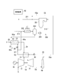
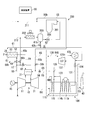
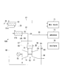
- 1 is a system diagram of a gas turbine plant in a first embodiment according to the present invention. It is a typical sectional view of a gas turbine in a first embodiment concerning the present invention. It is a systematic diagram of the gas turbine plant in 2nd embodiment which concerns on this invention. It is a systematic diagram of the gas turbine plant in 3rd embodiment which concerns on this invention. It is a systematic diagram of the fuel preheating apparatus in the 1st modification which concerns on this invention. It is a systematic diagram of the fuel preheating apparatus in the 2nd modification which concerns on this invention.
- the gas turbine plant of the present embodiment generates steam by the heat of the gas turbine 10, the generator 15 that generates power by driving the gas turbine 10, and the exhaust gas EG exhausted from the gas turbine 10.
- the exhaust heat recovery device 100 to be discharged the chimney 40 that discharges the exhaust gas EG that has passed through the exhaust heat recovery device 100 to the atmosphere, the fuel preheating device 50 that preheats the fuel to be supplied to the gas turbine 10, the gas turbine 10 and the fuel preheating And a control device 90 for controlling the device 50 and the like.
- the gas turbine 10 is driven by a compressor 11 that compresses air, a plurality of combustors 21 that combust fuel F in the air compressed by the compressor 11 to generate combustion gas, and high-temperature and high-pressure combustion gas.
- a turbine 31 The turbine rotor of the turbine 31 and the compressor rotor of the compressor 11 rotate about the same axis, and are connected to each other to form a gas turbine rotor.
- the rotor of the generator 15 is connected to this gas turbine rotor.
- the combustor 21 combusts the fuel F in the air A from the compressor 11 and generates combustion gas, and compresses the combustion cylinder 23 in the combustion cylinder 23.
- an injector 22 for injecting air A and fuel F from the machine 11.
- a fuel line 29 that supplies fuel F from an external fuel supply source to the injector 22 is connected to the injector 22.
- a steam flow path 24 through which steam passes is formed in the member forming the combustion cylinder 23 in order to cool the member.
- the turbine 31 includes a turbine rotor (hereinafter simply referred to as a rotor) 32 that rotates about the axis Ar by combustion gas from the combustor 21 and a casing 35 that rotatably covers the rotor 32.
- the rotor 32 includes a rotor main body 33 extending in the axial direction parallel to the axis Ar, and a plurality of moving blades 34 fixed to the outer periphery of the rotor main body 33.
- a plurality of stationary blades 36 are fixed to the inner peripheral surface of the casing 35.
- a combustion gas flow path 37 through which the combustion gas from the combustor 21 passes is formed between the inner peripheral surface of the casing 35 and the outer peripheral surface of the rotor body 33.
- the plurality of combustors 21 are fixed to the casing 35 of the turbine 31 side by side in the circumferential direction about the axis Ar.
- the exhaust heat recovery apparatus 100 includes an exhaust heat recovery boiler 110 that generates steam by the heat of combustion gas that drives the turbine 31, that is, exhaust gas EG exhausted from the gas turbine 10, and exhaust heat.
- Steam turbines 121a, 121b, and 121c driven by steam generated in the recovery boiler 110, a generator 122 that generates power by driving the steam turbines 121a, 121b, and 121c, and condensate for returning the steam that has driven the steam turbine 121a to water.
- a water supply pump 124 for returning the water in the condenser 123 to the exhaust heat recovery boiler 110.
- the exhaust heat recovery apparatus 100 includes a low-pressure steam turbine 121a, an intermediate-pressure steam turbine 121b, and a high-pressure steam turbine 121c as the steam turbines 121a, 121b, and 121c.
- the exhaust heat recovery boiler 110 includes a low-pressure steam generator 111a that generates low-pressure steam LS, an intermediate-pressure steam generator 111b that generates intermediate-pressure steam IS, a high-pressure steam generator 111c that generates high-pressure steam HS, And a reheater 115 that heats the steam that has driven the high-pressure steam turbine 121c.
- the low-pressure steam generator 111a, the intermediate-pressure steam generator 111b, and the high-pressure steam generator 111c are all heated by the economizers 112a, 112b, and 112c that heat water and the economizers 112a, 112b, and 112c. It has evaporators 113a, 113b, 113c that convert water into steam, and superheaters 114a, 114b, 114c that superheat the steam generated in the evaporators 113a, 113b, 113c.
- the medium pressure steam generator 111b and the high pressure steam generator 111c are water heated by the economizer 112a of the low pressure steam generator 111a, in addition to the economizers 112b and 112c, the evaporators 113b and 113c, and the superheaters 114b and 114c.
- the economizer 112c of the high-pressure steam generator 111c is the high-pressure economizer 112c
- the evaporator 113c of the high-pressure steam generator 111c is the high-pressure evaporator 113c
- the superheater 114c of the high-pressure steam generator 111c is the high-pressure superheater. 114c.
- the economizer 112b of the intermediate pressure steam generator 111b is an intermediate pressure economizer 112b
- the evaporator 113b of the intermediate pressure steam generator 111b is an intermediate pressure evaporator 113b
- the superheater 114b of the intermediate pressure steam generator 111b is intermediate.
- the pressure superheater 114b is used.
- the economizer 112a of the low-pressure steam generator 111a is the low-pressure economizer 112a
- the evaporator 113a of the low-pressure steam generator 111a is the low-pressure evaporator 113a
- the superheater 114a of the low-pressure steam generator 111a is the low-pressure superheater 114a.
- the pump 116b of the intermediate pressure steam generator 111b is an intermediate pressure pump 116b
- the pump 116c of the high pressure steam generator 111c is a high pressure pump 116c.
- Reheater 115 high pressure superheater 114c, high pressure evaporator 113c, high pressure economizer 112c, medium pressure superheater 114b, medium pressure evaporator 113b, medium pressure economizer 112b, low pressure superheater 114a, low pressure evaporator 113a,
- the low-pressure economizer 112a is arranged in this order toward the downstream side of the exhaust gas EG from the turbine 31 toward the chimney 40.
- the condenser 123 and the low-pressure economizer 112a are connected by a water supply line 131.
- the water supply line 131 is provided with the above-described water supply pump 124.
- the low pressure superheater 114a and the steam inlet of the low pressure steam turbine 121a are connected by a low pressure steam line 132 that sends the low pressure steam LS from the low pressure superheater 114a to the low pressure steam turbine 121a.
- the steam outlet of the low-pressure steam turbine 121 a and the condenser 123 are connected to each other so that the low-pressure steam LS that drives the low-pressure steam turbine 121 a is supplied to the condenser 123.
- the high pressure superheater 114c and the steam inlet of the high pressure steam turbine 121c are connected by a high pressure steam line 138 that sends the high pressure steam HS from the high pressure superheater 114c to the high pressure steam turbine 121c.
- the steam outlet of the high pressure steam turbine 121c and the steam inlet of the reheater 115 are connected by a high pressure steam recovery line 139 that sends the high pressure steam HS from the high pressure steam turbine 121c to the reheater 115.
- the steam outlet of the reheater 115 and the steam inlet of the intermediate pressure steam turbine 121b are connected by a reheat steam line 136 that sends the high pressure steam HS superheated by the reheater 115 to the intermediate pressure steam turbine 121b as the reheat steam RHS.
- An intermediate pressure steam recovery line 137 is connected to the steam outlet of the intermediate pressure steam turbine 121b.
- the intermediate pressure steam recovery line 137 merges with the low pressure steam line 132.
- An intermediate pressure steam line 133 is connected to the steam outlet of the intermediate pressure superheater 114b.
- the intermediate pressure steam line 133 joins the high pressure steam recovery line 139.
- the condenser 123 is, for example, a water-cooled condenser that exchanges heat between seawater and steam to condense the steam.
- the fuel preheating device 50 includes a preheater 51 that heats the fuel F supplied to the combustor 21, a cooling steam line 55 that supplies steam generated in the exhaust heat recovery boiler 110 to the combustor 21 as cooling steam CS, and a combustor.
- the superheated steam line 57 that supplies the superheated steam SS that has been heated by passing through the preheater 51 to the preheater 51, and the water recovery line that sends the water in which the superheated steam SS is condensed in the preheater 51 to the water supply line 131 of the exhaust heat recovery apparatus 100.
- the preheater 51 is provided in a fuel line 29 that supplies fuel F to the combustor 21.
- the preheater 51 is a multi-tube heat exchanger and includes a casing 52 and a plurality of tubes 53 provided in the casing 52.
- the fuel F that has passed through the fuel line 29 passes through the pipe 53.
- the cooling steam line 55 branches off from the high-pressure steam recovery line 139 that sends the high-pressure steam HS from the high-pressure steam turbine 121c to the reheater 115.
- the cooling steam line 55 is provided with a cooling steam control valve 56 that adjusts the flow rate of steam supplied from the cooling steam line 55 to the combustor 21.
- the cooling steam line 55 is connected to one end portion of the steam flow path 24 formed in the combustion cylinder 23 of the combustor 21.
- One end of the superheated steam line 57 is connected to the other end of the steam flow path 24.
- the other end of the superheated steam line 57 is connected to the casing 52 of the preheater 51 as shown in FIG.
- the superheated steam SS that has passed through the superheated steam line 57 flows into the casing 52 of the preheater 51 and out of the pipe 53 of the preheater 51.
- the superheated steam line 57 is provided with a superheated steam control valve 58 that adjusts the flow rate of the superheated steam SS that flows into the preheater 51 via the superheated steam line 57.
- One end of the water recovery line 61 is connected to the casing 52 of the preheater 51.
- the other end of the water recovery line 61 is connected to a position on the upstream side (condenser side) of the water supply line 131 of the exhaust heat recovery apparatus 100 from the position where the water supply pump 124 is provided.
- the branch steam line 65 branches from the superheated steam line 57 at a position upstream (combustor 21 side) of the superheated steam line 57 from the position where the superheated steam control valve 58 is provided.
- the branch steam line 65 is connected to the reheat steam line 136 of the exhaust heat recovery apparatus 100.
- the other end of the water recovery line 61 is connected to the water supply line 131 of the exhaust heat recovery apparatus 100, but the other end of the water recovery line 61 is connected to the condenser 123 of the exhaust heat recovery apparatus 100. May be.
- the superheated steam control valve 58 for adjusting the flow rate of the superheated steam SS is provided in the superheated steam line 57, it may be provided in the branch steam line 65.
- the compressor 11 of the gas turbine 10 compresses the air A in the atmosphere and supplies the compressed air A to the combustor 21 as shown in FIG. Further, the fuel F from the fuel line 29 is also supplied to the combustor 21. In the combustion cylinder 23 of the combustor 21, the fuel F is combusted in the compressed air A, and high-temperature and high-pressure combustion gas is generated. The combustion gas is sent from the combustion cylinder 23 into the combustion gas flow path 37 of the turbine 31, and the rotor 32 of the turbine 31 is rotated. The generator 15 connected to the gas turbine 10 generates power by the rotation of the rotor 32.
- the combustion gas obtained by rotating the rotor 32 of the turbine 31 is exhausted from the gas turbine 10 as exhaust gas EG, and is discharged from the chimney 40 to the atmosphere via the exhaust heat recovery boiler 110.
- the exhaust heat recovery apparatus 100 recovers heat contained in the exhaust gas EG in the process in which the exhaust gas EG from the gas turbine 10 passes through the exhaust heat recovery boiler 110.
- water from the condenser 123 is supplied to the low-pressure economizer 112 a on the most downstream side (chimney 40 side) via the water supply line 131.
- the low pressure economizer 112a heats this water by exchanging heat with the exhaust gas EG.
- a part of the water heated by the low pressure economizer 112a is further heated by the low pressure evaporator 113a to become steam.
- This steam is further heated by the low-pressure superheater 114a and supplied as low-pressure steam LS to the low-pressure steam turbine 121a via the low-pressure steam line 132.
- the steam that has driven the low-pressure steam turbine 121 a returns to water in the condenser 123.
- This water is supplied again from the condenser 123 to the low-pressure economizer 112 a through the water supply line 131.
- the other part of the water heated by the low pressure economizer 112a is pressurized by the medium pressure pump 116b and sent to the medium pressure economizer 112b, and the remaining water heated by the low pressure economizer 112a is It is pressurized by the high pressure pump 116c and sent to the high pressure economizer 112c.
- the high pressure economizer 112c heats the water sent from the high pressure pump 116c by exchanging heat with the exhaust gas EG.
- the water heated by the high pressure economizer 112c is further heated by the high pressure evaporator 113c to become steam.
- This steam is further heated by the high-pressure superheater 114c and supplied as high-pressure steam HS to the high-pressure steam turbine 121c via the high-pressure steam line 138.
- the medium pressure economizer 112b heats the water sent from the medium pressure pump 116b by exchanging heat with the exhaust gas EG.
- the water heated by the medium pressure economizer 112b is further heated by the intermediate pressure evaporator 113b to become steam.
- This steam is further superheated by the intermediate pressure superheater 114b, and a part of the steam is converted to an intermediate pressure steam IS, via the intermediate pressure steam line 133 and the high pressure steam recovery line 139, in the most upstream side of the exhaust heat recovery boiler 110 ( It is sent to the reheater 115 on the gas turbine 10 side.
- the high-pressure steam HS driving the high-pressure steam turbine 121c and the medium-pressure steam IS from the intermediate-pressure superheater 114b are most upstream (gas turbine 10 side) in the exhaust heat recovery boiler 110 via the high-pressure steam recovery line 139.
- the reheater 115 superheats this steam by exchanging heat with the exhaust gas EG, and supplies it as reheated steam RHS to the intermediate pressure steam turbine 121b via the reheated steam line 136.
- the reheated steam RHS that has driven the intermediate pressure steam turbine 121b is supplied to the low pressure steam turbine 121a via the intermediate pressure steam recovery line 137 and the low pressure steam line 132.
- a part of the high-pressure steam HS that has driven the high-pressure steam turbine 121c is sent to the combustor 21 as the cooling steam CS through the high-pressure steam recovery line 139 and the cooling steam line 55 as described above.
- the flow rate of the cooling steam CS supplied to the combustor 21 is adjusted by the cooling steam control valve 56 provided in the cooling steam line 55.
- the cooling steam CS from the cooling steam line 55 flows into the steam flow path 24 formed in the combustion cylinder 23 of the combustor 21.
- the cooling steam CS exchanges heat with the combustion cylinder 23 heated by the flame and the combustion gas, and cools the combustion cylinder 23 (cooling steam supply process).
- the cooling steam CS is overheated to become superheated steam SS.
- the superheated steam SS flows into the casing 52 of the preheater 51 through the superheated steam line 57. At this time, the flow rate of the superheated steam SS flowing into the casing 52 of the preheater 51 is adjusted by the superheated steam control valve 58 provided in the superheated steam line 57.
- the superheated steam SS that does not flow into the casing 52 of the preheater 51 that is, the surplus superheated steam SS that is not used for preheating the fuel F is divided into the branch steam line 65 and the reheat steam line. It is supplied to the intermediate pressure steam turbine 121b via 136.
- the superheated steam SS that has flowed into the casing 52 of the preheater 51 exchanges heat with the fuel F flowing through the pipe 53 of the preheater 51 to heat the fuel F (fuel preheating step).
- the fuel F is supplied to the injector 22 of the combustor 21 through the fuel line 29 as described above.
- the superheated steam SS is cooled and condensed by heat exchange with the fuel F to become water. This water returns to the condenser 123 or the water supply line 131 of the exhaust heat recovery apparatus 100 via the water recovery line 61.
- the fuel F is heated by the superheated steam SS that has been superheated by cooling the combustor 21, so that the heat of the combustor 21 can be used effectively.
- the superheated steam SS is condensed, so that the heat of the superheated steam SS can be fully utilized.
- surplus superheated steam SS that is not used for preheating the fuel F is supplied to the intermediate pressure steam turbine 121b, so that surplus superheated steam SS can also be used. Therefore, in this embodiment, the thermal efficiency in the whole gas turbine plant can be improved.
- the heat exchange rate between the superheated steam SS and the fuel is increased, and the preheater 51 can be downsized.
- a gas turbine plant includes a heat source different from the exhaust gas EG from the gas turbine 10, for example, an auxiliary boiler that generates steam by heat generated by burning fuel separately.
- a part of the steam generated in the auxiliary boiler is led to the combustor 21 as the cooling steam CS through the cooling steam line 55, so that the exhaust heat recovery boiler 110 does not generate steam, for example, Even in the startup stage of the gas turbine 10, the combustor 21 can be cooled and the fuel F can be preheated.
- the superheated steam SS exchanges heat with the fuel to condense into water. This water is sent to the condenser 123 or the water supply line 131 via the water recovery line 61. Therefore, in this embodiment, even when the exhaust heat recovery boiler 110 is not in a steady operation and the steam from the auxiliary boiler is used, this steam is condensed by heat exchange with the fuel F. Can be used very effectively.
- the gas turbine plant of the present embodiment generates steam, a gas turbine 10, a generator 15 that generates electric power by driving the gas turbine 10, a chimney 40 that discharges exhaust gas EG exhausted from the gas turbine 10 to the atmosphere, and steam.
- the auxiliary steam generator 200, a fuel preheating device 50a for preheating the fuel F supplied to the combustor 21, and a control device 90 for controlling the gas turbine 10, the fuel preheating device 50a, and the like are provided.
- the gas turbine plant of this embodiment includes an auxiliary steam generator 200 instead of the exhaust heat recovery device 100 in the gas turbine plant of the first embodiment.
- the auxiliary steam generator 200 includes an auxiliary boiler 201, a condenser 202 that returns the steam generated by the auxiliary boiler 201 to water, a deaeration tank 203 that removes dissolved gas in water from the condenser 202, and a degassing tank 203.
- a water supply pump 204 that supplies water from the air tank 203 to the auxiliary boiler 201.
- the auxiliary boiler 201 is a heat source different from the exhaust gas from the gas turbine 10, for example, a boiler that generates steam by heat generated by separately burning fuel.
- the auxiliary boiler 201 is connected to an auxiliary steam line 211 that supplies the steam generated here to various facilities.
- a steam recovery line 212 that sends steam used in various facilities to the condenser 202.
- the condenser 202 is, for example, an air-cooled condenser that cools steam with air.
- the condenser 202 and the auxiliary boiler 201 are connected by a water supply line 213.
- the water supply line 213 is provided with the above-described deaeration tank 203 and a water supply pump 204 further downstream thereof.
- the fuel preheating device 50a of the present embodiment uses the preheater 51 that heats the fuel supplied to the combustor 21 and the steam generated in the auxiliary boiler 201 as the cooling steam CS.
- a water recovery line 61 a to be sent to the deaeration tank 203 of the auxiliary steam generator 200 and a branch steam line 65 a branched from the superheated steam line 57 are provided.
- the preheater 51 is provided in the fuel line 29 that supplies the fuel F to the combustor 21 in the same manner as the preheater 51 in the first embodiment.
- the cooling steam line 55a branches off from the auxiliary steam line 211 of the auxiliary steam generating apparatus 200.
- the cooling steam line 55a is provided with a cooling steam control valve 56 for adjusting the flow rate of steam supplied from the cooling steam line 55a to the combustor 21.
- the cooling steam line 55a is connected to one end portion of the steam flow path 24 formed in the combustion cylinder 23 of the combustor 21 as in the first embodiment.
- One end of the superheated steam line 57 is connected to the end of the steam flow path 24 formed in the combustion cylinder 23.
- the other end of the superheated steam line 57 is connected to the casing 52 of the preheater 51.
- the superheated steam line 57 is provided with a superheated steam control valve 58 that adjusts the flow rate of the superheated steam SS flowing into the preheater 51.
- One end of the water recovery line 61 a is connected to the casing 52 of the preheater 51.
- the other end of the water recovery line 61a is connected to the deaeration tank 203 of the auxiliary steam generator 200.
- the branch steam line 65a branches from the superheated steam line 57 at a position upstream (combustor 21 side) of the superheated steam line 57 from the position where the superheated steam control valve 58 is provided.
- the branch steam line 65a is connected to the steam recovery line 212 of the auxiliary steam generator 200.
- the cooling steam control valve 56 provided in the cooling steam line 55a and the superheated steam control valve 58 provided in the superheated steam line 57 are both in response to an instruction from the control device 90, as in the first embodiment. Opens and closes.
- the other end of the water recovery line 61a is connected to the deaeration tank 203 of the auxiliary steam generator 200, but it may be connected to the condenser 202 of the auxiliary steam generator 200.
- the gas turbine 10 operates in the same manner as in the first embodiment.
- a part of the steam generated in the auxiliary boiler 201 of the auxiliary steam generator 200 is sent to the combustor 21 as the cooling steam CS via the auxiliary steam line 211 and the cooling steam line 55a.
- the flow rate of the cooling steam CS supplied to the combustor 21 is adjusted by the cooling steam control valve 56 provided in the cooling steam line 55a.
- the cooling steam CS from the cooling steam line 55a flows into the steam flow path 24 formed in the combustion cylinder 23 of the combustor 21, as in the first embodiment.
- the cooling steam CS exchanges heat with the combustion cylinder 23 heated by the flame and the combustion gas in the process of passing through the steam flow path 24 to cool the combustion cylinder 23.
- the cooling steam CS is overheated to become superheated steam SS.
- the superheated steam SS flows into the casing 52 of the preheater 51 through the superheated steam line 57 as in the first embodiment. At this time, the flow rate of the superheated steam SS flowing into the casing 52 of the preheater 51 is adjusted by the superheated steam control valve 58 provided in the superheated steam line 57.
- the superheated steam SS that does not flow into the casing 52 of the preheater 51 passes through the branch steam line 65 a and the steam recovery line 212 of the auxiliary steam generator 200, so that the auxiliary steam generator 200. To the condenser 202.
- the superheated steam SS that has flowed into the casing 52 of the preheater 51 exchanges heat with the fuel F flowing through the pipe 53 of the preheater 51 to heat the fuel F.
- This fuel F is supplied to the combustor 21 via the fuel line 29.
- the superheated steam SS is cooled and condensed by heat exchange with the fuel F to become water. This water returns to the condenser 202 or the deaeration tank 203 of the auxiliary steam generator 200 via the water recovery line 61a.
- the fuel F is heated by the superheated steam SS heated by the cooling of the combustor 21 as in the first embodiment, so that the heat of the combustor 21 is effectively used. Can do. Furthermore, also in this embodiment, when the fuel F is heated, the superheated steam SS is condensed, so that the heat of the superheated steam SS can be fully utilized. Therefore, also in this embodiment, the thermal efficiency of the entire gas turbine plant can be increased.
- the gas turbine plant of the present embodiment includes a gas turbine 10, a generator 15 that generates electric power by driving the gas turbine 10, and an exhaust heat recovery device 100 that generates steam by the heat of the exhaust gas EG exhausted from the gas turbine 10.
- the chimney 40 that discharges the exhaust gas EG that has passed through the exhaust heat recovery device 100 to the atmosphere, the auxiliary steam generation device 200 that generates steam, the fuel preheating device 50b that preheats the fuel supplied to the gas turbine 10, and the gas turbine 10 and a control device 90 for controlling the fuel preheating device 50b and the like.
- the gas turbine plant of this embodiment is obtained by adding the auxiliary steam generator 200 in the second embodiment to the gas turbine plant of the first embodiment.
- the fuel preheating device 50b of the present embodiment uses the preheater 51 that heats the fuel supplied to the combustor 21 and the steam generated in the exhaust heat recovery boiler 110 as the cooling steam CS to the combustor 21.
- a water recovery line 61 that is sent to the 100 water supply lines 131 and a branch steam line 65 branched from the superheated steam line 57 are provided.
- the fuel preheating device 50b of the present embodiment includes an auxiliary cooling steam line 55b that supplies steam generated in the auxiliary boiler 201 to the combustor 21 as cooling steam CS, and an auxiliary water recovery line that branches from the water recovery line 61. 61b and an auxiliary branch steam line 65b branched from the branch steam line 65.
- the auxiliary cooling steam line 55 b branches from the auxiliary steam line 211 of the auxiliary steam generating device 200 and joins the cooling steam line 55.
- the auxiliary cooling steam line 55b is provided with an auxiliary cooling steam control valve 56b that adjusts the flow rate of steam supplied from the auxiliary cooling steam line 55b to the combustor 21 via the cooling steam line 55.
- the auxiliary water recovery line 61 b branches from the water recovery line 61 and is connected to the deaeration tank 203 of the auxiliary steam generator 200.
- the auxiliary water recovery line 61b is provided with an auxiliary recovered water adjustment valve 62b for adjusting the flow rate of water flowing into the deaeration tank 203.
- a recovered water adjustment valve 62 is provided at a position closer to the condenser 123 side of the exhaust heat recovery apparatus 100 than a position where the auxiliary water recovery line 61b branches off.
- the auxiliary branch steam line 65 b branches from the branch steam line 65 and is connected to the steam recovery line 212 of the auxiliary steam generator 200.
- the auxiliary branch steam line 65b is provided with an auxiliary recovery steam control valve 66b for adjusting the flow rate of the steam flowing therethrough.
- the recovered steam adjustment for adjusting the flow rate of the steam flowing therethrough is provided at a position closer to the intermediate pressure steam turbine 121 b on the exhaust heat recovery apparatus 100 than the position where the auxiliary branch steam line 65 b branches.
- a valve 66 is provided.
- control valves 56, 56 b, 58, 62, 62 b, 66, 66 b in the fuel preheating device 50 b of this embodiment all open / close in response to instructions from the control device 90.
- gas turbine 10 and the exhaust heat recovery apparatus 100 operate in the same manner as in the first embodiment.
- the fuel preheating device 50b when the gas turbine 10 and the exhaust heat recovery device 100 are in steady operation, the fuel preheating device 50b operates in the same manner as in the first embodiment. That is, the fuel preheating device 50b of the present embodiment operates as follows.
- a part of the high-pressure steam HS that has driven the high-pressure steam turbine 121c is used as the cooling steam CS through the high-pressure steam recovery line 139 and the cooling steam line 55 to generate steam from the intermediate-pressure superheater 114b of the exhaust heat recovery apparatus 100.
- a part is sent to the combustor 21 through the intermediate pressure steam line 133 and the cooling steam line 55 as the cooling steam CS.
- the flow rate of the cooling steam CS supplied to the combustor 21 is adjusted by the cooling steam control valve 56 provided in the cooling steam line 55.
- the auxiliary cooling steam control valve 56b is fully closed.
- the cooling steam CS from the cooling steam line 55 cools the combustion cylinder 23 by heat exchange with the combustion cylinder 23 of the combustor 21.
- the cooling steam CS is superheated to become superheated steam SS.
- the superheated steam SS flows into the casing 52 of the preheater 51 through the superheated steam line 57.
- the flow rate of the superheated steam SS flowing into the casing 52 of the preheater 51 is adjusted by the superheated steam control valve 58 provided in the superheated steam line 57.
- the superheated steam SS that does not flow into the casing 52 of the preheater 51 is supplied to the intermediate pressure steam turbine 121 b via the branch steam line 65 and the reheat steam line 136.
- the recovery steam control valve 66 is fully opened, and the auxiliary recovery steam control valve 66b is fully closed.
- the superheated steam SS that has flowed into the casing 52 of the preheater 51 exchanges heat with the fuel F flowing through the pipe 53 of the preheater 51 to heat the fuel F.
- This fuel F is supplied to the combustor 21 via the fuel line 29.
- the superheated steam SS is cooled and condensed by heat exchange with the fuel F to become water.
- This water returns to the condenser 123 or the water supply line 131 of the exhaust heat recovery apparatus 100 via the water recovery line 61.
- the recovered water adjustment valve 62 is fully open, and the auxiliary recovered water adjustment valve 62b is fully closed.
- the fuel preheating device 50b when the gas turbine 10 is in a starting stage or the like and the exhaust heat recovery device 100 is not in steady operation, the fuel preheating device 50b operates in the same manner as in the second embodiment. That is, the fuel preheating device 50b of the present embodiment operates as follows.
- a part of the steam generated in the auxiliary boiler 201 of the auxiliary steam generator 200 is sent to the combustor 21 as the cooling steam CS via the auxiliary steam line 211, the auxiliary cooling steam line 55b, and the cooling steam line 55.
- the flow rate of the cooling steam CS supplied to the combustor 21 is adjusted by the auxiliary cooling steam control valve 56b.
- the cooling steam control valve 56 is fully closed.
- the auxiliary steam line 211, the auxiliary cooling steam line 55b, and the cooling steam CS from the cooling steam line 55 exchange heat with the combustion cylinder 23 of the combustor 21 to cool the combustion cylinder 23.
- the cooling steam CS is superheated to become superheated steam SS.
- the superheated steam SS flows into the casing 52 of the preheater 51 through the superheated steam line 57.
- the flow rate of the superheated steam SS flowing into the casing 52 of the preheater 51 is adjusted by the superheated steam control valve 58 provided in the superheated steam line 57.
- the superheated steam SS that does not flow into the casing 52 of the preheater 51 passes through the branch steam line 65, the auxiliary branch steam line 65 b, and the steam recovery line 212 of the auxiliary steam generator 200. And supplied to the condenser 202 of the auxiliary steam generator 200.
- the auxiliary recovery steam control valve 66b is fully open, and the recovery steam control valve 66 is fully closed.
- the superheated steam SS that has flowed into the casing 52 of the preheater 51 exchanges heat with the fuel F flowing through the pipe 53 of the preheater 51 to heat the fuel F.
- This fuel F is supplied to the combustor 21 via the fuel line 29.
- the superheated steam SS is cooled and condensed by heat exchange with the fuel F to become water.
- This water returns to the condenser 202 or the deaeration tank 203 of the auxiliary steam generator 200 via the water recovery line 61 and the auxiliary water recovery line 61b.
- the auxiliary recovered water adjustment valve 62b is fully opened, and the recovered water adjustment valve 62 is fully closed.
- the fuel F is preheated while cooling the combustor 21 using the steam from the exhaust heat recovery apparatus 100.
- the exhaust heat recovery apparatus 100 is not in steady operation, for example, when the gas turbine 10 is in the starting stage, the fuel F is preheated while cooling the combustor 21 using the steam from the auxiliary steam generator 200. be able to.
- the gas turbine plant Even when the gas turbine 10 and the exhaust heat recovery apparatus 100 are in steady operation, even when the gas turbine 10 is in a startup stage or the like and the exhaust heat recovery apparatus 100 is not in steady operation, the gas turbine plant The overall thermal efficiency can be increased.
- the fuel preheating device 50c of the present modification includes two preheaters 51a and 51b, a cooling steam line 55, a superheated steam line 57, a water recovery line 61, and a branched steam line branched from the superheated steam line 57. 65. That is, the fuel preheating device 50c of the present modification is basically the same as the fuel preheating device in the above embodiment except that the fuel preheating device 50c has two preheaters 51a and 51b. The two preheaters 51 a and 51 b are provided in series with the fuel line 29.
- the preheater 51 a provided on the upstream side of the fuel line 29 forms the first preheater 51 a and the preheater 51 b provided on the downstream side of the fuel line 29. Constitutes the second preheater 51b.
- the cooling steam line 55 of this modification is branched from the steam supply system 70.
- This steam supply system 70 is the intermediate pressure steam line 133 of the exhaust heat recovery apparatus 100 in the first and third embodiments, or the auxiliary steam line 211 of the auxiliary steam generation apparatus 200 in the second and third embodiments.
- the cooling steam line 55 is connected to the combustion cylinder 23 of the combustor 21 as in the above embodiments.
- the cooling steam line 55 is provided with a cooling steam control valve 56.
- the superheated steam line 57 connected to the combustion cylinder 23 of the combustor 21 is branched into two on the way, one of which forms the first superheated steam line 57a and is connected to the casing 52 of the first preheater 51a.
- the other forms a second superheated steam line 57b and is connected to the casing 52 of the second preheater 51b.
- the first superheated steam line 57a is provided with a first superheated steam control valve 58a for adjusting the flow rate of the superheated steam SS passing therethrough, and the second superheated steam line 57b is adjusted for the flow rate of the superheated steam SS passing therethrough.
- a second superheated steam control valve 58b is provided.
- a water recovery line 61 is connected to the casing 52 of the first preheater 51a and the casing 52 of the second preheater 51b. Each water recovery line 61 is connected to a condensate / water supply system 71.
- the condensate / water supply system 71 is a condenser 123 or a water supply line 131 of the exhaust heat recovery apparatus 100 in the first and third embodiments, or a condenser of the auxiliary steam generator 200 in the second and third embodiments. 202 or a degassing tank 203.
- the branch steam line 65 branched from the superheated steam line 57 is connected to the steam recovery system 72.
- This steam recovery system 72 is the reheat steam line 136 of the exhaust heat recovery apparatus 100 in the first and third embodiments, or the steam recovery line 212 of the auxiliary steam generation apparatus 200 in the second and third embodiments.
- the steam from the steam supply system 70 is sent to the combustor 21 through the cooling steam line 55 as the cooling steam CS.
- the cooling steam CS from the cooling steam line 55 cools the combustion cylinder 23 by heat exchange with the combustion cylinder 23 of the combustor 21.
- the cooling steam CS is superheated to become superheated steam SS.
- the superheated steam SS flows into the casing 52 of the first preheater 51a through the first superheated steam line 57a and into the casing 52 of the second preheater 51b through the second superheated steam line 57b. Inflow. At this time, the flow rate of the superheated steam SS flowing into the casing 52 of the first preheater 51a is adjusted by the first superheated steam control valve 58a, and the casing 52 of the second preheater 51b is adjusted by the second superheated steam control valve 58b. The flow rate of the superheated steam SS flowing in is adjusted.
- the superheated steam SS that does not flow into the casing 52 of the first preheater 51 a and the casing 52 of the second preheater 51 b is connected via the branch steam line 65 to the steam recovery system 72. Sent to.
- the superheated steam SS that has flowed into the casing 52 of the first preheater 51a heats the fuel F.
- the fuel F can be sent to the second preheater 51b through the fuel line 29.
- the superheated steam SS that has flowed into the casing 52 of the second preheater 51b further heats the fuel F heated by the first preheater 51a.
- This fuel F is supplied to the combustor 21 via the fuel line 29.
- the superheated steam SS is cooled and condensed by heat exchange with the fuel F in the preheaters 51a and 51b to become water. This water is sent to a condensate / water supply system 71 via a water recovery line 61.
- the fuel F is heated in two stages, so that the fuel F having a higher temperature than that of the above embodiment can be supplied to the combustor 21 and the combustion efficiency of the fuel F in the combustor 21 is increased. be able to.
- the fuel preheating device 50d of the present modified example also includes two preheaters 51d and 51b, a cooling steam line 55, a superheated steam line 57, a water recovery line 61, and a superheated steam line 57. And a branched steam line 65 that is branched.
- the two preheaters 51 d and 51 b are provided in series in the fuel line 29.
- the preheater 51 d provided upstream of the fuel line 29 forms a first preheater (pre-stage preheater) 51 d and is provided downstream of the fuel line 29.
- the preheater 51b is a second preheater (second-stage preheater) 51b.
- the cooling steam line 55 of this modification is also branched from the steam supply system 70 and connected to the combustion cylinder 23 of the combustor 21 as in the first modification.
- the cooling steam line 55 is also provided with a cooling steam control valve 56.
- the cooling steam line 55 is branched at a position closer to the steam supply system 70 than the position of the cooling steam control valve 56, and the branched line forms a first preheater steam line (previous steam line) 68. .
- the first preheater steam line 68 is connected to the casing 52 of the first preheater 51d.
- the first preheater steam line 68 is provided with a first preheater steam control valve 69.
- the superheated steam line 57 connected to the combustion cylinder 23 of the combustor 21 is connected to the casing 52 of the second preheater 51b.
- the superheated steam line 57 is also provided with a superheated steam control valve 58 that adjusts the flow rate of the superheated steam SS passing therethrough.
- a water recovery line 61 is connected to the casing 52 of the first preheater 51d and the casing 52 of the second preheater 51b, as in the first modification. Each water recovery line 61 is connected to a condensate / water supply system 71. A branch steam line 65 branched from the superheated steam line 57 is also connected to the steam recovery system 72 as in the first modification.
- a part of the steam from the steam supply system 70 flows into the casing 52 of the first preheater 51d via the steam line 68 for the first preheater.
- the flow rate of the steam flowing into the casing 52 of the first preheater 51d is adjusted by the first preheater steam control valve 69.
- the steam that has flowed into the casing 52 of the first preheater 51d heats the fuel F.
- the fuel F can be sent to the second preheater 51b through the fuel line 29.
- the steam is cooled and condensed by heat exchange with the fuel F in the first preheater 51d to become water. This water is sent to a condensate / water supply system 71 via a water recovery line 61.
- the remaining part of the steam from the steam supply system 70 is sent to the combustor 21 via the cooling steam line 55 as the cooling steam CS.
- the cooling steam CS from the cooling steam line 55 cools the combustion cylinder 23 by heat exchange with the combustion cylinder 23 of the combustor 21.
- the cooling steam CS is superheated to become superheated steam SS.
- the superheated steam SS flows into the casing 52 of the second preheater 51b through the superheated steam line 57. At this time, the flow rate of the superheated steam SS flowing into the casing 52 of the second preheater 51b is adjusted by the superheated steam control valve 58. Of the superheated steam SS from the combustor 21, the superheated steam SS that does not flow into the casing 52 of the second preheater 51 b is sent to the steam recovery system 72 via the branch steam line 65.
- the superheated steam SS that has flowed into the casing 52 of the second preheater 51b further heats the fuel F heated by the first preheater 51d.
- This fuel F is supplied to the combustor 21 via the fuel line 29.
- the superheated steam SS is cooled and condensed by heat exchange with the fuel F in the second preheater 51b to become water. This water is sent to a condensate / water supply system 71 via a water recovery line 61.
- the fuel F is heated in two stages. Therefore, the fuel F having a higher temperature than that in the above embodiment can be supplied to the combustor 21. The combustion efficiency of the fuel F can be increased.
- the cooling steam CS heated through the combustion cylinder 23 of the combustor 21 is used as the superheated steam SS in the casing 52 of the first preheater 51a and the casing 52 of the second preheater 51b. Since it supplies, the flow volume of the cooling steam CS supplied to the combustion cylinder 23 of the combustor 21 becomes larger than each above-mentioned embodiment. For this reason, the fuel preheating device 50c of the first modification is effective when a large flow rate is required to cool the combustion cylinder 23.
- the cooling steam CS heated through the combustion cylinder 23 of the combustor 21 is supplied as superheated steam SS only into the casing 52 of the second preheater 51b.
- the flow rate of the cooling steam CS supplied to 23 is the same as in the above embodiment.
- the fuel F is heated in two stages, so that the fuel F having a higher temperature than that in the above embodiment can be supplied to the combustor 21. For this reason, when it is desired to suppress the flow rate of the steam for cooling the combustion cylinder 23 while supplying the high-temperature fuel F to the combustor 21, the fuel preheating device 50d of the second modification is effective.
- both are examples in which the combustion cylinder 23 of the combustor 21 is cooled with steam.
- the high-temperature parts in contact with the fuel may be cooled with steam, and the fuel may be preheated with the steam after cooling the high-temperature parts.
- the part which opposes the moving blade 34 among the inner peripheral surfaces of the stationary blade 36 and the moving blade 34 (shown in FIG. 2) of the turbine 31, and the casing 35 of the turbine 31, for example is comprised. There are split rings.
- the thermal efficiency of the entire gas turbine plant can be increased.
Landscapes
- Engineering & Computer Science (AREA)
- Chemical & Material Sciences (AREA)
- Combustion & Propulsion (AREA)
- Mechanical Engineering (AREA)
- General Engineering & Computer Science (AREA)
- Engine Equipment That Uses Special Cycles (AREA)
Abstract
Description
燃料を燃焼させて燃焼ガスを生成する燃焼器、及び該燃焼ガスにより駆動するタービンのうちいずれかの部品であって前記燃焼ガスに接する高温部品に対して、該高温部品の冷却用として蒸気を供給する冷却蒸気ラインと、前記高温部品を通過した前記蒸気である過熱蒸気が通る過熱蒸気ラインと、前記過熱蒸気ラインから供給される前記過熱蒸気と前記燃焼器に供給される前記燃料とを熱交換させて、前記燃料を予熱する予熱器と、を備えている。
以上のいずれかの前記ガスタービン用燃料の予熱装置と、前記燃焼器及び前記タービンを有するガスタービンと、蒸気を発生する蒸気発生源と、前記蒸気発生源で発生した蒸気を水に戻す復水器と、前記復水器で生成された水を前記蒸気発生源に供給する給水ラインと、前記予熱器で前記燃料との熱交換により前記過熱蒸気が凝縮した水を前記復水器又は前記給水ラインに送る水回収ラインと、を備え、前記冷却蒸気ラインは、前記蒸気発生源で発生した蒸気を前記高温部品に供給する。
前記分岐蒸気ラインを備えている前記ガスタービン用燃料の予熱装置と、前記燃焼器及び前記タービンを有するガスタービンと、前記タービンからの排気ガスの熱で蒸気を発生する排熱回収ボイラーと、前記排熱回収ボイラーで発生した前記蒸気で駆動する蒸気タービンと、前記蒸気タービンを駆動した前記蒸気を水に戻す復水器と、前記復水器で生成された水を前記排熱回収ボイラーに供給する給水ラインと、前記予熱器で前記燃料との熱交換により前記過熱蒸気が凝縮した水を前記復水器又は前記給水ラインに送る水回収ラインと、を備え、
前記排熱回収ボイラーは、前記排気ガスの熱で蒸気を発生する蒸気発生部と、前記蒸気発生部で発した蒸気を過熱し、過熱された前記蒸気を前記蒸気タービンに送る再熱部と、を有し、前記冷却蒸気ラインは、前記蒸気発生部で発生した蒸気であって前記再熱部で過熱される前の蒸気を前記高温部品に供給し、前記分岐蒸気ラインは、前記過熱蒸気を前記蒸気タービンに導く。
前記分岐蒸気ラインを備えている前記ガスタービン用燃料の予熱装置と、前記燃焼器及び前記タービンを有するガスタービンと、前記タービンからの排気ガスとは異なる熱源で蒸気を発生する補助ボイラーと、前記補助ボイラーで発生した前記蒸気を水に戻す復水器と、前記復水器で生成された水を前記補助ボイラーに供給する給水ラインと、前記予熱器で前記燃料との熱交換により前記過熱蒸気が凝縮した水を前記復水器又は前記給水ラインに送る水回収ラインと、を備え、
前記冷却蒸気ラインは、前記補助ボイラーで発生した蒸気を前記高温部品に供給し、前記分岐蒸気ラインは、前記過熱蒸気を前記復水器に導く。
燃料を燃焼させて燃焼ガスを生成する燃焼器、及び前記燃焼ガスにより駆動するタービンのうちいずれかの部品であって前記燃焼ガスに接する高温部品に対して、前記高温部品の冷却用として蒸気を供給する冷却用蒸気供給工程と、前記高温部品を通過した前記蒸気である過熱蒸気と前記燃焼器に供給される前記燃料とを熱交換させて、前記燃料を予熱する燃料予熱工程と、を実行する。
まず、図1及び図2を参照して、本発明に係るガスタービンプラントの第一実施形態について説明する。
次に、図3を参照して、本発明に係るガスタービンプラントの第二実施形態について説明する。
次に、図4を参照して、本発明に係るガスタービンプラントの第三実施形態について説明する。
次に、図5を参照して、以上の各実施形態における燃料予熱装置の第一変形例について説明する。
次に、図6を参照して、以上の各実施形態における燃料予熱装置の第二変形例について説明する。
以上の各実施形態及び各変形例では、いずれも、蒸気で燃焼器21の燃焼筒23を冷却している例であるが、燃焼器21及びタービン31のうちいずれかの部品であって燃焼ガスに接する高温部品を蒸気で冷却し、高温部品を冷却した後の蒸気で燃料を予熱してもよい。なお、高温部品としては、例えば、タービン31の静翼36や動翼34(図2に示す)、さらに、タービン31のケーシング35の内周面のうち、動翼34に対向する部分を構成する分割環等がある。
Claims (12)
- 燃料を燃焼させて燃焼ガスを生成する燃焼器、及び前記燃焼ガスにより駆動するタービンのうちいずれかの部品であって前記燃焼ガスに接する高温部品に対して、前記高温部品の冷却用として蒸気を供給する冷却蒸気ラインと、
前記高温部品を通過した前記蒸気である過熱蒸気が通る過熱蒸気ラインと、
前記過熱蒸気ラインから供給される前記過熱蒸気と前記燃焼器に供給される前記燃料とを熱交換させて、前記燃料を予熱する予熱器と、
を備えているガスタービン用燃料の予熱装置。 - 請求項1に記載のガスタービン用燃料の予熱装置において、
前記予熱器は、前記燃料との熱交換で前記過熱蒸気を凝縮させる、
ガスタービン用燃料の予熱装置。 - 請求項1又は請求項2に記載のガスタービン用燃料の予熱装置において、
複数の前記予熱器と、
複数の前記予熱器に前記燃料が順次流入するよう、複数の前記予熱器を直列的に接続する燃料ラインと、
を備え、
前記過熱蒸気ラインは、複数の前記予熱器のそれぞれに対して前記過熱蒸気を供給する、
ガスタービン用燃料の予熱装置。 - 請求項1又は請求項2に記載のガスタービン用燃料の予熱装置において、
前記高温部品を通過しない蒸気が通る前段蒸気ラインと、
前記前段蒸気ラインから供給される前記蒸気と前記燃焼器に供給される前記燃料とを熱交換させて、前記燃料を予熱する前段予熱器と、
前記前段予熱器で予熱された前記燃料が前記予熱器である後段予熱器に供給されるよう、前記前段予熱器と前記後段予熱器とを接続する燃料ラインと、
を備えているガスタービン用燃料の予熱装置。 - 請求項1から請求項4のいずれか一項に記載のガスタービン用燃料の予熱装置において、
前記過熱蒸気ラインから分岐し、前記過熱蒸気ラインを流れる前記過熱蒸気の一部を前記予熱装置外に導く分岐蒸気ラインと、
前記冷却蒸気ラインを経て、前記高温部品に供給する前記蒸気の流量を調節する冷却蒸気調節弁と、
前記過熱蒸気ラインを経て、前記予熱器に供給する前記過熱蒸気の流量を調節する過熱蒸気調節弁と、
を備えているガスタービン用燃料の予熱装置。 - 請求項1から請求項5のいずれか一項に記載のガスタービン用燃料の予熱装置と、
前記燃焼器及び前記タービンを有するガスタービンと、
蒸気を発生する蒸気発生源と、
前記蒸気発生源で発生した蒸気を水に戻す復水器と、
前記復水器で生成された水を前記蒸気発生源に供給する給水ラインと、
前記予熱器で前記燃料との熱交換により前記過熱蒸気が凝縮した水を前記復水器又は前記給水ラインに送る水回収ラインと、
を備え、
前記冷却蒸気ラインは、前記蒸気発生源で発生した蒸気を前記高温部品に供給する、
ガスタービンプラント。 - 請求項6に記載のガスタービンプラントにおいて、
前記蒸気発生源は、前記タービンからの排気ガスの熱で蒸気を発生する排熱回収ボイラーを有する、
ガスタービンプラント。 - 請求項5に記載のガスタービン用燃料の予熱装置と、
前記燃焼器及び前記タービンを有するガスタービンと、
前記タービンからの排気ガスの熱で蒸気を発生する排熱回収ボイラーと、
前記排熱回収ボイラーで発生した前記蒸気で駆動する蒸気タービンと、
前記蒸気タービンを駆動した前記蒸気を水に戻す復水器と、
前記復水器で生成された水を前記排熱回収ボイラーに供給する給水ラインと、
前記予熱器で前記燃料との熱交換により前記過熱蒸気が凝縮した水を前記復水器又は前記給水ラインに送る水回収ラインと、
を備え、
前記排熱回収ボイラーは、前記排気ガスの熱で蒸気を発生する蒸気発生部と、前記蒸気発生部で発した蒸気を過熱し、過熱された前記蒸気を前記蒸気タービンに送る再熱部と、を有し、
前記冷却蒸気ラインは、前記蒸気発生部で発生した蒸気であって前記再熱部で過熱される前の蒸気を前記高温部品に供給し、
前記分岐蒸気ラインは、前記過熱蒸気を前記蒸気タービンに導く、
ガスタービンプラント。 - 請求項6から請求項8のいずれか一項に記載のガスタービンプラントにおいて、
前記蒸気発生源は、前記タービンからの排気ガスとは異なる熱源で蒸気を発生する補助ボイラーを有する、
ガスタービンプラント。 - 請求項5に記載のガスタービン用燃料の予熱装置と、
前記燃焼器及び前記タービンを有するガスタービンと、
前記タービンからの排気ガスとは異なる熱源で蒸気を発生する補助ボイラーと、
前記補助ボイラーで発生した前記蒸気を水に戻す復水器と、
前記復水器で生成された水を前記補助ボイラーに供給する給水ラインと、
前記予熱器で前記燃料との熱交換により前記過熱蒸気が凝縮した水を前記復水器又は前記給水ラインに送る水回収ラインと、
を備え、
前記冷却蒸気ラインは、前記補助ボイラーで発生した蒸気を前記高温部品に供給し、
前記分岐蒸気ラインは、前記過熱蒸気を前記復水器に導く、
ガスタービンプラント。 - 燃料を燃焼させて燃焼ガスを生成する燃焼器、及び前記燃焼ガスにより駆動するタービンのうちいずれかの部品であって前記燃焼ガスに接する高温部品に対して、前記高温部品の冷却用として蒸気を供給する冷却用蒸気供給工程と、
前記高温部品を通過した前記蒸気である過熱蒸気と前記燃焼器に供給される前記燃料とを熱交換させて、前記燃料を予熱する燃料予熱工程と、
を実行するガスタービン用燃料の予熱方法。 - 請求項11に記載のガスタービン用燃料の予熱方法において、
前記燃料予熱工程では、前記燃料との熱交換で前記過熱蒸気を凝縮させる、
ガスタービン用燃料の予熱方法。
Priority Applications (4)
| Application Number | Priority Date | Filing Date | Title |
|---|---|---|---|
| CN201480009678.4A CN105026731B (zh) | 2013-03-25 | 2014-03-12 | 燃气涡轮机用燃料的预热装置、具有该预热装置的燃气涡轮机设备、以及燃气涡轮机用燃料的预热方法 |
| DE112014001623.3T DE112014001623B4 (de) | 2013-03-25 | 2014-03-12 | Vorheizvorrichtung für Gasturbinenbrennstoff, damit versehene Gasturbinenanlage und Vorheizverfahren für Gasturbinenbrennstoff |
| US14/768,852 US9903276B2 (en) | 2013-03-25 | 2014-03-12 | Preheating device for gas turbine fuel, gas turbine plant provided therewith, and preheating method for gas turbine fuel |
| KR1020157022495A KR101695121B1 (ko) | 2013-03-25 | 2014-03-12 | 가스 터빈용 연료의 예열 장치, 이것을 구비하고 있는 가스 터빈 플랜트 및 가스 터빈용 연료의 예열 방법 |
Applications Claiming Priority (2)
| Application Number | Priority Date | Filing Date | Title |
|---|---|---|---|
| JP2013-062276 | 2013-03-25 | ||
| JP2013062276A JP6116306B2 (ja) | 2013-03-25 | 2013-03-25 | ガスタービン用燃料の予熱装置、これを備えているガスタービンプラント、及びガスタービン用燃料の予熱方法 |
Publications (1)
| Publication Number | Publication Date |
|---|---|
| WO2014156645A1 true WO2014156645A1 (ja) | 2014-10-02 |
Family
ID=51623628
Family Applications (1)
| Application Number | Title | Priority Date | Filing Date |
|---|---|---|---|
| PCT/JP2014/056477 Ceased WO2014156645A1 (ja) | 2013-03-25 | 2014-03-12 | ガスタービン用燃料の予熱装置、これを備えているガスタービンプラント、及びガスタービン用燃料の予熱方法 |
Country Status (6)
| Country | Link |
|---|---|
| US (1) | US9903276B2 (ja) |
| JP (1) | JP6116306B2 (ja) |
| KR (1) | KR101695121B1 (ja) |
| CN (1) | CN105026731B (ja) |
| DE (1) | DE112014001623B4 (ja) |
| WO (1) | WO2014156645A1 (ja) |
Families Citing this family (20)
| Publication number | Priority date | Publication date | Assignee | Title |
|---|---|---|---|---|
| CN107208499B (zh) * | 2015-02-06 | 2019-06-18 | 三菱重工业株式会社 | 蒸汽涡轮设备、具备该蒸汽涡轮设备的联合循环设备、及蒸汽涡轮设备的运转方法 |
| MX2018014295A (es) * | 2016-06-17 | 2019-03-14 | Siemens Ag | Recirculacion de condensacion de agua. |
| CN106050419B (zh) * | 2016-06-23 | 2018-08-14 | 章礼道 | 燃气轮机压水堆蒸汽轮机联合循环系统 |
| CN106352313B (zh) * | 2016-08-09 | 2018-08-10 | 章礼道 | 燃气轮机压水堆蒸汽轮机联合循环使用的余热锅炉 |
| CN107869391A (zh) * | 2016-09-23 | 2018-04-03 | 熵零技术逻辑工程院集团股份有限公司 | 一种零排热发动机 |
| US10465562B2 (en) * | 2016-11-01 | 2019-11-05 | General Electric Technology Gmbh | System and method for providing supercritical steam |
| JP6771665B2 (ja) * | 2016-12-22 | 2020-10-21 | シーメンス アクティエンゲゼルシャフト | ガスタービン吸気システムを有するパワープラント |
| WO2019002957A1 (en) * | 2017-06-30 | 2019-01-03 | Rajeev Hiremath | SYSTEM AND METHOD FOR PROVIDING THERMAL ENERGY |
| AU2017425082B2 (en) * | 2017-07-27 | 2021-06-03 | Sumitomo SHI FW Energia Oy | A fluidized bed boiler plant and a method of preheating combustion gas in a fluidized bed boiler plant |
| US10900418B2 (en) * | 2017-09-28 | 2021-01-26 | General Electric Company | Fuel preheating system for a combustion turbine engine |
| KR102047437B1 (ko) * | 2017-12-12 | 2019-11-21 | 주식회사 포스코건설 | 가스터빈을 이용한 복합 발전설비 |
| JP6941587B2 (ja) * | 2018-04-27 | 2021-09-29 | 三菱パワー株式会社 | コンバインドサイクルプラント及びその運転方法 |
| CN110513165B (zh) * | 2019-09-04 | 2021-11-16 | 深圳万润综合能源有限公司 | 一种冷热电三联供分布式能源系统 |
| FR3110935B1 (fr) * | 2020-05-28 | 2022-04-29 | Safran | Installation d’alimentation en carburant cryogénique de la chambre de combustion d’une turbomachine. |
| CN116802391A (zh) * | 2021-02-15 | 2023-09-22 | 三菱重工业株式会社 | 燃料供给方法、燃料供给设备、具备该燃料供给设备的燃料燃烧设备以及燃气轮机设备 |
| US11719156B2 (en) | 2021-03-30 | 2023-08-08 | Doosan Enerbility Co., Ltd. | Combined power generation system with feedwater fuel preheating arrangement |
| CN113339093B (zh) * | 2021-05-28 | 2025-01-14 | 上海申能临港燃机发电有限公司 | 燃气蒸汽联合循环发电机组的烟气余热有效利用系统 |
| CN114526612A (zh) * | 2022-03-21 | 2022-05-24 | 江苏道和环保科技有限公司 | 一种csp加热炉烟气再循环余热回收系统 |
| CN118815594B (zh) * | 2024-09-13 | 2024-12-13 | 瑞星久宇燃气设备(成都)有限公司 | 一种天然气电厂燃料供应系统及方法 |
| US20260110263A1 (en) * | 2024-10-23 | 2026-04-23 | Ge Infrastructure Technology Llc | System and method of heat integration for a gas capture system |
Citations (3)
| Publication number | Priority date | Publication date | Assignee | Title |
|---|---|---|---|---|
| US3038308A (en) * | 1956-07-16 | 1962-06-12 | Nancy W N Fuller | Gas turbine combustion chamber and method |
| JP2000509456A (ja) * | 1996-04-23 | 2000-07-25 | ウエスチングハウス・エレクトリック・コーポレイション | 蒸気冷却型燃焼器及び移行部に関連して使用される燃料加熱装置 |
| JP2008215184A (ja) * | 2007-03-05 | 2008-09-18 | Hitachi Ltd | ガスタービン,ガスタービン制御装置、及びその制御方法 |
Family Cites Families (12)
| Publication number | Priority date | Publication date | Assignee | Title |
|---|---|---|---|---|
| US4932204A (en) * | 1989-04-03 | 1990-06-12 | Westinghouse Electric Corp. | Efficiency combined cycle power plant |
| JPH10131719A (ja) | 1996-10-29 | 1998-05-19 | Mitsubishi Heavy Ind Ltd | 蒸気冷却ガスタービンシステム |
| JP3500020B2 (ja) | 1996-11-29 | 2004-02-23 | 三菱重工業株式会社 | 蒸気冷却ガスタービンシステム |
| JP3925985B2 (ja) | 1997-05-07 | 2007-06-06 | 株式会社東芝 | コンバインドサイクル発電プラント |
| US6269626B1 (en) | 2000-03-31 | 2001-08-07 | Duk M. Kim | Regenerative fuel heating system |
| EP1199445A1 (de) * | 2000-10-17 | 2002-04-24 | Siemens Aktiengesellschaft | Vorrichtung und Verfahren zur Brennstoffvorwärmung in kombinierten Gas- und Dampfturbinenanlagen |
| US6499302B1 (en) * | 2001-06-29 | 2002-12-31 | General Electric Company | Method and apparatus for fuel gas heating in combined cycle power plants |
| JP2004211654A (ja) * | 2003-01-08 | 2004-07-29 | Mitsubishi Heavy Ind Ltd | ガスタービンプラント及びコンバインドプラント |
| JP2005194968A (ja) * | 2004-01-09 | 2005-07-21 | Hitachi Ltd | 排気再燃プラント及びプラント設備の改造方法 |
| JP2006046132A (ja) * | 2004-08-03 | 2006-02-16 | Hitachi Ltd | ガスタービンシステムと改質燃料焚きガスタービンシステム及びガスタービンシステムの改質燃料供給方法 |
| JP2007298192A (ja) * | 2006-04-27 | 2007-11-15 | Toshiba Corp | ガスタービンコジェネレーションシステムおよびその使用方法 |
| US20100031933A1 (en) * | 2008-08-05 | 2010-02-11 | Prakash Narayan | System and assemblies for hot water extraction to pre-heat fuel in a combined cycle power plant |
-
2013
- 2013-03-25 JP JP2013062276A patent/JP6116306B2/ja not_active Expired - Fee Related
-
2014
- 2014-03-12 WO PCT/JP2014/056477 patent/WO2014156645A1/ja not_active Ceased
- 2014-03-12 CN CN201480009678.4A patent/CN105026731B/zh not_active Expired - Fee Related
- 2014-03-12 US US14/768,852 patent/US9903276B2/en not_active Expired - Fee Related
- 2014-03-12 DE DE112014001623.3T patent/DE112014001623B4/de not_active Expired - Fee Related
- 2014-03-12 KR KR1020157022495A patent/KR101695121B1/ko not_active Expired - Fee Related
Patent Citations (3)
| Publication number | Priority date | Publication date | Assignee | Title |
|---|---|---|---|---|
| US3038308A (en) * | 1956-07-16 | 1962-06-12 | Nancy W N Fuller | Gas turbine combustion chamber and method |
| JP2000509456A (ja) * | 1996-04-23 | 2000-07-25 | ウエスチングハウス・エレクトリック・コーポレイション | 蒸気冷却型燃焼器及び移行部に関連して使用される燃料加熱装置 |
| JP2008215184A (ja) * | 2007-03-05 | 2008-09-18 | Hitachi Ltd | ガスタービン,ガスタービン制御装置、及びその制御方法 |
Also Published As
| Publication number | Publication date |
|---|---|
| DE112014001623B4 (de) | 2020-06-18 |
| KR20150105478A (ko) | 2015-09-16 |
| US9903276B2 (en) | 2018-02-27 |
| CN105026731A (zh) | 2015-11-04 |
| KR101695121B1 (ko) | 2017-01-10 |
| JP2014185612A (ja) | 2014-10-02 |
| US20160003159A1 (en) | 2016-01-07 |
| DE112014001623T5 (de) | 2016-01-21 |
| JP6116306B2 (ja) | 2017-04-19 |
| CN105026731B (zh) | 2017-07-28 |
Similar Documents
| Publication | Publication Date | Title |
|---|---|---|
| JP6116306B2 (ja) | ガスタービン用燃料の予熱装置、これを備えているガスタービンプラント、及びガスタービン用燃料の予熱方法 | |
| KR102113929B1 (ko) | 배열 회수 장치, 이것을 구비하고 있는 가스 터빈 플랜트, 및 배열 회수 방법 | |
| CN107709710B (zh) | 供水方法、供水系统、具备供水系统的蒸汽产生设备 | |
| JP5604074B2 (ja) | 給水ポンプサイズを縮小するために燃料ガス加熱器の排水を使用する蒸気温度調節用装置 | |
| KR102719198B1 (ko) | 연소 터빈 엔진을 위한 연료 예열 시스템 | |
| JP2009092372A (ja) | 超臨界蒸気複合サイクル及びその方法 | |
| CN102042090A (zh) | 再热式燃气涡轮机 | |
| JP6071679B2 (ja) | ガスタービンコンバインドプラント | |
| JP6265535B2 (ja) | 給水予熱装置、これを備えているガスタービンプラント、及び給水予熱方法 | |
| WO2016047400A1 (ja) | ボイラ、コンバインドサイクルプラント並びにボイラの蒸気冷却方法 | |
| US10287922B2 (en) | Steam turbine plant, combined cycle plant provided with same, and method of operating steam turbine plant | |
| KR101887971B1 (ko) | 복합 화력 발전 설비들의 저 부하 턴다운 | |
| JP6188192B2 (ja) | ガスタービン用燃料の予熱装置、これを備えているガスタービンプラント、及びガスタービン用燃料の予熱方法 | |
| JP2020143634A (ja) | ガスタービン排熱回収プラント | |
| JP6057803B2 (ja) | ガスタービンプラント、及びガスタービンプラントの運転方法 | |
| JP6415122B2 (ja) | コンバインドサイクル設備 | |
| JP7433487B2 (ja) | 蒸気タービン設備及びこれを備えたコンバインドサイクルプラント並びに蒸気タービン設備の改造方法 | |
| JP5812873B2 (ja) | コンバインドサイクル発電プラント | |
| JP5475315B2 (ja) | コンバインドサイクル発電システム | |
| WO2024038724A1 (ja) | コンバインドサイクル発電設備 | |
| JP6057796B2 (ja) | ガスタービンコンバインドプラント、及びガスタービンにおける高温部品の冷却方法 | |
| JP6101604B2 (ja) | 蒸気タービンプラント、これを備えているコンバインドサイクルプラント、及び蒸気タービンプラントの運転方法 |
Legal Events
| Date | Code | Title | Description |
|---|---|---|---|
| WWE | Wipo information: entry into national phase |
Ref document number: 201480009678.4 Country of ref document: CN |
|
| 121 | Ep: the epo has been informed by wipo that ep was designated in this application |
Ref document number: 14776300 Country of ref document: EP Kind code of ref document: A1 |
|
| WWE | Wipo information: entry into national phase |
Ref document number: 14768852 Country of ref document: US |
|
| ENP | Entry into the national phase |
Ref document number: 20157022495 Country of ref document: KR Kind code of ref document: A |
|
| WWE | Wipo information: entry into national phase |
Ref document number: 1120140016233 Country of ref document: DE Ref document number: 112014001623 Country of ref document: DE |
|
| 122 | Ep: pct application non-entry in european phase |
Ref document number: 14776300 Country of ref document: EP Kind code of ref document: A1 |