WO2014156630A1 - 光通信用のレンズ及び光通信モジュール - Google Patents
光通信用のレンズ及び光通信モジュール Download PDFInfo
- Publication number
- WO2014156630A1 WO2014156630A1 PCT/JP2014/056423 JP2014056423W WO2014156630A1 WO 2014156630 A1 WO2014156630 A1 WO 2014156630A1 JP 2014056423 W JP2014056423 W JP 2014056423W WO 2014156630 A1 WO2014156630 A1 WO 2014156630A1
- Authority
- WO
- WIPO (PCT)
- Prior art keywords
- lens
- point
- optical axis
- optical
- leg
- Prior art date
- Legal status (The legal status is an assumption and is not a legal conclusion. Google has not performed a legal analysis and makes no representation as to the accuracy of the status listed.)
- Ceased
Links
Images


Classifications
-
- G—PHYSICS
- G02—OPTICS
- G02B—OPTICAL ELEMENTS, SYSTEMS OR APPARATUS
- G02B7/00—Mountings, adjusting means, or light-tight connections, for optical elements
- G02B7/02—Mountings, adjusting means, or light-tight connections, for optical elements for lenses
-
- G—PHYSICS
- G02—OPTICS
- G02B—OPTICAL ELEMENTS, SYSTEMS OR APPARATUS
- G02B6/00—Light guides; Structural details of arrangements comprising light guides and other optical elements, e.g. couplings
- G02B6/24—Coupling light guides
- G02B6/42—Coupling light guides with opto-electronic elements
- G02B6/4201—Packages, e.g. shape, construction, internal or external details
- G02B6/4204—Packages, e.g. shape, construction, internal or external details the coupling comprising intermediate optical elements, e.g. lenses, holograms
-
- H—ELECTRICITY
- H01—ELECTRIC ELEMENTS
- H01S—DEVICES USING THE PROCESS OF LIGHT AMPLIFICATION BY STIMULATED EMISSION OF RADIATION [LASER] TO AMPLIFY OR GENERATE LIGHT; DEVICES USING STIMULATED EMISSION OF ELECTROMAGNETIC RADIATION IN WAVE RANGES OTHER THAN OPTICAL
- H01S5/00—Semiconductor lasers
- H01S5/02—Structural details or components not essential to laser action
- H01S5/022—Mountings; Housings
- H01S5/0225—Out-coupling of light
- H01S5/02253—Out-coupling of light using lenses
-
- H—ELECTRICITY
- H01—ELECTRIC ELEMENTS
- H01S—DEVICES USING THE PROCESS OF LIGHT AMPLIFICATION BY STIMULATED EMISSION OF RADIATION [LASER] TO AMPLIFY OR GENERATE LIGHT; DEVICES USING STIMULATED EMISSION OF ELECTROMAGNETIC RADIATION IN WAVE RANGES OTHER THAN OPTICAL
- H01S5/00—Semiconductor lasers
- H01S5/02—Structural details or components not essential to laser action
- H01S5/022—Mountings; Housings
- H01S5/02208—Mountings; Housings characterised by the shape of the housings
- H01S5/02212—Can-type, e.g. TO-CAN housings with emission along or parallel to symmetry axis
-
- H—ELECTRICITY
- H01—ELECTRIC ELEMENTS
- H01S—DEVICES USING THE PROCESS OF LIGHT AMPLIFICATION BY STIMULATED EMISSION OF RADIATION [LASER] TO AMPLIFY OR GENERATE LIGHT; DEVICES USING STIMULATED EMISSION OF ELECTROMAGNETIC RADIATION IN WAVE RANGES OTHER THAN OPTICAL
- H01S5/00—Semiconductor lasers
- H01S5/02—Structural details or components not essential to laser action
- H01S5/022—Mountings; Housings
- H01S5/0225—Out-coupling of light
- H01S5/02251—Out-coupling of light using optical fibres
Definitions
- the present invention relates to an optical communication lens and an optical communication module that are used for optical communication or the like, for example, couples light from a light source that has passed through a semiconductor laser or an optical fiber to an optical fiber or a light receiving element.
- a lens for optical coupling is used for efficient optical coupling between a semiconductor laser or light receiving element and an optical fiber.
- the structure which mainly supports a glass lens with a stainless steel leg part is widely used.
- a glass lens having an aspheric surface is generally expensive, and there is a problem that a significant cost is incurred due to a process of assembling with a leg portion made of different materials. Therefore, as shown in Patent Document 1, a plastic leg-integrated lens has been developed that enables easy molding of a highly accurate aspherical surface and enables mass production.
- Patent Document 1 describes a lens for optical communication in which a lens portion and a leg portion extending from the periphery of the lens portion are integrally formed of a resin material.
- a diagram in which a region connecting the inner peripheral surface of the leg portion and the first optical surface on the leg portion side of the lens portion has R is described.
- JP 2007-183565 A Japanese Patent Application Laid-Open No. 08-286016
- the present inventor has a leg-integrated lens for optical communication so that a region connecting the inner peripheral surface of the leg and the first optical surface of the lens has R.
- the moldability of the lens during molding sometimes deteriorated.
- the strength of the leg portion, especially the strength of the base of the leg portion is not sufficient, it may be damaged. The problem also turned out.
- the region having R may interfere with a non-interference area where the optical element, the terminal, or the wiring exists. It turns out that there is.
- an object of the present invention is to provide an optical communication lens and an optical communication module using the same, which can achieve significant cost reduction as a result.
- the lens for optical communication is a lens for optical communication that collects a light beam emitted from a light source, and the lens is made of a plastic material.
- a cylindrical leg portion extending in the optical axis direction of the lens portion is integrally formed, the lens portion has a first optical surface on the leg side, and the lens includes a plane including the optical axis.
- the line from the point on the optical axis of the first optical surface toward the leg end surface along the inner surface of the lens is considered, within the range of the following formula (1), before and after It has a first point where the slope of the tangent changes, and has a second point where the slope of the tangent changes before and after within the range of the following formula (2), 0.60X ⁇ distance in the direction perpendicular to the optical axis from the optical axis to the first point ⁇ 0.90X (1) 0.60Y ⁇ distance in the optical axis direction from the end surface of the leg portion to the second point ⁇ 0.90Y (2)
- the shape of the inner surface of the lens connected by the first point and the second point may be a linear shape connecting the first point and the second point, or the first point and the second point.
- X is the distance in the direction perpendicular to the optical axis from the point farthest from the optical axis to the optical axis in the inner surface side edge of the lens at the end surface of the leg when the optical axis is the zero point
- the lens when the lens is cut along a plane including the optical axis and a line from the point on the optical axis on the first optical surface toward the leg end surface along the inner surface of the lens is considered, In the range of 1), there is a first point where the slope of the tangent changes before and after that, and in the range of the formula (2), there is a second point where the slope of the tangent changes before and after that. Since the leg portion becomes thick, when the lens is released from the mold, the strength of the leg portion can be sufficiently secured, and it is possible to prevent the leg portion from being broken when the lens is released.
- the mechanical pressure when the lens is assembled to the substrate and the optical axis is aligned the internal pressure when the lens is gas sealed, and the assembled module
- the first point and the second point exist within the ranges of the expressions (1) and (2), there are optical elements, terminals, and wirings when the optical axis is aligned by attaching the lens to the substrate. It is possible to avoid the inner surface of the lens from interfering with a region where interference is not desirable.
- the region connecting the first point and the second point is located far from the optical axis, so that the light leaked from the light source Even if an unexpected stray light hits the region connecting the first point and the second point, the amount of light is reduced, and the problem of stray light can be suppressed.
- the first point is the optical surface by satisfying the formula (1). Therefore, the thickness of the tip end surface of the mold for molding the leg portion can be sufficiently secured, and the mold is less likely to be damaged during cutting or injection molding of the mold.
- the shape of the inner surface of the lens connected by the first point and the second point is a linear shape connecting the first point and the second point, a sufficient non-interference area is secured.
- the shape of the inner surface of the lens connected by the first point and the second point is more concave than the straight line connecting the first point and the second point, a non-interference area is further secured. it can. For this reason, it is possible to cope with downsizing of the lens.
- the light leaked from the light source is incident on a concave region connected by the first point and the second point, the incident light is directed away from the optical axis because of the shape, so stray light and The possibility of becoming can be reduced.
- the minimum value of the leg width is 7 to 40% of the length of the leg in the optical axis direction, not only the strength at the base of the leg but also the strength of the entire leg is increased.
- the width of the leg portion is preferably such that the ratio of the leg portion to the optical axis length in the entire region of the leg portion is not less than the aforementioned lower limit, but only a part of the leg portion is in the aforementioned range. Just do it. Since the width of the leg portion is not more than the upper limit, the lens does not become too large, can be adapted to practical use, and can cope with downsizing.
- An optical communication module is characterized in that the above-described optical communication lens is assembled to a substrate that supports an optical element.
- the present invention while ensuring high moldability, the damage of the lens during assembly and use is suppressed, and the transition surface is prevented from interfering with the non-interference area during assembly, as a result. It is possible to provide an optical communication lens and an optical communication module using the same, which can achieve a significant cost reduction.
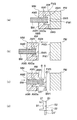
- FIG. 5 is a diagram showing manufacturing steps (a) to (d) of the lens 20. It is sectional drawing of the lens 20 concerning 2nd Embodiment. It is sectional drawing of the lens 20 concerning 3rd Embodiment.
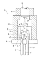
- FIG. 1 is a cross-sectional view in the optical axis direction of the optical communication module 10 according to the first embodiment
- FIG. 2 is a perspective view showing an essential part of the optical communication module 10 in an exploded state.
- a chip mounting portion 13 is attached to the center of a disk-shaped stem 12 having rod-like terminals 11 for feeding power
- a laser chip 15 is attached to the side surface of the chip mounting portion 13 as an optical element via a heat sink 14.
- the laser chip 15 is connected to the terminal 11 via a wiring (not shown).
- a light source used as an optical element a light emitting diode (LED), a laser diode (LD), a vertical cavity surface emitting laser (VCSEL), or the like is used.
- a light receiving element for example, PD (Photo Diode)
- PD Photo Diode
- the lens 20 is arranged so as to cover the outside of the laser chip 15.
- the lens 20 is made of plastic (acrylic, PC, etc.), and includes a lens portion 22 and a cylindrical leg portion 21 extending from the periphery of the lens portion 22 in the optical axis direction (including substantially the optical axis direction) of the lens portion. It is molded integrally. Since the lens 20 is made of plastic, it is more easily broken than a glass lens and is easily affected by temperature.
- the material of the plastic material is not particularly limited as long as the resin has good infrared transmittance, and is an acrylic resin, polycarbonate resin, polyester resin, cycloolefin resin, polysulfone resin, polyethersulfone resin, polyimide resin, Examples include polyetherimide resins, polymethylpentene resins, silicone resins, and epoxy resins. Among these, a cycloolefin resin is preferable from the viewpoint that the optical performance hardly changes due to moisture absorption.
- the leg portions are made of stainless steel, but since the leg portions 21 of the lens 20 are made of plastic, they are easily affected by the use environment.
- the lens 20 is attached to the stem 12 by bonding the end surface 21 b of the leg 21 to the stem (substrate that supports the optical element) 12. Since the lens 20 is made of plastic and the stem 12 is usually gold-plated, the end surface 21b of the leg portion 21 is usually attached by an adhesive without being welded. Further, the end surface 21b of the leg portion 21 may be used as an attachment reference surface when the lens portion 22 is positioned.
- the leg 21 is preferably cylindrical or substantially cylindrical, but may be a polygonal cylinder such as a quadrangle or a pentagon when viewed from the optical axis direction.
- Adhesives include thermosetting adhesives, hot melt adhesives, UV curable adhesives, anaerobic pressure sensitive adhesives, epoxy adhesives, etc., but the effect on the lens during bonding is small. It is preferable to use a UV curable adhesive or an epoxy-based adhesive, and it is desirable to use a highly thixotropic adhesive that has a sufficient adhesive force between the metal system and the resin system and does not spread a liquid.
- the end side of the inner peripheral surface 21a of the leg 21 and the outer peripheral surface 21c are substantially cylindrical surfaces parallel to the optical axis.
- the lens unit 22 has a first optical surface S1 on the laser chip 15 side and a second optical surface S2 on the optical fiber FB side.
- the lens portion 22 side of the inner peripheral surface 21a is a tapered region ST.
- a roughened surface around the second optical surface S2 is preferable because unnecessary light is diffused and the possibility of stray light can be reduced.
- a cylindrical stainless steel holder 30 is attached outside the lens 20 in the direction orthogonal to the optical axis so as to be welded to the stem 12 with a slight gap.
- a cylindrical sleeve 31 having a smaller diameter is fixed to the tip of the holder 30, and a ferrule 32 into which the optical fiber FB is inserted is inserted therein.
- the end of the optical fiber FB faces the lens unit 22. ing.
- the optical communication module 10 of this embodiment When power is supplied through the terminal 11, the laser chip 15 emits light, and the emitted light beam passes through the lens unit 22, is refracted by the refracting surface, and is condensed on the end surface of the optical fiber FB, and then in the optical fiber FB. Will be propagated.
- a diffractive structure for improving temperature characteristics may be provided on the first optical surface S1 or the second optical surface S2. Since plastic lenses for optical communication are used in various temperature environments, optical characteristics may change due to expansion or contraction of the lenses due to temperature changes. By providing, the influence on the optical characteristics due to the expansion or contraction of the lens can be reduced.
- FIGS. 3A to 3D are diagrams showing a manufacturing process of a lens suitable for the above-described embodiment.
- the fixed mold FM has a transfer surface FM1 for transferring the second optical surface S2, and a flat mating surface FM3 around the transfer surface FM1.
- the movable mold MM that is movable with respect to the fixed mold FM has a main mold AM and a nested mold (sub mold) BM.
- the main mold AM and the nested mold (sub mold) BM may be integrated, but are preferably separate from the viewpoint of mold fabrication.
- the main mold AM has a transfer surface AM1 for transferring the inner and outer circumferences of the leg portion 21, a transfer surface AM5 for transferring the end surface 21b of the leg portion 21, a central circular opening AM2, and a plastic material from the outside. It has a gate portion AM3 and a flat mating surface AM4 that faces the mating surface FM3. At this time, the depth of the length in the optical axis direction of the gate portion AM3 is 1.3 mm. If the ratio of the maximum length in the optical axis direction of the lens not including the lens portion to the depth of the gate portion is 2.5: 1 to 1.5: 1, gate cutting can be easily performed, and It is preferable because the filling efficiency is increased.
- the gate portion AM3 is formed by the rectangular cross-section groove formed on the mating surface AM4 of the movable mold MM and the mating surface FM3 with the fixed mold FM, the mating surface FM3 can be a simple plane. This simplifies the structure of the mold.
- the gate portion AM3 communicates with a position corresponding to the outer peripheral surface of the leg portion 21, and is provided toward the lens portion 22 so as not to face a position corresponding to the inner peripheral surface of the leg portion 21. That is, at least a part of the gate portion AM3 overlaps the position in the optical axis direction with respect to the space (lens portion after molding) formed by the transfer surface FM1 and the transfer surface BM1. A part of the space formed by the transfer surface AM1 and the transfer surface AM5 is a part for molding the leg.
- the cylindrical nesting type BM is fitted to the circular opening AM2, is movable with respect to the main mold AM, and has a transfer surface BM1 for transferring the first optical surface S1 at the tip.
- the manufacturing process of a lens suitable for the above-described embodiment will be described.
- the mating surfaces FM3 and AM4 are brought into close contact with each other, and the movable mold MM is fixed to the fixed mold FM. Clamp the mold. In this state, a molten plastic material is injected into the internal cavity through the gate portion AM3.
- the movable mold MM is displaced so as to be integrally moved away from the fixed mold FM.
- the nesting mold BM is relatively moved so as to protrude from the main mold AM.
- the optical surface of the lens 20 that is a molded product is pushed out by the transfer surface BM1, and at this time, the lens 20 has the first point A and the second point B within the ranges of the expressions (1) and (2). Therefore, a sufficient thickness in the vicinity of the base of the leg portion can be secured, and the leg can be stably removed from the main mold AM.
- the molded product is removed from the transfer surface BM1, but since the gate GT ′ solidified in the gate portion AM3 is connected to the molded product, this is cut (C) in the step shown in FIG. Polish the cut surface.
- the lens 20 can be obtained. However, if the cut surface has an acceptable shape, polishing is not necessarily required.
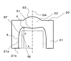
- FIG. 4 is a diagram showing the lens 20 according to the second embodiment.
- the total length H in the optical axis direction of the lens 20 in the present embodiment is 3.5 mm
- the outer diameter D is 4.7 mm
- the optical axis length L of the leg portion 21 is 2 mm
- the width of the leg end surface is 0.2 mm. 4 mm.
- the total length H of the leg-integrated lens for optical communication is 3 to 7 mm
- the outer diameter D is 2 to 6 mm
- the length of the leg 21 in the optical axis direction is 1 to 4 mm
- the width of the leg end face is 0.2 to 0.6 mm.
- the minimum value of the leg width is about 7 to 40% with respect to the length of the leg in the optical axis direction because not only the strength at the base of the leg but also the strength of the entire leg is increased. More preferably, it is 15 to 30%. Since the width of the leg portion is not more than the upper limit, the lens does not become too large, can be adapted to practical use, and can cope with downsizing. Further, the roughness of the inner circumferential surface and the outer circumferential surface of the leg is preferably 1.0 ⁇ m or more and 50 ⁇ m or less in terms of 10-point average roughness in accordance with JIS 0601-1976 (standard for surface roughness).
- the mold release resistance is not so large, the leg is difficult to break at the root, and since it is 1.0 ⁇ m or more, even if light leaking from the light source hits the leg, internal reflection occurs. In addition, since it scatters on the surface, it is difficult to cause stray light.
- the roughness of the leg part in this embodiment is 8 micrometers.
- the length in the optical axis direction of the leg 21 referred to here is the light from the farthest in the optical axis direction from the leg end surface to the leg end surface, excluding the first optical surface, of the inner surface of the lens. Represents the axial distance.
- the lens 20 is obtained by integrally molding a lens portion 22 and a cylindrical leg portion 21 extending from the periphery of the lens portion 22 in the optical axis direction with a plastic material.
- the leg portion may be cylindrical, and the shape when viewed from the optical axis direction may be any shape such as a circular shape, a substantially circular shape, a polygonal shape, or a substantially polygonal shape. In this embodiment, it is substantially circular.
- the lens unit 22 has a first optical surface S1 on the leg side, cuts the lens 20 along a plane including the optical axis, and is on the inner surface of the lens from a point on the optical axis in the first optical surface S1.
- the line which goes to the leg end face along is considered, it has the 1st point A in which the inclination of a tangent changes before and behind within the range of the following formula (1), and within the range of the following formula (2) , A second point B where the slope of the tangent changes before and after that.
- X is the distance in the direction perpendicular to the optical axis from the point farthest from the optical axis to the optical axis of the inner edge of the lens at the end surface of the leg when the optical axis is the zero point
- Y is the end surface of the leg Represents the distance in the optical axis direction from the farthest in the optical axis direction from the leg end surface to the leg end surface, excluding the first optical surface, of the inner surface of the lens.
- the above-mentioned effect becomes still more preferable by satisfy
- 0.70X ⁇ distance in the optical axis vertical direction from the optical axis to the first point A ⁇ 0.85X (3) 0.65Y ⁇ distance in the optical axis direction from the end surface of the leg portion to the second point B ⁇ 0.85Y (4) 0.75X ⁇ distance in the direction perpendicular to the optical axis from the optical axis to the first point A ⁇ 0.82X (5) 0.70Y ⁇ distance in the optical axis direction from the leg end surface to the second point B ⁇ 0.80Y (6)
- the first point A and the second point B exist on the same side with respect to the optical axis.
- the lens 20 since the lens 20 has a small overall length and external shape and has a shape in which the leg portion extends, the lens 20 has a shape in which the leg portion is easily damaged at the time of releasing, but within the range of the formula (1).
- the first point A since the first point A has the second point B within the range of the expression (2), the thickness of the leg portion can be sufficiently secured, and breakage at the time of mold release can be suppressed. Further, since the first point A is within the range of the expression (1) and the second point B is within the range of the expression (2), the lens 20 is adhered to the stem 12 and the optical axis is aligned.
- the mold for molding the lens when the mold for molding the first optical surface and the leg is separate, the first is satisfied by satisfying the formula (1). Since the point A of 1 is sufficiently separated from the optical surface, the thickness of the tip surface of the mold for molding the leg portion can be sufficiently secured, and the mold is less likely to be damaged when the mold is cut or injection molded.
- the space ST is formed by the lens portion and the leg portion, and the shape of the region ST connecting the first point A and the second point B is formed. Since the lens has a concave shape, the non-interference area can be further secured while maintaining the strength of the lens leg portion, and the lens can be reduced in size. Further, when light leaking from the optical element enters the region ST, the incident light goes in a direction away from the optical axis, so that the possibility that the leaked light becomes stray light can be reduced. Further, the first point A and the second point B exist on the same side with respect to the optical axis.
- a plurality of first points A and second points B in the cross-sectional shape including the optical axis of the lens exist on one side of the optical axis for the purpose of maximizing the strength of the leg and the non-interference area NI.
- FIG. 5 is a cross-sectional view of the lens 20 according to the third embodiment.
- This embodiment is a modification of the second embodiment, and parts not specifically described are the same as those of the lens 20 of the second embodiment.
- the shape of the region ST connecting the first point A and the second point B is a straight line. This makes it easy to process the mold and enables low-cost production.
- the inventor changes the distance x in the optical axis direction from the optical axis to the first point A and the distance y in the optical axis direction from the end surface of the leg portion to the second point B.
- the interior space was evaluated.
- the evaluation results are shown in Table 1.
- the evaluation criteria for releasability in the table are as follows. ⁇ : Very good ⁇ : Good ⁇ : Bad
- the evaluation criteria for the size of the internal space are as follows. ⁇ : The internal space is secured with a margin ⁇ : The internal space is secured ⁇ : The internal space is not secured sufficiently
- the lens of the present invention may be used to collect light emitted from an optical fiber on a light receiving element.
- SYMBOLS 10 Optical communication module 11 Terminal 12 Stem 13 Chip mounting part 14 Heat sink 15 Laser chip 20 Lens 21 Leg part 21a Leg inner peripheral surface 21b Leg part end surface 22 Lens part 30 Holder 31 Sleeve 32 Ferrule A First point AM Fixed mold AM Main mold AM1 Transfer surface AM2 Circular opening AM3 Gate portion AM4 Mating surface AM5 Transfer surface B Second point BM Nested BM1 Transfer surface FB Optical fiber FM Fixed mold FM1 Transfer surface FM3 Mating surface GT Gate portion MM Movable mold NI Non Interference area OA Optical axis S1 First optical surface S2 Second optical surface
Landscapes
- Physics & Mathematics (AREA)
- General Physics & Mathematics (AREA)
- Optics & Photonics (AREA)
- Condensed Matter Physics & Semiconductors (AREA)
- Electromagnetism (AREA)
- Optical Couplings Of Light Guides (AREA)
- Led Device Packages (AREA)
- Semiconductor Lasers (AREA)
Abstract
Description
0.60X≦光軸から前記第1の点までの光軸垂直方向の距離≦0.90X (1)
0.60Y≦前記脚部端面から前記第2の点までの光軸方向の距離≦0.90Y (2)
前記第1の点と前記第2の点により結ばれる前記レンズの内面の形状は、前記第1の点と前記第2の点を結ぶ直線形状、又は、前記第1の点と前記第2の点を結ぶ直線よりも凹形状を有しており、前記脚部の光軸方向長に対する前記脚部の幅の最小値が7~40%であるであることを特徴とする。但し、Xは前記光軸をゼロ点とした場合における、前記脚部端面の前記レンズの内面側縁部のうち光軸から最も遠い点から光軸までの光軸垂直方向の距離を、Yは前記脚部端面をゼロ点とした場合における、前記レンズの内面のうち、前記第1の光学面を除いて、前記脚部端面から光軸方向に最も遠いところから前記脚部端面までの光軸方向の距離を表す。
そのため、レンズの小型化にも対応できる。さらに、光源から漏れ出た光が仮に第1の点と第2の点により結ばれる凹形状の領域に入射した場合に、その形状故に入射した光が光軸から離れる方向に向かうので、迷光となる可能性を低減できる。
0.60X≦光軸から前記第1の点Aまでの光軸垂直方向の距離≦0.90X (1)
0.60Y≦前記脚部端面から前記第2の点Bまでの光軸方向の距離≦0.90Y (2)
但し、Xは光軸をゼロ点とした場合における、脚部端面のレンズの内面側縁部のうち光軸から最も遠い点から光軸までの光軸垂直方向の距離を、Yは脚部端面をゼロ点とした場合における、レンズの内面のうち、第1の光学面を除いて、脚部端面から光軸方向に最も遠いところから脚部端面までの光軸方向の距離を表している。また、下記式(3)、(4)を満たすことで上述の効果がより一層好ましいものとなり、下記式(5)、(6)も満たすことでより一層好ましい効果を得ることができる。
0.70X≦光軸から前記第1の点Aまでの光軸垂直方向の距離≦0.85X (3)
0.65Y≦前記脚部端面から前記第2の点Bまでの光軸方向の距離≦0.85Y (4)
0.75X≦光軸から前記第1の点Aまでの光軸垂直方向の距離≦0.82X (5)
0.70Y≦前記脚部端面から前記第2の点Bまでの光軸方向の距離≦0.80Y (6)
また、第1の点Aと第2の点Bは光軸に対して同じ側に存在している。
◎:非常に良い
○:良い
×:悪い
◎:内部空間が余裕を持って確保できている
○:内部空間が確保できている
×:内部空間は十分確保されていない

11 端子
12 ステム
13 チップ搭載部
14 ヒートシンク
15 レーザチップ
20 レンズ
21 脚部
21a 脚部内周面
21b 脚部端面
22 レンズ部
30 ホルダ
31 スリーブ
32 フェルール
A 第1の点
AM 固定金型
AM 主金型
AM1 転写面
AM2 円形開口
AM3 ゲート部
AM4 合わせ面
AM5 転写面
B 第2の点
BM 入れ子型
BM1 転写面
FB 光ファイバー
FM 固定金型
FM1 転写面
FM3 合わせ面
GT ゲート部
MM 可動金型
NI 非干渉領域
OA 光軸
S1 第1の光学面
S2 第2の光学面
Claims (3)
- 光源から出射された光束を集光する光通信用のレンズであって、
前記レンズはプラスチック素材を用いてなり、レンズ部と、前記レンズ部の周辺から前記レンズ部の光軸方向に延在する筒状の脚部とを一体的に成形してなり、
前記レンズ部は脚部側に第1の光学面を有し、
前記レンズを光軸を含む平面で切断し、前記第1の光学面における光軸上の点から、前記レンズの内面に沿って脚部端面に向かう線を考えた場合に、下記式(1)の範囲内において、その前後で接線の傾きが変化する第1の点を有し、下記式(2)の範囲内において、その前後で接線の傾きが変化する第2の点を有し、
0.60X≦光軸から前記第1の点までの光軸垂直方向の距離≦0.90X (1)
0.60Y≦前記脚部端面から前記第2の点までの光軸方向の距離≦0.90Y (2)
前記第1の点と前記第2の点により結ばれる前記レンズの内面の形状は、前記第1の点と前記第2の点を結ぶ直線形状、又は、前記第1の点と前記第2の点を結ぶ直線よりも凹形状を有しており、
前記脚部の光軸方向長に対する前記脚部の幅の最小値が7~40%であることを特徴とする光通信用のレンズ。
但し、Xは前記光軸をゼロ点とした場合における、前記脚部端面の前記レンズの内面側縁部のうち光軸から最も遠い点から光軸までの光軸垂直方向の距離を、Yは前記脚部端面をゼロ点とした場合における、前記レンズの内面のうち、前記第1の光学面を除いて、前記脚部端面から光軸方向に最も遠いところから前記脚部端面までの光軸方向の距離を表す。 - 以下の条件式を満たすことを特徴とする請求項1に記載の光通信用のレンズ。
0.70X≦光軸から前記第1の点までの光軸垂直方向の距離≦0.85X (3)
0.65Y≦前記脚部端面から前記第2の点までの光軸方向の距離≦0.85Y (4) - 請求項1又は2に記載の光通信用のレンズを、光学素子を支持する基板に組み付けてなることを特徴とする光通信モジュール。
Priority Applications (2)
| Application Number | Priority Date | Filing Date | Title |
|---|---|---|---|
| JP2015508262A JPWO2014156630A1 (ja) | 2013-03-26 | 2014-03-12 | 光通信用のレンズ及び光通信モジュール |
| CN201480018038.XA CN105103025A (zh) | 2013-03-26 | 2014-03-12 | 光通信用的透镜以及光通信组件 |
Applications Claiming Priority (2)
| Application Number | Priority Date | Filing Date | Title |
|---|---|---|---|
| JP2013063926 | 2013-03-26 | ||
| JP2013-063926 | 2013-03-26 |
Publications (1)
| Publication Number | Publication Date |
|---|---|
| WO2014156630A1 true WO2014156630A1 (ja) | 2014-10-02 |
Family
ID=51623613
Family Applications (1)
| Application Number | Title | Priority Date | Filing Date |
|---|---|---|---|
| PCT/JP2014/056423 Ceased WO2014156630A1 (ja) | 2013-03-26 | 2014-03-12 | 光通信用のレンズ及び光通信モジュール |
Country Status (3)
| Country | Link |
|---|---|
| JP (1) | JPWO2014156630A1 (ja) |
| CN (1) | CN105103025A (ja) |
| WO (1) | WO2014156630A1 (ja) |
Cited By (1)
| Publication number | Priority date | Publication date | Assignee | Title |
|---|---|---|---|---|
| JP2015164098A (ja) * | 2014-02-28 | 2015-09-10 | コイズミ照明株式会社 | レンズ、及びレンズを備えた照明器具 |
Families Citing this family (3)
| Publication number | Priority date | Publication date | Assignee | Title |
|---|---|---|---|---|
| CN113241587B (zh) * | 2020-01-22 | 2025-06-27 | 瑞识科技(深圳)有限公司 | 一种光学元件及vcsel器件 |
| KR20250105503A (ko) * | 2020-06-11 | 2025-07-08 | 알프스 알파인 가부시키가이샤 | 광학 부품, 및 이것을 사용한 광 모듈 |
| CN114236710A (zh) * | 2021-12-13 | 2022-03-25 | 无锡鑫巨宏智能科技有限公司 | 一种高速耦合透镜 |
Citations (4)
| Publication number | Priority date | Publication date | Assignee | Title |
|---|---|---|---|---|
| JP2004061623A (ja) * | 2002-07-25 | 2004-02-26 | Rohm Co Ltd | イメージセンサモジュールおよびその製造方法 |
| JP2005209840A (ja) * | 2004-01-22 | 2005-08-04 | Konica Minolta Opto Inc | 半導体レーザ装置及び光ピックアップ装置 |
| JP2005259762A (ja) * | 2004-03-09 | 2005-09-22 | Opnext Japan Inc | 半導体レーザモジュール及び光伝送器 |
| JP2006178382A (ja) * | 2004-11-29 | 2006-07-06 | Konica Minolta Holdings Inc | 光学素子、光学素子保持構造、光学素子鏡筒及び光通信モジュール |
Family Cites Families (1)
| Publication number | Priority date | Publication date | Assignee | Title |
|---|---|---|---|---|
| JP4082573B2 (ja) * | 2002-07-01 | 2008-04-30 | ローム株式会社 | イメージセンサモジュール |
-
2014
- 2014-03-12 WO PCT/JP2014/056423 patent/WO2014156630A1/ja not_active Ceased
- 2014-03-12 CN CN201480018038.XA patent/CN105103025A/zh active Pending
- 2014-03-12 JP JP2015508262A patent/JPWO2014156630A1/ja active Pending
Patent Citations (4)
| Publication number | Priority date | Publication date | Assignee | Title |
|---|---|---|---|---|
| JP2004061623A (ja) * | 2002-07-25 | 2004-02-26 | Rohm Co Ltd | イメージセンサモジュールおよびその製造方法 |
| JP2005209840A (ja) * | 2004-01-22 | 2005-08-04 | Konica Minolta Opto Inc | 半導体レーザ装置及び光ピックアップ装置 |
| JP2005259762A (ja) * | 2004-03-09 | 2005-09-22 | Opnext Japan Inc | 半導体レーザモジュール及び光伝送器 |
| JP2006178382A (ja) * | 2004-11-29 | 2006-07-06 | Konica Minolta Holdings Inc | 光学素子、光学素子保持構造、光学素子鏡筒及び光通信モジュール |
Cited By (1)
| Publication number | Priority date | Publication date | Assignee | Title |
|---|---|---|---|---|
| JP2015164098A (ja) * | 2014-02-28 | 2015-09-10 | コイズミ照明株式会社 | レンズ、及びレンズを備えた照明器具 |
Also Published As
| Publication number | Publication date |
|---|---|
| CN105103025A (zh) | 2015-11-25 |
| JPWO2014156630A1 (ja) | 2017-02-16 |
Similar Documents
| Publication | Publication Date | Title |
|---|---|---|
| CN103582837B (zh) | 光插座以及具备该光插座的光模块 | |
| WO2014156630A1 (ja) | 光通信用のレンズ及び光通信モジュール | |
| JP2004239997A (ja) | 光モジュール及びそれを備えた光コネクタ | |
| CN100462758C (zh) | 光学组件及其制造方法 | |
| JP6248934B2 (ja) | 光通信用のレンズ、光通信モジュール及び成形金型 | |
| JPWO2014045850A1 (ja) | 光通信用のレンズ及び光通信モジュール | |
| JP6207881B2 (ja) | 光レセプタクルおよびこれを備えた光モジュール | |
| JP6491418B2 (ja) | 光ファイバコネクタ | |
| JP2014149465A (ja) | 光学部品及びこれを備える光学装置 | |
| JP2014202894A (ja) | 光通信用のレンズユニット及びレンズ | |
| JP2014197086A (ja) | 光通信用モジュール又は光通信ユニット | |
| JP2014195921A (ja) | 光通信用のレンズを成形する金型及び光通信用のレンズ並びに光通信用のレンズの成形方法 | |
| JP2012237819A (ja) | 光モジュール用フォルダ | |
| JP5749592B2 (ja) | 光レセプタクルおよびこれを備えた光モジュール | |
| JP5589740B2 (ja) | 光電変換装置 | |
| JP2014232261A (ja) | 光レセプタクルおよびこれを備えた光モジュール | |
| JP2016103617A (ja) | 光学素子 | |
| JP5817174B2 (ja) | 光学モジュール | |
| JP2007279134A (ja) | プリズム、それを備えた複合光学素子、及びそれを備えた光学装置 | |
| JP5553919B2 (ja) | 光電装置 | |
| JP2004133117A (ja) | 樹脂封止型光モジュール | |
| JP2005326884A (ja) | 光モジュール及びそれを備えた光コネクタ | |
| JP2010191318A (ja) | 光モジュール | |
| JP2007206631A (ja) | 光モジュール | |
| JP2012237820A (ja) | 光モジュールの製造方法 |
Legal Events
| Date | Code | Title | Description |
|---|---|---|---|
| WWE | Wipo information: entry into national phase |
Ref document number: 201480018038.X Country of ref document: CN |
|
| 121 | Ep: the epo has been informed by wipo that ep was designated in this application |
Ref document number: 14775832 Country of ref document: EP Kind code of ref document: A1 |
|
| ENP | Entry into the national phase |
Ref document number: 2015508262 Country of ref document: JP Kind code of ref document: A |
|
| NENP | Non-entry into the national phase |
Ref country code: DE |
|
| 122 | Ep: pct application non-entry in european phase |
Ref document number: 14775832 Country of ref document: EP Kind code of ref document: A1 |