WO2014156436A1 - 変位計測装置及び変位計測システム - Google Patents
変位計測装置及び変位計測システム Download PDFInfo
- Publication number
- WO2014156436A1 WO2014156436A1 PCT/JP2014/054536 JP2014054536W WO2014156436A1 WO 2014156436 A1 WO2014156436 A1 WO 2014156436A1 JP 2014054536 W JP2014054536 W JP 2014054536W WO 2014156436 A1 WO2014156436 A1 WO 2014156436A1
- Authority
- WO
- WIPO (PCT)
- Prior art keywords
- light
- measurement
- displacement
- unit
- measured
- Prior art date
- Legal status (The legal status is an assumption and is not a legal conclusion. Google has not performed a legal analysis and makes no representation as to the accuracy of the status listed.)
- Ceased
Links
Images







Classifications
-
- G—PHYSICS
- G01—MEASURING; TESTING
- G01C—MEASURING DISTANCES, LEVELS OR BEARINGS; SURVEYING; NAVIGATION; GYROSCOPIC INSTRUMENTS; PHOTOGRAMMETRY OR VIDEOGRAMMETRY
- G01C3/00—Measuring distances in line of sight; Optical rangefinders
- G01C3/02—Details
- G01C3/06—Use of electric means to obtain final indication
- G01C3/08—Use of electric radiation detectors
-
- G—PHYSICS
- G01—MEASURING; TESTING
- G01S—RADIO DIRECTION-FINDING; RADIO NAVIGATION; DETERMINING DISTANCE OR VELOCITY BY USE OF RADIO WAVES; LOCATING OR PRESENCE-DETECTING BY USE OF THE REFLECTION OR RERADIATION OF RADIO WAVES; ANALOGOUS ARRANGEMENTS USING OTHER WAVES
- G01S17/00—Systems using the reflection or reradiation of electromagnetic waves other than radio waves, e.g. lidar systems
- G01S17/02—Systems using the reflection of electromagnetic waves other than radio waves
- G01S17/06—Systems determining position data of a target
- G01S17/08—Systems determining position data of a target for measuring distance only
- G01S17/32—Systems determining position data of a target for measuring distance only using transmission of continuous waves, whether amplitude-, frequency-, or phase-modulated, or unmodulated
- G01S17/36—Systems determining position data of a target for measuring distance only using transmission of continuous waves, whether amplitude-, frequency-, or phase-modulated, or unmodulated with phase comparison between the received signal and the contemporaneously transmitted signal
-
- G—PHYSICS
- G01—MEASURING; TESTING
- G01S—RADIO DIRECTION-FINDING; RADIO NAVIGATION; DETERMINING DISTANCE OR VELOCITY BY USE OF RADIO WAVES; LOCATING OR PRESENCE-DETECTING BY USE OF THE REFLECTION OR RERADIATION OF RADIO WAVES; ANALOGOUS ARRANGEMENTS USING OTHER WAVES
- G01S17/00—Systems using the reflection or reradiation of electromagnetic waves other than radio waves, e.g. lidar systems
- G01S17/88—Lidar systems specially adapted for specific applications
-
- G—PHYSICS
- G01—MEASURING; TESTING
- G01S—RADIO DIRECTION-FINDING; RADIO NAVIGATION; DETERMINING DISTANCE OR VELOCITY BY USE OF RADIO WAVES; LOCATING OR PRESENCE-DETECTING BY USE OF THE REFLECTION OR RERADIATION OF RADIO WAVES; ANALOGOUS ARRANGEMENTS USING OTHER WAVES
- G01S7/00—Details of systems according to groups G01S13/00, G01S15/00, G01S17/00
- G01S7/48—Details of systems according to groups G01S13/00, G01S15/00, G01S17/00 of systems according to group G01S17/00
- G01S7/481—Constructional features, e.g. arrangements of optical elements
-
- G—PHYSICS
- G01—MEASURING; TESTING
- G01S—RADIO DIRECTION-FINDING; RADIO NAVIGATION; DETERMINING DISTANCE OR VELOCITY BY USE OF RADIO WAVES; LOCATING OR PRESENCE-DETECTING BY USE OF THE REFLECTION OR RERADIATION OF RADIO WAVES; ANALOGOUS ARRANGEMENTS USING OTHER WAVES
- G01S7/00—Details of systems according to groups G01S13/00, G01S15/00, G01S17/00
- G01S7/48—Details of systems according to groups G01S13/00, G01S15/00, G01S17/00 of systems according to group G01S17/00
- G01S7/481—Constructional features, e.g. arrangements of optical elements
- G01S7/4818—Constructional features, e.g. arrangements of optical elements using optical fibres
-
- G—PHYSICS
- G01—MEASURING; TESTING
- G01S—RADIO DIRECTION-FINDING; RADIO NAVIGATION; DETERMINING DISTANCE OR VELOCITY BY USE OF RADIO WAVES; LOCATING OR PRESENCE-DETECTING BY USE OF THE REFLECTION OR RERADIATION OF RADIO WAVES; ANALOGOUS ARRANGEMENTS USING OTHER WAVES
- G01S7/00—Details of systems according to groups G01S13/00, G01S15/00, G01S17/00
- G01S7/48—Details of systems according to groups G01S13/00, G01S15/00, G01S17/00 of systems according to group G01S17/00
- G01S7/491—Details of non-pulse systems
- G01S7/4912—Receivers
- G01S7/4915—Time delay measurement, e.g. operational details for pixel components; Phase measurement
Definitions
- the present invention relates to a technique of a measuring device that measures distance and displacement.
- the present invention also relates to a suitable measuring device for inspecting social infrastructure such as roads, tunnels, and bridges.
- a measuring device suitable for inspecting social infrastructure such as roads, tunnels, and bridges
- a measuring device that measures the distance to the object to be measured and its displacement using a light source such as a semiconductor laser.
- Patent Document 1 JP-A-3-264886
- Patent Document 2 JP-A-2004-347585
- Patent Document 1 discloses an optical displacement sensor that modulates luminance (also referred to as intensity modulation) of output light from a light emitting unit at a specific frequency, and calculates the phase difference between the phase of reflected light from a measurement object and the phase of reference light. An apparatus for measuring the distance and displacement to a measurement object is described.
- luminance also referred to as intensity modulation
- Patent Literature 2 is a building and civil engineering structure measurement / analysis system that is mounted on a measurement vehicle and stores a movement distance, an azimuth angle of a laser range finder, an elevation angle, and a distance to a measurement point in association with each other. A system for measuring wall surfaces is described.
- Non-Patent Document 1 describes a liquid lens in which two liquids that are not mixed with each other are brought into contact with each other through an opening, and the curvature of the two-liquid interface is changed by controlling the pressure of one of the liquids, thereby changing the focal distance. Has been. The response of this liquid lens is as fast as 1 ms or less.
- the conventional displacement measuring apparatus has the following problems concerning the accuracy of distance and displacement measurement.
- An optical displacement sensor that is a laser distance measuring device of Patent Document 1 measures reflected light from a measurement object. For this reason, when the reflected light from the object to be measured is scattered as in the case where the object to be measured is a tunnel wall surface, the detected light amount decreases. As a result, the SNR (Signal to noiseatioratio) of the luminance modulation waveform is deteriorated, and sufficient accuracy regarding the distance and displacement of the measurement object cannot be obtained.
- the accuracy of measuring the displacement is proportional to the SNR, and the SNR is proportional to the square root of the light intensity.
- the laser range finder using luminance modulation which is a general method, including the example of Patent Document 1, currently has a displacement measurement accuracy of about 2 mm at the maximum.
- the accuracy for measuring a displacement of about 5 to 10 mm is required as the displacement. That is, the accuracy of the displacement measurement needs to be about 1/10 of the displacement. For example, in order to measure a displacement of 5 mm, an accuracy of 0.5 mm is required.
- a current displacement measuring device such as a laser distance measuring device is insufficient in accuracy to measure the displacement of about 5 to 10 mm.
- the conventional displacement measuring device has a problem that it affects the measurement accuracy according to the distance between the sensor surface of the displacement measuring device and the object to be measured.
- the object to be measured is a tunnel wall surface
- a method of measuring the displacement of the tunnel wall surface while traveling by a moving vehicle equipped with a displacement measuring device such as a laser distance measuring device can be cited as in the example of Patent Document 2.
- a moving vehicle irradiates measurement light by a laser in a direction perpendicular to the traveling direction of the moving vehicle while traveling on one side of a lane in the tunnel, and the distance to the tunnel wall and its displacement are reflected by the reflected light.
- a method of measuring In the case of the above-described method, the wall surface on the own lane side is close, but the wall surface on the opposite lane side is far from the sensor surface of the displacement measuring device. If the scattering angle from both the wall surfaces is constant, the spread of the reflected scattered light on the sensor surface increases as the distance between the sensor surface and the wall surface increases. As a result, the amount of light detected on the sensor surface decreases, and the accuracy of distance and displacement measurement decreases.
- the conventional displacement measuring device has a problem that the measurement accuracy is lowered due to the influence of noise caused by vibration of the displacement measuring device.
- the measurement is performed while the displacement measuring device is mounted on the moving vehicle. Therefore, noise is superimposed on the measurement data due to the vibration of the moving vehicle. For this reason, it is difficult to detect the displacement amount of the tunnel wall surface, in particular small scratches, with the measurement data on which the noise is superimposed.
- An object of the present invention is to provide a technique capable of improving the accuracy of distance and displacement measurement regarding a displacement measuring apparatus.
- a representative embodiment of the present invention is a displacement measuring device, a displacement measuring system, and the like, and has the following configuration.
- a displacement measuring device includes: a light source unit that outputs light whose intensity is modulated based on a periodic signal; an optical amplifier that amplifies and outputs light from the light source unit; An optical system that irradiates light to the object to be measured and receives the reflected light, a measurement light detection unit that detects reflected light from the object to be measured as measurement light, a phase of the signal of the measurement light, and the light A phase comparison unit that compares the phase of the signal of the reference light based on the light from the amplifier, and a displacement calculation unit that calculates the distance to the measurement object and the displacement of the measurement object based on the result of the phase comparison And having.
- the optical amplifier includes an excitation unit that outputs light for amplifying the light from the light source unit, a multiplexing unit that combines the light from the light source unit and the light from the excitation unit, And an optical waveguide for amplifying light from the multiplexing unit.
- the optical amplifier has two or more stages of optical amplifiers connected in series.
- the optical system includes a condensing lens that condenses the light from the optical amplifier onto the measurement object, and the measurement object includes the measurement light detection unit.
- a condensing lens or a measuring light detecting lens is formed of a variable focus lens, and has a focus control unit that controls a focal length of the variable focus lens.
- the wavelength of light output from the light source unit is, for example, a first wavelength in the range of 1000 to 1100 nm, or a second wavelength in the range of 1500 to 1650 nm, and the excitation of the optical amplifier
- the wavelength of the light output from the unit is a first excitation wavelength near 980 nm corresponding to the first wavelength, a first excitation wavelength near 980 nm corresponding to the second wavelength, or a second excitation wavelength near 1480 nm. Is the wavelength.
- a displacement measurement system includes a displacement measurement device that measures a distance to an object to be measured and a displacement of the object to be measured, and the displacement measurement device, and moves relative to the object to be measured. And a position measuring unit that measures a position or a moving distance of the moving vehicle.
- the displacement measuring device includes a light source unit that outputs light whose intensity is modulated based on a periodic signal, an optical amplifier that amplifies and outputs light from the light source unit, and light from the optical amplifier to a measurement object.
- An optical system that irradiates and reflects the reflected light; and a rotating mirror that is disposed downstream of the optical system and that irradiates the object to be measured with the light from the optical amplifier and enters the reflected light into the optical system.
- a rotation angle detector that detects a rotation angle of the rotating mirror, a measurement light detector that detects reflected light from the object to be measured as measurement light, a phase of the signal of the measurement light, and the optical amplifier
- a phase comparison unit that compares a phase of a signal of reference light based on light, a displacement calculation unit that calculates a distance to the measurement object and a displacement of the measurement object based on a result of the phase comparison, and Rotation angle information, distance to the object to be measured And displacement information, and using the position or information of the movement distance of the moving vehicle, having a profile creating unit that creates a three-dimensional profile data of the object to be measured.
- the displacement measurement system includes an acceleration measurement unit that measures the acceleration of the mobile vehicle, and the profile creation unit uses the information on the acceleration of the mobile vehicle and uses the acceleration information for each rotation angle in the profile data. Correct distance and displacement data.
- the displacement measurement apparatus uses a storage unit that stores three-dimensional profile data of the measurement object for each measurement date and time, and profile data for each measurement date and time to obtain a difference between profile data of different measurement dates and times.
- a difference calculation unit that calculates, compares the difference with the management value, and outputs a result of the comparison.
- the optical system includes a condenser lens that condenses the light from the optical amplifier onto the measurement object, and a measurement light detection lens that forms an image of the measurement object on the measurement light detection unit.
- the measurement light detection lens or the condensing lens is configured by a variable focus lens, and the displacement measurement device includes a focus control unit that controls a focal length of the variable focus lens using information on the rotation angle. Have.
- the accuracy of distance and displacement measurement can be improved with respect to the displacement measuring device.
- FIG. 3 is a diagram illustrating a configuration of an optical amplifier in the displacement measuring apparatus according to the first embodiment. It is a figure which shows the structure of the displacement measuring device of the modification of Embodiment 1.
- FIG. It is a figure which shows the example of a periodic signal in the displacement measuring device of Embodiment 1.
- FIG. 3 is a diagram illustrating a design example such as a frequency of a periodic signal, a wavelength of a light source, and a wavelength of an optical amplifier in the displacement measuring apparatus of the first embodiment. It is a figure which shows the low frequency signal and high frequency signal of measurement light in the displacement measuring device of Embodiment 1.
- FIG. 1 It is a figure which shows the low frequency signal and high frequency signal of reference light in the displacement measuring device of Embodiment 1. It is a figure which shows the example of the phase comparison of the low frequency signal of measurement light, and the low frequency signal of reference light in the displacement measuring device of Embodiment 1.
- FIG. It is a figure which shows the example of the signal of measurement light in the conventional displacement measuring device when there is little reflected light of the measurement object surface. It is a figure which shows the example of the signal of the measurement light at the time of amplifying 20 times with the optical amplifier in the displacement measuring device of Embodiment 1.
- FIG. It is a figure which shows the structure of the displacement measuring device of Embodiment 2.
- FIG. It is a figure which shows the structure of the displacement measuring device of Embodiment 3.
- FIG. 10 is a diagram illustrating an example of alignment of a three-dimensional profile in a fourth embodiment.
- FIG. 20 is a diagram illustrating an example of a difference calculation of a three-dimensional profile in the fourth embodiment.
- the displacement measuring apparatus 100 according to the first embodiment will be described with reference to FIGS.
- the displacement measuring apparatus 100 according to the first embodiment shows a form applied to a laser distance measuring apparatus using an intensity modulation method using a laser diode as the light source 2.
- the displacement measuring apparatus 100 according to the first embodiment is a laser distance measuring apparatus having an optical amplifier 20.
- the displacement measuring apparatus 100 according to the first embodiment can measure the distance to the object to be measured and the displacement of the object to be measured, and can be suitably used for inspection of social infrastructure such as roads, tunnels, and bridges. .
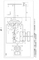
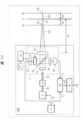
- FIG. 1 shows a configuration including a displacement measuring apparatus 100 according to the first embodiment.
- FIG. 1 includes the measurement target surface 5 that is the object to be measured, and the actual distance, size, and the like are omitted.
- FIG. 1 has X and Y as a direction and coordinate system on description. In the X direction, an example is shown in which the distance D1 between the displacement measuring device 100 and the measurement target surface 5 and the displacements d1 to d2 of the measurement target surface 5 that are the differences between the distances D1 are measured.
- the displacement measuring apparatus 100 includes an intensity modulation unit 10, a light source 2, an optical fiber 25, an optical amplifier 20, an optical fiber 26, an optical system 3, a phase comparison unit 70, and a displacement calculation unit 80. These units are in the order. Connected with.
- the intensity modulation unit 10 is a part that generates a periodic signal by an intensity modulation method, and includes a fundamental frequency oscillator 11, a low multiplication converter 12, and a high multiplication converter 13.
- the fundamental frequency oscillator 11 oscillates a fundamental frequency signal s 1, and the signal s 1 is sent to the low multiplication converter 12 and the high multiplication converter 13.
- the low multiplication converter 12 outputs a signal s2 which is a low frequency periodic signal obtained by converting the frequency of the signal s1 to low multiplication.
- the high multiplication converter 13 outputs a signal s3 which is a high frequency periodic signal obtained by converting the frequency of the signal s1 to high multiplication.
- a signal s4 obtained by combining the signal s2 and the signal s3 is input to the light source 2.
- the light source 2 receives the signal s4, which is a periodic signal from the intensity modulation unit 10, and outputs the intensity-modulated light based on the signal s4 to the optical fiber 25.
- the optical fiber 25 propagates the signal s 5 of the output light from the light source 2 and inputs it to the optical amplifier 20.
- the light source 2 uses a direct modulation method using a laser diode.
- the laser diode inputs a modulation signal and outputs modulated light.
- the light source 2 is not limited to a laser diode, and other means and methods can be applied.
- the optical amplifier 20 receives the output light from the light source 2 from the optical fiber 25 and outputs the light amplified inside the optical amplifier 20 to the optical fiber 26.
- the optical fiber 26 propagates an amplified light signal s 6 that is output light from the optical amplifier 20.
- the optical fiber 25 and the optical fiber 26 are composed of a core, a clad, a protective film, and the like.
- the signal s6 of the amplified light from the optical amplifier 20 enters the optical system 3 through the optical fiber 26.
- the optical system 3 irradiates the measurement target surface 5 that is the object to be measured with the amplified light from the optical amplifier 20 and enters the reflected light.
- the optical system 3 includes a collimator lens 31, a beam splitter 32, a condenser lens 33, a measurement light detection lens 34, a reference light detection lens 35, a measurement light detection unit 61, and a reference light detection unit 62. Including.
- the collimating lens 31 turns the light a1 from the optical fiber 26 into collimated light a2 that is light adjusted in a parallel state.
- the beam splitter 32 separates measurement light and reference light.
- the condensing lens 33 condenses the output light of the optical system 3 on the measurement target surface 5.
- the condensing lens 33 turns the collimated light into light a ⁇ b> 3 that is condensed on the measurement target surface 5.
- the measurement light detection lens 34 enters the collimated light and focuses it on the point p3 of the measurement light detection unit 61.
- the measurement light detection lens 34 forms an image of the point p2 on the measurement target surface 5 that is the object to be measured, on the point p3 that is the light receiving unit of the measurement light detection unit 61.
- the reference light detection lens 35 receives collimated light and collects it at a point p4 that is a light receiving unit of the reference light detection unit 62.
- the reference light detection lens 35 images the emission point p0 of the optical fiber 26 at a point p4 of the reference light detection unit 62.
- the measurement light detector 61 receives and detects reflected light from the measurement target surface 5 as measurement light.
- the reference light detector 62 receives and detects reference light based on the light from the optical amplifier 20.
- emits the light in the displacement measuring device 100 and the optical system 3, and injects reflected light is also called sensor surface on description.
- the sensor surface corresponds to the condenser lens 33 of the optical system 3.
- the position serving as the reference is not limited to the position of the condensing lens 33 serving as the sensor surface, and the position of the measurement light detection unit 61 and the like is calculated by correction calculation. It can be.
- the flow of light in the optical system 3 is as follows.
- the amplified light signal s 6 from the optical amplifier 20 is diffused as light a 1 in the X direction from the emission point p 0 on the end face of the optical fiber 26 and is incident on the collimating lens 31.
- the light a1 becomes collimated light a2 by the collimating lens 31.
- the collimated light a2 is incident near the point p1 of the beam splitter 32.
- a component other than a part passes through the beam splitter 32.
- the collimated light that has passed through the beam splitter 32 enters the condenser lens 33, is condensed by the condenser lens 33, and is emitted.
- the light a3 emitted from the condenser lens 33 enters the point p2 on the measurement target surface 5 existing in the X direction.
- the light reflected by the measurement target surface 5 is incident on the optical system 3 from the condenser lens 33 again.
- the light incident on the condenser lens 33 becomes collimated light, is incident again near the point p1 of the beam splitter 32, and is reflected upward in the Y direction.
- the reflected light is collected by the measurement light detection lens 34 and then incident on the point p3 of the measurement light detection unit 61 and detected as measurement light.
- some components of the collimated light a2 based on the light a1 are separated by being reflected by the beam splitter 32 downward in the Y direction.
- the reflected light is collected by the reference light detection lens 35 and then incident on the point p4 of the reference light detection unit 62 to be detected as reference light.
- the phase comparison unit 70 receives the measurement light signal s11 output from the measurement light detection unit 61 and the reference light signal s12 output from the reference light detection unit 62.
- the phase comparison unit 70 frequency-separates the signal s11 from the measurement light detection unit 61 and the signal s12 from the reference light detection unit 62. That is, these signals are separated into a high frequency signal and a low frequency signal for comparison.
- the phase comparison unit 70 inputs a separation unit 71 that frequency-separates the signal s11 from the measurement light detection unit 61, a separation unit 72 that frequency-separates the signal s12 from the reference light detection unit 62, and a signal after each separation. And a phase comparator for phase comparison.
- the phase comparison unit 70 compares the phase of the measurement light signal s11 with the phase of the reference light signal s12 and outputs a signal s13 as a result of the comparison.
- the displacement calculation unit 80 receives the signal s13 from the phase comparison unit 70, calculates the distance D1 to the measurement target surface 5 and the displacements d1 to d2 of the measurement target surface 5 based on the phase comparison result, and calculates the calculation.
- the result is output as signal s14.
- FIG. 2 shows a configuration example of the optical amplifier 20.
- the optical amplifier 20 includes an optical fiber 25, a pump laser diode 21, an optical fiber 22, a multiplexer 23, a doped fiber 24, and an optical fiber 26.
- an optical fiber 25 and an optical fiber 22 connected to the pump laser diode 21 are connected to the input side, and a doped fiber 24 is connected to the output side.
- An optical fiber 26 is connected to the output side of the doped fiber 24.
- the signal s5 of the emitted light from the laser diode that is the light source 2 is propagated through the optical fiber 25 and enters the optical amplifier 20.
- a signal from the optical fiber 25 enters the multiplexer 23.
- the light emitted from the pump laser diode 21 is propagated through the optical fiber 22 and enters the multiplexer 23.
- the multiplexer 23 enters the doped fiber 24 with light obtained by combining light from the laser diode that is the light source 2 and light from the excitation laser diode 21.
- the doped fiber 24 is an optical fiber doped with a rare earth component, and constitutes an optical waveguide for light amplification.
- the doped fiber 24 is an optical fiber doped with ytterbium (Yb) or an optical fiber doped with erbium (Er).
- the optical amplifier 20 passes light from the light source 2 through the doped fiber 24 and is excited by the pump laser diode 21 for amplification.
- the excitation laser diode 21 amplifies light from the laser diode that is the light source 2 by exciting ions of the doped element in the doped fiber 24.
- the amplification factor obtained by the optical amplifier 20 having the configuration of FIG. 2 is about 10 times. Further, the amplification factor of 20 times can be obtained by connecting the optical amplifiers 20 in two stages in series. Similarly, a configuration in which a large amplification factor of 30 times or more can be obtained by connecting the optical amplifiers 20 in three or more stages.
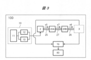
- FIG. 3 shows a configuration in which the optical amplifier 20A, which is the two optical amplifiers 20, and the optical amplifier 20B are connected by the optical fiber 27 in the displacement measuring apparatus 100 according to the modification of the first embodiment. Thereby, the light from the light source 2 can be emitted to the optical system 3 with an amplification factor of 20 times. Not only the configuration of FIG. 3 but also a configuration in which two or more stages of optical amplifiers 20 are connected in series between the light source 2 and the optical system 3 is possible.
- FIG. 4 shows an example of a periodic signal generated by the intensity modulation unit 10 in the first embodiment.
- the horizontal axis represents time, and the vertical axis represents signal intensity or phase.
- a signal 401 shown on the upper side indicates a low-frequency signal having a low frequency corresponding to the signal s ⁇ b> 2 generated by the low multiplication converter 12.
- a periodic signal 402 shown on the lower side indicates a high-frequency signal corresponding to the signal s3 generated by the high multiplication converter 13.
- the low frequency signal 401 is 15 MHz and the high frequency signal 402 is 300 MHz.
- the signal 401 that is a low frequency signal and the signal 402 that is a high frequency signal are combined.
- the combined signal s4 is input to the laser diode as the light source 2 as a current or voltage signal.
- FIG. 5 shows the design of the wavelength of the light source 2 and the wavelength of the excitation laser diode 21 of the optical amplifier 20 in the first embodiment.
- the frequency of the periodic signal of the intensity modulator 10 and the wavelength of the output light of the laser diode that is the light source 2 are matched to the wavelength of the output light of the pump laser diode 21 of the optical amplifier 20 and the characteristics of amplification by the doped fiber 24. Designed.
- the laser diode as the light source 2 emits a continuous wave having a first wavelength of, for example, 1060 nm or a second wavelength of 1550 nm as a continuous wave.
- the intensity of the continuous wave changes according to the low frequency signal 401 and the high frequency signal 402 shown in FIG.
- the displacement measuring apparatus 100 of Embodiment 1 obtains an amplification factor of 10 to 20 times by the optical amplifier 20.
- the configuration shown in FIG. 1 is used when the amplification factor is 10 times
- the configuration shown in FIG. 3 is used when the amplification factor is 20 times.
- a Yb-doped fiber or an Er-doped fiber is used as the doped fiber 24 in order to obtain an amplification factor of 10 to 20 times.
- the wavelength of the output light of the light source 2 corresponding to the Yb-doped fiber is designed to be a first wavelength of 1000 to 1100 nm, for example, 1060 nm.
- the wavelength of the output light of the light source 2 corresponding to the Er-doped fiber is designed to be a second wavelength of 1500 to 1650 nm, for example, 1550 nm.
- the wavelength of the laser diode as the light source 2 is 1000 to 1100 nm which is the first wavelength
- the wavelength of the light of the pump laser diode 21 is around 980 nm (about 980 ⁇ 5 nm) as the first pump wavelength. Is selected.
- the wavelength of the laser diode that is the light source 2 is 1500 to 1650 nm, which is the second wavelength
- the wavelength of the light of the excitation laser diode 21 is about 980 nm or 1480 nm (about 1480 ⁇ 5 nm) as the second excitation wavelength. Is selected.
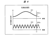
- [Measurement light signal and reference light signal] 6 shows the low-frequency signal 601 and the high-frequency signal 602 after frequency separation in the phase comparison unit 70 in the measurement light signal s11 detected by the measurement light detection unit 61, as in FIG.
- a point 601a indicating the signal intensity or phase in the low frequency signal 601 and a point 602a indicating the signal intensity or phase in the high frequency signal 602 are shown at a certain time t1 corresponding to the measurement date and time.
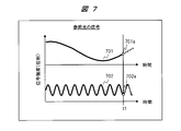
- FIG. 7 shows the low-frequency signal 701 and the high-frequency signal 702 after the frequency separation in the phase comparison unit 70 in the reference light signal s12 detected by the reference light detection unit 62, as in FIG. 6 shows a point 701a indicating the signal intensity or phase in the low frequency signal 701 and a point 702a indicating the signal intensity or phase in the high frequency signal 702 at a certain time t1 corresponding to the same measurement date and time as in FIG.
- the phase comparison unit 70 compares the phases of the measurement light signal in FIG. 6 and the reference light signal in FIG. 7 at the same time, and detects the phase difference. At this time, the phase comparison unit 70 compares the phases of the low frequency signals and the high frequency signals.
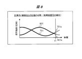
- FIG. 8 shows a phase comparison example.
- the phase comparison unit 70 detects a phase difference between the point 601a of the low-frequency signal 601 of the measurement light in FIG. 6 and the point 701a of the low-frequency signal 701 of the reference light in FIG.
- the displacement calculation unit 80 calculates the distance D1 and the displacements d1 and d2 to the measurement target surface 5 based on the phase difference.
- the distance from the sensor surface of the displacement measuring apparatus 100 to the measurement target surface 5 is L
- the wavelength of the intensity modulation signal is ⁇
- the wave number is n.
- n 2L / ⁇ (Formula 1).
- the distance error corresponding to the measurement accuracy is ⁇ L
- the distance L to the measurement target surface 5 is set to a maximum of 20 m assuming a distance at the time of measurement of the tunnel wall surface, for example.
- FIG. 9 shows a measurement light signal 901 when the reflected light on the measurement target surface is small in the conventional displacement measurement apparatus.
- This measurement light signal 901 is largely superimposed with shot noise as shown in the figure. For this reason, it is difficult for the conventional displacement measuring device to detect the phase with high accuracy when the measurement light signal 901 is used.
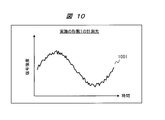
- FIG. 10 shows a signal of measurement light by the measurement light detector 61 in the displacement measurement apparatus 100 of the first embodiment, particularly when the amplification factor is 20 times due to the configuration of the two-stage optical amplifier 20 of FIG. 1001 is shown.
- the measurement light signal 1001 has less noise than the measurement light signal 901 shown in FIG. That is, according to Embodiment 1, it can be seen that the accuracy of phase detection is improved.
- the light emitted from the light source 2 is intensity-modulated by adding the low-frequency signal 401 (s2) and the high-frequency signal 402 (s3) from the intensity modulator 10 to the laser diode that is the light source 2.
- the method of intensity modulation is not limited to the above.
- the light emitted from a laser diode that is the light source 2 is incident on acousto-optic modulators (Acoust Modulators) and electro-optic modulators (Electro-Optic Modulators), which are known techniques, and low frequency signals 401 are input to these modulators.
- intensity modulation may be performed by adding the high-frequency signal 402. That is, as a modification of the first embodiment, a configuration in which an intensity modulation unit including the modulator is provided between the light source 2 and the optical amplifier 20 is possible.
- the displacement measuring apparatus according to the second embodiment will be described with reference to FIG.
- the displacement measuring apparatus according to the second embodiment is a laser distance measuring apparatus in which a variable focus lens is introduced.
- the second embodiment has a configuration in which the measurement light detection lens 34 shown in FIG.
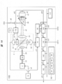
- FIG. 11 shows a configuration including the displacement measuring apparatus 100 of the second embodiment.
- the displacement measuring apparatus 100 according to the second embodiment includes a variable focus lens 37, a focus control unit 170, a focus control amount storage unit 171 and the like in the optical system 3 as elements different from the first embodiment.
- the sensor surface of the displacement measuring apparatus 100 and the measurement target surface 5 are placed in an imaging relationship in order to be able to flexibly cope with a change in the distance to the measurement target surface 5 that is the object to be measured.
- a variable focus lens 37 is used as a component of the optical system 3.
- the variable focus lens 37 forms an image of the reflected light from the measurement target surface 5 at a point p3 of the measurement light detector 61.
- the variable focus lens 37 is a lens that can change the focal distance at high speed based on the control from the focus control unit 170.
- a variable focus lens 37 for example, a liquid lens is used. Details of the liquid lens are described in Non-Patent Document 1 described above.
- the displacement measuring apparatus 100 varies the focal length of the variable focus lens 37 in response to a change in the distance D1 to the measurement target surface 5 due to, for example, movement of the object to be measured or movement of the displacement measuring apparatus 100 itself.
- the change in the position of the measurement target surface 5 in the X direction is indicated by distances D2 and D3.
- the distances D2 and D3 are different from the displacements d1 and d2 in FIG.
- the distance D1 to the measurement target surface 5 similar to FIG. 1 is used as a reference.
- the measurement target surface 51 shows a case where the measurement target surface 51 is moved from the position of the reference distance D1 to a position closer to the front side in the X direction by the distance D2.
- the measurement target surface 52 shows a case where the measurement target surface 52 has moved from the position of the reference distance D1 to a position farther away by the distance D3 on the far side in the X direction.
- the measurement target surface 5 is a tunnel wall surface
- the distance to the tunnel wall surface changes according to the position of the displacement measuring device 100 in the tunnel.
- the focus control unit 170 is connected to the variable focus lens 37, the measurement light detection unit 61, and the focus control amount storage unit 171.
- the focus control unit 170 applies a signal based on voltage or current to the variable focus lens 37. Thereby, the focal length of the variable focus lens 37 is controlled.
- a51 indicates the light when the focal point is focused on the point p2a of the measurement target surface 51.
- a52 indicates light when the focal point is imaged at the point p2b of the measurement target surface 52.
- the focus control amount storage unit 171 stores a control amount for the focus control.
- This control amount includes, for example, information on the correspondence between the distance between the sensor surface of the displacement measuring apparatus 100 and the measurement target surface 5 and the voltage or current value as the control amount for the focus control.
- the focus control amount may be set in advance in the focus control amount storage unit 171 of the displacement measuring apparatus 100, or may be set by the user with respect to the focus control unit 170 and the focus control amount storage unit 171. Further, the focal length of the variable focus lens 37 can be adjusted through the focus control unit 170 by the user's manual operation as required by the user.
- the displacement measuring apparatus 100 changes the focal length of the variable focus lens 37 by the focus control unit 170 in response to the change of the position of the measurement target surface 5 as in the example of FIG.
- the measurement target surface is imaged at a point p3 of the measurement light detector 61.
- the measurement light detector 61 can always receive the measurement light with sufficient reflected light. Thereby, the accuracy of distance and displacement measurement using the measurement light can be increased.
- the second embodiment even when the distance between the sensor surface of the displacement measuring device 100 and the measurement target surface 5 changes to some extent as a measurement situation due to the configuration including the variable focus lens 37, Variations in the amount of light detected on the sensor surface due to the above-described reflected and scattered light can be reduced. Therefore, according to the second embodiment, even when the distance changes to some extent as described above, it is possible to flexibly cope with the measurement and to keep the measurement accuracy stable.
- Embodiment 3 A displacement measuring apparatus according to the third embodiment will be described with reference to FIG.
- the displacement measuring apparatus according to the third embodiment is a laser distance measuring device in which a variable focus lens is introduced.
- Embodiment 3 has a configuration in which the condenser lens 33 in FIG.
- FIG. 12 shows a configuration including the displacement measuring apparatus 100 of the third embodiment.
- the displacement measurement apparatus 100 according to the third embodiment includes a variable focus lens 38, a focus control unit 170, a focus control amount storage unit 171 and the like in the optical system 3 as elements different from the first embodiment.
- the displacement measuring apparatus 100 not only forms an image of the reflected light from the measurement target surface 5 on the point p3 of the measurement light detection unit 61 by the configuration in which the condenser lens 33 is the variable focus lens 38,
- the irradiation light to the measurement target surface 5 can also be condensed according to the change in the position of the measurement target surface 5. Therefore, Embodiment 3 can further increase the amount of measurement light detected by the measurement light detector 61. Therefore, Embodiment 3 can further improve the accuracy of laser distance measurement.
- a displacement measurement system 300 according to the fourth embodiment will be described with reference to FIGS.
- a displacement measurement system 300 according to the fourth embodiment shows a configuration of a profile measurement system configured by mounting a laser distance measuring device which is the displacement measurement device 100 on a moving vehicle 200.
- the displacement measurement device 100 constituting the displacement measurement system 300 of the fourth embodiment includes all the components and functions of the displacement measurement device 100 of the second embodiment described above, and the components and functions unique to the fourth embodiment. Is provided. That is, the fourth embodiment includes the above-described optical amplifier 20, variable focus lens 37, displacement calculator 80, and the like.
- a tunnel wall surface 50 is used as an example of the measurement target surface 5 that is an object to be measured, and an example in which the displacement of the tunnel wall surface 50 is measured while traveling by the moving vehicle 200 will be described.
- the displacement measurement system 300 according to the fourth embodiment has a function of measuring the profile of the tunnel wall surface 50 as a profile measurement system.
- This profile is a profile showing the shape of the tunnel wall surface 50 by measuring the distance and displacement in the three-dimensional space.
- this profile is a profile including the change of the shape of the tunnel wall surface 50 on the time axis according to the measurement date.
- FIG. 13 shows a schematic configuration of a displacement measurement system 300 according to the fourth embodiment.
- a displacement measurement system 300 according to the fourth embodiment includes a mobile vehicle 200 and a displacement measurement device 100 mounted on the mobile vehicle 200.
- the moving vehicle 200 includes a position measurement unit 201 and an acceleration sensor 202.
- the moving vehicle 200 travels on the ground 9 in the Z direction, for example.
- FIG. 13 has a tunnel wall surface 50 as a measurement target surface that is an object to be measured, and is illustrated on the upper side in the Y direction of the moving vehicle 200 and the displacement measuring device 100. Note that X, Y, and Z are shown as directions and coordinate systems for explanation.
- the traveling direction of the moving vehicle 200 is defined as the Z direction, and the directions that form a plane perpendicular to the Z direction are defined as the X direction and the Y direction.
- the X direction is a horizontal direction with respect to the ground 9
- the Y direction is a vertical direction with respect to the ground 9.
- the moving vehicle 200 moves in the Z direction with respect to the tunnel wall surface 50 that is the object to be measured.
- the moving vehicle 200 has the displacement measuring device 100 mounted on the upper surface of the vehicle body, for example.
- the position measurement unit 201 is a part that measures the position or travel distance of the mobile vehicle 200, and is, for example, a travel distance sensor that calculates a travel distance based on the number of rotations of the wheels of the mobile vehicle 200.
- the position measuring unit 201 measures at least the position or travel distance in the Z direction of the moving vehicle 200. Information on the position or travel distance measured by the position measurement unit 201 is sent to the profile calculation unit 130 as a signal s31.
- the acceleration sensor 202 measures the acceleration (referred to as ⁇ ) of the moving vehicle 200 as the acceleration ⁇ in the three-dimensional space of the time axis and X, Y, and Z. Information on the acceleration ⁇ measured by the acceleration sensor 202 is sent to the correction calculation unit 120 as a signal s32.
- the displacement measuring apparatus 100 includes a rotating mirror 36, a drive system 41, a rotary encoder 42, a control unit 110, a correction calculation unit 120, a profile calculation unit 130, a difference calculation unit 140, An output unit 150, a storage unit 160, and the like are included.
- the rotating mirror 36 is disposed at a position between the optical system 3 and the tunnel wall surface 50 which is a measurement target surface, particularly at a position in front of the Z direction, which is a rear stage of the condenser lens 33 of the optical system 3.
- the rotating mirror 36 enters the light a3 emitted from the condenser lens 33 of the optical system 3 in the vicinity of the point p6, and reflects it in the Y direction on the surface of the 45-degree mirror including the point p6 on the YZ plane.
- the light a ⁇ b> 3 incident on the rotary mirror 36 is reflected upward in the Y direction, and the reflected light a ⁇ b> 6 is applied to the point p ⁇ b> 7 on the tunnel wall surface 50.
- the light reflected at the point p7 on the tunnel wall surface 50 is reflected again by the rotating mirror 36, becomes light in the Z direction, and enters the condenser lens 33 of the optical system 3.
- the drive system 41 drives the rotary mirror 36 to rotate around the Z axis.
- This rotation angle is represented by ⁇ .
- This rotation continues 360 ° rotation at a constant angular velocity.
- the light a6 that is the condensed light to the tunnel wall surface 50 that is the measurement target surface is rotated 360 degrees in the XY plane.
- the trajectory of the point where the tunnel wall surface 50 is irradiated with light by the rotation of the rotating mirror 36 becomes a trajectory in the XY plane.
- the locus of the point of the irradiation light on the object to be measured becomes a locus in the three-dimensional space of X, Y, and Z. Note that the above rotation is not limited to the rotation of the angle ⁇ in the XY plane perpendicular to the Z direction, depending on the configuration of the rotating mirror 36 and the drive system 41, and is similarly possible.
- the drive system 41 is provided with a rotary encoder 42.
- the rotary encoder 42 is a rotation angle detector, measures and detects the rotation angle ⁇ of the rotary mirror 36, and outputs a signal s41 and a signal s42 of the rotation angle ⁇ .
- One signal s41 is input to the focus control unit 170 described above.
- the other signal s42 is input to the correction calculation unit 120.
- the focus control unit 170 controls the focal length of the variable focus lens 37 in the optical system 3 using the information on the rotation angle ⁇ of the signal s41 and the information on the focus control amount storage unit 171 as described above.
- the focus control unit 170 controls the focal length of the variable focus lens 37 using the focus control amount related to the state of the rotation angle ⁇ at that time in the information read from the focus control amount storage unit 171.
- information on the correspondence relationship between the rotation angle ⁇ of the rotary mirror 36 and the focus control amount can be used as the focus control amount.
- the focal length of the variable focus lens 37 is automatically controlled according to the state of the rotation angle ⁇ of the rotary mirror 36, and the focal point can follow the tunnel wall surface 50 that is the measurement target surface.
- FIG. 14 mainly shows an internal configuration of the displacement measuring apparatus 100 provided in the displacement measuring system 300 of the fourth embodiment shown in FIG.
- the aforementioned displacement calculation unit 80 calculates the distance between the displacement measuring device 100 and the tunnel wall surface 50 that is the measurement target surface and the displacement thereof, and outputs the resulting signal s14 to the correction calculation unit 120.
- the distance and displacement information obtained by the displacement calculation unit 80 is stored in the storage unit 160 as displacement data 91.
- the control unit 110 is a part that controls the entire displacement measurement system 300 and has a configuration including, for example, a known CPU, RAM, ROM, input device, output device, communication interface, bus, and power supply unit. In addition, the control unit 110 receives a setting input by a user operation. For example, the control unit 110 has a function of outputting each data stored in the storage unit 160 based on a user operation.
- the storage unit 160 stores data such as displacement data 91, correction value data 92, three-dimensional profile data 93, difference data 94, and the like. Each of these data is organized and stored as time series data corresponding to different measurement dates and times on the time axis.
- the correction calculation unit 120 and the profile calculation unit 130 use the information on the rotation angle ⁇ , the information on the distance and displacement to the measurement object, and the information on the position or movement distance of the moving vehicle 200, and Create profile data.
- the correction calculation unit 120 inputs the signal s14 including the distance and displacement information from the displacement calculation unit 80 or the displacement data 91 of the storage unit 160.
- the correction calculation unit 120 performs processing using the displacement data 91.
- the correction calculation unit 120 uses the displacement data 91, information on the rotation angle ⁇ based on the signal s42, and information on the acceleration ⁇ based on the signal s32 to calculate a correction value of measurement data related to the tunnel wall surface 50 that is the object to be measured. .
- the correction calculation unit 120 outputs a signal s21 including information of the measurement data after correction, which is the result, to the profile calculation unit 130. Further, the correction calculation unit 120 stores the correction value data 92 as a result of this in the storage unit 160.
- the correction value data 92 includes information on the rotation angle ⁇ and information on the distance and displacement to the tunnel wall surface 50 that is the object to be measured at the rotation angle ⁇ .
- the correction calculation unit 120 corrects the distance and displacement data with respect to the tunnel wall surface 50 at each measurement time, in particular, using information on the acceleration ⁇ of the moving vehicle 200. Thereby, the influence of noise or error due to vibration during traveling of the mobile vehicle 200 is reduced. As a result, the obtained correction value data 92 is data with little displacement displacement at each measurement time point. An example of this correction will be described later.
- the correction processing of the distance and displacement measurement data using the acceleration ⁇ information may be performed collectively by the profile calculation unit 130.
- the profile calculation unit 130 uses the signal s31 including the position information of the moving vehicle 200 from the position measurement unit 201, the signal s21 including the measurement data information corrected by the correction calculation unit 120, or the storage unit 160. Processing for correcting the correction value data 92 is performed. Here, it is assumed that processing is performed using the correction value data 92.
- the correction value data 92 includes information on the rotation angle ⁇ in the XY plane, the distance to the object to be measured, and displacement information, but does not reflect information on the position in the Z direction.
- the profile calculation unit 130 performs a correction process so that the correction value data 92 reflects the position information in the Z direction.
- the profile calculation unit 130 outputs the correction result to the difference calculation unit 140 as a signal s22 including information on the three-dimensional profile.
- the profile calculation unit 130 stores the correction result in the storage unit 160 as three-dimensional profile data 93.
- the corrected data is three-dimensional profile data indicating the locus of the irradiation light point of the object to be measured in the three-dimensional space of X, Y, and Z.
- the difference calculation unit 140 reads the signal s22 including the information of the three-dimensional profile from the profile calculation unit 130, or the three-dimensional profile data 93 of each measurement date and time stored in the storage unit 160, and performs comparison determination processing by difference calculation. I do.
- the difference calculation unit 140 calculates a difference regarding the position in the same three-dimensional space in the three-dimensional profile data 93 of different measurement dates and times on the time axis.
- the difference calculation unit 140 for example, the distance and displacement data at a certain position in the three-dimensional profile data 93 at the time of the current measurement and the distance and displacement at the same position in the past three-dimensional profile data 93. Compare the data and calculate the difference.
- the difference calculation unit 140 compares the difference with a predetermined management value. Thereby, the difference calculation part 140 determines the fluctuation
- the difference calculation unit 140 outputs a signal s23 including a result of comparison between the difference and the management value to the output unit 150.
- the difference calculation unit 140 stores the result of comparison between the difference and the management value in the storage unit 160 as difference data 94.
- the output unit 150 uses the signal s23 or the difference data 94 from the difference calculation unit 140 and outputs the information or alarm to the outside and the user when the difference is equal to or greater than the management value.
- the management value is set in advance in, for example, the difference calculation unit 140 of the displacement measuring apparatus 100. Alternatively, the management value can be set according to the object to be measured by a user setting operation on the control unit 110.
- each unit in the fourth embodiment is not limited to the above configuration, and the configuration in which the correction calculation unit 120 and the profile calculation unit 130 are integrated into one, or the difference calculation unit 140 and the output unit 150 are integrated into one. Such a configuration is also possible.
- FIG. 15 shows an example of the object to be measured and the shape of the tunnel wall surface 50 that is the measurement target surface in the three-dimensional space of X, Y, and Z, the locus of the irradiation light to the tunnel wall surface 50, and the like.
- the shape of the tunnel wall surface 50 in the XY cross section is a semicircular arc shape.
- the trajectory of the irradiation light on the tunnel wall surface 50 by the rotation of the rotation angle ⁇ of the rotary mirror 36 on the XY plane by 360 ° and the movement of the moving vehicle 200 in the Z direction is , A spiral shape in the Z direction.
- Reference numeral 1501 denotes a trajectory of irradiation light having a semicircular arc shape in the tunnel, and a three-dimensional profile corresponding to the trajectory.
- light is irradiated from the point Q0 through the point Q1 at the upper part of the tunnel to the point at the lower end of the left side wall (not shown).
- a three-dimensional profile corresponding to the locus 1501 is obtained as the three-dimensional profile data 93.
- This three-dimensional profile includes information on the rotation angle ⁇ corresponding to the measurement time point, information on the distance and displacement to the tunnel wall surface 50 corresponding to the rotation angle ⁇ at the measurement time point, and the Z of the mobile vehicle 200 associated therewith. Information on the position of the direction.
- the rotation angle ⁇ continues to rotate from the lower end point of the left side wall of the tunnel, and although it is omitted in FIG. Then, the light irradiation reaches the point Q3 at the lower end of the right side wall of the tunnel, which is advanced by one unit in the Z direction. Subsequently, the light indicated by the locus 1502 is similarly irradiated from the lower end point Q3 of the right side wall of the tunnel, and a corresponding three-dimensional profile is obtained. Thereafter, similarly, as in the locus 1503, measurement is repeatedly performed in the Z direction.
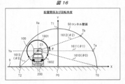
- FIG. 16 shows an arrangement relationship between the tunnel wall surface 50, the moving vehicle 200, and the displacement measuring device 100 when measuring the profile of the tunnel wall surface 50, a configuration example of the rotation angle ⁇ , and the like.
- the tunnel wall surface 50 has a semicircular arc shape in the XY cross section on the ground surface 9.
- Point P0 indicates the center point of the semicircular arc.
- Point T0 indicates the lower end of the right side wall of the tunnel corresponding to point Q0 in FIG. 15
- point T1 indicates the upper part of the tunnel corresponding to point Q1 in FIG.
- point T2 indicates the lower end of the left side wall of the tunnel.
- the moving vehicle 200 and the displacement measuring device 100 mounted thereon are arranged at the position Xa in the left lane from the center line of the road indicated by the point P0. .
- the moving vehicle 200 travels in the Z direction, which is the illustrated back direction.
- C1 indicates the position of the rotating mirror 36 that is the starting point of the measurement and irradiation of the displacement measuring apparatus 100.
- the position C1 is indicated by (Xa, Ya) as a position in the XY plane on the ground 9.
- the rotation angle ⁇ of the rotary mirror 36 at the position C1 for example, rotation of 360 ° counterclockwise on the Z axis in the XY plane is repeated at a constant angular velocity.
- the rotation start angle and position at the rotation angle ⁇ are, for example, an angle ⁇ 1 indicated by 1611 corresponding to the position Ya in the Y direction horizontal to the position C1, and a point Ta of the tunnel wall surface 50 corresponding to the angle ⁇ 1.
- the rotating mirror 36 starts irradiating light from a point Ta at an angle ⁇ 1, and rotates counterclockwise in the Z axis.
- the surface of the right side wall of the tunnel is illuminated.
- the rotating mirror 36 is irradiated on the ground surface 9 by the rotation from the angle ⁇ 3, and reaches the point T0 at the lower end of the right side wall of the tunnel corresponding to the position of the angle ⁇ 0 indicated by 1610. Subsequently, the rotation mirror 36 is irradiated from the right side wall of the tunnel by rotation from the angle ⁇ 0, and reaches the angle ⁇ 1 indicated by 1611 and the point Ta. Thereafter, similarly, the rotation of the rotation angle ⁇ of 360 ° is continued.
- the range of light irradiation by the rotation of the rotation angle ⁇ of 360 ° includes the range 1601 in which the tunnel wall surface 50 on the ground 9 is irradiated from the angle ⁇ 0 to the angle ⁇ 3.
- the displacement measurement system 300 sets at least the range 1601 on the ground 9 as a measurement target.
- the displacement measurement system 300 uses the displacement data 91, the correction value data 92, the three-dimensional profile data 93, and the difference data 94 based on the result of measuring the distance and displacement of the range 1601 from the tunnel wall surface 50.
- the rotation range of the rotation angle ⁇ has a range 1602 in which the ground 9 is irradiated from the angle ⁇ 3 to the angle ⁇ 0.
- the displacement measurement system 300 may or may not use this range 1602 as an object of measurement and data utilization.
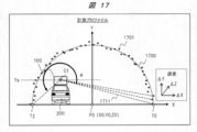
- FIG. 17 shows an example of correction value data 92 measured by the displacement measuring apparatus system 300 according to the fourth embodiment, corresponding to FIG.
- a profile 1700 shows an actual profile corresponding to the tunnel wall surface 50 in FIG. 16, that is, a semicircular arc shape on the XY plane.
- the measurement profile 1701 is a profile measured by the displacement calculation unit 80 and the correction calculation unit 120 of the displacement measurement apparatus 100 with respect to the tunnel wall surface 50 of FIG. 16, and corresponds to the correction value data 92 before performing the above-described correction.
- the measurement profile 1701 is indicated by a collection of points indicating the distance between the measurement start position C1 and the measurement target surface corresponding to each measurement time point and the rotation angle ⁇ . Note that the measurement profile 1701 in FIG. 17 is shown as a two-dimensional profile on the XY plane from which information in the Z direction is omitted.
- the measurement profile 1701 before correction has a shape including an error or noise with respect to the actual profile 1700 due to the influence of the vibration of the mobile vehicle 200, the phase comparison error of the phase comparison unit 70, and the like.
- Reference numeral 1711 denotes an example of measurement data corresponding to the point T0 as an example of distance and displacement measurement data at each measurement time point and rotation angle ⁇ in the measurement profile 1701.
- the measurement data of each point has errors ⁇ X, ⁇ Y, ⁇ Z shown in the figure due to vibrations of the mobile vehicle 200 and the like.
- the point T0 will be described as the position and time point of the measurement starting point.
- ⁇ X (t), ⁇ Y (t), ⁇ Z which are accelerations ⁇ in the X, Y, and Z directions corresponding to the measurement data at each measurement time of the measurement profile 1701 by the acceleration sensor 202 of the moving vehicle 200 described above.
- (t) is detected as a signal s32.
- t indicates each measurement time point of the measurement profile 1701, and indicates an elapsed time from the starting point T0.
- the correction calculation unit 120 uses the information of ⁇ X (t), ⁇ Y (t), ⁇ Z (t), which is the acceleration ⁇ at each measurement time of the measurement profile 1701, to calculate the vibration of the mobile vehicle 200 by the following equation.
- ⁇ X, ⁇ Y, ⁇ Z which are errors due to the above, are calculated.
- the errors ⁇ X, ⁇ Y, and ⁇ X, ⁇ Y are obtained by performing time integration twice for each of ⁇ X (t), ⁇ Y (t), and ⁇ Z (t) that are accelerations in the X, Y, and Z directions. It shows that ⁇ Z is obtained.
- the correction calculation unit 120 corrects the measurement data at each measurement point in the measurement profile 1701 using the above errors ⁇ X, ⁇ Y, and ⁇ Z. As a result, the measurement data from which the error due to the vibration of the moving vehicle 200 is removed is obtained as the correction value data 92 described above.
- the position measuring unit 201 of the moving vehicle 200 outputs the signal s31 including the information on the position or traveling distance of the moving vehicle 200 in the Z direction as described above at the time of measurement and profile calculation.
- the profile calculation unit 130 corrects the correction value data 92 that is the measurement profile 1701 using the information on the position in the Z direction or the travel distance. As a result, the profile calculation unit 130 obtains the three-dimensional profile data reflecting the information in the Z direction as the above-described three-dimensional profile data 93.
- the locus 1501 in FIG. 15 described above is an example of three-dimensional profile data.
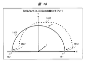
- FIG. 18 shows an example of alignment of positions in the X, Y, and Z directions of the three-dimensional profile data for the difference calculation by the difference calculation unit 140.
- Reference numerals 1801 and 1802 denote examples of three-dimensional profile data which is the three-dimensional profile data 93.
- FIG. 18 shows the shape of the portion of the XY cross section at a certain position in the Z direction among the three-dimensional profile data of X, Y, Z relating to the tunnel wall surface 50 corresponding to FIGS. 1802 indicates three-dimensional profile data obtained by the current measurement, and 1801 indicates three-dimensional profile data at a position corresponding to 1802 in the past measurement. Since the situation such as the traveling position of the mobile vehicle 200 is different for each measurement date and time, the contents of the current and past three-dimensional profile data are different in position as in the example of FIG.
- the difference calculation unit 140 first corrects the difference in the position of the three-dimensional profile data for each measurement date and time for the difference calculation of the comparison determination.
- the difference calculation unit 140 accesses the three-dimensional profile data 93 stored in the storage unit 160, and the past three-dimensional profile data corresponding to the position in the Z direction. 1801 is retrieved and read. Then, the difference calculation unit 140 compares 1801 and 1802 which are the three-dimensional profile data of the corresponding positions in the Z direction.
- the difference calculation unit 140 aligns the positions in the three-dimensional space of X, Y, and Z so that the degree of coincidence between the shapes of the three-dimensional profile data 1801 and 1802 is the highest in the comparison.
- the difference calculation unit 140 matches the point of the current three-dimensional profile data 1802 with the point of the past three-dimensional profile data 1801.
- the difference calculation unit 140 aligns the point 1812 with the point 1811 and aligns the point 1822 with the point 1821.
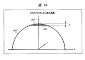
- FIG. 19 shows three-dimensional profile data after the alignment of FIG. 18 as an example of the difference calculation by the difference calculation unit 140.
- Reference numeral 1803 denotes a portion where 1801 and 1802 are overlapped so as to substantially coincide with each other.
- a horizontal line 1804 is data after alignment 1802, and indicates a portion of 1802 that does not match 1801.
- Reference numeral 1805 shown as a hatched area indicates a mismatched portion which is a difference between 1801 and 1802. Since the three-dimensional profile data 93 is three-dimensional profile data, the mismatching portion 1805 is actually a three-dimensional area.
- the difference calculation unit 140 calculates a mismatching unit 1805 that is a difference after alignment between 1801 and 1802 that is the three-dimensional profile data.
- the difference calculation unit 140 calculates the volume of the mismatching portion 1805 that is a three-dimensional region as the difference calculation.
- V be the volume of the mismatched portion 1805 which is the difference between the three-dimensional profiles.
- the volume is calculated as a difference, but the present invention is not limited to this, and a mode in which a two-dimensional area or a one-dimensional distance is calculated is also possible.
- the difference calculation unit 140 compares the volume V of the mismatched portion 1805 obtained by the difference calculation with a management value m set in advance.
- the management value m is a threshold value for comparison determination regarding the volume V that is the difference of the three-dimensional profile.
- the difference calculation unit 140 outputs a result of comparison between the volume V as a difference and the management value m to the output unit 150 as difference data 94 and stores it in the storage unit 160.
- the output unit 150 outputs a predetermined alarm to the outside or the user when the volume V of the mismatching unit 1805 is larger than the management value m as the content of the difference data 94. This alarm indicates that the distance and the displacement of the object to be measured are large.
- the output unit 150 outputs an alarm indicating that there is a danger as a sign of the collapse of the tunnel.
- the management value m can be set in advance according to the characteristics of the object to be measured.
- the displacement measuring apparatus 100 can set the management value m by a user operation in the control unit 110.
- the management value m is set in advance based on the assumption.
- the displacement measurement system 300 can perform detection and alarm output when the volume V corresponding to the displacement exceeds the management value m by the difference calculation unit 140 and the output unit 150.
- the profile of the measurement object such as the tunnel wall surface 50 can be measured with high accuracy by a simple method of performing measurement while traveling on the mobile vehicle 200. And high-frequency inspection of the object to be measured can be realized. Further, according to the fourth embodiment, high-precision measurement can be realized by the measurement data correction process using the acceleration information by the correction calculation unit 120. Further, according to the fourth embodiment, the displacement can be detected with high accuracy from the difference between the current and past profiles by the profile calculation unit 130 and the difference calculation unit 140, and an alarm can be output when the difference is large.
- a minute displacement of the tunnel wall surface 50 can be detected with high accuracy, and the accuracy of detecting a sign of tunnel collapse can be improved. As a result, serious accidents can be avoided and renovation work can be performed at an appropriate time.
- the displacement measurement system 300 equipped with the displacement measurement device 100 including the variable focus lens 37 according to the second embodiment can flexibly measure the distance between the moving vehicle 200 and the tunnel wall surface 50 that is the object to be measured. Is possible. When the distance and displacement to the tunnel wall surface 50 are measured while the moving vehicle 200 travels in one side lane in the tunnel as shown in FIG. 16, the tunnel wall surface 50 on the own lane side is close, but the tunnel wall surface 50 on the opposite lane side is far.
- the focal length of the variable focus lens 37 is adjusted according to the rotation angle ⁇ corresponding to the perspective. Thereby, the fourth embodiment stabilizes the amount of incident light on the sensor surface of the displacement measuring apparatus 100. Thereby, the measurement accuracy can be improved.
- Embodiment 4 demonstrated the example which mounted the displacement measuring device 100 of Embodiment 2, not only this but the form which mounted the displacement measuring device 100 of Embodiment 1 or Embodiment 3, etc. is also possible. Is possible.
- a configuration in which some of the components of the displacement measurement system 300 according to the fourth embodiment, for example, the output unit 150, the difference calculation unit 140, correction processing using acceleration information, and the like are omitted is also possible.
- a configuration in which the position measuring unit 201 and the acceleration sensor 202 are mounted on the displacement measuring device 100 is also possible.
- the fourth embodiment has been described by taking the tunnel measurement as an example, it can be similarly applied to other various objects to be measured such as roads, bridges, and large structures.
- the present invention can be used as a technique for measuring the distance and displacement of various objects to be measured including social infrastructure such as roads, tunnels, and bridges.
- SYMBOLS 2 Light source, 3 ... Optical system, 5, 51, 52 ... Measurement object surface, 9 ... Ground, 10 ... Intensity modulation part, 11 ... Fundamental frequency oscillator, 12 ... Low multiplication converter, 13 ... High multiplication converter, 20 DESCRIPTION OF SYMBOLS ... Optical amplifier, 21 ... Excitation laser diode, 22, 25, 26, 27 ... Optical fiber, 23 ... Multiplexer, 24 ... Dope fiber, 31 ... Collimate lens, 32 ... Beam splitter, 33 ... Condensing lens, 34 ... Measurement light detection lens, 35 ... reference light detection lens, 36 ... rotating mirror, 37, 38 ... variable focus lens, 41 ...
Landscapes
- Engineering & Computer Science (AREA)
- Physics & Mathematics (AREA)
- General Physics & Mathematics (AREA)
- Radar, Positioning & Navigation (AREA)
- Remote Sensing (AREA)
- Computer Networks & Wireless Communication (AREA)
- Electromagnetism (AREA)
- Measurement Of Optical Distance (AREA)
- Optical Radar Systems And Details Thereof (AREA)
- Length Measuring Devices By Optical Means (AREA)
Abstract
変位計測装置に関して、距離及び変位の計測の精度を向上できる技術を提供する。変位計測装置100は、周期信号を発生する強度変調部10と、周期信号に基づき光を出力する光源2と、光源2からの光を増幅する光アンプ20と、光アンプ20からの光を計測対象面5に対して照射しその反射光を入射する光学系3と、計測対象面5からの反射光を計測光として検出する計測光検出部61と、計測光の信号の位相と参照光の信号の位相とを比較する位相比較部70と、位相の比較の結果に基づいて計測対象面5までの距離及びその変位を算出する変位算出部80とを有する。
Description
本発明は、距離及び変位を計測する計測装置の技術に関する。また、本発明は、道路、トンネル、及び橋梁等の社会インフラの検査用の好適な計測装置に関する。
道路、トンネル、及び橋梁等の社会インフラの検査用に好適な計測装置として、半導体レーザ等の光源を用いて被計測物との距離及びその変位を計測する計測装置がある。
上記計測装置に関する先行技術例として、特開平3-264886号公報(特許文献1)、特開2004-347585号公報(特許文献2)が挙げられる。
特許文献1は、光学式変位センサとして、発光部からの出力光を特定の周波数で輝度変調(強度変調とも呼ばれる)し、計測物体からの反射光の位相と参照光の位相との位相差から、計測物体までの距離及び変位を計測する装置について記載されている。
特許文献2は、建築および土木構造物計測・解析システムとして、計測車に搭載し、移動距離、レーザ測距装置の方位角、俯仰角および被計測点までの距離を関連付けて記憶する、トンネル内壁面を計測するシステムについて記載されている。
また可変焦点レンズに関して、液体レンズ等の公知技術が挙げられる。液体レンズの例を記載している文献として、日本ロボット学会誌Vol.27 No.7, pp.739~748, 2009,[東大; 光学系と画像処理系の速度を整合した高速フォーカスビジョン](非特許文献1)がある。非特許文献1は、互いに混ざらない2液を開口部で接触させ、一方の液体の圧力を制御することで2液界面の曲率を変化させることにより、焦点の距離を可変とする液体レンズが記載されている。この液体レンズの応答性は1ms以下と高速である。
日本ロボット学会誌Vol.27 No.7, pp.739~748, 2009,[東大; 光学系と画像処理系の速度を整合した高速フォーカスビジョン]
従来の変位計測装置は、距離及び変位の計測の精度に関する以下のような課題がある。特許文献1のレーザ測距装置である光学式変位センサは、被計測物からの反射光を計測する。そのため、被計測物がトンネル壁面である場合のように、被計測物からの反射光が散乱する場合は、検出光量が低下する。これにより、輝度変調の波形のSNR(Signal to noise ratio)が悪くなり、被計測物の距離及び変位に関する十分な精度が得られない。一般に、上記変位の計測の精度は、SNRに比例し、SNRは、光強度の平方根に比例する。特許文献1の例を含む、一般的な方式である輝度変調によるレーザ測距装置は、変位の計測の精度として、現状、最高でも2mm程度である。
被計測物が例えばトンネル壁面である場合、その変位として5~10mm程度の変位を計測するための精度としては、0.5mm程度が必要である。即ち、上記変位の計測の精度は、変位の1/10程度が必要である。例えば5mmの変位の計測のためには、0.5mmの精度が必要である。現状のレーザ測距装置等の変位計測装置は、上記5~10mm程度の変位を計測するためには、精度的に不足する。
また、従来の変位計測装置は、変位計測装置のセンサ面と被計測物との距離の遠近に応じて測定の精度に影響するという課題がある。例えば被計測物がトンネル壁面である場合、特許文献2の例のように、レーザ測距装置等の変位計測装置を搭載した移動車により走行しながらトンネル壁面の変位を計測する方式が挙げられる。特に、移動車は、トンネル内の片側の車線を走行しながら、移動車の進行方向に対して垂直な方向へレーザによる計測光を照射し、その反射光により、トンネル壁面までの距離及びその変位を計測する方式が挙げられる。上記方式の場合、計測にあたり、変位計測装置のセンサ面から、自車線側の壁面は近いが、反対車線側の壁面は遠い。これらの両壁面からの散乱角が一定だとすると、当該センサ面と壁面との距離が遠いほど、センサ面での反射散乱光の拡がりが大きくなる。これにより、センサ面で検出される光量が減少するため、距離及び変位の計測の精度が低下する。
また、従来の変位計測装置は、変位計測装置の振動等によるノイズの影響により計測の精度が低下するという課題がある。上記の方式の場合、移動車に変位計測装置を搭載して走行しながら計測する。そのため、移動車の振動により、計測データにノイズが重畳される。そのため、このノイズが重畳された計測データのままでは、トンネル壁面などの変位量、特に小さな傷などを検出することは困難である。
本発明の目的は、変位計測装置に関して、距離及び変位の計測の精度を向上できる技術を提供することである。
本発明のうち代表的な実施の形態は、変位計測装置、及び変位計測システム、等であって、以下に示す構成を有することを特徴とする。
(1)一実施の形態の変位計測装置は、周期信号に基づき強度変調された光を出力する光源部と、前記光源部からの光を増幅して出力する光アンプと、前記光アンプからの光を被計測物に対して照射しその反射光を入射する光学系と、前記被計測物からの反射光を計測光として検出する計測光検出部と、前記計測光の信号の位相と前記光アンプからの光に基づく参照光の信号の位相とを比較する位相比較部と、前記位相の比較の結果に基づいて前記被計測物までの距離及び前記被計測物の変位を算出する変位算出部と、を有する。
(2)前記光アンプは、前記光源部からの光を増幅するための光を出力する励起部と、前記光源部からの光と前記励起部からの光とを合波する合波部と、前記合波部からの光を増幅する光導波路と、を有する。例えば、前記光アンプは、2段以上の光アンプが直列に接続されている。
(3)一実施の形態の変位計測装置において、前記光学系は、前記光アンプからの光を前記被計測物に対して集光する集光レンズと、前記被計測物を前記計測光検出部に結像する、計測光検出レンズと、を含み、前記集光レンズまたは計測光検出レンズは、可変焦点レンズにより構成され、前記可変焦点レンズの焦点距離を制御する焦点制御部を有する。
(4)前記光源部の出力する光の波長は、例えば、1000~1100nmの範囲内にある第1波長、または、1500~1650nmの範囲内にある第2波長であり、前記光アンプの前記励起部から出力する光の波長は、前記第1波長に対応させた980nm付近の第1励起波長、または、前記第2波長に対応させた前記980nm付近の第1励起波長もしくは1480nm付近の第2励起波長である。
(5)一実施の形態の変位計測システムは、被計測物までの距離及び当該被計測物の変位を計測する変位計測装置と、前記変位計測装置を搭載し、前記被計測物に対して移動する移動車と、前記移動車の位置または移動距離を計測する位置計測部と、を有する。前記変位計測装置は、周期信号に基づき強度変調された光を出力する光源部と、前記光源部からの光を増幅して出力する光アンプと、前記光アンプからの光を被計測物に対して照射しその反射光を入射する光学系と、前記光学系の後段に配置され、前記光アンプからの光を前記被計測物に対して照射しその反射光を前記光学系へ入射する回転ミラー、及び前記回転ミラーの回転角度を検出する回転角度検出部と、前記被計測物からの反射光を計測光として検出する計測光検出部と、前記計測光の信号の位相と前記光アンプからの光に基づく参照光の信号の位相とを比較する位相比較部と、前記位相の比較の結果に基づいて前記被計測物までの距離及び当該被計測物の変位を算出する変位算出部と、前記回転角度の情報、前記被計測物までの距離及び変位の情報、及び前記移動車の位置または移動距離の情報を用いて、前記被計測物の3次元のプロファイルデータを作成するプロファイル作成部と、を有する。
(6)前記変位計測システムは、前記移動車の加速度を計測する加速度計測部を有し、前記プロファイル作成部は、前記移動車の加速度の情報を用いて、前記プロファイルデータにおける回転角度ごとの前記距離及び変位のデータを補正する。
(7)前記変位計測装置は、計測日時ごとの前記被計測物の3次元のプロファイルデータを記憶する記憶部と、前記計測日時ごとのプロファイルデータを用いて、異なる計測日時のプロファイルデータの差分を演算し、当該差分と管理値とを比較し、当該比較の結果を出力する、差分演算部と、を有する。
(8)前記光学系は、前記光アンプからの光を前記被計測物に対して集光する集光レンズと、前記被計測物を前記計測光検出部に結像する、計測光検出レンズと、を含み、前記計測光検出レンズまたは集光レンズは、可変焦点レンズにより構成され、前記変位計測装置は、前記回転角度の情報を用いて前記可変焦点レンズの焦点距離を制御する焦点制御部を有する。
本発明のうち代表的な実施の形態によれば、変位計測装置に関して、距離及び変位の計測の精度を向上できる。
以下、本実施の形態を図面に基づいて詳細に説明する。なお実施の形態を説明するための全図において同一部には原則として同一符号を付しその繰り返しの説明は省略する。
<実施の形態1>
図1~図10等を用いて、実施の形態1の変位計測装置100について説明する。実施の形態1の変位計測装置100は、光源2としてレーザダイオードを用いた、強度変調の方式による、レーザ測距装置に適用した形態を示す。実施の形態1の変位計測装置100は、光アンプ20を有するレーザ測距装置である。実施の形態1の変位計測装置100は、被計測物との距離及び被計測物の変位を計測可能であり、例えば道路、トンネル、及び橋梁等の社会インフラの検査用に好適に使用可能である。
図1~図10等を用いて、実施の形態1の変位計測装置100について説明する。実施の形態1の変位計測装置100は、光源2としてレーザダイオードを用いた、強度変調の方式による、レーザ測距装置に適用した形態を示す。実施の形態1の変位計測装置100は、光アンプ20を有するレーザ測距装置である。実施の形態1の変位計測装置100は、被計測物との距離及び被計測物の変位を計測可能であり、例えば道路、トンネル、及び橋梁等の社会インフラの検査用に好適に使用可能である。
[変位計測装置]
図1は、実施の形態1の変位計測装置100を含む構成を示す。図1は、被計測物である計測対象面5を含めて図示し、また実際の距離やサイズ等は捨象して図示している。なお説明上の方向及び座標系として、図1ではX,Yを有する。X方向において、変位計測装置100と計測対象面5との距離D1、及び距離D1の差分である計測対象面5の変位d1ないしd2を計測する例を示す。
図1は、実施の形態1の変位計測装置100を含む構成を示す。図1は、被計測物である計測対象面5を含めて図示し、また実際の距離やサイズ等は捨象して図示している。なお説明上の方向及び座標系として、図1ではX,Yを有する。X方向において、変位計測装置100と計測対象面5との距離D1、及び距離D1の差分である計測対象面5の変位d1ないしd2を計測する例を示す。
変位計測装置100は、強度変調部10、光源2、光ファイバ25、光アンプ20、光ファイバ26、光学系3、位相比較部70、及び変位算出部80を有し、これらの各部がその順序で接続されている。
強度変調部10は、強度変調の方式による周期信号を発生する部分であり、基本周波数発振器11と、低逓倍変換器12と、高逓倍変換器13と、を含む。基本周波数発振器11は、基本周波数の信号s1を発振し、当該信号s1は、低逓倍変換器12及び高逓倍変換器13に送られる。低逓倍変換器12は、信号s1の周波数を低逓倍に変換した、低周波数の周期信号である信号s2を出力する。高逓倍変換器13は、信号s1の周波数を高逓倍に変換した、高周波数の周期信号である信号s3を出力する。そして信号s2と信号s3とが合成された信号s4が光源2に入力される。
光源2は、強度変調部10からの周期信号である信号s4を入力して、当該信号s4に基づく強度変調された光を光ファイバ25へ出力する。光ファイバ25は、光源2からの出力光の信号s5を伝播し、光アンプ20へ入力する。実施の形態1では、光源2は、レーザダイオードによる直接変調方式を用いる。レーザダイオードは、変調信号を入力し、変調光を出力する。なお光源2は、レーザダイオードに限らず、他の手段及び方式も適用可能である。
光アンプ20は、光源2からの出力光を光ファイバ25から入力し、光アンプ20の内部で増幅した光を光ファイバ26へ出力する。光ファイバ26は、光アンプ20からの出力光である増幅光の信号s6を伝播する。光ファイバ25及び光ファイバ26は、コア、クラッド、及び保護被膜等から構成される。
光アンプ20による増幅光の信号s6は、光ファイバ26を介して、光学系3に入射される。光学系3は、光アンプ20からの増幅光を、被計測物である計測対象面5に対して照射し、その反射光を入射する。光学系3は、コリメートレンズ31と、ビームスプリッタ32と、集光レンズ33と、計測光検出レンズ34と、参照光検出レンズ35と、計測光検出部61と、参照光検出部62と、を含む。
コリメートレンズ31は、光ファイバ26からの光a1を、平行状態に調整された光であるコリメート光a2にする。ビームスプリッタ32は、計測光と参照光とを分離する。集光レンズ33は、光学系3の出力光を計測対象面5に集光する。集光レンズ33は、コリメート光を、計測対象面5に集光する光a3にする。
計測光検出レンズ34は、コリメート光を入射して計測光検出部61の点p3に集光する。計測光検出レンズ34は、被計測物である計測対象面5の点p2を、計測光検出部61の受光部である点p3に結像する。参照光検出レンズ35は、コリメート光を入射して参照光検出部62の受光部である点p4に集光する。参照光検出レンズ35は、光ファイバ26の出射点p0を参照光検出部62の点p4に結像する。計測光検出部61は、計測対象面5からの反射光を、計測光として受光及び検出する。参照光検出部62は、光アンプ20からの光に基づく参照光を受光及び検出する。
なお変位計測装置100及び光学系3における光を出射して反射光を入射する部分を、説明上、センサ面ともいう。実施の形態1の場合、センサ面は、光学系3の集光レンズ33が相当する。なお被計測物との距離及び変位の計測及び算出にあたっては、その基準となる位置として、センサ面となる集光レンズ33の位置に限らず、補正の計算により、計測光検出部61等の位置とすることができる。
光学系3における光の流れは以下である。光アンプ20からの増幅光の信号s6は、光ファイバ26の端面の出射点p0からX方向への光a1として拡散し、コリメートレンズ31に入射される。光a1は、コリメートレンズ31により、コリメート光a2となる。コリメート光a2は、ビームスプリッタ32の点p1付近に入射される。コリメート光a2は、一部を除く成分が、ビームスプリッタ32を通過する。ビームスプリッタ32を通過したコリメート光は、集光レンズ33に入射され、集光レンズ33により集光されて出射される。集光レンズ33から出射された光a3は、X方向に存在する計測対象面5の点p2に入射する。
計測対象面5で反射された光は、再び集光レンズ33から光学系3に入射される。集光レンズ33に入射された光は、コリメート光になり、再びビームスプリッタ32の点p1付近に入射され、Y方向上側へ反射される。当該反射光は、計測光検出レンズ34で集光された後、計測光検出部61の点p3に入射され、計測光として検出される。
一方、光a1に基づくコリメート光a2の一部の成分は、ビームスプリッタ32でY方向下側へ反射されることにより分離される。当該反射光は、参照光検出レンズ35で集光された後、参照光検出部62の点p4に入射され、参照光として検出される。
位相比較部70は、計測光検出部61から出力された計測光の信号s11と、参照光検出部62から出力された参照光の信号s12とを入力する。位相比較部70は、計測光検出部61からの信号s11、及び参照光検出部62からの信号s12を周波数分離する。即ち、これらの信号は、比較のため、高周波の信号と低周波の信号とに分離される。位相比較部70は、計測光検出部61からの信号s11を周波数分離する分離部71と、参照光検出部62からの信号s12を周波数分離する分離部72と、各分離後の信号を入力して位相比較する位相比較器と、を含む。位相比較部70は、計測光の信号s11の位相と、参照光の信号s12の位相とを比較して当該比較結果の信号s13を出力する。
変位算出部80は、位相比較部70からの信号s13を入力し、この位相比較結果に基づいて、計測対象面5までの距離D1及び計測対象面5の変位d1ないしd2を算出し、当該算出結果を信号s14として出力する。
[光アンプ]
図2は、光アンプ20の構成例を示す。光アンプ20は、光ファイバ25、励起レーザダイオード21、光ファイバ22、合波器23、ドープファイバ24、及び光ファイバ26を有する。合波器23は、光ファイバ25と、励起レーザダイオード21に接続される光ファイバ22とが入力側に接続され、出力側にドープファイバ24が接続されている。ドープファイバ24の出力側に光ファイバ26が接続されている。
図2は、光アンプ20の構成例を示す。光アンプ20は、光ファイバ25、励起レーザダイオード21、光ファイバ22、合波器23、ドープファイバ24、及び光ファイバ26を有する。合波器23は、光ファイバ25と、励起レーザダイオード21に接続される光ファイバ22とが入力側に接続され、出力側にドープファイバ24が接続されている。ドープファイバ24の出力側に光ファイバ26が接続されている。
光源2であるレーザダイオードからの出射光の信号s5は、光ファイバ25を介して伝搬され、光アンプ20に入射する。光ファイバ25からの信号は、合波器23に入射する。また励起レーザダイオード21から出射する光は、光ファイバ22を介して伝搬され、合波器23に入射する。合波器23は、光源2であるレーザダイオードからの光と、励起レーザダイオード21からの光とを合波した光を、ドープファイバ24へ入射する。
ドープファイバ24は、希土類の成分がドープされた光ファイバであり、光の増幅のための光導波路を構成する。実施の形態1では、ドープファイバ24は、イッテルビウム(Yb)がドープされた光ファイバ、または、エルビウム(Er)がドープされた光ファイバを用いる。
光アンプ20は、所定の増幅率を得るために、光源2からの光をドープファイバ24に通し、増幅用の励起レーザダイオード21によって励起する。励起レーザダイオード21は、ドープファイバ24におけるドープされた元素のイオンを励起することにより、光源2であるレーザダイオードからの光を増幅する。
この結果、図2の構成の光アンプ20で得られる増幅率は、10倍程度である。また、光アンプ20を2段直列に繋ぐ構成により、20倍の増幅率を得ることができる。同様に、光アンプ20を3段以上接続する構成により、30倍以上の大きな増幅率を得る構成が可能である。
図3は、実施の形態1の変形例の変位計測装置100において、2つの光アンプ20である光アンプ20Aと光アンプ20Bとを光ファイバ27で接続した構成を示す。これにより、光源2からの光を20倍の増幅率で光学系3へ出射することができる。なお図3の構成に限らず、光源2と光学系3との間に2段以上の光アンプ20を直列に接続した構成が可能である。
[精度等の設計]
実施の形態1の変位計測装置100における、変位の計測の精度、強度変調の信号の周波数、光源2の光量、波長、及び光アンプ20の増幅率、等の設計について説明する。
実施の形態1の変位計測装置100における、変位の計測の精度、強度変調の信号の周波数、光源2の光量、波長、及び光アンプ20の増幅率、等の設計について説明する。
図4は、実施の形態1における、強度変調部10により発生する周期信号の例を示す。横軸は時間、縦軸は信号強度ないし位相を示す。上側に示す信号401は、低逓倍変換器12で発生する信号s2に対応した低周波数の低周波信号を示す。下側に示す周期信号402は、高逓倍変換器13で発生する信号s3に対応した高周波信号を示す。
本実施の形態では、周波数の設計として、低周波信号である信号401は15MHz、高周波信号である信号402は300MHzである。低周波信号である信号401と、高周波信号である信号402とは合波される。当該合波された信号s4は、光源2であるレーザダイオードに電流または電圧信号として入力される。
図5は、実施の形態1における、光源2の波長、及び光アンプ20の励起レーザダイオード21の波長の設計を示す。強度変調部10の周期信号の周波数や、光源2であるレーザダイオードの出力光の波長などは、光アンプ20の励起レーザダイオード21の出力光の波長、及びドープファイバ24による増幅の特性などに合わせて設計される。
光源2であるレーザダイオードは、連続波として、第1波長が例えば1060nm、または第2波長が1550nmである、連続波を出射する。その連続波の強度は、図4の低周波の信号401および高周波の信号402に応じて変化する。
実施の形態1の変位計測装置100は、光アンプ20により10倍~20倍の増幅率を得る。実施の形態1は、10倍の増幅率とする場合は図1の構成とし、20倍の増幅率とする場合は図3の構成とする。光アンプ20において、10倍~20倍の増幅率を得るために、ドープファイバ24として、YbドープファイバやErドープファイバを用いる。
Ybドープファイバを用いる場合、それに対応させた光源2の出力光の波長は、第1波長である1000~1100nm、例えば1060nmに設計される。Erドープファイバを用いる場合、それに対応させた光源2の出力光の波長は、第2波長である1500~1650nm、例えば1550nmに設計される。
光アンプ20において、光源2であるレーザダイオードの波長が、第1波長である1000~1100nmである場合、励起レーザダイオード21の光の波長は、第1励起波長として980nm付近(980±5nm程度)が選択される。また、光源2であるレーザダイオードの波長が、第2波長である1500~1650nmである場合、励起レーザダイオード21の光の波長は、第2励起波長として980nm付近または1480nm付近(1480±5nm程度)が選択される。
[計測光の信号及び参照光の信号]
図6は、計測光検出部61で検出した計測光の信号s11における、位相比較部70内での周波数分離後の低周波信号601及び高周波信号602を図4と同様に示す。計測日時に対応したある時間t1において、低周波信号601における信号強度ないし位相を示す点601aと、高周波信号602における信号強度ないし位相を示す点602aと、を示す。
図6は、計測光検出部61で検出した計測光の信号s11における、位相比較部70内での周波数分離後の低周波信号601及び高周波信号602を図4と同様に示す。計測日時に対応したある時間t1において、低周波信号601における信号強度ないし位相を示す点601aと、高周波信号602における信号強度ないし位相を示す点602aと、を示す。
図7は、参照光検出部62で検出した参照光の信号s12における、位相比較部70内での周波数分離後の低周波信号701及び高周波信号702を図4と同様に示す。図6と同じ計測日時に対応したある時間t1において、低周波信号701における信号強度ないし位相を示す点701aと、高周波信号702における信号強度ないし位相を示す点702aと、を示す。
[位相比較]
位相比較部70は、図6の計測光の信号と図7の参照光の信号とにおける同じ時間での位相を比較し、当該位相差を検出する。この際、位相比較部70は、低周波信号同士、及び高周波信号同士で位相を比較する。
位相比較部70は、図6の計測光の信号と図7の参照光の信号とにおける同じ時間での位相を比較し、当該位相差を検出する。この際、位相比較部70は、低周波信号同士、及び高周波信号同士で位相を比較する。
図8は、位相比較例を示す。位相比較部70は、例えば時間t1において、図6の計測光の低周波信号601の点601aと、図7の参照光の低周波信号701の点701aとの位相差を検出する。
[変位算出]
変位算出部80は、上記位相差に基づき、計測対象面5までの距離D1及び変位d1,d2を算出する。ここで、変位計測装置100のセンサ面から計測対象面5までの距離をLとし、強度変調の信号の波長をλ、波数をnとする。一般に、n=2L/λ(式1)の関係がある。また、計測の精度に相当する距離誤差をΔL、位相比較の精度に相当する位相検出誤差をΔnとする。式1、距離誤差ΔL、及び位相検出誤差Δnから、必要な波長λは、λ=2ΔL/Δn(式2)で決まる。
変位算出部80は、上記位相差に基づき、計測対象面5までの距離D1及び変位d1,d2を算出する。ここで、変位計測装置100のセンサ面から計測対象面5までの距離をLとし、強度変調の信号の波長をλ、波数をnとする。一般に、n=2L/λ(式1)の関係がある。また、計測の精度に相当する距離誤差をΔL、位相比較の精度に相当する位相検出誤差をΔnとする。式1、距離誤差ΔL、及び位相検出誤差Δnから、必要な波長λは、λ=2ΔL/Δn(式2)で決まる。
位相比較部70の位相比較の精度は、一般的に1/1000程度である。即ちΔn=1/1000とする。実施の形態1の変位計測装置100において計測に必要な精度を、例えばトンネル壁面の変位の計測に必要な精度に合わせて、0.5mmとする。即ちΔL=0.5mmとする。0.5mmの精度を得るための波長λは、式2から、λ=2×0.5mm/(1/1000)=1000mm=1mとなる。波長λを周波数fに換算するには、光速cとしてc=3×108m/sを用いると、f=c/λ(式3)である。式3から、f=300MHzとなる。この周波数f=300MHzを、前述の強度変調部10の高周波の信号s3の周波数とする。
一方、計測対象面5までの距離Lを、例えばトンネル壁面の計測時の距離を想定して、最大20mとする。すると、強度変調の信号の波長λは、λ=20mとなる。この波長λに対応する周波数fは、式3から、f=15MHzとなる。この周波数f=15MHzを、前述の強度変調部10の低周波の信号s2の周波数とする。
[計測光のノイズ]
図9は、従来例の変位計測装置における、計測対象面の反射光が少ない場合の計測光の信号901を示す。この計測光の信号901は、図示するようにショットノイズが大きく重畳されている。そのため、従来例の変位計測装置は、この計測光の信号901を用いた場合、高精度の位相検出は困難である。
図9は、従来例の変位計測装置における、計測対象面の反射光が少ない場合の計測光の信号901を示す。この計測光の信号901は、図示するようにショットノイズが大きく重畳されている。そのため、従来例の変位計測装置は、この計測光の信号901を用いた場合、高精度の位相検出は困難である。
一方、図10は、実施の形態1の変位計測装置100における、特に図3の2段の光アンプ20の構成による、増幅率が20倍の場合の、計測光検出部61による計測光の信号1001を示す。この計測光の信号1001は、図示するように、図9の計測光の信号901に比べて、ノイズが減っている。即ち、実施の形態1によれば、位相検出の精度が向上することが分かる。
[効果等]
以上のように、実施の形態1及びその変形例によれば、光アンプ20を導入する構成により、高精度なレーザ距離計測が実現できる。対象物の高頻度の検査及び高精度の計測のためには、変位計測の方式として、上述のレーザダイオード等の光源を用いた、強度変調及び位相比較による方式が有効な候補となる。従来のこの方式の変位計測装置は、例えばトンネル壁面等の変位計測のために必要な精度である0.5mmの精度は得られなかった。一方、実施の形態1によれば、光アンプ20による光量の増加の結果、検出される強度変調の信号の波形のSNRが向上し、例えば従来の4倍の精度である0.5mmの精度が達成できる。
以上のように、実施の形態1及びその変形例によれば、光アンプ20を導入する構成により、高精度なレーザ距離計測が実現できる。対象物の高頻度の検査及び高精度の計測のためには、変位計測の方式として、上述のレーザダイオード等の光源を用いた、強度変調及び位相比較による方式が有効な候補となる。従来のこの方式の変位計測装置は、例えばトンネル壁面等の変位計測のために必要な精度である0.5mmの精度は得られなかった。一方、実施の形態1によれば、光アンプ20による光量の増加の結果、検出される強度変調の信号の波形のSNRが向上し、例えば従来の4倍の精度である0.5mmの精度が達成できる。
なお実施の形態1では、強度変調部10からの低周波信号401(s2)及び高周波信号402(s3)を光源2であるレーザダイオードに加えることにより、光源2の出射光を強度変調させた。強度変調の方式は、上記に限らず可能である。例えば、光源2であるレーザダイオードの出射光を、公知技術である音響光学変調器(Acoust Optical Modulators)や電気光学変調器(Electro-Optic Modulators)に入射させ、これらの変調器に低周波信号401及び高周波信号402を加えることにより強度変調させてもよい。即ち、実施の形態1の変形例として、光源2と光アンプ20との間に上記変調器を含む強度変調部を設ける形態が可能である。
<実施の形態2>
図11を用いて、実施の形態2の変位計測装置について説明する。実施の形態2の変位計測装置は、可変焦点レンズを導入したレーザ距離計測装置を示す。特に実施の形態2では、前述の図1の計測光検出レンズ34の箇所を、可変焦点レンズ37で置き換えた構成を有する。
図11を用いて、実施の形態2の変位計測装置について説明する。実施の形態2の変位計測装置は、可変焦点レンズを導入したレーザ距離計測装置を示す。特に実施の形態2では、前述の図1の計測光検出レンズ34の箇所を、可変焦点レンズ37で置き換えた構成を有する。
図11は、実施の形態2の変位計測装置100を含む構成を示す。実施の形態2の変位計測装置100は、実施の形態1に対して異なる要素として、光学系3内の可変焦点レンズ37、焦点制御部170、焦点制御量記憶部171等を有する。
実施の形態2では、被計測物である計測対象面5までの距離の変化に柔軟に対応できるようにするために、変位計測装置100のセンサ面と計測対象面5とを結像関係におくと共に、光学系3の構成要素として、可変焦点レンズ37を用いる。可変焦点レンズ37は、計測対象面5からの反射光を、計測光検出部61の点p3に結像する。
可変焦点レンズ37は、焦点制御部170からの制御に基づき、焦点の距離を高速に可変できるレンズである。可変焦点レンズ37として、例えば液体レンズを用いる。液体レンズの詳細については前述の非特許文献1等に記載されている。
変位計測装置100は、例えば被計測物の移動あるいは変位計測装置100自体の移動による、計測対象面5までの距離D1の変化に対応させて、上記可変焦点レンズ37の焦点距離を可変させる。
図11では、X方向における計測対象面5の位置の変動を、距離D2,D3で示している。なおこの距離D2,D3は図1の変位d1,d2とは異なる。図1と同様の計測対象面5までの距離D1を基準とする。計測対象面51は、基準の距離D1の位置から、X方向の手前側に距離D2の分近い位置に移動した場合を示す。同様に、計測対象面52は、基準の距離D1の位置から、X方向の奥側に距離D3の分遠い位置に移動した場合を示す。例えば、計測対象面5がトンネル壁面である場合、トンネル内での変位計測装置100の位置に応じて、トンネル壁面までの距離は変化する。
焦点制御部170は、可変焦点レンズ37、計測光検出部61、及び焦点制御量記憶部171に接続される。焦点制御部170は、可変焦点レンズ37に電圧または電流による信号を印加する。これにより可変焦点レンズ37の焦点距離が制御される。a51は、計測対象面51の点p2aに焦点が結像されたときの光を示す。a52は、計測対象面52の点p2bに焦点が結像されたときの光を示す。
焦点制御量記憶部171は、上記焦点制御のための制御量を記憶する。この制御量は、例えば、変位計測装置100のセンサ面と計測対象面5との距離と、上記焦点制御のための制御量としての電圧または電流値との対応関係の情報を含む。
なお上記焦点制御量は、予め変位計測装置100の焦点制御量記憶部171に設定されていてもよいし、焦点制御部170及び焦点制御量記憶部171に対するユーザによる設定を可能としてもよい。またユーザの必要に応じてユーザの手動操作により焦点制御部170を通じて可変焦点レンズ37の焦点距離を調整できる。
変位計測装置100は、計測対象面5の位置が図11の例のように変動する場合、それに対応させて、焦点制御部170により可変焦点レンズ37の焦点距離を変更させる。この可変焦点レンズ37の焦点距離により、計測光検出部61の点p3に計測対象面が結像されるようにする。こうして可変焦点レンズ37の焦点距離を制御することにより、計測光検出部61において常に十分な反射光による計測光を受光することができる。これにより当該計測光を用いた距離及び変位の計測の精度を高くできる。
上記のように、実施の形態2によれば、可変焦点レンズ37を含む構成により、計測の状況として、変位計測装置100のセンサ面と計測対象面5との距離がある程度変化する場合にも、前述の反射散乱光等によるセンサ面の検出光量の変動を低減できる。よって、実施の形態2によれば、上記のように距離がある程度変化する場合にも、柔軟に対応でき、計測の精度を安定に保つことができる。
<実施の形態3>
図12を用いて、実施の形態3の変位計測装置について説明する。実施の形態3の変位計測装置は、実施の形態2と同様に、可変焦点レンズを導入したレーザ距離計測装置を示す。特に実施の形態3では、前述の図1の集光レンズ33の箇所を、可変焦点レンズ38で置き換えた構成を有する。
図12を用いて、実施の形態3の変位計測装置について説明する。実施の形態3の変位計測装置は、実施の形態2と同様に、可変焦点レンズを導入したレーザ距離計測装置を示す。特に実施の形態3では、前述の図1の集光レンズ33の箇所を、可変焦点レンズ38で置き換えた構成を有する。
図12は、実施の形態3の変位計測装置100を含む構成を示す。実施の形態3の変位計測装置100は、実施の形態1に対して異なる要素として、光学系3内の可変焦点レンズ38、焦点制御部170、焦点制御量記憶部171等を有する。
実施の形態3の変位計測装置100は、集光レンズ33を可変焦点レンズ38にした構成により、計測対象面5からの反射光を計測光検出部61の点p3に結像するだけでなく、計測対象面5への照射光についても、計測対象面5の位置の変化に応じて集光させることができる。よって、実施の形態3は、計測光検出部61における計測光の検出量を更に増加させることができる。従って、実施の形態3は、レーザ距離計測の精度を更に向上させることができる。
<実施の形態4>
図13~図19等を用いて、実施の形態4の変位計測システム300について説明する。実施の形態4の変位計測システム300は、移動車200に変位計測装置100であるレーザ測距装置を搭載することにより構成される、プロファイル計測システムの構成を示す。実施の形態4の変位計測システム300を構成する変位計測装置100は、前述の実施の形態2の変位計測装置100のすべての構成要素及び機能と、実施の形態4に特有の構成要素及び機能とを備える。即ち、実施の形態4は、前述の光アンプ20、可変焦点レンズ37、及び変位算出部80などを備えている。
図13~図19等を用いて、実施の形態4の変位計測システム300について説明する。実施の形態4の変位計測システム300は、移動車200に変位計測装置100であるレーザ測距装置を搭載することにより構成される、プロファイル計測システムの構成を示す。実施の形態4の変位計測システム300を構成する変位計測装置100は、前述の実施の形態2の変位計測装置100のすべての構成要素及び機能と、実施の形態4に特有の構成要素及び機能とを備える。即ち、実施の形態4は、前述の光アンプ20、可変焦点レンズ37、及び変位算出部80などを備えている。
また実施の形態4は、被計測物である計測対象面5の例としてトンネル壁面50とし、移動車200により走行しながらこのトンネル壁面50の変位を計測する例を説明する。実施の形態4の変位計測システム300は、プロファイル計測システムとして、トンネル壁面50のプロファイルを計測する機能を有する。このプロファイルは、3次元空間内での距離及び変位の計測によるトンネル壁面50の形状を示すプロファイルである。また、このプロファイルは、計測日時に応じた時間軸上のトンネル壁面50の形状の変化を含むプロファイルである。
[変位計測システム]
図13は、実施の形態4の変位計測システム300の概要構成を示す。実施の形態4の変位計測システム300は、移動車200と、移動車200に搭載される変位計測装置100とを有する。移動車200は、位置計測部201、加速度センサ202を有する。移動車200は地面9上を例えばZ方向に走行する。図13は、被計測物である計測対象面としてトンネル壁面50を有し、移動車200及び変位計測装置100のY方向上側に図示している。なお説明上の方向及び座標系として、X,Y,Zを示す。移動車200の進行方向をZ方向とし、Z方向に対して垂直な面を構成する方向をX方向及びY方向とする。X方向は地面9に対して水平方向、Y方向は地面9に対して垂直方向とする。
図13は、実施の形態4の変位計測システム300の概要構成を示す。実施の形態4の変位計測システム300は、移動車200と、移動車200に搭載される変位計測装置100とを有する。移動車200は、位置計測部201、加速度センサ202を有する。移動車200は地面9上を例えばZ方向に走行する。図13は、被計測物である計測対象面としてトンネル壁面50を有し、移動車200及び変位計測装置100のY方向上側に図示している。なお説明上の方向及び座標系として、X,Y,Zを示す。移動車200の進行方向をZ方向とし、Z方向に対して垂直な面を構成する方向をX方向及びY方向とする。X方向は地面9に対して水平方向、Y方向は地面9に対して垂直方向とする。
移動車200は、被計測物であるトンネル壁面50に対してZ方向で移動する。移動車200は、例えば車体上面に変位計測装置100を搭載する。位置計測部201は、移動車200の位置または走行距離を計測する部分であり、例えば移動車200の車輪の回転数をもとに走行距離を算出する走行距離センサ等である。位置計測部201は、少なくとも、移動車200のZ方向の位置または走行距離を計測する。位置計測部201で計測した位置または走行距離の情報は、信号s31として、プロファイル算出部130に送られる。加速度センサ202は、移動車200の加速度(αとする)を、時間軸及びX,Y,Zの3次元空間内の加速度αとして計測する。加速度センサ202で計測した加速度αの情報は、信号s32として、補正演算部120に送られる。
変位計測装置100は、前述の実施の形態2と同様の要素に加え、回転ミラー36、駆動系41、ロータリエンコーダ42、制御部110、補正演算部120、プロファイル算出部130、差分演算部140、出力部150、及び記憶部160等を有する。
回転ミラー36は、光学系3と計測対象面であるトンネル壁面50との間の位置、特に光学系3の集光レンズ33の後段であるZ方向前方の位置に配置されている。回転ミラー36は、光学系3の集光レンズ33から出射された光a3を点p6付近に入射し、YZ平面における点p6を含む45度のミラーの面において、Y方向へ反射する。図13の状態では、回転ミラー36に入射された光a3は、Y方向上側へ反射され、当該反射された光a6は、トンネル壁面50の点p7に照射される。トンネル壁面50の点p7で反射された光は、再び回転ミラー36で反射され、Z方向の光となり、光学系3の集光レンズ33に入射される。
駆動系41は、回転ミラー36をZ軸の周りに回転させる駆動を行う。この回転の角度をθとする。この回転は、360°の回転を一定の角速度で継続する。回転ミラー36の360°の回転により、計測対象面であるトンネル壁面50への集光光である光a6は、XY平面内で360度回転される。回転ミラー36の回転により、トンネル壁面50に光が照射される点の軌跡は、XY平面内での軌跡となる。更に移動車200のZ方向への移動により、上記被計測物への照射光の点の軌跡は、X,Y,Zの3次元空間内の軌跡となる。なお上記の回転は、回転ミラー36及び駆動系41の構成に応じて、Z方向に垂直なXY平面内での角度θの回転に限らずに同様に可能である。
駆動系41は、ロータリエンコーダ42が設置されている。ロータリエンコーダ42は、回転角度検出部であり、回転ミラー36の回転角度θを計測及び検出し、その回転角度θの信号s41及び信号s42を出力する。一方の信号s41は、前述の焦点制御部170に入力される。他方の信号s42は、補正演算部120に入力される。
焦点制御部170は、信号s41の回転角度θの情報、及び焦点制御量記憶部171の情報を用いて、光学系3内の可変焦点レンズ37の焦点距離を前述のように制御する。焦点制御部170は、焦点制御量記憶部171から読み出す情報における、その時の回転角度θの状態に関係付けられた焦点制御量を用いて、焦点可変レンズ37の焦点距離を制御する。実施の形態4の場合、焦点制御量として、回転ミラー36の回転角度θと焦点制御量との対応関係の情報を用いることができる。これにより、回転ミラー36の回転角度θの状態に応じて自動的に可変焦点レンズ37の焦点距離が制御され、計測対象面であるトンネル壁面50に焦点が追随できる。
[変位計測装置]
図14は、図13の実施の形態4の変位計測システム300に備える変位計測装置100の内部の構成を主に示す。まず前述の変位算出部80は、変位計測装置100と計測対象面であるトンネル壁面50との距離及びその変位を算出し、その結果の信号s14を補正演算部120に出力する。また、変位算出部80で得られた距離及び変位の情報は、変位データ91として、記憶部160内に保存される。
図14は、図13の実施の形態4の変位計測システム300に備える変位計測装置100の内部の構成を主に示す。まず前述の変位算出部80は、変位計測装置100と計測対象面であるトンネル壁面50との距離及びその変位を算出し、その結果の信号s14を補正演算部120に出力する。また、変位算出部80で得られた距離及び変位の情報は、変位データ91として、記憶部160内に保存される。
制御部110は、変位計測システム300の全体を制御する部分であり、例えば公知のCPU、RAM、ROM、入力デバイス、出力デバイス、通信インタフェース、バス、及び電源部、等を含む構成を有する。また、制御部110は、ユーザの操作による設定入力を受け付ける。例えば、制御部110は、ユーザの操作に基づき、記憶部160に保存されている各データを出力する機能を有する。
記憶部160は、変位データ91、補正値データ92、3次元プロファイルデータ93、差分データ94、等の各データを記憶する。またこれらの各データは、異なる計測日時に対応した、時間軸上の計測日時ごとのデータである時系列データとして整理されて保存される。
補正演算部120及びプロファイル算出部130は、回転角度θの情報、被計測物までの距離及び変位の情報、及び移動車200の位置または移動距離の情報を用いて、被計測物の3次元のプロファイルデータを作成する。
補正演算部120は、変位算出部80による距離及び変位の情報を含む信号s14または記憶部160の変位データ91を入力する。ここでは補正演算部120は、変位データ91を用いて処理を行うとする。補正演算部120は、変位データ91と、信号s42による回転角度θの情報と、信号s32による加速度αの情報とを用いて、被計測物であるトンネル壁面50に関する計測データの補正値を算出する。補正演算部120は、この結果である補正後の計測データの情報を含む信号s21を、プロファイル算出部130へ出力する。また、補正演算部120は、この結果である補正値データ92を、記憶部160に保存する。補正値データ92は、回転角度θの情報と、その回転角度θのときの被計測物であるトンネル壁面50までの距離及び変位の情報とを含む。
補正演算部120は、特に、移動車200の加速度αの情報を用いて、各計測時点のトンネル壁面50との距離及び変位のデータを補正する。これにより、移動車200の走行時の振動によるノイズないし誤差の影響を低減する。この結果、得られる補正値データ92は、各計測時点の変位のずれが少ないデータとなる。この補正の例については後述する。なお上記加速度αの情報を用いた距離及び変位の計測データの補正の処理を、プロファイル算出部130でまとめて行うようにしてもよい。
プロファイル算出部130は、位置計測部201からの移動車200の位置の情報を含む信号s31を用いて、補正演算部120による上記補正後の計測データの情報を含む信号s21、または記憶部160の補正値データ92を補正する処理を行う。ここでは補正値データ92を用いて処理を行うとする。補正値データ92は、XY平面内の回転角度θと被計測物までの距離及び変位の情報は含まれているが、Z方向の位置の情報は反映されていない。プロファイル算出部130は、補正値データ92にZ方向の位置の情報を反映するように補正する処理を行う。プロファイル算出部130は、この補正の結果を、3次元プロファイルの情報を含む信号s22として、差分演算部140へ出力する。また、プロファイル算出部130は、この補正の結果を、3次元プロファイルデータ93として、記憶部160に保存する。上記補正後のデータは、X,Y,Zの3次元空間内での被計測物の照射光の点の軌跡を示す3次元プロファイルデータとなる。
差分演算部140は、プロファイル算出部130からの3次元プロファイルの情報を含む信号s22、または記憶部160に記憶されている各計測日時の3次元プロファイルデータ93等を読み出し、差分演算による比較判定処理を行う。差分演算部140は、時間軸上の異なる計測日時の3次元プロファイルデータ93における、同じ3次元空間の位置に関する差分を算出する。差分演算部140は、例えば、現在の計測時点の3次元プロファイルデータ93のうちのある位置での距離及び変位のデータと、過去の3次元プロファイルデータ93のうちの同じ位置での距離及び変位のデータとを比較し、差分を算出する。
差分演算部140は、上記差分を、所定の管理値と比較する。これにより、差分演算部140は、3次元空間内の同じ位置における計測データの変動を判定する。差分演算部140は、差分と管理値との比較の結果を含む信号s23を出力部150へ出力する。また、差分演算部140は、差分と管理値との比較の結果を差分データ94として記憶部160に保存する。
出力部150は、上記差分演算部140による信号s23または差分データ94を用いて、上記差分が管理値以上である場合、当該情報またはアラームを外部及びユーザに対して出力する。管理値は、例えば予め変位計測装置100の差分演算部140等に設定されている。あるいは、制御部110に対するユーザの設定操作により、被計測物などに応じて管理値が設定可能となっている。
なお実施の形態4の各部の構成は、上記構成に限らず、補正演算部120とプロファイル算出部130とを1つに統合した構成や、差分演算部140と出力部150とを1つに統合した構成なども可能である。
[トンネル壁面]
図15は、X,Y,Zの3次元空間における被計測物及び計測対象面であるトンネル壁面50の形状、及びトンネル壁面50への照射光の軌跡などの例を示す。このトンネル壁面50のXY断面の形状は、半円弧形状である。X,Y,Zの3次元空間における、XY平面での回転ミラー36の回転角度θの360°の回転、及び移動車200のZ方向への移動による、トンネル壁面50への照射光の軌跡は、Z方向への螺旋形状となる。
図15は、X,Y,Zの3次元空間における被計測物及び計測対象面であるトンネル壁面50の形状、及びトンネル壁面50への照射光の軌跡などの例を示す。このトンネル壁面50のXY断面の形状は、半円弧形状である。X,Y,Zの3次元空間における、XY平面での回転ミラー36の回転角度θの360°の回転、及び移動車200のZ方向への移動による、トンネル壁面50への照射光の軌跡は、Z方向への螺旋形状となる。
図15の例では、上記回転に基づく計測の際、まずトンネル右側壁の下端の点Q0から光の照射が開始される。1501は、トンネルの半円弧形状の照射光の軌跡、及び当該軌跡に対応した3次元プロファイルを示す。軌跡1501において、点Q0から、トンネル上部の点Q1を経て、図示しないトンネル左側壁の下端の点まで光の照射がされる。これにより、軌跡1501に対応した3次元プロファイルが3次元プロファイルデータ93として得られる。この3次元プロファイルは、計測時点に対応した回転角度θの情報と、その計測時点の回転角度θに対応したトンネル壁面50までの距離及び変位の情報と、それに関係付けられた移動車200のZ方向の位置の情報とを有する。
続いて、トンネル左側壁の下端の点から回転角度θの回転が継続し、図15では省略しているが地面9の部分についても光の照射及び計測がされる。そして光の照射は、Z方向に1単位分進んだ、トンネル右側壁の下端の点Q3へ至る。続いて、トンネル右側壁の下端の点Q3から、同様に軌跡1502で示す光の照射がされ、対応する3次元プロファイルが得られる。以後同様に、軌跡1503のように、Z方向へ繰り返して計測がされる。
[配置関係及び回転角度]
図16は、上記トンネル壁面50のプロファイルを計測する際の、トンネル壁面50と移動車200及び変位計測装置100との配置の関係や、回転角度θの構成例などを示す。トンネル壁面50は、地面9上におけるXY断面において半円弧形状である。点P0は半円弧の中心点を示す。点T0は、図15の点Q0と対応するトンネル右側壁の下端を示し、点T1は、図15の点Q1と対応するトンネル上部を示し、点T2は、トンネル左側壁の下端を示す。
図16は、上記トンネル壁面50のプロファイルを計測する際の、トンネル壁面50と移動車200及び変位計測装置100との配置の関係や、回転角度θの構成例などを示す。トンネル壁面50は、地面9上におけるXY断面において半円弧形状である。点P0は半円弧の中心点を示す。点T0は、図15の点Q0と対応するトンネル右側壁の下端を示し、点T1は、図15の点Q1と対応するトンネル上部を示し、点T2は、トンネル左側壁の下端を示す。
図16では、トンネル内部における移動車200の位置として、点P0で示す道路の中央線から左側の車線内のXaの位置に、移動車200及びそれに搭載された変位計測装置100が配置されている。移動車200は、図示の奥方向であるZ方向へ走行する。C1は、変位計測装置100の計測及び照射の起点である回転ミラー36の位置を示す。位置C1は、地面9上のXY平面内の位置として、(Xa,Ya)で示される。
位置C1における回転ミラー36の回転角度θは、例えばXY平面においてZ軸左回りに360°の回転を一定の角速度で繰り返す。回転角度θにおける回転の開始の角度及び位置を、例えば位置C1に水平なY方向の位置Yaに対応した、1611で示す角度θ1、及び角度θ1に対応したトンネル壁面50の点Taとする。回転ミラー36は、角度θ1の点Taから光の照射を開始し、Z軸左回りに回転する。トンネル右側壁の面が照射される。例えば1612で示す角度θ2の位置では、トンネル右側壁の点Tbに光が照射されている。更に、回転ミラー36は、回転を続け、トンネル上部の点T1を経由し、トンネル左側壁の面が照射され、1613で示す角度θ3の位置に対応したトンネル左側壁の下端の点T2まで照射される。
続いて、回転ミラー36は、角度θ3からの回転により、地面9上が照射され、1610で示す角度θ0の位置に対応するトンネル右側壁の下端の点T0へ至る。続いて、回転ミラー36は、角度θ0からの回転により、トンネル右側壁が照射され、上記1611で示す角度θ1、及び点Taへ至る。以後同様に、回転角度θの360°の回転が継続される。
上記のように、回転角度θの360°の回転による光の照射の範囲は、角度θ0から角度θ3までの、地面9上のトンネル壁面50が照射される範囲1601を含む。実施の形態4の変位計測システム300は、上記の地面9上の範囲1601を、少なくとも、計測の対象とする。変位計測システム300は、当該範囲1601のトンネル壁面50との距離及び変位を計測した結果による、変位データ91、補正値データ92、3次元プロファイルデータ93、及び差分データ94を活用する。
また、回転角度θの回転の範囲は、角度θ3から角度θ0までの、地面9が照射される範囲1602を有する。変位計測システム300は、この範囲1602を、計測及びデータ活用の対象としてもよいし、しなくてもよい。
[プロファイル]
図17は、図16に対応した、実施の形態4の変位計測装置システム300により計測された補正値データ92の例を示す。まずプロファイル1700は、図16のトンネル壁面50に対応した実際のプロファイル、即ちXY平面での半円弧の形状を示す。計測プロファイル1701は、図16のトンネル壁面50を対象として変位計測装置100の変位算出部80及び補正演算部120により計測したプロファイルであり、前述の補正を行う前の補正値データ92に相当する。
図17は、図16に対応した、実施の形態4の変位計測装置システム300により計測された補正値データ92の例を示す。まずプロファイル1700は、図16のトンネル壁面50に対応した実際のプロファイル、即ちXY平面での半円弧の形状を示す。計測プロファイル1701は、図16のトンネル壁面50を対象として変位計測装置100の変位算出部80及び補正演算部120により計測したプロファイルであり、前述の補正を行う前の補正値データ92に相当する。
計測プロファイル1701は、各計測時点及び回転角度θに対応した、計測起点の位置C1と計測対象面との距離を示す点の集まりで示される。なお図17の計測プロファイル1701は、Z方向の情報は省略したXY平面での2次元のプロファイルとして示している。またこの補正前の計測プロファイル1701は、移動車200の振動や位相比較部70の位相比較誤差などの影響によって、実際のプロファイル1700に対して誤差ないしノイズを含んだ形状となっている。
そこで、前述のように、補正演算部120により変位データ91を用いて補正値データ92を算出する際に、移動車200の加速度αの情報を用いて、計測プロファイル1701の個々の計測時点のデータを補正する処理を行う。1711は、計測プロファイル1701における個々の計測時点及び回転角度θにおける距離及び変位の計測データの例として、点T0に対応した計測データの例を示す。これらの各点の計測データは、移動車200の振動等に起因する図示する誤差ΔX,ΔY,ΔZを有する。なお以下の説明では、点T0を、計測の起点の位置及び時点として説明する。
前述の移動車200の加速度センサ202により、計測プロファイル1701の各計測時点の計測データに対応した、X,Y,Zの各方向の加速度αである、αX(t),αY(t),αZ(t)を信号s32として検出する。tは、計測プロファイル1701の各計測時点を示し、起点の点T0からの経過時間を示す。
補正演算部120は、上記計測プロファイル1701の各計測時点の加速度αであるαX(t),αY(t),αZ(t)の情報を用いて、下記の式により、移動車200の振動等に起因する誤差であるΔX,ΔY,ΔZを算出する。なお下記の式では、X,Y,Zの各方向の加速度であるαX(t),αY(t),αZ(t)ごとに、時間の積分を2回行うことにより、誤差ΔX,ΔY,ΔZが得られることを示している。

そして、補正演算部120は、上記の誤差ΔX,ΔY,ΔZを用いて、計測プロファイル1701の各計測時点の計測データを補正する。これにより、移動車200の振動等の影響による誤差が取り除かれた計測データが、前述の補正値データ92として得られる。
[3次元プロファイル]
移動車200の位置計測部201は、上記計測及びプロファイルの算出時に、前述のように移動車200のZ方向の位置または走行距離の情報を含む信号s31を出力する。プロファイル算出部130は、上記Z方向の位置または走行距離の情報を用いて、上記計測プロファイル1701である補正値データ92を補正処理する。これにより、プロファイル算出部130は、Z方向の情報を反映した3次元プロファイルデータを前述の3次元プロファイルデータ93として得る。前述の図15の軌跡1501等は、3次元プロファイルデータの例である。
移動車200の位置計測部201は、上記計測及びプロファイルの算出時に、前述のように移動車200のZ方向の位置または走行距離の情報を含む信号s31を出力する。プロファイル算出部130は、上記Z方向の位置または走行距離の情報を用いて、上記計測プロファイル1701である補正値データ92を補正処理する。これにより、プロファイル算出部130は、Z方向の情報を反映した3次元プロファイルデータを前述の3次元プロファイルデータ93として得る。前述の図15の軌跡1501等は、3次元プロファイルデータの例である。
[差分演算]
図18は、差分演算部140による差分演算のための、3次元プロファイルデータのX,Y,Z方向の位置のアライメントの例を示す。1801,1802は、3次元プロファイルデータ93である3次元プロファイルデータの例を示す。なお図18は、図15~図17に対応したトンネル壁面50に関するX,Y,Zの3次元プロファイルデータのうち、あるZ方向の位置におけるXY断面の部分の形状を示す。1802は、現在の計測により得られた3次元プロファイルデータを示し、1801は、過去の計測における1802と対応する位置の3次元プロファイルデータを示す。計測日時ごとに、移動車200の走行位置などの状況が異なるので、現在と過去の3次元プロファイルデータの内容は、図18の例のように、位置の違いがある。
図18は、差分演算部140による差分演算のための、3次元プロファイルデータのX,Y,Z方向の位置のアライメントの例を示す。1801,1802は、3次元プロファイルデータ93である3次元プロファイルデータの例を示す。なお図18は、図15~図17に対応したトンネル壁面50に関するX,Y,Zの3次元プロファイルデータのうち、あるZ方向の位置におけるXY断面の部分の形状を示す。1802は、現在の計測により得られた3次元プロファイルデータを示し、1801は、過去の計測における1802と対応する位置の3次元プロファイルデータを示す。計測日時ごとに、移動車200の走行位置などの状況が異なるので、現在と過去の3次元プロファイルデータの内容は、図18の例のように、位置の違いがある。
差分演算部140は、比較判定の差分演算のために、まず上記計測日時ごとの3次元プロファイルデータの位置の違いを補正する。差分演算部140は、現在の3次元プロファイルデータ1802を差分演算する際、記憶部160に記憶されている3次元プロファイルデータ93にアクセスし、Z方向の位置が対応する、過去の3次元プロファイルデータ1801を検索して読み出す。そして、差分演算部140は、対応するZ方向の位置の3次元プロファイルデータである1801と1802とを比較する。
差分演算部140は、上記比較において、3次元プロファイルデータである1801と1802との形状の一致度が最も高くなるように、X,Y,Zの3次元空間での位置をアライメントする。図18では、差分演算部140は、過去の3次元プロファイルデータ1801の点に対し、現在の3次元プロファイルデータ1802の点を合わせる。差分演算部140は、例えば、点1811に点1812を合わせ、点1821に点1822を合わせる。
図19は、差分演算部140による差分演算の例として、図18のアライメントの後の3次元プロファイルデータを示す。1803は、1801と1802とがほぼ一致するように重ね合わされた部分を示す。1804の横線は、1802のアライメント後のデータであり、1802のうち1801とは一致しない部分を示す。斜線の領域として示す1805は、1801と1802との差分である不一致部を示す。なお3次元プロファイルデータ93は3次元プロファイルデータであるため、不一致部1805は実際には3次元の領域である。
差分演算部140は、上記3次元プロファイルデータである1801と1802とのアライメント後の差分である不一致部1805を算出する。差分演算部140は、差分演算として、3次元の領域である不一致部1805の体積を演算する。この3次元プロファイルの差分である不一致部1805の体積をVとする。なお本実施の形態では差分として体積を算出するが、これに限らず、2次元の面積や1次元の距離を算出する形態も同様に可能である。
差分演算部140は、上記差分演算により得た不一致部1805の体積Vと、予め設定された管理値mとを比較する。管理値mは、当該3次元プロファイルの差分である体積Vに関する比較判定用の閾値である。差分演算部140は、差分である体積Vと管理値mとの比較の結果を差分データ94として出力部150に出力し、記憶部160に保存する。
出力部150は、上記差分データ94の内容として、不一致部1805の体積Vが管理値mよりも大きい場合、所定のアラームを外部またはユーザに対して出力する。このアラームは、被計測物における距離及び変位の変動が大きいことを示す。被計測物がトンネル壁面50である場合、出力部150は、トンネル崩落の予兆として危険性有りを示すアラームを出力する。
なお上記管理値mは、被計測物の特性などに応じて予め設定可能である。例えば、変位計測装置100は、制御部110においてユーザの操作により管理値mを設定可能である。例えば、トンネル壁面50のY方向上側の面において、土砂の圧力などがかかることにより、図19の例のように、不一致部1805で示す変位が発生すると考えられる。そこで、当該想定に基づき、上記管理値mが予め設定される。
例えばトンネル崩落前の変位はトンネル施工時の変位と同等程度存在する、と仮定し、当該仮定における変位を例えば5~10mmとする。これに対応させて、上記管理値mとして、当該5~10mmに対応させた体積の値が設定される。これに基づき、変位計測システム300は、差分演算部140及び出力部150により、上記変位に対応する体積Vが管理値mを超える場合に、検出及びアラーム出力が可能である。
[効果等]
以上のように、実施の形態4の変位計測システム300によれば、移動車200で走行しながら計測を行う簡便な方式によって、トンネル壁面50等の被計測物のプロファイルを高精度に計測することができ、被計測物の高頻度の検査が実現できる。また、実施の形態4によれば、補正演算部120による加速度情報を用いた計測データの補正の処理により、高精度の計測が実現できる。また、実施の形態4によれば、プロファイル算出部130及び差分演算部140による現在と過去のプロファイルの差分から高精度な変位の検出ができ、差分が大きい場合にはアラーム出力が可能である。例えば、実施の形態4は、トンネルの検査に適用した場合、トンネル壁面50の微小な変位を高精度に検出でき、トンネル崩落の予兆を検知する精度が向上できる。この結果、重大な事故が回避でき、また適切な時期に改修工事を行うことができる。
以上のように、実施の形態4の変位計測システム300によれば、移動車200で走行しながら計測を行う簡便な方式によって、トンネル壁面50等の被計測物のプロファイルを高精度に計測することができ、被計測物の高頻度の検査が実現できる。また、実施の形態4によれば、補正演算部120による加速度情報を用いた計測データの補正の処理により、高精度の計測が実現できる。また、実施の形態4によれば、プロファイル算出部130及び差分演算部140による現在と過去のプロファイルの差分から高精度な変位の検出ができ、差分が大きい場合にはアラーム出力が可能である。例えば、実施の形態4は、トンネルの検査に適用した場合、トンネル壁面50の微小な変位を高精度に検出でき、トンネル崩落の予兆を検知する精度が向上できる。この結果、重大な事故が回避でき、また適切な時期に改修工事を行うことができる。
また特に、実施の形態2の可変焦点レンズ37を含む変位計測装置100を搭載する変位計測システム300により、移動車200と被計測物であるトンネル壁面50との距離の遠近に柔軟に対応した計測が可能である。図16のようにトンネル内を移動車200が片側車線を走行しながらトンネル壁面50までの距離及び変位を計測する際、自車線側のトンネル壁面50は近いが、反対車線側のトンネル壁面50は遠い。実施の形態4は、当該遠近に対応した回転角度θに応じて、可変焦点レンズ37の焦点距離を調整する。これにより、実施の形態4は、変位計測装置100のセンサ面の入射光量を安定化させる。これにより計測の精度を向上できる。
なお実施の形態4は、実施の形態2の変位計測装置100を搭載した例を説明したが、これに限らず、実施の形態1や実施の形態3の変位計測装置100等を搭載した形態も可能である。また、実施の形態4の変位計測システム300の構成要素のうちの一部、例えば出力部150、差分演算部140、加速度情報を用いた補正処理、等を省略した形態も可能である。また、実施の形態4の変形例として、変位計測装置100に位置計測部201や加速度センサ202を搭載した形態も可能である。実施の形態4は、トンネルの計測を例に説明したが、他の各種の被計測物である、道路、橋梁、及び大型構造物などにおいても同様に適用可能である。
以上、本発明者によってなされた発明を実施の形態に基づき具体的に説明したが、本発明は前記実施の形態に限定されるものではなく、その要旨を逸脱しない範囲で種々変更可能であることは言うまでもない。
本発明は、道路、トンネル、及び橋梁等の社会インフラを含む各種の被計測物の距離及び変位の計測技術として利用可能である。
2…光源、3…光学系、5,51,52…計測対象面、9…地面、10…強度変調部、11…基本周波数発振器、12…低逓倍変換器、13…高逓倍変換器、20…光アンプ、21…励起レーザダイオード、22,25,26,27…光ファイバ、23…合波器、24…ドープファイバ、31…コリメートレンズ、32…ビームスプリッタ、33…集光レンズ、34…計測光検出レンズ、35…参照光検出レンズ、36…回転ミラー、37,38…可変焦点レンズ、41…駆動系、42…ロータリエンコーダ、50…トンネル壁面、61…計測光検出部、62…参照光検出部、70…位相比較部、71,72…分離部、80…変位算出部、91…変位データ、92…補正値データ、93…3次元プロファイルデータ、94…差分データ、100…変位計測装置、110…制御部、120…補正演算部、130…プロファイル算出部、140…差分演算部、150…出力部、160…記憶部、170…焦点制御部、171…焦点制御量記憶部、200…移動車、201…位置計測部、202…加速度センサ、300…変位計測システム。
Claims (10)
- 周期信号に基づき強度変調された光を出力する光源部と、
前記光源部からの光を増幅して出力する光アンプと、
前記光アンプからの光を被計測物に対して照射しその反射光を入射する光学系と、
前記被計測物からの反射光を計測光として検出する計測光検出部と、
前記計測光の信号の位相と前記光アンプからの光に基づく参照光の信号の位相とを比較する位相比較部と、
前記位相の比較の結果に基づいて前記被計測物までの距離及び前記被計測物の変位を算出する変位算出部と、を有する、変位計測装置。 - 請求項1記載の変位計測装置において、
前記光アンプは、
前記光源部からの光を増幅するための光を出力する励起部と、
前記光源部からの光と前記励起部からの光とを合波する合波部と、
前記合波部からの光を増幅する光導波路と、を有する、変位計測装置。 - 請求項1記載の変位計測装置において、
前記光アンプは、2段以上の光アンプが直列に接続されている、変位計測装置。 - 請求項1記載の変位計測装置において、
前記光学系は、前記光アンプからの光を前記被計測物に対して集光する集光レンズと、前記被計測物を前記計測光検出部に結像する、可変焦点レンズにより構成される計測光検出レンズと、を含み、
前記可変焦点レンズの焦点距離を制御する焦点制御部を有する、変位計測装置。 - 請求項1記載の変位計測装置において、
前記光学系は、前記光アンプからの光を前記被計測物に対して集光する、可変焦点レンズにより構成される集光レンズと、前記被計測物を前記計測光検出部に結像する計測光検出レンズと、を含み、
前記可変焦点レンズの焦点距離を制御する焦点制御部を有する、変位計測装置。 - 請求項2記載の変位計測装置において、
前記光源部の出力する光の波長は、1000~1100nmの範囲内にある第1波長、または、1500~1650nmの範囲内にある第2波長であり、
前記光アンプの前記励起部から出力する光の波長は、前記第1波長に対応させた980nm付近の第1励起波長、または、前記第2波長に対応させた前記980nm付近の第1励起波長もしくは1480nm付近の第2励起波長である、変位計測装置。 - 被計測物までの距離及び当該被計測物の変位を計測する変位計測装置と、
前記変位計測装置を搭載し、前記被計測物に対して移動する移動車と、
前記移動車の位置または移動距離を計測する位置計測部と、を備え、
前記変位計測装置は、
周期信号に基づき強度変調された光を出力する光源部と、
前記光源部からの光を増幅して出力する光アンプと、
前記光アンプからの光を被計測物に対して照射しその反射光を入射する光学系と、
前記光学系の後段に配置され、前記光アンプからの光を前記被計測物に対して照射しその反射光を前記光学系へ入射する回転ミラー、及び前記回転ミラーの回転角度を検出する回転角度検出部と、
前記被計測物からの反射光を計測光として検出する計測光検出部と、
前記計測光の信号の位相と前記光アンプからの光に基づく参照光の信号の位相とを比較する位相比較部と、
前記位相の比較の結果に基づいて前記被計測物までの距離及び当該被計測物の変位を算出する変位算出部と、
前記回転角度の情報、前記被計測物までの距離及び変位の情報、及び前記移動車の位置または移動距離の情報を用いて、前記被計測物の3次元のプロファイルデータを作成するプロファイル作成部と、を有する、変位計測システム。 - 請求項7記載の変位計測システムにおいて、
前記移動車の加速度を計測する加速度計測部を有し、
前記プロファイル作成部は、前記移動車の加速度の情報を用いて、前記プロファイルデータにおける回転角度ごとの前記距離及び変位のデータを補正する、変位計測システム。 - 請求項7記載の変位計測システムにおいて、
前記変位計測装置は、
計測日時ごとの前記被計測物の3次元のプロファイルデータを記憶する記憶部と、
前記計測日時ごとのプロファイルデータを用いて、異なる計測日時のプロファイルデータの差分を演算し、当該差分と管理値とを比較し、当該比較の結果を出力する、差分演算部と、を有する、変位計測システム。 - 請求項7記載の変位計測システムにおいて、
前記光学系は、前記光アンプからの光を前記被計測物に対して集光する集光レンズと、前記被計測物を前記計測光検出部に結像する、計測光検出レンズと、を含み、
前記計測光検出レンズまたは集光レンズは、可変焦点レンズにより構成され、
前記変位計測装置は、前記回転角度の情報を用いて前記可変焦点レンズの焦点距離を制御する焦点制御部を有する、変位計測システム。
Applications Claiming Priority (2)
| Application Number | Priority Date | Filing Date | Title |
|---|---|---|---|
| JP2013072053A JP2014196928A (ja) | 2013-03-29 | 2013-03-29 | 変位計測装置及び変位計測システム |
| JP2013-072053 | 2013-03-29 |
Publications (1)
| Publication Number | Publication Date |
|---|---|
| WO2014156436A1 true WO2014156436A1 (ja) | 2014-10-02 |
Family
ID=51623433
Family Applications (1)
| Application Number | Title | Priority Date | Filing Date |
|---|---|---|---|
| PCT/JP2014/054536 Ceased WO2014156436A1 (ja) | 2013-03-29 | 2014-02-25 | 変位計測装置及び変位計測システム |
Country Status (2)
| Country | Link |
|---|---|
| JP (1) | JP2014196928A (ja) |
| WO (1) | WO2014156436A1 (ja) |
Cited By (1)
| Publication number | Priority date | Publication date | Assignee | Title |
|---|---|---|---|---|
| CN115697208A (zh) * | 2020-06-15 | 2023-02-03 | 松下知识产权经营株式会社 | 计测装置 |
Families Citing this family (3)
| Publication number | Priority date | Publication date | Assignee | Title |
|---|---|---|---|---|
| JP7008244B2 (ja) * | 2017-07-11 | 2022-01-25 | パナソニックIpマネジメント株式会社 | 投写型映像表示装置 |
| JP7253982B2 (ja) * | 2019-06-03 | 2023-04-07 | 三菱電機株式会社 | トンネル変位計測装置およびトンネル変位計測方法 |
| JP2025012208A (ja) * | 2023-07-13 | 2025-01-24 | 株式会社小糸製作所 | 投光器、測定装置、および、投光器の製造方法 |
Citations (5)
| Publication number | Priority date | Publication date | Assignee | Title |
|---|---|---|---|---|
| JPS61159105A (ja) * | 1984-12-29 | 1986-07-18 | Toyota Central Res & Dev Lab Inc | 非接触型路面プロフイ−ル計測装置 |
| JPH08122057A (ja) * | 1994-10-27 | 1996-05-17 | Kubota Corp | 光学式測距装置 |
| JP2004347585A (ja) * | 2003-02-21 | 2004-12-09 | Fast:Kk | 建築および土木構造物計測・解析システム |
| WO2006019181A1 (ja) * | 2004-08-18 | 2006-02-23 | National University Corporation Tokyo University Of Agriculture And Technology | 形状測定方法、形状測定装置および周波数コム光発生装置 |
| JP2010271312A (ja) * | 2009-05-21 | 2010-12-02 | General Electric Co <Ge> | マルチイメージフェーズシフト解析を用いた検査システム及び方法 |
-
2013
- 2013-03-29 JP JP2013072053A patent/JP2014196928A/ja active Pending
-
2014
- 2014-02-25 WO PCT/JP2014/054536 patent/WO2014156436A1/ja not_active Ceased
Patent Citations (5)
| Publication number | Priority date | Publication date | Assignee | Title |
|---|---|---|---|---|
| JPS61159105A (ja) * | 1984-12-29 | 1986-07-18 | Toyota Central Res & Dev Lab Inc | 非接触型路面プロフイ−ル計測装置 |
| JPH08122057A (ja) * | 1994-10-27 | 1996-05-17 | Kubota Corp | 光学式測距装置 |
| JP2004347585A (ja) * | 2003-02-21 | 2004-12-09 | Fast:Kk | 建築および土木構造物計測・解析システム |
| WO2006019181A1 (ja) * | 2004-08-18 | 2006-02-23 | National University Corporation Tokyo University Of Agriculture And Technology | 形状測定方法、形状測定装置および周波数コム光発生装置 |
| JP2010271312A (ja) * | 2009-05-21 | 2010-12-02 | General Electric Co <Ge> | マルチイメージフェーズシフト解析を用いた検査システム及び方法 |
Cited By (1)
| Publication number | Priority date | Publication date | Assignee | Title |
|---|---|---|---|---|
| CN115697208A (zh) * | 2020-06-15 | 2023-02-03 | 松下知识产权经营株式会社 | 计测装置 |
Also Published As
| Publication number | Publication date |
|---|---|
| JP2014196928A (ja) | 2014-10-16 |
Similar Documents
| Publication | Publication Date | Title |
|---|---|---|
| JP5124319B2 (ja) | 測量機、測量システム、測定対象の検出方法、および測定対象の検出プログラム | |
| US10054439B2 (en) | Reflector arrangement with retroreflector and with a sensor arrangement for inclination determination and calibration | |
| JP5976201B2 (ja) | 干渉計及び絶対距離測定ユニットを備えているレーザトラッカ並びにレーザトラッカのための較正方法 | |
| CN115184954B (zh) | 一种探测大气相干长度和湍流廓线的雷达系统及方法 | |
| CN101221044B (zh) | 大距离光线平行调整的装置与方法 | |
| JP5998324B2 (ja) | 変状測定装置及び変状測定方法 | |
| WO2014156436A1 (ja) | 変位計測装置及び変位計測システム | |
| JP2015175611A (ja) | 距離測定装置および距離測定システム | |
| JP5193490B2 (ja) | 追尾式レーザ干渉計による測定方法 | |
| JPWO2016030924A1 (ja) | 測距計 | |
| CN107148550A (zh) | 表面形状测定装置 | |
| US20200003879A1 (en) | Lidar system utilizing sensor in same optical path as emitting laser | |
| CN107817095A (zh) | 一种高精度同向双光轴以及多光轴平行性调校方法 | |
| KR102020038B1 (ko) | 라이다 센서 모듈 | |
| CN106291903A (zh) | 一种激光测距望远镜 | |
| CN108663066A (zh) | 一种经纬仪检定装置 | |
| JP2004317259A (ja) | 測量機 | |
| US6822732B2 (en) | Surveying instrument having an auto-collimating function and a distance measuring function | |
| CN103234629B (zh) | 两个光束在同一入射面的位置与角度同时测量装置 | |
| KR102087081B1 (ko) | 영상센서 방식 라이다의 측정거리 향상을 위한 광 집속 시스템 | |
| TWI507663B (zh) | 線性平台之量測裝置及其量測方法 | |
| JP2008128744A (ja) | 距離測定装置および距離測定方法 | |
| JP4785116B2 (ja) | 光波距離計 | |
| RU2570096C1 (ru) | Способ отбраковки кольцевых резонаторов лазерных гироскопов | |
| JP7109185B2 (ja) | 非接触座標測定装置 |
Legal Events
| Date | Code | Title | Description |
|---|---|---|---|
| 121 | Ep: the epo has been informed by wipo that ep was designated in this application |
Ref document number: 14776257 Country of ref document: EP Kind code of ref document: A1 |
|
| NENP | Non-entry into the national phase |
Ref country code: DE |
|
| 122 | Ep: pct application non-entry in european phase |
Ref document number: 14776257 Country of ref document: EP Kind code of ref document: A1 |