WO2014156209A1 - Control device for internal combustion engine - Google Patents
Control device for internal combustion engine Download PDFInfo
- Publication number
- WO2014156209A1 WO2014156209A1 PCT/JP2014/050140 JP2014050140W WO2014156209A1 WO 2014156209 A1 WO2014156209 A1 WO 2014156209A1 JP 2014050140 W JP2014050140 W JP 2014050140W WO 2014156209 A1 WO2014156209 A1 WO 2014156209A1
- Authority
- WO
- WIPO (PCT)
- Prior art keywords
- valve
- control
- egr
- internal combustion
- combustion engine
- Prior art date
Links
Images


Classifications
-
- F—MECHANICAL ENGINEERING; LIGHTING; HEATING; WEAPONS; BLASTING
- F02—COMBUSTION ENGINES; HOT-GAS OR COMBUSTION-PRODUCT ENGINE PLANTS
- F02D—CONTROLLING COMBUSTION ENGINES
- F02D41/00—Electrical control of supply of combustible mixture or its constituents
- F02D41/0025—Controlling engines characterised by use of non-liquid fuels, pluralities of fuels, or non-fuel substances added to the combustible mixtures
- F02D41/0047—Controlling exhaust gas recirculation [EGR]
- F02D41/0077—Control of the EGR valve or actuator, e.g. duty cycle, closed loop control of position
-
- F—MECHANICAL ENGINEERING; LIGHTING; HEATING; WEAPONS; BLASTING
- F02—COMBUSTION ENGINES; HOT-GAS OR COMBUSTION-PRODUCT ENGINE PLANTS
- F02D—CONTROLLING COMBUSTION ENGINES
- F02D31/00—Use of speed-sensing governors to control combustion engines, not otherwise provided for
- F02D31/001—Electric control of rotation speed
- F02D31/002—Electric control of rotation speed controlling air supply
- F02D31/003—Electric control of rotation speed controlling air supply for idle speed control
- F02D31/005—Electric control of rotation speed controlling air supply for idle speed control by controlling a throttle by-pass
-
- F—MECHANICAL ENGINEERING; LIGHTING; HEATING; WEAPONS; BLASTING
- F02—COMBUSTION ENGINES; HOT-GAS OR COMBUSTION-PRODUCT ENGINE PLANTS
- F02D—CONTROLLING COMBUSTION ENGINES
- F02D41/00—Electrical control of supply of combustible mixture or its constituents
- F02D41/0002—Controlling intake air
- F02D41/0007—Controlling intake air for control of turbo-charged or super-charged engines
-
- F—MECHANICAL ENGINEERING; LIGHTING; HEATING; WEAPONS; BLASTING
- F02—COMBUSTION ENGINES; HOT-GAS OR COMBUSTION-PRODUCT ENGINE PLANTS
- F02D—CONTROLLING COMBUSTION ENGINES
- F02D41/00—Electrical control of supply of combustible mixture or its constituents
- F02D41/0025—Controlling engines characterised by use of non-liquid fuels, pluralities of fuels, or non-fuel substances added to the combustible mixtures
- F02D41/0047—Controlling exhaust gas recirculation [EGR]
- F02D41/005—Controlling exhaust gas recirculation [EGR] according to engine operating conditions
-
- F—MECHANICAL ENGINEERING; LIGHTING; HEATING; WEAPONS; BLASTING
- F02—COMBUSTION ENGINES; HOT-GAS OR COMBUSTION-PRODUCT ENGINE PLANTS
- F02D—CONTROLLING COMBUSTION ENGINES
- F02D41/00—Electrical control of supply of combustible mixture or its constituents
- F02D41/02—Circuit arrangements for generating control signals
- F02D41/04—Introducing corrections for particular operating conditions
- F02D41/08—Introducing corrections for particular operating conditions for idling
-
- F—MECHANICAL ENGINEERING; LIGHTING; HEATING; WEAPONS; BLASTING
- F02—COMBUSTION ENGINES; HOT-GAS OR COMBUSTION-PRODUCT ENGINE PLANTS
- F02D—CONTROLLING COMBUSTION ENGINES
- F02D41/00—Electrical control of supply of combustible mixture or its constituents
- F02D41/30—Controlling fuel injection
- F02D41/3011—Controlling fuel injection according to or using specific or several modes of combustion
- F02D41/3076—Controlling fuel injection according to or using specific or several modes of combustion with special conditions for selecting a mode of combustion, e.g. for starting, for diagnosing
-
- F—MECHANICAL ENGINEERING; LIGHTING; HEATING; WEAPONS; BLASTING
- F02—COMBUSTION ENGINES; HOT-GAS OR COMBUSTION-PRODUCT ENGINE PLANTS
- F02D—CONTROLLING COMBUSTION ENGINES
- F02D41/00—Electrical control of supply of combustible mixture or its constituents
- F02D41/30—Controlling fuel injection
- F02D41/38—Controlling fuel injection of the high pressure type
- F02D41/40—Controlling fuel injection of the high pressure type with means for controlling injection timing or duration
- F02D41/401—Controlling injection timing
-
- F—MECHANICAL ENGINEERING; LIGHTING; HEATING; WEAPONS; BLASTING
- F02—COMBUSTION ENGINES; HOT-GAS OR COMBUSTION-PRODUCT ENGINE PLANTS
- F02D—CONTROLLING COMBUSTION ENGINES
- F02D9/00—Controlling engines by throttling air or fuel-and-air induction conduits or exhaust conduits
- F02D9/08—Throttle valves specially adapted therefor; Arrangements of such valves in conduits
-
- F—MECHANICAL ENGINEERING; LIGHTING; HEATING; WEAPONS; BLASTING
- F02—COMBUSTION ENGINES; HOT-GAS OR COMBUSTION-PRODUCT ENGINE PLANTS
- F02M—SUPPLYING COMBUSTION ENGINES IN GENERAL WITH COMBUSTIBLE MIXTURES OR CONSTITUENTS THEREOF
- F02M26/00—Engine-pertinent apparatus for adding exhaust gases to combustion-air, main fuel or fuel-air mixture, e.g. by exhaust gas recirculation [EGR] systems
- F02M26/02—EGR systems specially adapted for supercharged engines
- F02M26/04—EGR systems specially adapted for supercharged engines with a single turbocharger
- F02M26/05—High pressure loops, i.e. wherein recirculated exhaust gas is taken out from the exhaust system upstream of the turbine and reintroduced into the intake system downstream of the compressor
-
- F—MECHANICAL ENGINEERING; LIGHTING; HEATING; WEAPONS; BLASTING
- F02—COMBUSTION ENGINES; HOT-GAS OR COMBUSTION-PRODUCT ENGINE PLANTS
- F02M—SUPPLYING COMBUSTION ENGINES IN GENERAL WITH COMBUSTIBLE MIXTURES OR CONSTITUENTS THEREOF
- F02M26/00—Engine-pertinent apparatus for adding exhaust gases to combustion-air, main fuel or fuel-air mixture, e.g. by exhaust gas recirculation [EGR] systems
- F02M26/02—EGR systems specially adapted for supercharged engines
- F02M26/04—EGR systems specially adapted for supercharged engines with a single turbocharger
- F02M26/06—Low pressure loops, i.e. wherein recirculated exhaust gas is taken out from the exhaust downstream of the turbocharger turbine and reintroduced into the intake system upstream of the compressor
-
- F—MECHANICAL ENGINEERING; LIGHTING; HEATING; WEAPONS; BLASTING
- F02—COMBUSTION ENGINES; HOT-GAS OR COMBUSTION-PRODUCT ENGINE PLANTS
- F02M—SUPPLYING COMBUSTION ENGINES IN GENERAL WITH COMBUSTIBLE MIXTURES OR CONSTITUENTS THEREOF
- F02M26/00—Engine-pertinent apparatus for adding exhaust gases to combustion-air, main fuel or fuel-air mixture, e.g. by exhaust gas recirculation [EGR] systems
- F02M26/02—EGR systems specially adapted for supercharged engines
- F02M26/09—Constructional details, e.g. structural combinations of EGR systems and supercharger systems; Arrangement of the EGR and supercharger systems with respect to the engine
- F02M26/10—Constructional details, e.g. structural combinations of EGR systems and supercharger systems; Arrangement of the EGR and supercharger systems with respect to the engine having means to increase the pressure difference between the exhaust and intake system, e.g. venturis, variable geometry turbines, check valves using pressure pulsations or throttles in the air intake or exhaust system
-
- F—MECHANICAL ENGINEERING; LIGHTING; HEATING; WEAPONS; BLASTING
- F02—COMBUSTION ENGINES; HOT-GAS OR COMBUSTION-PRODUCT ENGINE PLANTS
- F02M—SUPPLYING COMBUSTION ENGINES IN GENERAL WITH COMBUSTIBLE MIXTURES OR CONSTITUENTS THEREOF
- F02M26/00—Engine-pertinent apparatus for adding exhaust gases to combustion-air, main fuel or fuel-air mixture, e.g. by exhaust gas recirculation [EGR] systems
- F02M26/52—Systems for actuating EGR valves
-
- F—MECHANICAL ENGINEERING; LIGHTING; HEATING; WEAPONS; BLASTING
- F02—COMBUSTION ENGINES; HOT-GAS OR COMBUSTION-PRODUCT ENGINE PLANTS
- F02P—IGNITION, OTHER THAN COMPRESSION IGNITION, FOR INTERNAL-COMBUSTION ENGINES; TESTING OF IGNITION TIMING IN COMPRESSION-IGNITION ENGINES
- F02P5/00—Advancing or retarding ignition; Control therefor
- F02P5/04—Advancing or retarding ignition; Control therefor automatically, as a function of the working conditions of the engine or vehicle or of the atmospheric conditions
- F02P5/05—Advancing or retarding ignition; Control therefor automatically, as a function of the working conditions of the engine or vehicle or of the atmospheric conditions using mechanical means
-
- Y—GENERAL TAGGING OF NEW TECHNOLOGICAL DEVELOPMENTS; GENERAL TAGGING OF CROSS-SECTIONAL TECHNOLOGIES SPANNING OVER SEVERAL SECTIONS OF THE IPC; TECHNICAL SUBJECTS COVERED BY FORMER USPC CROSS-REFERENCE ART COLLECTIONS [XRACs] AND DIGESTS
- Y02—TECHNOLOGIES OR APPLICATIONS FOR MITIGATION OR ADAPTATION AGAINST CLIMATE CHANGE
- Y02T—CLIMATE CHANGE MITIGATION TECHNOLOGIES RELATED TO TRANSPORTATION
- Y02T10/00—Road transport of goods or passengers
- Y02T10/10—Internal combustion engine [ICE] based vehicles
- Y02T10/12—Improving ICE efficiencies
-
- Y—GENERAL TAGGING OF NEW TECHNOLOGICAL DEVELOPMENTS; GENERAL TAGGING OF CROSS-SECTIONAL TECHNOLOGIES SPANNING OVER SEVERAL SECTIONS OF THE IPC; TECHNICAL SUBJECTS COVERED BY FORMER USPC CROSS-REFERENCE ART COLLECTIONS [XRACs] AND DIGESTS
- Y02—TECHNOLOGIES OR APPLICATIONS FOR MITIGATION OR ADAPTATION AGAINST CLIMATE CHANGE
- Y02T—CLIMATE CHANGE MITIGATION TECHNOLOGIES RELATED TO TRANSPORTATION
- Y02T10/00—Road transport of goods or passengers
- Y02T10/10—Internal combustion engine [ICE] based vehicles
- Y02T10/40—Engine management systems
Definitions
- the present invention relates to a control device for an internal combustion engine. More specifically, the present invention relates to a control device for an internal combustion engine provided with a bypass passage connecting an upstream side and a downstream side of a throttle valve to an intake passage of the internal combustion engine.
- Patent Document 1 discloses a control device for an internal combustion engine with a supercharger.
- Patent Document 1 proposes ignition timing control for suppressing output fluctuations that occur when the target intake air determined according to the required torque differs from the actual intake air amount.
- the control device of Patent Document 1 retards the ignition timing during overshoot when the actual intake air amount is larger than the target intake air amount during operation of the internal combustion engine, and undershoots the actual intake air amount smaller than the target intake air amount.
- control is performed to advance the ignition timing.
- the ISC valve is opened and the intake air flows backward from the ISC passage upstream. Is also possible. As a result, the amount of intake air flowing into the cylinder can be reduced, and the torque can be reduced.
- An object of the present invention is to solve the above-mentioned problems, and in an internal combustion engine improved so as to suppress instability of combustion by realizing the required torque by controlling the ISC valve when there is a request to reduce the output torque.
- a control device is provided.
- a first invention is a control device for an internal combustion engine including a supercharger, An EGR device that recirculates part of the exhaust as EGR gas from the exhaust passage of the internal combustion engine to the intake passage; A throttle valve installed in the intake passage; An ISC passage connecting the upstream side and the downstream side of the throttle valve of the intake passage; An ISC valve that adjusts the amount of air flowing through the ISC passage by being controlled to a predetermined opening; Control means for performing valve-opening control to make the opening of the ISC valve larger than a reference opening when a required torque required for the internal combustion engine is smaller than an estimated torque that can be generated in the internal combustion engine; , Means for prohibiting the opening of the EGR valve of the EGR device during execution of the valve opening control; Is provided.
- the “reference opening” is desirably set to the maximum opening at which the ISC valve is fully opened or a large opening in the vicinity thereof.
- the apparatus When the execution command for the valve opening control is received during the opening of the EGR valve, the apparatus further includes means for closing the EGR valve before the execution of the valve opening control.
- the EGR device is a high-pressure EGR device that recirculates a part of exhaust gas from the exhaust passage upstream of the turbocharger turbine to the intake passage downstream of the compressor of the supercharger.
- valve opening control prohibiting means for prohibiting execution of the valve opening control while EGR gas remains in the intake passage is further provided.
- the EGR device is a low pressure EGR device that recirculates a part of exhaust gas from the exhaust passage downstream of the turbocharger turbine to the intake passage upstream of the turbocharger compressor.
- the EGR valve is opened when the ISC valve is opened, the EGR gas also flows back upstream along with the backflowing intake air. Therefore, it is conceivable that the EGR rate becomes larger than the target EGR rate and the combustion becomes unstable.
- the opening of the EGR valve is prohibited during the opening of the ISC valve. As a result, even when valve opening control of the ISC valve is performed, the EGR rate can be stabilized and combustion can be stabilized.
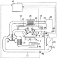
- FIG. 1 is a schematic diagram for explaining a system configuration according to the first embodiment of the present invention.
- the system of this embodiment includes a spark ignition type internal combustion engine 2 to which a control device is applied.
- the internal combustion engine 2 uses gasoline as a fuel, and can be preferably used as a power source of a vehicle, for example.
- the internal combustion engine 2 performs a stoichiometric combustion operation in which an air-fuel ratio is in the vicinity of a stoichiometric air-fuel ratio (hereinafter referred to as “stoichiometric”) and an air-fuel mixture that is significantly leaner than the stoichiometric air-fuel ratio in a predetermined lean combustion operation region. It is possible to switch between the lean combustion operation for burning.
- 1 shows only one cylinder of the internal combustion engine 2, the internal combustion engine 2 includes a plurality of cylinders. The number of cylinders and the cylinder arrangement of the internal combustion engine 2 are not particularly limited.
- An in-cylinder injector 4 and a spark plug 6 are provided in each cylinder of the internal combustion engine 2.
- the in-cylinder injector 4 is installed so as to inject fuel into each cylinder of the internal combustion engine 2.
- a port injector that injects fuel into the intake port may be used.
- Each cylinder of the internal combustion engine 2 is provided with an intake valve 8 and an exhaust valve 10.
- a variable valve mechanism (not shown) for controlling the opening and closing of each of the intake valve 8 and the exhaust valve 10 is installed.
- An air cleaner 20 is attached in the vicinity of the inlet of the intake passage 12. Near the downstream of the air cleaner 20, an air flow meter 22 that outputs a signal corresponding to the flow rate of air sucked into the intake passage 12 is provided.
- a turbocharger compressor 24 is installed downstream of the air flow meter 22.
- An intercooler 26 for cooling the compressed air is provided downstream of the compressor 24 in the intake passage 12.
- An electronically controlled throttle valve 28 is provided downstream of the intercooler 26.
- a surge tank 30 is provided downstream of the throttle valve 28.
- the system of FIG. 1 has an ISC (Idle Speed Control) path 32 connecting the upstream side of the throttle valve 28 and the downstream side of the throttle valve 28 in the intake path 12.
- ISC Inner Speed Control
- one end of the ISC passage 32 is connected to the intake passage 12 downstream of the air cleaner 20 and upstream of the compressor 24.
- the other end of the ISC passage 32 is connected to the intake passage 12 downstream of the surge tank 30.
- An ISC valve 34 that opens and closes the ISC passage 32 is installed in the ISC passage 32.
- the ISC valve 34 is a valve for adjusting the flow rate of the gas flowing through the ISC passage 32 by changing the cross-sectional area of the ISC passage 32 by controlling the opening degree to a predetermined opening degree.
- an exhaust turbine 36 of a supercharger is installed in the exhaust passage 14.
- a catalyst 38 for purifying exhaust gas is installed downstream of the exhaust turbine 36, and a silencer 40 is installed downstream of the catalyst 38.
- the first pressure sensor 42 is installed in the vicinity of the connection portion of the ISC passage 32 between the air cleaner 20 of the intake passage 12 and the compressor 24.
- the first pressure sensor 42 acquires a first pressure P1 that is an intake pressure in the vicinity of a connection portion between the ISC passage 32 and the intake passage 12.
- the second pressure sensor 44 is installed in the surge tank 30. Based on the output of the second pressure sensor 44, the second pressure P2 that is the intake pressure in the surge tank 30 is acquired.
- the system of FIG. 1 includes an ECU (Electronic Control Unit) 50.
- the control device of the present invention is realized as a function of the ECU 50.
- Various sensors for detecting the operation state of the internal combustion engine 2 such as the air flow meter 22 and the first and second pressure sensors 42 and 44 described above are connected to the ECU 50.
- the ECU 50 is connected to various actuators for controlling the operation state of the internal combustion engine 2 such as the throttle valve 28, the in-cylinder injector 4, and the spark plug 6 described above.
- the ECU 50 controls the operating state of the internal combustion engine 2 by executing a control program stored in advance in the memory in accordance with the parameter relating to the operating state of the internal combustion engine from which the output of each sensor has been acquired.
- the control executed by the control device in the present embodiment includes control related to the open / closed state of the ISC valve 34.
- the control device acquires a required torque and an expected generated torque (hereinafter also referred to as an estimated torque) that is a torque that can be generated in the internal combustion engine.
- the required torque and the expected generated torque are calculated by a known method, and the calculation method is not limited here. Further, the required torque and the expected generated torque are not limited to those directly calculated by the control device in the present embodiment, but may be input from a system arranged at a higher level of the control device.
- the control device performs control to fully open the ISC valve 34 on the condition that the acquired expected generated torque is greater than the required torque and the second pressure P2 is greater than the first pressure P1.
- the ISC valve 34 is fully opened while the second pressure P2 on the downstream side of the intake passage 12 is larger than the first pressure P1 on the upstream side, thereby causing the intake air to flow backward to the upstream side and reducing the internal pressure of the surge tank 30. be able to. This suppresses torque fluctuations when the expected generated torque exceeds the required torque.
- the ISC valve 34 is fully opened when the above condition (that is, the expected generated torque is greater than the required torque and the second pressure P2 is greater than the first pressure P1) is satisfied.
- the valve opening control is also referred to as “ISC valve full opening control”. This condition is also referred to as “ISC valve fully open condition”.
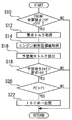
- FIG. 2 is a flowchart illustrating a control routine executed by the control device in the first embodiment of the present invention.
- the routine of FIG. 2 is a routine that is repeatedly executed at regular intervals during operation of the internal combustion engine 2.
- the routine of FIG. 2 it is first determined whether or not the ISC valve full open prohibition flag is OFF (S10).
- the ISC valve full open prohibition flag is a flag that is switched ON / OFF by a process that will be described later. While this flag is ON, ISC valve full open control is prohibited. Therefore, in step S10, when it is not recognized that the ISC valve full open prohibition flag is OFF, the current process is temporarily ended.
- step S10 if it is determined in step S10 that the ISC valve full open prohibition flag is OFF, then the required torque is acquired (S12). Next, an engine control target value is acquired (S14).
- the engine control target value is, for example, the currently set target opening of the throttle valve 28, the target ignition timing, the target opening of the ISC valve 34, and the like.
- an expected generated torque is calculated according to these control target values (S16).
- step S18 it is determined whether or not the expected generated torque calculated in step S16 is larger than the required torque acquired in step S12 (S18).
- step S18 when it is not recognized that the expected generated torque is larger than the required torque, the current process is temporarily ended.
- step S18 determines whether or not the expected generated torque is greater than the required torque. If it is determined in step S18 that the expected generated torque is greater than the required torque, it is next determined whether or not the second pressure P2 is greater than the first pressure P1 (S20). In step S20, when it is not recognized that the second pressure P2 is higher than the first pressure P1, the current process ends.
- step S20 if it is recognized in step S20 that the second pressure P2 is greater than the first pressure P1, the ISC valve 34 is fully opened (S22).
- the ISC valve 34 is fully opened while the second pressure P2 is greater than the first pressure P1, a portion of the intake air passes through the ISC passage 32 and from the downstream side of the surge tank 30 in the intake passage 12 to the intake passage. 12 flows backward to the upstream side. Thereby, a surge tank internal pressure falls and a torque is suppressed. Thereafter, the current process ends.
- the internal combustion engine 2 of the present embodiment is an internal combustion engine capable of a lean combustion operation.
- the intake port shape is optimized in order to stably perform lean combustion, and the swirl flow and tumble flow generated in the cylinder are designed to be strengthened.
- the intake air flows backward through the ISC passage 32.
- the flow of intake air in the intake passage 12 also changes greatly.
- the swirl flow and tumble flow generated in the cylinder are insufficient, in particular, the lean combustion limit is lowered, or the lean combustion becomes unstable.
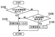
- FIG. 3 is a flowchart for illustrating a control routine executed by the control device in the first embodiment of the present invention.
- the routine of FIG. 3 is a routine that is repeatedly executed at regular intervals during the operation of the internal combustion engine 2.
- it is first determined whether or not the ISC valve full open control is being executed (S102). If it is determined in step S102 that the ISC valve full open control is being executed, the target air-fuel ratio is set to stoichiometric (S104). Thereby, the lean combustion operation is prohibited. Thereafter, the current process ends.
- step S106 determines whether the conditions for the lean combustion operation are currently satisfied.
- the lean combustion operation condition is stored in advance in the control device. Specifically, for example, conditions such that the engine speed of the internal combustion engine 2 is equal to or less than a predetermined value can be given.
- step S106 if the establishment of the lean combustion operation condition is not recognized, the process proceeds to step S104, and the target air-fuel ratio is set to stoichiometric. Thereafter, the current process ends.
- step S106 determines whether the lean combustion operation condition is satisfied. If it is determined in step S106 that the lean combustion operation condition is satisfied, then the target air-fuel ratio is set to a predetermined lean air-fuel ratio (S108). Thereafter, the current process ends.
- the control device of the present embodiment prohibits the ISC valve full open control during the lean combustion operation. That is, when the lean combustion operation is performed, the ISC valve full open control is not performed even in an operation state in which the ISC valve full open condition is satisfied.
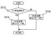
- FIG. 4 is a flowchart for explaining a control routine executed by the control device in the first embodiment of the present invention.
- the routine of FIG. 4 is a routine that is repeatedly executed at regular intervals during the operation of the internal combustion engine 2. In the routine of FIG. 4, it is first determined whether or not a lean combustion operation is being performed (S112).
- the ISC valve full open prohibition flag is turned ON (S114).
- the ISC valve full-open prohibition flag is a flag used for determining whether or not the ISC valve full-open control can be executed in step S10 of the routine shown in FIG. 2 described above. Full open control is prohibited. Thereafter, the current process ends.
- the ISC valve 34 is controlled according to a normal control program for the ISC valve 34 separately stored in the ECU 50. This process prohibits the ISC valve full open control during the lean combustion operation. However, even during the lean combustion operation, the ISC valve 34 may be opened by the normal control flag and may be fully opened.
- step S112 if it is not recognized in step S112 that the lean combustion operation is currently being performed, the ISC valve full open prohibition flag is turned OFF (S116). Accordingly, the execution of the routine of FIG. 2 is permitted, and when the ISC valve fully open condition determined by the routine of FIG. 2 is satisfied, the ISC valve 34 is fully opened. Thereafter, the current process ends.
- the switching to the lean combustion operation is prohibited during the execution of the ISC valve full opening control, while the ISC valve full opening control is prohibited during the lean combustion operation.
- torque fluctuation can be suppressed outside the lean combustion operation region while ensuring stable combustion in the lean combustion operation region.
- the opening of the ISC valve 34 is fully opened when the ISC valve fully opening condition is satisfied.
- the present invention is not limited to this, and the opening of the ISC valve 34 may be larger than a predetermined reference opening.
- the reference opening can be appropriately set to an opening that is large enough to reduce the generated torque by causing the intake air to flow backward at an early stage by opening the ISC valve. The same applies to other embodiments.
- the system according to the present embodiment has been described with respect to the case where the first pressure sensor 42 and the second pressure sensor 44 are provided, and the first pressure P1 and the second pressure P2 are acquired based on the outputs of these sensors.
- the present invention may be configured not to have both or one of the first pressure sensor 42 and the second pressure sensor 44.
- the estimated value of the pressure of each part can be used as the first pressure P1 and the second pressure P2. The same applies to other embodiments.
- control device executes both the routines of FIG. 3 and FIG. 4 to prohibit switching to the lean combustion operation during the ISC valve full open control, and during the lean combustion operation.
- the case where execution of the valve full open control is prohibited has been described.
- the present invention is not limited to executing both controls, and may perform only one of the controls. The same applies to other embodiments.
- FIG. FIG. 5 is a diagram for explaining a system according to the second embodiment of the present invention.
- the system of FIG. 5 has the same configuration as the system of FIG. 1 except that it has a high-pressure EGR device.
- the system of FIG. 5 is a high pressure loop-exhaust gas (HPL-EGR) that recirculates part of the exhaust gas as EGR gas from the exhaust passage 14 to the intake passage 12 in addition to the system of FIG. Recirculation device.
- HPL-EGR high pressure loop-exhaust gas
- the high-pressure EGR device has a high-pressure EGR pipe 60, a high-pressure EGR cooler 62 provided in the high-pressure EGR pipe 60, and a high-pressure EGR valve 64.
- One end of the high-pressure EGR pipe 60 is connected upstream of the exhaust turbine 36 in the exhaust passage 14, and the other end is connected between the surge tank 30 and the intake manifold (not shown) of the intake passage 12.
- the high pressure EGR valve 64 is a valve that can change the cross-sectional area of the high pressure EGR pipe 60 by adjusting the opening degree. That is, the flow rate of the EGR gas flowing through the high pressure EGR pipe 60 is controlled by the opening degree control of the high pressure EGR valve 64.
- the control device controls the opening degree of the EGR valve 64 by issuing a control signal for controlling the opening degree of the high pressure EGR valve 64 according to a control program stored in advance.
- the control device includes control for prohibiting the ISC valve full open control during the high pressure EGR valve open.
- the control device of the second embodiment fully closes the high pressure EGR valve 64 and then opens the ISC valve fully when there is an ISC valve full open control execution command with the high pressure EGR valve 64 open. Execute control.
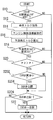
- FIG. 6 is a flowchart for explaining a control routine executed by the control device in the second embodiment of the present invention.
- the routine shown in FIG. 6 is executed in place of the routine shown in FIG. 2, and is repeatedly executed at regular intervals.
- the routine in FIG. 6 is the same as the routine in FIG. 2 except that the processes in steps S202 to S206 are provided between the process in step S20 and the process in step S22 of the routine in FIG.
- step S202 If it is determined in step S202 that the high pressure EGR valve 64 is open, then a control signal for fully closing the high pressure EGR valve 64 is issued (S204). Next, it is determined whether or not the high pressure EGR valve 64 is fully closed (S206). That is, whether or not the high-pressure EGR valve 64 is actually fully closed is confirmed by the control command in step S204. In step S206, when it is not recognized that the high pressure EGR valve 64 is closed, the current process is terminated as it is. That is, the ISC valve 34 is not fully opened, and the current process ends.
- step S206 if it is determined in step S206 that the high-pressure EGR valve 64 is fully closed, or if it is determined in step S202 that the EGR valve is not open, then ISC valve full-open control is executed ( S22). Thereafter, the current process ends.
- the ISC valve full open control is prohibited while the high pressure EGR valve 64 is open, and the high pressure EGR valve 64 is closed even when the ISC valve full open control condition is satisfied.
- ISC valve full open control is performed after valve-opening.
- the present invention is not limited to this, and the prohibition control of the ISC valve full-opening control during the lean combustion operation and the prohibition control of the lean combustion operation during the ISC valve full-opening control according to the first embodiment are combined. It may not be. In such a case, for example, it may be determined whether or not the ISC valve full open prohibition flag in step S10 in the routine of FIG. 6 is OFF and / or the routine of FIG. The same applies to other embodiments.
- steps S12 to S20 and S22 of FIG. 6 is executed, thereby realizing the “control means for performing valve opening control” of the present invention, and the processing of steps S202 to S206 is performed.
- the “means for prohibiting opening of the EGR valve” of the present invention is realized, and the processing of step S204 is executed to realize “means for closing the EGR valve”.
- FIG. 7 is a diagram for explaining the overall configuration of the system according to the third embodiment of the present invention.
- the system of FIG. 7 is the same as the system of FIG. 1 except that it has a low pressure EGR device.
- the system of FIG. 7 has a low pressure EGR device (LPL-EGR: Low Pressure Loop-Exhaust Gas Recirculation) device.
- LPL-EGR Low Pressure Loop-Exhaust Gas Recirculation
- the low pressure EGR device includes a low pressure EGR pipe 66, a low pressure EGR cooler 68 provided in the low pressure EGR pipe 66, and a low pressure EGR valve 70.
- One end of the low pressure EGR pipe 66 is connected to the downstream side of the catalyst 38 in the exhaust passage 14, and the other end is connected to the upstream side of the compressor 24 in the intake passage 12.
- the low pressure EGR valve 70 is a valve that can change the flow path cross-sectional area of the low pressure EGR pipe 66 by adjusting the opening degree thereof. That is, the flow rate of the EGR gas flowing through the low pressure EGR pipe 66 is controlled by the opening degree control of the low pressure EGR valve 70.
- the EGR gas residual amount in the intake passage 12 is estimated, and when it is recognized that the residual EGR has disappeared, control is performed to permit full opening of the ISC valve.
- the EGR gas residual amount is determined according to the piping volume downstream from the low pressure EGR valve 70, the flow rate of the intake air, and the like.
- FIG. 8 is a flowchart for explaining a control routine executed by the control device in Embodiment 3 of the present invention.
- the routine of FIG. 8 is a routine that is executed at regular intervals instead of the routine of FIG.
- the routine in FIG. 8 is the same as the routine in FIG. 2 except that steps S302 to S308 are included between steps S20 and S22.
- step S302 it is next determined whether or not the low-pressure EGR valve 70 is being opened. If it is determined in step S302 that the low pressure EGR valve 70 is being opened, then the low pressure EGR valve 70 is fully closed (S304). The control device closes the low pressure EGR valve 70 by issuing a predetermined control signal.
- the EGR gas residual amount is then calculated. (S306).
- the EGR gas residual amount is the amount of EGR gas remaining in the intake passage 12 at the time of calculation, the elapsed time since the low pressure EGR valve 70 was closed, the intake air amount, and the downstream of the low pressure EGR valve 70. According to the volume of the intake passage 12, etc., it is obtained according to an arithmetic expression or the like stored in advance in the control device.
- step S306 it is determined whether or not the EGR gas residual amount calculated in step S306 is less than or equal to zero (S308). If it is not recognized that the EGR gas residual amount is less than or equal to zero, the current process ends as it is. That is, in the process up to S20, the condition for executing the ISC valve full open control is confirmed, but it is determined that the EGR gas remains in the intake passage 12, so the ISC valve is not fully opened and remains as it is. The current process is temporarily terminated, and then the routine of FIG. 8 is repeated again.
- step S308 if it is determined in step S308 that the residual amount of EGR gas is zero or less, the ISC valve 34 is then fully opened (S22). Thereafter, the current process ends.
- the ISC valve 70 in the case of using the low pressure EGR device, even after the low pressure EGR valve 70 is closed, the ISC valve is not fully opened while the EGR gas remains. Therefore, it is possible to more reliably prevent the EGR gas from flowing backward from the ISC passage 32 and being released from the air cleaner 20 to the outside.
- the present invention is not limited to this, and may have the high-pressure EGR device described in FIG.
- the control related to the high pressure EGR may be executed as described in the second embodiment according to the routine of FIG.
- the high-pressure EGR device as described in the routine of FIG. 8 the residual amount of EGR gas after the valve closing is calculated, and when the residual amount becomes zero, the ISC valve is fully opened. Also good. The same applies to other embodiments.
- the case where the control related to the lean combustion operation of the first embodiment and the control related to the low pressure EGR valve of the present embodiment are combined has been described. That is, according to the routine of FIG. 8, the execution of the ISC valve full open control is prohibited during the lean combustion operation by the process of S10, and the ISC valve is fully opened while the EGR gas remains by the processes of S302 to S308. Execution of control is prohibited. Furthermore, the lean combustion operation during the ISC valve full-opening control is prohibited by executing the routine of FIG. 3 in combination. The same applies to other embodiments.
- the present invention is not limited to this, and the prohibition control of the ISC valve full-opening control during the lean combustion operation and the prohibition control of the lean combustion operation during the ISC valve full-opening control according to the first embodiment are combined. It is also possible not to do it. In such a case, for example, it may be determined whether or not the ISC valve full open prohibition flag in step S10 in the routine of FIG. 8 is OFF and / or the routine of FIG. The same applies to other embodiments.
- the processing of steps S12 to S20 and S22 of FIG. 8 is executed, thereby realizing the “control means for performing valve opening control” of the present invention, and the processing of steps S302 to S304.
- the “means for prohibiting the opening of the EGR valve” of the present invention is realized, and the processing of step S304 is executed to realize the “means for closing the EGR valve”.
- “valve opening control prohibiting means” is realized.
Abstract
An internal combustion engine according to the present invention is provided with a supercharger and an EGR device. In addition, the internal combustion engine comprises an ISC passage that connects the upstream side and the downstream side of a throttle valve in an intake passage and an ISC valve that regulates the amount of air that flows through the ISC passage. A control device according to the present invention performs valve opening control in which the opening degree of the ISC valve is set to be larger than a standard opening degree when the required torque that is required from the internal combustion engine is smaller than an estimated torque that the internal combustion engine is capable of generating, and prohibits the opening of an EGR valve of the EGR device during execution of the valve opening control.
Description
この発明は内燃機関の制御装置に関するものである。更に具体的には、内燃機関の吸気通路に、スロットル弁の上流側と下流側とを接続するバイパス通路を備える内燃機関の制御装置に関するものである。
The present invention relates to a control device for an internal combustion engine. More specifically, the present invention relates to a control device for an internal combustion engine provided with a bypass passage connecting an upstream side and a downstream side of a throttle valve to an intake passage of the internal combustion engine.
従来、例えば、特許文献1には過給機付きの内燃機関の制御装置が開示されている。また特許文献1には、要求トルクに応じて定められる目標吸気と実際の吸気量とが異なる場合に生じる出力変動を抑制するための点火時期の制御が提案されている。具体的に、特許文献1の制御装置は、内燃機関の運転中、目標吸気量より実際の吸気量が大きいオーバーシュート時には点火時期を遅角し、目標吸気量より実際の吸気量が小さいアンダーシュート時には点火時期を進角する制御を行う。
Conventionally, for example, Patent Document 1 discloses a control device for an internal combustion engine with a supercharger. Patent Document 1 proposes ignition timing control for suppressing output fluctuations that occur when the target intake air determined according to the required torque differs from the actual intake air amount. Specifically, the control device of Patent Document 1 retards the ignition timing during overshoot when the actual intake air amount is larger than the target intake air amount during operation of the internal combustion engine, and undershoots the actual intake air amount smaller than the target intake air amount. Sometimes control is performed to advance the ignition timing.
上記特許文献1の制御では、目標吸気量が実際の吸気量とは異なる場合に生じる出力変動を、点火時期の進角又は遅角により抑制する。しかし過給機を有する内燃機関の場合、過給領域では、ノッキングを抑制するため、点火時期がMBTより遅角側に設定されている場合がある。このような場合、点火時期の遅角限界までの余裕が少ない。このような場合には、実際の吸気量が目標吸気量より大きく出力トルクの低減が必要となっても、点火時期の遅角制御だけでは十分にトルク低減できないことが考えられる。
In the control of Patent Document 1, output fluctuation that occurs when the target intake air amount is different from the actual intake air amount is suppressed by the advance or retard of the ignition timing. However, in the case of an internal combustion engine having a supercharger, in order to suppress knocking in the supercharging region, the ignition timing may be set on the retard side from the MBT. In such a case, there is little margin to the retard limit of the ignition timing. In such a case, even if the actual intake air amount is larger than the target intake air amount and the output torque needs to be reduced, it is conceivable that the torque cannot be sufficiently reduced only by the retard control of the ignition timing.
ここで、スロットル弁の上流と下流とを接続するISC通路を有し、ISC通路にISC弁を有する内燃機関の場合、ISC弁を開弁してISC通路から吸入空気を上流側に逆流させることも考えられる。これにより筒内に流入する吸気量を減らすことができ、トルクを低減させることができる。
Here, in the case of an internal combustion engine having an ISC passage connecting the upstream and downstream of the throttle valve and having an ISC valve in the ISC passage, the ISC valve is opened and the intake air flows backward from the ISC passage upstream. Is also possible. As a result, the amount of intake air flowing into the cylinder can be reduced, and the torque can be reduced.
しかしこのようにISC弁を開弁する制御では、吸入空気がISC通路を逆流することとなる。このため運転状態によっては、EGRガスの逆流によりEGR率が目標値とずれ、燃焼が不安定となることも考えられる。
However, in the control for opening the ISC valve in this way, the intake air flows backward through the ISC passage. For this reason, depending on the operating state, the EGR rate may deviate from the target value due to the backflow of EGR gas, and combustion may become unstable.
この発明は、上記課題を解決することを目的とし、出力トルクを低減する要求がある場合において、ISC弁の制御による要求トルク実現により燃焼が不安定となるのを抑制するよう改良した内燃機関の制御装置を提供するものである。
An object of the present invention is to solve the above-mentioned problems, and in an internal combustion engine improved so as to suppress instability of combustion by realizing the required torque by controlling the ISC valve when there is a request to reduce the output torque. A control device is provided.
第1の発明は、上記の目的を達成するため、過給機を備える内燃機関の制御装置であって、
内燃機関の排気通路から吸気通路へ、排気の一部をEGRガスとして還流させるEGR装置と、
前記吸気通路に設置されたスロットル弁と、
前記吸気通路の、前記スロットル弁の上流側と下流側とを接続するISC通路と、
所定の開度に制御されることで前記ISC通路に流れる空気量を調節するISC弁と、
前記内燃機関に要求される要求トルクが、前記内燃機関で発生しうる推定トルクより小さい場合に、前記ISC弁の開度を基準開度より大きな開度とする開弁制御を実行する制御手段と、
前記開弁制御の実行中、EGR装置のEGR弁の開弁を禁止する手段と、
を備えるものである。 In order to achieve the above object, a first invention is a control device for an internal combustion engine including a supercharger,
An EGR device that recirculates part of the exhaust as EGR gas from the exhaust passage of the internal combustion engine to the intake passage;
A throttle valve installed in the intake passage;
An ISC passage connecting the upstream side and the downstream side of the throttle valve of the intake passage;
An ISC valve that adjusts the amount of air flowing through the ISC passage by being controlled to a predetermined opening;
Control means for performing valve-opening control to make the opening of the ISC valve larger than a reference opening when a required torque required for the internal combustion engine is smaller than an estimated torque that can be generated in the internal combustion engine; ,
Means for prohibiting the opening of the EGR valve of the EGR device during execution of the valve opening control;
Is provided.
ここで「基準開度」は、ISC弁が全開となる最大開度あるいは、その近傍の大きな開度に設定されることが望ましい。
Here, the “reference opening” is desirably set to the maximum opening at which the ISC valve is fully opened or a large opening in the vicinity thereof.
第2の発明は、第1の発明において、
前記EGR弁の開弁中に前記開弁制御の実行指令があった場合、前記開弁制御の実行前に前記EGR弁を閉弁する手段を、更に備えるものである。 According to a second invention, in the first invention,
When the execution command for the valve opening control is received during the opening of the EGR valve, the apparatus further includes means for closing the EGR valve before the execution of the valve opening control.
第3の発明は、第2の発明において、
前記EGR装置は、前記過給機のタービンより上流の前記排気通路から、前記過給機のコンプレッサより下流の前記吸気通路に、排気の一部を還流させる高圧EGR装置である。 According to a third invention, in the second invention,
The EGR device is a high-pressure EGR device that recirculates a part of exhaust gas from the exhaust passage upstream of the turbocharger turbine to the intake passage downstream of the compressor of the supercharger.
第4の発明は、第2の発明において、
前記EGR弁の閉弁後、前記吸気通路にEGRガスが残留している間、前記開弁制御の実行を禁止する開弁制御禁止手段を、更に備えるものである。 According to a fourth invention, in the second invention,
After the EGR valve is closed, valve opening control prohibiting means for prohibiting execution of the valve opening control while EGR gas remains in the intake passage is further provided.
第5の発明は、第3の発明において、
前記EGR装置は、前記過給機のタービンより下流の前記排気通路から、前記過給機のコンプレッサより上流の前記吸気通路に、排気の一部を還流させる低圧EGR装置である。 According to a fifth invention, in the third invention,
The EGR device is a low pressure EGR device that recirculates a part of exhaust gas from the exhaust passage downstream of the turbocharger turbine to the intake passage upstream of the turbocharger compressor.
ISC弁の開弁制御時には、吸気が上流側に逆流する。このため、ISC弁開弁時にEGR弁が開弁されると、逆流する吸気と共にEGRガスも上流側に逆流することとなる。従って、EGR率が目標とするEGR率よりも大きくなり、燃焼が不安定となることが考えられる。この点、第1から第5のいずれかの発明によれば、ISC弁の開弁中はEGR弁の開弁が禁止される。これによりISC弁の開弁制御が行われる場合にも、EGR率を安定させ、燃焼の安定化を図ることができる。
During intake control of the ISC valve, intake air flows backward upstream. For this reason, when the EGR valve is opened when the ISC valve is opened, the EGR gas also flows back upstream along with the backflowing intake air. Therefore, it is conceivable that the EGR rate becomes larger than the target EGR rate and the combustion becomes unstable. In this regard, according to any one of the first to fifth inventions, the opening of the EGR valve is prohibited during the opening of the ISC valve. As a result, even when valve opening control of the ISC valve is performed, the EGR rate can be stabilized and combustion can be stabilized.
以下、図面を参照して本発明の実施の形態について説明する。なお、各図において、同一または相当する部分には同一符号を付してその説明を簡略化ないし省略する。
Hereinafter, embodiments of the present invention will be described with reference to the drawings. In the drawings, the same or corresponding parts are denoted by the same reference numerals, and the description thereof is simplified or omitted.
実施の形態1.
[実施の形態1の構成]
図1は、本発明の実施の形態1のシステム構成を説明するための模式図である。本実施形態のシステムは、制御装置の適用対象となる火花点火式の内燃機関2を備えている。内燃機関2はガソリンを燃料とするものであり、例えば、車両の動力源として好ましく使用することができる。内燃機関2は、空燃比が理論空燃比(以下「ストイキ」)近傍の混合気を燃焼させるストイキ燃焼運転と、所定のリーン燃焼運転領域で理論空燃比より大幅にリーンな空燃比の混合気を燃焼させるリーン燃焼運転と、を切り替えて行うことができる。また、図1では、内燃機関2の1つの気筒のみを図示しているが、内燃機関2は複数の気筒を備えている。内燃機関2の気筒数および気筒配置は特に限定されるものではない。Embodiment 1 FIG.
[Configuration of Embodiment 1]
FIG. 1 is a schematic diagram for explaining a system configuration according to the first embodiment of the present invention. The system of this embodiment includes a spark ignition typeinternal combustion engine 2 to which a control device is applied. The internal combustion engine 2 uses gasoline as a fuel, and can be preferably used as a power source of a vehicle, for example. The internal combustion engine 2 performs a stoichiometric combustion operation in which an air-fuel ratio is in the vicinity of a stoichiometric air-fuel ratio (hereinafter referred to as “stoichiometric”) and an air-fuel mixture that is significantly leaner than the stoichiometric air-fuel ratio in a predetermined lean combustion operation region. It is possible to switch between the lean combustion operation for burning. 1 shows only one cylinder of the internal combustion engine 2, the internal combustion engine 2 includes a plurality of cylinders. The number of cylinders and the cylinder arrangement of the internal combustion engine 2 are not particularly limited.
[実施の形態1の構成]
図1は、本発明の実施の形態1のシステム構成を説明するための模式図である。本実施形態のシステムは、制御装置の適用対象となる火花点火式の内燃機関2を備えている。内燃機関2はガソリンを燃料とするものであり、例えば、車両の動力源として好ましく使用することができる。内燃機関2は、空燃比が理論空燃比(以下「ストイキ」)近傍の混合気を燃焼させるストイキ燃焼運転と、所定のリーン燃焼運転領域で理論空燃比より大幅にリーンな空燃比の混合気を燃焼させるリーン燃焼運転と、を切り替えて行うことができる。また、図1では、内燃機関2の1つの気筒のみを図示しているが、内燃機関2は複数の気筒を備えている。内燃機関2の気筒数および気筒配置は特に限定されるものではない。
[Configuration of Embodiment 1]
FIG. 1 is a schematic diagram for explaining a system configuration according to the first embodiment of the present invention. The system of this embodiment includes a spark ignition type
内燃機関2の各気筒には、筒内インジェクタ4及び点火プラグ6が設けられている。筒内インジェクタ4は、内燃機関2の各気筒内に燃料を噴射するように設置されている。図1の構成では、筒内インジェクタ4が設けられているが、吸気ポート内に燃料を噴射するポートインジェクタを用いるものであってもよい。内燃機関2の各気筒には吸気弁8及び排気弁10が設けられている。このシステムには、吸気弁8及び排気弁10それぞれの開閉を制御する可変動弁機構(図示せず)が設置されている。
An in-cylinder injector 4 and a spark plug 6 are provided in each cylinder of the internal combustion engine 2. The in-cylinder injector 4 is installed so as to inject fuel into each cylinder of the internal combustion engine 2. In the configuration of FIG. 1, the in-cylinder injector 4 is provided, but a port injector that injects fuel into the intake port may be used. Each cylinder of the internal combustion engine 2 is provided with an intake valve 8 and an exhaust valve 10. In this system, a variable valve mechanism (not shown) for controlling the opening and closing of each of the intake valve 8 and the exhaust valve 10 is installed.
各気筒には吸気通路12の下流側端部と、排気通路14の上流側端部とがそれぞれ連通している。吸気通路12の入口近傍には、エアクリーナ20が取り付けられている。エアクリーナ20の下流近傍には、吸気通路12に吸入される空気の流量に応じた信号を出力するエアフロメータ22が設けられている。エアフロメータ22の下流には、ターボ過給機のコンプレッサ24が設置されている。
The downstream end portion of the intake passage 12 and the upstream end portion of the exhaust passage 14 communicate with each cylinder. An air cleaner 20 is attached in the vicinity of the inlet of the intake passage 12. Near the downstream of the air cleaner 20, an air flow meter 22 that outputs a signal corresponding to the flow rate of air sucked into the intake passage 12 is provided. A turbocharger compressor 24 is installed downstream of the air flow meter 22.
吸気通路12のコンプレッサ24の下流には、圧縮された空気を冷却するインタークーラ26が設けられている。インタークーラ26の下流には、電子制御式のスロットル弁28が設けられている。スロットル弁28の下流にはサージタンク30が設けられている。
An intercooler 26 for cooling the compressed air is provided downstream of the compressor 24 in the intake passage 12. An electronically controlled throttle valve 28 is provided downstream of the intercooler 26. A surge tank 30 is provided downstream of the throttle valve 28.
図1のシステムは、吸気通路12の、スロットル弁28の上流側とスロットル弁28の下流側とを接続するISC(Idle Speed Control)通路32を有している。具体的にISC通路32の一端は、吸気通路12のエアクリーナ20の下流かつコンプレッサ24の上流に接続されている。ISC通路32の他端は、吸気通路12の、サージタンク30の下流に接続されている。ISC通路32には、ISC通路32を開閉するISC弁34が設置されている。ISC弁34は、その開度が所定の開度に制御されることでISC通路32の流路断面積を変化させ、ISC通路32に流れるガスの流量を調節するための弁である。
The system of FIG. 1 has an ISC (Idle Speed Control) path 32 connecting the upstream side of the throttle valve 28 and the downstream side of the throttle valve 28 in the intake path 12. Specifically, one end of the ISC passage 32 is connected to the intake passage 12 downstream of the air cleaner 20 and upstream of the compressor 24. The other end of the ISC passage 32 is connected to the intake passage 12 downstream of the surge tank 30. An ISC valve 34 that opens and closes the ISC passage 32 is installed in the ISC passage 32. The ISC valve 34 is a valve for adjusting the flow rate of the gas flowing through the ISC passage 32 by changing the cross-sectional area of the ISC passage 32 by controlling the opening degree to a predetermined opening degree.
排気通路14には、過給機の排気タービン36が設置されている。排気タービン36の下流には排気ガスを浄化するための触媒38が設置され、更にその下流に消音器40が設置されている。
In the exhaust passage 14, an exhaust turbine 36 of a supercharger is installed. A catalyst 38 for purifying exhaust gas is installed downstream of the exhaust turbine 36, and a silencer 40 is installed downstream of the catalyst 38.
図1のシステムは、第1圧力センサ42と第2圧力センサ44とを有している。第1圧力センサ42は、吸気通路12のエアクリーナ20とコンプレッサ24との間の、ISC通路32の接続部近傍に設置されている。第1圧力センサ42によって、ISC通路32と吸気通路12との接続部付近の吸気圧である第1圧力P1が取得される。第2圧力センサ44はサージタンク30内に設置されている。第2圧力センサ44の出力に基づき、サージタンク30内の吸気圧である第2圧力P2が取得される。
1 has a first pressure sensor 42 and a second pressure sensor 44. The first pressure sensor 42 is installed in the vicinity of the connection portion of the ISC passage 32 between the air cleaner 20 of the intake passage 12 and the compressor 24. The first pressure sensor 42 acquires a first pressure P1 that is an intake pressure in the vicinity of a connection portion between the ISC passage 32 and the intake passage 12. The second pressure sensor 44 is installed in the surge tank 30. Based on the output of the second pressure sensor 44, the second pressure P2 that is the intake pressure in the surge tank 30 is acquired.
図1のシステムは、ECU(Electronic Control Unit)50を備えている。本発明の制御装置は、ECU50の一機能として実現される。ECU50には、上述したエアフロメータ22、第1、第2圧力センサ42、44等の内燃機関2の運転状態を検知するための各種センサが接続されている。また、ECU50には、上述したスロットル弁28、筒内インジェクタ4、点火プラグ6等の内燃機関2の運転状態を制御する各種アクチュエータが接続されている。ECU50は、各センサの出力を取得された内燃機関の運転状態に関するパラメータに応じて、メモリに予め記憶された制御プログラムを実行することで、内燃機関2の運転状態を制御する。
The system of FIG. 1 includes an ECU (Electronic Control Unit) 50. The control device of the present invention is realized as a function of the ECU 50. Various sensors for detecting the operation state of the internal combustion engine 2 such as the air flow meter 22 and the first and second pressure sensors 42 and 44 described above are connected to the ECU 50. The ECU 50 is connected to various actuators for controlling the operation state of the internal combustion engine 2 such as the throttle valve 28, the in-cylinder injector 4, and the spark plug 6 described above. The ECU 50 controls the operating state of the internal combustion engine 2 by executing a control program stored in advance in the memory in accordance with the parameter relating to the operating state of the internal combustion engine from which the output of each sensor has been acquired.
[本実施の形態のISC弁全開制御の概要]
本実施の形態において制御装置が実行する制御には、ISC弁34の開閉状態に関する制御が含まれる。この制御において、制御装置は要求トルクと、内燃機関で発生し得るトルクである予想発生トルク(以下、推定トルクとも称する)とを取得する。要求トルクと予想発生トルクとは既知の手法により演算され、ここではその演算手法は限定されない。また、要求トルクと予想発生トルクとは、本実施の形態における制御装置が直接的に演算するものに限らず、制御装置の上位に配置されたシステムより入力されるものであってもよい。 [Overview of ISC valve full open control of this embodiment]
The control executed by the control device in the present embodiment includes control related to the open / closed state of theISC valve 34. In this control, the control device acquires a required torque and an expected generated torque (hereinafter also referred to as an estimated torque) that is a torque that can be generated in the internal combustion engine. The required torque and the expected generated torque are calculated by a known method, and the calculation method is not limited here. Further, the required torque and the expected generated torque are not limited to those directly calculated by the control device in the present embodiment, but may be input from a system arranged at a higher level of the control device.
本実施の形態において制御装置が実行する制御には、ISC弁34の開閉状態に関する制御が含まれる。この制御において、制御装置は要求トルクと、内燃機関で発生し得るトルクである予想発生トルク(以下、推定トルクとも称する)とを取得する。要求トルクと予想発生トルクとは既知の手法により演算され、ここではその演算手法は限定されない。また、要求トルクと予想発生トルクとは、本実施の形態における制御装置が直接的に演算するものに限らず、制御装置の上位に配置されたシステムより入力されるものであってもよい。 [Overview of ISC valve full open control of this embodiment]
The control executed by the control device in the present embodiment includes control related to the open / closed state of the
制御装置は、取得された予想発生トルクが要求トルクより大きいこと、かつ、第2圧力P2が第1圧力P1より大きいことを条件として、ISC弁34を全開とする制御を行う。吸気通路12の下流側の第2圧力P2が、上流側の第1圧力P1より大きい状態でISC弁34を全開とすることで、吸気を上流側に逆流させてサージタンク30の内圧を低下させることができる。これにより、予想発生トルクが要求トルクを上回る場合のトルク変動を抑制する。なお、以下の実施の形態において、上記条件(即ち、予想発生トルクが要求トルクより大きく、かつ、第2圧力P2が第1圧力P1より大きいこと)を満たす場合に、ISC弁34を全開とする開弁制御を「ISC弁全開制御」とも称することとする。また、この条件を、「ISC弁全開条件」とも称することとする。
The control device performs control to fully open the ISC valve 34 on the condition that the acquired expected generated torque is greater than the required torque and the second pressure P2 is greater than the first pressure P1. The ISC valve 34 is fully opened while the second pressure P2 on the downstream side of the intake passage 12 is larger than the first pressure P1 on the upstream side, thereby causing the intake air to flow backward to the upstream side and reducing the internal pressure of the surge tank 30. be able to. This suppresses torque fluctuations when the expected generated torque exceeds the required torque. In the following embodiment, the ISC valve 34 is fully opened when the above condition (that is, the expected generated torque is greater than the required torque and the second pressure P2 is greater than the first pressure P1) is satisfied. The valve opening control is also referred to as “ISC valve full opening control”. This condition is also referred to as “ISC valve fully open condition”.
図2は、本発明の実施の形態1において制御装置が実行する制御のルーチンについて説明するフローチャートである。図2のルーチンは、内燃機関2の運転中一定時間ごとに繰り返し実行されるルーチンである。図2のルーチンでは、まず、ISC弁全開禁止フラグがOFFとなっているか否かが判別される(S10)。ISC弁全開禁止フラグは、後述する処理により、ON/OFFが切り替えられるフラグであり、このフラグがONとなっている間、ISC弁全開制御が禁止される。従って、ステップS10において、ISC弁全開禁止フラグがOFFとなっていることが認められない場合には、今回の処理は一旦終了する。
FIG. 2 is a flowchart illustrating a control routine executed by the control device in the first embodiment of the present invention. The routine of FIG. 2 is a routine that is repeatedly executed at regular intervals during operation of the internal combustion engine 2. In the routine of FIG. 2, it is first determined whether or not the ISC valve full open prohibition flag is OFF (S10). The ISC valve full open prohibition flag is a flag that is switched ON / OFF by a process that will be described later. While this flag is ON, ISC valve full open control is prohibited. Therefore, in step S10, when it is not recognized that the ISC valve full open prohibition flag is OFF, the current process is temporarily ended.
一方、ステップS10において、ISC弁全開禁止フラグがOFFであることが認められると、次に要求トルクが取得される(S12)。次に、エンジン制御目標値が取得される(S14)。エンジン制御目標値は、例えば、現在設定されているスロットル弁28の目標開度、目標点火時期、ISC弁34の目標開度等である。次に、これらの制御目標値に応じて、予想発生トルクが算出される(S16)。
On the other hand, if it is determined in step S10 that the ISC valve full open prohibition flag is OFF, then the required torque is acquired (S12). Next, an engine control target value is acquired (S14). The engine control target value is, for example, the currently set target opening of the throttle valve 28, the target ignition timing, the target opening of the ISC valve 34, and the like. Next, an expected generated torque is calculated according to these control target values (S16).
次に、ステップS16において算出された予想発生トルクが、ステップS12において取得された要求トルクより大きいか否かが判別される(S18)。ステップS18において、予想発生トルクが要求トルクより大きいことが認められない場合、今回の処理は一旦終了する。
Next, it is determined whether or not the expected generated torque calculated in step S16 is larger than the required torque acquired in step S12 (S18). In step S18, when it is not recognized that the expected generated torque is larger than the required torque, the current process is temporarily ended.
一方、ステップS18において予想発生トルクが要求トルクより大きいことが認められると、次に、第2圧力P2が第1圧力P1より大きいか否かが判別される(S20)。ステップS20において、第2圧力P2が第1圧力P1より大きいことが認められない場合には、今回の処理は終了する。
On the other hand, if it is determined in step S18 that the expected generated torque is greater than the required torque, it is next determined whether or not the second pressure P2 is greater than the first pressure P1 (S20). In step S20, when it is not recognized that the second pressure P2 is higher than the first pressure P1, the current process ends.
一方ステップS20において、第2圧力P2が第1圧力P1より大きいことが認められると、ISC弁34が全開とされる(S22)。第2圧力P2が第1圧力P1より大きい状態でISC弁34が全開とされることで、吸気の一部はISC通路32を通って、吸気通路12のサージタンク30より下流側から、吸気通路12の上流側に逆流する。これにより、サージタンク内圧が低下し、トルクが抑制される。その後、今回の処理は終了する。
On the other hand, if it is recognized in step S20 that the second pressure P2 is greater than the first pressure P1, the ISC valve 34 is fully opened (S22). When the ISC valve 34 is fully opened while the second pressure P2 is greater than the first pressure P1, a portion of the intake air passes through the ISC passage 32 and from the downstream side of the surge tank 30 in the intake passage 12 to the intake passage. 12 flows backward to the upstream side. Thereby, a surge tank internal pressure falls and a torque is suppressed. Thereafter, the current process ends.
[本実施の形態のリーン燃焼運転の禁止制御の概要]
ところで、本実施の形態の内燃機関2はリーン燃焼運転が可能な内燃機関である。このようなリーン燃焼運転可能な内燃機関の場合、リーン燃焼を安定して行うために吸気ポート形状が最適化され、筒内に発生するスワール流やタンブル流を強化するように設計されている。しかし、ISC弁全開制御の実行中は、ISC通路32を介して吸気が上流側に逆流する。このためISC弁全開制御中は、吸気通路12内での吸気の流れも大きく変化する。その結果、筒内に発生するスワール流やタンブル流が不足し、特に、リーン燃焼限界が低下し、あるいは、リーン燃焼が不安定となることが考えられる。 [Outline of Lean Combustion Control of the Present Embodiment]
By the way, theinternal combustion engine 2 of the present embodiment is an internal combustion engine capable of a lean combustion operation. In the case of such an internal combustion engine capable of lean combustion operation, the intake port shape is optimized in order to stably perform lean combustion, and the swirl flow and tumble flow generated in the cylinder are designed to be strengthened. However, during the execution of the ISC valve fully open control, the intake air flows backward through the ISC passage 32. For this reason, during the ISC valve full open control, the flow of intake air in the intake passage 12 also changes greatly. As a result, it is conceivable that the swirl flow and tumble flow generated in the cylinder are insufficient, in particular, the lean combustion limit is lowered, or the lean combustion becomes unstable.
ところで、本実施の形態の内燃機関2はリーン燃焼運転が可能な内燃機関である。このようなリーン燃焼運転可能な内燃機関の場合、リーン燃焼を安定して行うために吸気ポート形状が最適化され、筒内に発生するスワール流やタンブル流を強化するように設計されている。しかし、ISC弁全開制御の実行中は、ISC通路32を介して吸気が上流側に逆流する。このためISC弁全開制御中は、吸気通路12内での吸気の流れも大きく変化する。その結果、筒内に発生するスワール流やタンブル流が不足し、特に、リーン燃焼限界が低下し、あるいは、リーン燃焼が不安定となることが考えられる。 [Outline of Lean Combustion Control of the Present Embodiment]
By the way, the
従って本実施の形態において制御装置は、ISC弁全開制御中のリーン燃焼運転を禁止する制御を実行する。図3は、本発明の実施の形態1において制御装置が実行する制御のルーチンについて説明するためのフローチャートである。図3のルーチンは内燃機関2の運転中、一定時間ごとに繰り返し実行されるルーチンである。図3のルーチンでは、まず、ISC弁全開制御の実行中であるか否かが判別される(S102)。ステップS102において、ISC弁全開制御の実行中であることが認められた場合には、目標空燃比がストイキに設定される(S104)。これにより、リーン燃焼運転は禁止される。その後、今回の処理は終了する。
Therefore, in the present embodiment, the control device executes a control for prohibiting the lean combustion operation during the ISC valve full open control. FIG. 3 is a flowchart for illustrating a control routine executed by the control device in the first embodiment of the present invention. The routine of FIG. 3 is a routine that is repeatedly executed at regular intervals during the operation of the internal combustion engine 2. In the routine of FIG. 3, it is first determined whether or not the ISC valve full open control is being executed (S102). If it is determined in step S102 that the ISC valve full open control is being executed, the target air-fuel ratio is set to stoichiometric (S104). Thereby, the lean combustion operation is prohibited. Thereafter, the current process ends.
一方、ステップS102において、ISC弁全開制御の実行中であることが認められない場合には、現在、S106においてリーン燃焼運転の条件が成立しているか否かが判別される。リーン燃焼運転条件は、予め制御装置に記憶されている。具体的には、例えば内燃機関2の機関回転数が所定以下であるなどの条件が挙げられる。
On the other hand, if it is not determined in step S102 that the ISC valve fully open control is being executed, it is determined in step S106 whether the conditions for the lean combustion operation are currently satisfied. The lean combustion operation condition is stored in advance in the control device. Specifically, for example, conditions such that the engine speed of the internal combustion engine 2 is equal to or less than a predetermined value can be given.
ステップS106において、リーン燃焼運転条件の成立が認められない場合には、ステップS104に進み、目標空燃比がストイキに設定される。その後今回の処理が終了する。
In step S106, if the establishment of the lean combustion operation condition is not recognized, the process proceeds to step S104, and the target air-fuel ratio is set to stoichiometric. Thereafter, the current process ends.
一方、ステップS106において、リーン燃焼運転条件の成立が認められた場合には、次に、目標空燃比が、所定のリーン空燃比に設定される(S108)。その後今回の処理が終了する。
On the other hand, if it is determined in step S106 that the lean combustion operation condition is satisfied, then the target air-fuel ratio is set to a predetermined lean air-fuel ratio (S108). Thereafter, the current process ends.
以上の処理により、ISC弁全開制御の実行中は、リーン燃焼運転が禁止され、ストイキ燃焼運転が実行される。これによりISC弁全開制御中の燃焼の安定化を図ることができる。
Through the above processing, the lean combustion operation is prohibited and the stoichiometric combustion operation is executed during the execution of the ISC valve full open control. Thereby, stabilization of combustion during ISC valve full open control can be aimed at.
[本実施の形態のISC弁全開制御の禁止制御の概要]
更に、本実施の形態の制御装置は、リーン燃焼運転時には、ISC弁全開制御を禁止する。つまり、リーン燃焼運転が行われている時には、ISC弁全開条件が成立するような運転状態であっても、ISC弁全開制御が行われない。 [Outline of Prohibition Control of ISC Valve Full Open Control of Embodiment]
Furthermore, the control device of the present embodiment prohibits the ISC valve full open control during the lean combustion operation. That is, when the lean combustion operation is performed, the ISC valve full open control is not performed even in an operation state in which the ISC valve full open condition is satisfied.
図4は、本発明の実施の形態1において制御装置が実行する制御のルーチンについて説明するためのフローチャートである。図4のルーチンは内燃機関2の運転中、一定時間ごとに繰り返し実行されるルーチンである。図4のルーチンでは、まず、リーン燃焼運転中であるか否かが判別される(S112)。
FIG. 4 is a flowchart for explaining a control routine executed by the control device in the first embodiment of the present invention. The routine of FIG. 4 is a routine that is repeatedly executed at regular intervals during the operation of the internal combustion engine 2. In the routine of FIG. 4, it is first determined whether or not a lean combustion operation is being performed (S112).
ステップS112においてリーン燃焼運転中であることが認められると、次に、ISC弁全開禁止フラグがONとされる(S114)。ISC弁全開禁止フラグは、上述した図2のルーチンのステップS10において、ISC弁全開制御実行可否の判断に用いられるフラグであり、このフラグがONとされることで、図2のルーチンによるISC弁全開制御は禁止される。その後、今回の処理は終了する。この場合、ISC弁34は、別途ECU50に記憶されたISC弁34の通常時の制御プログラムに従って制御される。なお、この処理によりリーン燃焼運転時にはISC弁全開制御は禁止される。但し、リーン燃焼運転中であっても、ISC弁34が通常時の制御フラグにより開弁され、全開とされる場合もある。
If it is determined in step S112 that the lean combustion operation is being performed, then the ISC valve full open prohibition flag is turned ON (S114). The ISC valve full-open prohibition flag is a flag used for determining whether or not the ISC valve full-open control can be executed in step S10 of the routine shown in FIG. 2 described above. Full open control is prohibited. Thereafter, the current process ends. In this case, the ISC valve 34 is controlled according to a normal control program for the ISC valve 34 separately stored in the ECU 50. This process prohibits the ISC valve full open control during the lean combustion operation. However, even during the lean combustion operation, the ISC valve 34 may be opened by the normal control flag and may be fully opened.
一方、ステップS112において、現在リーン燃焼運転中であることが認められない場合、ISC弁全開禁止フラグがOFFとされる(S116)。これにより図2のルーチンの実行が許可され、図2のルーチンで判別されるISC弁全開条件が成立した場合には、ISC弁34が全開とされる。その後、今回の処理は終了する。
On the other hand, if it is not recognized in step S112 that the lean combustion operation is currently being performed, the ISC valve full open prohibition flag is turned OFF (S116). Accordingly, the execution of the routine of FIG. 2 is permitted, and when the ISC valve fully open condition determined by the routine of FIG. 2 is satisfied, the ISC valve 34 is fully opened. Thereafter, the current process ends.
以上説明したように、本実施の形態によれば、ISC弁全開制御実行中は、リーン燃焼運転への切り替えが禁止される一方、リーン燃焼運転中は、ISC弁全開制御が禁止される。これにより、リーン燃焼運転領域で、安定的な燃焼を確保しつつ、リーン燃焼運転領域外ではトルク変動の抑制を図ることができる。
As described above, according to the present embodiment, the switching to the lean combustion operation is prohibited during the execution of the ISC valve full opening control, while the ISC valve full opening control is prohibited during the lean combustion operation. Thus, torque fluctuation can be suppressed outside the lean combustion operation region while ensuring stable combustion in the lean combustion operation region.
なお、本実施の形態では、ISC弁全開条件が成立した場合に、ISC弁34の開度を最大開度である全開にする場合について説明した。しかし、本発明はこれに限られるものではなく、ISC弁34の開度を所定の基準開度より大きくするものであってもよい。ここで基準開度は、ISC弁の開弁により早期に吸気を逆流させて発生トルク低減を図ることができる程度に大きな開度に、適宜設定することができる。これは他の実施の形態においても同様である。
In the present embodiment, the case has been described in which the opening of the ISC valve 34 is fully opened when the ISC valve fully opening condition is satisfied. However, the present invention is not limited to this, and the opening of the ISC valve 34 may be larger than a predetermined reference opening. Here, the reference opening can be appropriately set to an opening that is large enough to reduce the generated torque by causing the intake air to flow backward at an early stage by opening the ISC valve. The same applies to other embodiments.
また、本実施の形態のシステムは、第1圧力センサ42と第2圧力センサ44とを備え、これらセンサの出力に基づき第1圧力P1及び第2圧力P2を取得する場合について説明した。しかし本発明は、第1圧力センサ42及び第2圧力センサ44の両者又は一方を有さない構成であってもよい。このような場合、第1圧力P1と第2圧力P2として、各部分の圧力の推定値を用いることができる。これは他の実施の形態においても同様である。
Further, the system according to the present embodiment has been described with respect to the case where the first pressure sensor 42 and the second pressure sensor 44 are provided, and the first pressure P1 and the second pressure P2 are acquired based on the outputs of these sensors. However, the present invention may be configured not to have both or one of the first pressure sensor 42 and the second pressure sensor 44. In such a case, the estimated value of the pressure of each part can be used as the first pressure P1 and the second pressure P2. The same applies to other embodiments.
また、本実施の形態では、制御装置は図3及び図4のルーチンの双方を実行することで、ISC弁全開制御中にはリーン燃焼運転への切り替えを禁止し、リーン燃焼運転中にはISC弁全開制御の実行を禁止する場合について説明した。しかし、本発明は、両制御を実行するものに限られず、いずれか一方の制御のみを行うものであってもよい。これは他の実施の形態においても同様である。
Further, in the present embodiment, the control device executes both the routines of FIG. 3 and FIG. 4 to prohibit switching to the lean combustion operation during the ISC valve full open control, and during the lean combustion operation. The case where execution of the valve full open control is prohibited has been described. However, the present invention is not limited to executing both controls, and may perform only one of the controls. The same applies to other embodiments.
実施の形態2.
図5は、本発明の実施の形態2におけるシステムについて説明するための図である。図5に示されるように、図5のシステムは、高圧EGR装置を有する点を除き、図1のシステムと同一の構成を有している。具体的に、図5のシステムは、図1のシステムに加え、排気通路14から吸気通路12へ、排気ガスの一部をEGRガスとして還流する高圧EGR(HPL-EGR:High Pressure Loop - Exhaust Gas Recirculation)装置を有している。Embodiment 2. FIG.
FIG. 5 is a diagram for explaining a system according to the second embodiment of the present invention. As shown in FIG. 5, the system of FIG. 5 has the same configuration as the system of FIG. 1 except that it has a high-pressure EGR device. Specifically, the system of FIG. 5 is a high pressure loop-exhaust gas (HPL-EGR) that recirculates part of the exhaust gas as EGR gas from theexhaust passage 14 to the intake passage 12 in addition to the system of FIG. Recirculation device.
図5は、本発明の実施の形態2におけるシステムについて説明するための図である。図5に示されるように、図5のシステムは、高圧EGR装置を有する点を除き、図1のシステムと同一の構成を有している。具体的に、図5のシステムは、図1のシステムに加え、排気通路14から吸気通路12へ、排気ガスの一部をEGRガスとして還流する高圧EGR(HPL-EGR:High Pressure Loop - Exhaust Gas Recirculation)装置を有している。
FIG. 5 is a diagram for explaining a system according to the second embodiment of the present invention. As shown in FIG. 5, the system of FIG. 5 has the same configuration as the system of FIG. 1 except that it has a high-pressure EGR device. Specifically, the system of FIG. 5 is a high pressure loop-exhaust gas (HPL-EGR) that recirculates part of the exhaust gas as EGR gas from the
高圧EGR装置は、高圧EGR配管60、高圧EGR配管60に設けられた高圧EGRクーラ62と高圧EGR弁64とを有している。高圧EGR配管60は、その一端が、排気通路14の、排気タービン36より上流側に接続され、他端が、吸気通路12の、サージタンク30とインテークマニホールド(図示せず)との間に接続されている。高圧EGR弁64はその開度を調整することで高圧EGR配管60の流路断面積を変更できる弁である。即ち高圧EGR弁64の開度制御により高圧EGR配管60を流れるEGRガスの流量が制御される。
The high-pressure EGR device has a high-pressure EGR pipe 60, a high-pressure EGR cooler 62 provided in the high-pressure EGR pipe 60, and a high-pressure EGR valve 64. One end of the high-pressure EGR pipe 60 is connected upstream of the exhaust turbine 36 in the exhaust passage 14, and the other end is connected between the surge tank 30 and the intake manifold (not shown) of the intake passage 12. Has been. The high pressure EGR valve 64 is a valve that can change the cross-sectional area of the high pressure EGR pipe 60 by adjusting the opening degree. That is, the flow rate of the EGR gas flowing through the high pressure EGR pipe 60 is controlled by the opening degree control of the high pressure EGR valve 64.
制御装置は予め記憶された制御プログラムに従って、高圧EGR弁64の開度を制御する制御信号を発することでEGR弁64の開度を制御する。ところで高圧EGR使用中にISC弁全開制御を実行すると、未浄化のEGRガスがISC通路32を介してエアクリーナ20側に逆流し、エアクリーナ20内に滞留したり、大気に放出されたりすることが考えられる。
The control device controls the opening degree of the EGR valve 64 by issuing a control signal for controlling the opening degree of the high pressure EGR valve 64 according to a control program stored in advance. By the way, if the ISC valve full open control is executed while the high pressure EGR is being used, unpurified EGR gas may flow back to the air cleaner 20 side via the ISC passage 32 and stay in the air cleaner 20 or be released to the atmosphere. It is done.
そこで、本実施の形態において制御装置は、高圧EGR弁開弁中のISC弁全開制御を禁止する制御が含まれる。具体的に、実施の形態2の制御装置は、高圧EGR弁64が開いている状態でISC弁全開制御の実行指令があった場合には、高圧EGR弁64を全閉し、その後ISC弁全開制御を実行する。
Therefore, in the present embodiment, the control device includes control for prohibiting the ISC valve full open control during the high pressure EGR valve open. Specifically, the control device of the second embodiment fully closes the high pressure EGR valve 64 and then opens the ISC valve fully when there is an ISC valve full open control execution command with the high pressure EGR valve 64 open. Execute control.
図6は、本発明の実施の形態2において制御装置が実行する制御のルーチンについて説明するためのフローチャートである。図6のルーチンは、図2のルーチンに替えて実行され、一定時間ごとに繰り返し実行されるルーチンである。図6のルーチンは、図2のルーチンのステップS20の処理とステップS22の処理との間に、ステップS202~S206の処理を有する点を除き、図2のルーチンと同一である。
FIG. 6 is a flowchart for explaining a control routine executed by the control device in the second embodiment of the present invention. The routine shown in FIG. 6 is executed in place of the routine shown in FIG. 2, and is repeatedly executed at regular intervals. The routine in FIG. 6 is the same as the routine in FIG. 2 except that the processes in steps S202 to S206 are provided between the process in step S20 and the process in step S22 of the routine in FIG.
図6のルーチンでは、ステップS20までの処理においてISC弁全開条件の成立が認められると、S20の処理の後、まず、高圧EGR弁64が開弁中であるか否かが判別される(S202)。
In the routine of FIG. 6, if the establishment of the ISC valve fully open condition is confirmed in the processing up to step S20, it is first determined whether or not the high pressure EGR valve 64 is being opened after the processing of S20 (S202). ).
ステップS202において、高圧EGR弁64が開弁中であると判別された場合、次に、高圧EGR弁64を全閉とする制御信号が出される(S204)。次に、高圧EGR弁64が全閉とされたか否かが判別される(S206)。即ち、ステップS204の制御指令により、高圧EGR弁64が実際に全閉とされたか否かが確認される。ステップS206において、高圧EGR弁64が閉弁されたことが認められない場合には、今回の処理はこのまま終了される。即ち、ISC弁34は全開とされず、今回の処理は終了する。
If it is determined in step S202 that the high pressure EGR valve 64 is open, then a control signal for fully closing the high pressure EGR valve 64 is issued (S204). Next, it is determined whether or not the high pressure EGR valve 64 is fully closed (S206). That is, whether or not the high-pressure EGR valve 64 is actually fully closed is confirmed by the control command in step S204. In step S206, when it is not recognized that the high pressure EGR valve 64 is closed, the current process is terminated as it is. That is, the ISC valve 34 is not fully opened, and the current process ends.
一方、ステップS206において、高圧EGR弁64の全閉が認められた場合、又は、ステップS202においてEGR弁が開弁中ではないと判別された場合、次に、ISC弁全開制御が実行される(S22)。その後、今回の処理は終了する。
On the other hand, if it is determined in step S206 that the high-pressure EGR valve 64 is fully closed, or if it is determined in step S202 that the EGR valve is not open, then ISC valve full-open control is executed ( S22). Thereafter, the current process ends.
以上説明したように、本実施の形態では、高圧EGR弁64が開弁している間はISC弁全開制御が禁止され、ISC弁全開制御条件が成立した場合にも、高圧EGR弁64を閉弁した後でISC弁全開制御が実行される。これにより、未浄化のEGRガスの逆流を抑制することができ、エアクリーナ20内に溜まるEGRガスによりEGR率が増加し燃焼が不安定となることを抑制することができる。また、未浄化のEGRガスが逆流により吸気口の外への放出されるのを抑制することができ、エミッションの悪化を防止することができる。
As described above, in the present embodiment, the ISC valve full open control is prohibited while the high pressure EGR valve 64 is open, and the high pressure EGR valve 64 is closed even when the ISC valve full open control condition is satisfied. ISC valve full open control is performed after valve-opening. Thereby, the back flow of unpurified EGR gas can be suppressed, and it is possible to suppress the EGR rate from being increased by the EGR gas accumulated in the air cleaner 20 and the combustion becoming unstable. In addition, it is possible to suppress the unpurified EGR gas from being released to the outside of the intake port due to the backflow, and it is possible to prevent the emission from deteriorating.
なお、本実施の形態では、実施の形態1に説明したリーン燃焼運転に関する制御と、本実施の形態の高圧EGR弁に関する制御とを組み合わせて行う場合について説明した。つまり、図6のルーチンによれば、図4のルーチンでリーン燃焼運転中にはISC弁全開禁止フラグがONとされるため、S10の処理によりISC弁全開制御の実行が禁止され、かつ、S202~S206の処理によりEGR弁64の開弁中はISC弁全開制御の実行が禁止される。更に、図3のルーチンが組み合わされて実行されることでISC弁全開制御中のリーン燃焼運転が禁止される。これは他の実施の形態においても同様である。
In the present embodiment, a case has been described in which the control related to the lean combustion operation described in the first embodiment and the control related to the high pressure EGR valve of the present embodiment are performed in combination. That is, according to the routine of FIG. 6, since the ISC valve full open prohibition flag is turned ON during the lean combustion operation in the routine of FIG. 4, the execution of the ISC valve full open control is prohibited by the processing of S10, and S202 Through the processing of S206, execution of the ISC valve full open control is prohibited while the EGR valve 64 is open. Furthermore, the lean combustion operation during the ISC valve full-opening control is prohibited by executing the routine of FIG. 3 in combination. The same applies to other embodiments.
しかし、本発明はこれに限られるものではなく、実施の形態1のリーン燃焼運転時のISC弁全開制御の禁止制御及びISC弁全開制御中のリーン燃焼運転の禁止制御の両方、又は一方を組み合わせないものとしてもよい。このような場合、例えば、図6のルーチンにおけるステップS10のISC弁全開禁止フラグがOFFであるか否かの判別及び/又は図3のルーチンを行わないこととすればよい。これは他の実施の形態においても同様である。
However, the present invention is not limited to this, and the prohibition control of the ISC valve full-opening control during the lean combustion operation and the prohibition control of the lean combustion operation during the ISC valve full-opening control according to the first embodiment are combined. It may not be. In such a case, for example, it may be determined whether or not the ISC valve full open prohibition flag in step S10 in the routine of FIG. 6 is OFF and / or the routine of FIG. The same applies to other embodiments.
なお、本実施の形態において、図6のステップS12~S20およびS22の処理が実行されることで、本発明の「開弁制御を実行する制御手段」が実現し、ステップS202~S206の処理が実行されることで、本発明の「EGR弁の開弁を禁止する手段」が実現し、ステップS204の処理が実行されることで「EGR弁を閉弁する手段」が実現する。
In the present embodiment, the processing of steps S12 to S20 and S22 of FIG. 6 is executed, thereby realizing the “control means for performing valve opening control” of the present invention, and the processing of steps S202 to S206 is performed. When executed, the “means for prohibiting opening of the EGR valve” of the present invention is realized, and the processing of step S204 is executed to realize “means for closing the EGR valve”.
実施の形態3.
図7は本発明の実施の形態3のシステムの全体構成を説明するための図である。図7のシステムは、低圧EGR装置を有する点を除き、図1のシステムと同一である。図7のシステムは、低圧EGR装置(LPL-EGR:Low Pressure Loop - Exhaust Gas Recirculation)装置を有している。 Embodiment 3 FIG.
FIG. 7 is a diagram for explaining the overall configuration of the system according to the third embodiment of the present invention. The system of FIG. 7 is the same as the system of FIG. 1 except that it has a low pressure EGR device. The system of FIG. 7 has a low pressure EGR device (LPL-EGR: Low Pressure Loop-Exhaust Gas Recirculation) device.
図7のシステムにおいて、低圧EGR装置は、低圧EGR配管66、低圧EGR配管66に設けられた低圧EGRクーラ68と低圧EGR弁70とを有している。低圧EGR配管66は、その一端が、排気通路14の触媒38より下流側に接続され、他端が、吸気通路12の、コンプレッサ24より上流側に接続されている。低圧EGR弁70は、その開度を調整することで低圧EGR配管66の流路断面積を変更できる弁である。即ち低圧EGR弁70の開度制御により低圧EGR配管66を流れるEGRガスの流量が制御される。
7, the low pressure EGR device includes a low pressure EGR pipe 66, a low pressure EGR cooler 68 provided in the low pressure EGR pipe 66, and a low pressure EGR valve 70. One end of the low pressure EGR pipe 66 is connected to the downstream side of the catalyst 38 in the exhaust passage 14, and the other end is connected to the upstream side of the compressor 24 in the intake passage 12. The low pressure EGR valve 70 is a valve that can change the flow path cross-sectional area of the low pressure EGR pipe 66 by adjusting the opening degree thereof. That is, the flow rate of the EGR gas flowing through the low pressure EGR pipe 66 is controlled by the opening degree control of the low pressure EGR valve 70.
図7に示されるように、低圧EGR装置の場合、吸気通路12のコンプレッサ24より上流側に低圧EGR配管66の一端が接続されている。従って、高圧EGR装置の場合に比べて、低圧EGR装置によるEGRガスの還流を停止した場合にも、低圧EGR弁70閉弁後に吸気通路12内に残るEGRガスの残留時間が長くなる。従って、低圧EGR弁70が閉弁とされていても、EGRガスが吸気通路12内に残留している状態でISC弁全開制御が実行されれば、残留EGRガスがエアクリーナ20側に逆流し、外部に排出される恐れがある。
7, in the case of the low pressure EGR device, one end of the low pressure EGR pipe 66 is connected to the upstream side of the compressor 24 in the intake passage 12. Therefore, even when the recirculation of the EGR gas by the low pressure EGR device is stopped, the remaining time of the EGR gas remaining in the intake passage 12 after the low pressure EGR valve 70 is closed becomes longer than in the case of the high pressure EGR device. Therefore, even if the low pressure EGR valve 70 is closed, if the ISC valve full open control is executed in a state where the EGR gas remains in the intake passage 12, the residual EGR gas flows back to the air cleaner 20 side, There is a risk of being discharged to the outside.
そこで、本実施の形態では低圧EGR弁70閉弁後の、吸気通路12内のEGRガス残留量を推定し、残留EGRがなくなったと認められた場合に、ISC弁の全開を許可する制御を行う。なお、ここで、EGRガス残留量は、低圧EGR弁70より下流の配管容積や、吸入空気の流量等に応じて求められる。
Therefore, in the present embodiment, after the low pressure EGR valve 70 is closed, the EGR gas residual amount in the intake passage 12 is estimated, and when it is recognized that the residual EGR has disappeared, control is performed to permit full opening of the ISC valve. . Here, the EGR gas residual amount is determined according to the piping volume downstream from the low pressure EGR valve 70, the flow rate of the intake air, and the like.
図8は、本発明の実施の形態3において制御装置が実行する制御のルーチンについて説明するためのフローチャートである。図8のルーチンは、図6のルーチンに替えて、一定時間ごとに実行されるルーチンである。図8のルーチンは、ステップS20とS22との間に、ステップS302~S308の処理を有する点を除き、図2のルーチンと同じものである。
FIG. 8 is a flowchart for explaining a control routine executed by the control device in Embodiment 3 of the present invention. The routine of FIG. 8 is a routine that is executed at regular intervals instead of the routine of FIG. The routine in FIG. 8 is the same as the routine in FIG. 2 except that steps S302 to S308 are included between steps S20 and S22.
図8のルーチンでは、ステップS20までの処理により、ISC弁全開条件の成立が認められると、次に、低圧EGR弁70が開弁中であるか否かが判別される(S302)。ステップS302において、低圧EGR弁70が開弁中であることが認められた場合、次に、低圧EGR弁70が全閉とされる(S304)。制御装置は、所定の制御信号を発することで低圧EGR弁70を閉弁させる。
In the routine of FIG. 8, if the establishment of the ISC valve full-open condition is confirmed by the processing up to step S20, it is next determined whether or not the low-pressure EGR valve 70 is being opened (S302). If it is determined in step S302 that the low pressure EGR valve 70 is being opened, then the low pressure EGR valve 70 is fully closed (S304). The control device closes the low pressure EGR valve 70 by issuing a predetermined control signal.
ステップS304において低圧EGR弁70が全閉とされた後、又は、ステップS302において低圧EGR弁70が開弁中であることが認められなかった場合には、次に、EGRガス残留量が算出される(S306)。ここでEGRガス残留量は、算出時点で吸気通路12内に残っているEGRガス量であり、低圧EGR弁70が閉弁されてからの経過時間、吸入空気量、及び低圧EGR弁70下流の吸気通路12の容積等に応じ、予め制御装置に記憶された演算式等に従って求められる。
After the low-pressure EGR valve 70 is fully closed in step S304, or if it is not recognized in step S302 that the low-pressure EGR valve 70 is being opened, the EGR gas residual amount is then calculated. (S306). Here, the EGR gas residual amount is the amount of EGR gas remaining in the intake passage 12 at the time of calculation, the elapsed time since the low pressure EGR valve 70 was closed, the intake air amount, and the downstream of the low pressure EGR valve 70. According to the volume of the intake passage 12, etc., it is obtained according to an arithmetic expression or the like stored in advance in the control device.
次に、ステップS306において算出されたEGRガス残留量がゼロ以下であるか否かが判別される(S308)。EGRガス残留量がゼロ以下であることが認められない場合には、今回の処理はこのまま終了する。即ち、S20までの処理でISC弁全開制御実行条件の成立が認められる状態であるが、吸気通路12内にEGRガスが残留していると判断されるため、ISC弁は全開とされず、このまま今回の処理は一旦終了し、その後、図8のルーチンは再び繰り返される。
Next, it is determined whether or not the EGR gas residual amount calculated in step S306 is less than or equal to zero (S308). If it is not recognized that the EGR gas residual amount is less than or equal to zero, the current process ends as it is. That is, in the process up to S20, the condition for executing the ISC valve full open control is confirmed, but it is determined that the EGR gas remains in the intake passage 12, so the ISC valve is not fully opened and remains as it is. The current process is temporarily terminated, and then the routine of FIG. 8 is repeated again.
一方、ステップS308において、EGRガス残留量がゼロ以下であることが認められると、次に、ISC弁34が全開とされる(S22)。その後、今回の処理は終了する。
On the other hand, if it is determined in step S308 that the residual amount of EGR gas is zero or less, the ISC valve 34 is then fully opened (S22). Thereafter, the current process ends.
以上説明したように、本実施の形態によれば、低圧EGR装置を用いるものの場合、低圧EGR弁70の閉弁後も、EGRガスが残留している間はISC弁の全開が禁止される。従って、ISC通路32からEGRガスが逆流し、エアクリーナ20から外部へ放出されるのを、より確実に防ぐことができる。
As described above, according to the present embodiment, in the case of using the low pressure EGR device, even after the low pressure EGR valve 70 is closed, the ISC valve is not fully opened while the EGR gas remains. Therefore, it is possible to more reliably prevent the EGR gas from flowing backward from the ISC passage 32 and being released from the air cleaner 20 to the outside.
なお、本実施の形態では、EGR装置として低圧EGR装置のみを有する場合について説明した。しかし本発明はこれに限られるものではなく、図5において説明した高圧EGR装置をも有するものであってもよい。この場合、高圧EGRに関連する制御は、図6のルーチンに従い、実施の形態2で説明したように実行するものであってもよい。また、高圧EGR装置についても、図8のルーチンに説明したように、閉弁後のEGRガスの残留量を算出し、残留量がゼロとなった時点で、ISC弁の全開を行うようにしてもよい。これは、他の実施の形態においても同様である。
In the present embodiment, the case where only the low pressure EGR device is provided as the EGR device has been described. However, the present invention is not limited to this, and may have the high-pressure EGR device described in FIG. In this case, the control related to the high pressure EGR may be executed as described in the second embodiment according to the routine of FIG. As for the high-pressure EGR device, as described in the routine of FIG. 8, the residual amount of EGR gas after the valve closing is calculated, and when the residual amount becomes zero, the ISC valve is fully opened. Also good. The same applies to other embodiments.
また、実施の形態3についても、実施の形態1のリーン燃焼運転に関する制御と、本実施の形態の低圧EGR弁に関する制御とが組み合わされた場合について説明した。つまり、図8のルーチンによれば、S10の処理によりリーン燃焼運転中にはISC弁全開制御の実行が禁止され、かつ、S302~S308の処理によりEGRガスが残留している間、ISC弁全開制御の実行が禁止される。更に、図3のルーチンが組み合わされて実行されることでISC弁全開制御中のリーン燃焼運転が禁止される。これは他の実施の形態においても同様である。
Also, in the third embodiment, the case where the control related to the lean combustion operation of the first embodiment and the control related to the low pressure EGR valve of the present embodiment are combined has been described. That is, according to the routine of FIG. 8, the execution of the ISC valve full open control is prohibited during the lean combustion operation by the process of S10, and the ISC valve is fully opened while the EGR gas remains by the processes of S302 to S308. Execution of control is prohibited. Furthermore, the lean combustion operation during the ISC valve full-opening control is prohibited by executing the routine of FIG. 3 in combination. The same applies to other embodiments.
しかし、本発明はこれに限られるものではなく、実施の形態1のリーン燃焼運転時のISC弁全開制御の禁止制御及びISC弁全開制御中のリーン燃焼運転の禁止制御の両方、又は一方を組み合わせて行わないものとしてもよい。このような場合、例えば、図8のルーチンにおけるステップS10のISC弁全開禁止フラグがOFFであるか否かの判別及び/又は図3のルーチンを行わないこととすればよい。これは他の実施の形態においても同様である。
However, the present invention is not limited to this, and the prohibition control of the ISC valve full-opening control during the lean combustion operation and the prohibition control of the lean combustion operation during the ISC valve full-opening control according to the first embodiment are combined. It is also possible not to do it. In such a case, for example, it may be determined whether or not the ISC valve full open prohibition flag in step S10 in the routine of FIG. 8 is OFF and / or the routine of FIG. The same applies to other embodiments.
なお、本実施の形態3において、図8のステップS12~S20およびS22の処理が実行されることで、本発明の「開弁制御を実行する制御手段」が実現し、ステップS302~S304の処理が実行されることで、本発明の「EGR弁の開弁を禁止する手段」が実現し、ステップS304の処理が実行されることで「EGR弁を閉弁する手段」が実現し、ステップS306~S308の処理が実行されることで、「開弁制御禁止手段」が実現する。
In the third embodiment, the processing of steps S12 to S20 and S22 of FIG. 8 is executed, thereby realizing the “control means for performing valve opening control” of the present invention, and the processing of steps S302 to S304. Is executed, the “means for prohibiting the opening of the EGR valve” of the present invention is realized, and the processing of step S304 is executed to realize the “means for closing the EGR valve”. By executing the processing of S308, “valve opening control prohibiting means” is realized.
なお、以上の実施の形態において各要素の個数、数量、量、範囲等の数に言及した場合、特に明示した場合や原理的に明らかにその数に特定される場合を除いて、その言及した数に、この発明が限定されるものではない。また、この実施の形態において説明する構造や方法等は、特に明示した場合や明らかに原理的にそれに特定される場合を除いて、この発明に必ずしも必須のものではない。
In the above embodiment, when referring to the number of each element, quantity, quantity, range, etc., the reference is made unless otherwise specified or the number is clearly specified in principle. The invention is not limited to the numbers. The structure, method, and the like described in this embodiment are not necessarily essential to the present invention unless otherwise specified or clearly specified in principle.
2 内燃機関
4 筒内インジェクタ
6 点火プラグ
8 吸気弁
10 排気弁
12 吸気通路
14 排気通路
20 エアクリーナ
22 エアフロメータ
24 コンプレッサ
26 インタークーラ
28 スロットル弁
30 サージタンク
32 ISC通路
34 ISC弁
36 排気タービン
38 触媒
40 消音器
42 第1圧力センサ
44 第2圧力センサ
50 ECU
60 高圧EGR配管
62 高圧EGRクーラ
64 高圧EGR弁
66 低圧EGR配管
68 低圧EGRクーラ
70 低圧EGR弁 DESCRIPTION OFSYMBOLS 2 Internal combustion engine 4 In-cylinder injector 6 Spark plug 8 Intake valve 10 Exhaust valve 12 Intake passage 14 Exhaust passage 20 Air cleaner 22 Air flow meter 24 Compressor 26 Intercooler 28 Throttle valve 30 Surge tank 32 ISC passage 34 ISC valve 36 Exhaust turbine 38 Catalyst 40 Silencer 42 First pressure sensor 44 Second pressure sensor 50 ECU
60 High pressure EGR piping 62 High pressure EGR cooler 64 Highpressure EGR valve 66 Low pressure EGR piping 68 Low pressure EGR cooler 70 Low pressure EGR valve
4 筒内インジェクタ
6 点火プラグ
8 吸気弁
10 排気弁
12 吸気通路
14 排気通路
20 エアクリーナ
22 エアフロメータ
24 コンプレッサ
26 インタークーラ
28 スロットル弁
30 サージタンク
32 ISC通路
34 ISC弁
36 排気タービン
38 触媒
40 消音器
42 第1圧力センサ
44 第2圧力センサ
50 ECU
60 高圧EGR配管
62 高圧EGRクーラ
64 高圧EGR弁
66 低圧EGR配管
68 低圧EGRクーラ
70 低圧EGR弁 DESCRIPTION OF
60 High pressure EGR piping 62 High pressure EGR cooler 64 High
Claims (5)
- 過給機を備える内燃機関の制御装置であって、
内燃機関の排気通路から吸気通路へ、排気の一部をEGRガスとして還流させるEGR装置と、
前記吸気通路に設置されたスロットル弁と、
前記吸気通路の、前記スロットル弁の上流側と下流側とを接続するISC通路と、
所定の開度に制御されることで前記ISC通路に流れる空気量を調節するISC弁と、
前記内燃機関に要求される要求トルクが、前記内燃機関で発生しうる推定トルクより小さい場合に、前記ISC弁の開度を基準開度より大きな開度とする開弁制御を実行する制御手段と、
前記開弁制御の実行中、EGR装置のEGR弁の開弁を禁止する手段と、
を備えることを特徴とする内燃機関の制御装置。 A control device for an internal combustion engine including a supercharger,
An EGR device that recirculates part of the exhaust as EGR gas from the exhaust passage of the internal combustion engine to the intake passage;
A throttle valve installed in the intake passage;
An ISC passage connecting the upstream side and the downstream side of the throttle valve of the intake passage;
An ISC valve that adjusts the amount of air flowing through the ISC passage by being controlled to a predetermined opening;
Control means for performing valve-opening control to make the opening of the ISC valve larger than a reference opening when a required torque required for the internal combustion engine is smaller than an estimated torque that can be generated in the internal combustion engine; ,
Means for prohibiting the opening of the EGR valve of the EGR device during execution of the valve opening control;
A control device for an internal combustion engine, comprising: - 前記EGR弁の開弁中に前記開弁制御の実行指令があった場合、前記開弁制御の実行前に前記EGR弁を閉弁する手段を、
更に備えることを特徴とする請求項1に記載の内燃機関の制御装置。 Means for closing the EGR valve before the execution of the valve opening control when there is a command to execute the valve opening control while the EGR valve is opened;
The control device for an internal combustion engine according to claim 1, further comprising: - 前記過給機は、前記吸気通路の設置されたコンプレッサと前記排気通路の配置されたタービンとにより構成され、
前記EGR装置は、前記タービンより上流の前記排気通路から、前記コンプレッサより下流の前記吸気通路に、排気の一部を還流させる高圧EGR装置であることを特徴とする請求項2に記載の内燃機関の制御装置。 The supercharger is composed of a compressor in which the intake passage is installed and a turbine in which the exhaust passage is arranged,
3. The internal combustion engine according to claim 2, wherein the EGR device is a high-pressure EGR device that recirculates a part of exhaust gas from the exhaust passage upstream from the turbine to the intake passage downstream from the compressor. Control device. - 前記EGR弁の閉弁後、前記吸気通路にEGRガスが残留している間、前記開弁制御の実行を禁止する開弁制御禁止手段を、
更に備えることを特徴とする請求項2に記載の内燃機関の制御装置。 After the EGR valve is closed, valve opening control prohibiting means for prohibiting execution of the valve opening control while EGR gas remains in the intake passage,
The control device for an internal combustion engine according to claim 2, further comprising: - 前記過給機は、前記吸気通路の設置されたコンプレッサと前記排気通路の配置されたタービンとにより構成され、
前記EGR装置は、前記タービンより下流の前記排気通路から、前記コンプレッサより上流の前記吸気通路に、排気の一部を還流させる低圧EGR装置であることを特徴とする請求項4に記載の内燃機関の制御装置。 The supercharger is composed of a compressor in which the intake passage is installed and a turbine in which the exhaust passage is arranged,
5. The internal combustion engine according to claim 4, wherein the EGR device is a low-pressure EGR device that recirculates a part of exhaust gas from the exhaust passage downstream of the turbine to the intake passage upstream of the compressor. Control device.
Priority Applications (2)
| Application Number | Priority Date | Filing Date | Title |
|---|---|---|---|
| US14/780,013 US9644553B2 (en) | 2013-03-27 | 2014-01-08 | Control device for internal combustion engine |
| EP14772783.8A EP2998549B1 (en) | 2013-03-27 | 2014-01-08 | Control device for internal combustion engine |
Applications Claiming Priority (2)
| Application Number | Priority Date | Filing Date | Title |
|---|---|---|---|
| JP2013066968 | 2013-03-27 | ||
| JP2013-066968 | 2013-03-27 |
Publications (1)
| Publication Number | Publication Date |
|---|---|
| WO2014156209A1 true WO2014156209A1 (en) | 2014-10-02 |
Family
ID=51623218
Family Applications (4)
| Application Number | Title | Priority Date | Filing Date |
|---|---|---|---|
| PCT/JP2014/050140 WO2014156209A1 (en) | 2013-03-27 | 2014-01-08 | Control device for internal combustion engine |
| PCT/JP2014/050139 WO2014156208A1 (en) | 2013-03-27 | 2014-01-08 | Control device for internal combustion engine |
| PCT/JP2014/050141 WO2014156210A1 (en) | 2013-03-27 | 2014-01-08 | Control device for internal combustion engine |
| PCT/JP2014/050142 WO2014156211A1 (en) | 2013-03-27 | 2014-01-08 | Control device for internal combustion engine |
Family Applications After (3)
| Application Number | Title | Priority Date | Filing Date |
|---|---|---|---|
| PCT/JP2014/050139 WO2014156208A1 (en) | 2013-03-27 | 2014-01-08 | Control device for internal combustion engine |
| PCT/JP2014/050141 WO2014156210A1 (en) | 2013-03-27 | 2014-01-08 | Control device for internal combustion engine |
| PCT/JP2014/050142 WO2014156211A1 (en) | 2013-03-27 | 2014-01-08 | Control device for internal combustion engine |
Country Status (4)
| Country | Link |
|---|---|
| US (4) | US20160047350A1 (en) |
| EP (4) | EP2998552B1 (en) |
| JP (1) | JP6156485B2 (en) |
| WO (4) | WO2014156209A1 (en) |
Families Citing this family (6)
| Publication number | Priority date | Publication date | Assignee | Title |
|---|---|---|---|---|
| WO2014156209A1 (en) * | 2013-03-27 | 2014-10-02 | トヨタ自動車株式会社 | Control device for internal combustion engine |
| KR20170139926A (en) * | 2016-06-10 | 2017-12-20 | 현대자동차주식회사 | Engine systme having exahust gas recirculation apparatus and control mehtod using the same |
| US10273965B2 (en) * | 2016-08-08 | 2019-04-30 | Borgwarner Inc. | Method of extended thermodynamic turbine mapping via compressor inlet throttling |
| JP6816833B2 (en) * | 2017-12-22 | 2021-01-20 | 日産自動車株式会社 | Internal combustion engine and its control method |
| US11560829B2 (en) * | 2020-01-02 | 2023-01-24 | Caterpillar Inc. | Recirculation system for a power system that includes a plurality of turbochargers |
| CN111677594B (en) * | 2020-05-12 | 2021-09-10 | 天津大学 | Rapid air storage and supply control method for supercharged engine air system |
Citations (9)
| Publication number | Priority date | Publication date | Assignee | Title |
|---|---|---|---|---|
| JPH07217475A (en) * | 1994-01-31 | 1995-08-15 | Mazda Motor Corp | Engine control device |
| JP2001073845A (en) * | 1999-09-06 | 2001-03-21 | Toyota Motor Corp | Combustion control device of internal-combustion engine |
| JP2001090543A (en) * | 1999-09-20 | 2001-04-03 | Unisia Jecs Corp | Control device for engine with supercharger |
| JP2004346917A (en) | 2003-05-26 | 2004-12-09 | Toyota Motor Corp | Internal combustion engine control device |
| JP2005083362A (en) * | 2003-09-11 | 2005-03-31 | Toyota Motor Corp | Controller for internal combustion engine |
| JP2006183643A (en) * | 2004-12-28 | 2006-07-13 | Toyota Motor Corp | Supercharging system for internal combustion engine |
| JP2007255194A (en) * | 2006-03-20 | 2007-10-04 | Toyota Motor Corp | Control device of internal combustion engine |
| WO2010109667A1 (en) * | 2009-03-27 | 2010-09-30 | 本田技研工業株式会社 | Controller for plant |
| JP2012102617A (en) | 2010-11-08 | 2012-05-31 | Daihatsu Motor Co Ltd | Internal combustion engine |
Family Cites Families (54)
| Publication number | Priority date | Publication date | Assignee | Title |
|---|---|---|---|---|
| JPS53146026A (en) * | 1977-05-26 | 1978-12-19 | Nissan Motor Co Ltd | Internal combustion engine with supercharging pressure controller |
| JPS5977059A (en) * | 1982-10-26 | 1984-05-02 | Nissan Motor Co Ltd | Air regulator device of fuel injection type internal-combustion engine equipped with turbo-charger |
| JPS59115444A (en) * | 1982-12-21 | 1984-07-03 | Toyota Motor Corp | Electronic control of linear solenoid type idle speed control valve for engine equipped with supercharger |
| JPS59115445A (en) * | 1982-12-22 | 1984-07-03 | Toyota Motor Corp | Electronic control for linear solenoid type idle-speed control valve of engine equipped with supercharger |
| JPH0650076B2 (en) | 1983-06-01 | 1994-06-29 | トヨタ自動車株式会社 | Intake air amount control method for internal combustion engine with supercharger |
| JPS6017234A (en) * | 1983-07-08 | 1985-01-29 | Toyota Motor Corp | Air-fuel ratio control method for internal-combustion engine |
| JPS6093145A (en) * | 1983-10-27 | 1985-05-24 | Mazda Motor Corp | Control device of idle speed in engine |
| JPS6125934A (en) | 1984-07-13 | 1986-02-05 | Toyota Motor Corp | Fuel feed controller for internal-combustion engine |
| JPH0660593B2 (en) * | 1985-08-05 | 1994-08-10 | 株式会社日立製作所 | Electronic internal combustion engine controller |
| JPS63100243A (en) * | 1986-10-16 | 1988-05-02 | Fuji Heavy Ind Ltd | Fuel injection device |
| JP2946977B2 (en) * | 1992-11-20 | 1999-09-13 | トヨタ自動車株式会社 | Abnormality determination device for exhaust gas recirculation device |
| JP3203931B2 (en) * | 1994-01-28 | 2001-09-04 | トヨタ自動車株式会社 | Exhaust gas purification device for internal combustion engine |
| JPH08177597A (en) * | 1994-12-20 | 1996-07-09 | Mazda Motor Corp | Exhaust gas recirculation control device for engine with supercharger |
| JP3613894B2 (en) | 1996-07-22 | 2005-01-26 | 日産自動車株式会社 | Idle rotational speed control device for internal combustion engine |
| DE19637055A1 (en) * | 1996-09-12 | 1998-03-19 | Bosch Gmbh Robert | Valve for an internal combustion engine and internal combustion engine |
| EP1469178A3 (en) * | 1997-05-26 | 2005-06-08 | Nissan Motor Co., Ltd. | Engine idle speed controller |
| JP3595112B2 (en) * | 1997-07-04 | 2004-12-02 | 株式会社日立ユニシアオートモティブ | Engine idle rotation learning control device |
| JP3945070B2 (en) * | 1998-10-27 | 2007-07-18 | 日産自動車株式会社 | Engine control device |
| JP2000154751A (en) * | 1998-11-17 | 2000-06-06 | Toyota Motor Corp | Combustion control device of lean combustion internal combustion engine |
| US6279551B1 (en) | 1999-04-05 | 2001-08-28 | Nissan Motor Co., Ltd. | Apparatus for controlling internal combustion engine with supercharging device |
| JP2002030974A (en) * | 2000-07-18 | 2002-01-31 | Mitsubishi Motors Corp | Control device for engine |
| JP3959600B2 (en) | 2001-07-18 | 2007-08-15 | 三菱ふそうトラック・バス株式会社 | Exhaust gas purification device for internal combustion engine |
| JP2005090273A (en) | 2003-09-12 | 2005-04-07 | Toyota Industries Corp | Egr cut control device and egr cut method |
| JP4713147B2 (en) | 2004-12-27 | 2011-06-29 | 日産自動車株式会社 | Engine control device |
| JP2007085198A (en) | 2005-09-20 | 2007-04-05 | Toyota Motor Corp | Supercharging pressure control system of internal combustion engine |
| JP4642717B2 (en) * | 2006-08-02 | 2011-03-02 | 日立オートモティブシステムズ株式会社 | Combustion control device and combustion control method for internal combustion engine |
| JP4188403B2 (en) | 2007-03-20 | 2008-11-26 | 株式会社日立製作所 | Control device |
| JP4697183B2 (en) | 2007-05-23 | 2011-06-08 | トヨタ自動車株式会社 | Control device for internal combustion engine |
| JP2009013872A (en) | 2007-07-04 | 2009-01-22 | Toyota Motor Corp | Intake control device for internal combustion engine |
| DE102007033175A1 (en) * | 2007-07-17 | 2009-01-22 | Volkswagen Ag | Internal combustion engine |
| US8001778B2 (en) * | 2007-09-25 | 2011-08-23 | Ford Global Technologies, Llc | Turbocharged engine control operation with adjustable compressor bypass |
| JP4910981B2 (en) * | 2007-10-19 | 2012-04-04 | 日産自動車株式会社 | Supercharged engine controller |
| US7762242B2 (en) | 2008-06-06 | 2010-07-27 | Ford Global Technologies, Llc | Exhaust gas recirculation valve |
| JP2010190052A (en) | 2009-02-16 | 2010-09-02 | Toyota Motor Corp | Supercharging system for internal combustion engine |
| US8516797B2 (en) * | 2009-09-29 | 2013-08-27 | Ford Global Technologies, Llc | Control of exhaust flow in an engine including a particulate filter |
| US8596065B2 (en) | 2010-03-09 | 2013-12-03 | Toyota Jidosha Kabushiki Kaisha | Control device for internal combustion engine |
| US8371276B2 (en) | 2010-04-15 | 2013-02-12 | Ford Global Technologies, Llc | Stored compressed air management and flow control for improved engine performance |
| JP5506567B2 (en) | 2010-06-25 | 2014-05-28 | ダイハツ工業株式会社 | Internal combustion engine |
| JP5649343B2 (en) | 2010-07-09 | 2015-01-07 | ダイハツ工業株式会社 | Intake throttle control method for internal combustion engine |
| CN103210197B (en) * | 2010-11-02 | 2016-03-09 | 丰田自动车株式会社 | The control gear of internal-combustion engine |
| JP5679185B2 (en) | 2011-01-31 | 2015-03-04 | ダイハツ工業株式会社 | Control device for internal combustion engine |
| JP5717511B2 (en) * | 2011-04-01 | 2015-05-13 | 愛三工業株式会社 | Blow-by gas reduction device for supercharged engine |
| US8904787B2 (en) * | 2011-09-21 | 2014-12-09 | Ford Global Technologies, Llc | Fixed rate EGR system |
| JP5880038B2 (en) | 2011-12-28 | 2016-03-08 | マツダ株式会社 | Control device for turbocharged diesel engine |
| JP5930288B2 (en) | 2012-02-27 | 2016-06-08 | ダイハツ工業株式会社 | Internal combustion engine |
| JP5936469B2 (en) | 2012-07-17 | 2016-06-22 | 愛三工業株式会社 | Engine control device |
| US20140130493A1 (en) | 2012-11-15 | 2014-05-15 | GM Global Technology Operations LLC | Turbocharged motor vehicle engine system and method |
| WO2014156209A1 (en) | 2013-03-27 | 2014-10-02 | トヨタ自動車株式会社 | Control device for internal combustion engine |
| JP2014190264A (en) | 2013-03-27 | 2014-10-06 | Toyota Motor Corp | Device for controlling internal combustion engine |
| US9359940B2 (en) * | 2013-04-15 | 2016-06-07 | Ford Global Technologies, Llc | Direct manifold boost assist device with throttle body manifold volume isolation |
| JP6223211B2 (en) | 2013-09-20 | 2017-11-01 | 愛三工業株式会社 | Low pressure loop exhaust recirculation system for engine |
| JP5741678B2 (en) * | 2013-12-19 | 2015-07-01 | トヨタ自動車株式会社 | Control device for internal combustion engine |
| JP5800012B2 (en) * | 2013-12-19 | 2015-10-28 | トヨタ自動車株式会社 | Control device for internal combustion engine |
| JP5924333B2 (en) * | 2013-12-19 | 2016-05-25 | トヨタ自動車株式会社 | Control device for internal combustion engine |
-
2014
- 2014-01-08 WO PCT/JP2014/050140 patent/WO2014156209A1/en active Application Filing
- 2014-01-08 US US14/779,766 patent/US20160047350A1/en not_active Abandoned
- 2014-01-08 WO PCT/JP2014/050139 patent/WO2014156208A1/en active Application Filing
- 2014-01-08 EP EP14775923.7A patent/EP2998552B1/en active Active
- 2014-01-08 WO PCT/JP2014/050141 patent/WO2014156210A1/en active Application Filing
- 2014-01-08 EP EP14774994.9A patent/EP2998551B1/en active Active
- 2014-01-08 US US14/780,168 patent/US9897022B2/en active Active
- 2014-01-08 US US14/780,057 patent/US9765714B2/en active Active
- 2014-01-08 JP JP2015508100A patent/JP6156485B2/en not_active Expired - Fee Related
- 2014-01-08 EP EP14772783.8A patent/EP2998549B1/en active Active
- 2014-01-08 WO PCT/JP2014/050142 patent/WO2014156211A1/en active Application Filing
- 2014-01-08 EP EP14772980.0A patent/EP2998550A4/en not_active Withdrawn
- 2014-01-08 US US14/780,013 patent/US9644553B2/en active Active
Patent Citations (9)
| Publication number | Priority date | Publication date | Assignee | Title |
|---|---|---|---|---|
| JPH07217475A (en) * | 1994-01-31 | 1995-08-15 | Mazda Motor Corp | Engine control device |
| JP2001073845A (en) * | 1999-09-06 | 2001-03-21 | Toyota Motor Corp | Combustion control device of internal-combustion engine |
| JP2001090543A (en) * | 1999-09-20 | 2001-04-03 | Unisia Jecs Corp | Control device for engine with supercharger |
| JP2004346917A (en) | 2003-05-26 | 2004-12-09 | Toyota Motor Corp | Internal combustion engine control device |
| JP2005083362A (en) * | 2003-09-11 | 2005-03-31 | Toyota Motor Corp | Controller for internal combustion engine |
| JP2006183643A (en) * | 2004-12-28 | 2006-07-13 | Toyota Motor Corp | Supercharging system for internal combustion engine |
| JP2007255194A (en) * | 2006-03-20 | 2007-10-04 | Toyota Motor Corp | Control device of internal combustion engine |
| WO2010109667A1 (en) * | 2009-03-27 | 2010-09-30 | 本田技研工業株式会社 | Controller for plant |
| JP2012102617A (en) | 2010-11-08 | 2012-05-31 | Daihatsu Motor Co Ltd | Internal combustion engine |
Non-Patent Citations (1)
| Title |
|---|
| See also references of EP2998549A4 |
Also Published As
| Publication number | Publication date |
|---|---|
| EP2998552A1 (en) | 2016-03-23 |
| US20160053695A1 (en) | 2016-02-25 |
| JP6156485B2 (en) | 2017-07-05 |
| WO2014156208A1 (en) | 2014-10-02 |
| EP2998549A1 (en) | 2016-03-23 |
| EP2998552B1 (en) | 2020-11-18 |
| WO2014156211A1 (en) | 2014-10-02 |
| WO2014156210A1 (en) | 2014-10-02 |
| US20160061126A1 (en) | 2016-03-03 |
| US20160047350A1 (en) | 2016-02-18 |
| JPWO2014156208A1 (en) | 2017-02-16 |
| US9644553B2 (en) | 2017-05-09 |
| US9897022B2 (en) | 2018-02-20 |
| EP2998551A4 (en) | 2016-07-27 |
| EP2998552A4 (en) | 2016-07-27 |
| EP2998549A4 (en) | 2017-03-08 |
| EP2998550A1 (en) | 2016-03-23 |
| US9765714B2 (en) | 2017-09-19 |
| EP2998550A4 (en) | 2016-07-20 |
| EP2998549B1 (en) | 2021-09-08 |
| EP2998551B1 (en) | 2022-04-13 |
| EP2998551A1 (en) | 2016-03-23 |
| US20160047339A1 (en) | 2016-02-18 |
Similar Documents
| Publication | Publication Date | Title |
|---|---|---|
| JP6217398B2 (en) | Fuel injection control device for diesel engine | |
| WO2014156209A1 (en) | Control device for internal combustion engine | |
| JP2010096049A (en) | Control device of internal combustion engine | |
| US11268463B2 (en) | Techniques for improving fuel economy in dedicated EGR engines | |
| JP5999150B2 (en) | Control method for internal combustion engine | |
| JP5741678B2 (en) | Control device for internal combustion engine | |
| JP2008190342A (en) | Control device for internal combustion engine | |
| JP6005543B2 (en) | Control device for supercharged engine | |
| JP5045658B2 (en) | Control device for internal combustion engine | |
| JP5800012B2 (en) | Control device for internal combustion engine | |
| JP5924333B2 (en) | Control device for internal combustion engine | |
| JP4321623B2 (en) | Control device for internal combustion engine | |
| JP2018145915A (en) | Exhaust system for internal combustion engine | |
| US20160369729A1 (en) | Control apparatus and control method for internal combustion engine | |
| US10526987B2 (en) | Exhaust purification device of engine | |
| JP2014134144A (en) | Internal combustion engine fuel injection system | |
| JP2018031340A (en) | Fuel property determination device and combustion control device for engine | |
| JP6003808B2 (en) | Control device for internal combustion engine | |
| JP2015113717A (en) | Control device for internal combustion engine | |
| JP2005127224A (en) | Fuel injection timing control method for multi-cylinder internal combustion engine | |
| JP2009216023A (en) | Control system for internal combustion engine | |
| JP2014066146A (en) | Exhaust reflux device of engine with supercharger |
Legal Events
| Date | Code | Title | Description |
|---|---|---|---|
| 121 | Ep: the epo has been informed by wipo that ep was designated in this application |
Ref document number: 14772783 Country of ref document: EP Kind code of ref document: A1 |
|
| WWE | Wipo information: entry into national phase |
Ref document number: 14780013 Country of ref document: US |
|
| NENP | Non-entry into the national phase |
Ref country code: DE |
|
| WWE | Wipo information: entry into national phase |
Ref document number: 2014772783 Country of ref document: EP |