WO2014156173A1 - Method for producing complex for separating oxidizing gas - Google Patents
Method for producing complex for separating oxidizing gas Download PDFInfo
- Publication number
- WO2014156173A1 WO2014156173A1 PCT/JP2014/001799 JP2014001799W WO2014156173A1 WO 2014156173 A1 WO2014156173 A1 WO 2014156173A1 JP 2014001799 W JP2014001799 W JP 2014001799W WO 2014156173 A1 WO2014156173 A1 WO 2014156173A1
- Authority
- WO
- WIPO (PCT)
- Prior art keywords
- acidic gas
- film
- gas separation
- coating
- forming
- Prior art date
Links
- 238000004519 manufacturing process Methods 0.000 title claims description 56
- 230000001590 oxidative effect Effects 0.000 title abstract 8
- 238000000576 coating method Methods 0.000 claims abstract description 211
- 239000011248 coating agent Substances 0.000 claims abstract description 195
- 230000002378 acidificating effect Effects 0.000 claims abstract description 180
- 238000000926 separation method Methods 0.000 claims abstract description 163
- 239000007788 liquid Substances 0.000 claims abstract description 121
- 230000001737 promoting effect Effects 0.000 claims abstract description 63
- XLYOFNOQVPJJNP-UHFFFAOYSA-N water Substances O XLYOFNOQVPJJNP-UHFFFAOYSA-N 0.000 claims abstract description 32
- 150000002433 hydrophilic molecules Chemical class 0.000 claims abstract description 21
- 230000002209 hydrophobic effect Effects 0.000 claims abstract description 20
- 239000004745 nonwoven fabric Substances 0.000 claims abstract description 9
- 239000012528 membrane Substances 0.000 claims description 128
- 238000001035 drying Methods 0.000 claims description 64
- 239000002131 composite material Substances 0.000 claims description 15
- 229920002554 vinyl polymer Polymers 0.000 claims description 15
- 238000002360 preparation method Methods 0.000 claims description 12
- 229920002125 Sokalan® Polymers 0.000 claims description 10
- 238000005259 measurement Methods 0.000 claims description 10
- 239000004584 polyacrylic acid Substances 0.000 claims description 8
- 239000002994 raw material Substances 0.000 claims description 7
- 229910000288 alkali metal carbonate Inorganic materials 0.000 claims description 6
- 150000008041 alkali metal carbonates Chemical class 0.000 claims description 6
- 150000001875 compounds Chemical class 0.000 claims description 6
- 238000010030 laminating Methods 0.000 abstract description 3
- 239000007789 gas Substances 0.000 description 253
- 239000010408 film Substances 0.000 description 175
- 239000010410 layer Substances 0.000 description 93
- CURLTUGMZLYLDI-UHFFFAOYSA-N Carbon dioxide Chemical compound O=C=O CURLTUGMZLYLDI-UHFFFAOYSA-N 0.000 description 62
- 239000000243 solution Substances 0.000 description 56
- 239000002253 acid Substances 0.000 description 36
- 239000001569 carbon dioxide Substances 0.000 description 31
- 229910002092 carbon dioxide Inorganic materials 0.000 description 31
- -1 polytetrafluoroethylene Polymers 0.000 description 28
- 238000000034 method Methods 0.000 description 23
- 239000012466 permeate Substances 0.000 description 19
- 229920001477 hydrophilic polymer Polymers 0.000 description 18
- 230000015572 biosynthetic process Effects 0.000 description 17
- 238000005755 formation reaction Methods 0.000 description 17
- 229920001343 polytetrafluoroethylene Polymers 0.000 description 17
- 239000004810 polytetrafluoroethylene Substances 0.000 description 17
- 239000000463 material Substances 0.000 description 16
- 239000011148 porous material Substances 0.000 description 15
- 239000002562 thickening agent Substances 0.000 description 13
- 239000000203 mixture Substances 0.000 description 11
- RTZKZFJDLAIYFH-UHFFFAOYSA-N Diethyl ether Chemical compound CCOCC RTZKZFJDLAIYFH-UHFFFAOYSA-N 0.000 description 10
- 230000008569 process Effects 0.000 description 10
- 239000004743 Polypropylene Substances 0.000 description 9
- 230000007547 defect Effects 0.000 description 9
- 229920001155 polypropylene Polymers 0.000 description 9
- 229920005989 resin Polymers 0.000 description 9
- 239000011347 resin Substances 0.000 description 9
- 238000010521 absorption reaction Methods 0.000 description 8
- 229920001577 copolymer Polymers 0.000 description 8
- 239000001257 hydrogen Substances 0.000 description 8
- 229910052739 hydrogen Inorganic materials 0.000 description 8
- 239000003431 cross linking reagent Substances 0.000 description 7
- 229920002492 poly(sulfone) Polymers 0.000 description 7
- 229920000058 polyacrylate Polymers 0.000 description 7
- UGFAIRIUMAVXCW-UHFFFAOYSA-N Carbon monoxide Chemical compound [O+]#[C-] UGFAIRIUMAVXCW-UHFFFAOYSA-N 0.000 description 6
- 239000004642 Polyimide Substances 0.000 description 6
- 239000000654 additive Substances 0.000 description 6
- 229910052783 alkali metal Inorganic materials 0.000 description 6
- 229910002091 carbon monoxide Inorganic materials 0.000 description 6
- 229910052751 metal Inorganic materials 0.000 description 6
- 239000002184 metal Substances 0.000 description 6
- 229920001721 polyimide Polymers 0.000 description 6
- 229920002134 Carboxymethyl cellulose Polymers 0.000 description 5
- PEDCQBHIVMGVHV-UHFFFAOYSA-N Glycerine Chemical compound OCC(O)CO PEDCQBHIVMGVHV-UHFFFAOYSA-N 0.000 description 5
- 239000004952 Polyamide Substances 0.000 description 5
- 239000007864 aqueous solution Substances 0.000 description 5
- 239000001768 carboxy methyl cellulose Substances 0.000 description 5
- 235000010948 carboxy methyl cellulose Nutrition 0.000 description 5
- 239000008112 carboxymethyl-cellulose Substances 0.000 description 5
- 230000000052 comparative effect Effects 0.000 description 5
- 238000004132 cross linking Methods 0.000 description 5
- 229920002647 polyamide Polymers 0.000 description 5
- 238000004804 winding Methods 0.000 description 5
- UFHFLCQGNIYNRP-UHFFFAOYSA-N Hydrogen Chemical compound [H][H] UFHFLCQGNIYNRP-UHFFFAOYSA-N 0.000 description 4
- 229920002678 cellulose Polymers 0.000 description 4
- 235000010980 cellulose Nutrition 0.000 description 4
- 239000000919 ceramic Substances 0.000 description 4
- 108010025899 gelatin film Proteins 0.000 description 4
- 150000002431 hydrogen Chemical class 0.000 description 4
- VNWKTOKETHGBQD-UHFFFAOYSA-N methane Chemical compound C VNWKTOKETHGBQD-UHFFFAOYSA-N 0.000 description 4
- 230000035699 permeability Effects 0.000 description 4
- 229920000728 polyester Polymers 0.000 description 4
- BWHMMNNQKKPAPP-UHFFFAOYSA-L potassium carbonate Chemical compound [K+].[K+].[O-]C([O-])=O BWHMMNNQKKPAPP-UHFFFAOYSA-L 0.000 description 4
- 229910001220 stainless steel Inorganic materials 0.000 description 4
- 239000010935 stainless steel Substances 0.000 description 4
- 239000000126 substance Substances 0.000 description 4
- HZAXFHJVJLSVMW-UHFFFAOYSA-N 2-Aminoethan-1-ol Chemical compound NCCO HZAXFHJVJLSVMW-UHFFFAOYSA-N 0.000 description 3
- BVKZGUZCCUSVTD-UHFFFAOYSA-L Carbonate Chemical compound [O-]C([O-])=O BVKZGUZCCUSVTD-UHFFFAOYSA-L 0.000 description 3
- LYCAIKOWRPUZTN-UHFFFAOYSA-N Ethylene glycol Chemical compound OCCO LYCAIKOWRPUZTN-UHFFFAOYSA-N 0.000 description 3
- SXRSQZLOMIGNAQ-UHFFFAOYSA-N Glutaraldehyde Chemical compound O=CCCCC=O SXRSQZLOMIGNAQ-UHFFFAOYSA-N 0.000 description 3
- WMFOQBRAJBCJND-UHFFFAOYSA-M Lithium hydroxide Chemical compound [Li+].[OH-] WMFOQBRAJBCJND-UHFFFAOYSA-M 0.000 description 3
- 239000002033 PVDF binder Substances 0.000 description 3
- 239000004734 Polyphenylene sulfide Substances 0.000 description 3
- KWYUFKZDYYNOTN-UHFFFAOYSA-M Potassium hydroxide Chemical compound [OH-].[K+] KWYUFKZDYYNOTN-UHFFFAOYSA-M 0.000 description 3
- DNIAPMSPPWPWGF-UHFFFAOYSA-N Propylene glycol Chemical compound CC(O)CO DNIAPMSPPWPWGF-UHFFFAOYSA-N 0.000 description 3
- HEMHJVSKTPXQMS-UHFFFAOYSA-M Sodium hydroxide Chemical compound [OH-].[Na+] HEMHJVSKTPXQMS-UHFFFAOYSA-M 0.000 description 3
- 150000001339 alkali metal compounds Chemical class 0.000 description 3
- 150000001340 alkali metals Chemical class 0.000 description 3
- 239000004760 aramid Substances 0.000 description 3
- 229920003235 aromatic polyamide Polymers 0.000 description 3
- FJDQFPXHSGXQBY-UHFFFAOYSA-L caesium carbonate Chemical compound [Cs+].[Cs+].[O-]C([O-])=O FJDQFPXHSGXQBY-UHFFFAOYSA-L 0.000 description 3
- 229910000024 caesium carbonate Inorganic materials 0.000 description 3
- 239000000969 carrier Substances 0.000 description 3
- 239000001913 cellulose Substances 0.000 description 3
- 239000003795 chemical substances by application Substances 0.000 description 3
- MTHSVFCYNBDYFN-UHFFFAOYSA-N diethylene glycol Chemical compound OCCOCCO MTHSVFCYNBDYFN-UHFFFAOYSA-N 0.000 description 3
- GYZLOYUZLJXAJU-UHFFFAOYSA-N diglycidyl ether Chemical compound C1OC1COCC1CO1 GYZLOYUZLJXAJU-UHFFFAOYSA-N 0.000 description 3
- 238000009826 distribution Methods 0.000 description 3
- 239000011521 glass Substances 0.000 description 3
- 239000000017 hydrogel Substances 0.000 description 3
- RAXXELZNTBOGNW-UHFFFAOYSA-N imidazole Natural products C1=CNC=N1 RAXXELZNTBOGNW-UHFFFAOYSA-N 0.000 description 3
- 238000002156 mixing Methods 0.000 description 3
- 229920000098 polyolefin Polymers 0.000 description 3
- 229920000069 polyphenylene sulfide Polymers 0.000 description 3
- 229920002981 polyvinylidene fluoride Polymers 0.000 description 3
- 238000005185 salting out Methods 0.000 description 3
- 150000003839 salts Chemical class 0.000 description 3
- 239000002904 solvent Substances 0.000 description 3
- 238000003756 stirring Methods 0.000 description 3
- 239000002759 woven fabric Substances 0.000 description 3
- JYEUMXHLPRZUAT-UHFFFAOYSA-N 1,2,3-triazine Chemical compound C1=CN=NN=C1 JYEUMXHLPRZUAT-UHFFFAOYSA-N 0.000 description 2
- NLMDJJTUQPXZFG-UHFFFAOYSA-N 1,4,10,13-tetraoxa-7,16-diazacyclooctadecane Chemical compound C1COCCOCCNCCOCCOCCN1 NLMDJJTUQPXZFG-UHFFFAOYSA-N 0.000 description 2
- AOBIOSPNXBMOAT-UHFFFAOYSA-N 2-[2-(oxiran-2-ylmethoxy)ethoxymethyl]oxirane Chemical compound C1OC1COCCOCC1CO1 AOBIOSPNXBMOAT-UHFFFAOYSA-N 0.000 description 2
- 229920001817 Agar Polymers 0.000 description 2
- IJGRMHOSHXDMSA-UHFFFAOYSA-N Atomic nitrogen Chemical compound N#N IJGRMHOSHXDMSA-UHFFFAOYSA-N 0.000 description 2
- NOWKCMXCCJGMRR-UHFFFAOYSA-N Aziridine Chemical compound C1CN1 NOWKCMXCCJGMRR-UHFFFAOYSA-N 0.000 description 2
- DHMQDGOQFOQNFH-UHFFFAOYSA-N Glycine Chemical compound NCC(O)=O DHMQDGOQFOQNFH-UHFFFAOYSA-N 0.000 description 2
- 239000004705 High-molecular-weight polyethylene Substances 0.000 description 2
- HNDVDQJCIGZPNO-YFKPBYRVSA-N L-histidine Chemical compound OC(=O)[C@@H](N)CC1=CN=CN1 HNDVDQJCIGZPNO-YFKPBYRVSA-N 0.000 description 2
- GLUUGHFHXGJENI-UHFFFAOYSA-N Piperazine Chemical compound C1CNCCN1 GLUUGHFHXGJENI-UHFFFAOYSA-N 0.000 description 2
- 239000004697 Polyetherimide Substances 0.000 description 2
- 239000002202 Polyethylene glycol Substances 0.000 description 2
- ZLMJMSJWJFRBEC-UHFFFAOYSA-N Potassium Chemical compound [K] ZLMJMSJWJFRBEC-UHFFFAOYSA-N 0.000 description 2
- JUJWROOIHBZHMG-UHFFFAOYSA-N Pyridine Chemical compound C1=CC=NC=C1 JUJWROOIHBZHMG-UHFFFAOYSA-N 0.000 description 2
- CDBYLPFSWZWCQE-UHFFFAOYSA-L Sodium Carbonate Chemical compound [Na+].[Na+].[O-]C([O-])=O CDBYLPFSWZWCQE-UHFFFAOYSA-L 0.000 description 2
- UIIMBOGNXHQVGW-UHFFFAOYSA-M Sodium bicarbonate Chemical compound [Na+].OC([O-])=O UIIMBOGNXHQVGW-UHFFFAOYSA-M 0.000 description 2
- 230000000996 additive effect Effects 0.000 description 2
- 239000000853 adhesive Substances 0.000 description 2
- 230000001070 adhesive effect Effects 0.000 description 2
- 239000008272 agar Substances 0.000 description 2
- 235000010419 agar Nutrition 0.000 description 2
- 150000001299 aldehydes Chemical class 0.000 description 2
- 150000008044 alkali metal hydroxides Chemical class 0.000 description 2
- 150000001412 amines Chemical class 0.000 description 2
- 235000001014 amino acid Nutrition 0.000 description 2
- 150000001413 amino acids Chemical class 0.000 description 2
- 150000003863 ammonium salts Chemical class 0.000 description 2
- 150000007514 bases Chemical class 0.000 description 2
- 239000011230 binding agent Substances 0.000 description 2
- 230000000903 blocking effect Effects 0.000 description 2
- 229910052792 caesium Inorganic materials 0.000 description 2
- TVFDJXOCXUVLDH-UHFFFAOYSA-N caesium atom Chemical compound [Cs] TVFDJXOCXUVLDH-UHFFFAOYSA-N 0.000 description 2
- JJWKPURADFRFRB-UHFFFAOYSA-N carbonyl sulfide Chemical compound O=C=S JJWKPURADFRFRB-UHFFFAOYSA-N 0.000 description 2
- 230000008859 change Effects 0.000 description 2
- 239000011247 coating layer Substances 0.000 description 2
- 238000011109 contamination Methods 0.000 description 2
- 230000007423 decrease Effects 0.000 description 2
- 230000002950 deficient Effects 0.000 description 2
- 230000006866 deterioration Effects 0.000 description 2
- 238000011161 development Methods 0.000 description 2
- 238000010586 diagram Methods 0.000 description 2
- ZBCBWPMODOFKDW-UHFFFAOYSA-N diethanolamine Chemical compound OCCNCCO ZBCBWPMODOFKDW-UHFFFAOYSA-N 0.000 description 2
- 238000009792 diffusion process Methods 0.000 description 2
- 238000005516 engineering process Methods 0.000 description 2
- 238000011156 evaluation Methods 0.000 description 2
- 235000019000 fluorine Nutrition 0.000 description 2
- 235000011187 glycerol Nutrition 0.000 description 2
- LEQAOMBKQFMDFZ-UHFFFAOYSA-N glyoxal Chemical compound O=CC=O LEQAOMBKQFMDFZ-UHFFFAOYSA-N 0.000 description 2
- 238000010438 heat treatment Methods 0.000 description 2
- HNDVDQJCIGZPNO-UHFFFAOYSA-N histidine Natural products OC(=O)C(N)CC1=CN=CN1 HNDVDQJCIGZPNO-UHFFFAOYSA-N 0.000 description 2
- 230000005660 hydrophilic surface Effects 0.000 description 2
- 230000005764 inhibitory process Effects 0.000 description 2
- 229910010272 inorganic material Inorganic materials 0.000 description 2
- 239000011147 inorganic material Substances 0.000 description 2
- 239000012948 isocyanate Substances 0.000 description 2
- 150000002513 isocyanates Chemical class 0.000 description 2
- 238000002844 melting Methods 0.000 description 2
- 230000008018 melting Effects 0.000 description 2
- QJGQUHMNIGDVPM-UHFFFAOYSA-N nitrogen group Chemical group [N] QJGQUHMNIGDVPM-UHFFFAOYSA-N 0.000 description 2
- WXZMFSXDPGVJKK-UHFFFAOYSA-N pentaerythritol Chemical compound OCC(CO)(CO)CO WXZMFSXDPGVJKK-UHFFFAOYSA-N 0.000 description 2
- 239000004417 polycarbonate Substances 0.000 description 2
- 229920000515 polycarbonate Polymers 0.000 description 2
- 229920001601 polyetherimide Polymers 0.000 description 2
- 229920001223 polyethylene glycol Polymers 0.000 description 2
- 229910052700 potassium Inorganic materials 0.000 description 2
- 229960003975 potassium Drugs 0.000 description 2
- 239000011591 potassium Substances 0.000 description 2
- 229910000027 potassium carbonate Inorganic materials 0.000 description 2
- 235000011181 potassium carbonates Nutrition 0.000 description 2
- 230000002265 prevention Effects 0.000 description 2
- 230000005855 radiation Effects 0.000 description 2
- 230000003014 reinforcing effect Effects 0.000 description 2
- 230000002441 reversible effect Effects 0.000 description 2
- 238000005096 rolling process Methods 0.000 description 2
- 229910052701 rubidium Inorganic materials 0.000 description 2
- IGLNJRXAVVLDKE-UHFFFAOYSA-N rubidium atom Chemical compound [Rb] IGLNJRXAVVLDKE-UHFFFAOYSA-N 0.000 description 2
- CPRMKOQKXYSDML-UHFFFAOYSA-M rubidium hydroxide Chemical compound [OH-].[Rb+] CPRMKOQKXYSDML-UHFFFAOYSA-M 0.000 description 2
- 159000000000 sodium salts Chemical class 0.000 description 2
- 125000006850 spacer group Chemical group 0.000 description 2
- 238000003860 storage Methods 0.000 description 2
- 150000005846 sugar alcohols Polymers 0.000 description 2
- XTQHKBHJIVJGKJ-UHFFFAOYSA-N sulfur monoxide Chemical compound S=O XTQHKBHJIVJGKJ-UHFFFAOYSA-N 0.000 description 2
- XOAAWQZATWQOTB-UHFFFAOYSA-N taurine Chemical compound NCCS(O)(=O)=O XOAAWQZATWQOTB-UHFFFAOYSA-N 0.000 description 2
- 239000010409 thin film Substances 0.000 description 2
- 238000012546 transfer Methods 0.000 description 2
- 125000000391 vinyl group Chemical group [H]C([*])=C([H])[H] 0.000 description 2
- MTCFGRXMJLQNBG-REOHCLBHSA-N (2S)-2-Amino-3-hydroxypropansäure Chemical compound OC[C@H](N)C(O)=O MTCFGRXMJLQNBG-REOHCLBHSA-N 0.000 description 1
- UWFRVQVNYNPBEF-UHFFFAOYSA-N 1-(2,4-dimethylphenyl)propan-1-one Chemical compound CCC(=O)C1=CC=C(C)C=C1C UWFRVQVNYNPBEF-UHFFFAOYSA-N 0.000 description 1
- LHXNVCCLDTYJGT-UHFFFAOYSA-N 1-(oxiran-2-ylmethoxy)propan-2-ol Chemical compound CC(O)COCC1CO1 LHXNVCCLDTYJGT-UHFFFAOYSA-N 0.000 description 1
- VILCJCGEZXAXTO-UHFFFAOYSA-N 2,2,2-tetramine Chemical compound NCCNCCNCCN VILCJCGEZXAXTO-UHFFFAOYSA-N 0.000 description 1
- MFGOFGRYDNHJTA-UHFFFAOYSA-N 2-amino-1-(2-fluorophenyl)ethanol Chemical compound NCC(O)C1=CC=CC=C1F MFGOFGRYDNHJTA-UHFFFAOYSA-N 0.000 description 1
- AUFVJZSDSXXFOI-UHFFFAOYSA-N 2.2.2-cryptand Chemical compound C1COCCOCCN2CCOCCOCCN1CCOCCOCC2 AUFVJZSDSXXFOI-UHFFFAOYSA-N 0.000 description 1
- PECYZEOJVXMISF-UHFFFAOYSA-N 3-aminoalanine Chemical compound [NH3+]CC(N)C([O-])=O PECYZEOJVXMISF-UHFFFAOYSA-N 0.000 description 1
- OKTJSMMVPCPJKN-UHFFFAOYSA-N Carbon Chemical compound [C] OKTJSMMVPCPJKN-UHFFFAOYSA-N 0.000 description 1
- 229920002101 Chitin Polymers 0.000 description 1
- FBPFZTCFMRRESA-FSIIMWSLSA-N D-Glucitol Natural products OC[C@H](O)[C@H](O)[C@@H](O)[C@H](O)CO FBPFZTCFMRRESA-FSIIMWSLSA-N 0.000 description 1
- FBPFZTCFMRRESA-JGWLITMVSA-N D-glucitol Chemical compound OC[C@H](O)[C@@H](O)[C@H](O)[C@H](O)CO FBPFZTCFMRRESA-JGWLITMVSA-N 0.000 description 1
- RPNUMPOLZDHAAY-UHFFFAOYSA-N Diethylenetriamine Chemical compound NCCNCCN RPNUMPOLZDHAAY-UHFFFAOYSA-N 0.000 description 1
- RWSOTUBLDIXVET-UHFFFAOYSA-N Dihydrogen sulfide Chemical compound S RWSOTUBLDIXVET-UHFFFAOYSA-N 0.000 description 1
- KCXVZYZYPLLWCC-UHFFFAOYSA-N EDTA Chemical compound OC(=O)CN(CC(O)=O)CCN(CC(O)=O)CC(O)=O KCXVZYZYPLLWCC-UHFFFAOYSA-N 0.000 description 1
- BRLQWZUYTZBJKN-UHFFFAOYSA-N Epichlorohydrin Chemical compound ClCC1CO1 BRLQWZUYTZBJKN-UHFFFAOYSA-N 0.000 description 1
- PIICEJLVQHRZGT-UHFFFAOYSA-N Ethylenediamine Chemical compound NCCN PIICEJLVQHRZGT-UHFFFAOYSA-N 0.000 description 1
- YCKRFDGAMUMZLT-UHFFFAOYSA-N Fluorine atom Chemical compound [F] YCKRFDGAMUMZLT-UHFFFAOYSA-N 0.000 description 1
- 239000004471 Glycine Substances 0.000 description 1
- 229920000544 Gore-Tex Polymers 0.000 description 1
- 229920002907 Guar gum Polymers 0.000 description 1
- 239000005057 Hexamethylene diisocyanate Substances 0.000 description 1
- DGAQECJNVWCQMB-PUAWFVPOSA-M Ilexoside XXIX Chemical compound C[C@@H]1CC[C@@]2(CC[C@@]3(C(=CC[C@H]4[C@]3(CC[C@@H]5[C@@]4(CC[C@@H](C5(C)C)OS(=O)(=O)[O-])C)C)[C@@H]2[C@]1(C)O)C)C(=O)O[C@H]6[C@@H]([C@H]([C@@H]([C@H](O6)CO)O)O)O.[Na+] DGAQECJNVWCQMB-PUAWFVPOSA-M 0.000 description 1
- XUJNEKJLAYXESH-REOHCLBHSA-N L-Cysteine Chemical compound SC[C@H](N)C(O)=O XUJNEKJLAYXESH-REOHCLBHSA-N 0.000 description 1
- ONIBWKKTOPOVIA-BYPYZUCNSA-N L-Proline Chemical compound OC(=O)[C@@H]1CCCN1 ONIBWKKTOPOVIA-BYPYZUCNSA-N 0.000 description 1
- QNAYBMKLOCPYGJ-REOHCLBHSA-N L-alanine Chemical compound C[C@H](N)C(O)=O QNAYBMKLOCPYGJ-REOHCLBHSA-N 0.000 description 1
- LEVWYRKDKASIDU-IMJSIDKUSA-N L-cystine Chemical compound [O-]C(=O)[C@@H]([NH3+])CSSC[C@H]([NH3+])C([O-])=O LEVWYRKDKASIDU-IMJSIDKUSA-N 0.000 description 1
- WHXSMMKQMYFTQS-UHFFFAOYSA-N Lithium Chemical compound [Li] WHXSMMKQMYFTQS-UHFFFAOYSA-N 0.000 description 1
- 229920003171 Poly (ethylene oxide) Polymers 0.000 description 1
- 239000004696 Poly ether ether ketone Substances 0.000 description 1
- 229920001145 Poly(N-vinylacetamide) Polymers 0.000 description 1
- 229920012266 Poly(ether sulfone) PES Polymers 0.000 description 1
- 239000004695 Polyether sulfone Substances 0.000 description 1
- 239000004698 Polyethylene Substances 0.000 description 1
- 229920002873 Polyethylenimine Polymers 0.000 description 1
- 239000004793 Polystyrene Substances 0.000 description 1
- ONIBWKKTOPOVIA-UHFFFAOYSA-N Proline Natural products OC(=O)C1CCCN1 ONIBWKKTOPOVIA-UHFFFAOYSA-N 0.000 description 1
- XBDQKXXYIPTUBI-UHFFFAOYSA-M Propionate Chemical compound CCC([O-])=O XBDQKXXYIPTUBI-UHFFFAOYSA-M 0.000 description 1
- MTCFGRXMJLQNBG-UHFFFAOYSA-N Serine Natural products OCC(N)C(O)=O MTCFGRXMJLQNBG-UHFFFAOYSA-N 0.000 description 1
- 229920002472 Starch Polymers 0.000 description 1
- UWHCKJMYHZGTIT-UHFFFAOYSA-N Tetraethylene glycol, Natural products OCCOCCOCCOCCO UWHCKJMYHZGTIT-UHFFFAOYSA-N 0.000 description 1
- GSEJCLTVZPLZKY-UHFFFAOYSA-N Triethanolamine Chemical compound OCCN(CCO)CCO GSEJCLTVZPLZKY-UHFFFAOYSA-N 0.000 description 1
- 239000007983 Tris buffer Substances 0.000 description 1
- 230000001133 acceleration Effects 0.000 description 1
- 150000007513 acids Chemical class 0.000 description 1
- 230000002411 adverse Effects 0.000 description 1
- 235000004279 alanine Nutrition 0.000 description 1
- 229920000615 alginic acid Polymers 0.000 description 1
- 235000010443 alginic acid Nutrition 0.000 description 1
- 150000004781 alginic acids Chemical class 0.000 description 1
- 238000007611 bar coating method Methods 0.000 description 1
- 238000007664 blowing Methods 0.000 description 1
- ZMCUDHNSHCRDBT-UHFFFAOYSA-M caesium bicarbonate Chemical compound [Cs+].OC([O-])=O ZMCUDHNSHCRDBT-UHFFFAOYSA-M 0.000 description 1
- HUCVOHYBFXVBRW-UHFFFAOYSA-M caesium hydroxide Inorganic materials [OH-].[Cs+] HUCVOHYBFXVBRW-UHFFFAOYSA-M 0.000 description 1
- 238000004364 calculation method Methods 0.000 description 1
- 229910052799 carbon Inorganic materials 0.000 description 1
- 235000010418 carrageenan Nutrition 0.000 description 1
- 239000000679 carrageenan Substances 0.000 description 1
- 229920001525 carrageenan Polymers 0.000 description 1
- 229940113118 carrageenan Drugs 0.000 description 1
- 239000003054 catalyst Substances 0.000 description 1
- 238000006243 chemical reaction Methods 0.000 description 1
- 239000000470 constituent Substances 0.000 description 1
- 238000007334 copolymerization reaction Methods 0.000 description 1
- 238000003851 corona treatment Methods 0.000 description 1
- 239000002739 cryptand Substances 0.000 description 1
- 239000013078 crystal Substances 0.000 description 1
- 238000007766 curtain coating Methods 0.000 description 1
- 125000004122 cyclic group Chemical group 0.000 description 1
- 235000018417 cysteine Nutrition 0.000 description 1
- XUJNEKJLAYXESH-UHFFFAOYSA-N cysteine Natural products SCC(N)C(O)=O XUJNEKJLAYXESH-UHFFFAOYSA-N 0.000 description 1
- 229960003067 cystine Drugs 0.000 description 1
- 230000003111 delayed effect Effects 0.000 description 1
- 230000008021 deposition Effects 0.000 description 1
- 238000013461 design Methods 0.000 description 1
- GPLRAVKSCUXZTP-UHFFFAOYSA-N diglycerol Chemical compound OCC(O)COCC(O)CO GPLRAVKSCUXZTP-UHFFFAOYSA-N 0.000 description 1
- 238000003618 dip coating Methods 0.000 description 1
- 238000007598 dipping method Methods 0.000 description 1
- 238000007599 discharging Methods 0.000 description 1
- 238000004090 dissolution Methods 0.000 description 1
- TXKMVPPZCYKFAC-UHFFFAOYSA-N disulfur monoxide Inorganic materials O=S=S TXKMVPPZCYKFAC-UHFFFAOYSA-N 0.000 description 1
- WNAHIZMDSQCWRP-UHFFFAOYSA-N dodecane-1-thiol Chemical compound CCCCCCCCCCCCS WNAHIZMDSQCWRP-UHFFFAOYSA-N 0.000 description 1
- 238000010894 electron beam technology Methods 0.000 description 1
- 238000006266 etherification reaction Methods 0.000 description 1
- 238000007765 extrusion coating Methods 0.000 description 1
- 239000004744 fabric Substances 0.000 description 1
- 239000000835 fiber Substances 0.000 description 1
- 229910052731 fluorine Inorganic materials 0.000 description 1
- 239000011737 fluorine Substances 0.000 description 1
- 125000001153 fluoro group Chemical group F* 0.000 description 1
- 239000006260 foam Substances 0.000 description 1
- 239000000446 fuel Substances 0.000 description 1
- 125000000524 functional group Chemical group 0.000 description 1
- 239000003349 gelling agent Substances 0.000 description 1
- 229940015043 glyoxal Drugs 0.000 description 1
- 239000000665 guar gum Substances 0.000 description 1
- 235000010417 guar gum Nutrition 0.000 description 1
- 229960002154 guar gum Drugs 0.000 description 1
- 229920000591 gum Polymers 0.000 description 1
- 125000005842 heteroatom Chemical group 0.000 description 1
- RRAMGCGOFNQTLD-UHFFFAOYSA-N hexamethylene diisocyanate Chemical compound O=C=NCCCCCCN=C=O RRAMGCGOFNQTLD-UHFFFAOYSA-N 0.000 description 1
- 229930195733 hydrocarbon Natural products 0.000 description 1
- 150000002430 hydrocarbons Chemical class 0.000 description 1
- 229910000037 hydrogen sulfide Inorganic materials 0.000 description 1
- KEDRKJFXBSLXSI-UHFFFAOYSA-M hydron;rubidium(1+);carbonate Chemical compound [Rb+].OC([O-])=O KEDRKJFXBSLXSI-UHFFFAOYSA-M 0.000 description 1
- 230000005661 hydrophobic surface Effects 0.000 description 1
- 239000004615 ingredient Substances 0.000 description 1
- 150000002500 ions Chemical class 0.000 description 1
- 238000009940 knitting Methods 0.000 description 1
- 229910052744 lithium Inorganic materials 0.000 description 1
- XGZVUEUWXADBQD-UHFFFAOYSA-L lithium carbonate Chemical compound [Li+].[Li+].[O-]C([O-])=O XGZVUEUWXADBQD-UHFFFAOYSA-L 0.000 description 1
- 229910052808 lithium carbonate Inorganic materials 0.000 description 1
- 229910000032 lithium hydrogen carbonate Inorganic materials 0.000 description 1
- HQRPHMAXFVUBJX-UHFFFAOYSA-M lithium;hydrogen carbonate Chemical compound [Li+].OC([O-])=O HQRPHMAXFVUBJX-UHFFFAOYSA-M 0.000 description 1
- 230000014759 maintenance of location Effects 0.000 description 1
- 230000007246 mechanism Effects 0.000 description 1
- 150000002739 metals Chemical class 0.000 description 1
- 230000003020 moisturizing effect Effects 0.000 description 1
- 239000000178 monomer Substances 0.000 description 1
- LSHROXHEILXKHM-UHFFFAOYSA-N n'-[2-[2-[2-(2-aminoethylamino)ethylamino]ethylamino]ethyl]ethane-1,2-diamine Chemical compound NCCNCCNCCNCCNCCN LSHROXHEILXKHM-UHFFFAOYSA-N 0.000 description 1
- 150000004767 nitrides Chemical class 0.000 description 1
- MWUXSHHQAYIFBG-UHFFFAOYSA-N nitrogen oxide Inorganic materials O=[N] MWUXSHHQAYIFBG-UHFFFAOYSA-N 0.000 description 1
- 239000001814 pectin Substances 0.000 description 1
- 235000010987 pectin Nutrition 0.000 description 1
- 229920001277 pectin Polymers 0.000 description 1
- 230000000149 penetrating effect Effects 0.000 description 1
- 230000002093 peripheral effect Effects 0.000 description 1
- IEQIEDJGQAUEQZ-UHFFFAOYSA-N phthalocyanine Chemical compound N1C(N=C2C3=CC=CC=C3C(N=C3C4=CC=CC=C4C(=N4)N3)=N2)=C(C=CC=C2)C2=C1N=C1C2=CC=CC=C2C4=N1 IEQIEDJGQAUEQZ-UHFFFAOYSA-N 0.000 description 1
- 239000002504 physiological saline solution Substances 0.000 description 1
- 238000009832 plasma treatment Methods 0.000 description 1
- 229920000083 poly(allylamine) Polymers 0.000 description 1
- 229920002401 polyacrylamide Polymers 0.000 description 1
- 229920006393 polyether sulfone Polymers 0.000 description 1
- 229920002530 polyetherether ketone Polymers 0.000 description 1
- 229920000573 polyethylene Polymers 0.000 description 1
- 229920000139 polyethylene terephthalate Polymers 0.000 description 1
- 239000005020 polyethylene terephthalate Substances 0.000 description 1
- 229920000223 polyglycerol Polymers 0.000 description 1
- 229920000642 polymer Polymers 0.000 description 1
- 229920001451 polypropylene glycol Polymers 0.000 description 1
- 229920001282 polysaccharide Polymers 0.000 description 1
- 239000005017 polysaccharide Substances 0.000 description 1
- 150000004804 polysaccharides Chemical class 0.000 description 1
- 229920002223 polystyrene Polymers 0.000 description 1
- 229920000123 polythiophene Polymers 0.000 description 1
- 229920002451 polyvinyl alcohol Polymers 0.000 description 1
- 235000019422 polyvinyl alcohol Nutrition 0.000 description 1
- 229920000036 polyvinylpyrrolidone Polymers 0.000 description 1
- 235000013855 polyvinylpyrrolidone Nutrition 0.000 description 1
- 150000004032 porphyrins Chemical class 0.000 description 1
- XAEFZNCEHLXOMS-UHFFFAOYSA-M potassium benzoate Chemical compound [K+].[O-]C(=O)C1=CC=CC=C1 XAEFZNCEHLXOMS-UHFFFAOYSA-M 0.000 description 1
- 229910000028 potassium bicarbonate Inorganic materials 0.000 description 1
- 235000015497 potassium bicarbonate Nutrition 0.000 description 1
- 239000011736 potassium bicarbonate Substances 0.000 description 1
- TYJJADVDDVDEDZ-UHFFFAOYSA-M potassium hydrogencarbonate Chemical compound [K+].OC([O-])=O TYJJADVDDVDEDZ-UHFFFAOYSA-M 0.000 description 1
- 229940086066 potassium hydrogencarbonate Drugs 0.000 description 1
- 239000002244 precipitate Substances 0.000 description 1
- 238000001556 precipitation Methods 0.000 description 1
- 239000000047 product Substances 0.000 description 1
- UMJSCPRVCHMLSP-UHFFFAOYSA-N pyridine Natural products COC1=CC=CN=C1 UMJSCPRVCHMLSP-UHFFFAOYSA-N 0.000 description 1
- 238000001223 reverse osmosis Methods 0.000 description 1
- WPFGFHJALYCVMO-UHFFFAOYSA-L rubidium carbonate Chemical compound [Rb+].[Rb+].[O-]C([O-])=O WPFGFHJALYCVMO-UHFFFAOYSA-L 0.000 description 1
- 229910000026 rubidium carbonate Inorganic materials 0.000 description 1
- 238000004062 sedimentation Methods 0.000 description 1
- 229910052708 sodium Inorganic materials 0.000 description 1
- 239000011734 sodium Substances 0.000 description 1
- 229910000030 sodium bicarbonate Inorganic materials 0.000 description 1
- 235000017557 sodium bicarbonate Nutrition 0.000 description 1
- 229910000029 sodium carbonate Inorganic materials 0.000 description 1
- 239000000600 sorbitol Substances 0.000 description 1
- 235000019698 starch Nutrition 0.000 description 1
- 238000000629 steam reforming Methods 0.000 description 1
- 230000000638 stimulation Effects 0.000 description 1
- 150000003464 sulfur compounds Chemical class 0.000 description 1
- 229910052815 sulfur oxide Inorganic materials 0.000 description 1
- 239000002344 surface layer Substances 0.000 description 1
- 239000004094 surface-active agent Substances 0.000 description 1
- 229960003080 taurine Drugs 0.000 description 1
- FAGUFWYHJQFNRV-UHFFFAOYSA-N tetraethylenepentamine Chemical compound NCCNCCNCCNCCN FAGUFWYHJQFNRV-UHFFFAOYSA-N 0.000 description 1
- 230000008719 thickening Effects 0.000 description 1
- DVKJHBMWWAPEIU-UHFFFAOYSA-N toluene 2,4-diisocyanate Chemical compound CC1=CC=C(N=C=O)C=C1N=C=O DVKJHBMWWAPEIU-UHFFFAOYSA-N 0.000 description 1
- ZIBGPFATKBEMQZ-UHFFFAOYSA-N triethylene glycol Chemical compound OCCOCCOCCO ZIBGPFATKBEMQZ-UHFFFAOYSA-N 0.000 description 1
- 238000010792 warming Methods 0.000 description 1
- 238000005303 weighing Methods 0.000 description 1
- 230000037303 wrinkles Effects 0.000 description 1
- UHVMMEOXYDMDKI-JKYCWFKZSA-L zinc;1-(5-cyanopyridin-2-yl)-3-[(1s,2s)-2-(6-fluoro-2-hydroxy-3-propanoylphenyl)cyclopropyl]urea;diacetate Chemical compound [Zn+2].CC([O-])=O.CC([O-])=O.CCC(=O)C1=CC=C(F)C([C@H]2[C@H](C2)NC(=O)NC=2N=CC(=CC=2)C#N)=C1O UHVMMEOXYDMDKI-JKYCWFKZSA-L 0.000 description 1
Images


Classifications
-
- B—PERFORMING OPERATIONS; TRANSPORTING
- B01—PHYSICAL OR CHEMICAL PROCESSES OR APPARATUS IN GENERAL
- B01D—SEPARATION
- B01D69/00—Semi-permeable membranes for separation processes or apparatus characterised by their form, structure or properties; Manufacturing processes specially adapted therefor
- B01D69/12—Composite membranes; Ultra-thin membranes
- B01D69/1216—Three or more layers
-
- B—PERFORMING OPERATIONS; TRANSPORTING
- B01—PHYSICAL OR CHEMICAL PROCESSES OR APPARATUS IN GENERAL
- B01D—SEPARATION
- B01D69/00—Semi-permeable membranes for separation processes or apparatus characterised by their form, structure or properties; Manufacturing processes specially adapted therefor
- B01D69/12—Composite membranes; Ultra-thin membranes
-
- B—PERFORMING OPERATIONS; TRANSPORTING
- B01—PHYSICAL OR CHEMICAL PROCESSES OR APPARATUS IN GENERAL
- B01D—SEPARATION
- B01D53/00—Separation of gases or vapours; Recovering vapours of volatile solvents from gases; Chemical or biological purification of waste gases, e.g. engine exhaust gases, smoke, fumes, flue gases, aerosols
- B01D53/22—Separation of gases or vapours; Recovering vapours of volatile solvents from gases; Chemical or biological purification of waste gases, e.g. engine exhaust gases, smoke, fumes, flue gases, aerosols by diffusion
- B01D53/228—Separation of gases or vapours; Recovering vapours of volatile solvents from gases; Chemical or biological purification of waste gases, e.g. engine exhaust gases, smoke, fumes, flue gases, aerosols by diffusion characterised by specific membranes
-
- B—PERFORMING OPERATIONS; TRANSPORTING
- B01—PHYSICAL OR CHEMICAL PROCESSES OR APPARATUS IN GENERAL
- B01D—SEPARATION
- B01D67/00—Processes specially adapted for manufacturing semi-permeable membranes for separation processes or apparatus
- B01D67/0081—After-treatment of organic or inorganic membranes
- B01D67/0088—Physical treatment with compounds, e.g. swelling, coating or impregnation
-
- B—PERFORMING OPERATIONS; TRANSPORTING
- B01—PHYSICAL OR CHEMICAL PROCESSES OR APPARATUS IN GENERAL
- B01D—SEPARATION
- B01D69/00—Semi-permeable membranes for separation processes or apparatus characterised by their form, structure or properties; Manufacturing processes specially adapted therefor
- B01D69/10—Supported membranes; Membrane supports
- B01D69/107—Organic support material
- B01D69/1071—Woven, non-woven or net mesh
-
- B—PERFORMING OPERATIONS; TRANSPORTING
- B01—PHYSICAL OR CHEMICAL PROCESSES OR APPARATUS IN GENERAL
- B01D—SEPARATION
- B01D69/00—Semi-permeable membranes for separation processes or apparatus characterised by their form, structure or properties; Manufacturing processes specially adapted therefor
- B01D69/14—Dynamic membranes
- B01D69/141—Heterogeneous membranes, e.g. containing dispersed material; Mixed matrix membranes
- B01D69/142—Heterogeneous membranes, e.g. containing dispersed material; Mixed matrix membranes with "carriers"
-
- B—PERFORMING OPERATIONS; TRANSPORTING
- B01—PHYSICAL OR CHEMICAL PROCESSES OR APPARATUS IN GENERAL
- B01D—SEPARATION
- B01D71/00—Semi-permeable membranes for separation processes or apparatus characterised by the material; Manufacturing processes specially adapted therefor
- B01D71/02—Inorganic material
-
- B—PERFORMING OPERATIONS; TRANSPORTING
- B01—PHYSICAL OR CHEMICAL PROCESSES OR APPARATUS IN GENERAL
- B01D—SEPARATION
- B01D71/00—Semi-permeable membranes for separation processes or apparatus characterised by the material; Manufacturing processes specially adapted therefor
- B01D71/06—Organic material
- B01D71/38—Polyalkenylalcohols; Polyalkenylesters; Polyalkenylethers; Polyalkenylaldehydes; Polyalkenylketones; Polyalkenylacetals; Polyalkenylketals
- B01D71/381—Polyvinylalcohol
-
- B—PERFORMING OPERATIONS; TRANSPORTING
- B01—PHYSICAL OR CHEMICAL PROCESSES OR APPARATUS IN GENERAL
- B01D—SEPARATION
- B01D71/00—Semi-permeable membranes for separation processes or apparatus characterised by the material; Manufacturing processes specially adapted therefor
- B01D71/06—Organic material
- B01D71/40—Polymers of unsaturated acids or derivatives thereof, e.g. salts, amides, imides, nitriles, anhydrides, esters
- B01D71/401—Polymers based on the polymerisation of acrylic acid, e.g. polyacrylate
-
- B—PERFORMING OPERATIONS; TRANSPORTING
- B01—PHYSICAL OR CHEMICAL PROCESSES OR APPARATUS IN GENERAL
- B01D—SEPARATION
- B01D2256/00—Main component in the product gas stream after treatment
- B01D2256/16—Hydrogen
-
- B—PERFORMING OPERATIONS; TRANSPORTING
- B01—PHYSICAL OR CHEMICAL PROCESSES OR APPARATUS IN GENERAL
- B01D—SEPARATION
- B01D2256/00—Main component in the product gas stream after treatment
- B01D2256/20—Carbon monoxide
-
- B—PERFORMING OPERATIONS; TRANSPORTING
- B01—PHYSICAL OR CHEMICAL PROCESSES OR APPARATUS IN GENERAL
- B01D—SEPARATION
- B01D2257/00—Components to be removed
- B01D2257/30—Sulfur compounds
- B01D2257/304—Hydrogen sulfide
-
- B—PERFORMING OPERATIONS; TRANSPORTING
- B01—PHYSICAL OR CHEMICAL PROCESSES OR APPARATUS IN GENERAL
- B01D—SEPARATION
- B01D2257/00—Components to be removed
- B01D2257/50—Carbon oxides
- B01D2257/504—Carbon dioxide
-
- B—PERFORMING OPERATIONS; TRANSPORTING
- B01—PHYSICAL OR CHEMICAL PROCESSES OR APPARATUS IN GENERAL
- B01D—SEPARATION
- B01D2323/00—Details relating to membrane preparation
- B01D2323/42—Details of membrane preparation apparatus
-
- B—PERFORMING OPERATIONS; TRANSPORTING
- B01—PHYSICAL OR CHEMICAL PROCESSES OR APPARATUS IN GENERAL
- B01D—SEPARATION
- B01D2325/00—Details relating to properties of membranes
- B01D2325/04—Characteristic thickness
-
- B—PERFORMING OPERATIONS; TRANSPORTING
- B01—PHYSICAL OR CHEMICAL PROCESSES OR APPARATUS IN GENERAL
- B01D—SEPARATION
- B01D2325/00—Details relating to properties of membranes
- B01D2325/36—Hydrophilic membranes
-
- B—PERFORMING OPERATIONS; TRANSPORTING
- B01—PHYSICAL OR CHEMICAL PROCESSES OR APPARATUS IN GENERAL
- B01D—SEPARATION
- B01D2325/00—Details relating to properties of membranes
- B01D2325/38—Hydrophobic membranes
Definitions
- the present invention relates to a method for producing a complex for acidic gas separation having an acidic gas separation function.
- the acid gas is transported from the raw gas supply side to the opposite side of the membrane by the acid gas carrier contained in the membrane.
- Facilitated transport membranes that perform separation of these are known.
- Patent Document 1 discloses that an uncrosslinked vinyl alcohol-acrylate copolymer aqueous solution is applied in a film form onto a carbon dioxide permeable support, and the uncrosslinked vinyl alcohol-acrylic acid is applied onto the support. After forming a liquid film of the salt copolymer aqueous solution, the liquid film is heated and cross-linked to form a water-insoluble film, and the water-insoluble film contains a carbon dioxide carrier (a substance having an affinity for carbon dioxide).
- a carbon dioxide carrier a substance having an affinity for carbon dioxide
- Patent Document 2 a gelling agent such as agar is added to a coating solution containing a polyvinyl alcohol-polyacrylic acid copolymer and an alkali metal carbonate, and a coating solution prepared at 50 ° C. or more is coated on a support. Thereafter, a method for producing a composite for carbon dioxide separation in which a liquid membrane is cooled and gelled and then dried and dried by supporting the facilitated transport membrane on a support is described.
- Patent Document 3 a coating liquid for forming a facilitated transport film is applied to a laminated film obtained by laminating a hydrophilic porous film and a hydrophobic porous film, and the coating liquid is applied to a part of the porous film.
- a method for producing a complex for acidic gas separation provided with a gas separation membrane formed by permeation of water is disclosed.
- Patent Document 1 it is assumed that the gel film has a thickness of about 1 to 200 ⁇ m, and in Patent Document 2, it is applied at a liquid film thickness of 1 mm or less and gelled and dried to form a facilitated transport film having a thickness of about 5 to 50 ⁇ m. It is assumed that In Patent Document 3, it is assumed that the thickness of the separation active layer (facilitated transport membrane) is 0.01 to 200 ⁇ m.
- the facilitated transport membrane for carbon dioxide separation actively permeates carbon dioxide through a chemical reaction, but hydrogen dissolves on the membrane surface. Diffuse and transmit. Therefore, from the viewpoint of reducing the hydrogen permeability, the thicker the facilitated transport film, the better.
- the gel film as described above is formed on the support by coating / drying, if the film thickness is thin, the gel film is sensitive to foreign matters on the surface of the support, which may cause defects such as pinholes in the gel film. is there.
- the present invention has been made in view of the above-described problems, and an object of the present invention is to provide a method for producing a complex for acidic gas separation having a thick acidic gas separation promoting transport membrane.
- the method for producing a complex for acidic gas separation is a method for producing a complex for acidic gas separation comprising an acidic gas separation promoting transport membrane having a function of separating acidic gas in a raw material gas on a porous support.
- a method A coating liquid preparation step for preparing a coating liquid for forming an acidic gas facilitated transport film, comprising a hydrophilic compound, an acidic gas carrier and water;
- As the porous support a laminated film in which a hydrophilic porous film, a hydrophobic porous film, and a nonwoven fabric are laminated in this order is used, and the forming coating solution is applied to the surface of the hydrophilic porous film of the laminated film.
- a coating liquid for forming an acidic gas separation promoting transport film is further applied to the surface of the hydrophilic porous membrane having the acidic gas separation promoting transport film formed previously, and the applied liquid film is dried and then applied.
- One or more next layer forming steps for forming the acidic gas separation promoting transport membrane are next layer forming steps for forming the acidic gas separation promoting transport membrane.
- the coating solution for forming the acidic gas facilitated transport film has a viscosity measurement value of 0.5 Pa ⁇ s or more and 5 Pa ⁇ s or less at a temperature of 15 ° C. or more and 35 ° C. or less and a B-type viscosity measurement at a rotation speed of 60 rpm. .
- the coating liquid for forming the acidic gas facilitated transport film with a film thickness of 3.0 mm or less.
- a roll coating method or a blade coating method is suitable.
- the hydrophilic compound is a polyvinyl alcohol-polyacrylic acid copolymer.
- the acidic gas carrier contains a compound containing at least one selected from alkali metal carbonates.
- the coating liquid preparation step a plurality of forming coating liquids having different concentrations of acidic gas carriers are prepared as a coating liquid for forming an acidic gas separation promoting transport film.
- the next layer acidic gas separation facilitating transport film is formed by using a forming coating liquid having a different concentration of the acidic gas carrier from the forming coating liquid formed when the previously formed acidic gas separation facilitating transport film is formed. May be formed. From the viewpoint of film strength and salting out of the coating solution, it is more preferable to use a forming coating solution having a low acid gas carrier concentration.
- a plurality of forming coating liquids having different hydrophilic compounds are prepared as the coating liquid for forming the acidic gas separation promoting transport film, and the acidic gas separation previously formed in the next layer forming process is prepared.
- the hydrophilic compounds are different includes, in addition to those having different constituent materials themselves, for example, even copolymers composed of the same kind of monomers but those having different copolymerization ratios.
- the hydrophilic compound of the coating solution for forming the first acidic gas separation promoting transport membrane is a polyvinyl alcohol-polyacrylic acid copolymer
- the copolymer is used as the coating solution for forming the acidic gas separation promoting transport membrane of the next layer.
- hydrophilic compounds including polyvinyl alcohol-polyacrylic acid copolymers with different ratios.
- a coating solution for forming with different addition amounts of thickeners, additives and the like is further prepared, and the first acidic gas separation-enhanced transport membrane is prepared.
- Different forming coating liquids may be used at the time of formation and at the time of forming the acidic gas separation promoting transport film of the next layer.
- a plurality of coating solutions for forming different concentrations of acid gas carrier concentration, hydrophilic compound concentration, and thickening agent or additive concentration are prepared, and the first acid gas separation promoting transport membrane is prepared.
- Different forming coating liquids may be used at the time of formation and at the time of forming the acidic gas separation promoting transport film of the next layer.
- the formation of the acidic gas separation promoting transport film on the support is performed by the initial layer forming step and one or more subsequent layer forming steps. Since the acidic gas separation promoting transport membrane is formed by repeating the coating and drying several times, a thick membrane composite film for acidic gas separation having no membrane defects can be obtained.
- the coating and drying are performed a plurality of times, even if a defect occurs in the initial layer due to foreign matter on the surface of the support during the initial layer formation or transfer failure during coating, the defective portion can be filled in the subsequent layer forming step. Therefore, a facilitated transport film with fewer defects can be obtained.
- the coating liquid for forming the acidic gas separation promoting transport film When the coating liquid for forming the acidic gas separation promoting transport film is applied to the hydrophilic porous membrane of the porous support, the coating liquid soaks into the pores of the hydrophilic porous membrane immediately after coating, but the air in the pores Needs to be replaced with a coating solution.
- the coating liquid When the coating liquid is applied with a liquid film of more than 1.0 mm, the air in the pores is dried before coming out to the surface layer, and a facilitated transport film with a lot of bubbles mixed in is formed. As a result, the film Although gas leakage may occur due to insufficient strength or foam as a starting point, in the present invention, since the coating of the initial layer is 1.0 mm or less, a facilitated transport film with few bubbles can be obtained.
- the method for producing a complex for acidic gas separation includes a coating liquid preparation step for preparing a coating liquid for forming an acidic gas facilitated transport film, which includes a hydrophilic compound, an acidic gas carrier and water, and a porous support.
- a coating liquid preparation step for preparing a coating liquid for forming an acidic gas facilitated transport film, which includes a hydrophilic compound, an acidic gas carrier and water, and a porous support.
- the initial layer forming step of applying the coating film at 1.0 mm or less and drying the applied liquid film to form the first acidic gas separation promoting transport film, and the hydrophilicity provided with the previously formed acidic gas separation promoting transport film One or more subsequent layer formations in which a coating liquid for forming an acidic gas separation promoting transport film is further applied to the surface of the porous membrane, and the applied liquid film is dried to form the next acidic gas separation promoting transport film Process.
- the complex for acidic gas separation of the present invention has a function of separating at least one acidic gas from a gas mixture containing at least one acidic gas and at least one non-acidic gas.
- the acidic gas include carbon dioxide, hydrogen sulfide, carbonyl sulfide, sulfur oxide (SO x ), and nitride oxide (NO x ).
- Non-acid gases include hydrogen, methane, nitrogen, And carbon monoxide. Particularly, it is suitable for separating carbon dioxide from a raw gas mainly containing carbon dioxide and methane, or for separating carbon dioxide from a raw gas mainly containing carbon dioxide and hydrogen.
- the porous support supports the acidic gas separation promoting transport membrane, has an acid gas permeability, and promotes acidic gas separation by applying a composition (coating liquid) for forming an acidic gas separation promoting transport membrane.
- a transport membrane can be formed and further supported.
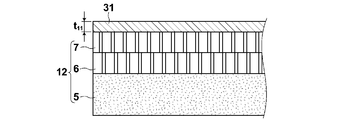
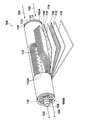
- a laminated film in which a hydrophilic porous film 7, a hydrophobic porous film 6, and an auxiliary supporting film 5 are laminated in this order is used as the support 12.
- hydrophilic porous membrane 7 polysulfone, cellulose membrane filter membrane, polyamide, polyimide interfacially polymerized thin film, polytetrafluoroethylene, high molecular weight polyethylene stretched porous membrane has a high porosity, and an acidic gas (especially carbon dioxide). ) Diffusion inhibition is small, which is preferable from the viewpoints of strength, manufacturability, and the like. Moreover, it is preferable to consist of a raw material which has heat resistance and little hydrolyzability. In particular, a stretched film of polytetrafluoroethylene (PTFE) is suitable. Moreover, you may obtain a hydrophilic porous membrane by hydrophilizing each porous membrane.
- PTFE polytetrafluoroethylene
- hydrophilic treatment method examples include plasma treatment, corona discharge treatment, UV treatment, and radiation treatment.
- hydrophobic porous membrane by coating the hydrophobic porous membrane with a hydrophilic resin, it may be hydrophilized as a core-sheath structure in which the hydrophobic porous membrane is the core and the hydrophilic resin is the sheath.
- the maximum hole diameter of the holes is preferably 1 ⁇ m or less.
- the average pore diameter of the pores of the porous support is preferably 0.001 ⁇ m or more and 10 ⁇ m or less, more preferably 0.002 ⁇ m or more and 5 ⁇ m or less, from the viewpoint of preventing the gas from passing through the region through which the gas passes. Furthermore, 0.005 ⁇ m or more and 1 ⁇ m or less is particularly preferable.
- hydrophobic porous membrane 6 examples include polysulfone, cellulose membrane filter membrane, polyamide, polyimide interfacially polymerized thin film, polytetrafluoroethylene, and high molecular weight polyethylene stretched porous membrane with high porosity and acidic gas (especially carbon dioxide). ) Diffusion inhibition is small, which is preferable from the viewpoint of strength, suitability for production, and the like. Moreover, it is preferable to consist of a raw material which has heat resistance and little hydrolyzability. In particular, a stretched film of polytetrafluoroethylene (PTFE) is suitable.
- PTFE polytetrafluoroethylene
- the hydrophobic porous membrane 6 has a function of preventing the facilitated transport membrane containing moisture from permeating from the hydrophilic porous membrane 7 side to the nonwoven fabric 5 side under the use environment, and includes the hydrophobic porous membrane 6. Thus, the film thickness distribution and the performance deterioration with time are not caused.
- the maximum hole diameter of the holes is preferably 1 ⁇ m or less.
- the average pore diameter of the pores of the porous membrane is 0.001 ⁇ m or more and 10 ⁇ m or less from the viewpoint that the adhesive application region is sufficiently impregnated with the adhesive and the gas passage region does not hinder gas passage. Is more preferable, 0.002 ⁇ m or more and 5 ⁇ m or less is more preferable, and 0.005 ⁇ m or more and 1 ⁇ m or less is particularly preferable.
- the maximum pore diameter means a value measured and calculated by the bubble point method.
- it can measure by the bubble point method (based on JISK3832) using the palm porometer made from PMI as a measuring apparatus.
- the auxiliary support membrane 5 is provided for reinforcing the porous membranes 6 and 7, and is not particularly limited as long as the strength, stretch resistance and gas permeability are good, and the nonwoven fabric, woven fabric, net, and A mesh having an average pore diameter of 0.001 ⁇ m or more and 10 ⁇ m can be appropriately selected and used.
- the auxiliary support membrane 5 is also preferably made of a material having heat resistance and low hydrolyzability, like the porous membrane 6 described above.
- Non-woven fabrics, woven fabrics, and knitted fabrics that have excellent durability and heat resistance include modified polyamides such as polypropylene and aramid (trade name), fluorine-containing resins such as polytetrafluoroethylene and polyvinylidene fluoride, etc.
- the fiber consisting of is preferred. It is preferable to use the same material as the resin material constituting the mesh. Of these materials, it is particularly preferable to use a nonwoven fabric made of polypropylene (PP) which is inexpensive and has high mechanical strength.
- PP polypropylene
- the mechanical strength can be improved, so that the support film does not wrinkle even when handled in a roll-to-roll coating device, and the productivity is increased. You can also.
- the support 12 is made of non-woven fabric made of hydrophilic PTFE as the hydrophilic porous membrane 7, PTFE as the hydrophobic porous membrane 6, and inexpensive and high mechanical strength polypropylene (PP) as the auxiliary support membrane 5. Particularly preferred.
- the hydrophilic porous membrane is a porous membrane in which at least the surface on the side on which the coating liquid for forming the facilitated transport film is applied is a hydrophilic surface.
- hydrophilic means that the contact angle of water at room temperature (25 ° C.) is 90 ° or less.
- the hydrophobic porous membrane is a porous membrane in which at least the surface in contact with the hydrophilic porous membrane is a hydrophobic surface.
- the hydrophilic porous film has a thickness of 3 to 100 ⁇ m
- the hydrophobic porous film has a thickness of about 5 to 100 ⁇ m
- the auxiliary support film has a thickness of about 50 to 300 ⁇ m.
- a coating liquid for forming an acidic gas separation layer containing a hydrophilic compound, an acidic gas carrier, and water is prepared.
- Preparation of the coating liquid is carried out by adding a hydrophilic polymer, which is a hydrophilic compound, and an acidic gas carrier, and, if necessary, other additives including a thickener and a crosslinking agent in water (room temperature water or warm water), respectively. It is added and stirred sufficiently, and if necessary, it is heated with stirring to promote dissolution.
- a hydrophilic polymer and an acidic gas carrier may be separately added to water, or those previously mixed may be added.
- the hydrophilic polymer and the thickener are added by gradually adding a hydrophilic polymer and an acidic gas carrier thereto and stirring. Precipitation (salting out) can be effectively prevented.
- the temperature of the coating solution is 15 ° C. or more and 35 ° C. or less, and at that temperature, the measured value at 60 rpm in the B-type viscometer is 0.5 Pa ⁇ s or more and 5 Pa ⁇ s or less.
- the viscosity of the coating solution before coating is preferably 0.5 Pa ⁇ s or more and 2 Pa ⁇ s or less (500 to 2000 cp) from the viewpoint of surface properties after coating and high speed, and is 1 Pa ⁇ s or more and 2 Pa ⁇ s or less (1000 -2000 cp) is more preferred.
- the viscosity at this time is a value at 60 rpm and a liquid temperature of 25 ° C. in a B-type viscometer.
- the viscosity is 0.5 Pa ⁇ s or more, the flow of the film after coating can be suppressed and the film thickness can be made uniform.
- the viscosity decreases, and when the temperature is low, the viscosity increases.
- the liquid temperature is 25 ° C. and the viscosity is within the above range, it is in a normal environment (about 10 to 35 ° C.) It means that it is suitable for the application of.
- the prepared coating solution for forming an acidic gas separation promoting transport film has a viscosity measurement value of 0.5 Pa ⁇ s or more at a rotation speed of 60 rpm in B-type viscosity measurement at any temperature within the range of 15 ° C. or more and 35 ° C. or less. Whether or not any viscosity in the range of 5 Pa ⁇ s or less can be confirmed can be confirmed as follows. That is, the prepared coating solution for forming an acidic gas separation promoting transport film is put into a stainless steel container (for example, 4 cm in inner diameter and 12 cm in height) so that the viscometer cylinder (rotor) is sufficiently immersed in the coating solution. .
- the stainless steel container is immersed in a temperature-adjustable water tank, and while adjusting the temperature of the applied coating solution in the range of 15 ° C. to 35 ° C., a B-type viscometer (BL2 1-100,000 mPa, manufactured by Techjam) S / KN3312481) is operated, the value for each temperature at a rotational speed of 60 rpm is read, and the viscosity of the coating solution is measured according to JIS Z8803.
- a B-type viscometer BL2 1-100,000 mPa, manufactured by Techjam
- the method for producing a composite for separating acidic gas according to the present invention comprises a roll-to-roll type coating machine using a belt-like (web-like) support for coating and drying the coating liquid. It is suitable for manufacture by.
- the method for applying the coating solution is not particularly limited as long as the coating solution having the above-described viscosity can be applied with the above-described thickness. Since the viscosity is high and the thickness is thick, post-weighing methods such as the roll coat method and blade coat method, in which a large amount of coating solution is transferred onto the support immediately before it is adjusted to the desired thickness by a later mechanism, are most suitable. ing.
- an extrusion coating method As other coating methods, an extrusion coating method, a dip coating method, a bar coating method, a curtain coating method, or the like may be employed. A plurality of coating methods may be combined. The roll coating method and the blade coating method are also preferable because they are inexpensive in terms of production equipment.
- the coating liquid for forming the prepared acid gas separation facilitated transport membrane as the liquid film thickness t 11 is 0.3mm or more 1.0mm or less It is applied to the surface of the hydrophilic porous membrane 6 of the porous support 12.
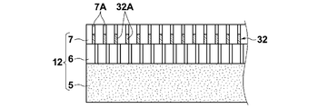
- the liquid 31 penetrates into the pores 7A of the hydrophilic porous membrane 7, and then dried to facilitate separation and transport of acidic gas to the individual pores 7A of the hydrophilic porous membrane 7 as shown in FIG. A film portion 32A is formed.
- the facilitated transport portion 32A formed in each hole 7A constitutes the facilitated transport film 32 as a whole.
- the facilitated transport film 32 is formed in the hydrophilic porous membrane 7, and the facilitated transport film 32 is not a continuous single film, but is formed from a number of facilitated transport portions 32A.
- a coating liquid is the above-mentioned viscosity, it does not osmose
- the coating liquid is replaced with air in the holes and permeates into the holes while discharging bubbles to the surface.
- the amount of liquid to be applied is too large, it takes time for the air to come out on the surface, so the liquid dries before the air is exhausted, and bubbles are generated in the acidic gas separation promoting transport section 32A.
- the facilitated transport portion 32A that is, the facilitated transport film 32
- the liquid film thickness at the time of application may be 1 mm or less, and there is no lower limit.
- the initial layer is made too thin, it is necessary to increase the number of subsequent layer formation steps in order to obtain a sufficient thickness.
- the liquid film thickness is 0.3 mm or more, it is preferable because a thick facilitated transport film can be obtained efficiently.
- the liquid film thickness at the time of coating is 0.3 mm or more and 0.7 mm from the viewpoint of the coating liquid sufficiently dipping into the hydrophilic porous film to make it free of bubbles and the production efficiency. It is preferable to set it as follows, and it is more preferable to set it as 0.3 mm or more and 0.6 mm or less.
- the liquid film thickness in the present specification basically means a set value on the coating apparatus (coating machine) side. Since the surface is applied to the porous film having a hydrophilic surface, the coating liquid soaks into the pores of the porous film immediately after coating, so that the liquid film thickness already set by the coating apparatus is not maintained immediately after coating.
- drying means removing at least a portion of water contained in the liquid film of the coating solution for forming an acidic gas separation promoting transport film formed on the support in the coating step.
- temperature of the drying furnace is appropriately determined in the range of 60 to 120 ° C. If it is 60 degreeC or more, drying time can be restrained to practical time.
- the high temperature side can be determined as appropriate mainly according to the heat resistance of the support, and is about 120 ° C. here.
- the temperature of the drying furnace is preferably 60 to 90 ° C., more preferably 70 to 80 ° C. from the stability of the film surface.
- various drying methods such as a drying method using warm air and a drying method using an infrared heater can be applied.
- the temperature in the drying furnace may not be uniform as long as it is 60 to 120 ° C.
- the temperature of the initial drying zone is preferably lower than that of the latter drying zone.
- the vicinity of the drying furnace inlet that is the initial drying zone is set to 60 ° C.
- the vicinity of the drying furnace center that is the intermediate drying zone is set to 70 ° C.
- the vicinity of the drying furnace outlet that is the latter drying zone is set to 90 ° C.
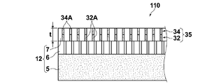
- next layer formation process As shown in FIG. 4, the surface of the hydrophilic porous membrane 7 provided with the acid gas separation promoting transport membrane 32 previously formed is applied to the coating solution for forming the acid gas separation promoting transport membrane. Apply to. Also at this time, the applied coating liquid 33 is soaked into the holes 7A of the hydrophilic porous membrane 7 and dried to form the tip of each hole 7A as shown in FIG. The acidic gas separation promoting and transporting portion 34A is formed on the acidic gas separation promoting and transporting portion 32A. The facilitated transport portion 34A formed in each hole 7A constitutes the facilitated transport film 34 as a whole.
- membrane 34 formed in the next layer formation process is the hydrophilic porous membrane 7. It may be configured by a facilitated transport portion 34A formed by penetrating into the pores 7A and a facilitated transport membrane 34B formed on the surface of the porous membrane 7.
- the next layer forming step is performed once or more after the initial layer forming step. It may be performed only once, or may be repeated twice or more. That is, the next layer forming step may be further repeated on the surface of the hydrophilic porous membrane 7 provided with the acidic gas separation promoting transport membrane 34 shown in FIG.
- the coating solution film thickness, the drying conditions, etc. may be the same or different. However, when it is necessary to wind up the support having the facilitated transport film formed on the take-up roll by the roll-to-roll method, in the next layer forming step, the coated surface usually comes into contact with the transport roll.
- the moisture content is as follows, assuming that the mass of a 10 cm square facilitated transport membrane in a dew point-20 ° C environment is A, and the mass of a 10 cm square facilitated transport membrane in a 25 ° C, 20% relative humidity environment is B. It is a value calculated by a calculation formula. (BA) ⁇ B ⁇ 100
- the acidic gas separation complex 110 shown in FIG. 5 or the acidic gas separation complex shown in FIG. 6 in which the acidic gas separation promoting transport film 35 is formed on the support 12 by one or more subsequent layer forming steps. 111 can be obtained.
- the thickness t of the acidic gas separation facilitating transport membrane 35 comprising a plurality of layers is preferably in the range of 40 ⁇ m to 100 ⁇ m in an environment of 25 ° C. and 30%.
- the thickness t 21 of the coating to the liquid film is preferable to be 3.0mm or less.
- the liquid film t 21 for applying a 3.0mm or less the occurrence of skin burr surface in the drying step is suppressed, it is possible to obtain a film having a smooth surface. Since the facilitated transport film having a sufficient thickness can be efficiently produced and a good film can be obtained, the thickness of the liquid film to be applied in the subsequent layer forming step should be 2.0 mm or more and 3.0 mm or less. preferable. In order to adjust the thickness, a thin liquid film layer of about 0.3 mm may be applied in the next layer forming step.
- the drying in the next layer forming step is the same as the initial layer forming step, but when applying a liquid film of more than 1.0 mm thicker than the initial layer in the next layer forming step, by performing rapid drying, Drying defects such as mottle and unevenness are likely to occur on the surface. Therefore, the drying in the next layer forming step is more preferably performed at a temperature lower than the temperature following the drying in the initial layer forming step.
- an acidic gas separation-enhanced transport membrane is formed by a plurality of coating and drying steps, so that a thicker acidic gas separation-enhanced transport membrane can be obtained. .
- the thick-film acidic gas separation promoting transport membrane By providing the thick-film acidic gas separation promoting transport membrane, the permeability of gases other than the predetermined acidic gas contained in the supply gas (raw gas) can be sufficiently lowered.
- Roll-to-Roll manufacturing equipment using a belt-like (web-like) support, with few membrane defects, and a composite for acidic gas separation with a thick acidic gas separation promoting transport membrane
- the body can be manufactured with high production efficiency and low production costs.
- the preparation step of the coating liquid for forming the acidic gas separation promoting transport film one type of coating liquid was prepared, and the same coating liquid was applied in a plurality of times.
- a plurality of forming coating solutions having different acid gas carrier concentrations are prepared, and in the next layer forming step, the previously formed acidic gas separation facilitated transport membrane is formed.
- the next-layer acidic gas separation facilitated transport film may be formed using a forming coating solution having a lower concentration of acidic gas carrier than the coating solution for use.
- metal carbonate is used as the acidic gas carrier, the acidic gas separation facilitating transport membrane contains a large amount of metal carbonate in the membrane.
- the carrier concentration of the film formed on the uppermost layer is lowered so that the deposition of the carrier accelerator on the surface can be delayed in time.
- a plurality of forming coating liquids having different hydrophilic compounds are prepared as the coating liquid for forming the acidic gas separation promoting transport film, and the acidic gas separation previously formed in the next layer forming process is prepared.
- the hydrophilic compound of the coating solution for forming the first acidic gas separation promoting transport membrane is a polyvinyl alcohol-polyacrylic acid copolymer
- the copolymer is used as the coating solution for forming the acidic gas separation promoting transport membrane of the next layer.
- Hydrophilic compounds containing polyvinyl alcohol-polyacrylic acid copolymers having different ratios may be used.
- a coating solution for forming with different addition amounts of thickeners, additives and the like is further prepared, and the first acidic gas separation-enhanced transport membrane is prepared.
- Different forming coating liquids may be used at the time of formation and at the time of forming the acidic gas separation promoting transport film of the next layer.
- a plurality of coating solutions for forming different concentrations of acid gas carrier concentration, hydrophilic compound concentration, and thickening agent or additive concentration are prepared, and the first acid gas separation promoting transport membrane is prepared.
- Different forming coating liquids may be used at the time of formation and at the time of forming the acidic gas separation promoting transport film of the next layer.
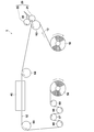
- FIG. 7 schematically shows an example of an apparatus configuration used in the production process of the acidic gas separation composite according to the present invention.
- the apparatus 100 is provided with a feed roll 10 that feeds a belt-like support 12 and a coater 20 that applies a coating solution 30 for forming an acidic gas separation layer on the support 12 (in FIG. 7, in the direction of the arrow in the figure).
- a drying unit including a drying furnace 40 for drying a membrane (not shown) and a winding process unit 5 including a winding roll 50 that winds up the obtained acidic gas separating composite 52 are provided. Further, transport rolls 62 (also functioning as backup rolls for the roll coater in FIG. 1) and 64 to 69 for transporting the support 12 to the respective parts 20, 40, 50 are arranged.
- a roll-to-roll that is, a support 12 is sent out from the feed roll 10 and the coating process is performed while the support 12 is conveyed, and The drying process is sequentially performed, and the support body 52 on which the facilitated transport film is formed can be wound on the take-up roll 50, and the facilitated transport film can be continuously and efficiently formed.
- the transport speed of the support 12 depends on the type of the support 12 and the viscosity of the composition (coating liquid), but if the transport speed of the support is too high, the film thickness uniformity of the coating film in the coating process is reduced. If it is too late, productivity will decrease.
- the conveyance speed of the support 12 may be determined according to the type of the support 12 and the viscosity of the composition in consideration of the above points, but is preferably 1 m / min or more, and more preferably 5 m / min or more and 100 m / min. The following is more preferable.
- the initial layer forming step and the next layer forming step are performed by forming an initial layer forming step in the manufacturing apparatus 1 as shown in FIG.
- the method of performing the process is the simplest.
- the next layer may be formed without winding after the initial layer is formed using a coating machine provided with a plurality of coating units and drying ovens.
- the belt-like support 12 is fed from the feed roll 10 and conveyed to the coater 20 of the coating unit, and the coating solution is at a temperature of 15 ° C. or more and 35 ° C. or less, and the B-type viscosity measurement is performed at 60 rpm.
- a viscosity measured value is applied on the support 12 with a viscosity of 0.5 Pa ⁇ s or more and 5.0 Pa ⁇ s or less, and a liquid film of the coating solution is provided on the support 12.
- the hydrophilic polymer may precipitate (salt out) and it may be difficult to apply to the support or the film thickness may vary greatly.
- a roll coater or a blade coater is particularly preferable.
- the roll coater combines one or more rolls to control the amount of coating liquid held on the surface of the roll (applicator roll) arranged closest to the support, and the coating liquid on the (applicator roll) Is a coater that transfers a certain amount of the above to the support surface.
- Suitable roll coaters include a direct gravure coater, an offset gravure coater, a single roll kiss coater, a three reverse roll coater, a forward rotation roll coater and the like.
- a three reverse roll coater suitable for application of a coating solution having a medium viscosity to a high viscosity of 5 Pa ⁇ s to 5.0 Pa ⁇ s is preferred.
- the blade coater is a coater that, after applying an excessive amount of coating solution on a support, scrapes off the excess amount of the coating solution on the support with a blade.
- the drying furnace 40 of the manufacturing apparatus At least a part of water as a solvent contained in the coating film of the coating solution for forming a carbon dioxide separation layer formed on the support in the coating process is removed.
- a drying step is performed by heating the support on which the coating film is held, blowing dry air on the coating film, or both.
- the temperature is more preferably 60 ° C. or higher and 90 ° C. or lower, and further preferably 70 ° C. or higher and 80 ° C. or lower.
- the rolls 67 and 69 are in contact with the formed facilitated transport film surface. It is necessary to dry the facilitated transport film to such an extent that the roll is not contaminated and the surface of the facilitated transport film is not defective. In the roll-to-roll system, the transport roll must be in contact with the coating surface to absorb the feeding and winding speed (peripheral speed) and adjust the tension. It is.
- the coating step is performed by applying the coating solution for forming an acidic gas separation promoting transport film to a range of 15 ° C. to 35 ° C.
- the viscosity measured at a rotation speed of 60 rpm in the range of 15 ° C. to 35 ° C. is 1 Pa ⁇ It is applied on the support with a viscosity of s to 5.0 Pa ⁇ s.
- hydrophilic polymer is mentioned as a hydrophilic compound contained in a coating liquid.
- the hydrophilic polymer functions as a binder, holds water in the acidic gas separation promoting transport membrane, and exhibits the acidic gas separating function by the acidic gas carrier.
- the acidic gas separation facilitating transport membrane preferably has high water absorption (retention property)
- the hydrophilic polymer preferably has high water absorption
- the physiological saline has a water absorption of 0.5 g / g or more.
- it has water absorption, more preferably 1 g / g or more, more preferably 5 g / g or more, and more preferably 10 g / g or more. It is particularly preferable that it has a water absorption of 20 g / g or more.
- hydrophilic polymer contained in the coating solution a conventionally known hydrophilic polymer can be used.
- a conventionally known hydrophilic polymer can be used.
- these copolymers are also preferred, and these copolymers can also be preferably used.
- polyvinyl alcohol-polyacrylate copolymer particularly preferred is a polyvinyl alcohol-polyacrylate copolymer.
- the polyvinyl alcohol-polyacrylate copolymer has a high water absorption capacity and also has a high hydrogel strength even at high water absorption.
- the content of polyacrylate in the polyvinyl alcohol-polyacrylate copolymer is, for example, 1 to 95 mol%, preferably 2 to 70 mol%, more preferably 3 to 60 mol%, and particularly preferably 5 to 50 mol%. Mol%.
- polyacrylic acid salts include alkali metal salts such as sodium salt and potassium salt, as well as ammonium salts and organic ammonium salts.
- polyvinyl alcohol-polyacrylate copolymer sodium salt
- Crustomer AP20 trade name: manufactured by Kuraray Co., Ltd.
- Two or more hydrophilic polymers may be mixed and used.
- the content of the hydrophilic polymer in the coating liquid depends on the type, but from the viewpoint of forming a membrane as a binder and allowing the acidic gas separation promoting transport membrane to sufficiently retain moisture, 0.5% by mass
- the content is preferably 50% by mass or less, more preferably 1% by mass or more and 30% by mass or less, and particularly preferably 2% by mass or more and 15% by mass or less.
- the acid gas carrier means one that indirectly reacts with the acid gas or one that itself reacts directly with the acid gas.
- the acid gas carrier various water-soluble inorganic and organic substances showing basicity are used. Examples of the substance that reacts indirectly with the acid gas include those that react with other gases contained in the supply gas, show basicity, and react with the basic compound and the acid gas. More specifically react with steam OH - to the release, the OH - refers to alkali metal compounds can be incorporated selectively CO 2 in the film by reacting with CO 2 . Examples of those that react directly with acid gas include basic compounds such as nitrogen-containing compounds and sulfur oxides.
- alkali metal compound examples include at least one selected from alkali metal carbonates, alkali metal bicarbonates, or alkali metal hydroxides.
- alkali metal an alkali metal element selected from cesium, rubidium, potassium, lithium, and sodium is preferably used.
- an alkali metal compound is used in the meaning containing the salt and its ion other than alkali metal itself.
- Examples of the alkali metal carbonate include lithium carbonate, sodium carbonate, potassium carbonate, rubidium carbonate, and cesium carbonate.
- Examples of the alkali metal bicarbonate include lithium hydrogen carbonate, sodium hydrogen carbonate, potassium hydrogen carbonate, rubidium hydrogen carbonate, and cesium hydrogen carbonate.
- Examples of the alkali metal hydroxide include lithium hydroxide, sodium hydroxide, potassium hydroxide, cesium hydroxide, and rubidium hydroxide. Among these, alkali metal carbonates are preferable, and compounds containing cesium, rubidium, and potassium having high solubility in water are preferable. Moreover, you may mix and use 2 or more types of acidic gas carriers. For example, what mixed cesium carbonate and potassium carbonate can be mentioned suitably.
- nitrogen-containing compounds include amino acids such as glycine, alanine, serine, proline, histidine, taurine, and diaminopropionic acid, hetero compounds such as pyridine, histidine, piperazine, imidazole, and triazine, monoethanolamine, diethanolamine, and triazine.
- Alkanolamines such as ethanolamine, monopropanolamine, dipropanolamine, tripropanolamine, cyclic polyetheramines such as cryptand [2.1] and cryptand [2.2], cryptand [2.2.1] Bicyclic polyetheramines such as cryptand [2.2.2], porphyrin, phthalocyanine, ethylenediaminetetraacetic acid and the like can be used.
- amino acids such as cystine and cysteine, polythiophene, dodecylthiol and the like can be used.
- the content of the acidic gas carrier in the coating liquid is 0.3 to 30% by mass in order to prevent salting out before coating and to ensure the separation function of acidic gas, depending on the type. It is preferably 0.5 to 25% by mass, more preferably 1 to 20% by mass.
- the coating solution preferably contains a hydrophilic polymer and an acidic gas carrier in a mass ratio of 1: 9 to 2: 3. More preferably, it is in the range of 1: 4 or more and 2: 3 or less, more preferably 3: 7 or more and 2: 3 or less.
- Thickener Coating liquid composition for forming an acidic gas separation promoting transport film, comprising a hydrophilic polymer, an acidic gas carrier, and water, wherein the mass ratio of the hydrophilic polymer to the acidic gas carrier is from 1: 9 to 2: 3.
- a thickener may be further used in the coating solution composition.
- any compound may be used as long as it can increase the viscosity of the coating liquid composition within a temperature range of 15 ° C. or more and 35 ° C. or less.
- Carboxymethyl cellulose that can be suitably used has a degree of etherification in the range of 0.6 to 1.5, and a viscosity measurement value at a rotation speed of 60 rpm in a B-type viscosity measurement when the aqueous solution is 1% by mass is 1 Pa ⁇ It is in the range of s to 10 Pa ⁇ s.
- carboxymethylcellulose When such carboxymethylcellulose is used, a coating liquid composition for forming an acidic gas separation promoting transport film having a desired viscosity can be easily obtained with a small amount of content, and at least components other than the solvent contained in the coating liquid can be obtained. There is also little risk that a part of the coating solution cannot be dissolved and deposited.
- carboxymethylcellulose can be obtained from commercial products, and preferred examples include CMC2280 manufactured by Daicel Finechem Co., Ltd.
- the content of the thickener in the composition (coating liquid) is 0.5 Pa ⁇ s at a rotation speed of 60 rpm in the B-type viscosity measurement at any temperature within the range of 15 ° C. to 35 ° C. As long as it can be adjusted so as to exhibit any viscosity within the range of 5.0 Pa ⁇ s or less, it is preferably as small as possible. As a general index, it is preferably 10% by mass or less, more preferably 0.1% by mass or more and 5% by mass or less, and most preferably 0.1% by mass or more and 2% by mass or less.
- the hydrophilic polymer can be crosslinked by a conventionally known method such as thermal crosslinking, ultraviolet crosslinking, electron beam crosslinking, or radiation crosslinking. It is preferable that the composition of this invention contains a crosslinking agent. In particular, it preferably contains a cross-linking agent having two or more functional groups capable of reacting with the polyvinyl alcohol-polyacrylate copolymer and thermally cross-linking, and includes polyvalent glycidyl ether, polyhydric alcohol, polyvalent isocyanate, polyvalent aziridine, Examples include haloepoxy compounds, polyhydric aldehydes, polyhydric amines, and the like.
- polyvalent glycidyl ether for example, ethylene glycol diglycidyl ether, polyethylene glycol diglycidyl ether, glycerol polyglycidyl ether, diglycerol polyglycidyl ether, polyglycerol polyglycidyl ether, sorbitol polyglycidyl ether, pentaerythritol poly Examples thereof include glycidyl ether, propylene glycol glycidyl ether, and polypropylene glycol diglycidyl ether.
- polyhydric alcohol examples include ethylene glycol, diethylene glycol, triethylene glycol, tetraethylene glycol, polyethylene glycol glycerin, polyglycerin, propylene glycol, diethanolamine, triethanolamine, polyoxypropyl, and oxyethylene oxypropylene block. Copolymers, pentaerythritol, sobitol and the like can be mentioned.
- examples of the polyvalent isocyanate include 2,4-toluylene diisocyanate and hexamethylene diisocyanate.
- examples of the polyvalent aziridine include 2,2-bishydroxymethylbutanol-tris [3- (1-acylidinyl) propionate], 1,6-hexamethylenediethyleneurea, diphenylmethane-bis-4,4′- N, N′-diethylene urea and the like can be mentioned.
- Examples of the haloepoxy compound include epichlorohydrin and ⁇ -methylchlorohydrin.
- Examples of the polyvalent aldehyde include glutaraldehyde and glyoxal.
- Examples of the polyvalent amine include ethylenediamine, diethylenetriamine, triethylenetetramine, tetraethylenepentamine, pentaethylenehexamine, and polyethyleneimine.
- glutaraldehyde is particularly preferred as the thermal crosslinking agent for the polyvinyl alcohol-polyacrylate copolymer.
- the coating liquid can contain one or more other components (additives) other than the hydrophilic polymer, the acidic gas carrier, and the thickener as long as the coating properties and gas separation characteristics are not adversely affected.
- other components include, in addition to the above-described crosslinking agent, for example, surfactants, catalysts, moisturizing (water absorbing) agents, auxiliary solvents, film strength adjusting agents, and defect detecting agents.
- crosslinking agent for example, surfactants, catalysts, moisturizing (water absorbing) agents, auxiliary solvents, film strength adjusting agents, and defect detecting agents.
- FIG. 8 is a schematic configuration diagram showing a spiral type acidic gas separation module 100 according to the first embodiment of the acidic gas separation module of the present invention, in which a notch is provided.
- the acidic gas separation module 100 has a basic structure in which the outermost periphery of the laminate 114 is wound around a permeate gas collecting pipe 112 in a state where one or more laminates 114 described later are wound. Covered with a covering layer 116, telescope prevention plates 118 are attached to both ends of these units.
- the module 100 having such a configuration when the source gas 120 containing an acidic gas is supplied to the laminate 114 from the one end 100A side, the source gas 120 is mixed with the acid gas 122 and the remaining gas by the configuration of the laminate 114. It is separated into 124 and discharged separately to the other end 100B side.
- the permeate gas collecting pipe 112 is a cylindrical pipe having a plurality of through holes 112A formed in the pipe wall.
- the one end side (one end 100A side) of the permeate gas collecting pipe 112 is closed, and the other end side (the other end 100B side) of the permeate gas collecting pipe 112 is opened and penetrates the laminate to collect from the through hole 112A.
- a discharge port 126 from which acidic gas 122 such as gas is discharged is provided.
- the shape of the through hole 112A is not particularly limited, but it is preferable that a circular hole with a diameter of 1 to 20 mm ⁇ is opened. Further, it is preferable that the through holes 112A are arranged uniformly with respect to the surface of the permeate gas collecting pipe 112.
- the coating layer 116 is formed of a blocking material that can block the source gas 120 that passes through the acidic gas separation module 100.
- This blocking material preferably further has heat and humidity resistance.
- heat resistance in the heat and humidity resistance means having a heat resistance of 80 ° C. or higher.
- the heat resistance of 80 ° C. or higher means that the shape before storage is maintained even after being stored for 2 hours under a temperature condition of 80 ° C. or higher, and curling that can be visually confirmed by heat shrinkage or heat melting does not occur.
- “moisture resistance” of the heat and humidity resistance is a curl that can be visually confirmed by heat shrinkage or heat melting even after being stored at 40 ° C. and 80% RH for 2 hours. It means not occurring.
- the telescope prevention plate 118 is preferably made of a heat and moisture resistant material.
- the laminated body 114 is formed by laminating a permeating gas flow path member 135, an acidic gas separation complex 110, a supply gas flow path member 130, and an acidic gas separation complex 110. It is wound around the permeating gas collecting pipe 112.
- the source gas 120 containing the acid gas 122 is supplied from the end of the supply gas flow path member 130 and permeates the acid gas separation complex 110 partitioned by the coating layer 116 for separation.
- the acid gas 122 is accumulated in the permeate gas collecting pipe 112 via the permeate gas flow path member 135 and the through hole 112A, and is collected from the discharge port 126 connected to the permeate gas collective pipe 112. Further, the residual gas 124 from which the acidic gas 122 has been separated that has passed through the gap of the supply gas flow path member 130 is discharged from the end of the acidic gas separating complex 110.
- the acidic gas separation complex 110 is manufactured by the manufacturing method of the present invention, and includes a porous support, a porous structure in which a hydrophilic porous membrane, a hydrophobic porous membrane, and an auxiliary support membrane are laminated in this order. And an acidic gas separation facilitating transport membrane containing an acidic gas carrier that generates an acidic gas carrier that reacts with the acidic gas in the raw material gas and at least the hydrophilic polymer supported by the hydrophilic porous body of the porous support.
- the number of the laminated body 114 wound around the permeate gas collecting pipe 112 is not particularly limited, and may be single or plural. By increasing the number (number of laminated layers), the membrane area of the facilitated transport film can be improved. Thereby, the quantity which can isolate
- the supply gas flow path member 130 is a member to which a source gas containing an acid gas is supplied from one end of the acid gas separation module, has a function as a spacer, and causes a turbulent flow in the source gas. Therefore, a net-like member is preferably used. Since the gas flow path changes depending on the shape of the net, the shape of the unit cell of the net is selected from shapes such as rhombus and parallelogram according to the purpose. Assuming that a raw material gas containing water vapor is supplied at a high temperature, the supply gas flow path member preferably has moisture and heat resistance in the same manner as the acidic gas separation layer described later.
- the material of the supply gas flow path member 130 is not limited in any way, but paper, fine paper, coated paper, cast coated paper, synthetic paper, cellulose, polyester, polyolefin, polyamide, polyimide, polysulfone, aramid, Examples thereof include resin materials such as polycarbonate and inorganic materials such as metal, glass and ceramics.
- the resin materials include polyethylene, polystyrene, polyethylene terephthalate, polytetrafluoroethylene (PTFE), polyethersulfone (PES), polyphenylene sulfide (PPS), polysulfone (PSF), polypropylene (PP), polyimide, polyetherimide, poly Suitable examples include ether ether ketone and polyvinylidene fluoride.
- preferable materials from the viewpoint of heat and humidity resistance include inorganic materials such as ceramics, glass, and metals, organic resin materials having heat resistance of 100 ° C. or higher, high molecular weight polyester, polyolefin, heat resistant polyamide, polyimide, and the like.
- Polysulfone, aramid, polycarbonate, metal, glass, ceramics and the like can be suitably used. More specifically, at least one selected from the group consisting of ceramics, polytetrafluoroethylene, polyvinylidene fluoride, polyethersulfone, polyphenylene sulfide, polysulfone, polyimide, polypropylene, polyetherimide, and polyetheretherketone. It is preferable that it is comprised including these materials.
- the thickness of the supply gas flow path member is not particularly limited, but is preferably 100 ⁇ m or more and 1000 ⁇ m or less, more preferably 150 ⁇ m or more and 950 ⁇ m or less, and further preferably 200 ⁇ m or more and 900 ⁇ m or less.
- the permeating gas channel member 135 is a member that reacts with the carrier and passes through the acidic gas separating complex 110 and the acidic gas flows toward the through hole.
- the permeate gas flow path member 135 has a function as a spacer, and also has a function of causing the permeated acidic gas to flow inside the permeate gas flow path member 135.
- An example is a tricot knitting shape.
- the material of the permeating gas flow path member can be the same as that of the supply gas flow path member.
- the permeate gas channel member has moisture and heat resistance in the same manner as the acidic gas separation layer.
- polyesters such as epoxy-impregnated polyester, polyolefins such as polypropylene, and fluorines such as polytetrafluoroethylene.
- the thickness of the permeating gas channel member is not particularly limited, but is preferably 100 ⁇ m or more and 1000 ⁇ m or less, more preferably 150 ⁇ m or more and 950 ⁇ m or less, and further preferably 200 ⁇ m or more and 900 ⁇ m or less.
- the complex for acid gas separation produced by the production method of the present invention may be installed as a flat membrane, a spiral type known as a reverse osmosis membrane module, for example, JP 2010-279885 A, etc. It can also be used after being processed into a pleated mold having a shape as described in 1. Furthermore, the acidic gas separation module according to the present invention can be used by being set in an acidic gas separation device.
- the initial layer forming step and the next layer forming step were sequentially performed using a roll-to-roll coating machine provided with a coating unit and a drying unit.
- the next layer forming step is performed once.
- As the coating method a blade coating method was selected, and coating with a desired liquid film thickness was performed by adjusting the blade height. At this time, the width of the porous support was 500 mm, and the coating width was 470 mm.
- Example 1 As the initial layer forming step, the blade height is adjusted and the first layer (initial layer) is applied with a liquid film thickness of 0.3 mm, then dried in the drying furnace, and the hydrophilic porous membrane is filled with carbon dioxide. A carbon separation facilitated transport membrane was formed. After winding up the support, it was placed again in the delivery section. As the next layer forming step, the blade height was adjusted, and the coating liquid was applied onto the carbon dioxide separation layer so that the liquid film became 2.0 mm, and then dried in the same manner as in the initial layer formation.
- Example 2 The blade height was adjusted so that the liquid film thickness of the first layer in Example 1 was 1.0 mm, and the liquid film thickness of the second layer (next layer) was 1.0 mm, and coating and drying were performed. A composite for carbon dioxide separation was obtained.
- Example 3 The blade height was adjusted so that the liquid film thickness of the first layer in Example 1 was 1.0 mm, and the liquid film thickness of the second layer (next layer) was 3.0 mm, and coating and drying were performed. A composite for carbon dioxide separation was obtained.
- Example 1 (Comparative Example 1) The blade height was adjusted so that the liquid film thickness of the first layer in Example 1 was 3.0 mm, and coating and drying were performed to obtain a composite for carbon dioxide separation. Here, the next layer was not formed, and only one coating / drying step was performed.
- Example 2 The blade height was adjusted so that the liquid film thickness of the first layer in Example 1 was 2.0 mm, and the liquid film thickness of the second layer (next layer) was 2.0 mm, and coating and drying were performed. A composite for carbon dioxide separation was obtained.
- Example 1 both evaluations were good and the production method was good (A).
- Example 3 the roll was slightly contaminated when the second layer was applied. However, since a sufficiently usable composite was obtained, it was judged as possible (B). On the other hand, in Comparative Example 1, many bubbles were mixed. In Comparative Example 2, unevenness and irregularities were observed on the film surface after coating and drying of the second layer, and there were roll stains. C).
Abstract
[Problem] To obtain a complex for separating oxidizing gas, provided with a thick-film transport film for promoting oxidizing gas separation [Solution] A coating solution for forming a transport film for promoting oxidizing gas separation containing a hydrophilic compound, an acidic gas carrier and water is prepared; using a laminar film obtained by laminating hydrophilic porous film (7), a hydrophobic porous film (6) and a non-woven fabric (5) in this order as a porous support (12), a coating solution is applied to the surface of the hydrophilic porous film (7) of the laminated film at a liquid film thickness of 0.3mm to 1.0mm; the applied solution (31) is dried to form the initial transport film for promoting oxidizing gas separation (32); the coating solution for forming a transport film for promoting oxidizing gas separation is further applied to the surface of the hydrophilic porous film (7) provided with the pre-formed transport film for promoting oxidizing gas separation (32), and the solution (33) applied is dried to form the subsequent transport film for promoting oxidizing gas separation (34).
Description
本発明は、酸性ガス分離機能を有する酸性ガス分離用複合体の製造方法に関するものである。
The present invention relates to a method for producing a complex for acidic gas separation having an acidic gas separation function.
近年、混合ガス中の酸性ガスを選択的に分離する技術の開発が進んでいる。特には、二酸化炭素を選択的に分離する技術の開発が進んでいる。例えば、地球温暖化対策として排ガス中の二酸化炭素を回収して濃縮する技術や、水蒸気改質により炭化水素を水素と一酸化炭素(CO)に改質し、さらに一酸化炭素と水蒸気を反応させて二酸化炭素と水素を生成させ、二酸化炭素を選択的に透過する膜によって二酸化炭素を排除することで水素を主成分とする燃料電池用等のガスを得る技術が開発されている。
In recent years, the development of technology for selectively separating acidic gas in a mixed gas has progressed. In particular, development of a technique for selectively separating carbon dioxide is in progress. For example, as a global warming countermeasure, carbon dioxide in exhaust gas is collected and concentrated, or by steam reforming, hydrocarbons are reformed to hydrogen and carbon monoxide (CO), and carbon monoxide and steam are reacted. In order to produce carbon dioxide and hydrogen, a technology for obtaining a gas for fuel cells, etc., mainly containing hydrogen by eliminating carbon dioxide with a membrane that selectively permeates carbon dioxide has been developed.
このような酸性ガスを選択的に透過させて分離する酸性ガス分離膜として、膜中に含有されている酸性ガスキャリアによって、酸性ガスを膜の原ガス供給側から反対側に輸送し、酸性ガスの分離を行う促進輸送膜が知られている。
As an acid gas separation membrane that selectively permeates and separates such acid gas, the acid gas is transported from the raw gas supply side to the opposite side of the membrane by the acid gas carrier contained in the membrane. Facilitated transport membranes that perform separation of these are known.
例えば、特許文献1には、未架橋のビニルアルコール-アクリル酸塩共重合体水溶液を二酸化炭素透過性支持体上へ膜状に塗布して、当該支持体上に未架橋のビニルアルコール-アクリル酸塩共重合体水溶液の液膜を形成した後、この液膜を加熱して架橋させることにより水不溶化膜とし、この水不溶化膜に、二酸化炭素キャリア(二酸化炭素と親和性を有する物質)を含む水溶液を吸収させてハイドロゲル膜として、このハイドロゲル膜からなる促進輸送膜を支持体に担持させてなる二酸化炭素分離用複合体の製造方法が記載されている。
For example, Patent Document 1 discloses that an uncrosslinked vinyl alcohol-acrylate copolymer aqueous solution is applied in a film form onto a carbon dioxide permeable support, and the uncrosslinked vinyl alcohol-acrylic acid is applied onto the support. After forming a liquid film of the salt copolymer aqueous solution, the liquid film is heated and cross-linked to form a water-insoluble film, and the water-insoluble film contains a carbon dioxide carrier (a substance having an affinity for carbon dioxide). A method for producing a composite for carbon dioxide separation in which an aqueous solution is absorbed to form a hydrogel membrane and a facilitated transport membrane made of this hydrogel membrane is supported on a support is described.
特許文献2には、ポリビニルアルコール-ポリアクリル酸共重合体およびアルカリ金属炭酸塩を含む塗布液に寒天などのゲル化剤を添加し、50℃以上で調製した塗布液を支持体上に塗布した後、液膜を冷却させてゲル化させた後に、乾燥させることにより促進輸送膜を支持体に担持させてなる二酸化炭素分離用複合体の製造方法が記載されている。
In Patent Document 2, a gelling agent such as agar is added to a coating solution containing a polyvinyl alcohol-polyacrylic acid copolymer and an alkali metal carbonate, and a coating solution prepared at 50 ° C. or more is coated on a support. Thereafter, a method for producing a composite for carbon dioxide separation in which a liquid membrane is cooled and gelled and then dried and dried by supporting the facilitated transport membrane on a support is described.
特許文献3には、親水性の多孔質膜と疎水性の多孔質膜とを積層させた積層膜に、促進輸送膜形成用の塗布液を塗布して、多孔質膜の一部に塗布液が浸透して形成されたガス分離膜を備えた酸性ガス分離用複合体の製造方法が開示されている。
In Patent Document 3, a coating liquid for forming a facilitated transport film is applied to a laminated film obtained by laminating a hydrophilic porous film and a hydrophobic porous film, and the coating liquid is applied to a part of the porous film. A method for producing a complex for acidic gas separation provided with a gas separation membrane formed by permeation of water is disclosed.
特許文献1では、ゲル膜の厚さ1~200μm程度が想定されており、特許文献2は液膜厚み1mm以下で塗布してゲル化乾燥させて5~50μm程度の厚みの促進輸送膜を形成することが想定されている。また、特許文献3では、分離活性層(促進輸送膜)の膜厚として0.01~200μmが想定されている。
In Patent Document 1, it is assumed that the gel film has a thickness of about 1 to 200 μm, and in Patent Document 2, it is applied at a liquid film thickness of 1 mm or less and gelled and dried to form a facilitated transport film having a thickness of about 5 to 50 μm. It is assumed that In Patent Document 3, it is assumed that the thickness of the separation active layer (facilitated transport membrane) is 0.01 to 200 μm.
ところで、例えば二酸化炭素と水素の混合ガスから二酸化炭素を分離する場合、二酸化炭素分離用の促進輸送膜は化学反応により二酸化炭素を積極的に透過させるものであるが、水素は膜表面に溶解~拡散して透過する。そのため、水素の透過性を下げるという観点では、促進輸送膜の厚みが厚ければ厚いほどよい。また、支持体上に上記のようなゲル膜を塗布/乾燥により形成する製造方法の場合、膜厚が薄いと支持体表面の異物に敏感となり、ゲル膜にピンホール等の欠陥が生じる恐れがある。
By the way, for example, when carbon dioxide is separated from a mixed gas of carbon dioxide and hydrogen, the facilitated transport membrane for carbon dioxide separation actively permeates carbon dioxide through a chemical reaction, but hydrogen dissolves on the membrane surface. Diffuse and transmit. Therefore, from the viewpoint of reducing the hydrogen permeability, the thicker the facilitated transport film, the better. In addition, in the case of the production method in which the gel film as described above is formed on the support by coating / drying, if the film thickness is thin, the gel film is sensitive to foreign matters on the surface of the support, which may cause defects such as pinholes in the gel film. is there.
これらの事情から、特許文献1~3の場合よりも厚みの厚い促進輸送膜に対する要請がある。しかしながら、支持体への液膜塗布時に液膜を単に厚く塗った場合、例えば3mm超えとなるほど厚い液膜を塗布して乾燥させる場合には、膜表面側と支持体側の乾燥過程が大きく異なるため、膜表面がウロコ状の凹凸発生や、キャリアやポリマーの偏在が起こることが本発明者らの検討により明らかになった。また厚い液膜を乾燥させるためには、製造プロセス上も乾燥炉が非常に長い設計の塗布機が必要となり、新規設備導入が必要となるという問題もある。
For these reasons, there is a demand for a facilitated transport film that is thicker than those of Patent Documents 1 to 3. However, when the liquid film is simply applied thickly when applying the liquid film to the support, for example, when a liquid film thicker than 3 mm is applied and dried, the drying process on the film surface side and the support side is greatly different. As a result of studies by the present inventors, it has been found that the film surface has irregularities on the surface and uneven distribution of carriers and polymers. In addition, in order to dry a thick liquid film, a coating machine with a very long drying furnace is necessary in the manufacturing process, and there is a problem that new equipment must be introduced.
本発明は、上記課題に鑑みてなされたものであり、厚膜の酸性ガス分離促進輸送膜を備えた酸性ガス分離用複合体の製造方法を提供することを目的とする。
The present invention has been made in view of the above-described problems, and an object of the present invention is to provide a method for producing a complex for acidic gas separation having a thick acidic gas separation promoting transport membrane.
本発明の酸性ガス分離用複合体の製造方法は、多孔質支持体上に原料ガス中の酸性ガスを分離する機能を有する酸性ガス分離促進輸送膜を備えてなる酸性ガス分離用複合体の製造方法であって、
親水性化合物、酸性ガスキャリアおよび水を含む、酸性ガス促進輸送膜の形成用塗布液を調製する塗布液調製工程と、
多孔質支持体として親水性多孔質膜、疎水性多孔質膜および不織布がこの順に積層されてなる積層膜を用い、積層膜の親水性多孔質膜の表面に、形成用塗布液を液膜厚さ0.3mm以上1.0mm以下で塗布し、塗布された液膜を乾燥させて最初の酸性ガス分離促進輸送膜を形成する初期層形成工程と、
先に形成された前記酸性ガス分離促進輸送膜を備えた親水性多孔質膜の表面に、酸性ガス分離促進輸送膜の形成用塗布液をさらに塗布し、塗布された液膜を乾燥させて次の酸性ガス分離促進輸送膜を形成する1回以上の次層形成工程とを含む。 The method for producing a complex for acidic gas separation according to the present invention is a method for producing a complex for acidic gas separation comprising an acidic gas separation promoting transport membrane having a function of separating acidic gas in a raw material gas on a porous support. A method,
A coating liquid preparation step for preparing a coating liquid for forming an acidic gas facilitated transport film, comprising a hydrophilic compound, an acidic gas carrier and water;
As the porous support, a laminated film in which a hydrophilic porous film, a hydrophobic porous film, and a nonwoven fabric are laminated in this order is used, and the forming coating solution is applied to the surface of the hydrophilic porous film of the laminated film. An initial layer forming step of applying a thickness of 0.3 mm to 1.0 mm, and drying the applied liquid film to form an initial acidic gas separation promoting transport film;
A coating liquid for forming an acidic gas separation promoting transport film is further applied to the surface of the hydrophilic porous membrane having the acidic gas separation promoting transport film formed previously, and the applied liquid film is dried and then applied. One or more next layer forming steps for forming the acidic gas separation promoting transport membrane.
酸性ガス促進輸送膜の形成用塗布液が、15℃以上35℃以下の温度、かつB型粘度測定において回転数60rpmにおける粘度測定値が0.5Pa・s以上5Pa・s以下であることが好ましい。
It is preferable that the coating solution for forming the acidic gas facilitated transport film has a viscosity measurement value of 0.5 Pa · s or more and 5 Pa · s or less at a temperature of 15 ° C. or more and 35 ° C. or less and a B-type viscosity measurement at a rotation speed of 60 rpm. .
次層形成工程においては、酸性ガス促進輸送膜の形成用塗布液を液膜厚さ3.0mm以下で塗布することが好ましい。
In the next layer forming step, it is preferable to apply the coating liquid for forming the acidic gas facilitated transport film with a film thickness of 3.0 mm or less.
塗布法としては、ロールコート法またブレードコート法が好適である。
As the coating method, a roll coating method or a blade coating method is suitable.
親水性化合物が、ポリビニルアルコール-ポリアクリル酸共重合体であることが好ましい。
It is preferable that the hydrophilic compound is a polyvinyl alcohol-polyacrylic acid copolymer.
酸性ガスキャリアが、アルカリ金属炭酸塩から選ばれる少なくとも1つを含む化合物を含有するものあることが好ましい。
It is preferable that the acidic gas carrier contains a compound containing at least one selected from alkali metal carbonates.
本発明の酸性ガス分離用複合体の製造方法においては、塗布液調製工程において、酸性ガス分離促進輸送膜の形成用塗布液として、酸性ガスキャリアの濃度が異なる複数の形成用塗布液を調製し、
次層形成工程において、先に形成された酸性ガス分離促進輸送膜を形成する際の形成用塗布液とは酸性ガスキャリアの濃度が異なる形成用塗布液を用いて次層酸性ガス分離促進輸送膜を形成するようにしてもよい。膜強度や塗工液の塩析の観点から、酸性ガスキャリアの濃度が低い形成用塗工液を用いることが、より好ましい。 In the method for producing a complex for acidic gas separation of the present invention, in the coating liquid preparation step, a plurality of forming coating liquids having different concentrations of acidic gas carriers are prepared as a coating liquid for forming an acidic gas separation promoting transport film. ,
In the next layer forming step, the next layer acidic gas separation facilitating transport film is formed by using a forming coating liquid having a different concentration of the acidic gas carrier from the forming coating liquid formed when the previously formed acidic gas separation facilitating transport film is formed. May be formed. From the viewpoint of film strength and salting out of the coating solution, it is more preferable to use a forming coating solution having a low acid gas carrier concentration.
さらに、塗布液調製工程において、酸性ガス分離促進輸送膜の形成用塗布液として、親水性化合物が異なる複数の形成用塗布液を調製し、次層形成工程において、先に形成された酸性ガス分離促進輸送膜を形成する際の形成用塗布液と親水性化合物が異なる酸性ガス分離促進輸送膜を形成するようにしてもよい。
ここで、「親水性化合物が異なる」とは、互いに構成物質自体が異なるもののほか、例えば、同種のモノマーからなる共重合体であっても、その共重合比が異なるものも含む。
例えば、最初の酸性ガス分離促進輸送膜の形成用塗布液の親水性化合物がポリビニルアルコール-ポリアクリル酸共重合体である場合、次層の酸性ガス分離促進輸送膜の形成用塗布液として共重合比の異なるポリビニルアルコール-ポリアクリル酸共重合体を含む親水性化合物を使用することがこれに含まれる。 Further, in the coating liquid preparation process, a plurality of forming coating liquids having different hydrophilic compounds are prepared as the coating liquid for forming the acidic gas separation promoting transport film, and the acidic gas separation previously formed in the next layer forming process is prepared. You may make it form the acidic gas separation promotion transport film in which the coating liquid for formation at the time of forming a facilitated transport film and a hydrophilic compound differ.
Here, “the hydrophilic compounds are different” includes, in addition to those having different constituent materials themselves, for example, even copolymers composed of the same kind of monomers but those having different copolymerization ratios.
For example, when the hydrophilic compound of the coating solution for forming the first acidic gas separation promoting transport membrane is a polyvinyl alcohol-polyacrylic acid copolymer, the copolymer is used as the coating solution for forming the acidic gas separation promoting transport membrane of the next layer. This includes the use of hydrophilic compounds including polyvinyl alcohol-polyacrylic acid copolymers with different ratios.
なお、酸性ガス分離促進輸送膜の形成用塗布液の調製工程においては、さらに、増粘剤や添加剤等の添加量が異なる形成用塗布液を調製し、最初の酸性ガス分離促進輸送膜の形成時と、次層の酸性ガス分離促進輸送膜の形成時とで異なる形成用塗布液を用いてもよい。さらには、酸性ガスキャリアの濃度、親水性化合物の濃度、増粘剤や添加物等の添加量の濃度のうちの複数が異なる形成用塗布液を調製し、最初の酸性ガス分離促進輸送膜の形成時と、次層の酸性ガス分離促進輸送膜の形成時とで異なる形成用塗布液を用いてもよい。
3層以上の酸性ガス分離促進輸送膜を塗布形成する場合には、1層目、2層目を同一の形成用塗布液で形成し、3層目を異なる形成用塗布液で形成する等してもよい。 In the step of preparing the coating solution for forming the acidic gas separation-enhanced transport membrane, a coating solution for forming with different addition amounts of thickeners, additives and the like is further prepared, and the first acidic gas separation-enhanced transport membrane is prepared. Different forming coating liquids may be used at the time of formation and at the time of forming the acidic gas separation promoting transport film of the next layer. Furthermore, a plurality of coating solutions for forming different concentrations of acid gas carrier concentration, hydrophilic compound concentration, and thickening agent or additive concentration are prepared, and the first acid gas separation promoting transport membrane is prepared. Different forming coating liquids may be used at the time of formation and at the time of forming the acidic gas separation promoting transport film of the next layer.
When three or more acidic gas separation promoting transport films are formed by coating, the first and second layers are formed with the same forming coating solution, and the third layer is formed with a different forming coating solution. May be.
本発明の酸性ガス分離用複合体の製造方法によれば、支持体上への酸性ガス分離促進輸送膜の形成を、初期層形成工程と1回以上の次層形成工程とにより行い、液膜の塗布と乾燥を複数回繰り返して酸性ガス分離促進輸送膜を形成するので、膜欠陥の無い厚膜の酸性ガス分離用複合膜を得ることができる。
According to the method for producing a complex for acidic gas separation of the present invention, the formation of the acidic gas separation promoting transport film on the support is performed by the initial layer forming step and one or more subsequent layer forming steps. Since the acidic gas separation promoting transport membrane is formed by repeating the coating and drying several times, a thick membrane composite film for acidic gas separation having no membrane defects can be obtained.
また、複数回の塗布乾燥を行うため、初期層形成時に支持体表面の異物や塗布時の転写不良により初期層に欠陥が発生したとしても、次層形成工程において、欠陥部を埋めることができるため、より欠陥の少ない促進輸送膜を得ることができる。
Further, since the coating and drying are performed a plurality of times, even if a defect occurs in the initial layer due to foreign matter on the surface of the support during the initial layer formation or transfer failure during coating, the defective portion can be filled in the subsequent layer forming step. Therefore, a facilitated transport film with fewer defects can be obtained.
多孔質支持体の親水性多孔質膜に酸性ガス分離促進輸送膜の形成用塗布液を塗布すると、塗布直後に親水性多孔質膜の孔に塗布液が染み込むが、その際に孔中の空気を塗布液で置換する必要がある。塗布液を1.0mm超の液膜で塗布した場合、孔中の空気が表層に出てくる前に乾燥してしまい、泡の混入が多い促進輸送膜が形成されてしまい、その結果、膜強度不足や泡を起点としてガス漏れが発生する恐れがあるが、本発明では、初期層の塗布を1.0mm以下としているので、泡の少ない促進輸送膜を得ることができる。
When the coating liquid for forming the acidic gas separation promoting transport film is applied to the hydrophilic porous membrane of the porous support, the coating liquid soaks into the pores of the hydrophilic porous membrane immediately after coating, but the air in the pores Needs to be replaced with a coating solution. When the coating liquid is applied with a liquid film of more than 1.0 mm, the air in the pores is dried before coming out to the surface layer, and a facilitated transport film with a lot of bubbles mixed in is formed. As a result, the film Although gas leakage may occur due to insufficient strength or foam as a starting point, in the present invention, since the coating of the initial layer is 1.0 mm or less, a facilitated transport film with few bubbles can be obtained.
さらに、ロール・トゥ・ロール方式により酸性ガス分離用複合体を製造する場合、従来のように、1回の塗布、乾燥工程のみで厚膜を形成しようとすると、促進輸送膜の乾燥に伴う支持体幅方向の収縮により複合体に強いカールが生じるが、本発明の製造方法によれば、複数回の塗布、乾燥工程で徐々に厚膜を形成するので、カールの発生を抑制することができる。
Furthermore, when producing a complex for acid gas separation by the roll-to-roll method, if a thick film is formed by only one application and drying process as in the conventional case, the support accompanying the drying of the facilitated transport film is supported. Strong curling occurs in the composite due to shrinkage in the body width direction, but according to the manufacturing method of the present invention, since a thick film is gradually formed by a plurality of coating and drying steps, the occurrence of curling can be suppressed. .
以下、図面を参照して本発明の実施形態を説明する。
Hereinafter, embodiments of the present invention will be described with reference to the drawings.
<酸性ガス分離用複合体の製造方法>
<Method for producing composite for acid gas separation>
本発明の酸性ガス分離用複合体の製造方法は、親水性化合物、酸性ガスキャリアおよび水を含む、酸性ガス促進輸送膜の形成用塗布液を調製する塗布液調製工程と、多孔質支持体として親水性多孔質膜、疎水性多孔質膜および不織布がこの順に積層されてなる積層膜を用い、積層膜の親水性多孔質膜の表面に、形成用塗布液を液膜厚さ0.3mm以上1.0mm以下で塗布し、塗布された液膜を乾燥させて最初の酸性ガス分離促進輸送膜を形成する初期層形成工程と、先に形成された酸性ガス分離促進輸送膜を備えた親水性多孔質膜の表面に、酸性ガス分離促進輸送膜の形成用塗布液をさらに塗布し、塗布された液膜を乾燥させて次の酸性ガス分離促進輸送膜を形成する1回以上の次層形成工程とを含む。
The method for producing a complex for acidic gas separation according to the present invention includes a coating liquid preparation step for preparing a coating liquid for forming an acidic gas facilitated transport film, which includes a hydrophilic compound, an acidic gas carrier and water, and a porous support. Using a laminated film in which a hydrophilic porous film, a hydrophobic porous film and a nonwoven fabric are laminated in this order, the coating liquid for forming is formed on the surface of the hydrophilic porous film of the laminated film with a film thickness of 0.3 mm or more. The initial layer forming step of applying the coating film at 1.0 mm or less and drying the applied liquid film to form the first acidic gas separation promoting transport film, and the hydrophilicity provided with the previously formed acidic gas separation promoting transport film One or more subsequent layer formations in which a coating liquid for forming an acidic gas separation promoting transport film is further applied to the surface of the porous membrane, and the applied liquid film is dried to form the next acidic gas separation promoting transport film Process.
本発明の酸性ガス分離用複合体は、少なくとも1種の酸性ガスと少なくとも1種の非酸性ガスを含むガス混合物から少なくとも1種の酸性ガスを分離する機能を有するものである。ここで、酸性ガスとしては、二酸化炭素、硫化水素、硫化カルボニル、硫黄酸化物(SOx)、及び窒化酸化物(NOx)等が挙げられ、非酸性ガスとしては、水素、メタン、窒素、及び一酸化炭素等が挙げられる。
特には、二酸化炭素とメタンを主に含む原ガスから二酸化炭素を分離する、あるいは、二酸化炭素と水素を主に含む原ガスから二酸化炭素を分離する場合に好適である。 The complex for acidic gas separation of the present invention has a function of separating at least one acidic gas from a gas mixture containing at least one acidic gas and at least one non-acidic gas. Here, examples of the acidic gas include carbon dioxide, hydrogen sulfide, carbonyl sulfide, sulfur oxide (SO x ), and nitride oxide (NO x ). Non-acid gases include hydrogen, methane, nitrogen, And carbon monoxide.
Particularly, it is suitable for separating carbon dioxide from a raw gas mainly containing carbon dioxide and methane, or for separating carbon dioxide from a raw gas mainly containing carbon dioxide and hydrogen.
多孔質支持体は、酸性ガス分離促進輸送膜を支持するものであり、酸性ガス透過性を有し、酸性ガス分離促進輸送膜の形成用組成物(塗布液)を塗布して酸性ガス分離促進輸送膜を形成することができ、さらにこの膜を支持することができるものである。
ここでは、図1に示すように、支持体12として、親水性多孔質膜7、疎水性多孔質膜6、および補助支持膜5がこの順に積層されてなる積層膜を用いる。 The porous support supports the acidic gas separation promoting transport membrane, has an acid gas permeability, and promotes acidic gas separation by applying a composition (coating liquid) for forming an acidic gas separation promoting transport membrane. A transport membrane can be formed and further supported.
Here, as shown in FIG. 1, a laminated film in which a hydrophilicporous film 7, a hydrophobic porous film 6, and an auxiliary supporting film 5 are laminated in this order is used as the support 12.
ここでは、図1に示すように、支持体12として、親水性多孔質膜7、疎水性多孔質膜6、および補助支持膜5がこの順に積層されてなる積層膜を用いる。 The porous support supports the acidic gas separation promoting transport membrane, has an acid gas permeability, and promotes acidic gas separation by applying a composition (coating liquid) for forming an acidic gas separation promoting transport membrane. A transport membrane can be formed and further supported.
Here, as shown in FIG. 1, a laminated film in which a hydrophilic
親水性多孔質膜7としては、ポリスルフォン、セルロースのメンブレンフィルター膜、ポリアミド、ポリイミドの界面重合薄膜、ポリテトラフルオロエチレン、高分子量ポリエチレンの延伸多孔膜は空隙率が高く、酸性ガス(特に二酸化炭素)の拡散阻害が小さく、強度、製造適性などの観点から好ましい。また、耐熱性を有し、また加水分解性の少ない素材からなることが好ましい。特にポリテトラフルオロエチレン(PTFE)の延伸膜が好適である。また各多質膜を親水化処理することにより、親水性多孔質膜を得ても良い。
親水化処理の方法としては、プラズマ処理、コロナ放電処理、UV処理、放射線処理などが挙げられる。また疎水性多孔質膜に親水性樹脂をコーティングすることにより、疎水性多孔質膜を芯、親水性樹脂を鞘とする芯鞘構造として、親水化しても良い。孔の最大孔径が1μm以下であることが好ましい。多孔質支持体の孔の平均孔径は、ガスを通過させる領域はガスの通過の妨げとならないようにする観点から、0.001μm以上10μm以下が好ましく、さらには0.002μm以上5μm以下がより好ましく、さらには0.005μm以上1μm以下が特に好ましい。 As the hydrophilicporous membrane 7, polysulfone, cellulose membrane filter membrane, polyamide, polyimide interfacially polymerized thin film, polytetrafluoroethylene, high molecular weight polyethylene stretched porous membrane has a high porosity, and an acidic gas (especially carbon dioxide). ) Diffusion inhibition is small, which is preferable from the viewpoints of strength, manufacturability, and the like. Moreover, it is preferable to consist of a raw material which has heat resistance and little hydrolyzability. In particular, a stretched film of polytetrafluoroethylene (PTFE) is suitable. Moreover, you may obtain a hydrophilic porous membrane by hydrophilizing each porous membrane.
Examples of the hydrophilic treatment method include plasma treatment, corona discharge treatment, UV treatment, and radiation treatment. Further, by coating the hydrophobic porous membrane with a hydrophilic resin, it may be hydrophilized as a core-sheath structure in which the hydrophobic porous membrane is the core and the hydrophilic resin is the sheath. The maximum hole diameter of the holes is preferably 1 μm or less. The average pore diameter of the pores of the porous support is preferably 0.001 μm or more and 10 μm or less, more preferably 0.002 μm or more and 5 μm or less, from the viewpoint of preventing the gas from passing through the region through which the gas passes. Furthermore, 0.005 μm or more and 1 μm or less is particularly preferable.
親水化処理の方法としては、プラズマ処理、コロナ放電処理、UV処理、放射線処理などが挙げられる。また疎水性多孔質膜に親水性樹脂をコーティングすることにより、疎水性多孔質膜を芯、親水性樹脂を鞘とする芯鞘構造として、親水化しても良い。孔の最大孔径が1μm以下であることが好ましい。多孔質支持体の孔の平均孔径は、ガスを通過させる領域はガスの通過の妨げとならないようにする観点から、0.001μm以上10μm以下が好ましく、さらには0.002μm以上5μm以下がより好ましく、さらには0.005μm以上1μm以下が特に好ましい。 As the hydrophilic
Examples of the hydrophilic treatment method include plasma treatment, corona discharge treatment, UV treatment, and radiation treatment. Further, by coating the hydrophobic porous membrane with a hydrophilic resin, it may be hydrophilized as a core-sheath structure in which the hydrophobic porous membrane is the core and the hydrophilic resin is the sheath. The maximum hole diameter of the holes is preferably 1 μm or less. The average pore diameter of the pores of the porous support is preferably 0.001 μm or more and 10 μm or less, more preferably 0.002 μm or more and 5 μm or less, from the viewpoint of preventing the gas from passing through the region through which the gas passes. Furthermore, 0.005 μm or more and 1 μm or less is particularly preferable.
疎水性多孔質膜6としては、ポリスルフォン、セルロースのメンブレンフィルター膜、ポリアミド、ポリイミドの界面重合薄膜、ポリテトフルオロエチレン、高分子量ポリエチレンの延伸多孔膜は空隙率が高く、酸性ガス(特に二酸化炭素)の拡散阻害が小さく、強度、製造適性などの観点から好ましい。また、耐熱性を有し、また加水分解性の少ない素材からなることが好ましい。特にポリテトラフルオロエチレン(PTFE)の延伸膜が好適である。親水性多孔質膜に疎水性樹脂をコーティングすることにより、親水性多孔質膜を芯、疎水性樹脂を鞘とする芯鞘構造として、疎水化しても良い。
Examples of the hydrophobic porous membrane 6 include polysulfone, cellulose membrane filter membrane, polyamide, polyimide interfacially polymerized thin film, polytetrafluoroethylene, and high molecular weight polyethylene stretched porous membrane with high porosity and acidic gas (especially carbon dioxide). ) Diffusion inhibition is small, which is preferable from the viewpoint of strength, suitability for production, and the like. Moreover, it is preferable to consist of a raw material which has heat resistance and little hydrolyzability. In particular, a stretched film of polytetrafluoroethylene (PTFE) is suitable. By coating the hydrophilic porous membrane with a hydrophobic resin, it may be hydrophobized as a core-sheath structure in which the hydrophilic porous membrane is the core and the hydrophobic resin is the sheath.
疎水性多孔質膜6は、使用環境下で水分を含有した促進輸送膜が親水性多孔質膜7側から不織布5側に浸透するのを防ぐ機能を有し、疎水性多孔質膜6を備えることにより、膜厚分布や経時での性能劣化を引き起こさない。孔の最大孔径が1μm以下であることが好ましい。また、多孔質膜の孔の平均孔径は、接着剤塗布領域は接着剤を十分に染み込ませ、ガスを通過させる領域はガスの通過の妨げとならないようにする観点から、0.001μm以上10μm以下が好ましく、さらには0.002μm以上5μm以下がより好ましく、さらには0.005μm以上1μm以下が特に好ましい。
The hydrophobic porous membrane 6 has a function of preventing the facilitated transport membrane containing moisture from permeating from the hydrophilic porous membrane 7 side to the nonwoven fabric 5 side under the use environment, and includes the hydrophobic porous membrane 6. Thus, the film thickness distribution and the performance deterioration with time are not caused. The maximum hole diameter of the holes is preferably 1 μm or less. In addition, the average pore diameter of the pores of the porous membrane is 0.001 μm or more and 10 μm or less from the viewpoint that the adhesive application region is sufficiently impregnated with the adhesive and the gas passage region does not hinder gas passage. Is more preferable, 0.002 μm or more and 5 μm or less is more preferable, and 0.005 μm or more and 1 μm or less is particularly preferable.
ここで、最大孔径はバブルポイント法により計測、算出した値を意味するものとする。
例えば、測定装置として、PMI社製パームポロメーターを用い、バブルポイント法(JIS K 3832に準拠)により測定することができる。 Here, the maximum pore diameter means a value measured and calculated by the bubble point method.
For example, it can measure by the bubble point method (based on JISK3832) using the palm porometer made from PMI as a measuring apparatus.
補助支持膜5は、多孔質膜6、7の補強用に備えられるものであり、強度、耐延伸性および気体透過性が良好であれば、特に制限はなく、不織布、織布、ネット、及び、平均孔径が0.001μm以上10μmであるメッシュなどを適宜選択して用いることができる。
The auxiliary support membrane 5 is provided for reinforcing the porous membranes 6 and 7, and is not particularly limited as long as the strength, stretch resistance and gas permeability are good, and the nonwoven fabric, woven fabric, net, and A mesh having an average pore diameter of 0.001 μm or more and 10 μm can be appropriately selected and used.
補助支持膜5も、既述の多孔質膜6と同様に、耐熱性を有し、また加水分解性の少ない素材からなることが好ましい。不織布、織布、編布を構成する繊維としては、耐久性、耐熱性に優れる、ポリプロピレンや、アラミド(商品名)などの改質ポリアミド、ポリテトラフルオロエチレン、ポリフッ化ビニリデンなどのフッ素含有樹脂などからなる繊維が好ましい。メッシュを構成する樹脂材料も同様の素材を用いることが好ましい。
これらの材料のうち、安価で力学的強度の強いポリプロピレン(PP)からなる不織布を用いることが特に好ましい。 Theauxiliary support membrane 5 is also preferably made of a material having heat resistance and low hydrolyzability, like the porous membrane 6 described above. Non-woven fabrics, woven fabrics, and knitted fabrics that have excellent durability and heat resistance include modified polyamides such as polypropylene and aramid (trade name), fluorine-containing resins such as polytetrafluoroethylene and polyvinylidene fluoride, etc. The fiber consisting of is preferred. It is preferable to use the same material as the resin material constituting the mesh.
Of these materials, it is particularly preferable to use a nonwoven fabric made of polypropylene (PP) which is inexpensive and has high mechanical strength.
これらの材料のうち、安価で力学的強度の強いポリプロピレン(PP)からなる不織布を用いることが特に好ましい。 The
Of these materials, it is particularly preferable to use a nonwoven fabric made of polypropylene (PP) which is inexpensive and has high mechanical strength.
補助支持膜5を備えることにより、力学的強度を向上させることができるので、ロール・トゥ・ロールの塗布装置においてハンドリングしても支持膜にしわがよらないなどの効果があり、生産性を高めることもできる。
By providing the auxiliary support film 5, the mechanical strength can be improved, so that the support film does not wrinkle even when handled in a roll-to-roll coating device, and the productivity is increased. You can also.
なお、支持体12は、親水性多孔質膜7として親水性PTFE、疎水性多孔質膜6としてPTFE、補助支持膜5として安価で力学的強度の大きいポリプロピレン(PP)からなる不織布を用いることが特に好ましい。
The support 12 is made of non-woven fabric made of hydrophilic PTFE as the hydrophilic porous membrane 7, PTFE as the hydrophobic porous membrane 6, and inexpensive and high mechanical strength polypropylene (PP) as the auxiliary support membrane 5. Particularly preferred.
親水性多孔質膜とは、少なくとも、促進輸送膜の形成用塗布液が塗布される側の表面が親水性表面である多孔質膜である。
ここで親水性とは、室温(25℃)における水の接触角が90°以下であることをいう。 The hydrophilic porous membrane is a porous membrane in which at least the surface on the side on which the coating liquid for forming the facilitated transport film is applied is a hydrophilic surface.
Here, hydrophilic means that the contact angle of water at room temperature (25 ° C.) is 90 ° or less.
疎水性多孔質膜とは、少なくとも、親水性多孔質膜と接する側の表面が疎水性表面である多孔質膜である。親水性多孔質膜7と補強支持膜5との間に疎水性多孔質膜6を備えることにより、使用環境下で水分を含有した促進輸送膜が膜厚分布や経時での性能劣化を引き起こすことを抑制することができる。ここで疎水性とは、室温(25℃)における水の接触角が90°超であることをいう。
The hydrophobic porous membrane is a porous membrane in which at least the surface in contact with the hydrophilic porous membrane is a hydrophobic surface. By providing the hydrophobic porous membrane 6 between the hydrophilic porous membrane 7 and the reinforcing support membrane 5, the facilitated transport membrane containing moisture in the usage environment causes the film thickness distribution and the performance deterioration over time. Can be suppressed. Here, hydrophobic means that the contact angle of water at room temperature (25 ° C.) is more than 90 °.
支持体12は薄すぎると強度に難がある。親水性多孔質の膜厚が3~100μm、疎水性多孔質膜の膜厚が5~100μm程度、補助支持膜の膜厚が50~300μm程度であることが好ましい。
If the support 12 is too thin, the strength is difficult. Preferably, the hydrophilic porous film has a thickness of 3 to 100 μm, the hydrophobic porous film has a thickness of about 5 to 100 μm, and the auxiliary support film has a thickness of about 50 to 300 μm.
-酸性ガス分離層形成用塗布液の調製工程-
塗布液調製工程においては、親水性化合物、酸性ガスキャリア、および水を含む酸性ガス分離層形成用塗布液を調製する。
塗布液の調製は、親水性化合物である親水性ポリマーおよび酸性ガスキャリア、さらに必要に応じて増粘剤、架橋剤を含む他の添加剤を、それぞれ適量で水(常温水又は加温水)に添加して十分攪拌して行い、必要に応じて攪拌しながら加熱することで溶解を促進させて行う。なお、親水性ポリマー、及び酸性ガスキャリアを別々に水に添加してもよいし、予め混ぜ合わせたものを添加してもよい。例えば、増粘剤を含有させる場合には、増粘剤を水に加えて溶解させた後、これに親水性ポリマー、酸性ガスキャリアを徐々に加えて攪拌することで親水性ポリマーや増粘剤の析出(塩析)を効果的に防ぐことができる。 -Preparation process of coating solution for forming acidic gas separation layer-
In the coating liquid preparation step, a coating liquid for forming an acidic gas separation layer containing a hydrophilic compound, an acidic gas carrier, and water is prepared.
Preparation of the coating liquid is carried out by adding a hydrophilic polymer, which is a hydrophilic compound, and an acidic gas carrier, and, if necessary, other additives including a thickener and a crosslinking agent in water (room temperature water or warm water), respectively. It is added and stirred sufficiently, and if necessary, it is heated with stirring to promote dissolution. In addition, a hydrophilic polymer and an acidic gas carrier may be separately added to water, or those previously mixed may be added. For example, when a thickener is contained, after adding the thickener to water and dissolving it, the hydrophilic polymer and the thickener are added by gradually adding a hydrophilic polymer and an acidic gas carrier thereto and stirring. Precipitation (salting out) can be effectively prevented.
なお、塗布時においては、塗布液の温度を15℃以上35℃以下とし、その時の温度において、B型粘度計において60rpmにおける測定値が0.5Pa・s以上5Pa・s以下とする。
塗工前の塗布液の粘度は、塗布後の表面性や高速度の観点から、好ましく0.5Pa・s以上2Pa・s以下(500~2000cp)であり1Pa・s以上2Pa・s以下(1000~2000cp)がより好ましい。このときの粘度とは、B型粘度計において60rpmかつ液温度25℃における値とする。粘度0.5Pa・s以上であれば、塗布後の膜の流動を抑え膜厚を均一なものとすることができる。一般に温度が高いと粘度は下がり、温度が低くなると粘度は高くなるが、ここでは、液温度25℃で上記の粘度範囲に入っていれば、通常の環境下(10℃~35℃程度)での塗布に適することを意味している。 At the time of application, the temperature of the coating solution is 15 ° C. or more and 35 ° C. or less, and at that temperature, the measured value at 60 rpm in the B-type viscometer is 0.5 Pa · s or more and 5 Pa · s or less.
The viscosity of the coating solution before coating is preferably 0.5 Pa · s or more and 2 Pa · s or less (500 to 2000 cp) from the viewpoint of surface properties after coating and high speed, and is 1 Pa · s or more and 2 Pa · s or less (1000 -2000 cp) is more preferred. The viscosity at this time is a value at 60 rpm and a liquid temperature of 25 ° C. in a B-type viscometer. If the viscosity is 0.5 Pa · s or more, the flow of the film after coating can be suppressed and the film thickness can be made uniform. In general, when the temperature is high, the viscosity decreases, and when the temperature is low, the viscosity increases. However, in this case, if the liquid temperature is 25 ° C. and the viscosity is within the above range, it is in a normal environment (about 10 to 35 ° C.) It means that it is suitable for the application of.
調製された酸性ガス分離促進輸送膜形成用塗布液が、15℃以上35℃以下の範囲内のいずれかの温度において、B型粘度測定において回転数60rpmにおける粘度測定値が0.5Pa・s以上5Pa・s以下の範囲内のいずれかの粘度を示すか否かは、次のようにして確認することができる。
即ち、調製された酸性ガス分離促進輸送膜形成用塗布液をステンレス製の容器(例えば、内径4cm、高さ12cm)内に投入し、粘度計円筒(ローター)が十分塗布液に浸るようにする。上記ステンレス容器を温度調整の可能な水槽に浸漬し、投入された塗布液の温度を15℃から35℃の範囲に調整しつつ、B型粘度計(テックジャム社製、BL2 1~100,000mPa・s / KN3312481)を動作させ、回転数60rpmにおける温度ごとの値を読み取り、JIS Z8803に準じて塗布液の粘度を測定する。 The prepared coating solution for forming an acidic gas separation promoting transport film has a viscosity measurement value of 0.5 Pa · s or more at a rotation speed of 60 rpm in B-type viscosity measurement at any temperature within the range of 15 ° C. or more and 35 ° C. or less. Whether or not any viscosity in the range of 5 Pa · s or less can be confirmed can be confirmed as follows.
That is, the prepared coating solution for forming an acidic gas separation promoting transport film is put into a stainless steel container (for example, 4 cm in inner diameter and 12 cm in height) so that the viscometer cylinder (rotor) is sufficiently immersed in the coating solution. . The stainless steel container is immersed in a temperature-adjustable water tank, and while adjusting the temperature of the applied coating solution in the range of 15 ° C. to 35 ° C., a B-type viscometer (BL2 1-100,000 mPa, manufactured by Techjam) S / KN3312481) is operated, the value for each temperature at a rotational speed of 60 rpm is read, and the viscosity of the coating solution is measured according to JIS Z8803.
-初期層形成工程および次層形成工程-
本発明の酸性ガス分離用複合体の製造方法は、塗布液の塗布および乾燥工程を、帯状(ウェブ状)の支持体を用いるロール・トゥ・ロール(Roll-to-Roll)方式の塗工機による製造に好適である。
塗布液の塗布方法としては、上述の粘度の塗布液を上記の厚みで塗布できる方法であれば特に限定されない。粘度が高く、厚みが厚いため、直前に大量の塗布液を支持体上に転写した後、後の機構で所望の厚みに調整する、ロールコート法やブレードコート法などの後計量方式が最も適している。その他の塗布方法としては、エクストルージョン塗布法、ディップコート法、バーコート法、カーテンコート法等を採用してもよい。また複数の塗布方法を組み合わせてもよい。ロールコート法およびブレードコート法が生産設備上安価である点からも好ましい。 -Initial layer formation step and next layer formation step-
The method for producing a composite for separating acidic gas according to the present invention comprises a roll-to-roll type coating machine using a belt-like (web-like) support for coating and drying the coating liquid. It is suitable for manufacture by.
The method for applying the coating solution is not particularly limited as long as the coating solution having the above-described viscosity can be applied with the above-described thickness. Since the viscosity is high and the thickness is thick, post-weighing methods such as the roll coat method and blade coat method, in which a large amount of coating solution is transferred onto the support immediately before it is adjusted to the desired thickness by a later mechanism, are most suitable. ing. As other coating methods, an extrusion coating method, a dip coating method, a bar coating method, a curtain coating method, or the like may be employed. A plurality of coating methods may be combined. The roll coating method and the blade coating method are also preferable because they are inexpensive in terms of production equipment.
初期層形成工程においては、まず、図2に示すように、調製された酸性ガス分離促進輸送膜の形成用塗布液を液膜厚さt11が0.3mm以上1.0mm以下となるように多孔質支持体12の親水性多孔質膜6の表面に塗布する。塗布直後から液31は親水性多孔質膜7の孔7A内に浸透し、その後、乾燥させることにより図3に示すように、親水性多孔質膜7の個々の孔7Aに酸性ガス分離促進輸送膜部32Aが形成される。各孔7A内に形成された促進輸送部32Aが全体として促進輸送膜32を構成する。すなわち、親水性多孔質膜7内に促進輸送膜32が形成されており、促進輸送膜32は連続的な1枚膜ではなく、多数の促進輸送部32Aから形成されるものである。なお、塗布液は、上述の粘度であれば、上述の孔径の疎水性多孔質膜6の孔には浸透しない。
In the initial layer forming step, first, as shown in FIG. 2, the coating liquid for forming the prepared acid gas separation facilitated transport membrane as the liquid film thickness t 11 is 0.3mm or more 1.0mm or less It is applied to the surface of the hydrophilic porous membrane 6 of the porous support 12. Immediately after application, the liquid 31 penetrates into the pores 7A of the hydrophilic porous membrane 7, and then dried to facilitate separation and transport of acidic gas to the individual pores 7A of the hydrophilic porous membrane 7 as shown in FIG. A film portion 32A is formed. The facilitated transport portion 32A formed in each hole 7A constitutes the facilitated transport film 32 as a whole. That is, the facilitated transport film 32 is formed in the hydrophilic porous membrane 7, and the facilitated transport film 32 is not a continuous single film, but is formed from a number of facilitated transport portions 32A. In addition, if a coating liquid is the above-mentioned viscosity, it does not osmose | permeate the hole of the hydrophobic porous membrane 6 of the above-mentioned pore diameter.
図2に示すように、親水性多孔質膜7の表面に塗布液を塗布した後、塗布液は孔内の空気と入れ替わり気泡を表面に排出しつつ孔内に浸透していく。ここで、塗布する液量が多すぎると、空気が表面に出てくるのに時間がかかるために、空気が抜けきる前に液が乾燥してしまい、酸性ガス分離促進輸送部32A内に泡が混入してしまう恐れがあるが、本発明では、表面に1mm以下の液膜厚で塗布するので、十分に泡の混入を抑制した促進輸送部32A(すなわち促進輸送膜32)を形成することができる。
泡の混入を抑制するという観点からは、塗布時の液膜厚みは1mm以下であればよく、下限値はない。一方で、厚膜の促進輸送膜を得るという観点からは、初期層を薄くしすぎると、充分な厚みにするために、次層形成工程の回数を増す必要が生じるため、初期層の塗布時の液膜厚みを0.3mm以上としておくことにより、効率的に厚膜の促進輸送膜を得ることができ好ましい。 As shown in FIG. 2, after the coating liquid is applied to the surface of the hydrophilicporous membrane 7, the coating liquid is replaced with air in the holes and permeates into the holes while discharging bubbles to the surface. Here, if the amount of liquid to be applied is too large, it takes time for the air to come out on the surface, so the liquid dries before the air is exhausted, and bubbles are generated in the acidic gas separation promoting transport section 32A. However, in the present invention, since the coating is applied to the surface with a liquid film thickness of 1 mm or less, the facilitated transport portion 32A (that is, the facilitated transport film 32) that sufficiently suppresses the mixing of bubbles is formed. Can do.
From the viewpoint of suppressing the mixing of bubbles, the liquid film thickness at the time of application may be 1 mm or less, and there is no lower limit. On the other hand, from the viewpoint of obtaining a facilitated transport film having a thick film, if the initial layer is made too thin, it is necessary to increase the number of subsequent layer formation steps in order to obtain a sufficient thickness. By setting the liquid film thickness to 0.3 mm or more, it is preferable because a thick facilitated transport film can be obtained efficiently.
泡の混入を抑制するという観点からは、塗布時の液膜厚みは1mm以下であればよく、下限値はない。一方で、厚膜の促進輸送膜を得るという観点からは、初期層を薄くしすぎると、充分な厚みにするために、次層形成工程の回数を増す必要が生じるため、初期層の塗布時の液膜厚みを0.3mm以上としておくことにより、効率的に厚膜の促進輸送膜を得ることができ好ましい。 As shown in FIG. 2, after the coating liquid is applied to the surface of the hydrophilic
From the viewpoint of suppressing the mixing of bubbles, the liquid film thickness at the time of application may be 1 mm or less, and there is no lower limit. On the other hand, from the viewpoint of obtaining a facilitated transport film having a thick film, if the initial layer is made too thin, it is necessary to increase the number of subsequent layer formation steps in order to obtain a sufficient thickness. By setting the liquid film thickness to 0.3 mm or more, it is preferable because a thick facilitated transport film can be obtained efficiently.
初期層形成工程において塗布時の液膜厚さは、塗布液が親水性多孔質膜に充分に浸み込み、泡の無い状態にする観点および製造効率の観点から、0.3mm以上0.7mm以下とすることが好ましく、0.3mm以上0.6mm以下とすることがより好ましい。
In the initial layer forming step, the liquid film thickness at the time of coating is 0.3 mm or more and 0.7 mm from the viewpoint of the coating liquid sufficiently dipping into the hydrophilic porous film to make it free of bubbles and the production efficiency. It is preferable to set it as follows, and it is more preferable to set it as 0.3 mm or more and 0.6 mm or less.
本明細書における液膜厚さは、基本的には塗布装置(塗工機)側での設定値を意味するものである。表面が親水性の多孔質膜に塗布するため、塗布直後に塗布液は多孔質膜の孔に浸み込むため、塗布直後から、既に塗布装置により設定された液膜厚さは維持されない。
The liquid film thickness in the present specification basically means a set value on the coating apparatus (coating machine) side. Since the surface is applied to the porous film having a hydrophilic surface, the coating liquid soaks into the pores of the porous film immediately after coating, so that the liquid film thickness already set by the coating apparatus is not maintained immediately after coating.
乾燥工程においては、塗布された液を、乾燥炉にて乾燥させて酸性ガス分離促進輸送膜を形成する。ここで、「乾燥」とは、塗布工程で支持体上に形成された酸性ガス分離促進輸送膜形成用塗布液の液膜に含まれる水の少なくとも一部を除去することを意味する。
乾燥炉の温度は60~120℃の範囲で適宜定めることがましい。60℃以上であれば、乾燥時間を実用的な時間に抑えることができる。他方、高温側は主として支持体の耐熱性に応じて適宜定めることができ、ここでは120℃程度としている。 In the drying step, the applied liquid is dried in a drying furnace to form an acidic gas separation promoting transport film. Here, “drying” means removing at least a portion of water contained in the liquid film of the coating solution for forming an acidic gas separation promoting transport film formed on the support in the coating step.
It is preferable that the temperature of the drying furnace is appropriately determined in the range of 60 to 120 ° C. If it is 60 degreeC or more, drying time can be restrained to practical time. On the other hand, the high temperature side can be determined as appropriate mainly according to the heat resistance of the support, and is about 120 ° C. here.
なお、膜面の安定性から乾燥炉の温度は60~90℃が好ましく、70~80℃がより好ましい。乾燥方法は、温風による乾燥方法や赤外線ヒーターによる乾燥方法など種々の乾燥方法を適用することができる。なお、乾燥炉内は60~120℃であれば、均一な温度でなくても構わない。乾燥時の表面被膜形成による欠陥を減らすために、初期の乾燥ゾーンの温度を後半の乾燥ゾーンよりも低くすることが好ましい。また、乾燥炉入口側から乾燥炉出口(排出口)側に向かって徐々に温度が高くなるように設定することがより好ましい。例えば、初期の乾燥ゾーンである乾燥炉入口近傍を60℃、中間の乾燥ゾーンとなる乾燥炉中央付近を70℃、後半の乾燥ゾーンである乾燥炉出口付近を90℃に設定するなどである。
Incidentally, the temperature of the drying furnace is preferably 60 to 90 ° C., more preferably 70 to 80 ° C. from the stability of the film surface. As the drying method, various drying methods such as a drying method using warm air and a drying method using an infrared heater can be applied. It should be noted that the temperature in the drying furnace may not be uniform as long as it is 60 to 120 ° C. In order to reduce defects due to surface film formation during drying, the temperature of the initial drying zone is preferably lower than that of the latter drying zone. Moreover, it is more preferable to set so that the temperature gradually increases from the drying furnace inlet side toward the drying furnace outlet (discharge port) side. For example, the vicinity of the drying furnace inlet that is the initial drying zone is set to 60 ° C., the vicinity of the drying furnace center that is the intermediate drying zone is set to 70 ° C., and the vicinity of the drying furnace outlet that is the latter drying zone is set to 90 ° C.
-次層形成工程-
次層形成工程においては、図4に示すように、酸性ガス分離促進輸送膜の形成用塗布液を、先に形成された酸性ガス分離促進輸送膜32を備えた親水性多孔質膜7の表面に塗布する。この時も、塗布された塗布液33は、親水性多孔質膜7の孔7Aに浸み込み、これを乾燥させることにより、図5に示すように、個々の孔7A内の先に形成された酸性ガス分離促進輸送部32Aの上に酸性ガス分離促進輸送部34Aが形成される。各孔7A内に形成された促進輸送部34Aが全体として促進輸送膜34を構成する。なお、塗布液33が親水性多孔質膜7の残りの空隙よりも多い場合には、図6に示すように、次層形成工程で形成された促進輸送膜34は、親水性多孔質膜7の孔7Aに浸透して形成された促進輸送部34Aと多孔質膜7の表面に形成された促進輸送膜34Bとにより構成されていてもよい。 -Next layer formation process-
In the next layer forming step, as shown in FIG. 4, the surface of the hydrophilicporous membrane 7 provided with the acid gas separation promoting transport membrane 32 previously formed is applied to the coating solution for forming the acid gas separation promoting transport membrane. Apply to. Also at this time, the applied coating liquid 33 is soaked into the holes 7A of the hydrophilic porous membrane 7 and dried to form the tip of each hole 7A as shown in FIG. The acidic gas separation promoting and transporting portion 34A is formed on the acidic gas separation promoting and transporting portion 32A. The facilitated transport portion 34A formed in each hole 7A constitutes the facilitated transport film 34 as a whole. In addition, when there are more coating liquids 33 than the remaining space | gap of the hydrophilic porous membrane 7, as shown in FIG. 6, the facilitated-transport film | membrane 34 formed in the next layer formation process is the hydrophilic porous membrane 7. It may be configured by a facilitated transport portion 34A formed by penetrating into the pores 7A and a facilitated transport membrane 34B formed on the surface of the porous membrane 7.
次層形成工程においては、図4に示すように、酸性ガス分離促進輸送膜の形成用塗布液を、先に形成された酸性ガス分離促進輸送膜32を備えた親水性多孔質膜7の表面に塗布する。この時も、塗布された塗布液33は、親水性多孔質膜7の孔7Aに浸み込み、これを乾燥させることにより、図5に示すように、個々の孔7A内の先に形成された酸性ガス分離促進輸送部32Aの上に酸性ガス分離促進輸送部34Aが形成される。各孔7A内に形成された促進輸送部34Aが全体として促進輸送膜34を構成する。なお、塗布液33が親水性多孔質膜7の残りの空隙よりも多い場合には、図6に示すように、次層形成工程で形成された促進輸送膜34は、親水性多孔質膜7の孔7Aに浸透して形成された促進輸送部34Aと多孔質膜7の表面に形成された促進輸送膜34Bとにより構成されていてもよい。 -Next layer formation process-
In the next layer forming step, as shown in FIG. 4, the surface of the hydrophilic
次層形成工程は、初期層形成工程の後1回以上行う。1回のみであってもよいし、2回以上繰返し行ってもよい。すなわち、図5あるいは図6に示す酸性ガス分離促進輸送膜34を備えた親水性多孔質膜7の表面上にさらに次層形成工程を繰返し行ってもよい。次層形成工程を複数回行う場合、塗布液膜厚さ、乾燥条件等は同じであってもよいし、異なっていてもよい。
但し、ロール・トゥ・ロール方式により、促進輸送膜形成した支持体を巻取りロールに巻き取る必要がある場合には、次層形成工程では、通常は塗布面が搬送ロールと接触することとなるため、搬送ロール接触時に促進輸送膜が変形したり、ロールに一部貼り付いたりするなどの問題を生じないために、促進輸送膜中の含水率が20%程度以下となるまで「乾燥」させる必要がある。ここで含水率は露点-20℃環境下での10cm角の促進輸送膜の質量をA、25℃、相対湿度20%環境における10cm角の促進輸送膜の質量をBとしたときに、以下の計算式により算出した値である。
(B-A)÷B×100 The next layer forming step is performed once or more after the initial layer forming step. It may be performed only once, or may be repeated twice or more. That is, the next layer forming step may be further repeated on the surface of the hydrophilicporous membrane 7 provided with the acidic gas separation promoting transport membrane 34 shown in FIG. When the next layer forming step is performed a plurality of times, the coating solution film thickness, the drying conditions, etc. may be the same or different.
However, when it is necessary to wind up the support having the facilitated transport film formed on the take-up roll by the roll-to-roll method, in the next layer forming step, the coated surface usually comes into contact with the transport roll. Therefore, in order not to cause problems such as deformation of the facilitated transport film at the time of contact with the transport roll or partial sticking to the roll, it is “dried” until the moisture content in the facilitated transport film is about 20% or less. There is a need. Here, the moisture content is as follows, assuming that the mass of a 10 cm square facilitated transport membrane in a dew point-20 ° C environment is A, and the mass of a 10 cm square facilitated transport membrane in a 25 ° C, 20% relative humidity environment is B. It is a value calculated by a calculation formula.
(BA) ÷ B × 100
但し、ロール・トゥ・ロール方式により、促進輸送膜形成した支持体を巻取りロールに巻き取る必要がある場合には、次層形成工程では、通常は塗布面が搬送ロールと接触することとなるため、搬送ロール接触時に促進輸送膜が変形したり、ロールに一部貼り付いたりするなどの問題を生じないために、促進輸送膜中の含水率が20%程度以下となるまで「乾燥」させる必要がある。ここで含水率は露点-20℃環境下での10cm角の促進輸送膜の質量をA、25℃、相対湿度20%環境における10cm角の促進輸送膜の質量をBとしたときに、以下の計算式により算出した値である。
(B-A)÷B×100 The next layer forming step is performed once or more after the initial layer forming step. It may be performed only once, or may be repeated twice or more. That is, the next layer forming step may be further repeated on the surface of the hydrophilic
However, when it is necessary to wind up the support having the facilitated transport film formed on the take-up roll by the roll-to-roll method, in the next layer forming step, the coated surface usually comes into contact with the transport roll. Therefore, in order not to cause problems such as deformation of the facilitated transport film at the time of contact with the transport roll or partial sticking to the roll, it is “dried” until the moisture content in the facilitated transport film is about 20% or less. There is a need. Here, the moisture content is as follows, assuming that the mass of a 10 cm square facilitated transport membrane in a dew point-20 ° C environment is A, and the mass of a 10 cm square facilitated transport membrane in a 25 ° C, 20% relative humidity environment is B. It is a value calculated by a calculation formula.
(BA) ÷ B × 100
1回もしくは複数回の次層形成工程により支持体12上に酸性ガス分離促進輸送膜35が形成されてなる図5に示す酸性ガス分離用複合体110もしくは図6に示す酸性ガス分離用複合体111を得ることができる。複数層からなる酸性ガス分離促進輸送膜35の厚みtとしては、25℃30%の環境下において40μmから100μmの範囲であることが好ましい。
The acidic gas separation complex 110 shown in FIG. 5 or the acidic gas separation complex shown in FIG. 6 in which the acidic gas separation promoting transport film 35 is formed on the support 12 by one or more subsequent layer forming steps. 111 can be obtained. The thickness t of the acidic gas separation facilitating transport membrane 35 comprising a plurality of layers is preferably in the range of 40 μm to 100 μm in an environment of 25 ° C. and 30%.
次層形成工程においては、塗布する液膜の厚さt21は3.0mm以下とすることが好ましい。塗布する液膜t21を3.0mm以下とすることにより、乾燥工程における表面の皮バリなどの発生を抑制し、滑らかな表面を有する膜を得ることができる。十分な厚みの促進輸送膜を効率的に製造し、かつ良好な膜を得ることができるので、次層形成工程において塗布する液膜の厚さは2.0mm以上3.0mm以下とすることが好ましい。
なお、厚み調整のために、次層形成工程で0.3mm程度の薄い液膜層を塗布する場合があってもよい。 In the next layer formation process, the thickness t 21 of the coating to the liquid film is preferable to be 3.0mm or less. By the liquid film t 21 for applying a 3.0mm or less, the occurrence of skin burr surface in the drying step is suppressed, it is possible to obtain a film having a smooth surface. Since the facilitated transport film having a sufficient thickness can be efficiently produced and a good film can be obtained, the thickness of the liquid film to be applied in the subsequent layer forming step should be 2.0 mm or more and 3.0 mm or less. preferable.
In order to adjust the thickness, a thin liquid film layer of about 0.3 mm may be applied in the next layer forming step.
次層形成工程における乾燥については初期層形成工程と同様であるが、次層形成工程で初期層よりも厚い1.0mm超の液膜を塗布する場合には、急激な乾燥を行うことにより、表面にまだらやムラなどの乾燥故障が発生しやすい。従って、次層形成工程の乾燥は、初期層形成工程の乾燥次の温度よりも低い温度で乾燥させることがより好ましい。
The drying in the next layer forming step is the same as the initial layer forming step, but when applying a liquid film of more than 1.0 mm thicker than the initial layer in the next layer forming step, by performing rapid drying, Drying defects such as mottle and unevenness are likely to occur on the surface. Therefore, the drying in the next layer forming step is more preferably performed at a temperature lower than the temperature following the drying in the initial layer forming step.
本発明の酸性ガス分離用複合体の製造方法によれば、複数回の塗布、乾燥工程により酸性ガス分離促進輸送膜を形成するため、より厚膜の酸性ガス分離促進輸送膜を得ることができる。厚膜の酸性ガス分離促進輸送膜を備えることにより、供給ガス(原ガス)に含まれる所定の酸性ガス以外のガスの透過性を十分に下げることができる。
According to the method for producing a complex for acidic gas separation of the present invention, an acidic gas separation-enhanced transport membrane is formed by a plurality of coating and drying steps, so that a thicker acidic gas separation-enhanced transport membrane can be obtained. . By providing the thick-film acidic gas separation promoting transport membrane, the permeability of gases other than the predetermined acidic gas contained in the supply gas (raw gas) can be sufficiently lowered.
帯状(ウェブ状)の支持体を用いるロール・トゥ・ロール(Roll-to-Roll)方式の製造装置により、膜欠陥が少なく、厚膜の酸性ガス分離促進輸送膜を備えた酸性ガス分離用複合体を、高い生産効率で、かつ生産コストが低い方法で製造することができる。
Roll-to-Roll manufacturing equipment using a belt-like (web-like) support, with few membrane defects, and a composite for acidic gas separation with a thick acidic gas separation promoting transport membrane The body can be manufactured with high production efficiency and low production costs.
なお、上記においては、酸性ガス分離促進輸送膜の形成用塗布液の調製工程においては、1種類の塗布液を調製し、同じ塗布液を複数回に分けて塗布する実施形態として説明したが、形成用塗布液の調製工程において、酸性ガスキャリアの濃度が異なる複数の形成用塗布液を調製し、次層形成工程において、先に形成された酸性ガス分離促進輸送膜を形成する際の前記形成用塗布液よりも酸性ガスキャリアの濃度が低い形成用塗布液を用いて次層酸性ガス分離促進輸送膜を形成するようにしてもよい。
酸性ガスキャリアとして金属炭酸塩を用いた場合、酸性ガス分離促進輸送膜は膜中に多量の金属炭酸塩を含有しているため、乾燥後の膜であっても膜中の僅かな水分や膜保管時の温湿度変化による含水量の変化によって、膜表面に金属炭酸塩の結晶が析出しやすい。
そのため、最上層に塗布形成する膜のキャリア濃度を下げておくことにより表面へのキャリア促進剤の析出を時間的に遅らせることができ好ましい。 In the above description, in the preparation step of the coating liquid for forming the acidic gas separation promoting transport film, one type of coating liquid was prepared, and the same coating liquid was applied in a plurality of times. In the forming coating solution preparation step, a plurality of forming coating solutions having different acid gas carrier concentrations are prepared, and in the next layer forming step, the previously formed acidic gas separation facilitated transport membrane is formed. The next-layer acidic gas separation facilitated transport film may be formed using a forming coating solution having a lower concentration of acidic gas carrier than the coating solution for use.
When metal carbonate is used as the acidic gas carrier, the acidic gas separation facilitating transport membrane contains a large amount of metal carbonate in the membrane. Due to the change in water content due to temperature and humidity changes during storage, metal carbonate crystals tend to precipitate on the membrane surface.
Therefore, it is preferable that the carrier concentration of the film formed on the uppermost layer is lowered so that the deposition of the carrier accelerator on the surface can be delayed in time.
さらに、塗布液調整工程において、酸性ガス分離促進輸送膜の形成用塗布液として、親水性化合物が異なる複数の形成用塗布液を調製し、次層形成工程において、先に形成された酸性ガス分離促進膜を形成する際の形成用塗布液と親水性化合物が異なる酸性ガス分離促進輸送膜を形成するようにしてもよい。例えば、最初の酸性ガス分離促進輸送膜の形成用塗布液の親水性化合物がポリビニルアルコール-ポリアクリル酸共重合体である場合、次層の酸性ガス分離促進輸送膜の形成用塗布液として共重合比の異なるポリビニルアルコール-ポリアクリル酸共重合体を含む親水性化合物を使用してもよい。
Furthermore, in the coating liquid adjustment process, a plurality of forming coating liquids having different hydrophilic compounds are prepared as the coating liquid for forming the acidic gas separation promoting transport film, and the acidic gas separation previously formed in the next layer forming process is prepared. You may make it form the acidic gas separation promotion transport film | membrane from which the coating liquid for formation at the time of forming an acceleration | stimulation film | membrane differs from a hydrophilic compound. For example, when the hydrophilic compound of the coating solution for forming the first acidic gas separation promoting transport membrane is a polyvinyl alcohol-polyacrylic acid copolymer, the copolymer is used as the coating solution for forming the acidic gas separation promoting transport membrane of the next layer. Hydrophilic compounds containing polyvinyl alcohol-polyacrylic acid copolymers having different ratios may be used.
なお、酸性ガス分離促進輸送膜の形成用塗布液の調製工程においては、さらに、増粘剤や添加剤等の添加量が異なる形成用塗布液を調製し、最初の酸性ガス分離促進輸送膜の形成時と、次層の酸性ガス分離促進輸送膜の形成時とで異なる形成用塗布液を用いてもよい。さらには、酸性ガスキャリアの濃度、親水性化合物の濃度、増粘剤や添加物等の添加量の濃度のうちの複数が異なる形成用塗布液を調製し、最初の酸性ガス分離促進輸送膜の形成時と、次層の酸性ガス分離促進輸送膜の形成時とで異なる形成用塗布液を用いてもよい。
3層以上の酸性ガス分離促進輸送膜を塗布形成する場合には、1層目、2層目を同一の形成用塗布液で形成し、3層目を異なる形成用塗布液で形成する等してもよい。 In the step of preparing the coating solution for forming the acidic gas separation-enhanced transport membrane, a coating solution for forming with different addition amounts of thickeners, additives and the like is further prepared, and the first acidic gas separation-enhanced transport membrane is prepared. Different forming coating liquids may be used at the time of formation and at the time of forming the acidic gas separation promoting transport film of the next layer. Furthermore, a plurality of coating solutions for forming different concentrations of acid gas carrier concentration, hydrophilic compound concentration, and thickening agent or additive concentration are prepared, and the first acid gas separation promoting transport membrane is prepared. Different forming coating liquids may be used at the time of formation and at the time of forming the acidic gas separation promoting transport film of the next layer.
When three or more acidic gas separation promoting transport films are formed by coating, the first and second layers are formed with the same forming coating solution, and the third layer is formed with a different forming coating solution. May be.
3層以上の酸性ガス分離促進輸送膜を塗布形成する場合には、1層目、2層目を同一の形成用塗布液で形成し、3層目を異なる形成用塗布液で形成する等してもよい。 In the step of preparing the coating solution for forming the acidic gas separation-enhanced transport membrane, a coating solution for forming with different addition amounts of thickeners, additives and the like is further prepared, and the first acidic gas separation-enhanced transport membrane is prepared. Different forming coating liquids may be used at the time of formation and at the time of forming the acidic gas separation promoting transport film of the next layer. Furthermore, a plurality of coating solutions for forming different concentrations of acid gas carrier concentration, hydrophilic compound concentration, and thickening agent or additive concentration are prepared, and the first acid gas separation promoting transport membrane is prepared. Different forming coating liquids may be used at the time of formation and at the time of forming the acidic gas separation promoting transport film of the next layer.
When three or more acidic gas separation promoting transport films are formed by coating, the first and second layers are formed with the same forming coating solution, and the third layer is formed with a different forming coating solution. May be.
<酸性ガス分離用複合体の製造装置>
本発明の酸性ガス分離用複合体の製造方法を実施するための本発明の実施形態に係る製造装置の一実施態様について、図7を用いて説明する。 <Production apparatus for complex for acid gas separation>
One embodiment of a production apparatus according to an embodiment of the present invention for carrying out the method for producing a complex for acidic gas separation of the present invention will be described with reference to FIG.
図7は、本発明に係る酸性ガス分離用複合体の製造工程で用いる装置構成の一例を概略的に示している。この装置100は、帯状の支持体12を送り出す送り出しロール10と、支持体12上に酸性ガス分離層形成用塗布液30を塗布するコーター20(図7では、図中の矢印の方向に回転するアプリケーターロール21と、メータリングロール22と、帯状の支持体12の搬送を兼ねるバックアップロール62とかなる3本ロールコーター)を備えた塗布部と、支持体12上に形成された塗布液30の液膜(図示せず)を乾燥させる乾燥炉40を備えた乾燥部と、得られた酸性ガス分離用複合体52を巻き取る巻取りロール50を備えた巻取工程部5とを備えている。また、各部20、40、50に支持体12を搬送するための搬送ロール62(図1では、ロールコーターのバックアップロールとしても機能している。)、64~69が配置されている。
FIG. 7 schematically shows an example of an apparatus configuration used in the production process of the acidic gas separation composite according to the present invention. The apparatus 100 is provided with a feed roll 10 that feeds a belt-like support 12 and a coater 20 that applies a coating solution 30 for forming an acidic gas separation layer on the support 12 (in FIG. 7, in the direction of the arrow in the figure). The applicator roll 21, the metering roll 22, and a coating unit provided with a three-roll coater serving as a backup roll 62 that also serves to transport the belt-shaped support 12, and a liquid of the coating liquid 30 formed on the support 12 A drying unit including a drying furnace 40 for drying a membrane (not shown) and a winding process unit 5 including a winding roll 50 that winds up the obtained acidic gas separating composite 52 are provided. Further, transport rolls 62 (also functioning as backup rolls for the roll coater in FIG. 1) and 64 to 69 for transporting the support 12 to the respective parts 20, 40, 50 are arranged.
このような構成を有する装置100を用いることで、ロール・トゥ・ロール(Roll-to-Roll)、すなわち、送り出しロール10から支持体12を送り出し、該支持体12を搬送しながら塗布工程、および乾燥工程を順次行い、促進輸送膜が形成された支持体52を巻取りロール50に巻き取ることができ、促進輸送膜の形成を連続的に効率良く行うことができる。
By using the apparatus 100 having such a configuration, a roll-to-roll, that is, a support 12 is sent out from the feed roll 10 and the coating process is performed while the support 12 is conveyed, and The drying process is sequentially performed, and the support body 52 on which the facilitated transport film is formed can be wound on the take-up roll 50, and the facilitated transport film can be continuously and efficiently formed.
支持体12の搬送速度は、支持体12の種類や組成物(塗布液)の粘度などにもよるが、支持体の搬送速度が高すぎると塗布工程における塗布膜の膜厚均一性が低下するおれがあり、遅過ぎると生産性が低下する。支持体12の搬送速度は、上記の点も考慮して支持体12の種類や組成物の粘度などに応じて決めればよいが、1m/分以上が好ましく、さらには5m/分以上100m/分以下がより好ましい。
The transport speed of the support 12 depends on the type of the support 12 and the viscosity of the composition (coating liquid), but if the transport speed of the support is too high, the film thickness uniformity of the coating film in the coating process is reduced. If it is too late, productivity will decrease. The conveyance speed of the support 12 may be determined according to the type of the support 12 and the viscosity of the composition in consideration of the above points, but is preferably 1 m / min or more, and more preferably 5 m / min or more and 100 m / min. The following is more preferable.
初期層形成工程と次層形成工程とは、図1に示すような製造装置1において初期層形成工程を行い一旦巻き取ったロール品を再度同じ塗工機の送り出し側にセットして次層形成工程を行う方法が最も簡便である。
一方、塗布部と乾燥炉を複数備えた塗工機を用いて、初期層形成後に巻き取ることなく次層形成を行ってもよい。 The initial layer forming step and the next layer forming step are performed by forming an initial layer forming step in the manufacturing apparatus 1 as shown in FIG. The method of performing the process is the simplest.
On the other hand, the next layer may be formed without winding after the initial layer is formed using a coating machine provided with a plurality of coating units and drying ovens.
製造装置1において、送り出しロール10から帯状の支持体12を送り出して、塗布部のコーター20に搬送し、上記塗布液が15℃以上35℃以下の温度、かつB型粘度測定において回転数60rpmにおける粘度測定値が0.5Pa・s以上5.0Pa・s以下の粘度で支持体12上に塗布して上記塗布液の液膜を支持体12上に設ける。塗布工程における塗布液の温度、及び粘度の少なくとも一方が上記の範囲を外れると、上記塗布液の液膜に沈降が発生するか、又は塗布装置のコーター20の塗布液30が流れ出してしまったり、親水性ポリマーが析出(塩析)して支持体への塗布が困難となったり、膜厚のバラツキが大きくなるおそれがある。
In the production apparatus 1, the belt-like support 12 is fed from the feed roll 10 and conveyed to the coater 20 of the coating unit, and the coating solution is at a temperature of 15 ° C. or more and 35 ° C. or less, and the B-type viscosity measurement is performed at 60 rpm. A viscosity measured value is applied on the support 12 with a viscosity of 0.5 Pa · s or more and 5.0 Pa · s or less, and a liquid film of the coating solution is provided on the support 12. When at least one of the temperature and viscosity of the coating liquid in the coating process is out of the above range, sedimentation occurs in the liquid film of the coating liquid, or the coating liquid 30 of the coater 20 of the coating apparatus flows out. The hydrophilic polymer may precipitate (salt out) and it may be difficult to apply to the support or the film thickness may vary greatly.
本発明に係る塗布液を支持体に塗布するコーターとしては、特に、ロールコーター又はブレードコーターが好ましい。
ロールコーターは、単数又は複数のロールを組み合わせて、支持体に最も近い位置に配置されているロール(アプリケーターロール)表面に保持される塗布液の量を制御し、(アプリケーターロール)上の塗布液の一定割合量を支持体表面に転移させるコーターである。
好適なロールコーターは、ダイレクトグラビアコーター、オフセットグラビアコーター、一本ロールキスコーター、3本リバースロールコーター、正回転ロールコーターなどが含まれるが、B型粘度測定において回転数60rpmにおける粘度測定値が0.5Pa・s以上5.0Pa・s以下の中粘度から高粘度な塗布液の塗布に適した3本リバースロールコーターが好ましい。
ブレードコーターは、支持体上に過剰量の塗布液を塗布した後、支持体上の過剰分の塗布液をブレードで掻き落とすコーターである。 As the coater for applying the coating solution according to the present invention to the support, a roll coater or a blade coater is particularly preferable.
The roll coater combines one or more rolls to control the amount of coating liquid held on the surface of the roll (applicator roll) arranged closest to the support, and the coating liquid on the (applicator roll) Is a coater that transfers a certain amount of the above to the support surface.
Suitable roll coaters include a direct gravure coater, an offset gravure coater, a single roll kiss coater, a three reverse roll coater, a forward rotation roll coater and the like. A three reverse roll coater suitable for application of a coating solution having a medium viscosity to a high viscosity of 5 Pa · s to 5.0 Pa · s is preferred.
The blade coater is a coater that, after applying an excessive amount of coating solution on a support, scrapes off the excess amount of the coating solution on the support with a blade.
製造装置1の乾燥炉40では、塗布工程において支持体上に形成された二酸化炭素分離層形成用塗布液の塗膜に含まれる溶媒としての水の少なくとも一部が除去される。このような乾燥工程は、塗膜が保持された支持体を加熱するか、塗膜に乾燥風を吹き付けるか、又はこれらの両者により行われる。
支持体の変形などが生じず、かつ、塗布液の液膜を迅速に乾燥させることができるように乾燥炉の温度は60℃以上120℃以下の範囲に設定することが好ましい。温度は60℃以上90℃以下がより好ましく、さらには70℃以上80℃以下とすることが好ましい。 In the dryingfurnace 40 of the manufacturing apparatus 1, at least a part of water as a solvent contained in the coating film of the coating solution for forming a carbon dioxide separation layer formed on the support in the coating process is removed. Such a drying step is performed by heating the support on which the coating film is held, blowing dry air on the coating film, or both.
It is preferable to set the temperature of the drying furnace in a range of 60 ° C. or more and 120 ° C. or less so that the support is not deformed and the liquid film of the coating solution can be dried quickly. The temperature is more preferably 60 ° C. or higher and 90 ° C. or lower, and further preferably 70 ° C. or higher and 80 ° C. or lower.
支持体の変形などが生じず、かつ、塗布液の液膜を迅速に乾燥させることができるように乾燥炉の温度は60℃以上120℃以下の範囲に設定することが好ましい。温度は60℃以上90℃以下がより好ましく、さらには70℃以上80℃以下とすることが好ましい。 In the drying
It is preferable to set the temperature of the drying furnace in a range of 60 ° C. or more and 120 ° C. or less so that the support is not deformed and the liquid film of the coating solution can be dried quickly. The temperature is more preferably 60 ° C. or higher and 90 ° C. or lower, and further preferably 70 ° C. or higher and 80 ° C. or lower.
乾燥炉40出口から巻取りロール50までの間に設けられている搬送ロールのうちロール67、69は形成された促進輸送膜面が接触するため、ロールに接触した場合にロールに促進輸送膜が付着して、ロールが汚染されたり、促進輸送膜表面に欠陥が生じたりすることが無い程度に促進輸送膜を乾燥させておく必要がある。なお、ロール・トゥ・ロール方式の装置においては、搬送ロールとしては、送り出しと巻取りの速度(周速)を吸収したり、テンションを調整したりするため、塗布面に接触する搬送ロールが必須である。
Among the transport rolls provided between the outlet of the drying furnace 40 and the take-up roll 50, the rolls 67 and 69 are in contact with the formed facilitated transport film surface. It is necessary to dry the facilitated transport film to such an extent that the roll is not contaminated and the surface of the facilitated transport film is not defective. In the roll-to-roll system, the transport roll must be in contact with the coating surface to absorb the feeding and winding speed (peripheral speed) and adjust the tension. It is.
次に、酸性ガス分離促進輸送膜形成用塗布液について詳述する。
Next, the coating liquid for forming an acidic gas separation promoting transport film will be described in detail.
本発明の好ましい態様においては、塗布工程が、酸性ガス分離促進輸送膜形成用塗布液を、15℃以上35℃以下の範囲、かつB型粘度測定において回転数60rpmにおける粘度測定値が0.5Pa・s以上5.0Pa・s以下の粘度で支持体上に塗布され、特に好ましい態様においては、15℃以上35℃以下の範囲、かつB型粘度測定において回転数60rpmにおける粘度測定値が1Pa・s以上5.0Pa・s以下の粘度で支持体上に塗布される。これにより、気泡の混入等の欠陥のない、均一な膜厚を有する酸性ガス分離促進輸送膜が一段と容易かつ安定に得られる。
In a preferred embodiment of the present invention, the coating step is performed by applying the coating solution for forming an acidic gas separation promoting transport film to a range of 15 ° C. to 35 ° C. In a particularly preferred embodiment, the viscosity measured at a rotation speed of 60 rpm in the range of 15 ° C. to 35 ° C. is 1 Pa · It is applied on the support with a viscosity of s to 5.0 Pa · s. As a result, an acidic gas separation facilitated transport membrane having a uniform film thickness free from defects such as mixing of bubbles can be obtained more easily and stably.
(親水性化合物)
塗布液に含まれる親水性化合物として親水性ポリマーが挙げられる。親水性ポリマーはバインダーとして機能するものであり、酸性ガス分離促進輸送膜に水分を保持して酸性ガスキャリアによる酸性ガスの分離機能を発揮させる。親水性ポリマーは、酸性ガス分離促進輸送膜が高い吸水性(保性)を有することが好ましいという観点から、吸水性が高いものが好ましく、生理食塩液の吸水量が0.5g/g以上の吸水性を有することが好ましく、さらには1g/g以上の吸水性を有することがより好ましく、さらには5g/g以上の吸水性を有することが好ましく、さらには10g/g以上の吸水性を有することが特に好ましく、さらには20g/g以上の吸水性を有するこが最も好ましい。 (Hydrophilic compound)
A hydrophilic polymer is mentioned as a hydrophilic compound contained in a coating liquid. The hydrophilic polymer functions as a binder, holds water in the acidic gas separation promoting transport membrane, and exhibits the acidic gas separating function by the acidic gas carrier. From the viewpoint that the acidic gas separation facilitating transport membrane preferably has high water absorption (retention property), the hydrophilic polymer preferably has high water absorption, and the physiological saline has a water absorption of 0.5 g / g or more. Preferably, it has water absorption, more preferably 1 g / g or more, more preferably 5 g / g or more, and more preferably 10 g / g or more. It is particularly preferable that it has a water absorption of 20 g / g or more.
塗布液に含まれる親水性ポリマーとしては、従来公知の親水性高分子を用いることができるが、吸水性、製膜性、強度などの観点から、例えば、ポリビニルアルコール類、ポリアクリル酸類、ポリエチレンオキサイド類、水溶性セルロース類、デンプン類、アルギン酸類、キチン類、ポリスルホン酸類、ポリヒドロキシメタクリレート類、ポリビニルピロリドン類、ポリNビニルアセトアミド類、ポリアクリルアミド類、ポリエレンイミン類、ポリアリルアミン類、ポリビニルアミン類などが好ましく、またこれらの共重合体も好ましく用いることができる。
As the hydrophilic polymer contained in the coating solution, a conventionally known hydrophilic polymer can be used. From the viewpoint of water absorption, film-forming property, strength, etc., for example, polyvinyl alcohols, polyacrylic acids, polyethylene oxide , Water-soluble celluloses, starches, alginic acids, chitins, polysulfonic acids, polyhydroxymethacrylates, polyvinylpyrrolidones, polyNvinylacetamides, polyacrylamides, polyelenimines, polyallylamines, polyvinylamines These copolymers are also preferred, and these copolymers can also be preferably used.
特にポリビニルアルコール-ポリアクリル酸塩共重合体が好ましい。ポリビニルアルコール-ポリアクリル酸塩共重合体は、吸水能が高い上に、高吸水時においてもハイドロゲルの強度が大きい。ポリビニルアルコール-ポリアクリル酸塩共重合体におけるポリアクリル酸塩の含有率は、例えば1~95モル%、好ましくは2~70モル%、より好ましくは3~60モル%、特に好ましくは5~50モル%である。ポリアクリル酸塩としては、ナトリウム塩、カリウム塩等のアルカリ金属塩の他、アンモニウム塩や有機アンモニウム塩等が挙げられる。
Particularly preferred is a polyvinyl alcohol-polyacrylate copolymer. The polyvinyl alcohol-polyacrylate copolymer has a high water absorption capacity and also has a high hydrogel strength even at high water absorption. The content of polyacrylate in the polyvinyl alcohol-polyacrylate copolymer is, for example, 1 to 95 mol%, preferably 2 to 70 mol%, more preferably 3 to 60 mol%, and particularly preferably 5 to 50 mol%. Mol%. Examples of polyacrylic acid salts include alkali metal salts such as sodium salt and potassium salt, as well as ammonium salts and organic ammonium salts.
市販されているポリビニルアルコール-ポリアクリル酸塩共重合体(ナトリウム塩)として、例えば、クラストマーAP20(商品名:クラレ社製)が挙げられる。
また親水性ポリマーは2種以上を混合して使用してもかまわない。 Examples of commercially available polyvinyl alcohol-polyacrylate copolymer (sodium salt) include Crustomer AP20 (trade name: manufactured by Kuraray Co., Ltd.).
Two or more hydrophilic polymers may be mixed and used.
また親水性ポリマーは2種以上を混合して使用してもかまわない。 Examples of commercially available polyvinyl alcohol-polyacrylate copolymer (sodium salt) include Crustomer AP20 (trade name: manufactured by Kuraray Co., Ltd.).
Two or more hydrophilic polymers may be mixed and used.
塗布液中の親水性ポリマーの含有量としては、その種類にもよるが、バインダーとして膜を形成し、酸性ガス分離促進輸送膜が水分を十分保持できるようにする観点から、0.5質量%以上50質量%以下であることが好ましく、さらには1質量%以上30質量%以下であることがより好ましく、さらには2質量%以上15質量%以下であることが特に好ましい。
The content of the hydrophilic polymer in the coating liquid depends on the type, but from the viewpoint of forming a membrane as a binder and allowing the acidic gas separation promoting transport membrane to sufficiently retain moisture, 0.5% by mass The content is preferably 50% by mass or less, more preferably 1% by mass or more and 30% by mass or less, and particularly preferably 2% by mass or more and 15% by mass or less.
(酸性ガスキャリア)
酸性ガスキャリアとは、間接的に酸性ガスと反応するもの、または、そのもの自体が直接酸性ガスと反応するものをいう。酸性ガスキャリアとしては、塩基性を示す各種の水溶性の無機及び有機物質が用いられる。間接的に酸性ガスと反応するものとしては、例えば、供給ガス中に含まれる他のガスと反応し、塩基性を示し、その塩基性化合物と酸性ガスが反応するものなどが挙げられる。より具体的には、スチームと反応してOH-を放出し、そのOH-がCO2と反応することで膜中に選択的にCO2を取り込むことができるようなアルカリ金属化合物のことを言う。直接的に酸性ガスと反応するものとしては、そのもの自体が塩基性であるような、例えば、窒素含有化合物や硫黄酸化物が挙げられる。 (Acid gas carrier)
The acid gas carrier means one that indirectly reacts with the acid gas or one that itself reacts directly with the acid gas. As the acid gas carrier, various water-soluble inorganic and organic substances showing basicity are used. Examples of the substance that reacts indirectly with the acid gas include those that react with other gases contained in the supply gas, show basicity, and react with the basic compound and the acid gas. More specifically react with steam OH - to the release, the OH - refers to alkali metal compounds can be incorporated selectively CO 2 in the film by reacting with CO 2 . Examples of those that react directly with acid gas include basic compounds such as nitrogen-containing compounds and sulfur oxides.
アルカリ金属化合物としては、例えば、アルカリ金属炭酸塩、アルカリ金属重炭酸塩、又はアルカリ金属水酸化物から選択される少なくとも1種が挙げられる。ここで、アルカリ金属としては、セシウム、ルビジウム、カリウム、リチウム、及びナトリウムから選ばれたアルカリ金属元素が好ましく用いられる。
なお、本明細書において、アルカリ金属化合物とは、アルカリ金属そのもののほか、その塩およびそのイオンを含む意味で用いる。 Examples of the alkali metal compound include at least one selected from alkali metal carbonates, alkali metal bicarbonates, or alkali metal hydroxides. Here, as the alkali metal, an alkali metal element selected from cesium, rubidium, potassium, lithium, and sodium is preferably used.
In addition, in this specification, an alkali metal compound is used in the meaning containing the salt and its ion other than alkali metal itself.
アルカリ金属炭酸塩としては、例えば、炭酸リチウム、炭酸ナトリウム、炭酸カリウム、炭酸ルビジウム、炭酸セシウムを挙げられる。
アルカリ金属重炭酸塩としては、例えば、炭酸水素リチウム、炭酸水素ナトリウム、炭酸水素カリウム、炭酸水素ルビジウム、炭酸水素セシウムを挙げられる。
アルカリ金属水酸化物としては、例えば、水酸化リチウム、水酸化ナトリウム、水酸化カリウム、水酸化セシウム、水酸化ルビジウムなどが挙げられる。
これらの中でもアルカリ金属炭酸塩が好ましく、水に対する溶解度の高いセシウム、ルビジウム、カリウムを含む化合物が好ましい。また、酸性ガスキャリアは2種以上を混合して使用してもよい。例えば、炭酸セシウムと炭酸カリウムとを混合したものを好適に挙げることができる。 Examples of the alkali metal carbonate include lithium carbonate, sodium carbonate, potassium carbonate, rubidium carbonate, and cesium carbonate.
Examples of the alkali metal bicarbonate include lithium hydrogen carbonate, sodium hydrogen carbonate, potassium hydrogen carbonate, rubidium hydrogen carbonate, and cesium hydrogen carbonate.
Examples of the alkali metal hydroxide include lithium hydroxide, sodium hydroxide, potassium hydroxide, cesium hydroxide, and rubidium hydroxide.
Among these, alkali metal carbonates are preferable, and compounds containing cesium, rubidium, and potassium having high solubility in water are preferable. Moreover, you may mix and use 2 or more types of acidic gas carriers. For example, what mixed cesium carbonate and potassium carbonate can be mentioned suitably.
窒素含有化合物としては、例えば、グリシン、アラニン、セリン、プロリン、ヒスチジン、タウリン、ジアミノプロピオン酸などのアミノ酸類、ピリジン、ヒスチジン、ピペラジン、イミダゾール、トリアジンなどのヘテロ化合物類、モノエタノールアミン、ジエタノールアミン、トリエタノールアミン、モノプロパノールアミン、ジプロパノールアミン、トリプロパノールアミンなどのアルカノールアミン類や、クリプタンド〔2.1〕、クリプタンド〔2.2〕などの環状ポリエーテルアミン類、クリプタンド〔2.2.1〕、クリプタンド〔2.2.2〕などの双環式ポリエーテルアミン類やポルフィリン、フタロシアニン、エチレンジアミン四酢酸などを用いることができる。
硫黄化合物としては、例えば、シスチン、システインなどのアミノ酸類、ポリチオフェン、ドデシルチオールなどを用いることができる。 Examples of nitrogen-containing compounds include amino acids such as glycine, alanine, serine, proline, histidine, taurine, and diaminopropionic acid, hetero compounds such as pyridine, histidine, piperazine, imidazole, and triazine, monoethanolamine, diethanolamine, and triazine. Alkanolamines such as ethanolamine, monopropanolamine, dipropanolamine, tripropanolamine, cyclic polyetheramines such as cryptand [2.1] and cryptand [2.2], cryptand [2.2.1] Bicyclic polyetheramines such as cryptand [2.2.2], porphyrin, phthalocyanine, ethylenediaminetetraacetic acid and the like can be used.
As the sulfur compound, for example, amino acids such as cystine and cysteine, polythiophene, dodecylthiol and the like can be used.
塗布液中の酸性ガスキャリアの含有量としては、その種類にもよるが、塗布前の塩析を防ぐとともに、酸性ガスの分離機能を確実に発揮させるため、0.3~30質量%であることが好ましく、さらに0.5~25質量%であることがより好ましく、さらに1~20質量%であることが特に好ましい。
The content of the acidic gas carrier in the coating liquid is 0.3 to 30% by mass in order to prevent salting out before coating and to ensure the separation function of acidic gas, depending on the type. It is preferably 0.5 to 25% by mass, more preferably 1 to 20% by mass.
塗布液は、親水性ポリマーと酸性ガスキャリアとを質量比1:9以上2:3以下で含有するものであることが好ましい。より好ましくは1:4以上2:3以下、更に好ましは3:7以上2:3以下の範囲とされる。
The coating solution preferably contains a hydrophilic polymer and an acidic gas carrier in a mass ratio of 1: 9 to 2: 3. More preferably, it is in the range of 1: 4 or more and 2: 3 or less, more preferably 3: 7 or more and 2: 3 or less.
(増粘剤)
親水性ポリマーと、酸性ガスキャリアと、水とからなり、親水性ポリマーと酸性ガスキャリアとの質量比が1:9以上2:3以下で含有する酸性ガス分離促進輸送膜形成用塗布液組成物の15℃以上35℃以下の温度範囲内における粘度を調整する目的で、該塗布液組成物に、さらに増粘剤を用いてもよい。
増粘剤としては、15℃以上35℃以下の温度範囲内において塗布液組成物の粘度を上昇させうる化合物であればいずれのものを用いてもよく、例えば、寒天、カルボキシメチルセルロース、カラギナン、キタンサンガム、グァーガム、ペクチン等の増粘多糖類が好ましく、製膜性、入手の容易性、コストの点から、カルボキシメチセルロースが好ましい。
好適に使用しうるカルボキシメチルセルロースは、エーテル化度が0.6以上1.5以下の範囲にあり、1質量%の水溶液としたときのB型粘度測定において回転数60rpmにおける粘度測定値が1Pa・s以上10Pa・s以下の範囲にあるものである。このようなカルボキシメチルセルロースを使用すると、少量の含有量で、所望の粘度を示す酸性ガス分離促進輸送膜形成用塗布液組成物が容易に得られるうえ、塗布液に含まれる溶媒以外の成分の少なくとも一部が塗布液中で溶解できずに析出してしまう恐れも少ない。
このようなカルボキシメチルセルロースは市販品から入手することができ、好ましいものには、ダイセルファインケム株式会社製のCMC2280が挙げられる。 (Thickener)
Coating liquid composition for forming an acidic gas separation promoting transport film, comprising a hydrophilic polymer, an acidic gas carrier, and water, wherein the mass ratio of the hydrophilic polymer to the acidic gas carrier is from 1: 9 to 2: 3. For the purpose of adjusting the viscosity within the temperature range of 15 ° C. to 35 ° C., a thickener may be further used in the coating solution composition.
As the thickener, any compound may be used as long as it can increase the viscosity of the coating liquid composition within a temperature range of 15 ° C. or more and 35 ° C. or less. For example, agar, carboxymethyl cellulose, carrageenan, chitansan gum , Guar gum, pectin, and other thickening polysaccharides are preferred, and carboxymethylcellulose is preferred from the viewpoint of film-forming properties, availability, and cost.
Carboxymethyl cellulose that can be suitably used has a degree of etherification in the range of 0.6 to 1.5, and a viscosity measurement value at a rotation speed of 60 rpm in a B-type viscosity measurement when the aqueous solution is 1% by mass is 1 Pa · It is in the range of s to 10 Pa · s. When such carboxymethylcellulose is used, a coating liquid composition for forming an acidic gas separation promoting transport film having a desired viscosity can be easily obtained with a small amount of content, and at least components other than the solvent contained in the coating liquid can be obtained. There is also little risk that a part of the coating solution cannot be dissolved and deposited.
Such carboxymethylcellulose can be obtained from commercial products, and preferred examples include CMC2280 manufactured by Daicel Finechem Co., Ltd.
組成物(塗布液)中の増粘剤の含有量は、15℃以上35℃以下の範囲内のいずれかの温度において、B型粘度測定において回転数60rpmにおける粘度測定値が0.5Pa・s以上5.0Pa・s以下の範囲内のいずれかの粘度を示すように調整することが可能であれば、できるだけ少ないほうが好ましい。一般的な指標としては、10質量%以下が好ましく、0.1質量%以上5質量%以下がより好ましく、さらには0.1質量%以上2質量%以下が最も好ましい。
The content of the thickener in the composition (coating liquid) is 0.5 Pa · s at a rotation speed of 60 rpm in the B-type viscosity measurement at any temperature within the range of 15 ° C. to 35 ° C. As long as it can be adjusted so as to exhibit any viscosity within the range of 5.0 Pa · s or less, it is preferably as small as possible. As a general index, it is preferably 10% by mass or less, more preferably 0.1% by mass or more and 5% by mass or less, and most preferably 0.1% by mass or more and 2% by mass or less.
(架橋剤)
親水性ポリマーの架橋は熱架橋、紫外線架橋、電子線架橋、放射線架橋など従来公知の手法が実施することができる。本発明の組成物は、架橋剤を含むことが好ましい。特に、ポリビニルアルコール-ポリアクリル酸塩共重合体と反応し熱架橋し得る官能基を2以上有する架橋剤を含むことが好ましく、多価グリシジルエーテル、多価アルコール、多価イソシアネート、多価アジリジン、ハロエポキシ化合物、多価アルデヒド、多価アミン等が挙げられる。 (Crosslinking agent)
The hydrophilic polymer can be crosslinked by a conventionally known method such as thermal crosslinking, ultraviolet crosslinking, electron beam crosslinking, or radiation crosslinking. It is preferable that the composition of this invention contains a crosslinking agent. In particular, it preferably contains a cross-linking agent having two or more functional groups capable of reacting with the polyvinyl alcohol-polyacrylate copolymer and thermally cross-linking, and includes polyvalent glycidyl ether, polyhydric alcohol, polyvalent isocyanate, polyvalent aziridine, Examples include haloepoxy compounds, polyhydric aldehydes, polyhydric amines, and the like.
ここで、上記多価グリシジルエーテルとしては、例えば、エチレングリコールジグリシジルエーテル、ポリエチレングリコールジグリシジルエーテル、グリセロールポリグリシジルエーテル、ジグリセロールポリグリシジルエーテル、ポリグリセロールポリグリシジルエーテル、ソルビトールポリグリシジルエーテル、ペンタエリスリトールポリグリシジルエーテル、プロピレングリコールグリシジルエーテル、ポリプロピレングリコールジグリシジルエーテル等が挙げられる。
Here, as the polyvalent glycidyl ether, for example, ethylene glycol diglycidyl ether, polyethylene glycol diglycidyl ether, glycerol polyglycidyl ether, diglycerol polyglycidyl ether, polyglycerol polyglycidyl ether, sorbitol polyglycidyl ether, pentaerythritol poly Examples thereof include glycidyl ether, propylene glycol glycidyl ether, and polypropylene glycol diglycidyl ether.
また、上記多価アルコールとしては、例えば、エチレングリコール、ジエチレングリコール、トリエチレングリコール、テトラエチレングリコール、ポリエチレングリコールグリセリン、ポリグリセリン、プロピレングリコール、ジエタノールアミン、トリエタノールアミン、ポリオキシプロピル、オキシエチエンオキシプロピレンブロック共重合体、ペンタエリスリトール、ソビトール等が挙げられる。
Examples of the polyhydric alcohol include ethylene glycol, diethylene glycol, triethylene glycol, tetraethylene glycol, polyethylene glycol glycerin, polyglycerin, propylene glycol, diethanolamine, triethanolamine, polyoxypropyl, and oxyethylene oxypropylene block. Copolymers, pentaerythritol, sobitol and the like can be mentioned.
また、上記多価イソシアネートとしては、例えば、2,4-トルイレンジイソシアネート、ヘキサメチレンジイソシアネート等が挙げられる。また、上記多価アジリジンとしては、例えば、2,2-ビスヒドロキシメチルブタノール-トリス〔3-(1-アシリジニル)プロピオネート〕、1,6-ヘキサメチレンジエチレンウレア、ジフェニルメタン-ビス-4,4’-N,N’-ジエチレンウレア等が挙げられる。
In addition, examples of the polyvalent isocyanate include 2,4-toluylene diisocyanate and hexamethylene diisocyanate. Examples of the polyvalent aziridine include 2,2-bishydroxymethylbutanol-tris [3- (1-acylidinyl) propionate], 1,6-hexamethylenediethyleneurea, diphenylmethane-bis-4,4′- N, N′-diethylene urea and the like can be mentioned.
また、上記ハロエポキシ化合物としては、例えば、エピクロルヒドリン、α-メチルクロルヒドリン等が挙げられる。
また、上記多価アルデヒドとしては、例えば、グルタルアルデヒド、グリオキサール等が挙げられる。
また、上記多価アミンとしては、例えば、エチレンジアミン、ジエチレントリアミン、トリエチレンテトラミン、テトラエチレンペンタミン、ペンタエチレンヘキサミン、ポリエチレンイミン等が挙げられる。
上記架橋剤のうち、ポリビニルアルコール-ポリアクリル酸塩共重合体の熱架橋剤としてはグルタルアルデヒドが特に好ましい。 Examples of the haloepoxy compound include epichlorohydrin and α-methylchlorohydrin.
Examples of the polyvalent aldehyde include glutaraldehyde and glyoxal.
Examples of the polyvalent amine include ethylenediamine, diethylenetriamine, triethylenetetramine, tetraethylenepentamine, pentaethylenehexamine, and polyethyleneimine.
Of the above crosslinking agents, glutaraldehyde is particularly preferred as the thermal crosslinking agent for the polyvinyl alcohol-polyacrylate copolymer.
(その他の成分)
塗布液は、塗布性やガス分離特性に悪影響しない範囲で、親水性ポリマー、酸性ガスキャリア、及び増粘剤以外の、1以上の他の成分(添加剤)を含むことができる。他の成分の例としては、前述の架橋剤のほか、例えば、界面活性剤、触媒、保湿(吸水)剤、補助溶剤、膜強度調整剤、欠陥検出剤が挙げられる。
以下、本発明の製造方法により製造される酸性ガス分離用複合体を適用した具体的な酸性ガス分離モジュールについて説明する。 (Other ingredients)
The coating liquid can contain one or more other components (additives) other than the hydrophilic polymer, the acidic gas carrier, and the thickener as long as the coating properties and gas separation characteristics are not adversely affected. Examples of other components include, in addition to the above-described crosslinking agent, for example, surfactants, catalysts, moisturizing (water absorbing) agents, auxiliary solvents, film strength adjusting agents, and defect detecting agents.
Hereinafter, a specific acidic gas separation module to which the complex for acidic gas separation produced by the production method of the present invention is applied will be described.
<スパイラル型酸性ガス分離モジュール>
図8は、本発明の酸性ガス分離モジュールの第1の実施形態であるスパイラル型の酸性ガス分離モジュール100を示す、一部切り欠きを設けてなる概略構成図である。 <Spiral acid gas separation module>
FIG. 8 is a schematic configuration diagram showing a spiral type acidicgas separation module 100 according to the first embodiment of the acidic gas separation module of the present invention, in which a notch is provided.
図8は、本発明の酸性ガス分離モジュールの第1の実施形態であるスパイラル型の酸性ガス分離モジュール100を示す、一部切り欠きを設けてなる概略構成図である。 <Spiral acid gas separation module>
FIG. 8 is a schematic configuration diagram showing a spiral type acidic
図8に示すように、酸性ガス分離モジュール100は、その基本構造として、透過ガス集合管112の周りに、後述の積層体114を単数あるいは複数が巻き付けられた状態で積層体114の最外周が被覆層116で覆われ、これらユニットの両端にそれぞれテレスコープ防止板118が取り付けられて構成される。このような構成のモジュール100は、その一端部100A側から積層体114に酸性ガスを含む原料ガス120が供給されると、積層体114の構成により、原料ガス120を酸性ガス122と残余のガス124に分離して他端部100B側に別々に排出するものである。
As shown in FIG. 8, the acidic gas separation module 100 has a basic structure in which the outermost periphery of the laminate 114 is wound around a permeate gas collecting pipe 112 in a state where one or more laminates 114 described later are wound. Covered with a covering layer 116, telescope prevention plates 118 are attached to both ends of these units. In the module 100 having such a configuration, when the source gas 120 containing an acidic gas is supplied to the laminate 114 from the one end 100A side, the source gas 120 is mixed with the acid gas 122 and the remaining gas by the configuration of the laminate 114. It is separated into 124 and discharged separately to the other end 100B side.
透過ガス集合管112は、その管壁に複数の貫通孔112Aが形成された円筒状の管である。透過ガス集合管112の管一端部側(一端部100A側)は閉じられており、管他端部側(他端部100B側)は開口し積層体を透過して貫通孔112Aから集合した炭酸ガス等の酸性ガス122が排出される排出口126となっている。
The permeate gas collecting pipe 112 is a cylindrical pipe having a plurality of through holes 112A formed in the pipe wall. The one end side (one end 100A side) of the permeate gas collecting pipe 112 is closed, and the other end side (the other end 100B side) of the permeate gas collecting pipe 112 is opened and penetrates the laminate to collect from the through hole 112A. A discharge port 126 from which acidic gas 122 such as gas is discharged is provided.
貫通孔112Aの形状は特に限定されないが、1~20mmφの円形の穴が開いていることが好ましい。また、貫通孔112Aは、透過ガス集合管112表面に対して均一に配置されることが好ましい。
The shape of the through hole 112A is not particularly limited, but it is preferable that a circular hole with a diameter of 1 to 20 mmφ is opened. Further, it is preferable that the through holes 112A are arranged uniformly with respect to the surface of the permeate gas collecting pipe 112.
被覆層116は、酸性ガス分離モジュール100内を通過する原料ガス120を遮断しうる遮断材料で形成されている。この遮断材料はさらに耐熱湿性を有していることが好ましい。ここで、耐熱湿性のうちの「耐熱性」とは、80℃以上の耐熱性を有していることを意味する。具体的に、80℃以上の耐熱性とは、80℃以上の温度条件下に2時間保存した後も保存前の形態が維持され、熱収縮あるいは熱溶融による目視で確認しうるカールが生じないことを意味する。また、耐熱湿性のうちの「耐湿性」とは、40℃80%RHの条件下に2時間保存した後も保存前の形態が維持され、熱収縮あるいは熱溶融による目視で確認しうるカールが生じないことを意味する。
テレスコープ防止板118は、耐熱湿性の材料で形成されていることが好ましい。 Thecoating layer 116 is formed of a blocking material that can block the source gas 120 that passes through the acidic gas separation module 100. This blocking material preferably further has heat and humidity resistance. Here, “heat resistance” in the heat and humidity resistance means having a heat resistance of 80 ° C. or higher. Specifically, the heat resistance of 80 ° C. or higher means that the shape before storage is maintained even after being stored for 2 hours under a temperature condition of 80 ° C. or higher, and curling that can be visually confirmed by heat shrinkage or heat melting does not occur. Means that. In addition, “moisture resistance” of the heat and humidity resistance is a curl that can be visually confirmed by heat shrinkage or heat melting even after being stored at 40 ° C. and 80% RH for 2 hours. It means not occurring.
Thetelescope prevention plate 118 is preferably made of a heat and moisture resistant material.
テレスコープ防止板118は、耐熱湿性の材料で形成されていることが好ましい。 The
The
積層体114は、透過ガス流路用部材135、酸性ガス分離用複合体110、供給ガス流路用部材130、酸性ガス分離用複合体110が積層されてなり、この積層体が単数または複数、透過ガス集合管112の周りに巻回されている。これらの膜の積層により、酸性ガス122を含む原料ガス120は、供給ガス流路用部材130の端部から供給され、被覆層116により区画された酸性ガス分離用複合体110を透過して分離された酸性ガス122が、透過ガス流路用部材135および貫通孔112Aを介して透過ガス集合管112に集積され、この透過ガス集合管112に接続された排出口126より回収される。
また、供給ガス流路用部材130の空隙等を通過した、酸性ガス122が分離された残余ガス124は、酸性ガス分離用複合体110の端部より排出される。 Thelaminated body 114 is formed by laminating a permeating gas flow path member 135, an acidic gas separation complex 110, a supply gas flow path member 130, and an acidic gas separation complex 110. It is wound around the permeating gas collecting pipe 112. By stacking these membranes, the source gas 120 containing the acid gas 122 is supplied from the end of the supply gas flow path member 130 and permeates the acid gas separation complex 110 partitioned by the coating layer 116 for separation. The acid gas 122 is accumulated in the permeate gas collecting pipe 112 via the permeate gas flow path member 135 and the through hole 112A, and is collected from the discharge port 126 connected to the permeate gas collective pipe 112.
Further, theresidual gas 124 from which the acidic gas 122 has been separated that has passed through the gap of the supply gas flow path member 130 is discharged from the end of the acidic gas separating complex 110.
また、供給ガス流路用部材130の空隙等を通過した、酸性ガス122が分離された残余ガス124は、酸性ガス分離用複合体110の端部より排出される。 The
Further, the
酸性ガス分離用複合体110は、本発明の製造方法により製造されるものであり、親水性多孔質膜、疎水性多孔質膜および補助支持膜がこの順に積層されてなる多孔質支持体、多孔質支持体の親水性多孔質に支持された、少なくとも親水性ポリマーおよび原料ガス中の酸性ガスと反応する酸性ガスキャリアを生成する酸性ガスキャリアを含む酸性ガス分離促進輸送膜とからなる。
The acidic gas separation complex 110 is manufactured by the manufacturing method of the present invention, and includes a porous support, a porous structure in which a hydrophilic porous membrane, a hydrophobic porous membrane, and an auxiliary support membrane are laminated in this order. And an acidic gas separation facilitating transport membrane containing an acidic gas carrier that generates an acidic gas carrier that reacts with the acidic gas in the raw material gas and at least the hydrophilic polymer supported by the hydrophilic porous body of the porous support.
積層体114を透過ガス集合管112に巻き付ける枚数は、特に限定されず、単数でも複数でもよいが、枚数(積層数)を増やすことで、促進輸送膜の膜面積を向上させることができる。これにより、1本のモジュールで酸性ガス122を分離できる量を向上させることができる。また、膜面積を向上させるには、積層体114の長さをより長くしてもよい。
The number of the laminated body 114 wound around the permeate gas collecting pipe 112 is not particularly limited, and may be single or plural. By increasing the number (number of laminated layers), the membrane area of the facilitated transport film can be improved. Thereby, the quantity which can isolate | separate the acidic gas 122 with one module can be improved. In order to improve the film area, the length of the stacked body 114 may be made longer.
(供給ガス流路用部材)
供給ガス流路用部材130は、酸性ガス分離モジュールの一端部から酸性ガスを含む原料ガスが供給される部材であり、スペーサーとしての機能を有し、且つ、原料ガスに乱流を生じさせることが好ましいことから、ネット状の部材が好ましく用いられる。ネットの形状によりガスの流路が変わることから、ネットの単位格子の形状は、目的に応じて、例えば、菱形、平行四辺形などの形状から選択して用いられる。また、高温で水蒸気を含有する原料ガスを供給することを想定すると、供給ガス流路用部材は、後述する酸性ガス分離層と同様に耐湿熱性を有することが好ましい。 (Supply gas channel member)
The supply gasflow path member 130 is a member to which a source gas containing an acid gas is supplied from one end of the acid gas separation module, has a function as a spacer, and causes a turbulent flow in the source gas. Therefore, a net-like member is preferably used. Since the gas flow path changes depending on the shape of the net, the shape of the unit cell of the net is selected from shapes such as rhombus and parallelogram according to the purpose. Assuming that a raw material gas containing water vapor is supplied at a high temperature, the supply gas flow path member preferably has moisture and heat resistance in the same manner as the acidic gas separation layer described later.
供給ガス流路用部材130は、酸性ガス分離モジュールの一端部から酸性ガスを含む原料ガスが供給される部材であり、スペーサーとしての機能を有し、且つ、原料ガスに乱流を生じさせることが好ましいことから、ネット状の部材が好ましく用いられる。ネットの形状によりガスの流路が変わることから、ネットの単位格子の形状は、目的に応じて、例えば、菱形、平行四辺形などの形状から選択して用いられる。また、高温で水蒸気を含有する原料ガスを供給することを想定すると、供給ガス流路用部材は、後述する酸性ガス分離層と同様に耐湿熱性を有することが好ましい。 (Supply gas channel member)
The supply gas
供給ガス流路用部材130の材質としては、何ら限定されるものではないが、紙、上質紙、コート紙、キャストコート紙、合成紙、セルロース、ポリエステル、ポリオレフィン、ポリアミド、ポリイミド、ポリスルホン、アラミド、ポリカーボネートなどの樹脂材料、金属、ガラス、セラミックスなどの無機材料等が挙げられる。樹脂材料としては、ポリエチレン、ポリスチレン、ポリエチレンテレフタレート、ポリテトラフルオロエチレン(PTFE)、ポリエーテルスルホン(PES)、ポリフェニレンサルファイド(PPS)、ポリスルホン(PSF)、ポリプロピレン(PP)、ポリイミド、ポリエーテルイミド、ポリエーテルエーテルケトン及びポリフッ化ビニリデン等が好適なものとして挙げられる。
The material of the supply gas flow path member 130 is not limited in any way, but paper, fine paper, coated paper, cast coated paper, synthetic paper, cellulose, polyester, polyolefin, polyamide, polyimide, polysulfone, aramid, Examples thereof include resin materials such as polycarbonate and inorganic materials such as metal, glass and ceramics. The resin materials include polyethylene, polystyrene, polyethylene terephthalate, polytetrafluoroethylene (PTFE), polyethersulfone (PES), polyphenylene sulfide (PPS), polysulfone (PSF), polypropylene (PP), polyimide, polyetherimide, poly Suitable examples include ether ether ketone and polyvinylidene fluoride.
また、耐湿熱性の観点から好ましい材質としては、セラミック、ガラス、金属などの無機材料、100℃以上の耐熱性を有した有機樹脂材料などが挙げられ、高分子量ポリエステル、ポリオレフィン、耐熱性ポリアミド、ポリイミド、ポリスルホン、アラミド、ポリカーボネート、金属、ガラス、セラミックスなどが好適に使用できる。より具体的には、セラミックス、ポリテトラフルオロエチレン、ポリフッ化ビニリデン、ポリエーテルスルホン、ポリフェニレンサルファイド、ポリスルホン、ポリイミド、ポリプロピレン、ポリエーテルイミド、及び、ポリエーテルエーテルケトンからなる群より選ばれた少なくとも1種の材料を含んで構成されることが好ましい。
In addition, preferable materials from the viewpoint of heat and humidity resistance include inorganic materials such as ceramics, glass, and metals, organic resin materials having heat resistance of 100 ° C. or higher, high molecular weight polyester, polyolefin, heat resistant polyamide, polyimide, and the like. Polysulfone, aramid, polycarbonate, metal, glass, ceramics and the like can be suitably used. More specifically, at least one selected from the group consisting of ceramics, polytetrafluoroethylene, polyvinylidene fluoride, polyethersulfone, polyphenylene sulfide, polysulfone, polyimide, polypropylene, polyetherimide, and polyetheretherketone. It is preferable that it is comprised including these materials.
供給ガス流路用部材の厚みは、特に限定されないが、100μm以上1000μm以下が好ましく、より好ましくは150μm以上950μm以下、さらに好ましくは200μm以上900μm以下である。
The thickness of the supply gas flow path member is not particularly limited, but is preferably 100 μm or more and 1000 μm or less, more preferably 150 μm or more and 950 μm or less, and further preferably 200 μm or more and 900 μm or less.
(透過ガス流路用部材)
透過ガス流路用部材135は、キャリアと反応して酸性ガス分離用複合体110を透過した酸性ガスが貫通孔に向かって流れる部材である。透過ガス流路用部材135は、スペーサーとしての機能を有し、また透過した酸性ガスを透過ガス流路用部材135よりも内側に流す機能を有する。例えばトリコット編み形状などがあげられる。透過ガス流路用部材の材質は、供給ガス流路用部材と同様のものを用いることができる。また、高温で水蒸気を含有する原料ガスを流すことを想定すると、透過ガス流路用部材は、酸性ガス分離層と同様に耐湿熱性を有することが好ましい。 (Permeate gas channel member)
The permeatinggas channel member 135 is a member that reacts with the carrier and passes through the acidic gas separating complex 110 and the acidic gas flows toward the through hole. The permeate gas flow path member 135 has a function as a spacer, and also has a function of causing the permeated acidic gas to flow inside the permeate gas flow path member 135. An example is a tricot knitting shape. The material of the permeating gas flow path member can be the same as that of the supply gas flow path member. In addition, assuming that a raw material gas containing water vapor flows at a high temperature, it is preferable that the permeate gas channel member has moisture and heat resistance in the same manner as the acidic gas separation layer.
透過ガス流路用部材135は、キャリアと反応して酸性ガス分離用複合体110を透過した酸性ガスが貫通孔に向かって流れる部材である。透過ガス流路用部材135は、スペーサーとしての機能を有し、また透過した酸性ガスを透過ガス流路用部材135よりも内側に流す機能を有する。例えばトリコット編み形状などがあげられる。透過ガス流路用部材の材質は、供給ガス流路用部材と同様のものを用いることができる。また、高温で水蒸気を含有する原料ガスを流すことを想定すると、透過ガス流路用部材は、酸性ガス分離層と同様に耐湿熱性を有することが好ましい。 (Permeate gas channel member)
The permeating
透過ガス流路用部材の使用する具体的素材としては、エポキシ含浸ポリエステルなどポリエステル系、ポリプロピレンなどポリオレフィン系、ポリテトラフルオロエチレンなどフッ素系が好ましい。
Specific materials used for the permeating gas channel member are preferably polyesters such as epoxy-impregnated polyester, polyolefins such as polypropylene, and fluorines such as polytetrafluoroethylene.
透過ガス流路用部材の厚みは、特に限定されないが、100μm以上1000μm以下が好ましく、より好ましくは150μm以上950μm以下、さらに好ましくは200μm以上900μm以下である。
The thickness of the permeating gas channel member is not particularly limited, but is preferably 100 μm or more and 1000 μm or less, more preferably 150 μm or more and 950 μm or less, and further preferably 200 μm or more and 900 μm or less.
酸性ガス分離モジュールは、本発明の製造方法により製造された酸性ガス分離用複合体を平膜として設置してもよいし、逆浸透膜モジュールとして知られるスパイラル型や、例えば特開2010-279885公報に記載される如き形状を有するプリーツ型などに加工して利用することもできる。
更に、本発明に係る酸性ガス分離モジュールは、酸性ガス分離装置にセットして使用することができる。 In the acid gas separation module, the complex for acid gas separation produced by the production method of the present invention may be installed as a flat membrane, a spiral type known as a reverse osmosis membrane module, for example, JP 2010-279885 A, etc. It can also be used after being processed into a pleated mold having a shape as described in 1.
Furthermore, the acidic gas separation module according to the present invention can be used by being set in an acidic gas separation device.
以下に実施例を挙げて本発明をさらに具体的に説明する。
The present invention will be described more specifically with reference to the following examples.
(支持体)
親水性多孔質膜(ゴアテックス社:SMO-0.05)と、0.05μm孔径の多孔質膜である疎水性支持体ポリテトラフルオロエチレン(PTFE)と補助支持膜としてのポリテトラフルオロエチレンの織物の積層体(サポーテッドPTFE)との積層体を支持体として用意した。 (Support)
Hydrophilic porous membrane (Gore-Tex: SMO-0.05), 0.05 μm pore size porous support polytetrafluoroethylene (PTFE) and polytetrafluoroethylene as an auxiliary support membrane A laminate with a woven fabric laminate (supported PTFE) was prepared as a support.
(調製工程)
6%の炭酸セシウムと2.5%のPVA-PAA共重合体(クラレ;クラストマーAP)および0.025%のグルタルアルデヒド(和光純薬社製)とした水溶液を加熱攪拌して二酸化炭素分離用塗布液を調製した。
二酸化炭素分離用塗工液をステンレス製容器(内径4cm、高さ12cm)内に投入し、粘度計円筒(ローター)が十分に浸るようにし、ステンレス容器を温度調整可能な水槽に浸漬し、液温を25℃になるように調整した。調整しつつ、B型粘度計(テックジャム社製、BL2 1~100000mPa・s/KN3312481)を動作させ、60rpmにおける粘度をJIS Z8803に準じて測定した。その結果、上記二酸化炭素分離用塗工液の粘度は1.1Pa・s(1100cp)であった。 (Preparation process)
For separation of carbon dioxide by heating and stirring an aqueous solution of 6% cesium carbonate and 2.5% PVA-PAA copolymer (Kuraray; Clastomer AP) and 0.025% glutaraldehyde (manufactured by Wako Pure Chemical Industries, Ltd.) A coating solution was prepared.
The coating solution for carbon dioxide separation is put into a stainless steel container (inner diameter: 4 cm, height: 12 cm) so that the viscometer cylinder (rotor) is sufficiently immersed, and the stainless steel container is immersed in a temperature-adjustable water tank. The temperature was adjusted to 25 ° C. While adjusting, a B type viscometer (BL2 1-100,000 mPa · s / KN3312481 manufactured by Tech Jam Co., Ltd.) was operated, and the viscosity at 60 rpm was measured according to JIS Z8803. As a result, the viscosity of the carbon dioxide separation coating solution was 1.1 Pa · s (1100 cp).
(塗布乾燥工程)
初期層形成工程と次層形成工程とは、塗布部および乾燥部を備えたロール・トゥ・ロール塗工機を用いて順次行った。なお、ここでは、次層形成工程は1回とした。
塗工方式はブレードコート法を選択し、ブレード高さを調整することにより、所望の液膜厚さの塗工を行った。このとき、多孔質支持体の幅は500mm、塗布の幅は470mmとした。3ゾーンの乾燥ゾーンを有する乾燥炉(各ゾーン8m、計24m)の塗工機を使用し、塗工速度(送り速度)は5m/minとした。乾燥ゾーンの温度は、送り出し側から順に60℃/80℃/90℃とした。 (Coating and drying process)
The initial layer forming step and the next layer forming step were sequentially performed using a roll-to-roll coating machine provided with a coating unit and a drying unit. Here, the next layer forming step is performed once.
As the coating method, a blade coating method was selected, and coating with a desired liquid film thickness was performed by adjusting the blade height. At this time, the width of the porous support was 500 mm, and the coating width was 470 mm. A coating machine having a drying furnace having three drying zones (each zone 8 m, total 24 m) was used, and the coating speed (feeding speed) was 5 m / min. The temperature of the drying zone was 60 ° C / 80 ° C / 90 ° C in order from the delivery side.
塗布する液膜の厚みを変化させて以下の実施例1~3および比較例1、2を行った。
The following Examples 1 to 3 and Comparative Examples 1 and 2 were performed by changing the thickness of the liquid film to be applied.
(実施例1)
初期層形成工程として、ブレード高さを調整して1層目(初期層)の液膜厚さ0.3mmで塗布し、その後上記乾燥炉にて乾燥を行い、親水性多孔質膜内に二酸化炭素分離促進輸送膜を形成した。支持体巻取り後、再度送り出し部に設置した。次層形成工程として、ブレード高さを調整して、二酸化炭素分離層上に液膜が2.0mmになるように塗布液を塗布し、その後初期層形成時と同様に乾燥させた。 (Example 1)
As the initial layer forming step, the blade height is adjusted and the first layer (initial layer) is applied with a liquid film thickness of 0.3 mm, then dried in the drying furnace, and the hydrophilic porous membrane is filled with carbon dioxide. A carbon separation facilitated transport membrane was formed. After winding up the support, it was placed again in the delivery section. As the next layer forming step, the blade height was adjusted, and the coating liquid was applied onto the carbon dioxide separation layer so that the liquid film became 2.0 mm, and then dried in the same manner as in the initial layer formation.
(実施例2)
実施例1における1層目の液膜厚さを1.0mm、2層目(次層)の液膜厚さを1.0mmとなるようにそれぞれブレード高さを調整し、塗布乾燥を行い、二酸化炭素分離用複合体を得た。 (Example 2)
The blade height was adjusted so that the liquid film thickness of the first layer in Example 1 was 1.0 mm, and the liquid film thickness of the second layer (next layer) was 1.0 mm, and coating and drying were performed. A composite for carbon dioxide separation was obtained.
(実施例3)
実施例1における1層目の液膜厚さを1.0mm、2層目(次層)の液膜厚さを3.0mmとなるようにそれぞれブレード高さを調整し、塗布乾燥を行い、二酸化炭素分離用複合体を得た。 (Example 3)
The blade height was adjusted so that the liquid film thickness of the first layer in Example 1 was 1.0 mm, and the liquid film thickness of the second layer (next layer) was 3.0 mm, and coating and drying were performed. A composite for carbon dioxide separation was obtained.
(比較例1)
実施例1における1層目の液膜厚さを3.0mmとなるようにブレード高さを調整し、塗布乾燥を行い、二酸化炭素分離用複合体を得た。ここでは、次層を形成せず、1回の塗布乾燥工程のみとした。 (Comparative Example 1)
The blade height was adjusted so that the liquid film thickness of the first layer in Example 1 was 3.0 mm, and coating and drying were performed to obtain a composite for carbon dioxide separation. Here, the next layer was not formed, and only one coating / drying step was performed.
(比較例2)
実施例1における1層目の液膜厚さを2.0mm、2層目(次層)の液膜厚さを2.0mmとなるようにそれぞれブレード高さを調整し、塗布乾燥を行い、二酸化炭素分離用複合体を得た。 (Comparative Example 2)
The blade height was adjusted so that the liquid film thickness of the first layer in Example 1 was 2.0 mm, and the liquid film thickness of the second layer (next layer) was 2.0 mm, and coating and drying were performed. A composite for carbon dioxide separation was obtained.
[評価方法]
1層目および2層目の塗布乾燥後の促進輸送膜の表面状態、1層目および2層目の塗布時の工程適性を調べ、各実施例の評価を行った。工程適性としては、塗布面が接触する搬送ロール(タッチロール)の接触面への膜付着等の汚染の有無を調べた。促進輸送膜の表面状態、ロールの接触面の汚染状態についてはいずれも目視により行った。
結果を表1に示す。

[Evaluation methods]
The surface state of the facilitated transport film after coating and drying of the first layer and the second layer was examined for process suitability during the coating of the first layer and the second layer, and each example was evaluated. As process suitability, the presence or absence of contamination such as film adhesion on the contact surface of the transport roll (touch roll) with which the coating surface comes into contact was examined. Both the surface state of the facilitated transport film and the contamination state of the contact surface of the roll were visually observed.
The results are shown in Table 1.
1層目および2層目の塗布乾燥後の促進輸送膜の表面状態、1層目および2層目の塗布時の工程適性を調べ、各実施例の評価を行った。工程適性としては、塗布面が接触する搬送ロール(タッチロール)の接触面への膜付着等の汚染の有無を調べた。促進輸送膜の表面状態、ロールの接触面の汚染状態についてはいずれも目視により行った。
結果を表1に示す。
The surface state of the facilitated transport film after coating and drying of the first layer and the second layer was examined for process suitability during the coating of the first layer and the second layer, and each example was evaluated. As process suitability, the presence or absence of contamination such as film adhesion on the contact surface of the transport roll (touch roll) with which the coating surface comes into contact was examined. Both the surface state of the facilitated transport film and the contamination state of the contact surface of the roll were visually observed.
The results are shown in Table 1.
実施例1、2はいずれの評価も良好であり製造方法として良好(A)であった。実施例3は、2層目塗布時にロールにやや汚染が見られたが、十分に使用可能な複合体が得られたため、可(B)と判定した。一方、比較例1では、泡の混入が多数あり、また、比較例2では、2層目塗布乾燥後の膜表面に乾燥ムラ、凹凸等が見られ、また、ロール汚れもあったため、不可(C)と判定した。
In Examples 1 and 2, both evaluations were good and the production method was good (A). In Example 3, the roll was slightly contaminated when the second layer was applied. However, since a sufficiently usable composite was obtained, it was judged as possible (B). On the other hand, in Comparative Example 1, many bubbles were mixed. In Comparative Example 2, unevenness and irregularities were observed on the film surface after coating and drying of the second layer, and there were roll stains. C).
In Examples 1 and 2, both evaluations were good and the production method was good (A). In Example 3, the roll was slightly contaminated when the second layer was applied. However, since a sufficiently usable composite was obtained, it was judged as possible (B). On the other hand, in Comparative Example 1, many bubbles were mixed. In Comparative Example 2, unevenness and irregularities were observed on the film surface after coating and drying of the second layer, and there were roll stains. C).
Claims (7)
- 多孔質支持体上に原料ガス中の酸性ガスを分離する機能を有する酸性ガス分離促進輸送膜を備えてなる酸性ガス分離用複合体の製造方法であって、
親水性化合物、酸性ガスキャリアおよび水を含む、前記酸性ガス促進輸送膜の形成用塗布液を調製する塗布液調製工程と、
前記多孔質支持体として親水性多孔質膜、疎水性多孔質膜および不織布がこの順に積層されてなる積層膜を用い、該積層膜の前記親水性多孔質膜の表面に、前記形成用塗布液を液膜厚さ0.3mm以上1.0mm以下で塗布し、該塗布された塗布液を乾燥させて最初の酸性ガス分離促進輸送膜を形成する初期層形成工程と、
先に形成された前記酸性ガス分離促進輸送膜を備えた前記親水性多孔質膜の表面に、前記酸性ガス分離促進輸送膜の形成用塗布液をさらに塗布し、該塗布された塗布液を乾燥させて次の酸性ガス分離促進輸送膜を形成する1回以上の次層形成工程とを含む酸性ガス分離用複合体の製造方法。 A method for producing an acidic gas separation composite comprising an acidic gas separation promoting transport membrane having a function of separating an acidic gas in a raw material gas on a porous support,
A coating liquid preparation step of preparing a coating liquid for forming the acidic gas facilitated transport film, comprising a hydrophilic compound, an acidic gas carrier and water;
As the porous support, a laminated film in which a hydrophilic porous film, a hydrophobic porous film, and a nonwoven fabric are laminated in this order is used, and the forming coating solution is formed on the surface of the hydrophilic porous film of the laminated film. An initial layer forming step of forming a first acidic gas separation promoting transport film by applying a liquid film thickness of 0.3 mm to 1.0 mm, and drying the applied coating liquid;
A coating solution for forming the acidic gas separation promoting transport membrane is further applied to the surface of the hydrophilic porous membrane having the acidic gas separation promoting transport membrane formed earlier, and the applied coating solution is dried. A method for producing a complex for acidic gas separation, comprising one or more subsequent layer forming steps of forming a subsequent acidic gas separation promoting transport membrane. - 前記酸性ガス促進輸送膜の形成用塗布液が、15℃以上35℃以上の温度、かつB型粘度測定において回転数60rpmにおける粘度測定値が0.5Pa・s以上5Pa・s以下である請求項1記載の酸性ガス分離用複合体の製造方法。 The coating solution for forming the acidic gas facilitated transport film has a viscosity measurement value of 0.5 Pa · s or more and 5 Pa · s or less at a temperature of 15 ° C. or more and 35 ° C. or more and B-type viscosity measurement at a rotation speed of 60 rpm. A method for producing a complex for acidic gas separation according to 1.
- 前記次層形成工程において、前記酸性ガス促進輸送膜の形成用塗布液を液膜厚さ3.0mm以下で塗布する請求項1または2記載の酸性ガス分離用複合体の製造方法。 The method for producing a complex for acidic gas separation according to claim 1 or 2, wherein in the subsequent layer forming step, the acidic gas facilitated transport film forming coating solution is applied with a liquid film thickness of 3.0 mm or less.
- 塗布法がロールコート法またブレードコート法である請求項1から3いずれか1項記載の酸性ガス分離用複合体の製造方法。 The method for producing a complex for acidic gas separation according to any one of claims 1 to 3, wherein the coating method is a roll coating method or a blade coating method.
- 前記親水性化合物が、ポリビニルアルコール-ポリアクリル酸共重合体である請求項1から4いずれか1項記載の酸性ガス分離用複合体の製造方法。 The method for producing a complex for acidic gas separation according to any one of claims 1 to 4, wherein the hydrophilic compound is a polyvinyl alcohol-polyacrylic acid copolymer.
- 前記酸性ガスキャリアが、アルカリ金属炭酸塩から選ばれる少なくとも1つを含む化合物を含有するものある請求項1から5いずれか1項記載の酸性ガス分離用複合体の製造方法。 The method for producing a complex for acidic gas separation according to any one of claims 1 to 5, wherein the acidic gas carrier contains a compound containing at least one selected from alkali metal carbonates.
- 前記塗布液調製工程において、前記酸性ガス分離促進輸送膜の形成用塗布液として、前記酸性ガスキャリアの濃度が異なる複数の形成用塗布液を調製し、
前記次層形成工程において、先に形成された酸性ガス分離促進輸送膜を形成する際の前記形成用塗布液とは前記酸性ガスキャリアの濃度が異なる形成用塗布液を用いて次層酸性ガス分離促進輸送膜を形成する請求項1から6いずれか1項記載の酸性ガス分離用複合体の製造方法。 In the coating liquid preparation step, as a coating liquid for forming the acidic gas separation promoting transport film, a plurality of forming coating liquids having different concentrations of the acidic gas carrier are prepared,
In the next layer forming step, the next layer acidic gas separation is performed using a forming coating solution having a different concentration of the acidic gas carrier from the forming coating solution used when forming the acidic gas separation promoting transport film previously formed. The method for producing a complex for acidic gas separation according to any one of claims 1 to 6, wherein a facilitated transport membrane is formed.
Priority Applications (2)
| Application Number | Priority Date | Filing Date | Title |
|---|---|---|---|
| CN201480018309.1A CN105102106B (en) | 2013-03-29 | 2014-03-27 | The manufacture method of sour gas separation complex |
| US14/862,577 US9987598B2 (en) | 2013-03-29 | 2015-09-23 | Method of producing composite for acid gas separation |
Applications Claiming Priority (2)
| Application Number | Priority Date | Filing Date | Title |
|---|---|---|---|
| JP2013-072017 | 2013-03-29 | ||
| JP2013072017A JP6156838B2 (en) | 2013-03-29 | 2013-03-29 | Method for producing complex for acid gas separation |
Related Child Applications (1)
| Application Number | Title | Priority Date | Filing Date |
|---|---|---|---|
| US14/862,577 Continuation US9987598B2 (en) | 2013-03-29 | 2015-09-23 | Method of producing composite for acid gas separation |
Publications (1)
| Publication Number | Publication Date |
|---|---|
| WO2014156173A1 true WO2014156173A1 (en) | 2014-10-02 |
Family
ID=51623185
Family Applications (1)
| Application Number | Title | Priority Date | Filing Date |
|---|---|---|---|
| PCT/JP2014/001799 WO2014156173A1 (en) | 2013-03-29 | 2014-03-27 | Method for producing complex for separating oxidizing gas |
Country Status (4)
| Country | Link |
|---|---|
| US (1) | US9987598B2 (en) |
| JP (1) | JP6156838B2 (en) |
| CN (1) | CN105102106B (en) |
| WO (1) | WO2014156173A1 (en) |
Cited By (1)
| Publication number | Priority date | Publication date | Assignee | Title |
|---|---|---|---|---|
| CN105148751A (en) * | 2015-06-15 | 2015-12-16 | 天津工业大学 | Composite membrane and preparation method thereof |
Families Citing this family (10)
| Publication number | Priority date | Publication date | Assignee | Title |
|---|---|---|---|---|
| GB0901699D0 (en) * | 2009-02-02 | 2009-03-11 | Ntnu Technology Transfer As | gas seperation membrane |
| JP5490281B2 (en) * | 2012-06-20 | 2014-05-14 | 富士フイルム株式会社 | Acid gas separation module and acid gas separation system |
| JP6071004B2 (en) * | 2013-03-29 | 2017-02-01 | 富士フイルム株式会社 | Method for producing acid gas separation composite membrane and acid gas separation membrane module |
| JP6145431B2 (en) * | 2014-02-03 | 2017-06-14 | 富士フイルム株式会社 | Acid gas separation module manufacturing method and acid gas separation module |
| US10507434B2 (en) | 2014-08-11 | 2019-12-17 | Sumitomo Chemical Company, Limited | Composition for CO2 gas separation membrane, CO2 gas separation membrane and method for producing same, and CO2 gas separation membrane module |
| US9675929B2 (en) | 2014-11-17 | 2017-06-13 | Hamilton Sundstrand Corporation | Air separation module with increased permeate area |
| KR102404068B1 (en) * | 2014-11-18 | 2022-05-30 | 가부시키가이샤 르네상스 에너지 리서치 | Carbon dioxide gas separation membrane, method for manufacturing same, and carbon dioxide gas separation membrane module |
| JP7073357B2 (en) * | 2017-05-18 | 2022-05-23 | 株式会社ダイセル | Carbon dioxide separation membrane and its manufacturing method |
| US10751670B2 (en) * | 2017-08-24 | 2020-08-25 | Uop Llc | High selectivity facilitated transport membrane comprising polyethersulfone/polyethylene oxide-polysilsesquioxane blend membrane for olefin/paraffin separations |
| JP7089356B2 (en) * | 2017-11-15 | 2022-06-22 | 住友化学株式会社 | Manufacturing method and manufacturing equipment for acid gas separation membrane sheet |
Citations (5)
| Publication number | Priority date | Publication date | Assignee | Title |
|---|---|---|---|---|
| JPS62140620A (en) * | 1985-12-16 | 1987-06-24 | Toray Ind Inc | Production of thin membrane |
| JPH1028851A (en) * | 1996-07-16 | 1998-02-03 | Agency Of Ind Science & Technol | Gas permeation membrane equipped with inorganic xerogel, gas permeation method, and humidity-response membrane |
| WO2009093666A1 (en) * | 2008-01-24 | 2009-07-30 | Renaissance Energy Research Corporation | Co2-facilitated transport membrane and manufacturing method for same |
| WO2012096055A1 (en) * | 2011-01-12 | 2012-07-19 | 富士フイルム株式会社 | Composition for formation of carbon dioxide separation membrane, carbon dioxide separation membrane and process for production thereof, and carbon dioxide separation apparatus |
| JP2013022581A (en) * | 2011-07-26 | 2013-02-04 | Fujifilm Corp | Device and method for separating carbon dioxide |
Family Cites Families (9)
| Publication number | Priority date | Publication date | Assignee | Title |
|---|---|---|---|---|
| JPH07102310B2 (en) | 1993-10-19 | 1995-11-08 | 工業技術院長 | Carbon dioxide separation gel membrane and method for producing the same |
| US5445669A (en) | 1993-08-12 | 1995-08-29 | Sumitomo Electric Industries, Ltd. | Membrane for the separation of carbon dioxide |
| JPH09299772A (en) * | 1996-05-13 | 1997-11-25 | Nitto Denko Corp | Polysulfone based ultrafiltration film and production of the same |
| US7842214B2 (en) | 2007-03-28 | 2010-11-30 | 3M Innovative Properties Company | Process for forming microporous membranes |
| JP2010279885A (en) | 2009-06-03 | 2010-12-16 | Asahi Kasei Chemicals Corp | Gas separator |
| US8747521B2 (en) | 2010-02-10 | 2014-06-10 | Fujifilm Corporation | Gas separation membrane and method for producing the same, and gas separating method, module and separation apparatus using the same |
| JP5484361B2 (en) | 2011-01-12 | 2014-05-07 | 富士フイルム株式会社 | Method and apparatus for producing composite for carbon dioxide separation |
| KR101440968B1 (en) | 2011-06-17 | 2014-09-17 | 주식회사 엘지화학 | Reverse osmosis comprising ultra ultra-hydrophilic protective layer |
| JP5738710B2 (en) * | 2011-07-29 | 2015-06-24 | 富士フイルム株式会社 | Method for producing carbon dioxide separation membrane and carbon dioxide separation module |
-
2013
- 2013-03-29 JP JP2013072017A patent/JP6156838B2/en not_active Expired - Fee Related
-
2014
- 2014-03-27 CN CN201480018309.1A patent/CN105102106B/en not_active Expired - Fee Related
- 2014-03-27 WO PCT/JP2014/001799 patent/WO2014156173A1/en active Application Filing
-
2015
- 2015-09-23 US US14/862,577 patent/US9987598B2/en not_active Expired - Fee Related
Patent Citations (5)
| Publication number | Priority date | Publication date | Assignee | Title |
|---|---|---|---|---|
| JPS62140620A (en) * | 1985-12-16 | 1987-06-24 | Toray Ind Inc | Production of thin membrane |
| JPH1028851A (en) * | 1996-07-16 | 1998-02-03 | Agency Of Ind Science & Technol | Gas permeation membrane equipped with inorganic xerogel, gas permeation method, and humidity-response membrane |
| WO2009093666A1 (en) * | 2008-01-24 | 2009-07-30 | Renaissance Energy Research Corporation | Co2-facilitated transport membrane and manufacturing method for same |
| WO2012096055A1 (en) * | 2011-01-12 | 2012-07-19 | 富士フイルム株式会社 | Composition for formation of carbon dioxide separation membrane, carbon dioxide separation membrane and process for production thereof, and carbon dioxide separation apparatus |
| JP2013022581A (en) * | 2011-07-26 | 2013-02-04 | Fujifilm Corp | Device and method for separating carbon dioxide |
Cited By (1)
| Publication number | Priority date | Publication date | Assignee | Title |
|---|---|---|---|---|
| CN105148751A (en) * | 2015-06-15 | 2015-12-16 | 天津工业大学 | Composite membrane and preparation method thereof |
Also Published As
| Publication number | Publication date |
|---|---|
| CN105102106B (en) | 2018-05-08 |
| JP6156838B2 (en) | 2017-07-05 |
| CN105102106A (en) | 2015-11-25 |
| JP2014195762A (en) | 2014-10-16 |
| US9987598B2 (en) | 2018-06-05 |
| US20160008768A1 (en) | 2016-01-14 |
Similar Documents
| Publication | Publication Date | Title |
|---|---|---|
| JP6156838B2 (en) | Method for producing complex for acid gas separation | |
| JP6156837B2 (en) | Method for producing complex for acid gas separation | |
| JP6046537B2 (en) | Method and apparatus for producing composite for acid gas separation | |
| JP6071004B2 (en) | Method for producing acid gas separation composite membrane and acid gas separation membrane module | |
| JP5865317B2 (en) | Carbon dioxide separation composite, carbon dioxide separation module, and method for producing carbon dioxide separation composite | |
| WO2012096055A1 (en) | Composition for formation of carbon dioxide separation membrane, carbon dioxide separation membrane and process for production thereof, and carbon dioxide separation apparatus | |
| JP6001013B2 (en) | Spiral module for acid gas separation | |
| US9440191B2 (en) | Acidic gas separation module, and method for manufacturing acidic gas separation module | |
| JP5840574B2 (en) | Method for producing composite for carbon dioxide separation, composite for carbon dioxide separation, and module for carbon dioxide separation | |
| TW201511824A (en) | Acidic gas separation spiral module | |
| TW201511958A (en) | Acid gas separation laminate and acid gas separation module | |
| WO2014010377A1 (en) | Production method of complex for carbon dioxide separation, complex for carbon dioxide separation, carbon dioxide separation module, carbon dioxide separation device and carbon dioxide separation method | |
| JP2015134310A (en) | Acidic gas separation module | |
| JP6159624B2 (en) | Method for producing acid gas separation membrane | |
| JP2016117045A (en) | Method for producing carbon dioxide separation membrane, resin composition for carbon dioxide separation membrane, carbon dioxide separation membrane module, and apparatus for separating carbon dioxide | |
| JP2015027651A (en) | Acidic gas separation module | |
| WO2015107820A1 (en) | Spiral module for separating acidic gas and manufacturing method | |
| JP2015061721A (en) | Acidic gas separation layer, acidic gas separation layer manufacturing method, and acidic gas separation module | |
| JP5975951B2 (en) | Method for producing facilitated transport separation membrane |
Legal Events
| Date | Code | Title | Description |
|---|---|---|---|
| WWE | Wipo information: entry into national phase |
Ref document number: 201480018309.1 Country of ref document: CN |
|
| 121 | Ep: the epo has been informed by wipo that ep was designated in this application |
Ref document number: 14774210 Country of ref document: EP Kind code of ref document: A1 |
|
| NENP | Non-entry into the national phase |
Ref country code: DE |
|
| 122 | Ep: pct application non-entry in european phase |
Ref document number: 14774210 Country of ref document: EP Kind code of ref document: A1 |