WO2014155782A1 - Dispositif de traitement d'image, dispositif endoscopique, programme et procédé de traitement d'image - Google Patents
Dispositif de traitement d'image, dispositif endoscopique, programme et procédé de traitement d'image Download PDFInfo
- Publication number
- WO2014155782A1 WO2014155782A1 PCT/JP2013/075869 JP2013075869W WO2014155782A1 WO 2014155782 A1 WO2014155782 A1 WO 2014155782A1 JP 2013075869 W JP2013075869 W JP 2013075869W WO 2014155782 A1 WO2014155782 A1 WO 2014155782A1
- Authority
- WO
- WIPO (PCT)
- Prior art keywords
- classification
- unit
- focus
- subject
- pixel
- Prior art date
Links
Images


Classifications
-
- A—HUMAN NECESSITIES
- A61—MEDICAL OR VETERINARY SCIENCE; HYGIENE
- A61B—DIAGNOSIS; SURGERY; IDENTIFICATION
- A61B1/00—Instruments for performing medical examinations of the interior of cavities or tubes of the body by visual or photographical inspection, e.g. endoscopes; Illuminating arrangements therefor
- A61B1/00002—Operational features of endoscopes
- A61B1/00004—Operational features of endoscopes characterised by electronic signal processing
- A61B1/00009—Operational features of endoscopes characterised by electronic signal processing of image signals during a use of endoscope
- A61B1/000095—Operational features of endoscopes characterised by electronic signal processing of image signals during a use of endoscope for image enhancement
-
- A—HUMAN NECESSITIES
- A61—MEDICAL OR VETERINARY SCIENCE; HYGIENE
- A61B—DIAGNOSIS; SURGERY; IDENTIFICATION
- A61B1/00—Instruments for performing medical examinations of the interior of cavities or tubes of the body by visual or photographical inspection, e.g. endoscopes; Illuminating arrangements therefor
- A61B1/00163—Optical arrangements
- A61B1/00188—Optical arrangements with focusing or zooming features
-
- A—HUMAN NECESSITIES
- A61—MEDICAL OR VETERINARY SCIENCE; HYGIENE
- A61B—DIAGNOSIS; SURGERY; IDENTIFICATION
- A61B1/00—Instruments for performing medical examinations of the interior of cavities or tubes of the body by visual or photographical inspection, e.g. endoscopes; Illuminating arrangements therefor
- A61B1/04—Instruments for performing medical examinations of the interior of cavities or tubes of the body by visual or photographical inspection, e.g. endoscopes; Illuminating arrangements therefor combined with photographic or television appliances
- A61B1/05—Instruments for performing medical examinations of the interior of cavities or tubes of the body by visual or photographical inspection, e.g. endoscopes; Illuminating arrangements therefor combined with photographic or television appliances characterised by the image sensor, e.g. camera, being in the distal end portion
-
- G—PHYSICS
- G02—OPTICS
- G02B—OPTICAL ELEMENTS, SYSTEMS OR APPARATUS
- G02B23/00—Telescopes, e.g. binoculars; Periscopes; Instruments for viewing the inside of hollow bodies; Viewfinders; Optical aiming or sighting devices
- G02B23/24—Instruments or systems for viewing the inside of hollow bodies, e.g. fibrescopes
- G02B23/2476—Non-optical details, e.g. housings, mountings, supports
- G02B23/2484—Arrangements in relation to a camera or imaging device
-
- G—PHYSICS
- G06—COMPUTING; CALCULATING OR COUNTING
- G06F—ELECTRIC DIGITAL DATA PROCESSING
- G06F18/00—Pattern recognition
- G06F18/20—Analysing
- G06F18/24—Classification techniques
-
- G—PHYSICS
- G06—COMPUTING; CALCULATING OR COUNTING
- G06T—IMAGE DATA PROCESSING OR GENERATION, IN GENERAL
- G06T7/00—Image analysis
- G06T7/0002—Inspection of images, e.g. flaw detection
- G06T7/0012—Biomedical image inspection
-
- G—PHYSICS
- G06—COMPUTING; CALCULATING OR COUNTING
- G06T—IMAGE DATA PROCESSING OR GENERATION, IN GENERAL
- G06T7/00—Image analysis
- G06T7/50—Depth or shape recovery
-
- G—PHYSICS
- G06—COMPUTING; CALCULATING OR COUNTING
- G06T—IMAGE DATA PROCESSING OR GENERATION, IN GENERAL
- G06T7/00—Image analysis
- G06T7/60—Analysis of geometric attributes
-
- G—PHYSICS
- G06—COMPUTING; CALCULATING OR COUNTING
- G06V—IMAGE OR VIDEO RECOGNITION OR UNDERSTANDING
- G06V20/00—Scenes; Scene-specific elements
- G06V20/60—Type of objects
- G06V20/69—Microscopic objects, e.g. biological cells or cellular parts
- G06V20/698—Matching; Classification
-
- G—PHYSICS
- G06—COMPUTING; CALCULATING OR COUNTING
- G06T—IMAGE DATA PROCESSING OR GENERATION, IN GENERAL
- G06T2207/00—Indexing scheme for image analysis or image enhancement
- G06T2207/10—Image acquisition modality
- G06T2207/10068—Endoscopic image
Definitions
- the present invention relates to an image processing device, an endoscope device, a program, an image processing method, and the like.
- a magnifying endoscope having a magnifying optical system
- Some of these magnifying endoscopes have a magnification of several tens to several hundreds, and the fine structure of the mucosal surface layer can be observed by using in combination with contrast enhancement by pigment dispersion. It is known that there is a difference in these patterns between the lesioned part and the normal part, which is one criterion for lesion diagnosis.
- Patent Document 1 discloses a technique in which the luminance level of a pixel of interest in a local extraction region is compared with the luminance level of surrounding pixels, and coloring is performed when the region of interest is darker than the peripheral region. This method is based on the assumption that when the distance is long, the image is darkly captured because the amount of reflected light reflected from the living body surface is small.
- Patent Literature 2 discloses a method of performing classification and categorization by grid division and feature amount extraction on an image obtained by imaging a specimen tissue, and displaying different modes for each classification.
- the pit pattern on the image is classified by matching processing with a known pit pattern shape and the image, and the classification result is A display method is conceivable. In the out-of-focus area on the image, the pit pattern cannot be detected by the matching process even in the place where the pit pattern actually exists, resulting in an incorrect classification result, and the display reliability is lowered.
- an image processing device an endoscope device, a program, an image processing method, and the like that can improve the reliability of highlighting.
- One aspect of the present invention is an image acquisition unit that acquires a captured image including an image of a subject, a distance information acquisition unit that acquires distance information based on a distance from the imaging unit to the subject at the time of imaging, and the distance information
- a focus determination unit that determines whether or not the subject is in focus in the pixel or region of the captured image, and performs classification processing of the structure of the subject, and the pixel or region in the pixel or region
- the present invention relates to an image processing apparatus including a classification unit that controls a target of the classification process according to a determination result, and an enhancement processing unit that performs an enhancement process on the captured image based on the result of the classification process.
- a subject structure classification process is performed, and the target of the classification process is controlled according to a determination result of whether or not the subject is in focus in a pixel or a region of a captured image.
- the enhancement process is performed based on the result of the classification process.
- Another aspect of the present invention relates to an endoscope apparatus including the image processing apparatus described above.
- a captured image including an image of a subject is acquired, distance information based on a distance from the imaging unit at the time of imaging to the subject is acquired, and the imaging is performed based on the distance information. It is determined whether or not the subject is in focus in a pixel or area of the image, the structure of the subject is classified, and the classification process is performed according to the determination result in the pixel or the area And a program that causes a computer to execute a step of performing enhancement processing of the captured image based on the result of the classification processing.
- a captured image including an image of a subject is acquired, distance information based on a distance from the imaging unit at the time of imaging to the subject is acquired, and the imaging is performed based on the distance information. It is determined whether or not the subject is in focus in a pixel or area of the image, the structure of the subject is classified, and the classification process is performed according to the determination result in the pixel or the area And an image processing method for performing enhancement processing of the captured image based on the result of the classification processing.
- FIG. 1A is a diagram illustrating a relationship between an imaging unit and a subject when an abnormal part is observed.
- FIG. 1B shows an example of an acquired image.
- FIG. 2 is a configuration example of an image processing apparatus.
- FIG. 3 is a configuration example of the endoscope apparatus according to the first embodiment.
- FIG. 4 is a configuration example of an external I / F unit according to the first embodiment.
- FIG. 5 is a diagram illustrating a change in the depth of field of the imaging system with respect to the operation of the zoom lever.
- FIG. 6 is a detailed configuration example of the image processing unit.
- FIG. 7 is a detailed configuration example of a focus determination unit in the first embodiment.
- FIG. 8 is an explanatory diagram of the classification process.
- FIG. 1A is a diagram illustrating a relationship between an imaging unit and a subject when an abnormal part is observed.
- FIG. 1B shows an example of an acquired image.
- FIG. 2 is a configuration example of an image processing apparatus.
- FIG. 9 is a configuration example of an endoscope apparatus according to the second embodiment.
- FIG. 10 is a configuration example of an external I / F unit in the second embodiment.
- FIG. 11 is a detailed configuration example of the focus control unit.
- FIG. 12 is a detailed configuration example of an in-focus determination unit according to the second embodiment.
- FIG. 13 is an explanatory diagram for classification processing in the second embodiment.
- FIG. 14 is a detailed configuration example of the classification unit.
- FIG. 15A and FIG. 15B are explanatory diagrams of processing performed by the surface shape calculation unit.
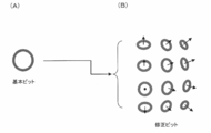
- FIG. 16A shows an example of a basic pit.
- FIG. 16B shows an example of a corrected pit.
- FIG. 17 is a detailed configuration example of the surface shape calculation unit.
- FIG. 16A shows an example of a basic pit.
- FIG. 16B shows an example of a corrected pit.
- FIG. 17 is a detailed configuration example of the surface shape calculation unit.
- FIG. 16A shows an example of a
- FIGS. 19A to 19F are explanatory diagrams of specific examples of classification processing.
- FIG. 20 is a detailed configuration example of a classification processing unit in the second classification processing method.
- FIG. 21 shows an example of classification types when a plurality of classification types are used. 22A to 22F show examples of pit patterns.
- FIG. 1A shows the relationship between the imaging unit 200 and the subject when observing an abnormal part (for example, an early lesion).
- FIG. 1B shows an example of an image acquired at that time.
- the normal gland duct 40 shows a normal pit pattern
- the abnormal gland duct 50 shows an abnormal pit pattern having an irregular shape
- the gland duct disappearing area 60 shows an abnormal area where the pit pattern has disappeared due to a lesion.
- FIG. 1A when an operator discovers an abnormal part (abnormal gland duct 50, gland duct disappearing region 60), the imaging part 200 is brought close to the abnormal part, and the imaging part 200 and the abnormal part are made as positive as possible. Make it counter.
- FIG. 1B regular structures are arranged in a uniform arrangement in the pit pattern of the normal part (normal gland duct 40).
- a normal pit pattern structure is registered or learned in advance as known characteristic information (foreseeing information), and the normal part is detected by matching processing or the like.
- an abnormal portion where the pit pattern has an irregular shape or disappears for example, an area where a normal pit pattern is not detected is regarded as an abnormal portion and is classified.
- misclassification may occur in an area where the amount of image information is small.
- the depth of field DA becomes very shallow (for example, several millimeters). Therefore, as shown in FIG. 1B, an out-of-focus region RB is likely to occur in the image. In such a region RB, since the accuracy of the matching process is lowered, even a region that should originally be classified as a normal part may be erroneously classified as an abnormal part and displayed as an abnormal part.
- the image processing apparatus includes an image acquisition unit 305 that acquires a captured image including an image of the subject, and distance information based on the distance from the imaging unit 200 to the subject at the time of imaging.
- a distance information acquisition unit 340 to be acquired a focus determination unit 370 that determines whether or not the subject is in focus in the pixel or region of the captured image based on the distance information, and a structure classification process of the subject
- a classification unit 310 that controls the target of the classification process according to the determination result in the pixel or region, and an enhancement processing unit 330 that performs the enhancement process of the captured image based on the result of the classification process.
- the pixel or the region determined to be out of focus is excluded from the target of the matching process, and is classified into “unknown” indicating that the classification of the pit pattern is unknown.
- matching processing is performed regardless of the result of the focus determination, and the pixel or region determined to be out of focus is reclassified as “unknown”.
- the distance information is information in which each position of the captured image is associated with the distance to the subject at each position.
- the distance in the optical axis direction of the imaging unit 200 is associated with each pixel. It is a distance map.
- the distance information is not limited to the distance map, and may be various information acquired based on the distance from the imaging unit 200 to the subject.
- the classification process is not limited to the pit pattern classification process, and may be any process that classifies the structure of the subject according to, for example, the type or state.
- the structure can assist the user's observation and diagnosis by presenting the classification result to the user.
- the polyp generated in the mucous membrane is not limited to the pit pattern.
- lesions such as gastrointestinal fistula, blood vessels, and cancer may be used.
- classification is made according to the type, the state of normal / abnormal, or the degree of abnormality.
- classification processes can be assumed as specific classification processes.
- the shape of the subject surface is obtained from the distance information, the reference pit pattern deformed according to the shape is matched with the image, and the pit pattern on the image is classified based on the matching result. May be.
- the pit patterns may be classified by matching the reference pit pattern and the image with, for example, POC (PhasePOOnly Correlation) without performing deformation using the distance information.
- the subject may be classified by extracting a specific structure such as a polyp or a groove.
- a specific structure such as a polyp or a groove.
- the stereo image is stereo-matched to obtain a distance map, and the low-pass filter process, the morphological process, and the like are performed on the distance map to obtain information on the general shape of the subject.
- the local shape information is obtained by subtracting the global shape information from the distance map.
- the known characteristic information of the structure to be classified (for example, the size and shape of a specific polyp, or the depth and width of a lesion-specific groove, etc.) is compared with the information of the local uneven structure, and the known characteristic information Extract the concavo-convex structure that matches In this way, specific structures such as polyps and grooves can be classified.
- the enhancement process is a process for conspicuous or identifying a specific target on the image.
- it may be a process for structure enhancement or color enhancement for an area classified into a specific type or state, or a process for highlighting the area, a process for surrounding the area with a line, or the area. It may be a process of attaching a mark indicating.
- the specific area may be made conspicuous (or identified) by performing the above-described processing on an area other than the specific area.
- FIG. 3 shows a configuration example of the endoscope device according to the first embodiment.
- the endoscope apparatus includes a light source unit 100, an imaging unit 200, a processor unit 300 (control device), a display unit 400, and an external I / F unit 500.
- the light source unit 100 includes a white light source 101, a rotating color filter 102 having a plurality of spectral transmittances, a rotation driving unit 103 that drives the rotating color filter 102, and light having spectral characteristics from the rotating color filter 102. And a condensing lens 104 that condenses light on the incident end face of the light guide fiber 201.
- Rotational color filter 102 is composed of three primary colors, a red color filter, a green color filter, a blue color filter, and a rotation motor.
- the rotation driving unit 103 rotates the rotating color filter 102 at a predetermined number of rotations in synchronization with the imaging period of the imaging elements 209 and 210 based on a control signal from the control unit 302 of the processor unit 300. For example, if the rotating color filter 102 is rotated 20 times per second, each color filter crosses the incident white light at 1/60 second intervals.
- the imaging elements 209 and 210 capture the reflected light from the observation target with respect to each of the three primary colors (R, G, or B) at intervals of 1/60 second, and transfer of the image is completed. That is, in this configuration example, an R image, a G image, and a B image are captured in a frame sequential manner at 1/60 second intervals, and the actual frame rate is 20 fps.
- the imaging unit 200 is formed to be elongated and bendable so that it can be inserted into a body cavity such as the stomach or the large intestine.
- the imaging unit 200 includes a light guide fiber 201 for guiding the light collected by the light source unit 100, an illumination lens 202 for diffusing the light guided to the tip by the light guide fiber 201 and irradiating the observation target, and an observation Objective lens systems 203 and 204 for collecting the reflected light returning from the object.
- the objective lens system 203 includes a zoom lens 205 that adjusts the optical magnification
- the objective lens system 204 includes a zoom lens 206 that adjusts the optical magnification.
- the imaging unit 200 detects imaging light condensed by the zoom lens driving unit 207 that drives the zoom lens 205, the zoom lens driving unit 208 that drives the zoom lens 206, and the objective lens systems 203 and 204. Imaging devices 209 and 210, and an A / D conversion unit 211 that converts an analog signal photoelectrically converted from the imaging devices 209 and 210 into a digital signal.
- the imaging unit 200 includes a memory 212 in which unique information including scope ID information and manufacturing variations of the imaging unit 200 is recorded, and a connector 213 that can be attached to and detached from the processor unit 300.
- Zoom lens driving units 207 and 208 are connected to the external I / F unit 500 and the control unit 302, and control the zoom lens position according to information input to the external I / F unit.
- the zoom lens driving units 207 and 208 are, for example, voice coil motors (hereinafter referred to as VCM).
- the image sensors 209 and 210 are, for example, monochrome single-plate image sensors, and for example, a CCD or a CMOS image sensor can be used.
- the objective lens systems 203 and 204 are arranged at positions separated by a predetermined distance, and are arranged at positions where a predetermined parallax image (hereinafter referred to as a stereo image) can be photographed.
- the image and the right image are formed.
- the left and right images output from the image sensors 209 and 210 are converted into digital signals by the A / D conversion unit 211, and the converted left and right images are output to the image processing unit 301.
- the memory 212 is connected to the control unit 302, and unique information including scope ID information and manufacturing variation is transferred from the memory 212 to the control unit 302.
- the processor unit 300 includes an image processing unit 301 (corresponding to the image processing apparatus) that performs various image processing on the image transferred from the A / D conversion unit 211, and a control unit that controls each unit of the endoscope apparatus. 302.
- the display unit 400 displays an image transferred from the image processing unit 301 and is a display device capable of displaying a moving image such as a CRT or a liquid crystal monitor.
- the external I / F unit 500 is an interface for performing input from the user to the endoscope apparatus.
- the external I / F unit 500 includes, for example, a power switch for turning on / off the power, a shutter button for starting a photographing operation, a mode switching switch for switching a photographing mode and other various modes (for example, a biological surface) And a switch for selectively emphasizing the structure.
- the external I / F unit 500 outputs input information to the control unit 302.
- the two observation modes are a normal observation mode and a close-up magnification observation mode.
- the normal observation mode is a mode in which screening observation is mainly performed using a pan-focus wide-field image.
- the close-up magnification observation mode is a mode for closely examining whether or not the lesioned part is malignant by magnifying and observing the mucosal structure, blood vessel running state, etc. in the vicinity of the lesioned part found by the screening observation.
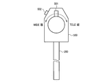
- FIG. 4 shows a configuration example of the external I / F unit 500 in the first embodiment.
- the above two modes are automatically switched when the user operates the zoom lever 501 in FIG. That is, when performing screening observation, the zoom lever 501 is set to the position of the WIDE end, and when performing close-up magnification observation, the zoom magnification is switched stepwise by turning the zoom lever 501 to the TELE end.
- FIG. 5 is a diagram illustrating a change in the depth of field of the imaging system with respect to the operation of the zoom lever 501.
- the imaging system is an imaging system including an objective lens system 203 (including a zoom lens 205) and an imaging element 209. The same applies to the imaging system including the objective lens system 204 (including the zoom lens 206) and the imaging element 210.
- the zoom lens 205 is set to a wide viewing angle position LP1.
- the zoom lens 205 is set to positions LP2 to LP4 by moving the zoom lever 501 stepwise (for example, in five steps) toward the TELE end.
- positions LP2 to LP4 the closer to the TELE side, the narrower the viewing angle, the closer the focusing distance, and the shallower the depth of field DF2 to DF4.
- the depth of field is shallow, but the closer observation is possible, and high magnification close-up observation is possible.
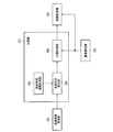
- FIG. 6 shows a detailed configuration example of the image processing unit 301 in the first embodiment.
- the image processing unit 301 includes a classification unit 310, an image configuration unit 320, an enhancement processing unit 330, a distance information acquisition unit 340 (distance map calculation unit), and a focus determination unit 370.
- a case where the pit pattern classification process is performed by the matching process will be described as an example, but various classification processes can be applied as described above.
- the distance information acquisition unit 340 acquires a stereo image output from the A / D conversion unit 211 and acquires distance information based on the stereo image. Specifically, the left image is used as a reference image, a matching operation with the local region of the right image is performed on the epipolar line passing through the pixel of interest located in the center of the local region of the left image, and the position having the maximum correlation is set as the parallax. calculate. Then, the calculated parallax is converted into a distance in the Z-axis direction to acquire distance information (for example, a distance map), and the distance information is output to the focus determination unit 370 and the classification unit 310.
- distance information for example, a distance map
- the distance information is various pieces of information acquired based on the distance from the imaging unit 200 to the subject.
- a distance based on an arbitrary point on a surface connecting two lenses generating parallax may be used as distance information.
- the distance information may be acquired by Time of Flight method. In this method, a subject is irradiated with laser light or the like, and the distance is measured based on the arrival time of the reflected light. In this case, for example, a distance based on each pixel position on the imaging element surface that captures the reflected light may be acquired as distance information.
- the reference point for distance measurement is set in the imaging unit 200, but the reference point may be set in any place other than the imaging unit 200.
- the reference point may be set at an arbitrary place in the three-dimensional space including the imaging unit 200 and the subject, and distance information when such a reference point is used is also included in the distance information of the present embodiment. .
- the distance from the imaging unit 200 to the subject is a distance in the depth direction from the imaging unit 200 to the subject, for example.
- the distance in the optical axis direction of the imaging unit 200 may be used. That is, the distance at a certain point on the subject is the distance from the imaging unit 200 to the subject on a line passing through that point and parallel to the optical axis.
- An example of such distance information is a distance map.
- the distance map is, for example, the distance (depth, depth) in the Z-axis direction to the subject for each point (for example, each pixel of the captured image) on the XY plane when the optical axis direction of the imaging unit 200 is the Z-axis. Is a map with the value of the point.
- the distance information acquisition unit 340 has a virtual position at a position where a magnitude relationship similar to the magnitude relationship of the distance values between pixels on the distance map acquired when the reference point is set in the imaging unit 200 can be maintained.
- distance information based on the distance from the imaging unit 200 to the corresponding point may be acquired. For example, when the actual distances from the imaging unit 200 to the three corresponding points are “3”, “4”, and “5”, the distances are uniformly maintained while maintaining the magnitude relationship of the distance values between the pixels. “1.5”, “2”, and “2.5” may be acquired.
- the image configuration unit 320 acquires a stereo image (left image and right image) output from the A / D conversion unit 211, and performs image processing (for example, OB processing) for converting the stereo image into an image that can be output to the display unit 400. , Gain processing, ⁇ processing, etc.).
- image processing for example, OB processing
- the image construction unit 320 outputs the processed image to the classification unit 310 and the enhancement processing unit 330.
- the focus determination unit 370 divides each pixel or each region of the captured image (for example, the captured image into regions of a predetermined size) by comparing the distance from the image capturing unit 200 to the subject and the depth of field of the image capturing unit 200. In each case, the focus determination is performed.
- FIG. 7 shows a detailed configuration example of the focus determination unit 370.
- the focus determination unit 370 includes a distance information correction unit 371 (distance map correction unit), a depth of field acquisition unit 372, a comparison unit 373, and a focus determination map output unit 374.
- the distance information is a distance map.
- the distance information correction unit 371 performs a low-pass filter process of a predetermined size of N ⁇ N pixels on the distance map input from the distance information acquisition unit 340.
- the distance map corrected in this way is output to the comparison unit 373.
- the depth of field acquisition unit 372 is connected to the control unit 302, and information on the zoom lens position is input from the control unit 302. As described above, the zoom lens position is set by the zoom lever 501, and the relationship described in FIG. 5 exists between the zoom lens position, the distance to the subject to be focused, and the depth of field. is there. Based on the input zoom lens position information, the depth-of-field acquisition unit 372 determines a focusing range (a range of distance to a subject to be focused) using, for example, a lookup table, and the focusing is performed. The range is output to the comparison unit 373.
- the look-up table may be set in advance based on the characteristics of the objective lens system 203 and 204.
- the comparison unit 373 compares the distance map input from the distance information correction unit 371 with the focus range information input from the depth-of-field acquisition unit 372 for each pixel, and whether each pixel is in focus or not. Determine.
- the focus determination result is output to the focus determination map output unit 374.
- the focus determination map output unit 374 creates a focus determination map based on the focus determination result input from the comparison unit, and outputs the focus determination map to the classification unit 310.
- the focus determination map is, for example, a map in which “1” is stored in the focused pixel and “0” is stored in the non-focused pixel. Data of the same size (the same number of pixels).
- the classification unit 310 performs a classification process for each pixel (or region) in the image based on the distance information and the classification standard. Specifically, the classification unit 310 includes a surface shape calculation unit 350 (three-dimensional shape calculation unit) and a classification processing unit 360. Details of the classification processing performed by the classification unit 310 will be described later, and an outline will be described here.
- the surface shape calculation unit 350 calculates the normal vector of the subject surface at each pixel of the distance map as surface shape information (three-dimensional shape information in a broad sense). Then, the classification processing unit 360 projects the reference pit pattern onto the subject surface based on the normal vector. Further, based on the distance at the pixel position, the size of the reference pit pattern is adjusted to the size on the image (that is, the apparent size that is smaller on the image as the distance is longer). The classification processing unit 360 performs matching processing between the reference pit pattern corrected in this way and the image, and detects an area that matches the reference pit pattern.
- the classification processing unit 360 sets the normal pit pattern shape as a reference pit pattern, classifies the region GR1 that matches the reference pit pattern as a “normal portion”, and does not match the region GR2 Is classified as “abnormal part” (non-normal part, lesion part).
- the classification processing unit 360 corrects the classification based on the result of the focus determination. Specifically, the classification of the region GR3 determined to be out of focus by the focus determination unit 370 is corrected to “unknown”. Alternatively, the out-of-focus pixels are excluded from the matching process and the classification is set to “unknown”, and the other pixels are matched and classified as “normal” and “abnormal”. Also good.
- the classification processing unit 360 outputs the classification result to the enhancement processing unit 330.
- unknown means that it is unknown which class it belongs to in classification processing classified into categories according to the type of structure, the state of normal / abnormality, etc., and the classification according to the degree of abnormality. For example, when classifying into “normal part” and “abnormal part”, those that cannot be determined (or are not determined) to belong to “normal part” or “abnormal part” are classified as “unknown”.
- the enhancement processing unit 330 Based on the classification result from the classification unit 310, the enhancement processing unit 330 performs a desired enhancement process on one of the stereo images output from the image configuration unit 320 (for example, a left image that is a reference for parallax calculation). Only for this, the processed image is output to the display unit 400. That is, the enhancement processing unit 330 does not output a stereoscopic image, and the display unit 400 performs 2D image display. For example, no enhancement processing is performed on the region GR1 whose classification result is “normal portion”, enhancement processing for luminance is performed on the region GR2 which is “abnormal portion”, and the region GR3 which is “unknown” is displayed. Performs processing to replace the pixel value with a specific color.
- the specific color to be replaced is preferably a unique color that is not included in a normal subject.
- the user wants to observe an area displayed in a specific color, the user operates the zoom lever 501 or changes the relative distance between the imaging unit 200 and the subject so that the area becomes a focused area. To do. By performing such an operation, the user can obtain a new classification result and observe the region.
- the classification unit 310 outputs a classification result (for example, “unknown”) corresponding to out-of-focus for a pixel or region in which it is determined that the subject is out-of-focus. Specifically, the classification unit 310 corrects the result of the classification process to the classification corresponding to the out-of-focus state for the pixel or the region in which the subject is determined to be out-of-focus.
- a classification result for example, “unknown”
- the classification result of the part where the subject is not in focus in the image is not output, the classification is different from the actual subject state in the part where the image is unclear due to defocusing. Even if it is misclassified, the misclassification is not highlighted. Thereby, the reliability of highlighting can be improved, and accurate information can be presented to the user to assist diagnosis.
- the classification unit 310 determines whether or not a pixel or a region matches a characteristic of a normal structure (for example, a basic pit as described later with reference to FIG. 16A). The area is classified into a normal part and an abnormal part (abnormal part). Then, the classification unit 310 corrects the classification result of the normal part and the abnormal part to the unknown state in which the classification of the normal part and the abnormal part is unknown for the pixel or the region in which the subject is determined to be out of focus. To do.
- a normal structure for example, a basic pit as described later with reference to FIG. 16A.
- the subject can be classified into, for example, a normal part where a normal pit pattern exists and a non-normal part other than that. Then, it can be prevented that the portion in which the image is unclear due to the out-of-focus state is erroneously classified into the non-normal portion even though the normal pit pattern actually exists.
- the abnormal parts may be further grouped into subdivided classifications. Even in such a case, the subdivided classification may be erroneously determined by motion blur, but according to the present embodiment, such erroneous determination can be suppressed.
- the classification unit 310 may exclude pixels or regions in which the subject is determined to be out-of-focus from the target of the classification process and set the classification or classification corresponding to out-of-focus.
- misclassification can be suppressed and accurate information can be presented to the user.
- the classification result of the out-of-focus area to “unknown (unknown state)”
- the matching process is not performed on the out-of-focus pixel or region, the processing load can be reduced.
- FIG. 9 shows a configuration example of an endoscope device according to the second embodiment.
- the endoscope apparatus includes a light source unit 100, an imaging unit 200, a processor unit 300, a display unit 400, and an external I / F unit 500.
- the same components as those in the first embodiment are denoted by the same reference numerals, and description thereof will be omitted as appropriate.
- the difference from the first embodiment is the configuration of the objective lens systems 203 and 204 of the imaging unit 200. That is, the objective lens systems 203 and 204 further include focus lenses 214 and 215.
- the imaging unit 200 further includes focus lens driving units 216 and 217 that drive the focus lenses 214 and 215.
- the focus lens driving units 216 and 217 are, for example, VCMs.
- the processor unit 300 further includes a focus control unit 303.
- FIG. 10 shows a configuration example of the external I / F unit 500 in the second embodiment.
- the external I / F unit 500 includes a zoom lever 501 and an AF button 502.
- the zoom lever 501 can be operated continuously within a certain range, and the user can continuously adjust the zoom lens position from the WIDE end to the TELE end by moving the zoom lever 501.
- the external I / F unit 500 outputs position information of the zoom lever 501 to the control unit 302.
- the external I / F unit 500 outputs an AF start signal to the control unit 302 when the AF button 502 is pressed.
- FIG. 11 shows a detailed configuration example of the focus control unit 303.
- the focus control unit 303 includes a focus lens drive mode determination unit 381, a focus lens position determination unit 382, and an AF control unit 383 (AF: autofocus).
- AF autofocus
- the focus lens drive mode determination unit 381 determines the focus lens drive mode based on the zoom lens position information and AF start information input from the control unit 302.
- the focus lens drive mode determination unit 381 selects the fixed focus mode when the zoom lens position is located on the WIDE side with respect to a predetermined position, and uses the zoom lens position information as the focus lens position determination unit 382. Output to.
- the focus lens drive mode determination unit 381 selects the fixed focus mode even when the zoom lens position is closer to the TELE side than the predetermined position and no AF start signal is input from the external I / F unit 500. Information on the zoom lens position is output to the focus lens position determination unit 382.
- the focus lens position determination unit 382 determines the focus lens position based on the zoom lens position information, and outputs the determined focus lens position information to the focus lens driving units 216 and 217. Since the focus changes when the zoom lens position changes, for example, a table in which the position of the focus lens that realizes the fixed focus is associated with each zoom lens position is stored, and the position of the focus lens is referred to by referring to the table. Just decide.
- the focus lens driving units 216 and 217 drive the focus lenses 214 and 215 based on the focus lens position information input from the focus lens position determination unit 382.
- the focus lens drive mode determination unit 381 selects the AF mode when the zoom lens position is closer to the TELE side than the predetermined position and an AF start signal is input from the external I / F unit 500, and AF start The signal is output to the AF control unit 383.
- the AF control unit 383 outputs an AF status signal set to a status of “being executed” to the image processing unit 301 and starts an AF operation. To do.
- the AF control unit 383 calculates a contrast value from the image input from the image processing unit 301, and drives the focus lenses 214 and 215 based on a known contrast AF method.
- the AF control unit 383 outputs information on the focus lens position to the image processing unit 301 every time the focus lenses 214 and 215 are driven.
- the AF control unit 383 determines whether or not the in-focus state is obtained from the calculated contrast value. When the in-focus state is determined, the AF operation is terminated and the AF status signal set to the status of “stopped”. Is output to the image processing unit 301.
- the reason why the fixed focus mode and the AF mode are switched depending on the zoom lens position is that the depth of field differs depending on the zoom lens position as described with reference to FIG. That is, when the zoom lens position is on the WIDE side, the depth of field is sufficiently deep and AF control is not required. However, when the zoom lens position is on the TELE side, the depth of field becomes shallow and AF control is performed. Is based on the assumption that
- FIG. 12 shows a detailed configuration example of the focus determination unit 370 in the second embodiment.
- the focus determination unit 370 includes a distance information correction unit 371, a depth of field acquisition unit 372, a comparison unit 373, and a focus determination map output unit 374.
- the basic configuration is the same as in the first embodiment. The difference is that not only the control unit 302 but also the AF control unit 383 is connected, and the operation of the depth of field acquisition unit 372.
- the AF status signal input from the AF control unit 383 is “stopped” (that is, the fixed focus mode)
- the operation of the depth of field acquisition unit 372 is the same as that of the first embodiment.
- the depth-of-field acquisition unit 372 receives the zoom position information input from the control unit 302 and the focus lens input from the AF control unit 383. Based on the position information, a focus range is determined using a preset look-up table or the like, and the determined focus range is output to the comparison unit 373.
- classification processing unit 360 in the second embodiment will be described.
- the classification processing unit 360 is connected to the AF control unit 383.
- the operation of the classification processing unit 360 is the same as that of the first embodiment.
- the classification processing unit 360 When the AF status signal is “being executed”, the classification processing unit 360 performs a matching process between the classification standard corrected based on the distance information and the image, and classifies the subject into, for example, “normal part” and “abnormal part”. To do. Further, the classification processing unit 360 corrects the classification based on the focus determination map input from the focus determination unit 370. The classification processing unit 360 holds a plurality of classification results and a plurality of in-focus determination maps during a period in which the AF status signal is “in execution”. Then, one corrected classification is determined based on a plurality of classification results and a plurality of focus determination maps.
- a plurality of in-focus maps are compared, and a pixel having an in-focus map that is determined to be in focus is classified into a classification obtained by correcting the classification result at the time of in-focus. Pixels for which there is no in-focus map that is determined to be in focus are corrected to an unknown classification.
- the classification processing unit 360 outputs the classification result classified as “normal part”, “abnormal part”, or “unknown” to the enhancement processing unit 330.
- the operation of the classification processing unit 360 will be described using FIG. 13 as an example in which the classification is corrected using the focus determination map of the two frames F1 and F2.
- the frames F1 and F2 are a series of frames taken during the AF operation. Since the in-focus range varies depending on the movement of the lens position in the AF operation, the “in-focus” area is different for each frame in the in-focus determination map.
- the area AA1 is “in focus” and the other area AA2 is “out of focus” in the focus determination map of the frame F1.
- the area AA1 is classified as “normal”, and the area AA2 is classified as “abnormal part” because the image is blurred.
- This classification map is corrected by the focus determination map, and the area AA2 is reclassified to “unknown”.
- the “in-focus” area AB1 is classified as “normal”, and the classification of the “in-focus” area AB2 is corrected from “abnormal” to “unknown”.
- the corrected classification maps of the frames F1 and F2 are compared, and a pixel that is “normal” is classified as “normal”, and a pixel that is “unknown” is classified as “unknown”. .
- the area AC1 obtained by combining the “normal” areas AA1 and AB1 in the frames F1 and F2 is classified as “normal” and output as a final classification map.
- the AF control unit 383 controls the autofocus operation of the imaging unit 200. Then, the focus determination unit 370 determines whether or not the subject is in focus in each frame of a plurality of frames (for example, frames F1 and F2) that perform the autofocus operation.
- the classification unit 310 applies the classification processing result in the frame (the “normal part” of the regions AA1 and AB1 in FIG. 13) for the pixel or region in which the subject is determined to be in focus in any one of the plurality of frames. ”) As a final classification result (" normal part "of the area AC1).
- the final classification result can be output by using the information (focus determination map, classification map) acquired at a plurality of focus lens positions in combination.
- the information focus determination map, classification map
- Area can be narrowed. Thereby, it is possible to display the classification result with high reliability performed in the in-focus area in a wider area.
- First classification processing method 4.1 Classification Unit
- the classification process performed by the classification unit 310 according to the first and second embodiments described above will be described in detail.
- FIG. 14 shows a detailed configuration example of the classification unit 310.
- the classification unit 310 includes a known characteristic information acquisition unit 345, a surface shape calculation unit 350, and a classification processing unit 360.
- the operation of the classification unit 310 will be described taking the case where the observation target is the large intestine as an example.
- the living body surface 1 of the large intestine to be observed has a polyp 2 of a raised lesion, and the mucosal surface layer of the polyp 2 has a normal gland duct 40 and an abnormal gland duct 50. It shall be.
- a concave lesion 60 in which the gland duct structure has disappeared exists at the base of the polyp 2.
- the normal gland duct 40 has a substantially circular shape
- the abnormal gland duct 50 has a shape that is different from that of the normal gland duct 40. Presents.
- the surface shape calculation unit 350 performs a closing process or an adaptive low-pass filter process on the distance information (for example, a distance map) input from the distance information acquisition unit 340, thereby obtaining a size equal to or larger than the size of the predetermined structural element. Extract the structure.
- the predetermined structural element is a gland duct structure (pit pattern) to be classified and determined formed on the biological surface 1 of the observation site.
- the known characteristic information acquisition unit 345 acquires structural element information as one of the known characteristic information, and outputs the structural element information to the surface shape calculation unit 350.
- the structural element information is size information determined by the optical magnification of the imaging unit 200 and the size (width information) of the gland duct structure to be classified from the surface structure of the living body surface 1. That is, the optical magnification is determined according to the distance to the subject, and the size on the image of the gland duct structure imaged at that distance is acquired as the structural element information by adjusting the size with the optical magnification.
- the control unit 302 of the processor unit 300 stores the standard size of the gland duct structure, and the known characteristic information acquisition unit 345 acquires the size from the control unit 302 and performs size adjustment based on the optical magnification.
- the control unit 302 determines an observation site based on scope ID information input from the memory 212 of the imaging unit 200. For example, when the imaging unit 200 is an upper digestive scope, the observation site is determined to be the esophagus, stomach, and duodenum, and when the imaging unit 200 is the lower digestive scope, the observation site is determined to be the large intestine. In the control unit 302, standard gland duct sizes corresponding to these observation sites are recorded in advance.
- a method for determining an observation site other than the scope ID for example, there is a method in which the external I / F unit 500 has a switch that can be operated by the user, and the user selects the observation site using the switch.
- the surface shape calculation unit 350 adaptively generates surface shape calculation information based on the input distance information, and calculates the surface shape information of the subject using the surface shape calculation information.
- the surface shape information is, for example, a normal vector NV shown in FIG. Details of the surface shape calculation information will be described later.
- the generated surface shape information is input to the classification processing unit 360 together with the distance map.
- the classification processing unit 360 generates a corrected pit (classification standard) by adapting the basic pit to the three-dimensional shape of the living body surface of the captured image.
- the basic pit is obtained by modeling one normal gland duct structure for classifying the gland duct structure, and is, for example, a binary image.
- the terms basic pit and correction pit are used. However, a broader term can be replaced with a reference pattern and a correction pattern.
- the classification processing unit 360 performs a classification process based on the generated classification standard (corrected pit). Specifically, an image from the image construction unit 320 is further input to the classification processing unit 360. The classification processing unit 360 determines whether or not the corrected pit is present on the captured image by a known pattern matching process, and outputs a classification map in which the classification areas are grouped to the enhancement processing unit 330.
- the classification map is a map in which captured images are classified into an area where a correction pit exists and other areas. For example, it is a binary image in which “1” is assigned to the pixels in the area where the correction pit exists and “0” is assigned to the pixels in the other areas. In the case where the classification of “unknown” is set according to the focus determination, for example, “2” may be assigned to the pixels in the “unknown” area to form a ternary image.
- the image from the image construction unit 320 (the same size as the classified image) is further input to the enhancement processing unit 330.
- the enhancement processing unit 330 performs enhancement processing on the image output from the image construction unit 320 using information indicating the classification result.
- FIG. 15A is a cross-sectional view of the living body surface 1 of the subject and the imaging unit 200 in a cross section along the optical axis of the imaging unit 200, and shows a state in which the surface shape is calculated by morphological processing (closing processing). It is a schematic one.
- the radius of the sphere SP (structural element) used for the closing process is, for example, at least twice (including its value) the size (surface shape calculation information) of the gland duct structure to be classified. As described above, the size of the duct structure is adjusted to the size on the image in accordance with the distance to the subject at each pixel.
- the surface 3 of the living body 1 that is smoother than the minute irregularities without picking up the minute irregularities of the normal gland duct 40, the abnormal gland duct 50, and the gland duct disappearing region 60 is used.
- Dimensional surface shape can be extracted. Therefore, the correction error can be reduced as compared with the case where the basic pit is corrected to the corrected pit using the surface shape with minute unevenness left.
- FIG. 15B is a cross-sectional view of the surface of the living body after the closing process, and schematically shows a result of calculating the normal vector NV with respect to the surface of the living body.
- the surface shape information is this normal vector NV.
- the surface shape information is not limited to the normal vector NV, and may be the curved surface itself after the closing process shown in FIG. 15B, or other information that can express the surface shape. Also good.
- the known characteristic information acquisition unit 345 acquires the gland duct size (width in the longitudinal direction, etc.) inherent to the living body as known characteristic information, and uses that information to trace the actual living body surface by the closing process.
- the radius of the sphere SP (radius corresponding to the size of the gland duct on the image) is determined. At this time, the radius of the sphere SP is set to a radius larger than the size of the gland duct on the image.
- the surface shape calculation unit 350 can extract only a desired surface shape by performing a closing process using the sphere SP.
- FIG. 17 shows a detailed configuration example of the surface shape calculation unit 350.
- the surface shape calculation unit 350 includes a morphological characteristic setting unit 351, a closing processing unit 352, and a normal vector calculation unit 353.
- the known characteristic information acquisition unit 345 inputs the size of the gland duct unique to the living body (width in the longitudinal direction, etc.), which is known characteristic information, to the morphological characteristic setting unit 351.
- the morphological characteristic setting unit 351 determines surface shape calculation information (such as the radius of the sphere SP used for the closing process) based on the size of the gland duct and the distance map.
- the radius information of the determined sphere SP is input to the closing processing unit 352 as a radius map having the same number of pixels as the distance map, for example.
- the radius map is a map in which information on the radius of the sphere SP at each pixel is associated with each pixel.
- the closing processing unit 352 performs the closing process by changing the radius in units of pixels based on the radius map, and outputs the processing result to the normal vector calculation unit 353.
- the distance vector after the closing process is input to the normal vector calculation unit 353.
- the normal vector calculation unit 353 has three-dimensional information (for example, pixel coordinates and distance information at the coordinates) at the target sample position on the distance map, and 3 at two sample positions adjacent to the target sample position. A plane is defined based on the dimension information, and a normal vector of the defined plane is calculated.
- the normal vector calculation unit 353 outputs the calculated normal vector to the classification processing unit 360 as a normal vector map having the same sampling number as the distance map.
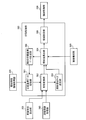
- FIG. 18 shows a detailed configuration example of the classification processing unit 360.
- the classification processing unit 360 includes a classification reference data storage unit 361, a projective transformation unit 362, a search region size setting unit 363, a similarity calculation unit 364, and a region setting unit 365.
- the classification reference data storage unit 361 stores basic pits that model normal gland ducts exposed on the surface of a living body shown in FIG. This basic pit is a binary image, which is an image having a size corresponding to a case where a normal gland duct at a predetermined distance is imaged.
- the classification reference data storage unit 361 outputs this basic pit to the projective transformation unit 362.
- the projection conversion unit 362 receives the distance map from the distance information acquisition unit 340, the normal vector map from the surface shape calculation unit 350, and the optical magnification from the control unit 302 (not shown).
- the projective transformation unit 362 extracts distance information of the target sample position from the distance map, and extracts a normal vector of the corresponding sample position from the normal vector map. Then, as shown in FIG. 16B, projective transformation of the basic pit is performed using the normal vector, and magnification correction is performed in accordance with the optical magnification to generate a corrected pit.
- Projection conversion unit 362 outputs the corrected pit as a classification reference to similarity calculation unit 364 and outputs the size of the corrected pit to search region size setting unit 363.
- the search area size setting unit 363 sets an area that is twice as long as the corrected pit size as a search area for the similarity calculation process, and outputs information on the search area to the similarity calculation unit 364.
- the similarity calculation unit 364 receives a corrected pit at the target sample position from the projective conversion unit 362 and a search area corresponding to the corrected pit from the search area size setting unit 363. The similarity calculation unit 364 extracts the image of the search area from the image input from the image construction unit 320.
- the similarity calculation unit 364 performs high-pass filter processing or band-pass filter processing on the extracted search region image to cut low-frequency components, and binarization processing is performed on the filtered image. To generate a binary image of the search area. Then, the correlation value is calculated by performing pattern matching processing on the binary image in the search area with the corrected pit, and a map of the peak position of the correlation value and the maximum correlation value is output to the area setting unit 365. For example, the correlation value is the sum of absolute differences, and the maximum correlation value is the minimum value of the sum of absolute differences.
- POC Phase Only Correlation
- the region setting unit 365 Based on the maximum correlation value map input from the similarity calculation unit 364, the region setting unit 365 extracts a region where the sum of absolute differences is equal to or less than a predetermined threshold T (including that value), and further, A three-dimensional distance between the position of the maximum correlation value and the position of the maximum correlation value in the adjacent search range is calculated. If the calculated three-dimensional distance is included in the range of the predetermined error, the region including the maximum correlation position is grouped as a normal region, and a classification map is generated. The region setting unit 365 outputs the generated classification map to the enhancement processing unit 330.
- T including that value
- a position in an image is set as a processing target position.
- the projective transformation unit 362 acquires a correction pattern at the processing target position by deforming the reference pattern based on the surface shape information at the processing target position.
- the search area size setting unit 363 searches the search area around the processing target position from the acquired correction pattern (in the above example, an area having a size twice the vertical and horizontal directions of the correction pattern). ) Is set.
- the similarity calculation unit 364 matches the imaged structure and the correction pattern in the search area. If this matching is performed on a pixel basis, the similarity is calculated for each pixel. Then, as illustrated in FIG. 19E, the region setting unit 365 identifies a pixel corresponding to the similarity peak in the search region, and whether or not the similarity in the pixel is equal to or greater than a given threshold value. Determine whether. If the similarity is greater than or equal to the threshold value, correction is made to a region of the size of the correction pattern with reference to the peak position (in FIG. 19E, the center position of the correction pattern is used as the reference position, but is not limited to this). Since the pattern is detected, the area can be classified as an area that matches the reference pattern.
- the inside of the shape representing the correction pattern may be an area that matches the classification criteria, and various modifications can be made.
- the similarity is less than the threshold value, there is no structure matching the reference pattern in the peripheral region of the processing target position.
- a region that matches zero, one, or a plurality of reference patterns and other regions are set in the captured image. If there are a plurality of regions that match the reference pattern, the classification results are finally obtained by integrating those overlapping or adjacent ones.
- the classification processing method based on the similarity described here is an example, and the classification processing may be performed by another method.
- specific methods for calculating the similarity various methods for calculating the similarity between images and the difference between images are known, and detailed description thereof will be omitted.
- the classification unit 310 generates the classification reference based on the surface shape calculation unit 350 that obtains the surface shape information of the subject based on the distance information and the known characteristic information, and generates the classification reference based on the surface shape information.
- a classification processing unit 360 that performs a classification process using the classification criterion.
- There are various factors that can reduce the accuracy of the classification process depending on the surface shape such as the deformation of the structure on the captured image caused by the angle formed by the optical axis direction of the imaging unit 200 and the surface of the subject. Therefore, even in such a case, classification processing can be performed with high accuracy.
- the known characteristic information acquisition unit 345 acquires a reference pattern corresponding to the structure of the subject in a given state as known characteristic information, and the classification processing unit 360 is based on the surface shape information with respect to the reference pattern.
- a correction pattern acquired by performing the deformation process may be generated as a classification standard, and the classification process may be performed using the generated classification standard.
- the known characteristic information acquisition unit 345 acquires a reference pattern corresponding to the structure of the subject in a normal state as acquisition of known characteristic information.
- An abnormal region is a region suspected of being a lesioned part of a living body, for example, in the case of an endoscope for a living body. Since it is assumed that such a region has a high degree of attention for the user, it is possible to suppress oversight of a region to be noticed by appropriately classifying the region.
- the subject has a global three-dimensional structure and a local uneven structure compared to the global three-dimensional structure, and the surface shape calculation unit 350 has a global three-dimensional structure that the subject has.
- surface shape information may be obtained by extracting a global three-dimensional structure from the distance information.
- the classification process can be performed with high accuracy by obtaining the surface shape information from the global three-dimensional structure.
- FIG. 20 shows a detailed configuration example of the classification processing unit 360 in the second classification processing method.
- the classification processing unit 360 includes a classification reference data storage unit 361, a projective transformation unit 362, a search region size setting unit 363, a similarity calculation unit 364, a region setting unit 365, and a second classification reference data generation unit 366.
- symbol is attached
- the basic pit that is the classification standard is prepared not only for the normal gland duct but also for the abnormal gland duct, and the pit of the actual captured image is extracted, and the second classification standard data
- the classification reference data is replaced as (second reference pattern), and the similarity is recalculated based on the second classification reference data after the replacement.
- the pit pattern on the surface of the living body depends on whether it is in a normal state or an abnormal state. It is known that the shape changes depending on the degree of progress of the above. For example, in the case of a normal mucous membrane, the pit pattern is almost circular as shown in FIG. 22 (A), and when the lesion progresses, the star pod shape in FIG. 22 (B), or in FIG. 22 (C) and FIG. If it becomes a complicated shape such as a tubular type and further proceeds, the pit pattern disappears as shown in FIG. Therefore, it is possible to determine the state of the subject by holding these typical patterns as reference patterns and determining the degree of similarity between the surface of the subject captured in the captured image and the reference pattern. .
- the classification reference data storage unit 361 not only basic pits of normal ducts but also a plurality of pits as shown in FIG. 21 are recorded, and these pits are output to the projective conversion unit 362.
- the processing of the projective transformation unit 362 is the same as the first classification processing method. That is, projective transformation processing is performed on all the pits stored in the classification reference data storage unit 361, and corrected pits for a plurality of classification types are output to the search area size setting unit 363 and the similarity calculation unit 364.
- the similarity calculation unit 364 generates respective maximum correlation value maps for a plurality of corrected pits. Note that the maximum correlation value map at this point is not used for generation of the classification map (generation of the final output of the classification process), but is output to the second classification reference data generation unit 366 to generate new classification reference data. Will be used to generate
- the second classification criterion data generation unit 366 newly classifies the pit image at the position on the image determined by the similarity calculation unit 364 as having high similarity (for example, the difference absolute value is equal to or less than a predetermined threshold). Adopt as. Thereby, since the pit extracted from the actual image is used as the classification reference instead of the standard modeled pit prepared in advance, the classification determination with more optimum accuracy is possible.
- the second classification reference data generation unit 366 includes a maximum correlation value map for each classification from the similarity calculation unit 364, an image from the image configuration unit 320, and a distance from the distance information acquisition unit 340.
- the map, the optical magnification from the control unit 302, and the gland duct size for each classification from the known characteristic information acquisition unit 345 are input. Then, the second classification reference data generation unit 366 extracts image data corresponding to the sample position of the maximum correlation value for each classification based on the distance information of the position, the size of the gland duct, and the optical magnification.
- the second classification reference data generation unit 366 acquires a grayscale image (in order to cancel the difference in brightness) obtained by removing the low frequency component from the extracted actual image, and uses the grayscale image as the second classification.
- the reference data is output to the classification reference data storage unit 361 together with the normal vector and the distance information.
- the classification reference data storage unit 361 stores the second classification reference data and related information. As a result, the second classification reference data having high correlation with the subject can be collected in each classification.
- the second classification reference data described above excludes the influence of deformation (change in size) due to the angle between the optical axis direction of the imaging unit 200 and the subject surface and the distance from the imaging unit 200 to the subject surface.
- the second classification reference data generation unit 366 may generate the second classification reference data after performing a process for canceling the influence thereof.
- the result of performing deformation processing (projection conversion processing and scaling processing) on the gray scale image so as to correspond to the case where the image is captured at a given distance from a given reference direction. May be the second classification reference data.
- the projection conversion unit 362, the search area size setting unit 363, and the similarity calculation unit 364 may perform the process again for the second classification reference data. Specifically, projective transformation processing is performed on the second classification reference data to generate a second correction pattern, and the same processing as the first classification processing method is performed using the generated second correction pattern as a classification reference. I do.
- the region setting unit 365 is grouped according to the classification map (I type, II type,%) Shown in FIG. 21 or according to the classification type (type A, B,...) Shown in FIG. Generate a classification map. Specifically, a classification map is generated for areas that have been correlated with corrected pits that are classified as normal ducts, and a classification map for areas that have been correlated with corrected pits that are classified as abnormal ducts is classified by category. Generate by type. Then, a classification map (multi-valued image) obtained by combining these classification maps is generated. When synthesizing, the overlapping area of the areas where the correlation is obtained in each classification may be an unclassified area or may be replaced with a classification with a higher malignancy level. The region setting unit 365 outputs the combined classification map to the enhancement processing unit 330.
- the enhancement processing unit 330 performs, for example, luminance or color enhancement processing based on the multi-valued image classification map.
- the known characteristic information acquisition unit 345 acquires the reference pattern corresponding to the structure of the subject in the abnormal state as acquisition of the known characteristic information.
- FIG. 21 it is possible to acquire a plurality of reference patterns, generate a classification reference using them, and perform a classification process. That is, by performing classification processing using typical patterns as shown in FIGS. 22A to 22F as reference patterns, the state of the subject can be classified in detail.
- the known characteristic information acquisition unit 345 acquires a reference pattern corresponding to the structure of the subject in a given state as known characteristic information, and the classification processing unit 360 is based on the surface shape information with respect to the reference pattern.
- a correction pattern is obtained by performing deformation processing, and the degree of similarity between the structure of the subject captured in the captured image and the correction pattern is obtained at each image position of the captured image, and based on the obtained similarity,
- a second reference pattern candidate may be acquired.
- category process part 360 produces
- the second correction pattern acquired by performing the deformation process based on the shape information may be generated as a classification standard, and the classification process may be performed using the generated classification standard.
- the classification reference since a classification reference can be created from the subject actually captured in the captured image, the classification reference well reflects the characteristics of the subject to be processed, and the reference pattern acquired as the known characteristic information is used. Compared with the case where it is used as it is, the accuracy of the classification process can be further improved.
- each unit configuring the image processing unit 301 is configured by hardware.
- the CPU may be configured to perform processing of each unit on an image and distance information acquired in advance using the imaging device, and may be realized as software by the CPU executing a program.
- a part of processing performed by each unit may be configured by software.
- the program stored in the information storage medium is read, and the read program is executed by a processor such as a CPU.
- the information storage medium (computer-readable medium) stores programs, data, and the like.
- Information storage media are equipped with CD-ROM and USB memory, as well as “portable physical media” including MO discs, DVD discs, flexible discs (FD), magneto-optical discs, IC cards, etc., inside and outside the computer system.
- Programs such as “fixed physical media” such as HDD, RAM, and ROM, public lines connected via modems, local area networks or wide area networks to which other computer systems or servers are connected It includes any recording medium that records a program that can be read by a computer system, such as a “communication medium” that stores a program in a short time during transmission.
- the program is recorded on the above recording medium so as to be readable by a computer, and the computer system (an apparatus including an operation unit, a processing unit, a storage unit, and an output unit) reads the program from such a recording medium.
- the computer system an apparatus including an operation unit, a processing unit, a storage unit, and an output unit
- the program is not limited to be executed by a computer system, and when another computer system or server executes the program, or when they cooperate to execute the program, The present invention can be similarly applied.
- the hardware image processing apparatus may be executed in the same manner, or a program describing the processing procedure of the method may be executed by the CPU. May be executed.
Landscapes
- Engineering & Computer Science (AREA)
- Health & Medical Sciences (AREA)
- Life Sciences & Earth Sciences (AREA)
- Physics & Mathematics (AREA)
- Surgery (AREA)
- General Health & Medical Sciences (AREA)
- General Physics & Mathematics (AREA)
- Theoretical Computer Science (AREA)
- Molecular Biology (AREA)
- Nuclear Medicine, Radiotherapy & Molecular Imaging (AREA)
- Medical Informatics (AREA)
- Biomedical Technology (AREA)
- Radiology & Medical Imaging (AREA)
- Optics & Photonics (AREA)
- Biophysics (AREA)
- Animal Behavior & Ethology (AREA)
- Pathology (AREA)
- Veterinary Medicine (AREA)
- Public Health (AREA)
- Heart & Thoracic Surgery (AREA)
- Computer Vision & Pattern Recognition (AREA)
- Multimedia (AREA)
- Signal Processing (AREA)
- Astronomy & Astrophysics (AREA)
- Data Mining & Analysis (AREA)
- Quality & Reliability (AREA)
- Geometry (AREA)
- Artificial Intelligence (AREA)
- General Engineering & Computer Science (AREA)
- Evolutionary Biology (AREA)
- Bioinformatics & Cheminformatics (AREA)
- Bioinformatics & Computational Biology (AREA)
- Evolutionary Computation (AREA)
- Endoscopes (AREA)
- Instruments For Viewing The Inside Of Hollow Bodies (AREA)
Abstract
L'invention concerne un dispositif de traitement d'image qui comprend : une unité d'acquisition d'image (305) qui acquiert des images capturées qui comprennent une image d'un sujet ; une unité d'acquisition d'informations de distance (340) qui acquiert des informations de distance sur la base d'une distance d'une unité d'imagerie (200) au sujet pendant l'imagerie ; une unité de détermination de foyer (370) qui détermine si le sujet est dans un foyer dans des pixels ou dans une région des images capturées sur la base des informations de distance ; une unité de classification (310) qui réalise un traitement de classification sur la structure du sujet et commande un objet du traitement de classification en fonction du résultat de détermination dans les pixels ou la région ; et une unité de traitement d'accentuation (330) qui réalise un traitement d'accentuation sur les images capturées sur la base des résultats de traitement de classification.
Priority Applications (3)
| Application Number | Priority Date | Filing Date | Title |
|---|---|---|---|
| CN201380075135.8A CN105072968A (zh) | 2013-03-27 | 2013-09-25 | 图像处理装置、内窥镜装置、程序和图像处理方法 |
| EP13880187.3A EP2979606A4 (fr) | 2013-03-27 | 2013-09-25 | Dispositif de traitement d'image, dispositif endoscopique, programme et procédé de traitement d'image |
| US14/861,209 US20160014328A1 (en) | 2013-03-27 | 2015-09-22 | Image processing device, endoscope apparatus, information storage device, and image processing method |
Applications Claiming Priority (2)
| Application Number | Priority Date | Filing Date | Title |
|---|---|---|---|
| JP2013-067423 | 2013-03-27 | ||
| JP2013067423A JP6049518B2 (ja) | 2013-03-27 | 2013-03-27 | 画像処理装置、内視鏡装置、プログラム及び画像処理装置の作動方法 |
Related Child Applications (1)
| Application Number | Title | Priority Date | Filing Date |
|---|---|---|---|
| US14/861,209 Continuation US20160014328A1 (en) | 2013-03-27 | 2015-09-22 | Image processing device, endoscope apparatus, information storage device, and image processing method |
Publications (1)
| Publication Number | Publication Date |
|---|---|
| WO2014155782A1 true WO2014155782A1 (fr) | 2014-10-02 |
Family
ID=51622822
Family Applications (1)
| Application Number | Title | Priority Date | Filing Date |
|---|---|---|---|
| PCT/JP2013/075869 WO2014155782A1 (fr) | 2013-03-27 | 2013-09-25 | Dispositif de traitement d'image, dispositif endoscopique, programme et procédé de traitement d'image |
Country Status (5)
| Country | Link |
|---|---|
| US (1) | US20160014328A1 (fr) |
| EP (1) | EP2979606A4 (fr) |
| JP (1) | JP6049518B2 (fr) |
| CN (1) | CN105072968A (fr) |
| WO (1) | WO2014155782A1 (fr) |
Cited By (5)
| Publication number | Priority date | Publication date | Assignee | Title |
|---|---|---|---|---|
| EP3029629A1 (fr) * | 2014-11-07 | 2016-06-08 | Casio Computer Co., Ltd. | Appareil de diagnostic et procédé de traitement d'image dans le même appareil |
| US9818183B2 (en) | 2014-11-07 | 2017-11-14 | Casio Computer Co., Ltd. | Disease diagnostic apparatus, image processing method in the same apparatus, and medium storing program associated with the same method |
| US9836836B2 (en) | 2014-11-07 | 2017-12-05 | Casio Computer Co., Ltd. | Disease diagnostic apparatus, image processing method in the same apparatus, and medium storing program associated with the same method |
| EP3357402A4 (fr) * | 2015-09-28 | 2018-10-03 | FUJIFILM Corporation | Système d'endoscope et procédé de fonctionnement du système d'endoscope |
| JP2021509070A (ja) * | 2018-03-07 | 2021-03-18 | コーニンクレッカ フィリップス エヌ ヴェKoninklijke Philips N.V. | 皮膚パラメータの測定のための装置、システム及び方法 |
Families Citing this family (29)
| Publication number | Priority date | Publication date | Assignee | Title |
|---|---|---|---|---|
| JP5556133B2 (ja) * | 2009-03-31 | 2014-07-23 | 日立化成株式会社 | 電子部品用液状樹脂組成物及び電子部品装置 |
| JP6453904B2 (ja) * | 2014-12-02 | 2019-01-16 | オリンパス株式会社 | フォーカス制御装置、内視鏡装置及びフォーカス制御装置の制御方法 |
| DE112015006378T5 (de) * | 2015-04-23 | 2017-12-14 | Olympus Corporation | Bildverarbeitungsvorrichtung, Bildverarbeitungsverfahren und Bildverarbeitungsprogramm |
| JP6603709B2 (ja) | 2015-04-23 | 2019-11-06 | オリンパス株式会社 | 画像処理装置、画像処理方法および画像処理プログラム |
| US9703175B2 (en) * | 2015-07-02 | 2017-07-11 | Qualcomm Incorporated | Systems and methods for autofocus trigger |
| US20170061586A1 (en) * | 2015-08-28 | 2017-03-02 | Nokia Technologies Oy | Method, apparatus and computer program product for motion deblurring of image frames |
| EP3357407A4 (fr) * | 2015-10-26 | 2019-04-17 | Olympus Corporation | Dispositif de traitement d'images endoscopiques |
| JP6581723B2 (ja) * | 2016-05-30 | 2019-09-25 | シャープ株式会社 | 画像処理装置、画像処理方法および画像処理プログラム |
| CN110062596B (zh) * | 2016-12-20 | 2022-08-16 | 奥林巴斯株式会社 | 自动焦点控制装置、内窥镜装置以及自动焦点控制装置的工作方法 |
| EP3603482B1 (fr) * | 2017-03-30 | 2023-03-22 | FUJIFILM Corporation | Système d'endoscope, dispositif de processeur pour l'actionnement du système d'endoscope |
| DE102018100703A1 (de) * | 2018-01-13 | 2019-07-18 | Olympus Winter & Ibe Gmbh | Endoskop |
| US10776671B2 (en) * | 2018-05-25 | 2020-09-15 | Adobe Inc. | Joint blur map estimation and blur desirability classification from an image |
| US10925598B2 (en) | 2018-07-16 | 2021-02-23 | Ethicon Llc | Robotically-assisted surgical suturing systems |
| CN109308174B (zh) * | 2018-10-10 | 2021-09-14 | 烟台职业学院 | 跨屏幕图像拼接控制方法 |
| CN111317426A (zh) * | 2018-12-13 | 2020-06-23 | 杭州海康慧影科技有限公司 | 一种内窥镜参数自适应调整方法和装置 |
| JP7069062B2 (ja) * | 2019-02-20 | 2022-05-17 | 富士フイルム株式会社 | 内視鏡装置 |
| WO2021067591A2 (fr) * | 2019-10-04 | 2021-04-08 | Covidien Lp | Systèmes et procédés d'utilisation de stéréoscopie et de grossissement de changement de couleur pour permettre un apprentissage automatique pour une chirurgie robotique mini-invasive |
| US11648060B2 (en) | 2019-12-30 | 2023-05-16 | Cilag Gmbh International | Surgical system for overlaying surgical instrument data onto a virtual three dimensional construct of an organ |
| US11744667B2 (en) | 2019-12-30 | 2023-09-05 | Cilag Gmbh International | Adaptive visualization by a surgical system |
| US11832996B2 (en) | 2019-12-30 | 2023-12-05 | Cilag Gmbh International | Analyzing surgical trends by a surgical system |
| US11759283B2 (en) | 2019-12-30 | 2023-09-19 | Cilag Gmbh International | Surgical systems for generating three dimensional constructs of anatomical organs and coupling identified anatomical structures thereto |
| US11284963B2 (en) | 2019-12-30 | 2022-03-29 | Cilag Gmbh International | Method of using imaging devices in surgery |
| US11219501B2 (en) | 2019-12-30 | 2022-01-11 | Cilag Gmbh International | Visualization systems using structured light |
| US11776144B2 (en) | 2019-12-30 | 2023-10-03 | Cilag Gmbh International | System and method for determining, adjusting, and managing resection margin about a subject tissue |
| US11896442B2 (en) | 2019-12-30 | 2024-02-13 | Cilag Gmbh International | Surgical systems for proposing and corroborating organ portion removals |
| WO2021149141A1 (fr) * | 2020-01-21 | 2021-07-29 | オリンパス株式会社 | Dispositif de commande de mise au point, système endoscopique, et procédé d'utilisation du dispositif de commande de mise au point |
| CN112819834B (zh) * | 2021-01-12 | 2024-05-03 | 平安科技(深圳)有限公司 | 基于人工智能的胃部病理图像的分类方法和装置 |
| EP4115789B1 (fr) * | 2021-07-08 | 2023-12-20 | Ambu A/S | Dispositif de traitement d'images d'endoscope |
| CN115339962B (zh) * | 2022-10-13 | 2022-12-16 | 江阴市耐热电线电缆厂有限公司 | 耐热电缆铺设槽深分析装置 |
Citations (6)
| Publication number | Priority date | Publication date | Assignee | Title |
|---|---|---|---|---|
| JP2003088498A (ja) | 2001-09-19 | 2003-03-25 | Pentax Corp | 電子内視鏡装置 |
| JP2006067521A (ja) * | 2004-08-30 | 2006-03-09 | Kyocera Corp | 画像処理装置と方法、および画像撮像装置と方法 |
| JP2008278963A (ja) * | 2007-05-08 | 2008-11-20 | Olympus Corp | 画像処理装置および画像処理プログラム |
| JP2009110137A (ja) * | 2007-10-29 | 2009-05-21 | Ricoh Co Ltd | 画像処理装置、画像処理方法及び画像処理プログラム |
| JP2010068865A (ja) * | 2008-09-16 | 2010-04-02 | Fujifilm Corp | 画像診断装置 |
| JP2011215680A (ja) | 2010-03-31 | 2011-10-27 | Dainippon Screen Mfg Co Ltd | 病理診断支援装置、病理診断支援方法、病理診断支援のための制御プログラムおよび該制御プログラムを記録した記録媒体 |
Family Cites Families (4)
| Publication number | Priority date | Publication date | Assignee | Title |
|---|---|---|---|---|
| JP5658931B2 (ja) * | 2010-07-05 | 2015-01-28 | オリンパス株式会社 | 画像処理装置、画像処理方法、および画像処理プログラム |
| JP5496852B2 (ja) * | 2010-10-26 | 2014-05-21 | 富士フイルム株式会社 | 電子内視鏡システム、電子内視鏡システムのプロセッサ装置、及び電子内視鏡システムの作動方法 |
| JP5657375B2 (ja) * | 2010-12-24 | 2015-01-21 | オリンパス株式会社 | 内視鏡装置及びプログラム |
| JP5663331B2 (ja) * | 2011-01-31 | 2015-02-04 | オリンパス株式会社 | 制御装置、内視鏡装置、絞り制御方法及びプログラム |
-
2013
- 2013-03-27 JP JP2013067423A patent/JP6049518B2/ja active Active
- 2013-09-25 WO PCT/JP2013/075869 patent/WO2014155782A1/fr active Application Filing
- 2013-09-25 EP EP13880187.3A patent/EP2979606A4/fr not_active Withdrawn
- 2013-09-25 CN CN201380075135.8A patent/CN105072968A/zh active Pending
-
2015
- 2015-09-22 US US14/861,209 patent/US20160014328A1/en not_active Abandoned
Patent Citations (6)
| Publication number | Priority date | Publication date | Assignee | Title |
|---|---|---|---|---|
| JP2003088498A (ja) | 2001-09-19 | 2003-03-25 | Pentax Corp | 電子内視鏡装置 |
| JP2006067521A (ja) * | 2004-08-30 | 2006-03-09 | Kyocera Corp | 画像処理装置と方法、および画像撮像装置と方法 |
| JP2008278963A (ja) * | 2007-05-08 | 2008-11-20 | Olympus Corp | 画像処理装置および画像処理プログラム |
| JP2009110137A (ja) * | 2007-10-29 | 2009-05-21 | Ricoh Co Ltd | 画像処理装置、画像処理方法及び画像処理プログラム |
| JP2010068865A (ja) * | 2008-09-16 | 2010-04-02 | Fujifilm Corp | 画像診断装置 |
| JP2011215680A (ja) | 2010-03-31 | 2011-10-27 | Dainippon Screen Mfg Co Ltd | 病理診断支援装置、病理診断支援方法、病理診断支援のための制御プログラムおよび該制御プログラムを記録した記録媒体 |
Non-Patent Citations (1)
| Title |
|---|
| See also references of EP2979606A4 |
Cited By (10)
| Publication number | Priority date | Publication date | Assignee | Title |
|---|---|---|---|---|
| EP3029629A1 (fr) * | 2014-11-07 | 2016-06-08 | Casio Computer Co., Ltd. | Appareil de diagnostic et procédé de traitement d'image dans le même appareil |
| EP3163534A3 (fr) * | 2014-11-07 | 2017-05-17 | Casio Computer Co., Ltd. | Appareil de diagnostic et procédé de traitement d'image dans le même appareil |
| US9818183B2 (en) | 2014-11-07 | 2017-11-14 | Casio Computer Co., Ltd. | Disease diagnostic apparatus, image processing method in the same apparatus, and medium storing program associated with the same method |
| US9836836B2 (en) | 2014-11-07 | 2017-12-05 | Casio Computer Co., Ltd. | Disease diagnostic apparatus, image processing method in the same apparatus, and medium storing program associated with the same method |
| US9881368B2 (en) | 2014-11-07 | 2018-01-30 | Casio Computer Co., Ltd. | Disease diagnostic apparatus, image processing method in the same apparatus, and medium storing program associated with the same method |
| US9996928B2 (en) | 2014-11-07 | 2018-06-12 | Casio Computer Co., Ltd. | Disease diagnostic apparatus, image processing method in the same apparatus, and medium storing program associated with the same method |
| US10055844B2 (en) | 2014-11-07 | 2018-08-21 | Casio Computer Co., Ltd. | Disease diagnostic apparatus, image processing method in the same apparatus, and medium storing program associated with the same method |
| EP3357402A4 (fr) * | 2015-09-28 | 2018-10-03 | FUJIFILM Corporation | Système d'endoscope et procédé de fonctionnement du système d'endoscope |
| US10959606B2 (en) | 2015-09-28 | 2021-03-30 | Fujifilm Corporation | Endoscope system and generating emphasized image based on color information |
| JP2021509070A (ja) * | 2018-03-07 | 2021-03-18 | コーニンクレッカ フィリップス エヌ ヴェKoninklijke Philips N.V. | 皮膚パラメータの測定のための装置、システム及び方法 |
Also Published As
| Publication number | Publication date |
|---|---|
| US20160014328A1 (en) | 2016-01-14 |
| EP2979606A4 (fr) | 2016-11-30 |
| EP2979606A1 (fr) | 2016-02-03 |
| CN105072968A (zh) | 2015-11-18 |
| JP6049518B2 (ja) | 2016-12-21 |
| JP2014188223A (ja) | 2014-10-06 |
Similar Documents
| Publication | Publication Date | Title |
|---|---|---|
| JP6049518B2 (ja) | 画像処理装置、内視鏡装置、プログラム及び画像処理装置の作動方法 | |
| JP6150583B2 (ja) | 画像処理装置、内視鏡装置、プログラム及び画像処理装置の作動方法 | |
| JP6176978B2 (ja) | 内視鏡用画像処理装置、内視鏡装置、内視鏡用画像処理装置の作動方法及び画像処理プログラム | |
| JP6045417B2 (ja) | 画像処理装置、電子機器、内視鏡装置、プログラム及び画像処理装置の作動方法 | |
| JP5855358B2 (ja) | 内視鏡装置及び内視鏡装置の作動方法 | |
| JP5657375B2 (ja) | 内視鏡装置及びプログラム | |
| WO2014115371A1 (fr) | Dispositif, procédé et programme de traitement d'image et dispositif d'endoscope | |
| WO2019087790A1 (fr) | Dispositif d'aide à l'inspection, dispositif d'endoscope, procédé d'aide à l'inspection et programme d'aide à l'inspection | |
| JP2014188223A5 (ja) | 画像処理装置、内視鏡装置、プログラム及び画像処理装置の作動方法 | |
| US9826884B2 (en) | Image processing device for correcting captured image based on extracted irregularity information and enhancement level, information storage device, and image processing method | |
| JP6150554B2 (ja) | 画像処理装置、内視鏡装置、画像処理装置の作動方法及び画像処理プログラム | |
| CN105308651B (zh) | 检测装置、学习装置、检测方法、学习方法 | |
| JP6150555B2 (ja) | 内視鏡装置、内視鏡装置の作動方法及び画像処理プログラム | |
| JP6128989B2 (ja) | 画像処理装置、内視鏡装置及び画像処理装置の作動方法 | |
| WO2013061939A1 (fr) | Dispositif endoscopique et procédé de commande de foyer | |
| JP6168878B2 (ja) | 画像処理装置、内視鏡装置及び画像処理方法 | |
| JP2012055412A (ja) | 画像処理装置、内視鏡装置、画像処理方法及びプログラム |
Legal Events
| Date | Code | Title | Description |
|---|---|---|---|
| WWE | Wipo information: entry into national phase |
Ref document number: 201380075135.8 Country of ref document: CN |
|
| 121 | Ep: the epo has been informed by wipo that ep was designated in this application |
Ref document number: 13880187 Country of ref document: EP Kind code of ref document: A1 |
|
| NENP | Non-entry into the national phase |
Ref country code: DE |
|
| WWE | Wipo information: entry into national phase |
Ref document number: 2013880187 Country of ref document: EP |