WO2014155755A1 - 画像処理装置、撮像装置、画像処理方法及びプログラム並びに記録媒体 - Google Patents
画像処理装置、撮像装置、画像処理方法及びプログラム並びに記録媒体 Download PDFInfo
- Publication number
- WO2014155755A1 WO2014155755A1 PCT/JP2013/062468 JP2013062468W WO2014155755A1 WO 2014155755 A1 WO2014155755 A1 WO 2014155755A1 JP 2013062468 W JP2013062468 W JP 2013062468W WO 2014155755 A1 WO2014155755 A1 WO 2014155755A1
- Authority
- WO
- WIPO (PCT)
- Prior art keywords
- image
- processing
- restoration
- image data
- data
- Prior art date
- Legal status (The legal status is an assumption and is not a legal conclusion. Google has not performed a legal analysis and makes no representation as to the accuracy of the status listed.)
- Ceased
Links
Images












Classifications
-
- H—ELECTRICITY
- H04—ELECTRIC COMMUNICATION TECHNIQUE
- H04N—PICTORIAL COMMUNICATION, e.g. TELEVISION
- H04N23/00—Cameras or camera modules comprising electronic image sensors; Control thereof
- H04N23/80—Camera processing pipelines; Components thereof
- H04N23/81—Camera processing pipelines; Components thereof for suppressing or minimising disturbance in the image signal generation
-
- H—ELECTRICITY
- H04—ELECTRIC COMMUNICATION TECHNIQUE
- H04N—PICTORIAL COMMUNICATION, e.g. TELEVISION
- H04N19/00—Methods or arrangements for coding, decoding, compressing or decompressing digital video signals
- H04N19/10—Methods or arrangements for coding, decoding, compressing or decompressing digital video signals using adaptive coding
- H04N19/102—Methods or arrangements for coding, decoding, compressing or decompressing digital video signals using adaptive coding characterised by the element, parameter or selection affected or controlled by the adaptive coding
- H04N19/117—Filters, e.g. for pre-processing or post-processing
-
- G—PHYSICS
- G06—COMPUTING OR CALCULATING; COUNTING
- G06T—IMAGE DATA PROCESSING OR GENERATION, IN GENERAL
- G06T3/00—Geometric image transformations in the plane of the image
- G06T3/40—Scaling of whole images or parts thereof, e.g. expanding or contracting
- G06T3/4023—Scaling of whole images or parts thereof, e.g. expanding or contracting based on decimating pixels or lines of pixels; based on inserting pixels or lines of pixels
-
- G—PHYSICS
- G06—COMPUTING OR CALCULATING; COUNTING
- G06T—IMAGE DATA PROCESSING OR GENERATION, IN GENERAL
- G06T5/00—Image enhancement or restoration
- G06T5/10—Image enhancement or restoration using non-spatial domain filtering
-
- G—PHYSICS
- G06—COMPUTING OR CALCULATING; COUNTING
- G06T—IMAGE DATA PROCESSING OR GENERATION, IN GENERAL
- G06T5/00—Image enhancement or restoration
- G06T5/20—Image enhancement or restoration using local operators
-
- G—PHYSICS
- G06—COMPUTING OR CALCULATING; COUNTING
- G06T—IMAGE DATA PROCESSING OR GENERATION, IN GENERAL
- G06T5/00—Image enhancement or restoration
- G06T5/70—Denoising; Smoothing
-
- G—PHYSICS
- G06—COMPUTING OR CALCULATING; COUNTING
- G06T—IMAGE DATA PROCESSING OR GENERATION, IN GENERAL
- G06T5/00—Image enhancement or restoration
- G06T5/90—Dynamic range modification of images or parts thereof
- G06T5/92—Dynamic range modification of images or parts thereof based on global image properties
-
- H—ELECTRICITY
- H04—ELECTRIC COMMUNICATION TECHNIQUE
- H04N—PICTORIAL COMMUNICATION, e.g. TELEVISION
- H04N1/00—Scanning, transmission or reproduction of documents or the like, e.g. facsimile transmission; Details thereof
- H04N1/46—Colour picture communication systems
- H04N1/56—Processing of colour picture signals
- H04N1/60—Colour correction or control
- H04N1/6027—Correction or control of colour gradation or colour contrast
-
- H—ELECTRICITY
- H04—ELECTRIC COMMUNICATION TECHNIQUE
- H04N—PICTORIAL COMMUNICATION, e.g. TELEVISION
- H04N19/00—Methods or arrangements for coding, decoding, compressing or decompressing digital video signals
- H04N19/10—Methods or arrangements for coding, decoding, compressing or decompressing digital video signals using adaptive coding
- H04N19/134—Methods or arrangements for coding, decoding, compressing or decompressing digital video signals using adaptive coding characterised by the element, parameter or criterion affecting or controlling the adaptive coding
- H04N19/136—Incoming video signal characteristics or properties
-
- H—ELECTRICITY
- H04—ELECTRIC COMMUNICATION TECHNIQUE
- H04N—PICTORIAL COMMUNICATION, e.g. TELEVISION
- H04N19/00—Methods or arrangements for coding, decoding, compressing or decompressing digital video signals
- H04N19/85—Methods or arrangements for coding, decoding, compressing or decompressing digital video signals using pre-processing or post-processing specially adapted for video compression
- H04N19/86—Methods or arrangements for coding, decoding, compressing or decompressing digital video signals using pre-processing or post-processing specially adapted for video compression involving reduction of coding artifacts, e.g. of blockiness
-
- H—ELECTRICITY
- H04—ELECTRIC COMMUNICATION TECHNIQUE
- H04N—PICTORIAL COMMUNICATION, e.g. TELEVISION
- H04N23/00—Cameras or camera modules comprising electronic image sensors; Control thereof
- H04N23/60—Control of cameras or camera modules
- H04N23/63—Control of cameras or camera modules by using electronic viewfinders
- H04N23/631—Graphical user interfaces [GUI] specially adapted for controlling image capture or setting capture parameters
-
- H—ELECTRICITY
- H04—ELECTRIC COMMUNICATION TECHNIQUE
- H04N—PICTORIAL COMMUNICATION, e.g. TELEVISION
- H04N23/00—Cameras or camera modules comprising electronic image sensors; Control thereof
- H04N23/80—Camera processing pipelines; Components thereof
- H04N23/84—Camera processing pipelines; Components thereof for processing colour signals
- H04N23/843—Demosaicing, e.g. interpolating colour pixel values
-
- G—PHYSICS
- G06—COMPUTING OR CALCULATING; COUNTING
- G06T—IMAGE DATA PROCESSING OR GENERATION, IN GENERAL
- G06T2207/00—Indexing scheme for image analysis or image enhancement
- G06T2207/20—Special algorithmic details
- G06T2207/20024—Filtering details
-
- G—PHYSICS
- G06—COMPUTING OR CALCULATING; COUNTING
- G06T—IMAGE DATA PROCESSING OR GENERATION, IN GENERAL
- G06T2207/00—Indexing scheme for image analysis or image enhancement
- G06T2207/20—Special algorithmic details
- G06T2207/20172—Image enhancement details
- G06T2207/20182—Noise reduction or smoothing in the temporal domain; Spatio-temporal filtering
-
- G—PHYSICS
- G06—COMPUTING OR CALCULATING; COUNTING
- G06T—IMAGE DATA PROCESSING OR GENERATION, IN GENERAL
- G06T2207/00—Indexing scheme for image analysis or image enhancement
- G06T2207/20—Special algorithmic details
- G06T2207/20172—Image enhancement details
- G06T2207/20192—Edge enhancement; Edge preservation
-
- H—ELECTRICITY
- H04—ELECTRIC COMMUNICATION TECHNIQUE
- H04N—PICTORIAL COMMUNICATION, e.g. TELEVISION
- H04N1/00—Scanning, transmission or reproduction of documents or the like, e.g. facsimile transmission; Details thereof
- H04N1/40—Picture signal circuits
- H04N1/409—Edge or detail enhancement; Noise or error suppression
- H04N1/4092—Edge or detail enhancement
Definitions
- the present invention relates to an image processing apparatus, an imaging apparatus, an image processing method, a program, and a recording medium related to a restoration process based on a point spread function.
- a so-called point spread phenomenon in which the point subject has a minute spread may be seen due to the influence of diffraction or aberration caused by the imaging optical system.
- a function representing the response of the optical system to a point light source is called a point spread function (PSF) and is known as a parameter that affects resolution degradation (blur) of a captured image.
- PSF point spread function
- the captured image whose image quality has deteriorated due to this point spread phenomenon can be restored by receiving a point image restoration process based on PSF.
- point image restoration processing deterioration characteristics (point image characteristics) caused by aberrations of the lens (optical system) and the like are obtained in advance, and a captured image is obtained by image processing using a restoration filter (recovery filter) corresponding to the point image characteristics. This is a process for canceling the point spread.
- Patent Document 1 discloses an image processing apparatus that can change the strength of recovery processing for an image that has been subjected to recovery processing. To do.
- a corrected image is generated by applying a correction filter to a captured image, a difference image between the captured image and the corrected image is generated, and the captured image, the corrected image, and the difference image are stored.
- Patent Document 2 discloses an image processing apparatus that performs image restoration using blind deconvolution on an image that has been subjected to nonlinear correction.
- This image processing apparatus includes a correction unit that performs correction for reducing nonlinear tone correction on a captured image that has been subjected to nonlinear tone correction, and a blind deconvolution for a captured image with reduced tone correction.
- an image recovery unit that performs image recovery by applying the above.
- Patent Document 3 discloses an image processing apparatus that reduces excessive recovery of image data due to image recovery processing.
- image restoration processing is performed on color image data in RGB format before gamma processing, the difference in amplification and attenuation of pixel signal values due to gamma correction is absorbed, and the maximum change amount of pixel signal values is increased.
- the limit value of the change amount is calculated so as to be constant even after the gamma correction.
- the saturation pixel causes a situation where the degradation state of the image data actually obtained does not match the degradation state of the image data assumed by the image restoration filter as a recovery target”, “ There has been an attempt to solve a technical problem such that image quality degradation such as undershoot and overshoot occurs, and undershoot particularly in a low-luminance portion is amplified by gamma processing after image restoration processing.
- Patent Document 4 discloses an imaging module that performs image restoration in a short time and with high accuracy.
- this photographing module by performing restoration processing on the luminance signal after demosaic processing (synchronization processing), it is not necessary to have parameters for restoration processing separately for RGB, and the restoration processing is speeded up.
- the accuracy of restoration processing is improved by grouping adjacent pixels into a predetermined unit and applying a common restoration processing parameter to the unit and performing deconvolution processing.
- the point image restoration process described above is a process for restoring an image that has been blurred due to a point spread phenomenon (imaging optical characteristics) by an optical system to an original sharp image, and is a point spread function for original image data with degraded image quality.
- This is a technique for acquiring a restored image from which image quality deterioration has been removed by applying a restoration filter based on.
- the image quality degradation caused by the optical system is accurately grasped, and a restoration filter is designed that can remove such image quality degradation strictly, and the image quality degradation (point spread phenomenon) due to the optical system is accurately reflected in the original image data.
- a restoration filter is designed that can remove such image quality degradation strictly, and the image quality degradation (point spread phenomenon) due to the optical system is accurately reflected in the original image data.
- the “restoration filter characteristics” and “degradation of the original image data” may not be matched appropriately.
- the image quality of the original image data varies depending on the imaging capability of the image sensor, and pixel saturation may occur in the image sensor when the subject image is very bright.
- the saturated pixel data saturated pixel value
- the obtained original image data does not necessarily reproduce the subject image faithfully.
- the original image data to be restored is affected not only by the deterioration characteristics derived from the optical system but also by the deterioration characteristics derived from the image sensor, and particularly assumed when the contrast of the subject image is large. Outside image quality degradation may occur.
- restoration processing is performed under conditions where the characteristics of the restoration filter and the image quality degradation of the original image data do not match properly, the image quality degradation will not be sufficiently removed and a high-quality restored image will not be obtained. In some cases, deterioration of image quality is promoted, and ringing or the like may be conspicuous in the recovered image.
- the present invention has been made in view of the above-described circumstances, and an object thereof is to provide a technique for suppressing image quality deterioration such as ringing in a recovered image by performing point image restoration processing according to the characteristics of a subject image. .
- One aspect of the present invention is at least one of image analysis data acquired by analyzing original image data acquired from an image sensor by photographing using an optical system and image acquisition condition data indicating acquisition conditions of the original image data.
- An image information acquisition unit that acquires image information including either one, a restoration processing unit that performs restoration processing using a restoration filter based on a point spread function of an optical system for original image data, and obtains restored image data;
- a ringing determination unit that determines whether or not the image information satisfies a condition that causes ringing in the recovered image data by the restoration process, and a processing control unit that controls the image processing based on a determination result of the ringing determination unit.
- the restoration processing relates to an image processing apparatus that is performed on original image data after gradation correction.
- the restoration process based on the point spread function of the optical system is performed on the original image data after the gradation correction, and whether or not the image information corresponds to a condition that causes ringing in the restored image data by the restoration process.
- the image processing is controlled depending on the situation. Therefore, image processing can be controlled flexibly according to the occurrence of ringing in the recovered image data, and occurrence / emphasis of ringing can be effectively prevented.
- By controlling the restoration process in this way both “improving the resolution of the image (image data) provided to the user” and “suppressing ringing that can occur in the image (image data) by the restoration process” can be achieved. Is possible.
- image analysis data acquired by analyzing original image data acquired from an image sensor by photographing using an optical system, and image acquisition condition data indicating acquisition conditions of the original image data
- An image information acquisition unit that acquires image information including at least one of them
- a restoration processing unit that obtains restored image data by performing restoration processing using a restoration filter based on a point spread function of an optical system on original image data
- a gradation correction unit that performs gradation correction of the original image data
- a ringing determination unit that determines whether or not the image information satisfies a condition for causing ringing in the recovered image data by the restoration process, and a determination result of the ringing determination unit
- the processing control unit controls the restoration processing based on the original image data before gradation correction based on the determination result of the ringing determination unit Restoration process for any of the original image data after the fine gradation correction to an image processing apparatus for determining whether to.
- either the original image data before the gradation correction or the original image data after the gradation correction depending on whether or not the image information corresponds to a condition in which ringing occurs in the recovered image data by the restoration process. It is determined whether or not the restoration process is performed. If tone correction is performed after the restoration process, side effects (ringing or the like) of the restoration process may be emphasized by the tone correction. Therefore, when the image information corresponds to a condition that causes ringing, side effects (such as ringing) of such restoration processing are emphasized by gradation correction by performing restoration processing on the original image data after gradation correction. Can be prevented.
- the gradation correction is gradation correction by logarithmic processing
- the restoration filter is composed of filter coefficients corresponding to image data before logarithmic processing.
- the original image data after logarithmization processing is intentionally reconstructed by using the restoration filter composed of filter coefficients corresponding to the image data before logarithmization processing, thereby generating the restoration processing.
- the toughness against image quality degradation due to ringing is improved, and the influence of ringing can be made inconspicuous on an image (image data).
- the gradation correction is gradation correction by logarithmic processing
- the restoration filter is composed of filter coefficients corresponding to the image data after logarithmic processing.
- the original image data after logarithmic processing is subjected to restoration processing using a restoration filter composed of filter coefficients corresponding to the image data after logarithmic processing, thereby causing ringing caused by the restoration processing.
- the toughness against image quality deterioration is improved, the influence of ringing can be made inconspicuous on the image, and the restoration accuracy can be improved.
- the restoration processing is processing for restoring only the amplitude component of the original image data to obtain restored image data.
- the restoration process is performed on the original image data after the gradation correction, and the ringing occurs. It is possible to perform flexible image processing control according to whether or not.
- the restoration process is a process of restoring the amplitude component and the phase component of the original image data to obtain restored image data.
- the restoration process is performed on the original image data after gradation correction, and the image toughness (image (Non-destructiveness) can be further improved, and flexible image processing control according to whether or not ringing occurs is possible.
- the image processing apparatus restores the restored image data by restoring only the amplitude component of the original image data to obtain restored image data, or restoring the amplitude component and the phase component of the original image data.
- a restoration processing information acquisition unit that acquires restoration processing information about whether the processing is to be obtained, and the processing control unit is based on the restoration processing information acquired by the restoration processing information acquisition unit in addition to the determination result of the ringing determination unit Then, it is determined which of the original image data before gradation correction and the original image data after gradation correction is to be restored.
- the ringing determination unit determines which of the original image data before gradation correction and the original image data after gradation correction is to be restored. Is done. Therefore, for example, it is possible to determine which of the original image data before gradation correction and the original image data after gradation correction is to be restored, considering whether or not phase component restoration is involved. It is.
- the image information acquisition unit acquires image information including image analysis data indicating whether pixel data having saturated pixel values or pixel data having a pixel value larger than a threshold value is included in the original image data. .
- whether or not the condition for causing ringing is determined is based on whether or not pixel data having a pixel value saturated or pixel data having a pixel value larger than the threshold value is included in the original image data.
- the image acquisition condition data includes information on the optical system used for photographing to acquire the original image data.
- the condition for causing the ringing is made based on the “optical system information” that may affect the occurrence of the ringing.
- the optical system information includes at least one of a lens type, an aperture value, and a zoom value of the optical system used for photographing for acquiring the original image data.
- the lens type of the optical system based on “at least one of the lens type of the optical system, the aperture value, and the zoom value” that can affect the occurrence of ringing, it is determined whether or not the condition for causing ringing is satisfied.
- the process control unit determines whether or not to execute the restoration process in the restoration processing unit based on the determination result of the ringing determination unit.
- the restoration process is not performed, so that image quality degradation such as ringing has occurred. It is possible to prevent the image (image data) from being provided to the user.
- the processing control unit determines a restoration filter to be used in the restoration process based on the determination result of the ringing determination unit.
- the restoration filter according to the determination result of the ringing determination unit can be used in the restoration processing, and restoration indicating that ringing is prevented when “image information corresponds to a condition that causes ringing” is indicated.
- the filter it is possible to prevent the user from being provided with an image (image data) in which image quality degradation such as ringing has occurred.
- the image processing apparatus includes a gradation correction unit that performs gradation correction of the original image data.
- the processing control unit controls gradation correction in the gradation correction unit based on the determination result of the ringing determination unit.
- the original image data includes luminance data
- the restoration processing unit performs restoration processing on the luminance data of the original image data
- the original image data includes color data
- the restoration processing unit performs restoration processing on the color data of the original image data
- the processing control unit determines which of the luminance data and the color data of the original image data is to be restored based on the determination result of the ringing determination unit, and the restoration processing unit A restoration process is performed on the data determined by the processing control unit among the luminance data and the color data.
- this aspect it is controlled which of the luminance data and the color data of the original image data is to be restored depending on whether or not the image information corresponds to a condition that causes ringing. Therefore, for example, when image information corresponds to a condition that causes ringing, restoration processing may be performed on luminance data of original image data from the viewpoint of preventing problems such as unnecessary coloring. Further, when image information does not correspond to a condition for causing ringing, restoration processing may be performed on color data of original image data from the viewpoint of giving priority to highly accurate color reproducibility.
- the optical system has a lens unit that modulates the phase and expands the depth of field.
- image processing / restoration processing is also performed on original image data obtained via a so-called EDoF (Extended Depth of Field (Focus)) optical system depending on whether or not the image information corresponds to a condition that causes ringing.
- EDoF Extended Depth of Field
- the method of modulating the phase in the lens unit is not particularly limited, and a phase modulation unit is provided between the lenses, or a phase modulation function is provided on the lens itself (for example, the incident surface / output surface of the lens). It is also possible to have it.
- the processing control unit controls image processing or restoration processing for each original image data.
- the processing control unit controls image processing or restoration processing for each pixel data constituting the original image data.
- Image processing or restoration processing may be controlled for each original image data or may be controlled for each pixel data.
- image processing or restoration processing is controlled for each original image data, it is possible to simplify the processing.
- image processing or restoration processing is controlled for each pixel data, processing is performed only on necessary portions in the image. It is possible to apply.
- Another aspect of the present invention relates to an imaging apparatus including an imaging element that outputs original image data by imaging using an optical system, and the above-described image processing apparatus.
- image analysis data acquired by analyzing original image data acquired from an image sensor by photographing using an optical system, and image acquisition condition data indicating acquisition conditions of the original image data
- An image information acquisition step for acquiring image information including at least one of them, and a restoration processing step for performing restoration processing using a restoration filter based on a point spread function of the optical system on the original image data to obtain restored image data
- a ringing determination step for determining whether or not the image information satisfies a condition for causing ringing in the recovered image data by the restoration process, and the image processing is controlled based on the determination result of the ringing determination step, and the restoration process Relates to an image processing method performed on original image data after gradation correction.
- image analysis data acquired by analyzing original image data acquired from an image sensor by photographing using an optical system, and image acquisition condition data indicating acquisition conditions of the original image data
- An image information acquisition step for acquiring image information including at least one of them, and a restoration processing step for performing restoration processing using a restoration filter based on a point spread function of the optical system on the original image data to obtain restored image data
- a tone correction step for performing tone correction of the original image data, and a ringing determination step for determining whether or not the image information satisfies a condition for causing ringing in the recovered image data by the restoration process.
- the restoration process is controlled, and based on the determination result of the ringing determination step, the original image before tone correction is performed.
- An image processing method or the restoration process to any of the original image data after the data and tone correction are determined.
- image analysis data acquired by analyzing original image data acquired from an image sensor by photographing using an optical system, and image acquisition condition data indicating acquisition conditions of the original image data
- a procedure for acquiring image information including at least one of the above, a procedure for performing restoration processing using a restoration filter based on a point spread function of an optical system on original image data, and obtaining restored image data
- the image processing is controlled based on the above, and the restoration processing relates to a program that is performed on the original image data after gradation correction.
- image analysis data acquired by analyzing original image data acquired from an image sensor by photographing using an optical system, and image acquisition condition data indicating acquisition conditions of the original image data, A procedure for obtaining image information including at least one of them, a procedure for performing restoration processing using a restoration filter based on a point spread function of an optical system on original image data, and obtaining restored image data;
- the restoration process is controlled based on the determination result of whether or not the image information corresponds to whether or not the image information corresponds to a condition that causes ringing.
- a program for either performing restoring processing to any of the original image data after the original image data and the gradation correction of the previous tone correction is determined.
- Non-transitory recording medium on which a computer-readable code of the program according to the above-described aspect is recorded.
- Such recording media include various magneto-optical recording media and semiconductor recording media such as CD (Compact Disk), DVD (Digital Versatile Disk), HD (Hard Disk), SSD (Solid State Drive), and USB memory. Can be used.
- image processing is controlled based on whether image information (image analysis data and / or image acquisition condition data) corresponds to a condition in which ringing occurs in the recovered image data. Therefore, restoration processing according to the characteristics of the subject image can be performed, and image quality deterioration in the restored image can be suppressed.
- the restoration process itself can be controlled based on such image information, and image quality deterioration in the restored image can be effectively removed by performing the restoration process according to the image information. Can do.
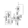
- FIG. 1 is a block diagram showing an outline of a digital camera connected to a computer.
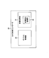
- FIG. 2 is a block diagram illustrating a functional configuration example of the camera body controller.
- FIG. 3 is a diagram showing an outline from image shooting to point image restoration processing.
- FIG. 4 is a block diagram illustrating an outline of an example of the point image restoration process.
- FIG. 5 is a diagram showing an example of the contrast change of the edge portion in the subject image when ideal point image restoration processing (no pixel value saturation and no clipping) is performed, and (a) shows the subject image.
- (B) shows the contrast in the original image data before the point image restoration process
- (c) shows the contrast in the restored image data after the point image restoration process.
- FIG. 1 is a block diagram showing an outline of a digital camera connected to a computer.
- FIG. 2 is a block diagram illustrating a functional configuration example of the camera body controller.
- FIG. 3 is a diagram showing an outline from image shooting to point image restoration processing.
- FIG. 6 is a diagram showing an example of the contrast change of the edge portion in the subject image in the actual point image restoration processing (with pixel value saturation and clipping).
- FIG. 6A shows the contrast inherent in the subject image.
- (B) shows the contrast in the original image data before the point image restoration process, and
- (c) shows the contrast in the restored image data after the point image restoration process.
- FIG. 7A is a block diagram illustrating various image processing flows in the image processing unit (camera body controller).
- FIG. 7B is another block diagram illustrating various image processing flows in the image processing unit (camera body controller).
- FIG. 7C is another block diagram illustrating various image processing flows in the image processing unit (camera body controller).
- FIG. 7D is another block diagram illustrating various image processing flows in the image processing unit (camera body controller).
- FIG. 7A is a block diagram illustrating various image processing flows in the image processing unit (camera body controller).
- FIG. 7B is another block diagram illustrating various image processing flows in the image processing unit (
- FIG. 8 is a diagram showing a correlation between “tone correction processing (gamma correction processing)” and “color data / luminance data” with respect to the point image restoration processing.
- FIG. 9 is a diagram for explaining an overshoot generation mechanism by point image restoration processing.
- FIG. 10 is a diagram illustrating an example of a relationship between pre-processing data and post-processing data by gamma processing (logarithmization processing).
- FIG. 11 is a diagram illustrating an image processing block according to the first embodiment.
- FIG. 12 is a diagram showing a point image restoration processing flow by the image processing block shown in FIG.
- FIG. 13 is a diagram illustrating an image processing block according to a modification of the first embodiment.
- FIG. 14 is a diagram illustrating an image processing block according to another modification of the first embodiment.
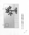
- FIG. 15 is a diagram showing an image example (original image data) for explaining an example of determining the presence or absence of the point image restoration process for each pixel data, and the target pixel in the kernel (Km, Kn) and its surroundings An example in which determination is performed based on image analysis data (image information) of pixels will be shown.
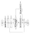
- FIG. 16 is a diagram illustrating an example of a point image restoration processing flow according to the second embodiment.
- FIG. 17 is a diagram illustrating an example of an image processing block according to the third embodiment.
- FIG. 18A is a graph illustrating the “spatial frequency-amplitude” relationship of the restoration filter, and shows an example of the characteristics of the filter (filter A) used in normal point image restoration processing.
- FIG. 18B is a graph illustrating the “spatial frequency-amplitude” relationship of the restoration filter, and shows an example of the characteristics of the anti-ringing restoration filter (filter B).
- FIG. 19 is a diagram showing a point image restoration processing flow by the image processing block shown in FIG.
- FIG. 20 is a diagram illustrating an example of an image processing block according to the fourth embodiment.
- FIG. 21 is a diagram showing a point image restoration processing flow by the image processing block shown in FIG.
- FIG. 22 is a diagram illustrating a modification of the image processing block according to the fourth embodiment.
- FIG. 23 is a diagram illustrating an example of an image processing block according to the fifth embodiment.
- FIG. 24 is a diagram showing a point image restoration processing flow by the image processing block shown in FIG. FIG.
- FIG. 25 is a block diagram illustrating an embodiment of an imaging module including an EDoF optical system.
- FIG. 26 is a diagram illustrating an example of an EDoF optical system.
- FIG. 27 is a diagram showing an example of a restoration processing flow by the restoration processing block shown in FIG.
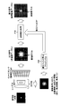
- FIG. 28 is a diagram showing an example of restoration of an image acquired via the EDoF optical system, where (a) shows a blurred image before the restoration process, and (b) shows that the blur after the restoration process has been eliminated. An image (point image) is shown.
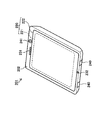
- FIG. 29 is an external view of a smartphone.
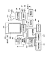
- FIG. 30 is a block diagram showing a configuration of the smartphone shown in FIG.
- FIG. 1 is a block diagram showing an outline of a digital camera connected to a computer.
- the digital camera 10 includes a replaceable lens unit 12 and a camera body 14 having an image sensor 26, and the lens unit 12 has a lens unit input / output unit 22 and a camera body input / output unit 30 of the camera body 14.
- the lens unit 12 and the camera body 14 are electrically connected.
- the lens unit 12 includes an optical system such as a lens 16 and a diaphragm 17 and an optical system operation unit 18 that controls the optical system.
- the optical system operation unit 18 is a lens connected to the lens unit input / output unit 22.
- a unit controller 20 and an actuator (not shown) for operating the optical system are included.
- the lens unit controller 20 controls the optical system via an actuator based on a control signal sent from the camera body 14 via the lens unit input / output unit 22, for example, focus control or zoom control by lens movement, aperture 17 aperture amount control and the like are performed.
- the imaging device 26 of the camera body 14 includes a condensing microlens, a color filter such as RGB, and an image sensor (photodiode; CMOS (Complementary Metal Oxide Semiconductor), CCD (Charge Coupled Device), etc.), and a lens unit.
- CMOS Complementary Metal Oxide Semiconductor
- CCD Charge Coupled Device
- the light of the subject image irradiated through the twelve optical systems (lens 16, aperture 17, etc.) is converted into an electrical signal, and the image signal (original image data) is sent to the camera body controller 28.
- the image sensor 26 of this example outputs original image data by photographing a subject image using an optical system, and this original image data is transmitted to the image processing device of the camera body controller 28.
- the camera body controller 28 controls the camera body 14 in an integrated manner, and includes a device control unit 34 and an image processing unit (image processing device) 35 as shown in FIG.
- the device control unit 34 controls the output of an image signal (image data) from the image sensor 26 or generates a control signal for controlling the lens unit 12 and the lens via the camera body input / output unit 30.
- the device control unit 34 appropriately controls various devices included in the digital camera 10 such as a display unit (EVF: Electronic View Finder, rear liquid crystal display unit) (not shown).
- EMF Electronic View Finder, rear liquid crystal display unit
- the image processing unit 35 can perform arbitrary image processing on the image signal from the image sensor 26 as necessary. For example, sensor correction processing, demosaicing (synchronization) processing, pixel interpolation processing, color correction processing (offset correction processing, white balance processing, color matrix processing, gamma conversion processing, etc.), RGB image processing (sharpness processing, tone correction processing) , Exposure correction processing, contour correction processing, etc.), RGB / YCrCb conversion processing, image compression processing, and other various types of image processing are appropriately performed in the image processing unit 35.
- the image processing unit 35 of this example includes a point image restoration processing unit 36 that performs a so-called point image restoration process on the image signal (original image data). Details of the point image restoration process will be described later.
- the image data processed by the camera body controller 28 is sent to a computer 60 or the like connected to the input / output interface 32.
- the format of the image data sent from the digital camera 10 (camera body controller 28) to the computer 60 or the like is not particularly limited, and may be any format such as RAW, JPEG, TIFF, and the like. Therefore, the camera main body controller 28, like so-called Exif (Exchangeable Image File Format), includes a plurality of header information (shooting information (shooting date and time, model, number of pixels, aperture value, etc.)), main image data, thumbnail image data, and the like.
- the related data may be associated with each other to form one image file, and the image file may be transmitted to the computer 60.
- the computer 60 is connected to the digital camera 10 via the input / output interface 32 and the computer input / output unit 62 of the camera body 14 and receives data such as image data sent from the camera body 14.
- the computer controller 64 controls the computer 60 in an integrated manner, performs image processing on image data from the digital camera 10, and is connected to the computer input / output unit 62 via a network line such as the Internet 70. Control communication.
- the computer 60 has a display 66, and the processing contents in the computer controller 64 are displayed on the display 66 as necessary.
- the user operates the input means (not shown) such as a keyboard while confirming the display on the display 66 to input data and commands to the computer controller 64 to control the computer 60 or connect to the computer 60. And the like (digital camera 10, server 80) can be controlled.
- the server 80 includes a server input / output unit 82 and a server controller 84.
- the server input / output unit 82 constitutes a transmission / reception connection unit with external devices such as the computer 60, and is connected to the computer input / output unit 62 of the computer 60 via a network line such as the Internet 70.
- the server controller 84 cooperates with the computer controller 64 in response to a control instruction signal from the computer 60, transmits and receives data to and from the computer controller 64 as necessary, and downloads data to the computer 60. Then, an arithmetic process is performed and the calculation result is transmitted to the computer 60.
- Each controller (the lens unit controller 20, the camera body controller 28, the computer controller 64, and the server controller 84) includes circuits necessary for control processing, such as an arithmetic processing circuit (CPU or the like), a memory, or the like.
- Communication between the digital camera 10, the computer 60, and the server 80 may be wired or wireless.
- the computer 60 and the server 80 may be configured integrally, and the computer 60 and / or the server 80 may be omitted.
- the digital camera 10 may be provided with a communication function with the server 80, and data may be directly transmitted and received between the digital camera 10 and the server 80.
- the program according to the embodiment of the present invention is a non-temporary recording such as various magneto-optical recording media and semiconductor recording media provided in the image processing unit 35, the computer 60, or the storage unit 250 of the smartphone 201 described later. It can be used by recording on a medium.
- a restoration process using a restoration filter based on the point spread function of the optical system is performed on the original image data acquired from the image sensor 26 by photographing using the optical system (lens 16, aperture 17, etc.). This is a process of performing recovery image data acquisition.
- FIG. 3 is a diagram showing an outline from image shooting to point image restoration processing.
- the subject image is received by the image sensor 26 (image sensor) via an optical system (lens 16, aperture 17, etc.), and original image data Do is output from the image sensor 26.
- the original image data Do is image data in a state where the original subject image is blurred due to the point spread phenomenon derived from the characteristics of the optical system.
- a point image restoration process P10 using the restoration filter F is performed on the original image data Do, whereby the original subject image ( Recovered image data Dr representing an image (recovered image) closer to the point image) is obtained.
- the restoration filter F used in the point image restoration processing P10 is obtained by the restoration filter calculation algorithm P20 from the point image information (point spread function) of the optical system according to the photographing conditions at the time of acquiring the original image data Do.
- the point image information (point spread function) of the optical system can vary depending not only on the type of the lens 16 but also on various photographing conditions such as the aperture amount, focal length, zoom amount, image height, number of recorded pixels, pixel pitch, and the like. When calculating the restoration filter F, these photographing conditions are acquired.
- FIG. 4 is a block diagram showing an outline of an example of the point image restoration process.
- the point image restoration process P10 is a process for creating the restored image data Dr from the original image data Do by the filtering process using the restoration filter F.
- N ⁇ M N and M are integers of 2 or more
- the restoration filter F in the real space constituted by the taps is applied to the image data to be processed.
- the weighted average calculation (deconvolution calculation) of the filter coefficient assigned to each tap and the corresponding pixel data (processing target pixel data of the original image data Do and adjacent pixel data) is performed, so that Pixel data (recovered image data Dr) can be calculated.
- the point image restoration process can be performed by applying the weighted average process using the restoration filter F to all the pixel data constituting the image data by changing the target pixel in order.
- the restoration filter in the real space constituted by N ⁇ M taps can be derived by performing inverse Fourier transform on the restoration filter in the frequency space. Therefore, the restoration filter in the real space can be appropriately calculated by specifying the restoration filter in the basic frequency space and designating the number of constituent taps of the restoration filter in the real space.
- FIG. 5 and FIG. 6 are diagrams showing an example of a change in image quality of an edge portion (image boundary portion) in a subject image.
- FIG. 5 shows an ideal point image restoration process (no pixel value saturation, no clipping).
- FIG. 6 shows an example of actual point image restoration processing (with pixel value saturation and clipping).
- FIGS. 5A and 6A show the contrast inherent in the subject image
- FIGS. 5B and 6B show the contrast in the original image data Do before the point image restoration processing
- 5 (c) and FIG. 6 (c) show the contrast in the recovered image data Dr after the point image restoration processing.
- the horizontal direction (X direction) indicates a position (one-dimensional position) in the subject image
- the vertical direction (Y direction) indicates contrast strength.
- the “edge portion having a contrast step” in the subject image is a captured image (original image) due to the point spread phenomenon of the optical system at the time of shooting.
- Image blur occurs in the image data Do (see FIGS. 5B and 6B), and the restored image data Dr is obtained by the point image restoration process (FIG. 5C and FIG. 6B). c)).
- the original image data including a pixel (saturated pixel) with a saturated pixel value is in a state where it is clipped at the saturated pixel portion (see FIG. 6).
- the contrast change is relatively clear, resulting in degradation (image blur).
- deviation from the original image data (subject image) occurs due to clipping of the pixel data.
- restoration processing using a normal restoration filter is performed on the original image data in which such data deviation occurs, ringing is likely to occur and the generated ringing is likely to be complicated (see FIG. 6C). .
- high frequency components increase, and aliasing noise tends to be emphasized.
- FIG. 7A to 7D are block diagrams illustrating various image processing flows in the image processing unit 35 (camera body controller 28).
- FIG. 7A shows an example in which point image restoration processing is performed on luminance data (Y) after gamma correction processing (tone correction processing)
- FIG. 7B shows point image restoration on RGB color data after gamma correction processing.
- An example of processing is shown.
- 7C shows an example in which point image restoration processing is performed on RGB color data before gamma correction processing
- FIG. 7D is an example in which point image restoration processing is performed on luminance data (Y) before gamma correction processing. Indicates.
- the image processing unit 35 “offset correction processing 41 for adjusting image brightness” and “image white balance (WB)”.
- WB correction processing 42 “ demosaic processing 43 for acquiring color data of each RGB color for all pixels by pixel interpolation processing ”,“ tone correction by logarithmic processing is performed to adjust the gradation of pixel data
- Gamma correction processing (gradation correction step; gradation correction unit) 44 ”,“ luminance / color difference conversion processing 45 for calculating luminance data (Y) and color difference data (Cb / Cr) from RGB color data ”and“ image data
- Point image restoration processing (restoration processing step) for performing point image restoration processing using a restoration filter based on the point spread function of the optical system used for photographing Sequentially performed 46 ".
- the color data corresponds to the color type of the color filter of the image sensor 26 that has acquired and acquired mosaic data (original image data), and the luminance data and the color
- the processing order of the luminance / color difference conversion processing 45 and the point image restoration processing 46 in the image processing example of FIG. 7A is switched. Therefore, in the example of FIG. 7A, the point image restoration process 46 is performed on the luminance data of the original image data after the gamma correction process (gradation correction) 44, but in the example of FIG. 7B, the gamma correction process (gradation correction) is performed. ) The point image restoration processing 46 for the RGB color data of the original image data 44 is performed by the point image restoration processing unit 36, and thereafter the luminance data and the color difference data are calculated.
- the processing order of the gamma correction processing 44 and the point image restoration processing 46 in the image processing example of FIG. 7B is switched.
- the point image restoration process 46 is performed after the gamma correction process 44, whereas the point image restoration process 46 is performed before the gamma correction process 44 in the example shown in FIG. 7C.
- the offset correction process 41, the WB correction process 42, and the demosaic process 43 are the same as the examples of FIGS. 7A to 7D, but after the demosaic process 43, the luminance / color difference conversion process 45a is performed. After the point image restoration process 46 is performed, a color signal conversion process 47 for calculating RGB color data from the luminance data and the color difference data is performed. Then, the gamma correction process 44 and the brightness / color difference conversion process 45b are sequentially performed on the RGB color data, whereby the brightness data and the color difference data are acquired.
- FIGS. 7A to 7D is merely an example of a processing flow, and other processing may be performed at an arbitrary stage as necessary, or a part of the processing illustrated in FIGS. 7A to 7D may be performed. It may be omitted.
- FIG. 8 is a diagram showing the correlation between “tone correction processing (gamma correction processing)” and “color data / luminance data” with respect to the point image restoration processing.
- the column indicated by “true number (before gradation correction)” in FIG. 8 is an image when point image restoration processing is performed on image data (true number image data) before gradation correction processing (gamma correction processing).
- the column indicating the characteristics (see FIGS. 7C and 7D) and “logarithm (after gradation correction)” is a point image restoration process for the image data (logarithmic image data) after the gradation correction process (gamma correction process).
- FIG. 7A and FIG. 7B show image characteristics when performing the above.
- the column indicated by “color data (RGB)” in FIG. 8 indicates image characteristics when the point image restoration process is performed on the color data (RGB data) (see FIGS. 7B and 7C).
- the column indicated by (Y) indicates image characteristics when the point image restoration process is performed on the luminance data (see FIGS. 7A and 7D).
- the ideal system here refers to “the number of filter taps of the restoration filter used in the point image restoration process is sufficiently large”, “the number of calculation bits is sufficiently large”, “actual blur characteristics of the optical system and image processing Appropriate point image restoration processing is performed, such as “the optical system blur characteristic data held by the unit 35 coincides with” or “saturated pixel data with saturated pixel values does not include input image data (original image data)”. It refers to an ideal system in which the conditions are sufficiently satisfied.
- the point image restoration of logarithmic image data is more efficient than the point image restoration of true number image data (image data before gradation correction).
- the present inventor confirmed that the appearance of side effects such as ringing in the point image restoration image (recovery image) is small by a plurality of experiments ("Luminance system toughness in a system deviating from the ideal system ( Ringing degree, etc.) ”)).
- FIG. 9 is a diagram for explaining an overshoot occurrence mechanism by point image restoration processing.
- the horizontal direction (X direction) indicates a position (one-dimensional position) in the image
- the vertical direction (Y direction) indicates a pixel value.
- An image edge portion (see FIG. 9A) whose image quality has deteriorated due to the point spread phenomenon of the optical system (see FIG. 9A) approaches the original image quality (contrast) by the point image restoration process, but is so-called overshoot (undershoot). May occur (see FIG. 9B). If the overshoot caused by the point image restoration process itself is small, it is not particularly noticeable visually, but if the gradation correction process (gamma correction process) is performed thereafter, the overshoot may be emphasized more than necessary. (Refer to “E1” and “E2” in FIG. 9C).
- the overshoot (undershoot) portion on the shadow side is applied with a large gain (amplification factor) by the subsequent gamma correction processing, and constitutes a portion that is largely biased to the black side in the image edge portion (FIG. 9). (See “E2” in (c)).
- This phenomenon is not limited to the point image restoration process, and is common even when an overshoot occurs in the edge portion as a result of the contour correction process performed on the image data in the true space.
- point image restoration processing for color data is a point image of color data (color signal) of each color of RGB as expected (according to retained deterioration information (point spread function information of the optical system)). If input to the restoration processing unit 36, effective color data correction can be performed, and chromatic aberration can be effectively reduced as compared with “point image restoration processing for luminance data (Y data)”. (See “Restorability in an ideal system” and “Color system correction capability” in FIG. 8). However, when the behavior of the actual input signal is not as expected, the point image restoration process for color data (RGB data) may cause side effects such as an increase in the number of places where unnecessary coloring occurs and an unnatural hue. (Refer to “Color system toughness in a system deviated from the ideal system (colored degree, degree of bleeding, etc.)” in FIG. 8).
- the processing scale (the scale of the processing circuit when the processing system is hardware) is different as shown in FIG. That is, the point image restoration processing of logarithmic image data (image data in logarithmic space) is simpler than arithmetic processing, and the processing scale is smaller than that of true image data (image data in the logarithmic space). Is advantageous. Further, the point image restoration process for color data (RGB data) requires a processing system for three channels (3 ch), but the point image restoration process for luminance data (Y data) requires processing for one channel (1 ch). Since the system is sufficient, the point image restoration process for luminance data is simpler in arithmetic processing, and the processing scale can be made compact.
- an appropriate system according to the user's needs is constructed based on the above-described various characteristics shown in FIG. For example, “Various types of input image signals (image data) are input”, “Make the processing system as small as possible”, “Actual image degradation information and processing system If the processing conditions deviate from the ideal processing system, such as "There is no guarantee that the stored image degradation information is in perfect agreement", point image restoration processing for logarithmic image data is better for point image restoration for true image data. It is more excellent in image toughness (image non-destructiveness) than processing.
- the point image restoration process is performed after the gradation correction process (gamma correction process).
- gradation correction process gamma correction process
- an image processing system that performs point image restoration processing on luminance data is preferable to color data, but color reproducibility is improved. If importance is attached, an image processing system that performs point image restoration processing on color data is preferable to luminance data.
- the restoration filter when performing gradation correction by logarithmic processing (gamma correction processing), the restoration filter itself may be composed of filter coefficients corresponding to image data before logarithmic processing, or image data after logarithmic processing. It may consist of filter coefficients corresponding to.
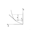
- FIG. 10 is a diagram (graph) illustrating an example of a relationship between pre-processing data and post-processing data by gamma processing (logarithmization processing).
- the horizontal axis of FIG. 10 represents pre-processing data (gamma processing input data “IN”), the vertical axis represents post-processing data (gamma processing output data “OUT”), and the solid line in the graph represents the gamma processing gradation curve. Show.
- point image restoration processing is performed on pixel data (pixel data before gradation correction) whose pixel value is a true number in an area including a saturated pixel in a high contrast area, and then gradation correction (gamma) is performed.
- gradation correction gamma
- undershoot / overshoot ringing
- the point image restoration process is performed on the pixel data after the logarithmization process, high contrast is compressed by the logarithmization process, and the intensity of ringing by the point image restoration process is reduced.
- the pixel data after logarithmic processing is generally visually recognized by performing restoration processing (point image restoration processing) using a restoration filter composed of filter coefficients corresponding to pixel data having a true pixel value. While it is possible to perform point image restoration processing on the low-contrast region that is likely to be inferior, it is possible to reduce the degree of ringing enhancement in the high-contrast region where ringing is likely to occur due to the point image restoration processing.
- an image processing apparatus such as an imaging apparatus
- a plurality of types of gradation correction gamma correction processing
- Patent Document 3 it is necessary to calculate a limit value for the amount of change in pixel signal value for each of a plurality of types of gradation correction.
- point image restoration processing is applied to pixel data after gradation correction, switching of processing according to the type of gradation correction becomes unnecessary.
- PSF point spread function
- the pixel value (logarithmic pixel data) after gradation correction (logarithmic processing) is restored using a restoration filter composed of filter coefficients corresponding to the pixel value after logarithmic processing (logarithmic pixel data).
- the point image restoration process itself can be performed accurately.
- the target image data of the point image restoration process to “original image data after gradation correction”
- high contrast is compressed by gradation correction (logarithmization processing)
- ringing generated by the point image restoration process The strength of can be reduced.
- the restoration filter used in the point image restoration process may be generated in advance, or may be sequentially calculated and generated in accordance with the execution of the point image restoration process. From the viewpoint of reducing the amount of calculation during the point image restoration process, it is preferable to generate a restoration filter in advance. Further, from the viewpoint of using a restoration filter with excellent adaptability, it is preferable to sequentially calculate the restoration filter when the point image restoration process is executed.
- the filter coefficient of the restoration filter is obtained by performing an operation based on the pixel value obtained by the logarithmic process (gamma correction process) on the input pixel value (input image data).
- the pixel value used for generating the restoration filter may be a luminance value, or may be a pixel value (for example, G pixel value) related to one channel that is typically selected from the RGB color data.
- the pixel value used for generating the restoration filter may be a pixel value of the main subject or a pixel value obtained from an average value of the entire screen.
- the point image restoration processing may be processing that restores only the amplitude component of the original image data to obtain restored image data, or obtains restored image data by restoring the amplitude component and phase component of the original image data. It may be a process. That is, the restoration filter can be calculated based on at least one of the MTF (Modulation Transfer Function) / PTF (Phase Transfer Function) of the optical system.
- the blur characteristic of the optical system can be expressed by a so-called optical transfer function (OTF), and the function obtained by inverse Fourier transform of the OTF is a point spread function (PSF: Point Spread Function: point spread). It is also called a function.
- MTF is an absolute value component of OTF
- PTF represents a phase shift as a function of spatial frequency. Therefore, the restoration filter used for the point image restoration process can be appropriately designed based on the OTF (MTF / PTF) or PSF of the optical system.
- the target of the point image restoration process is “image data before gradation correction” and “image data after gradation correction”. Which of these may be determined.
- image unit depends on whether or not “image information related to an image (original image data) to be subjected to point image restoration processing” corresponds to “a condition for causing ringing in the restored image data by point image restoration processing”.
- the image processing is controlled to determine whether or not to execute the point image restoration processing.
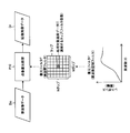
- FIG. 11 is a diagram showing an image processing block according to the first embodiment.
- the image processing unit 35 (see FIG. 2) of this embodiment includes an image analysis unit 37, a ringing determination unit 38, and a restoration processing determination unit (processing control unit) in addition to the point image restoration processing unit (restoration processing unit) 36. 39.
- the image processing blocks in the figure are not necessarily provided separately, and may be realized by hardware / software that integrally configures a plurality of image processing blocks.
- the image analysis unit 37 analyzes the original image data acquired from the image sensor by photographing using the optical system, and acquires image analysis data (image information). In this example, whether or not saturated pixels are included in the original image data is acquired by analysis of the original image data in the image analysis unit 37.
- the image analysis result of the image analysis unit 37 is sent to the ringing determination unit 38 as image analysis data.
- the ringing determination unit 38 determines whether or not the image analysis data sent from the image analysis unit 37 corresponds to “a condition for causing ringing in the recovered image data by the point image restoration process (ringing occurrence condition)”. Specifically, when the image analysis data indicates that the original image data includes saturated pixels, the ringing determination unit 38 determines that “the image analysis data corresponds to the ringing occurrence condition”. On the other hand, when the image analysis data indicates that the original image data does not include saturated pixels, the ringing determination unit 38 determines that “the image analysis data does not correspond to the ringing occurrence condition”. As described above, the ringing determination unit 38 determines the possibility of ringing in the recovered image data.
- the possibility of ringing may indicate not only “the presence or absence of ringing” but also “whether or not ringing that stands out by visual recognition occurs”. Therefore, for example, when ringing does not occur at all or when ringing that is not noticeable by visual recognition does not occur, “ringing is not likely to occur (low)”, and when ringing occurs or ringing that is noticeable by visual recognition occurs. The possibility of ringing is high.
- the determination result in the ringing determination unit 38 is sent to the restoration processing determination unit 39 as ringing determination data.
- the restoration processing determination unit 39 controls image processing based on the determination result of the ringing determination unit 38 and determines whether or not the point image restoration processing in the point image restoration processing unit 36 is performed.
- the restoration processing determination unit 39 sends the original image data to the point image restoration processing unit 36.
- the restoration processing determination unit 39 skips the point image restoration processing unit 36 and sends the original image data to the subsequent processing unit.
- the restoration processing determination unit 39 of this example controls the point image restoration processing (image processing) for each original image data.
- the point image restoration processing unit 36 performs restoration processing using a restoration filter based on a point spread function of the optical system on the original image data to obtain restored image data.
- the restoration processing determination unit 39 and the point image restoration processing unit 36 are provided in the subsequent stage of the gamma correction processing unit (see the gamma correction processing 44 in FIGS. 7A to 7D), and the point image restoration processing in the point image restoration processing unit 36 is performed as follows. This is performed on the original image data after the gamma correction processing (after gradation correction) (see FIGS. 7A and 7B).
- the original image data before the gamma correction process may be input to the image analysis unit 37, or the original image data after the gamma correction process may be input.
- Image analysis data may be generated.
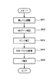
- FIG. 12 is a diagram showing a point image restoration processing flow by the image processing block shown in FIG.
- the original image data is analyzed in the image analysis unit 37, and it is checked whether or not the original image data includes saturated pixels (S1 in FIG. 12; image information acquisition step).
- the ringing determination unit 38 determines that the possibility of ringing occurring in the recovered image data is not high (low) (N in S2; ringing determination step). In this case, the original image data is sent from the restoration processing determination unit 39 to the point image restoration processing unit 36, and the point image restoration processing unit 36 performs point image restoration processing to obtain restored image data (S3). The image data is sent to the subsequent processing unit.
- the ringing determination unit 38 determines that ringing is likely to occur in the recovered image data (Y in S2).
- the image restoration processing unit 36) is skipped (S4), and the original image data is sent to the subsequent processing unit.
- the execution of the point image restoration process is determined depending on whether or not saturated pixels are included in the original image data, but the present invention is not limited to this.
- an image indicating whether or not the original image data includes pixel data having a pixel value larger than a threshold value for example, 90% of a saturated pixel value (the maximum pixel value that can be permitted by the constituent pixels of the image sensor 26)
- Analysis data may be generated in the image analysis unit 37.
- the ringing determination unit 38 determines that the possibility of ringing is high, and the restoration processing determination unit 39 performs point image restoration processing ( The point image restoration processing unit 36) is skipped, and the original image data is sent to the subsequent processing unit.
- the ringing determination unit 38 determines that the possibility of ringing is not high (low), and the restoration processing determination unit 39
- the original image data is sent to the restoration processing unit 36, and the point image restoration processing unit 36 performs point image restoration processing of the original image data.
- the possibility of ringing is determined based on whether or not pixel data having saturated pixel values or pixel data having a pixel value larger than a threshold is included in the original image data by a predetermined number of pixels or more. May be determined.
- image analysis data acquired by analyzing original image data is used as image information that is the basis of ringing determination. It is also possible to use “image acquisition condition data” as this image information.
- FIG. 13 is a diagram illustrating an image processing block according to a modification of the first embodiment.
- the image processing unit 35 (see FIG. 2) of this modification includes an image acquisition condition acquisition unit 40 instead of the image analysis unit 37 of FIG.
- the image acquisition condition acquisition unit 40 acquires the acquisition conditions of the original image data, and sends image acquisition condition data indicating the original image data acquisition conditions to the ringing determination unit 38.
- the ringing determination unit 38 determines whether or not the image acquisition condition data satisfies the ringing occurrence condition in the recovered image data by the restoration process.
- the “original image data acquisition condition (image acquisition condition data)” acquired by the image acquisition condition acquisition unit 40 of the present modification includes information on the optical system used for capturing the original image data, and is a point image restoration.
- Various elements that can affect the restoration accuracy of the process and the side effects (ringing, etc.) of the restoration process can be included in the “original image data acquisition condition (image acquisition condition data)”.
- the optical system information here includes at least one of a lens type, an aperture value, and a zoom value of the optical system used for photographing to acquire original image data.
- the “image acquisition condition data acquisition method in the image analysis unit 37” and the “ringing determination method in the ringing determination unit 38” are not particularly limited.
- a “condition that ringing is highly likely to occur in the recovered image data” is determined in advance and held by the ringing determination unit 38, and depending on whether or not the image acquisition condition data satisfies the held condition, The possibility of occurrence may be determined.
- a “highly likely condition of ringing” is defined for each type of optical system (lens model number, etc.). Also good.
- the image acquisition condition acquisition unit 40 may acquire the image acquisition condition data together with the original image data.
- the image acquisition condition acquisition unit 40 may access the memory and acquire the image acquisition condition data.
- FIG. 14 is a diagram illustrating an image processing block according to another modification of the first embodiment.
- the image processing unit 35 (see FIG. 2) of the present modification includes an image information acquisition unit 48 including an image analysis unit 37 in FIG. 11 and an image acquisition condition acquisition unit 40 in FIG.
- the image information acquisition unit 48 including the image analysis unit 37 and the image acquisition condition acquisition unit 40 acquires image information including at least one of the above-described image analysis data and image acquisition condition data.
- This image information is sent as image information data from the image information acquisition unit 48 to the ringing determination unit 38.
- the ringing determination unit 38 determines whether the image information satisfies the ringing occurrence condition in the recovered image data by the restoration process.
- the restoration processing determination unit 39 and the point image restoration processing unit 36 of the present modification are the same as those in the above-described embodiment (see FIGS. 11 and 12) and the modification (see FIG. 13).
- point image restoration processing is performed on an image (image data) that can be expected to improve image quality by applying point image restoration processing.
- the point image restoration process is not performed on an image that is predicted to have a high probability that image quality deterioration such as ringing is conspicuous due to the point image restoration process.
- image data including ringing is prevented from being sent to the subsequent stage, and a captured image (image data) with degraded image quality is obtained by the user. Can be prevented from being offered to.
- an image is obtained in units of “pixels” depending on whether or not “image information related to an image (original image data) subject to point image restoration processing” corresponds to “a condition for causing ringing in the restored image data by the point image restoration processing”. Processing is controlled.
- the point image restoration process is controlled for each original image data in “image” units, but in this embodiment, the point image restoration process is performed for each pixel data in “pixel” units. Is controlled.
- FIG. 15 is a diagram showing an image example (original image data) for explaining an example of determining the presence or absence of the point image restoration process for each pixel data, and the target pixel in the kernel (Km, Kn) and its surroundings An example in which determination is performed based on image analysis data (image information) of pixels will be shown.
- the image processing unit 35 (see FIG. 2) of the present example has an image processing block similar to the image processing block shown in FIG. 11, and the image analysis unit 37 analyzes the original image data and determines from the saturated pixel data or the threshold value. Image analysis data (image information) indicating whether or not pixel data having a larger pixel value is included in the original image data is acquired.
- the ringing determination unit 38 determines the possibility of ringing based on the image analysis data sent from the image analysis unit 37, but performs determination for each pixel data of the original image data.
- the ringing determination unit 38 performs point image restoration for the target pixel for each pixel data constituting the original image data based on the image analysis data (image information) regarding the target pixel in the original image data and the peripheral pixels of the target pixel. It is determined whether or not ringing is likely to occur due to the processing.
- the target pixel arranged at the center in a kernel of a predetermined size for example, a kernel of about 9 pixels (X direction) ⁇ 9 pixels (Y direction) (see “Km” and “Kn” in FIG. 15)
- a kernel of about 9 pixels (X direction) ⁇ 9 pixels (Y direction) for example, a kernel of about 9 pixels (X direction) ⁇ 9 pixels (Y direction) (see “Km” and “Kn” in FIG. 15)
- It is ringing whether or not at least a part of the pixel data of the peripheral pixels arranged around the pixel data is saturated pixel data (saturated pixel data) or pixel data having a pixel value larger than a threshold value.
- the determination unit 38 determines.
- the size of the kernel is not particularly limited, but the size of the restoration filter (restoration filter in real space) used for the point image restoration processing (“N tap” of “real space filter” in FIG. 4 and It is desirable that the kernel size is set to be equal to or smaller than the size of the real space filter used for the point image restoration process.
- the ringing determination unit 38 determines whether the pixel of interest In the image restoration process, it is determined that the possibility of ringing is high. On the other hand, when it is determined that the pixel data in the kernel does not include “saturated pixel data or pixel data having a pixel value larger than the threshold” (see “Km” in FIG. 12), the ringing determination unit 38 In the point image restoration processing of the pixel, it is determined that the possibility of ringing is not high (low).
- the “ringing occurrence possibility determination result” obtained for each pixel data of the original image data in this way is sent from the ringing determination unit 38 to the restoration processing determination unit 39 as ringing determination data.
- the restoration processing determination unit (processing control unit) 39 controls the point image restoration processing for each pixel data constituting the original image data. That is, the restoration processing determination unit 39 cooperates with the point image restoration processing unit 36 based on the ringing determination data, and executes / does not execute the point image restoration processing for each pixel data while changing the target pixel in the original image data. Is done. That is, point image restoration processing is performed on “pixel data determined that ringing is not likely (low)”, while “pixel data determined that ringing is highly likely”. On the other hand, the restoration processing determination unit 39 controls the point image restoration processing unit 36 so that the point image restoration processing is not performed.
- FIG. 16 is a diagram illustrating an example of a point image restoration processing flow according to the second embodiment.
- FIG. 16 shows an example in which the presence / absence of the point image restoration process (possibility of ringing) is determined based on the presence / absence of saturated pixel data.
- the original image data is analyzed, and image analysis data (image information) indicating whether the saturated pixel data is included in the original image data is acquired by the image analysis unit 37 (S11 in FIG. 16). Is sent to the ringing determination unit 38. Then, for each pixel data constituting the original image data, the “ringing determination unit 38 determines whether or not there is a high possibility of ringing in the recovered image data due to the point image restoration process”. It is sent to the determination unit 39.
- the restoration processing determination unit 39 determines whether or not the possibility of occurrence of ringing is high by the point image restoration processing for the I-th pixel (target pixel) (S14).
- the possibility of ringing is not high (low) (N in S14)
- the restoration process determination unit 39 determines not to perform the point image restoration process for the I-th pixel (S16).
- the point image restoration process is executed for all the pixels constituting the original image data. Presence or absence is determined. Therefore, based on this determination result, the point image restoration process by the point image restoration processing unit 36 is executed / not executed for each pixel data of the original image data.
- point image restoration processing is performed on pixels (pixel data) that can be expected to improve image quality by applying point image restoration processing, and side effects such as ringing are conspicuous.
- Point image restoration processing is not performed on such pixels (pixel data). In this way, whether or not the point image restoration process is performed in units of pixels is switched, and the point image restoration process can be performed only on pixels (pixel data) that can be expected to improve image quality by the point image restoration process. Image quality can be improved.
- pixels that are subjected to point image restoration processing and “pixels that are not subjected to point image restoration processing” are mixed in one restoration image (recovery image data). Even in the case where “restored pixels” and “non-point-restored pixels” coexist in the restored image, the restoration reproducibility between both pixels is sufficiently balanced on the user's vision. It has been confirmed by experiments by the present inventors that the image quality is good as a whole.
- the restoration filter used in the point image restoration process is switched / selected based on at least one of image analysis data and image acquisition condition data.
- the restoration filter is switched in units of images (original image data) based on information (image analysis data) whether or not the original image data includes saturated pixels.
- FIG. 17 is a diagram illustrating an example of an image processing block according to the third embodiment.
- the image processing unit 35 (see FIG. 2) of the present embodiment includes an image analysis unit 37, a ringing determination unit 38, a filter selection unit (processing control unit) 55, and a point image restoration processing unit 36.
- the image analysis unit 37 and the ringing determination unit 38 are the same as those in the above-described embodiment. That is, the image analysis unit 37 analyzes the original image data to obtain image analysis data, and the ringing determination unit 38 determines the possibility of ringing. In this example, whether or not saturated pixels are included in the original image data is analyzed by the image analysis unit 37, and the possibility of occurrence of ringing is determined for each original image data in units of images by the ringing determination unit 38.
- the filter selection unit 55 determines a restoration filter to be used in the point image restoration process of the point image restoration processing unit 36 based on the determination result (ringing determination data) of the ringing determination unit 38. That is, a normal restoration filter is selected by the filter selection unit 55 for an image (original image data) determined that the possibility of ringing is not high (low). On the other hand, for an image (original image data) determined to have a high possibility of ringing, it is not a normal restoration filter, but a restoration filter that suppresses the occurrence of ringing / does not emphasize ringing (ringing countermeasure restoration filter). Is selected by the filter selection unit 55.
- FIGS. 18A and 18B are graphs illustrating the “spatial frequency-amplitude” relationship of the restoration filter.
- FIG. 18A shows an example of characteristics of a filter (filter A) used in normal point image restoration processing
- FIG. 18B shows an example of characteristics of a ringing countermeasure restoration filter (filter B).
- filter A a filter used in normal point image restoration processing
- filter B a ringing countermeasure restoration filter
- FIGS. 18A and 18B one-dimensional frequency characteristics are illustrated for easy understanding.
- the vertical axis of each filter shown in FIGS. 18A and 18B represents the response (amplitude)
- the horizontal axis represents the frequency
- the horizontal axis is based on a numerical value normalized by the sampling frequency.
- the filter selection unit 55 for an image (original image data) determined that the possibility of ringing is not high (low), “response in a high frequency range ( The “normal restoration filter whose amplitude) changes relatively steeply” is selected.
- the filter selection unit 55 applies an “frequency band where ringing is conspicuous (here, assumed to be a high frequency side) as shown in FIG. 18B for an image (original image data) determined to have a high possibility of ringing. ) Is selected as a countermeasure against ringing that has a small response (amplitude) component and changes relatively slowly.
- the filter selection unit 55 holds information on the restoration filter stored in the restoration filter storage unit 57, and selects an optimum restoration filter among the restoration filters stored in the restoration filter storage unit 57 based on the ringing determination data.
- the restoration filter shown in FIGS. 18A and 18B is merely an example, and the filter selection unit 55 can select an arbitrary restoration filter according to the purpose.
- a plurality of types of correction filters used for contour correction may be used as the basis filters, and a restoration filter configured by a linear sum of these basis filters may be selected as a restoration filter for countermeasures against ringing.
- the point image restoration processing unit 36 calculates the restored image data by applying the restoration filter storage unit 57 holding a plurality of restoration filters (filter coefficient group) and the restoration filter read from the restoration filter storage unit 57 to the original image data. And an arithmetic processing unit 56.
- the arithmetic processing unit 56 receives the original image data and the filter selection data from the filter selection unit 55.
- the arithmetic processing unit 56 reads the restoration filter corresponding to the input filter selection data from the restoration filter storage unit 57 and applies it to the input original image data.
- FIG. 19 is a diagram showing a point image restoration processing flow by the image processing block shown in FIG.
- the original image data is analyzed by the image analysis unit 37 to check whether or not the original image data includes saturated pixels (S21 in FIG. 19). Then, the ringing determination unit 38 determines that there is a high possibility of ringing occurring in the recovered image data when the original image data includes saturated pixels, and the recovered image data when the original image data does not include saturated pixels. Therefore, it is determined that the possibility of ringing is not high (low).
- a normal restoration filter (see FIG. 18A) is selected by the filter selection unit 55, The point image restoration processing unit 36 performs point image restoration processing using the normal restoration filter on the original image data (S23).
- the filter selection unit 55 selects a ringing countermeasure restoration filter (see FIG. 18B), and the point image restoration process is performed.
- the point image restoration process using the ringing countermeasure restoration filter is performed on the original image data in the unit 36 (S24).
- the characteristics of the restoration filter used for the point image restoration process may be changed depending on whether or not saturated pixels are included in the original image data. For example, if the original image data does not contain saturated pixels, a normal restoration filter may be used, and if the original image data contains saturation pixels, a restoration filter with a reduced frequency band component in which ringing is noticeable may be used. Is possible. In this way, the presence or absence of saturated pixels in the image (original image data) is checked, and the characteristics of the restoration filter used in the point image restoration process are changed as appropriate, so that the occurrence and enhancement of ringing in the restored image data is effective. Can be prevented.
- the restoration filter is selected for each “image (original image data)” based on the “image analysis data” based on the “image analysis data”
- the present invention is not limited to this.
- the possibility of ringing may be determined based on “image acquisition condition data” (see FIG. 13), or “image analysis data and image The possibility of ringing may be determined based on “image information including at least one of the acquisition condition data” (see FIG. 14).
- the restoration filter is selected for each “pixel (pixel data)” / “each divided region” of the image (original image data). An image restoration process may be performed.
- which of the original image data before gradation correction (gamma correction processing) and the original image data after gradation correction is subjected to the point image restoration processing depends on the image analysis data and the image acquisition condition data. Are determined based on at least one of them.
- FIG. 20 is a diagram illustrating an example of an image processing block according to the fourth embodiment.
- the processing system shown in FIG. 7B that performs point image restoration processing after gamma correction processing and the processing shown in FIG. 7C that performs point image restoration processing before gamma correction processing.
- An optimum processing system among the systems is substantially selected based on the possibility of ringing.
- the offset correction process 41, the WB correction process 42, and the demosaic process 43 are the same as those in FIGS. 7B and 7C described above. Part) 39 is provided.
- the restoration processing determination unit 39 of this example controls the point image restoration processing and gradation correction based on the determination result (ringing determination data) of the ringing determination unit 38, and the original image data before gradation correction and after gradation correction. Which of the original image data is to be restored is determined. That is, based on the ringing determination data from the ringing determination unit 38, the restoration process determination unit 39 reads “a point image restoration process 46 a after the“ gamma correction process (gradation correction unit) 44 a that performs gradation correction of original image data ”. "Processing system in which the point image restoration process 46b is performed in the previous stage of the gamma correction process 44b" is selected. Regardless of which processing system is selected, the image data (RGB color data) that has undergone the “gamma correction process” and the “point image restoration process” is processed by the luminance / color difference conversion process 45 in the subsequent stage. The conversion process is received.
- FIG. 21 is a diagram showing a point image restoration processing flow by the image processing block shown in FIG.
- the original image data is analyzed by the image analysis unit 37 to check whether or not the original image data includes saturated pixels (S41 in FIG. 21).
- the ringing determination unit 38 determines that there is a high possibility that ringing will occur in the recovered image data when the original image data includes saturated pixels, and the recovered image data when the original image data does not include saturated pixels. It is determined that the possibility of occurrence of ringing is not high (low).
- the restoration processing determination unit 39 When it is determined that the possibility of ringing is not high (low) (for example, when there is no saturated pixel in the original image data) (N in S42), the restoration processing determination unit 39 performs RGB color data ( Demosaic data) is sent to “a processing system in which the point image restoration process 46b is performed in the previous stage of the gamma correction process 44b” (S43). On the other hand, when it is determined that there is a high possibility of ringing due to the point image restoration process (for example, when there is a saturated pixel in the original image data) (Y in S42), the restoration process judgment unit 39 performs RGB color data. (Demosaic data) is sent to “a processing system in which the point image restoration process 46a is performed in the subsequent stage of the gamma correction process 44a” (S44).
- both the processing system that performs point image restoration processing before gamma correction processing and the processing system that performs point image restoration processing after gamma correction processing are image processing units. 35 may be used depending on the situation (depending on the occurrence of ringing).
- high-accuracy correction point image restoration processing
- a processing system with excellent toughness for a certain image it is possible to realize both the correction effect and the side effect suppression at a high level.
- processing systems having different processing orders of the gamma correction process and the point image restoration process are selected based on the ringing determination data, but the processing system is selected according to the restoration component by the point image restoration process. You may do it.
- FIG. 22 is a view showing a modification of the image processing block according to the fourth embodiment.
- the image processing unit 35 includes a restoration processing information acquisition unit 86.
- the restoration processing information acquisition unit 86 restores the amplitude component and the phase component of the original image data, whether the point image restoration processing 46a, 46b is a processing for restoring the amplitude component of the original image data to obtain the restored image data. Then, restoration process information about whether the process is to obtain restored image data is acquired.
- the restoration processing determination unit (processing control unit) 39 based on the restoration processing information acquired by the restoration processing information acquisition unit 86 in addition to the determination result of the ringing determination unit 38, the original image before the gamma correction processing (tone correction) It is determined which of the data and the original image data after the gamma correction process is to be subjected to the point image restoration process. For example, when the restoration processing information indicates that “the point image restoration processing 46a and 46b is processing for obtaining restored image data by restoring only the amplitude component of the original image data”, “the point processing is performed after the gamma correction processing 44a.
- the restoration processing determination unit 39 may control the image processing so that the RGB color data (demosaic data) is sent to the “processing system in which the image restoration processing 46a is performed”. Further, when the restoration processing information indicates that “the point image restoration processing 46a and 46b is processing for restoring the amplitude component and the phase component of the original image data to obtain the restored image data”, “the previous stage of the gamma correction processing 44b”. The restoration processing determination unit 39 may control the image processing so that the RGB color data (demosaic data) is sent to the “processing system in which the point image restoration processing 46b is performed”.
- point image restoration processing 46a, 46b for obtaining restored image data by restoring only the amplitude component of the original image data that is, “point image restoration processing without phase component restoration” is performed.
- point image restoration processing 46a, 46b for obtaining restored image data by restoring only the amplitude component of the original image data that is, “point image restoration processing without phase component restoration” is performed.
- the order of the gamma correction process and the point image restoration process may be controlled based on “image acquisition condition data” (see FIG. 13).
- the order of the gamma correction processing and the point image restoration processing may be controlled based on “image information including at least one of image analysis data and image acquisition condition data” (see FIG. 14).
- which of the color data (RGB data) and the luminance data (Y) is subjected to the point image restoration process is determined based on at least one of the image analysis data and the image acquisition condition data. Is done.
- FIG. 23 is a diagram illustrating an example of an image processing block according to the fifth embodiment.
- the processing system shown in FIG. 7A that performs point image restoration processing after gamma correction processing
- the processing system shown in FIG. 7B that performs point image restoration processing after gamma correction processing.
- the optimum processing system is substantially selected based on the possibility of ringing.
- a restoration processing determination unit (processing control unit) 39 is provided.
- the restoration processing determination unit 39 of this example determines which of the luminance data and the color data of the original image data is to be restored based on the determination result (ringing determination data) of the ringing determination unit 38.
- the point image restoration processing 46a and 46b performs point image restoration processing on the data determined by the restoration processing determination unit 39 among the luminance data and color data of the original image data. That is, the restoration processing determination unit 39 is based on the ringing determination data from the ringing determination unit 38, and “a processing system in which the point image restoration processing 46a is performed in the subsequent stage of the luminance / color difference conversion processing 45a” and the “point image restoration processing 46b”. One of the “processing system in which the luminance / color difference conversion processing 45b is performed in the subsequent stage” is selected.
- the original image data to be subjected to the point image restoration process includes luminance data (Y), and the point image restoration processing unit 36 performs a point image restoration process 46a on the luminance data of the original image data.
- the original image data to be subjected to the point image restoration process includes color data (RGB data), and the point image The restoration processing unit 36 performs point image restoration processing 46b on the color data of the original image data.
- the offset correction process 41, the WB correction process 42, the demosaic process 43, and the gamma correction process 44 are performed before the point image restoration process and the luminance / color difference conversion process.
- the point image restoration processes 46a and 46b are performed on the image data after the gamma correction process (gradation correction process).
- FIG. 24 is a diagram showing a point image restoration processing flow by the image processing block shown in FIG.
- the original image data is analyzed by the image analysis unit 37 to check whether or not the original image data includes saturated pixels (S51 in FIG. 24). Then, the ringing determination unit 38 determines that “ringing is likely to occur in the recovered image data” when the original image data includes saturated pixels, and “when the original image data does not include saturated pixels” It is determined that the possibility of ringing occurring in the recovered image data is not high (low).
- the restoration process judgment unit 39 When it is determined that the possibility of ringing is not high (low) due to the point image restoration process (for example, when there is no saturated pixel in the original image data) (N in S52), the restoration process judgment unit 39 The RGB color data (demosaic data) is sent to “a processing system in which the luminance / color difference conversion processing 45b is performed in the subsequent stage of the point image restoration processing 46b”, and the point image restoration is performed on the color data (RGB data) of the original image data. Processing is performed (S53). On the other hand, when it is determined that there is a high possibility of ringing due to the point image restoration process (for example, when there is a saturated pixel in the original image data) (Y in S42), the restoration process judgment unit 39 performs RGB color data.
- (Demosaic data) is sent to “a processing system in which the point image restoration process 46a is performed at a later stage of the luminance / color difference conversion process 45a”, and the point image restoration process is performed on the luminance data (Y) of the original image data ( S54).
- the order of luminance / color difference conversion processing and point image restoration processing is controlled for each image (original image data) based on “image analysis data”
- image analysis data original image data
- the order of luminance / color difference conversion processing and point image restoration processing may be controlled based on “image acquisition condition data” (see FIG. 13).
- image information including at least one of image analysis data and image acquisition condition data see FIG. 14).
- the above-described digital camera 10 is only an example, and the present invention can be applied to other configurations.
- Each functional configuration can be appropriately realized by arbitrary hardware, software, or a combination of both. Therefore, for example, a program that causes a computer to execute an image processing method (image processing procedure) in each of the above-described apparatuses and processing units (camera body controller 28, device control unit 34, image processing unit 35, point image restoration processing unit 36, etc.)
- the present invention can also be applied to a computer-readable recording medium that records such a program, or a computer that can install such a program.
- the original subject image is recovered by correcting and correcting point spread (point image blur) according to specific shooting conditions (for example, aperture value, F value, focal length, lens type, etc.).
- point spread point image blur
- specific shooting conditions for example, aperture value, F value, focal length, lens type, etc.
- the image restoration process to which the present invention can be applied is not limited to the restoration process in the above-described embodiment.
- the present invention also applies to restoration processing for image data captured and acquired by an optical system (such as a photographing lens) having an expanded depth of field (focal depth) (EDoF: Extended Depth of Field (Focus)).
- EDoF Extended Depth of Field
- High-resolution image data in a wide range of focus by performing restoration processing on the image data of a blurred image captured and acquired with the depth of field (depth of focus) expanded by the EDoF optical system Can be restored.
- it is a restoration filter based on the point spread function (PSF, OTF, MTF, PTF, etc.) of the EDoF optical system, and good image restoration is possible within the range of the expanded depth of field (depth of focus).
- a restoration process using a restoration filter having a filter coefficient set so as to be performed is performed.
- restoration processing is performed on a luminance signal (Y data) obtained from image data (RGB data) after demosaic processing
- Y data luminance signal
- RGB data image data
- restoration processing may be performed on “image data before demosaic processing (mosaic image data)” or “image data after demosaic processing and before luminance signal conversion processing (demosaic image data)”.
- FIG. 25 is a block diagram illustrating an embodiment of the imaging module 101 including the EDoF optical system.
- the imaging module (digital camera or the like) 101 of this example includes an EDoF optical system (lens unit; optical system) 110, an imaging element 112, an AD conversion unit 114, and a restoration processing block (image processing unit) 120.
- FIG. 26 is a diagram illustrating an example of the EDoF optical system 110.
- the EDoF optical system 110 of this example includes a photographic lens 110A having a fixed focal point and an optical filter 111 disposed at the pupil position.
- the optical filter 111 modulates the phase, and converts the EDoF optical system 110 (the photographing lens 110A) to EDoF so that an enlarged depth of field (depth of focus) (EDoF) is obtained.
- the photographing lens 110A and the optical filter 111 constitute a lens unit that modulates the phase and expands the depth of field.
- the EDoF optical system 110 includes other components as necessary.
- a diaphragm (not shown) is disposed in the vicinity of the optical filter 111.
- the optical filter 111 may be one sheet or a combination of a plurality of sheets.
- the optical filter 111 is merely an example of an optical phase modulation unit, and the EDoF conversion of the EDoF optical system 110 (the photographing lens 110A) may be realized by other units.
- the EDoF optical system 110 may be realized as EDoF by the photographing lens 110A designed to have a function equivalent to that of the optical filter 111 of this example.
- the EDoF conversion of the EDoF optical system 110 can be realized by various means for changing the wavefront of the image formed on the light receiving surface of the image sensor 112.
- an optical element whose thickness changes “an optical element whose refractive index changes (refractive index distributed wavefront modulation lens, etc.)”, “an optical element whose thickness and refractive index change due to coding on the lens surface (wavefront) Modulation hybrid lens, optical element formed as a phase plane on the lens surface, etc.) ”and“ liquid crystal element capable of modulating light phase distribution (liquid crystal spatial phase modulation element, etc.) ”into EDoF optical system 110 of EDoF It can be adopted as a means.
- the present invention can also be applied to a case that can be formed by the photographic lens 110A itself without using a modulation element.
- the EDoF optical system 110 shown in FIG. 26 can be reduced in size because a focus adjustment mechanism that performs mechanical focus adjustment can be omitted, and can be suitably mounted on a mobile phone with a camera or a portable information terminal.
- the optical image after passing through the EDoF-converted EDoF optical system 110 is formed on the image sensor 112 shown in FIG. 25, and is converted into an electrical signal here.
- the image sensor 112 is composed of a plurality of pixels arranged in a matrix with a pattern arrangement (Bayer arrangement, G stripe R / G complete checkered pattern, X-Trans arrangement, honeycomb arrangement, etc.), and each pixel is a microlens or color filter. (RGB color filter in this example) and a photodiode are included.
- the optical image incident on the light receiving surface of the image sensor 112 via the EDoF optical system 110 is converted into signal charges in an amount corresponding to the amount of incident light by the photodiodes arranged on the light receiving surface.
- the R, G, and B signal charges accumulated in each photodiode are sequentially output as a voltage signal (image signal) for each pixel.
- the AD converter 114 converts an analog R / G / B image signal output from the image sensor 112 for each pixel into a digital RGB image signal.
- the digital image signal converted into a digital image signal by the AD conversion unit 114 is added to the restoration processing block 120.
- the restoration processing block 120 includes, for example, a black level adjustment unit 122, a white balance gain unit 123, a gamma processing unit 124, a demosaic processing unit 125, an RGB / YCrCb conversion unit 126, and a Y signal restoration processing unit 127. Including.
- the black level adjustment unit 122 performs black level adjustment on the digital image signal output from the AD conversion unit 114.
- a known method can be adopted for black level adjustment. For example, when attention is paid to a certain effective photoelectric conversion element, an average of dark current amount acquisition signals corresponding to each of a plurality of OB photoelectric conversion elements included in the photoelectric conversion element row including the effective photoelectric conversion element is obtained, and the effective The black level is adjusted by subtracting the average from the dark current amount acquisition signal corresponding to the photoelectric conversion element.
- the white balance gain unit 123 performs gain adjustment according to the white balance gain of each RGB color signal included in the digital image signal in which the black level data is adjusted.
- the gamma processing unit 124 performs gamma correction that performs gradation correction such as halftone so that the R, G, and B image signals that have undergone white balance adjustment have desired gamma characteristics.
- the demosaic processing unit 125 performs demosaic processing on the R, G, and B image signals after the gamma correction. Specifically, the demosaic processing unit 125 performs a color interpolation process on the R, G, and B image signals, thereby generating a set of image signals (R signal, G signal) output from each light receiving pixel of the image sensor 112. , B signal). That is, before the color demosaicing process, the pixel signal from each light receiving pixel is one of the R, G, and B image signals, but after the color demosaicing process, the R, G, B signal corresponding to each light receiving pixel is displayed. A set of three pixel signals is output.
- the RGB / YCrCb converter 126 converts the demosaic R, G, and B signals for each pixel into a luminance signal Y and color difference signals Cr and Cb, and outputs the luminance signal Y and the color difference signals Cr and Cb for each pixel. To do.
- the Y signal restoration processing unit 127 performs restoration processing on the luminance signal Y from the RGB / YCrCb conversion unit 126 based on a restoration filter stored in advance.
- the restoration filter corresponding to the optical filter 111 is stored in a memory (not shown) (for example, a memory provided with the Y signal restoration processing unit 127). Further, the kernel size of the deconvolution kernel is not limited to 7 ⁇ 7.
- FIG. 27 is a diagram showing an example of a restoration processing flow by the restoration processing block 120 shown in FIG.
- a digital image signal is added to one input of the black level adjustment unit 122 from the AD conversion unit 114, black level data is added to the other input, and the black level adjustment unit 1 ⁇ BR> Q2 is Then, the black level data is subtracted from the digital image signal, and the digital image signal obtained by subtracting the black level data is output to the white balance gain unit 123 (S61). As a result, the black level component is not included in the digital image signal, and the digital image signal indicating the black level becomes zero.
- the image data after the black level adjustment is sequentially processed by the white balance gain unit 123 and the gamma processing unit 124 (S62 and S63).
- the R, G, and B signals subjected to gamma correction are demosaiced by the demosaic processing unit 125 and then converted into the luminance signal Y and the chroma signals Cr and Cb by the RGB / YCrCb conversion unit 126 (S64).
- the Y signal restoration processing unit 127 performs a restoration process in which the luminance signal Y is subjected to a deconvolution process corresponding to the phase modulation of the optical filter 111 of the EDoF optical system 110 (S65).
- the Y signal restoration processing unit 127 stores a luminance signal (in this case, a luminance signal of 7 ⁇ 7 pixels) corresponding to a predetermined unit pixel group centered on an arbitrary pixel to be processed, and is stored in a memory or the like in advance.
- the deconvolution process (deconvolution calculation process) is performed with the restoration filter (7 ⁇ 7 deconvolution kernel and its calculation coefficient).
- the Y signal restoration processing unit 127 performs restoration processing for removing the image blur of the entire image by repeating the deconvolution processing for each pixel group of a predetermined unit so as to cover the entire area of the imaging surface.
- the restoration filter is determined according to the position of the center of the pixel group to be subjected to the deconvolution process. That is, a common restoration filter is applied to adjacent pixel groups. Further, in order to simplify the restoration process, it is preferable to apply a common restoration filter to all the pixel groups.
- the point image (optical image) of the luminance signal after passing through the EDoF optical system 110 is formed on the image sensor 112 as a large point image (blurred image).
- a small point image (high resolution image) is restored as shown in FIG.
- the restoration process As described above, by applying the restoration process to the luminance signal after the demosaic process, it is not necessary to have the parameters for the restoration process separately for RGB, and the restoration process can be speeded up. Further, R, G, B image signals corresponding to R, G, B pixels at the jumping positions are not combined into one unit and deconvolved, but the luminance signals of adjacent pixels are set to a predetermined unit. In summary, since the deconvolution process is performed by applying a common restoration filter to the unit, the accuracy of the restoration process is improved. Note that the color difference signals Cr and Cb are acceptable in terms of image quality even if the resolution is not increased by restoration processing due to the visual characteristics of human eyes.
- the point image restoration processing according to each embodiment of the present invention can also be applied to the restoration processing of the EDoF system as described above, and in particular, the second to fifth embodiments and their modifications.
- An example is suitable for an EDoF system.
- a point image restoration processing unit 36 may be provided.
- the point image restoration processing of the image data may be performed by a point image restoration processing unit provided in the computer 60.
- the server 80 includes a point image restoration processing unit, for example, image data is transmitted from the digital camera 10 or the computer 60 to the server 80, and the point image restoration processing unit of the server 80 performs point image restoration on the image data. Processing may be performed, and the image data (recovered image data) after the point image restoration processing may be transmitted and provided to the transmission source.
- the aspect to which the present invention can be applied is not limited to the digital camera 10, the computer 60, and the server 80.
- functions other than imaging (calling) It is also applicable to mobile devices having a function, a communication function, and other computer functions.
- Other modes to which the present invention can be applied include, for example, a mobile phone having a camera function, a smartphone, a PDA (Personal Digital Assistants), and a portable game machine.
- a smartphone to which the present invention can be applied will be described.
- FIG. 29 shows an appearance of a smartphone 201 that is an embodiment of the photographing apparatus of the present invention.
- a smartphone 201 illustrated in FIG. 29 includes a flat housing 202, and a display input in which a display panel 221 as a display unit and an operation panel 222 as an input unit are integrated on one surface of the housing 202. Part 220 is provided.
- the housing 202 includes a speaker 231, a microphone 232, an operation unit 240, and a camera unit 241. Note that the configuration of the housing 202 is not limited to this, and, for example, a configuration in which the display unit and the input unit are independent, or a configuration having a folding structure or a slide mechanism may be employed.
- FIG. 30 is a block diagram showing a configuration of the smartphone 201 shown in FIG.
- the main components of the smartphone include a wireless communication unit 210, a display input unit 220, a call unit 230, an operation unit 240, a camera unit 241, a storage unit 250, and an external input / output unit. 260, a GPS (Global Positioning System) receiving unit 270, a motion sensor unit 280, a power supply unit 290, and a main control unit 200.
- a wireless communication function for performing mobile wireless communication via the base station device BS and the mobile communication network NW is provided as a main function of the smartphone 201.
- the wireless communication unit 210 performs wireless communication with the base station apparatus BS accommodated in the mobile communication network NW according to an instruction from the main control unit 200. Using such wireless communication, transmission / reception of various file data such as audio data and image data, e-mail data, and reception of Web data, streaming data, and the like are performed.
- the display input unit 220 displays images (still images and moving images), character information, and the like visually under the control of the main control unit 200, visually transmits information to the user, and detects a user operation on the displayed information.
- This is a so-called touch panel, and includes a display panel 221 and an operation panel 222.
- the display panel 221 uses an LCD (Liquid Crystal Display), an OELD (Organic Electro-Luminescence Display), or the like as a display device.
- the operation panel 222 is a device that is placed so that an image displayed on the display surface of the display panel 221 is visible and detects one or a plurality of coordinates operated by a user's finger or stylus.
- a detection signal generated due to the operation is output to the main control unit 200.
- the main control unit 200 detects an operation position (coordinates) on the display panel 221 based on the received detection signal.
- the display panel 221 and the operation panel 222 of the smartphone 201 exemplified as an embodiment of the photographing apparatus of the present invention integrally constitute a display input unit 220.
- the arrangement 222 covers the display panel 221 completely.
- the operation panel 222 may have a function of detecting a user operation even in an area outside the display panel 221.
- the operation panel 222 includes a detection area (hereinafter referred to as a display area) for an overlapping portion that overlaps the display panel 221 and a detection area (hereinafter, a non-display area) for an outer edge portion that does not overlap the other display panel 221. May be included).
- the operation panel 222 may include two sensitive regions of the outer edge portion and the other inner portion. Further, the width of the outer edge portion is appropriately designed according to the size of the housing 202 and the like. Furthermore, examples of the position detection method employed in the operation panel 222 include a matrix switch method, a resistive film method, a surface acoustic wave method, an infrared method, an electromagnetic induction method, and a capacitance method. You can also
- the call unit 230 includes a speaker 231 and a microphone 232, converts user's voice input through the microphone 232 into voice data that can be processed by the main control unit 200, and outputs the voice data to the main control unit 200, or a wireless communication unit
- the audio data received by 210 or the external input / output unit 260 is decoded and output from the speaker 231.
- the speaker 231 can be mounted on the same surface as the surface on which the display input unit 220 is provided, and the microphone 232 can be mounted on the side surface of the housing 202.
- the operation unit 240 is a hardware key using a key switch or the like, and receives an instruction from the user.
- the operation unit 240 is mounted on the side surface of the housing 202 of the smartphone 201 and is turned on when pressed with a finger or the like, and turned off by a restoring force such as a spring when the finger is released. It is a push button type switch.
- the storage unit 250 includes a control program and control data of the main control unit 200, application software, address data that associates the name and telephone number of a communication partner, transmitted / received e-mail data, Web data downloaded by Web browsing, The downloaded content data is stored, and streaming data and the like are temporarily stored.
- the storage unit 250 includes an internal storage unit 251 built in the smartphone and an external storage unit 252 having a removable external memory slot.
- Each of the internal storage unit 251 and the external storage unit 252 constituting the storage unit 250 includes a flash memory type, a hard disk type, a multimedia card micro type, a multimedia card micro type, This is realized using a storage medium such as a card type memory (for example, MicroSD (registered trademark) memory), a RAM (Random Access Memory), a ROM (Read Only Memory), or the like.
- a card type memory for example, MicroSD (registered trademark) memory
- RAM Random Access Memory
- ROM Read Only Memory
- the external input / output unit 260 serves as an interface with all external devices connected to the smartphone 201, and communicates with other external devices (for example, universal serial bus (USB), IEEE 1394, etc.) or a network.
- external devices for example, universal serial bus (USB), IEEE 1394, etc.
- a network for example, Internet, wireless LAN, Bluetooth (registered trademark), RFID (Radio Frequency Identification), Infrared Data Association (IrDA) (registered trademark), UWB (Ultra Wideband) (registered trademark) ZigBee) (registered trademark, etc.) for direct or indirect connection.
- an external device connected to the smartphone 201 for example, a wired / wireless headset, a wired / wireless external charger, a wired / wireless data port, a memory card (Memory card) connected via a card socket, or a SIM (Subscriber).
- Identity Module Card / UIM User Identity Module Card
- external audio / video equipment connected via audio / video I / O (Input / Output) terminal
- external audio / video equipment connected wirelessly yes / no
- the external input / output unit can transmit data received from such an external device to each component inside the smartphone 201 and can transmit data inside the smartphone 201 to the external device.
- the GPS receiving unit 270 receives GPS signals transmitted from the GPS satellites ST1 to STn according to instructions from the main control unit 200, executes positioning calculation processing based on the received plurality of GPS signals, A position consisting of longitude and altitude is detected.
- the GPS receiving unit 270 can acquire position information from the wireless communication unit 210 or the external input / output unit 260 (for example, a wireless LAN), the GPS receiving unit 270 can also detect the position using the position information.
- the motion sensor unit 280 includes, for example, a three-axis acceleration sensor, and detects the physical movement of the smartphone 201 in accordance with an instruction from the main control unit 200. By detecting the physical movement of the smartphone 201, the moving direction and acceleration of the smartphone 201 are detected. The detection result is output to the main control unit 200.
- the power supply unit 290 supplies power stored in a battery (not shown) to each unit of the smartphone 201 in accordance with an instruction from the main control unit 200.
- the main control unit 200 includes a microprocessor, operates according to a control program and control data stored in the storage unit 250, and controls each unit of the smartphone 201 in an integrated manner.
- the main control unit 200 includes a mobile communication control function for controlling each unit of the communication system and an application processing function in order to perform voice communication and data communication through the wireless communication unit 210.
- the application processing function is realized by the main control unit 200 operating according to the application software stored in the storage unit 250.
- Application processing functions include, for example, an infrared communication function for controlling external input / output unit 260 to perform data communication with an opposite device, an e-mail function for sending and receiving e-mails, and a web browsing function for browsing web pages. .
- the main control unit 200 also has an image processing function such as displaying video on the display input unit 220 based on image data (still image or moving image data) such as received data or downloaded streaming data.
- the image processing function refers to a function in which the main control unit 200 decodes the image data, performs image processing on the decoding result, and displays an image on the display input unit 220.
- the main control unit 200 executes display control for the display panel 221 and operation detection control for detecting a user operation through the operation unit 240 and the operation panel 222.
- the main control unit 200 By executing the display control, the main control unit 200 displays an icon for starting application software, a software key such as a scroll bar, or a window for creating an e-mail.
- a software key such as a scroll bar, or a window for creating an e-mail.
- the scroll bar refers to a software key for accepting an instruction to move a display portion of an image such as a large image that cannot fit in the display area of the display panel 221.
- the main control unit 200 detects a user operation through the operation unit 240 or receives an operation on the icon or an input of a character string in the input field of the window through the operation panel 222. Or a display image scroll request through a scroll bar.
- the main control unit 200 causes the operation position with respect to the operation panel 222 to overlap with the display panel 221 (display area) or other outer edge part (non-display area) that does not overlap with the display panel 221.
- a touch panel control function for controlling the sensitive area of the operation panel 222 and the display position of the software key.
- the main control unit 200 can also detect a gesture operation on the operation panel 222 and execute a preset function according to the detected gesture operation.
- Gesture operation is not a conventional simple touch operation, but an operation that draws a trajectory with a finger or the like, designates a plurality of positions at the same time, or combines these to draw a trajectory for at least one of a plurality of positions. means.
- the camera unit 241 is a digital camera that performs electronic photography using an imaging element such as a CMOS (Complementary Metal Oxide Semiconductor) or a CCD (Charge-Coupled Device).
- the camera unit 241 converts image data obtained by imaging into compressed image data such as JPEG (Joint Photographic Coding Experts Group) under the control of the main control unit 200, and records the data in the storage unit 250.
- the data can be output through the output unit 260 and the wireless communication unit 210.
- the camera unit 241 is mounted on the same surface as the display input unit 220.
- the mounting position of the camera unit 241 is not limited to this, and the camera unit 241 may be mounted on the back surface of the display input unit 220. Alternatively, a plurality of camera units 241 may be mounted. Note that when a plurality of camera units 241 are mounted, the camera unit 241 used for shooting can be switched to perform shooting alone, or a plurality of camera units 241 can be used for shooting simultaneously.
- the camera unit 241 can be used for various functions of the smartphone 201.
- an image acquired by the camera unit 241 can be displayed on the display panel 221, or the image of the camera unit 241 can be used as one of operation inputs of the operation panel 222.
- the GPS receiving unit 270 detects the position, the position can also be detected with reference to an image from the camera unit 241.
- the optical axis direction of the camera unit 241 of the smartphone 201 can be determined without using the triaxial acceleration sensor or in combination with the triaxial acceleration sensor. It is also possible to determine the current usage environment.
- the image from the camera unit 241 can be used in the application software.
- the position information acquired by the GPS receiving unit 270 to the image data of the still image or the moving image, the voice information acquired by the microphone 232 (the text information may be converted into voice information by the main control unit or the like), Posture information and the like acquired by the motion sensor unit 280 can be added and recorded in the storage unit 250 or output through the input / output unit 260 and the wireless communication unit 210.
- the above-described processing units related to the point image restoration process can be appropriately realized by the main control unit 200, the storage unit 250, and the like, for example.
- DESCRIPTION OF SYMBOLS 10 ... Digital camera, 12 ... Lens unit, 14 ... Camera body, 16 ... Lens, 17 ... Aperture, 18 ... Optical system operation part, 20 ... Lens unit controller, 22 ... Lens unit input / output part, 26 ... Imaging element, 28 ... Camera body controller, 30 ... Camera body input / output unit, 32 ... Input / output interface, 34 ... Device control unit, 35 ... Image processing unit, 36 ... Point image restoration processing unit, 37 ... Image analysis unit, 38 ... Ring determination unit 39 ... Restoration processing determination unit, 40 ... Image acquisition condition acquisition unit, 41 ... Offset correction processing, 42 ... WB correction processing, 43 ... Demosaicing processing, 44 ...
Landscapes
- Engineering & Computer Science (AREA)
- Multimedia (AREA)
- Signal Processing (AREA)
- Physics & Mathematics (AREA)
- General Physics & Mathematics (AREA)
- Theoretical Computer Science (AREA)
- Human Computer Interaction (AREA)
- Image Processing (AREA)
- Facsimile Image Signal Circuits (AREA)
- Studio Devices (AREA)
Abstract
Description
本実施形態では、「点像復元処理対象の画像(原画像データ)に関する画像情報」が「点像復元処理により回復画像データにリンギングが生じる条件」に該当するか否かによって、「画像」単位で画像処理がコントロールされ、点像復元処理の実行の有無が決められる。
本実施形態において、上述の第1実施形態と同様の構成及び作用については、説明を省略する。
本実施形態において、上述の実施形態と同様の構成及び作用については、説明を省略する。
本実施形態において、上述の実施形態と同様の構成及び作用については、説明を省略する。
本実施形態において、上述の実施形態と同様の構成及び作用については、説明を省略する。
上述のデジタルカメラ10は例示に過ぎず、他の構成に対しても本発明を適用することが可能である。各機能構成は、任意のハードウェア、ソフトウェア、或いは両者の組み合わせによって適宜実現可能である。したがって、例えば、上述の各装置及び処理部(カメラ本体コントローラ28、デバイス制御部34、画像処理部35、点像復元処理部36等)における画像処理方法(画像処理手順)をコンピュータに実行させるプログラム、そのようなプログラムを記録したコンピュータ読み取り可能な記録媒体、或いはそのようなプログラムをインストール可能なコンピュータに対しても本発明を適用することができる。
上述の実施形態における復元処理は、特定の撮影条件(例えば、絞り値、F値、焦点距離、レンズ種類、など)に応じて点拡がり(点像ぼけ)を回復修正することで本来の被写体像を復元する画像処理であるが、本発明を適用可能な画像復元処理は上述の実施形態における復元処理に限定されるものではない。例えば、拡大された被写界(焦点)深度(EDoF:Extended Depth of Field(Focus))を有する光学系(撮影レンズ等)によって撮影取得された画像データに対する復元処理に対しても、本発明に係る復元処理を適用することが可能である。EDoF光学系によって被写界深度(焦点深度)が拡大された状態で撮影取得されるぼけ画像の画像データに対して復元処理を行うことで、広範囲でピントが合った状態の高解像度の画像データを復元生成することができる。この場合、EDoF光学系の点拡がり関数(PSF、OTF、MTF、PTF、等)に基づく復元フィルタであって、拡大された被写界深度(焦点深度)の範囲内において良好な画像復元が可能となるように設定されたフィルタ係数を有する復元フィルタを用いた復元処理が行われる。
図29は、本発明の撮影装置の一実施形態であるスマートフォン201の外観を示すものである。図29に示すスマートフォン201は、平板状の筐体202を有し、筐体202の一方の面に表示部としての表示パネル221と、入力部としての操作パネル222とが一体となった表示入力部220を備えている。また、係る筐体202は、スピーカ231と、マイクロホン232、操作部240と、カメラ部241とを備えている。なお、筐体202の構成はこれに限定されず、例えば、表示部と入力部とが独立した構成を採用したり、折り畳み構造やスライド機構を有する構成を採用することもできる。
Claims (25)
- 光学系を用いた撮影により撮像素子から取得される原画像データを解析して取得される画像解析データ及び前記原画像データの取得条件を示す画像取得条件データのうち、少なくともいずれか一方を含む画像情報を取得する画像情報取得部と、
前記原画像データに対し、前記光学系の点拡がり関数に基づく復元フィルタを用いた復元処理を行って回復画像データを得る復元処理部と、
前記画像情報が、前記復元処理により前記回復画像データにリンギングが生じる条件に該当するか否か判定するリンギング判定部と、
前記リンギング判定部の判定結果に基づいて、画像処理をコントロールする処理制御部と、を備え、
前記復元処理は、階調補正後の前記原画像データに対して行われる画像処理装置。 - 光学系を用いた撮影により撮像素子から取得される原画像データを解析して取得される画像解析データ及び前記原画像データの取得条件を示す画像取得条件データのうち、少なくともいずれか一方を含む画像情報を取得する画像情報取得部と、
前記原画像データに対し、前記光学系の点拡がり関数に基づく復元フィルタを用いた復元処理を行って回復画像データを得る復元処理部と、
前記原画像データの階調補正を行う階調補正部と、
前記画像情報が、前記復元処理により前記回復画像データにリンギングが生じる条件に該当するか否か判定するリンギング判定部と、
前記リンギング判定部の判定結果に基づいて、前記復元処理をコントロールする処理制御部と、を備え、
前記処理制御部は、前記リンギング判定部の判定結果に基づいて、前記階調補正前の前記原画像データ及び前記階調補正後の前記原画像データのうちいずれに対して前記復元処理を行うか決定する画像処理装置。 - 前記階調補正は、対数化処理による階調補正であり、
前記復元フィルタは、前記対数化処理前の画像データに対応したフィルタ係数から成る請求項1又は2に記載の画像処理装置。 - 前記階調補正は、対数化処理による階調補正であり、
前記復元フィルタは、前記対数化処理後の画像データに対応したフィルタ係数から成る請求項1又は2に記載の画像処理装置。 - 前記復元処理は、前記原画像データの振幅成分のみを復元して前記回復画像データを得る処理である請求項1から4のいずれか1項に記載の画像処理装置。
- 前記復元処理は、前記原画像データの振幅成分及び位相成分を復元して前記回復画像データを得る処理である請求項1から4のいずれか1項に記載の画像処理装置。
- 前記復元処理が、前記原画像データの振幅成分のみを復元して前記回復画像データを得る処理であるか、前記原画像データの振幅成分及び位相成分を復元して前記回復画像データを得る処理であるかについての復元処理情報を取得する復元処理情報取得部を更に備え、
前記処理制御部は、前記リンギング判定部の判定結果に加え、前記復元処理情報取得部が取得する前記復元処理情報に基づいて、前記階調補正前の前記原画像データ及び前記階調補正後の前記原画像データのうちいずれに対して前記復元処理を行うか決定する請求項2に記載の画像処理装置。 - 前記画像情報取得部は、画素値が飽和した画素データ又は閾値よりも大きな画素値を有する画素データが、前記原画像データに含まれるか否かを示す前記画像解析データを含む前記画像情報を取得する請求項1から7のいずれか1項に記載の画像処理装置。
- 前記画像取得条件データは、前記原画像データを取得する撮影に用いられた前記光学系の情報を含む請求項1から8のいずれか1項に記載の画像処理装置。
- 前記光学系の情報は、前記原画像データを取得する撮影に用いられた前記光学系のレンズ種類、絞り値、ズーム値のうち少なくともいずれか1つを含む請求項9に記載の画像処理装置。
- 前記処理制御部は、前記リンギング判定部の判定結果に基づいて、前記復元処理部における前記復元処理の実行の有無を決定する請求項1から10のいずれか1項に記載の画像処理装置。
- 前記処理制御部は、前記リンギング判定部の判定結果に基づいて、前記復元処理で用いる前記復元フィルタを決定する請求項1から11のいずれか1項に記載の画像処理装置。
- 前記原画像データの階調補正を行う階調補正部を備え、
前記処理制御部は、前記リンギング判定部の判定結果に基づいて、前記階調補正部における前記階調補正をコントロールする請求項1から12のいずれか1項に記載の画像処理装置。 - 前記原画像データは、輝度データを含み、
前記復元処理部は、前記原画像データの前記輝度データに対して前記復元処理を行う請求項1から13のいずれか1項に記載の画像処理装置。 - 前記原画像データは、色データを含み、
前記復元処理部は、前記原画像データの前記色データに対して前記復元処理を行う請求項1から13のいずれか1項に記載の画像処理装置。 - 前記処理制御部は、前記リンギング判定部の判定結果に基づいて、前記原画像データの輝度データ及び色データのうちいずれに対して前記復元処理を行うか決定し、
前記復元処理部は、前記原画像データの輝度データ及び色データのうち前記処理制御部によって決定されたデータに対して前記復元処理を行う請求項1から13のいずれか1項に記載の画像処理装置。 - 前記光学系は、位相を変調して被写界深度を拡大させるレンズ部を有する請求項1から16のいずれか1項に記載の画像処理装置。
- 前記処理制御部は、前記原画像データ毎に、前記画像処理又は前記復元処理をコントロールする請求項1から17のいずれか1項に記載の画像処理装置。
- 前記処理制御部は、前記原画像データを構成する画素データ毎に、前記画像処理又は前記復元処理をコントロールする請求項1から17のいずれか1項に記載の画像処理装置。
- 光学系を用いた撮影により原画像データを出力する撮像素子と、
請求項1から19のいずれか1項に記載の画像処理装置と、を備える撮像装置。 - 光学系を用いた撮影により撮像素子から取得される原画像データを解析して取得される画像解析データ及び前記原画像データの取得条件を示す画像取得条件データのうち、少なくともいずれか一方を含む画像情報を取得する画像情報取得ステップと、
前記原画像データに対し、前記光学系の点拡がり関数に基づく復元フィルタを用いた復元処理を行って回復画像データを得る復元処理ステップと、
前記画像情報が、前記復元処理により前記回復画像データにリンギングが生じる条件に該当するか否か判定するリンギング判定ステップと、を含み、
前記リンギング判定ステップの判定結果に基づいて、画像処理がコントロールされ、
前記復元処理は、階調補正後の前記原画像データに対して行われる画像処理方法。 - 光学系を用いた撮影により撮像素子から取得される原画像データを解析して取得される画像解析データ及び前記原画像データの取得条件を示す画像取得条件データのうち、少なくともいずれか一方を含む画像情報を取得する画像情報取得ステップと、
前記原画像データに対し、前記光学系の点拡がり関数に基づく復元フィルタを用いた復元処理を行って回復画像データを得る復元処理ステップと、
前記原画像データの階調補正を行う階調補正ステップと、
前記画像情報が、前記復元処理により前記回復画像データにリンギングが生じる条件に該当するか否か判定するリンギング判定ステップと、を含み
前記リンギング判定ステップの判定結果に基づいて、前記復元処理はコントロールされ、
前記リンギング判定ステップの判定結果に基づいて、前記階調補正前の前記原画像データ及び前記階調補正後の前記原画像データのうちいずれに対して前記復元処理を行うかが決定される画像処理方法。 - 光学系を用いた撮影により撮像素子から取得される原画像データを解析して取得される画像解析データ及び前記原画像データの取得条件を示す画像取得条件データのうち、少なくともいずれか一方を含む画像情報を取得する手順と、
前記原画像データに対し、前記光学系の点拡がり関数に基づく復元フィルタを用いた復元処理を行って回復画像データを得る手順と、
前記画像情報が、前記復元処理により前記回復画像データにリンギングが生じる条件に該当するか否か判定する手順と、をコンピュータに実行させるためのプログラムであって、
リンギングが生じる条件に前記画像情報が該当するか否かの判定結果に基づいて、画像処理がコントロールされ、
前記復元処理は、階調補正後の前記原画像データに対して行われるプログラム。 - 光学系を用いた撮影により撮像素子から取得される原画像データを解析して取得される画像解析データ及び前記原画像データの取得条件を示す画像取得条件データのうち、少なくともいずれか一方を含む画像情報を取得する手順と、
前記原画像データに対し、前記光学系の点拡がり関数に基づく復元フィルタを用いた復元処理を行って回復画像データを得る手順と、
前記原画像データの階調補正を行う手順と、
前記画像情報が、前記復元処理により前記回復画像データにリンギングが生じる条件に該当するか否か判定する手順と、をコンピュータに実行させるためのプログラムであって、
リンギングが生じる条件に前記画像情報が該当するか否かの判定結果に基づいて、前記復元処理はコントロールされ、
リンギングが生じる条件に前記画像情報が該当するか否かの判定結果に基づいて、前記階調補正前の前記原画像データ及び前記階調補正後の前記原画像データのうちいずれに対して前記復元処理を行うかが決定されるプログラム。 - 請求項23又は24のいずれかに係るプログラムのコンピュータ読み取り可能なコードが記録された、非一時的記録媒体。
Priority Applications (4)
| Application Number | Priority Date | Filing Date | Title |
|---|---|---|---|
| JP2015507926A JP5759085B2 (ja) | 2013-03-28 | 2013-04-26 | 画像処理装置、撮像装置、画像処理方法及びプログラム並びに記録媒体 |
| CN201380051298.2A CN104704806B (zh) | 2013-03-28 | 2013-04-26 | 图像处理装置、摄像装置以及图像处理方法 |
| DE112013004507.9T DE112013004507T5 (de) | 2013-03-28 | 2013-04-26 | Bildverarbeitungsvorrichtung, Bilderfassungsvorrichtung, Bildverarbeitungsverfahren, Programm und Aufzeichnungsmedium |
| US14/672,877 US9357107B2 (en) | 2013-03-28 | 2015-03-30 | Image-processing device, image-capturing device, image-processing method, and recording medium |
Applications Claiming Priority (2)
| Application Number | Priority Date | Filing Date | Title |
|---|---|---|---|
| JP2013-069688 | 2013-03-28 | ||
| JP2013069688 | 2013-03-28 |
Related Child Applications (1)
| Application Number | Title | Priority Date | Filing Date |
|---|---|---|---|
| US14/672,877 Continuation US9357107B2 (en) | 2013-03-28 | 2015-03-30 | Image-processing device, image-capturing device, image-processing method, and recording medium |
Publications (1)
| Publication Number | Publication Date |
|---|---|
| WO2014155755A1 true WO2014155755A1 (ja) | 2014-10-02 |
Family
ID=51622798
Family Applications (1)
| Application Number | Title | Priority Date | Filing Date |
|---|---|---|---|
| PCT/JP2013/062468 Ceased WO2014155755A1 (ja) | 2013-03-28 | 2013-04-26 | 画像処理装置、撮像装置、画像処理方法及びプログラム並びに記録媒体 |
Country Status (5)
| Country | Link |
|---|---|
| US (1) | US9357107B2 (ja) |
| JP (1) | JP5759085B2 (ja) |
| CN (1) | CN104704806B (ja) |
| DE (1) | DE112013004507T5 (ja) |
| WO (1) | WO2014155755A1 (ja) |
Cited By (5)
| Publication number | Priority date | Publication date | Assignee | Title |
|---|---|---|---|---|
| JP2016184888A (ja) * | 2015-03-26 | 2016-10-20 | キヤノン株式会社 | 画像処理装置、撮像装置、画像処理方法及びコンピュータプログラム |
| WO2016171091A1 (ja) * | 2015-04-23 | 2016-10-27 | 富士フイルム株式会社 | 画像処理装置、撮像装置、画像処理方法、及びプログラム |
| WO2016171089A1 (ja) * | 2015-04-23 | 2016-10-27 | 富士フイルム株式会社 | 画像処理装置、撮像装置、画像処理方法、及びプログラム |
| US10395347B2 (en) | 2015-04-23 | 2019-08-27 | Fujifilm Corporation | Image processing device, imaging device, image processing method, and image processing program |
| JP2025019235A (ja) * | 2020-04-10 | 2025-02-06 | キヤノン株式会社 | 画像処理方法、画像処理装置、画像処理システム、およびプログラム |
Families Citing this family (17)
| Publication number | Priority date | Publication date | Assignee | Title |
|---|---|---|---|---|
| WO2014136322A1 (ja) * | 2013-03-04 | 2014-09-12 | 富士フイルム株式会社 | 復元フィルタ生成装置及び方法、画像処理装置及び方法、撮像装置、プログラム並びに記録媒体 |
| JP2015154307A (ja) * | 2014-02-17 | 2015-08-24 | ソニー株式会社 | 画像処理装置、画像処理方法、およびプログラム |
| WO2015151608A1 (ja) * | 2014-03-31 | 2015-10-08 | 富士フイルム株式会社 | 画像処理装置、撮影装置、画像処理方法及び画像処理プログラム |
| US9554121B2 (en) * | 2015-01-30 | 2017-01-24 | Electronics And Telecommunications Research Institute | 3D scanning apparatus and method using lighting based on smart phone |
| US10250782B2 (en) * | 2015-10-08 | 2019-04-02 | Samsung Electro-Mechanics Co., Ltd. | Camera module, electronic device, and method of operating the same using pre-estimated lens-customized point spread function (PSF) |
| JP6790384B2 (ja) * | 2016-03-10 | 2020-11-25 | 富士ゼロックス株式会社 | 画像処理装置及びプログラム |
| US11602265B2 (en) * | 2016-03-31 | 2023-03-14 | Sony Corporation | Control device, endoscopic imaging device, control method, program, and endoscopic system |
| US10638060B2 (en) * | 2016-06-28 | 2020-04-28 | Intel Corporation | Color correction of RGBIR sensor stream based on resolution recovery of RGB and IR channels |
| JP6241576B1 (ja) * | 2016-12-06 | 2017-12-06 | 三菱電機株式会社 | 検査装置及び検査方法 |
| TWI639135B (zh) | 2017-11-16 | 2018-10-21 | 國立高雄科技大學 | 模糊影像之復原方法 |
| US11575865B2 (en) | 2019-07-26 | 2023-02-07 | Samsung Electronics Co., Ltd. | Processing images captured by a camera behind a display |
| US11721001B2 (en) * | 2021-02-16 | 2023-08-08 | Samsung Electronics Co., Ltd. | Multiple point spread function based image reconstruction for a camera behind a display |
| US11722796B2 (en) | 2021-02-26 | 2023-08-08 | Samsung Electronics Co., Ltd. | Self-regularizing inverse filter for image deblurring |
| US12393765B2 (en) | 2021-08-06 | 2025-08-19 | Samsung Electronics Co., Ltd. | Automating search for improved display structure for under-display camera systems |
| US12216277B2 (en) | 2021-10-14 | 2025-02-04 | Samsung Electronics Co., Ltd. | Optical element for deconvolution |
| US12482075B2 (en) | 2022-06-08 | 2025-11-25 | Samsung Electronics Co., Ltd. | Restoring images using deconvolution |
| CN116485786B (zh) * | 2023-06-15 | 2023-09-01 | 贵州医科大学附属医院 | 一种内分泌试纸智能分析方法 |
Citations (4)
| Publication number | Priority date | Publication date | Assignee | Title |
|---|---|---|---|---|
| JP2008160547A (ja) * | 2006-12-25 | 2008-07-10 | Sanyo Electric Co Ltd | 動き検出装置及び方法並びに撮像装置 |
| JP2012049759A (ja) * | 2010-08-26 | 2012-03-08 | Fujifilm Corp | 撮像モジュールおよび画像信号処理方法 |
| JP2013051599A (ja) * | 2011-08-31 | 2013-03-14 | Canon Inc | 画像処理装置及び画像処理方法 |
| JP2013084247A (ja) * | 2011-09-26 | 2013-05-09 | Canon Inc | 画像処理装置及び方法 |
Family Cites Families (7)
| Publication number | Priority date | Publication date | Assignee | Title |
|---|---|---|---|---|
| JP2002300461A (ja) * | 2001-03-30 | 2002-10-11 | Minolta Co Ltd | 画像復元装置、画像復元方法、プログラム及び記録媒体 |
| JP2006129236A (ja) * | 2004-10-29 | 2006-05-18 | Sanyo Electric Co Ltd | リンギング除去装置およびリンギング除去プログラムを記録したコンピュータ読み取り可能な記録媒体 |
| JP2007189481A (ja) * | 2006-01-13 | 2007-07-26 | Olympus Imaging Corp | デジタル一眼レフカメラ |
| JP2011059813A (ja) | 2009-09-07 | 2011-03-24 | Nikon Corp | 画像処理装置、撮影装置及びプログラム |
| JP5534832B2 (ja) | 2010-01-21 | 2014-07-02 | キヤノン株式会社 | 画像処理装置、画像処理方法、及びプログラム |
| JP5188651B2 (ja) * | 2010-03-31 | 2013-04-24 | キヤノン株式会社 | 画像処理装置、およびそれを用いた撮像装置 |
| JP6045185B2 (ja) | 2011-06-14 | 2016-12-14 | キヤノン株式会社 | 画像処理装置、画像処理方法及びプログラム |
-
2013
- 2013-04-26 CN CN201380051298.2A patent/CN104704806B/zh active Active
- 2013-04-26 WO PCT/JP2013/062468 patent/WO2014155755A1/ja not_active Ceased
- 2013-04-26 DE DE112013004507.9T patent/DE112013004507T5/de not_active Ceased
- 2013-04-26 JP JP2015507926A patent/JP5759085B2/ja active Active
-
2015
- 2015-03-30 US US14/672,877 patent/US9357107B2/en active Active
Patent Citations (4)
| Publication number | Priority date | Publication date | Assignee | Title |
|---|---|---|---|---|
| JP2008160547A (ja) * | 2006-12-25 | 2008-07-10 | Sanyo Electric Co Ltd | 動き検出装置及び方法並びに撮像装置 |
| JP2012049759A (ja) * | 2010-08-26 | 2012-03-08 | Fujifilm Corp | 撮像モジュールおよび画像信号処理方法 |
| JP2013051599A (ja) * | 2011-08-31 | 2013-03-14 | Canon Inc | 画像処理装置及び画像処理方法 |
| JP2013084247A (ja) * | 2011-09-26 | 2013-05-09 | Canon Inc | 画像処理装置及び方法 |
Cited By (8)
| Publication number | Priority date | Publication date | Assignee | Title |
|---|---|---|---|---|
| JP2016184888A (ja) * | 2015-03-26 | 2016-10-20 | キヤノン株式会社 | 画像処理装置、撮像装置、画像処理方法及びコンピュータプログラム |
| WO2016171091A1 (ja) * | 2015-04-23 | 2016-10-27 | 富士フイルム株式会社 | 画像処理装置、撮像装置、画像処理方法、及びプログラム |
| WO2016171089A1 (ja) * | 2015-04-23 | 2016-10-27 | 富士フイルム株式会社 | 画像処理装置、撮像装置、画像処理方法、及びプログラム |
| JPWO2016171091A1 (ja) * | 2015-04-23 | 2018-01-11 | 富士フイルム株式会社 | 画像処理装置、撮像装置、画像処理方法、及びプログラム |
| JPWO2016171089A1 (ja) * | 2015-04-23 | 2018-01-18 | 富士フイルム株式会社 | 画像処理装置、撮像装置、画像処理方法、及びプログラム |
| US10326947B2 (en) | 2015-04-23 | 2019-06-18 | Fujifilm Corporation | Image processing device, imaging device, image processing method, and program |
| US10395347B2 (en) | 2015-04-23 | 2019-08-27 | Fujifilm Corporation | Image processing device, imaging device, image processing method, and image processing program |
| JP2025019235A (ja) * | 2020-04-10 | 2025-02-06 | キヤノン株式会社 | 画像処理方法、画像処理装置、画像処理システム、およびプログラム |
Also Published As
| Publication number | Publication date |
|---|---|
| DE112013004507T5 (de) | 2015-12-31 |
| US20150207962A1 (en) | 2015-07-23 |
| US9357107B2 (en) | 2016-05-31 |
| JP5759085B2 (ja) | 2015-08-05 |
| JPWO2014155755A1 (ja) | 2017-02-16 |
| CN104704806A (zh) | 2015-06-10 |
| CN104704806B (zh) | 2017-08-29 |
Similar Documents
| Publication | Publication Date | Title |
|---|---|---|
| JP5759085B2 (ja) | 画像処理装置、撮像装置、画像処理方法及びプログラム並びに記録媒体 | |
| JP5752866B2 (ja) | 画像処理装置、撮像装置、画像処理方法及びプログラム並びに記録媒体 | |
| US9898807B2 (en) | Image processing device, imaging device, image processing method, and program | |
| JP5933105B2 (ja) | 画像処理装置、撮像装置、フィルタ生成装置、画像復元方法及びプログラム | |
| US9710895B2 (en) | Image processing device, image capture device, image processing method, and program | |
| JP5933129B2 (ja) | 画像処理装置、撮像装置、画像処理方法、及びプログラム | |
| US9866750B2 (en) | Image processing device, imaging device, image processing method, and image processing program | |
| US9892495B2 (en) | Image processing device, imaging device, image processing method, and image processing program | |
| WO2015015944A1 (ja) | 画像処理装置、撮像装置、画像処理方法及びプログラム | |
| WO2015015949A1 (ja) | 撮像装置、撮像方法及び画像処理装置 | |
| CN105453534B (zh) | 图像处理装置及方法 |
Legal Events
| Date | Code | Title | Description |
|---|---|---|---|
| 121 | Ep: the epo has been informed by wipo that ep was designated in this application |
Ref document number: 13879736 Country of ref document: EP Kind code of ref document: A1 |
|
| ENP | Entry into the national phase |
Ref document number: 2015507926 Country of ref document: JP Kind code of ref document: A |
|
| WWE | Wipo information: entry into national phase |
Ref document number: 112013004507 Country of ref document: DE Ref document number: 1120130045079 Country of ref document: DE |
|
| 122 | Ep: pct application non-entry in european phase |
Ref document number: 13879736 Country of ref document: EP Kind code of ref document: A1 |