WO2014148526A1 - Structure for rear part of vehicle - Google Patents
Structure for rear part of vehicle Download PDFInfo
- Publication number
- WO2014148526A1 WO2014148526A1 PCT/JP2014/057462 JP2014057462W WO2014148526A1 WO 2014148526 A1 WO2014148526 A1 WO 2014148526A1 JP 2014057462 W JP2014057462 W JP 2014057462W WO 2014148526 A1 WO2014148526 A1 WO 2014148526A1
- Authority
- WO
- WIPO (PCT)
- Prior art keywords
- deflector
- vehicle
- spoiler
- opening
- width direction
- Prior art date
Links
Images


Classifications
-
- B—PERFORMING OPERATIONS; TRANSPORTING
- B60—VEHICLES IN GENERAL
- B60J—WINDOWS, WINDSCREENS, NON-FIXED ROOFS, DOORS, OR SIMILAR DEVICES FOR VEHICLES; REMOVABLE EXTERNAL PROTECTIVE COVERINGS SPECIALLY ADAPTED FOR VEHICLES
- B60J1/00—Windows; Windscreens; Accessories therefor
- B60J1/20—Accessories, e.g. wind deflectors, blinds
- B60J1/2002—Wind deflectors specially adapted for preventing soiling, e.g. for side windows
- B60J1/2008—Wind deflectors specially adapted for preventing soiling, e.g. for side windows for rear windows
-
- B—PERFORMING OPERATIONS; TRANSPORTING
- B62—LAND VEHICLES FOR TRAVELLING OTHERWISE THAN ON RAILS
- B62D—MOTOR VEHICLES; TRAILERS
- B62D35/00—Vehicle bodies characterised by streamlining
- B62D35/007—Rear spoilers
-
- B—PERFORMING OPERATIONS; TRANSPORTING
- B60—VEHICLES IN GENERAL
- B60J—WINDOWS, WINDSCREENS, NON-FIXED ROOFS, DOORS, OR SIMILAR DEVICES FOR VEHICLES; REMOVABLE EXTERNAL PROTECTIVE COVERINGS SPECIALLY ADAPTED FOR VEHICLES
- B60J5/00—Doors
- B60J5/10—Doors arranged at the vehicle rear
- B60J5/101—Doors arranged at the vehicle rear for non-load transporting vehicles, i.e. family cars including vans
-
- B—PERFORMING OPERATIONS; TRANSPORTING
- B62—LAND VEHICLES FOR TRAVELLING OTHERWISE THAN ON RAILS
- B62D—MOTOR VEHICLES; TRAILERS
- B62D37/00—Stabilising vehicle bodies without controlling suspension arrangements
- B62D37/02—Stabilising vehicle bodies without controlling suspension arrangements by aerodynamic means
-
- Y—GENERAL TAGGING OF NEW TECHNOLOGICAL DEVELOPMENTS; GENERAL TAGGING OF CROSS-SECTIONAL TECHNOLOGIES SPANNING OVER SEVERAL SECTIONS OF THE IPC; TECHNICAL SUBJECTS COVERED BY FORMER USPC CROSS-REFERENCE ART COLLECTIONS [XRACs] AND DIGESTS
- Y02—TECHNOLOGIES OR APPLICATIONS FOR MITIGATION OR ADAPTATION AGAINST CLIMATE CHANGE
- Y02T—CLIMATE CHANGE MITIGATION TECHNOLOGIES RELATED TO TRANSPORTATION
- Y02T10/00—Road transport of goods or passengers
- Y02T10/80—Technologies aiming to reduce greenhouse gasses emissions common to all road transportation technologies
- Y02T10/82—Elements for improving aerodynamics
Definitions
- the present invention relates to a vehicle rear structure.
- Patent Document 1 discloses that a spoiler is provided at an upper edge portion of a vehicle tailgate, and deflectors extending downward from the lower surface of the spoiler are provided at both ends of the spoiler.
- Patent Document 1 makes it a subject to provide the vehicle rear part structure which can be provided in a vehicle rear part, without interfering mutually with both a functional component and a deflector.
- an embodiment of the present invention includes a rear opening provided at a rear portion of a vehicle, an opening / closing door that opens / closes the rear opening, a spoiler provided at an upper end portion of the opening / closing door, A deflector provided below, the deflector extending downward from the lower surface of the spoiler along the outer surface of the open / close door, and a center in the vehicle width direction by a predetermined distance from an end in the vehicle width direction of the spoiler It is the vehicle rear part structure arrange
- the deflector is disposed at a position close to the center in the vehicle width direction by a predetermined distance from the end in the vehicle width direction of the spoiler. Therefore, even if a functional component such as a rear combination lamp is provided along the side edge of the opening / closing door in the vehicle width direction, the functional component and the deflector can be prevented from interfering with each other.
- the opening / closing door includes a window opening, a window panel provided so as to cover the window opening, and a functional component provided on the outer side in the vehicle width direction from the window panel, the functional component being The longitudinal direction extends along the side edge of the window panel, and the deflector is disposed at a position closer to the center in the vehicle width direction than the window panel side end of the functional component. It may be.
- the functional component and the deflector do not overlap with each other, it is possible to prevent the function of the functional component from being hindered even if the deflector is provided.
- the functional component further includes a wind guide surface that protrudes toward the vehicle rear side from the outside in the vehicle width direction toward the center portion side, and the deflector extends from the outside in the vehicle width direction toward the center portion side.
- the guide surface may be formed. In the present invention, it is possible to prevent the traveling wind guided to the rear of the vehicle by the air guide surface from being turned back to the outer surface side of the open / close door after being separated from the air guide surface.
- the open / close door includes a window opening and a window panel provided to cover the window opening, and the deflector is disposed at a position overlapping the window panel when viewed from the rear of the vehicle. You may make it.
- the deflector since the deflector is disposed at a position overlapping the window panel when viewed from the rear of the vehicle, a vehicle having a specification with a deflector and a vehicle having a specification without a deflector are manufactured using the window panel having the same specification. be able to.
- the elastic member can prevent the vibration of the deflector on the window panel or the collision sound between the window panel and the deflector.
- the spoiler has a surface that constitutes at least a part of the upper surface of the spoiler and a part of the lower surface, and a spoiler body in which an opening is formed on the lower surface side, and a cover member that covers a part of the opening.
- the deflector may cover the remaining part of the opening.
- the cover member for covering the opening of the spoiler body can be downsized.
- the deflector includes a fixed portion that is fixed to the spoiler body at a portion along the edge of the opening, and the cover member that is separated from the edge of the opening and adjacent to the cover member. And an abutting portion applied from the outside.
- the deflector can be firmly attached to the spoiler body by the fixing portion at the portion along the edge of the opening. Further, even when the cover member is removed, the deflector can be held on the spoiler body by the fixing portion. Furthermore, in a part of the deflector that is separated from the edge of the opening and cannot be attached to the spoiler body by the fixing part, the deflector can be prevented from being deformed to the outside of the vehicle by the contact part. In addition, since the cover member is only applied to the deflector at the contact portion, the assembling property of the cover member can be improved.
- the contact portion may be provided in the vicinity of the fixed portion.
- the deflector can be more firmly supported by the cover member.
- the spoiler has a surface that constitutes at least a part of the upper surface of the spoiler and a part of the lower surface, and a spoiler body in which an opening is formed on the lower surface side, and a cover member that covers a part of the opening.
- the deflector may be formed integrally with the cover member.
- the deflector and the cover member are integrally formed, the number of parts can be reduced, and the number of steps for attaching the deflector can be reduced. Further, as compared with the case where the deflector is configured as a separate part from the cover member, the deflector can be indirectly supported even at the portion where the cover member is attached to the spoiler body, so that the deflector can be firmly fixed.
- the spoiler body may further include a support portion that is in contact with the outer surface of the open / close door in the vicinity of the deflector.
- the spoiler body can be firmly supported by the support portion on the outer surface of the opening / closing door in the vicinity of the deflector, so that the support rigidity of the deflector can be increased. Further, it is possible to prevent the spoiler body and the deflector from colliding with each other due to bending of the spoiler body.
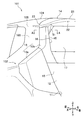
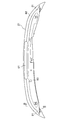
- FIG. 1 is a rear view of a vehicle according to a first embodiment of the present invention.
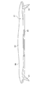
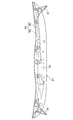
- FIG. 2 is an enlarged perspective view of the rear portion of the vehicle according to the first embodiment of the present invention.
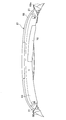
- FIG. 3 is an enlarged perspective view in which a part of the rear portion of the vehicle is cut along line AA in FIG.
- FIG. 4 is an enlarged perspective view of the deflector according to the first embodiment of the present invention and its surroundings as seen from below.
- FIG. 5 is a cross-sectional view taken along line BB in FIG.
- FIG. 6 is a view of the deflector according to the first embodiment of the present invention as viewed from the front side of the vehicle.
- FIG. 7 is a perspective view of the spoiler and the deflector according to the first embodiment of the present invention as seen from the vehicle rear side.
- FIG. 8 is a view of the outer member according to the first embodiment of the present invention as viewed from the vehicle lower side.
- FIG. 9 is a view of the spoiler body in which the inner member is attached to the outer member according to the first embodiment of the present invention, as viewed from the lower side of the vehicle.
- FIG. 10 is a view of the spoiler body of FIG. 9 as viewed from the lower side of the vehicle in a state where the center portion of the opening in the vehicle width direction is covered with a cover member and a deflector.
- FIG. 11 is a view of the spoiler body of FIG.
- FIG. 12 is an enlarged perspective view of a deflector mounting portion of the spoiler according to the first exemplary embodiment of the present invention.
- 13 is a cross-sectional view taken along the line CC of FIG.
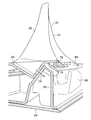
- FIG. 14 is the perspective view seen from the vehicle lower side of the spoiler and the deflector concerning Embodiment 2 of this invention.
- FIG. 15 is the perspective view seen from the vehicle front part side of the spoiler and the deflector concerning Embodiment 2 of this invention.
- FIG. 16 is an enlarged longitudinal sectional view taken along the line DD of FIG.
- FIG. 1 is a rear view of a vehicle 101 according to the first embodiment of the present invention.
- FIG. 2 is an enlarged perspective view of the rear portion 102 of the vehicle 101 according to the first embodiment of the present invention. 1 and the following drawings appropriately illustrate the direction of the vehicle 101 (the direction seen from the driver of the vehicle 101).
- a rear opening 11 that communicates with the interior of the vehicle is formed.
- the rear opening 11 can be opened and closed by a tailgate 12 serving as an opening / closing door.
- Rear combination lights 13 serving as functional parts are provided on both sides in the vehicle width direction of the rear portion 102 of the vehicle 101 when the tailgate 12 is closed.
- the rear combination light 13 has a part (rear combination light) 13a provided at the lower part of the rear pillar 103, and another part (rear combination light) 13b at, for example, both sides of the tailgate 12 in the vehicle width direction at the upper part of the rear combination light 13a. Each is provided.
- a spoiler (tail gate spoiler) 21 is provided at the upper end 14 of the tailgate 12.
- the spoiler 21 rectifies the traveling wind descending from the roof 104 of the vehicle 101 so as not to be caught in the rear portion of the vehicle 101.
- a deflector 31 is provided below the spoiler 21. The deflector 31 rectifies so as to flow from the side surface 105 of the vehicle 101 and prevent the traveling wind from being caught in the rear of the vehicle.
- the deflector 31 extends downward from the lower surface 22 of the spoiler 21 along the outer surface 15 of the tailgate 12. Further, the deflector 31 is disposed at a position close to the vehicle width direction central portion side by a predetermined distance from the vehicle width direction end portion 23 of the spoiler 21. More specifically, the deflector 31 is disposed at a position closer to the center in the vehicle width direction than the end 45 of the rear combination light 13b on the window panel 17 side (see also FIG. 3).
- the tailgate 12 includes a window opening 16 and a window panel 17 provided so as to cover the window opening 16.
- the rear combination light 13b is provided outside the window panel 17 in the vehicle width direction.
- the longitudinal direction of the rear combination light 13b extends along the side edge 18 (see FIG. 1) of the window panel 17, and the deflector 31 is closer to the center in the vehicle width direction than the side edge 18 of the window panel 17. It is arranged at the position.
- the deflector 31 is disposed at a position close to the vehicle width direction central portion side by a predetermined distance from the vehicle width direction end portion 23 of the spoiler 21. Therefore, even if the rear combination light 13b is provided along the side edge of the tailgate 12 in the vehicle width direction, the rear combination light 13b and the deflector 31 can be prevented from interfering with each other. Therefore, since the rear combination light 13b and the deflector 31 do not overlap with each other, even if the deflector 31 is provided, the third party can visually recognize the light emitted from the rear combination light 13b, and the function can be prevented from being hindered.
- FIG. 3 is an enlarged perspective view in which a part of the rear portion 102 of the vehicle 101 is cut along line AA in FIG.
- a wind guide surface 41 is formed on the outer surface of the rear combination light 13 b so as to project toward the vehicle rear side from the outer side in the vehicle width direction toward the center side.
- the deflector 31 is formed with a guide surface 42 that protrudes toward the vehicle rear side from the outer side in the vehicle width direction toward the center side.
- the air guide surface 41 and the guide surface 42 are aligned in the vehicle width direction (see FIGS. 2 and 3). Further, the air guide surface 41 and the guide surface 42 arranged in the vehicle width direction are formed on the same side in the vehicle width direction of the rear combination light 13b and the deflector 31, respectively (see FIG. 3).
- a light unit 43 for irradiating light is provided in the rear combination light 13b.
- the light unit 43 is provided in a flat portion 44 that is a portion closer to the center side in the vehicle width direction than the air guide surface 41 when viewed from the rear of the vehicle.
- the surface of the flat portion 44 is substantially parallel to the vehicle width direction.
- the light unit 43 is provided at the position of the flat portion 44 instead of the air guide surface 41 when viewed from the rear of the vehicle. This is because the rear combination light 13b appears to shine beautifully.
- the deflector 31 is disposed at a position overlapping the window panel 17 when viewed from the rear of the vehicle. In this way, if the deflector 31 is arranged at a position overlapping the window panel 17 when viewed from the rear of the vehicle, the vehicle 101 and the deflector 31 having the specifications provided with the deflector 31 are provided using the window panel 17 having the same specifications. It becomes possible to manufacture each of the vehicles 101 having no specifications.
- FIG. 4 is an enlarged perspective view of the deflector 31 and its surroundings as viewed from below.
- FIG. 5 is a cross-sectional view taken along line BB in FIG.
- FIG. 6 is a view of the deflector 31 as seen from the front side of the vehicle.
- an elastic member 51 is interposed between the deflector 31 and the window panel 17.
- sponge rubber may be attached to the vehicle front side of the deflector 31 so that it hits the outer surface of the window panel 17.
- the elastic member 51 may be composed of a double-sided tape, and the vehicle front side of the deflector 31 may be attached to the outer surface of the window panel 17 with the double-sided tape.
- the hook surface and loop surface of the hook-and-loop fastener may be attached to the vehicle front side of the deflector 31 and the outer surface of the window panel 17, respectively, so that the deflector 31 is detachably supported by the window panel 17. If the elastic member 51 is interposed between the deflector 31 and the window panel 17 in this way, vibration of the deflector 31 on the window panel 17 or generation of a collision sound between the window panel 17 and the deflector 31 is generated. Can be prevented.
- FIG. 7 is a perspective view of the spoiler 21 and the deflector 31 as seen from the vehicle rear side. As shown in FIG. 7, the deflector 31 is attached to the spoiler 21 (details will be described later). And the high mount stop lamp 61 is formed in the edge part of the vehicle rear part side in the longitudinal direction center part of the spoiler 21. As shown in FIG.
- FIG. 8 to 11 are explanatory views for explaining the structure of the spoiler 21.
- the spoiler 21 is roughly composed of a spoiler body 62 and a cover member 63.
- the spoiler body 62 is roughly composed of an outer member 64 and an inner member 65.
- FIG. 8 is a view of the outer member 64 as viewed from the lower side of the vehicle.
- FIG. 9 is a view of the spoiler body 62 in which the inner member 65 is attached to the outer member 64 as viewed from the lower side of the vehicle.
- the upper surface 66 constitutes at least a part of the upper surface 67 of the spoiler 21, in this example, the entire upper surface 67 (see FIG. 7).
- both end sides 68a of the lower surface 68 in the vehicle width direction constitute a part of the lower surface 22 (see FIGS. 1 and 2) of the spoiler 21.
- the inner member 65 is a component part of the spoiler 21 in which a boss for attaching the boss to the vehicle 101, a boss for attaching the high mount stop lamp 61, and the like are integrated.
- a large opening 69 is formed in the center of the spoiler body 62 in the vehicle width direction on the vehicle lower side of the spoiler body 62 in which the inner member 65 is attached to the outer member 64, and the inner member 65 is exposed from the opening 69.
- the cover member 63 is attached to the spoiler body 62 so as to cover a part of the opening 69, in this example, most of the central portion in the vehicle width direction.
- the deflector 31 is attached to the spoiler body 62 so as to cover the remaining part of the opening 69, in this example, both ends in the vehicle width direction.
- FIG. 10 is a view of the spoiler 21 viewed from the lower side of the vehicle with the spoiler body 62 of FIG. 9 covered with the cover member 63 and the deflector 31 at the center of the opening 69 in the vehicle width direction.
- FIG. 11 is a view of the spoiler 21 as viewed from the lower side of the vehicle with the spoiler main body 62 of FIG. In the example of FIG.
- the deflector 31 since the deflector 31 is not provided, both ends (openings) 69a of the opening 69 in the vehicle width direction are exposed. 10 and 11, the recess 70 formed in the cover member 63 is a rear wiper storage position (not shown).
- the cover member 63 for covering the opening 69 of the spoiler body 62 can be downsized.
- the entire opening 69 of the spoiler body 62 is covered with the cover member 63 and the pair of deflectors 31.
- FIG. 12 is an enlarged perspective view of a portion where the deflector 31 is attached to the spoiler 21, and FIG. 13 is a cross-sectional view taken along the line CC of FIG.
- the deflector 31 includes fixed portions 71 and 72.
- the fixed portion 71 projects from the proximal end portion of the guide surface forming plate 91 on which the guide surface 42 is formed toward the vehicle width direction center portion side.
- the guide surface forming plate 91 is provided with a support plate 92 so as to form an acute angle with the guide surface forming plate 91
- the fixing portion 72 projects from the base end portion of the support plate 92 toward the center in the vehicle width direction. ing.
- the fixing portions 71 and 72 are fastened and fixed to the spoiler body 62 (the outer member 64 thereof) with a bolt (not shown).
- the deflector 31 is attached to the spoiler body 62 (the outer member 64 thereof) at the fixing portions 71 and 72. Then, the spoiler body 62 with the deflector 31 attached and the cover member 63 not attached is attached to the vehicle 101. Next, the cover member 63 is attached to the spoiler body 62 in a state where the cover member 63 attached to the vehicle 101 is not attached.
- the cover member 63 is fastened to the spoiler body 62 (the inner member 65 thereof) with a bolt (not shown) as indicated by an arrow 73.
- the cover member 63 is fixed to the spoiler body 62 with the contact portion 75 of the cover member 63 being in contact with the contact portion 76 of the deflector 31. That is, in the part of the deflector 31 that is separated from the edge 69 (69a) of the opening and cannot be attached to the spoiler body 62 by the fixing parts 71 and 72, the contact part 76 is a part 75 of the cover member 63. It can be pressed down. Moreover, the contact part 76 is provided in the comparative vicinity of the fixing parts 71 and 72 (see FIG. 12).
- the deflector 31 can be firmly attached to the spoiler body 62 (the outer member 64 thereof) at the fixing portions 71 and 72 at a portion along the edge of the opening 69 (69a). Even when the cover member 63 is removed, the deflector 31 can be held by the spoiler body 62 by the fixing portions 71 and 72. Therefore, the cover member 63 can be attached to the spoiler body 62 after the spoiler body 62 with the cover member 63 not attached is attached to the vehicle 101.
- the deflector 31 is mutated to the outside of the vehicle by the contact portion 76. Can be prevented.
- the cover member 63 is only applied to the deflector 31 at the contact portion 76 and does not require bolt fastening or the like, so that the assembling property of the cover member 63 can be improved. Further, since the abutting portion 76 is provided relatively near the fixed portion 72, the deflector 31 can be supported by the cover member 63 more firmly.
- FIG. 14 is a perspective view of the spoiler 21 and the deflector 31 according to the present embodiment as viewed from the vehicle rear side
- FIG. 15 is a perspective view of the spoiler 21 and the deflector 31 according to the present embodiment as viewed from the vehicle front side.
- members and the like that are the same as those in the first embodiment are denoted by the same reference numerals as those in the first embodiment, and detailed descriptions thereof are omitted.
- the spoiler 21 and the deflector 31 of the present embodiment are different from those of the first embodiment in that the deflector 31 is formed integrally with the cover member 63.
- FIG. 16 is an enlarged longitudinal sectional view taken along the line DD in FIG.
- the spoiler body 62 (outer member 64) hits the outer surface of the window panel 17 of the tailgate 12 (FIGS. 1 and 2) in the vicinity of the deflector 31.
- the support part 81 which touches in the state is further provided, and the deflector 31 covers the support part 81.
- the lower portion of the outer member 64 includes a portion 82 that extends obliquely downward so as to approach the vehicle rear portion 102, a portion 83 that extends substantially vertically from the tip of this portion 82 toward the window panel 17, and this portion 83, a portion (support portion) 81 extending from the front end portion of the vehicle panel 102 to the oblique lower portion of the vehicle rear portion 102 substantially parallel to the outer surface of the window panel 17 is provided.
- the rib 85 as a reinforcement member is interposed in the recessed part 84 by the side of the deflector 31 formed by the part 82 of the outer member 64, the part 83, and the support part 81.
- An elastic member 51 is interposed between the support portion 81 and the window panel 17.
- the spoiler body 62 (outer member 64 thereof) can be firmly supported on the outer surface of the window panel 17 of the tailgate 12 by the support portion 81 in the vicinity of the deflector 31, the spoiler body 62 and the deflector 31 Support rigidity can be increased. Moreover, this support rigidity can be further improved by interposing the rib 85 as described above. Further, it is possible to prevent the spoiler body 62 (the outer member 64) and the deflector 31 from colliding with each other due to bending of the spoiler body 62 (the outer member 64). Moreover, the support portion 81 can be shielded by the deflector 31 so that it cannot be seen from the outside.
Abstract
Description
そこで、本発明は、機能部品とデフレクタの両方を互いに干渉し合うことなく車両後部に設けることができる車両後部構造を提供することを課題とする。 However, when a functional component such as a rear combination lamp is provided along the side edge of the tailgate in the vehicle width direction, if the deflector is provided at both ends of the spoiler, the functional component and the deflector interfere with each other. End up. Therefore, the technique of Patent Document 1 has a problem that both the functional component and the deflector cannot be provided at the rear of the vehicle without interfering with each other.
Then, this invention makes it a subject to provide the vehicle rear part structure which can be provided in a vehicle rear part, without interfering mutually with both a functional component and a deflector.
本発明によれば、デフレクタはスポイラの車幅方向端部から予め定められた距離だけ車幅方向中央部側に寄った位置に配置されている。よって、開閉ドアの車幅方向の側縁部に沿ってリアコンビネーションランプ等の機能部品を設けても、機能部品とデフレクタとが互いに干渉し合うことを防止することができる。 In order to solve the above problems, an embodiment of the present invention includes a rear opening provided at a rear portion of a vehicle, an opening / closing door that opens / closes the rear opening, a spoiler provided at an upper end portion of the opening / closing door, A deflector provided below, the deflector extending downward from the lower surface of the spoiler along the outer surface of the open / close door, and a center in the vehicle width direction by a predetermined distance from an end in the vehicle width direction of the spoiler It is the vehicle rear part structure arrange | positioned in the position which approached the part side.
According to the present invention, the deflector is disposed at a position close to the center in the vehicle width direction by a predetermined distance from the end in the vehicle width direction of the spoiler. Therefore, even if a functional component such as a rear combination lamp is provided along the side edge of the opening / closing door in the vehicle width direction, the functional component and the deflector can be prevented from interfering with each other.
本発明では、機能部品とデフレクタとが重ならないので、デフレクタを設けても機能部品の機能を妨げることを防止することができる。 In this case, the opening / closing door includes a window opening, a window panel provided so as to cover the window opening, and a functional component provided on the outer side in the vehicle width direction from the window panel, the functional component being The longitudinal direction extends along the side edge of the window panel, and the deflector is disposed at a position closer to the center in the vehicle width direction than the window panel side end of the functional component. It may be.
In the present invention, since the functional component and the deflector do not overlap with each other, it is possible to prevent the function of the functional component from being hindered even if the deflector is provided.
本発明では、導風面により車両後方に導かれた走行風が当該導風面から剥離した後に開閉ドアの外面側に巻き返すことを案内面で防止することができる。 In this case, the functional component further includes a wind guide surface that protrudes toward the vehicle rear side from the outside in the vehicle width direction toward the center portion side, and the deflector extends from the outside in the vehicle width direction toward the center portion side. A guide surface projecting to the vehicle rear side, the guide surface being aligned with the air guide surface in the vehicle width direction, and the air guide surface and the deflector on the same side in the vehicle width direction of the functional component and the deflector, respectively. The guide surface may be formed.
In the present invention, it is possible to prevent the traveling wind guided to the rear of the vehicle by the air guide surface from being turned back to the outer surface side of the open / close door after being separated from the air guide surface.
本発明では、デフレクタを車両後方から見てウインドウパネルと重なる位置に配置するので、同じ仕様のウインドウパネルを用いて、デフレクタを設けた仕様の車両とデフレクタを設けない仕様の車両とをそれぞれ製造することができる。 In the above case, the open / close door includes a window opening and a window panel provided to cover the window opening, and the deflector is disposed at a position overlapping the window panel when viewed from the rear of the vehicle. You may make it.
In the present invention, since the deflector is disposed at a position overlapping the window panel when viewed from the rear of the vehicle, a vehicle having a specification with a deflector and a vehicle having a specification without a deflector are manufactured using the window panel having the same specification. be able to.
本発明では、弾性部材により、ウインドウパネル上でのデフレクタの振動や、あるいは、ウインドウパネルとデフレクタとの衝突音の発生を防止することができる。 In this case, you may make it further provide the elastic member interposed between the said deflector and the said window panel.
In the present invention, the elastic member can prevent the vibration of the deflector on the window panel or the collision sound between the window panel and the deflector.
本発明では、デフレクタでもスポイラ本体の開口を覆うので、スポイラ本体の開口を覆うためのカバー部材を小型化することができる。 In the above-described case, the spoiler has a surface that constitutes at least a part of the upper surface of the spoiler and a part of the lower surface, and a spoiler body in which an opening is formed on the lower surface side, and a cover member that covers a part of the opening. And the deflector may cover the remaining part of the opening.
In the present invention, since the deflector covers the opening of the spoiler body, the cover member for covering the opening of the spoiler body can be downsized.
本発明では、開口の縁部に沿う部位ではスポイラ本体にデフレクタを固定部により強固に取り付けることができる。
また、カバー部材を外した状態でも、固定部によりデフレクタをスポイラ本体に保持させることができる。
さらに、デフレクタのうち、開口の縁部と離間していて、固定部によりスポイラ本体に取り付けられない部位では、当接部によりデフレクタが車外側に変異するのを防止することができる。
その上、カバー部材は当接部ではデフレクタに当てられているだけであるため、カバー部材の組み付け性を向上させることができる。 In this case, the deflector includes a fixed portion that is fixed to the spoiler body at a portion along the edge of the opening, and the cover member that is separated from the edge of the opening and adjacent to the cover member. And an abutting portion applied from the outside.
In the present invention, the deflector can be firmly attached to the spoiler body by the fixing portion at the portion along the edge of the opening.
Further, even when the cover member is removed, the deflector can be held on the spoiler body by the fixing portion.
Furthermore, in a part of the deflector that is separated from the edge of the opening and cannot be attached to the spoiler body by the fixing part, the deflector can be prevented from being deformed to the outside of the vehicle by the contact part.
In addition, since the cover member is only applied to the deflector at the contact portion, the assembling property of the cover member can be improved.
本発明では、さらに強固にカバー部材でデフレクタを支持することができる。 In this case, the contact portion may be provided in the vicinity of the fixed portion.
In the present invention, the deflector can be more firmly supported by the cover member.
本発明では、デフレクタとカバー部材とを一体に形成するので、部品点数を削減することができ、デフレクタ取り付けのための工数を削減することができる。
また、デフレクタをカバー部材と別部品で構成する場合に比べ、カバー部材をスポイラ本体に取り付ける部分でも間接的にデフレクタを支持することができるので、デフレクタを強固に固定することができる。 In the above-described case, the spoiler has a surface that constitutes at least a part of the upper surface of the spoiler and a part of the lower surface, and a spoiler body in which an opening is formed on the lower surface side, and a cover member that covers a part of the opening. The deflector may be formed integrally with the cover member.
In the present invention, since the deflector and the cover member are integrally formed, the number of parts can be reduced, and the number of steps for attaching the deflector can be reduced.
Further, as compared with the case where the deflector is configured as a separate part from the cover member, the deflector can be indirectly supported even at the portion where the cover member is attached to the spoiler body, so that the deflector can be firmly fixed.
本発明では、デフレクタの近傍でスポイラ本体を開閉ドアの外面に支持部によって強固に支持させることができるので、デフレクタの支持剛性を高めることができる。
また、スポイラ本体の撓み等によりスポイラ本体とデフレクタとが衝突することを防止することができる。 In this case, the spoiler body may further include a support portion that is in contact with the outer surface of the open / close door in the vicinity of the deflector.
In the present invention, the spoiler body can be firmly supported by the support portion on the outer surface of the opening / closing door in the vicinity of the deflector, so that the support rigidity of the deflector can be increased.
Further, it is possible to prevent the spoiler body and the deflector from colliding with each other due to bending of the spoiler body.
[実施形態1]
まず、本発明の実施形態1である車両後部構造について説明する。図1は、本発明の実施形態1にかかる車両101の背面図である。図2は、本発明の実施形態1にかかる車両101の後部102の拡大斜視図である。なお、図1以下の図面には車両101の方向(車両101の運転者からみた方向)を適宜図示している。 Hereinafter, a plurality of embodiments of the present invention will be described with reference to the drawings.
[Embodiment 1]
First, the vehicle rear part structure which is Embodiment 1 of this invention is demonstrated. FIG. 1 is a rear view of a
なお、リアコンビライト13b内には、光を照射するためのライトユニット43が設けられている。このライトユニット43は、車両後方から見て導風面41より車幅方向の中央部側寄りの部分である平坦部44に設けられている。平坦部44は表面が車幅方向にほぼ平行である。 In such a configuration of the
A
このように、デフレクタ31を車両後方から見てウインドウパネル17と重なる位置に配置するようにすれば、同じ仕様のウインドウパネル17を用いて、デフレクタ31を設けた仕様の車両101とデフレクタ31を設けない仕様の車両101とをそれぞれ製造することが可能となる。 As shown in FIG. 3, the
In this way, if the
図4~図6に示すように、デフレクタ31とウインドウパネル17との間には弾性部材51が介装されている。弾性部材51としては、スポンジゴムをデフレクタ31の車両前方側に取り付けて、これがウインドウパネル17の外面に当たるようにしてもよい。あるいは、弾性部材51を両面テープで構成し、当該両面テープでデフレクタ31の車両前方側をウインドウパネル17の外面に貼り付けてもよい。あるいは、面ファスナのフック面とループ面とをそれぞれデフレクタ31の車両前方側とウインドウパネル17の外面とに取り付け、デフレクタ31がウインドウパネル17に着脱自在に支持されるようにしてもよい。
このように、デフレクタ31とウインドウパネル17との間に弾性部材51を介装すれば、ウインドウパネル17上でのデフレクタ31の振動や、あるいは、ウインドウパネル17とデフレクタ31との衝突音の発生を防止することができる。 FIG. 4 is an enlarged perspective view of the
As shown in FIGS. 4 to 6, an
If the
このように、スポイラ21においては、デフレクタ31によってもスポイラ本体62の開口69aを覆うので、スポイラ本体62の開口69を覆うためのカバー部材63を小型化することができる。このように、本実施形態では、スポイラ本体62の開口69の全体をカバー部材63及び一対のデフレクタ31により覆うようにしている。 The
Thus, in the
また、カバー部材63を外した状態でも、固定部71,72によりデフレクタ31をスポイラ本体62に保持させることができる。よって、カバー部材63を未装着の状態のスポイラ本体62を車両101に取り付けた後に、カバー部材63をスポイラ本体62に取り付けることが可能となる。 With such an attachment structure, the
Even when the
その上、カバー部材63は当接部76ではデフレクタ31に当てられているだけであり、ボルト締結等を不要としているため、カバー部材63の組み付け性を向上させることができる。
また、当接部76は、固定部72の比較的近傍に設けられているので、さらに強固にカバー部材63でデフレクタ31を支持することができる。 Further, in the
In addition, the
Further, since the abutting
次に、本発明の実施形態2である車両後部構造について説明する。図14は、本実施形態のスポイラ21及びデフレクタ31の車両後部側から見た斜視図、図15は、本実施形態のスポイラ21及びデフレクタ31の車両前部側から見た斜視図である。以下の説明では、実施形態1と共通する部材等については、前述の実施形態1と同一の符号を付し、詳細な説明は省略する。
本実施形態のスポイラ21及びデフレクタ31が実施形態1と相違する点は、まず、デフレクタ31がカバー部材63と一体に形成されていることである。 [Embodiment 2]
Next, a vehicle rear portion structure that is Embodiment 2 of the present invention will be described. FIG. 14 is a perspective view of the
The
また、実施形態1のようにデフレクタ31をカバー部材63と別部品で構成する場合に比べ、カバー部材63をスポイラ本体62に取り付ける部分でも間接的にデフレクタ31を支持することができるので、デフレクタ31を強固に固定することができる。
また、図16は、図14のD-D線で切断した拡大縦断面図である。本実施形態が実施形態1と相違するもう一つの点は、スポイラ本体62(アウタ部材64)が、デフレクタ31の近傍でテールゲート12(図1、図2)のウインドウパネル17の外面に当たった状態で接している支持部81をさらに備え、デフレクタ31は支持部81を覆っていることである。 In this embodiment, since the
In addition, as compared with the case where the
FIG. 16 is an enlarged longitudinal sectional view taken along the line DD in FIG. Another difference between the present embodiment and the first embodiment is that the spoiler body 62 (outer member 64) hits the outer surface of the
また、スポイラ本体62(のアウタ部材64)の撓み等によりスポイラ本体62(のアウタ部材64)とデフレクタ31とが衝突することを防止することができる。
しかも、支持部81をデフレクタ31で遮蔽して外部からは見えないようにすることができる。 In the present embodiment, since the spoiler body 62 (
Further, it is possible to prevent the spoiler body 62 (the outer member 64) and the
Moreover, the
なお、本発明は上記した各実施形態に限定されるものではなく、様々な変形例が含まれることは言うまでもない。上述した各実施形態は何れも本発明の一実施形態にとどまる。 Except for the above configuration, the configuration of the present embodiment is the same as that of the first embodiment, and a detailed description thereof will be omitted.
Note that the present invention is not limited to each of the above-described embodiments, and it goes without saying that various modifications are included. Each of the above-described embodiments is only one embodiment of the present invention.
12 テールゲート(開閉ドア)
13b リアコンビライト(機能部品)
14 テールゲートの上端部
15 テールゲートの外面
16 ウインドウ開口
17 ウインドウパネル
18 ウインドウパネルの側縁部
21 スポイラ
22 スポイラの下面
23 スポイラの車幅方向端部
31 デフレクタ
41 導風面
42 案内面
51 弾性部材
62 スポイラ本体
63 カバー部材
69 開口
69a 開口の残りの一部
71,72 固定部
76 当接部
81 支持部 11
13b Rear combination light (functional parts)
DESCRIPTION OF
Claims (10)
- 車両の後部に設けられた後部開口と、
前記後部開口を開閉する開閉ドアと、
前記開閉ドアの上端部に設けられるスポイラと、
前記スポイラの下方に設けられるデフレクタと、
を備え、
前記デフレクタは、前記スポイラの下面から前記開閉ドアの外面に沿って下方に延び、前記スポイラの車幅方向端部から予め定められた距離だけ車幅方向中央部側に寄った位置に配置されている、
車両後部構造。 A rear opening provided at the rear of the vehicle;
An opening and closing door for opening and closing the rear opening;
A spoiler provided at the upper end of the door;
A deflector provided below the spoiler;
With
The deflector extends downward from the lower surface of the spoiler along the outer surface of the open / close door, and is disposed at a position close to the vehicle width direction central portion side by a predetermined distance from the vehicle width direction end of the spoiler. Yes,
Vehicle rear structure. - 前記開閉ドアは、
ウインドウ開口と、
前記ウインドウ開口を覆うように設けられたウインドウパネルと、
前記ウインドウパネルより車幅方向外側に設けられた機能部品と、
を備え、
前記機能部品は、その長手方向が前記ウインドウパネルの側縁部に沿って延びていて、
前記デフレクタは、前記機能部品の前記ウインドウパネル側端部より車幅方向中央部側に寄った位置に配置されている、
請求項1に記載の車両後部構造。 The open / close door is
Window opening,
A window panel provided to cover the window opening;
Functional parts provided outside the window panel in the vehicle width direction,
With
The functional component has a longitudinal direction extending along a side edge of the window panel,
The deflector is disposed at a position closer to the vehicle width direction center than the window panel side end of the functional component.
The vehicle rear structure according to claim 1. - 前記機能部品は、車幅方向の外側から中央部側に向かうにつれて車両後方側に張り出す導風面をさらに備え、
前記デフレクタは、車幅方向の外側から中央部側に向かうにつれて車両後方側に張り出す案内面をさらに備え、
前記案内面は、前記導風面と車幅方向に並んでいて、前記機能部品及び前記デフレクタのそれぞれ車幅方向の同じ側に前記導風面及び前記案内面が形成されている、
請求項2に記載の車両後部構造。 The functional component further includes a wind guide surface that protrudes toward the vehicle rear side from the outside in the vehicle width direction toward the center side.
The deflector further includes a guide surface that protrudes toward the vehicle rear side from the outside in the vehicle width direction toward the center side.
The guide surface is aligned with the air guide surface in the vehicle width direction, and the air guide surface and the guide surface are formed on the same side in the vehicle width direction of the functional component and the deflector, respectively.
The vehicle rear structure according to claim 2. - 前記開閉ドアは、
ウインドウ開口と、
前記ウインドウ開口を覆うように設けられたウインドウパネルと、
を備え、
前記デフレクタは、車両後方から見て前記ウインドウパネルと重なる位置に配置されている、
請求項1に記載の車両後部構造。 The open / close door is
Window opening,
A window panel provided to cover the window opening;
With
The deflector is disposed at a position overlapping the window panel as seen from the rear of the vehicle.
The vehicle rear structure according to claim 1. - 前記デフレクタと前記ウインドウパネルとの間に介装された弾性部材をさらに備えている、ことを特徴とする請求項4に記載の車両後部構造。 The vehicle rear structure according to claim 4, further comprising an elastic member interposed between the deflector and the window panel.
- 前記スポイラは、
表面が前記スポイラの上面の少なくとも一部及び下面の一部を構成し、前記下面側に開口が形成されたスポイラ本体と、
前記開口の一部を覆うカバー部材と、
をさらに備え、
前記デフレクタは、前記開口の残りの一部を覆っている、
請求項1~5の何れかの一項に記載の車両後部構造。 The spoiler is
A spoiler body whose surface constitutes at least a part of the upper surface of the spoiler and a part of the lower surface, and an opening is formed on the lower surface side;
A cover member covering a part of the opening;
Further comprising
The deflector covers the remaining part of the opening;
The vehicle rear structure according to any one of claims 1 to 5. - 前記デフレクタは、
前記開口の縁部に沿う部位で前記スポイラ本体に固定される固定部と、
前記開口の縁部と離間し且つ前記カバー部材と隣接する部位で前記カバー部材が車外側から当てられている当接部と、
をさらに備えている請求項6に記載の車両後部構造。 The deflector is
A fixed portion fixed to the spoiler body at a portion along the edge of the opening;
An abutting portion where the cover member is applied from the outside of the vehicle at a portion separated from the edge of the opening and adjacent to the cover member;
The vehicle rear portion structure according to claim 6, further comprising: - 前記当接部は、前記固定部の近傍に設けられている、請求項7に記載の車両後部構造。 The vehicle rear portion structure according to claim 7, wherein the contact portion is provided in the vicinity of the fixed portion.
- 前記スポイラは、
表面が前記スポイラの上面の少なくとも一部及び下面の一部を構成し、前記下面側に開口が形成されたスポイラ本体と、
前記開口の一部を覆うカバー部材と、
をさらに備え、
前記デフレクタは、前記カバー部材と一体に形成されている、
請求項1~5の何れかの一項に記載の車両後部構造。 The spoiler is
A spoiler body whose surface constitutes at least a part of the upper surface of the spoiler and a part of the lower surface, and an opening is formed on the lower surface side;
A cover member covering a part of the opening;
Further comprising
The deflector is formed integrally with the cover member.
The vehicle rear structure according to any one of claims 1 to 5. - 前記スポイラ本体は、前記デフレクタの近傍で前記開閉ドアの外面に当たった状態で接している支持部をさらに備えている、請求項9に記載の車両後部構造。 The vehicle rear structure according to claim 9, wherein the spoiler body further includes a support portion that is in contact with the outer surface of the open / close door in the vicinity of the deflector.
Priority Applications (4)
| Application Number | Priority Date | Filing Date | Title |
|---|---|---|---|
| EP14770906.7A EP2977299B1 (en) | 2013-03-21 | 2014-03-19 | Structure for rear part of vehicle |
| JP2015506815A JP5848852B2 (en) | 2013-03-21 | 2014-03-19 | Vehicle rear structure |
| US14/778,345 US9566847B2 (en) | 2013-03-21 | 2014-03-19 | Structure for rear part of vehicle |
| CN201480017136.1A CN105073565B (en) | 2013-03-21 | 2014-03-19 | Structure for rear part of vehicle |
Applications Claiming Priority (2)
| Application Number | Priority Date | Filing Date | Title |
|---|---|---|---|
| JP2013-057830 | 2013-03-21 | ||
| JP2013057830 | 2013-03-21 |
Publications (1)
| Publication Number | Publication Date |
|---|---|
| WO2014148526A1 true WO2014148526A1 (en) | 2014-09-25 |
Family
ID=51580201
Family Applications (1)
| Application Number | Title | Priority Date | Filing Date |
|---|---|---|---|
| PCT/JP2014/057462 WO2014148526A1 (en) | 2013-03-21 | 2014-03-19 | Structure for rear part of vehicle |
Country Status (5)
| Country | Link |
|---|---|
| US (1) | US9566847B2 (en) |
| EP (1) | EP2977299B1 (en) |
| JP (1) | JP5848852B2 (en) |
| CN (1) | CN105073565B (en) |
| WO (1) | WO2014148526A1 (en) |
Cited By (2)
| Publication number | Priority date | Publication date | Assignee | Title |
|---|---|---|---|---|
| CN106143078A (en) * | 2015-05-14 | 2016-11-23 | 本田技研工业株式会社 | Vehicle Structure |
| WO2020196187A1 (en) * | 2019-03-27 | 2020-10-01 | いすゞ自動車株式会社 | Vehicle aerodynamic member, and vehicle |
Families Citing this family (4)
| Publication number | Priority date | Publication date | Assignee | Title |
|---|---|---|---|---|
| KR101756031B1 (en) * | 2016-07-08 | 2017-07-10 | 현대자동차주식회사 | Rear bump variable spoiler system for vehicle |
| US10744859B2 (en) * | 2018-05-17 | 2020-08-18 | GM Global Technology Operations LLC | Method for mitigating backglass contamination |
| WO2019246103A1 (en) * | 2018-06-18 | 2019-12-26 | Magna Exteriors Inc. | Active aerodynamics liftgate spoiler design with multi 4 bar kinematic linkages |
| DE102019116206A1 (en) | 2019-06-14 | 2020-12-17 | Volkswagen Aktiengesellschaft | Tailgate with mechanically secured rear and side spoiler connection |
Citations (5)
| Publication number | Priority date | Publication date | Assignee | Title |
|---|---|---|---|---|
| JPS58100875U (en) * | 1981-12-28 | 1983-07-08 | 日産自動車株式会社 | Device for preventing the generation of stuck vortices at the rear of the car body |
| JPS62111283U (en) * | 1985-12-30 | 1987-07-15 | ||
| JPH06122384A (en) * | 1991-09-26 | 1994-05-06 | Nissan Motor Co Ltd | Installation structure of exterior equipment for car body |
| DE102007032322A1 (en) * | 2007-07-11 | 2009-01-15 | Dr. Ing. H.C. F. Porsche Aktiengesellschaft | Air conducting device for arrangement in motor vehicle e.g. racing car, has conducting elements provided in lateral ends of body, and conducting surface turned towards flow chamber for retaining turbulence cross-flow |
| WO2011018566A1 (en) | 2009-08-11 | 2011-02-17 | Peugeot Citroën Automobiles SA | Rear spoiler for a motor vehicle, and vehicle provided with such a rear spoiler |
Family Cites Families (14)
| Publication number | Priority date | Publication date | Assignee | Title |
|---|---|---|---|---|
| DE2535882C3 (en) * | 1975-08-12 | 1980-05-29 | Daimler-Benz Ag, 7000 Stuttgart | Shield-like guiding device for the rear window of a notchback motor vehicle |
| US5287004A (en) * | 1992-09-04 | 1994-02-15 | Finley Michael D | Automobile air and ground effects power package |
| JP2884043B2 (en) | 1995-04-03 | 1999-04-19 | 田村プラスチック製品株式会社 | Car rear spoiler |
| DE102005008882B4 (en) * | 2005-02-26 | 2021-05-06 | Bayerische Motoren Werke Aktiengesellschaft | Roof spoiler |
| JP2007001521A (en) | 2005-06-27 | 2007-01-11 | Mazda Motor Corp | Vehicle rear body structure |
| US20060290169A1 (en) | 2005-06-27 | 2006-12-28 | Mazda Motor Corporation | Vehicle rear body structure |
| DE102007031607A1 (en) * | 2007-07-06 | 2009-01-08 | Dr. Ing. H.C. F. Porsche Aktiengesellschaft | fastening device |
| DE102008036283B4 (en) * | 2008-08-04 | 2017-06-29 | Dr. Ing. H.C. F. Porsche Aktiengesellschaft | Rear-side spoiler for a motor vehicle |
| CN202345797U (en) | 2011-11-29 | 2012-07-25 | 富士重工业株式会社 | Rear spoiler structure for vehicle |
| CN202806908U (en) | 2012-09-07 | 2013-03-20 | 富士重工业株式会社 | Rear spoiler of vehicle |
| FR3010381B1 (en) * | 2013-09-09 | 2017-05-05 | Plastic Omnium Cie | SPOILER FOR MOTOR VEHICLE TAIL |
| US9315223B2 (en) * | 2014-04-11 | 2016-04-19 | Honda Motor Co., Ltd. | Light weight integrated tailgate spoiler |
| DE102014017606A1 (en) * | 2014-11-27 | 2016-06-02 | GM Global Technology Operations LLC (n. d. Ges. d. Staates Delaware) | BUILDING PART, SPOILER EQUIPMENT AND MOTOR VEHICLE |
| US9487068B2 (en) * | 2014-12-19 | 2016-11-08 | Fca Us Llc | Liftgate inner die cast profile |
-
2014
- 2014-03-19 US US14/778,345 patent/US9566847B2/en active Active
- 2014-03-19 EP EP14770906.7A patent/EP2977299B1/en not_active Not-in-force
- 2014-03-19 JP JP2015506815A patent/JP5848852B2/en active Active
- 2014-03-19 WO PCT/JP2014/057462 patent/WO2014148526A1/en active Application Filing
- 2014-03-19 CN CN201480017136.1A patent/CN105073565B/en active Active
Patent Citations (5)
| Publication number | Priority date | Publication date | Assignee | Title |
|---|---|---|---|---|
| JPS58100875U (en) * | 1981-12-28 | 1983-07-08 | 日産自動車株式会社 | Device for preventing the generation of stuck vortices at the rear of the car body |
| JPS62111283U (en) * | 1985-12-30 | 1987-07-15 | ||
| JPH06122384A (en) * | 1991-09-26 | 1994-05-06 | Nissan Motor Co Ltd | Installation structure of exterior equipment for car body |
| DE102007032322A1 (en) * | 2007-07-11 | 2009-01-15 | Dr. Ing. H.C. F. Porsche Aktiengesellschaft | Air conducting device for arrangement in motor vehicle e.g. racing car, has conducting elements provided in lateral ends of body, and conducting surface turned towards flow chamber for retaining turbulence cross-flow |
| WO2011018566A1 (en) | 2009-08-11 | 2011-02-17 | Peugeot Citroën Automobiles SA | Rear spoiler for a motor vehicle, and vehicle provided with such a rear spoiler |
Non-Patent Citations (1)
| Title |
|---|
| See also references of EP2977299A4 |
Cited By (3)
| Publication number | Priority date | Publication date | Assignee | Title |
|---|---|---|---|---|
| CN106143078A (en) * | 2015-05-14 | 2016-11-23 | 本田技研工业株式会社 | Vehicle Structure |
| CN106143078B (en) * | 2015-05-14 | 2018-11-09 | 本田技研工业株式会社 | Vehicle structure |
| WO2020196187A1 (en) * | 2019-03-27 | 2020-10-01 | いすゞ自動車株式会社 | Vehicle aerodynamic member, and vehicle |
Also Published As
| Publication number | Publication date |
|---|---|
| CN105073565A (en) | 2015-11-18 |
| EP2977299A1 (en) | 2016-01-27 |
| US20160272052A1 (en) | 2016-09-22 |
| US9566847B2 (en) | 2017-02-14 |
| JPWO2014148526A1 (en) | 2017-02-16 |
| EP2977299A4 (en) | 2017-01-11 |
| EP2977299B1 (en) | 2018-03-07 |
| JP5848852B2 (en) | 2016-01-27 |
| CN105073565B (en) | 2017-05-03 |
Similar Documents
| Publication | Publication Date | Title |
|---|---|---|
| JP5848852B2 (en) | Vehicle rear structure | |
| JP6049390B2 (en) | Vehicle back door | |
| JP6008401B2 (en) | Deflector device for vehicle | |
| JP2016215680A (en) | Vehicle structure | |
| JP4489722B2 (en) | Vehicle side structure | |
| EP2923870B1 (en) | Reinforcing structure of vehicle door | |
| JP2011005988A (en) | Cowl top cover structure | |
| JP6649608B2 (en) | Mounting structure of tailgate door switch | |
| JP2008290605A (en) | Structure of rear bumper cover | |
| JPWO2014034218A1 (en) | Vehicle door | |
| JP2011152870A (en) | Cover member and mounting structure thereof | |
| JP5109522B2 (en) | Vehicle sunroof structure | |
| JP6084702B2 (en) | Vehicle door | |
| US20190162008A1 (en) | Vehicular door | |
| JP6068217B2 (en) | Vehicle front structure | |
| JP2022048562A (en) | Mounting structure of roof lining | |
| KR100736966B1 (en) | Anti-pinch strip sensor mounting structure | |
| JP4701922B2 (en) | Lining structure of wheel house | |
| JP5870595B2 (en) | Vehicle door structure | |
| JP2010235092A (en) | Door for automobile | |
| JP2019107985A (en) | Cowl top garnish | |
| JP2012111349A (en) | Vehicle | |
| JP2018075997A (en) | Structure of cowl garnish | |
| JP2017218072A (en) | Cowl top garnish fixing structure | |
| JP2009096292A (en) | Structure of vehicle back door |
Legal Events
| Date | Code | Title | Description |
|---|---|---|---|
| WWE | Wipo information: entry into national phase |
Ref document number: 201480017136.1 Country of ref document: CN |
|
| 121 | Ep: the epo has been informed by wipo that ep was designated in this application |
Ref document number: 14770906 Country of ref document: EP Kind code of ref document: A1 |
|
| ENP | Entry into the national phase |
Ref document number: 2015506815 Country of ref document: JP Kind code of ref document: A |
|
| WWE | Wipo information: entry into national phase |
Ref document number: 2014770906 Country of ref document: EP |
|
| WWE | Wipo information: entry into national phase |
Ref document number: 14778345 Country of ref document: US |
|
| NENP | Non-entry into the national phase |
Ref country code: DE |