WO2014147868A1 - Catheter for treatment of sinusitis - Google Patents
Catheter for treatment of sinusitis Download PDFInfo
- Publication number
- WO2014147868A1 WO2014147868A1 PCT/JP2013/074220 JP2013074220W WO2014147868A1 WO 2014147868 A1 WO2014147868 A1 WO 2014147868A1 JP 2013074220 W JP2013074220 W JP 2013074220W WO 2014147868 A1 WO2014147868 A1 WO 2014147868A1
- Authority
- WO
- WIPO (PCT)
- Prior art keywords
- balloon
- nostril
- catheter
- lumen
- posterior
- Prior art date
Links
Images


Classifications
-
- A—HUMAN NECESSITIES
- A61—MEDICAL OR VETERINARY SCIENCE; HYGIENE
- A61M—DEVICES FOR INTRODUCING MEDIA INTO, OR ONTO, THE BODY; DEVICES FOR TRANSDUCING BODY MEDIA OR FOR TAKING MEDIA FROM THE BODY; DEVICES FOR PRODUCING OR ENDING SLEEP OR STUPOR
- A61M25/00—Catheters; Hollow probes
- A61M25/10—Balloon catheters
- A61M25/1011—Multiple balloon catheters
-
- A—HUMAN NECESSITIES
- A61—MEDICAL OR VETERINARY SCIENCE; HYGIENE
- A61B—DIAGNOSIS; SURGERY; IDENTIFICATION
- A61B17/00—Surgical instruments, devices or methods, e.g. tourniquets
- A61B17/24—Surgical instruments, devices or methods, e.g. tourniquets for use in the oral cavity, larynx, bronchial passages or nose; Tongue scrapers
-
- A—HUMAN NECESSITIES
- A61—MEDICAL OR VETERINARY SCIENCE; HYGIENE
- A61M—DEVICES FOR INTRODUCING MEDIA INTO, OR ONTO, THE BODY; DEVICES FOR TRANSDUCING BODY MEDIA OR FOR TAKING MEDIA FROM THE BODY; DEVICES FOR PRODUCING OR ENDING SLEEP OR STUPOR
- A61M1/00—Suction or pumping devices for medical purposes; Devices for carrying-off, for treatment of, or for carrying-over, body-liquids; Drainage systems
- A61M1/84—Drainage tubes; Aspiration tips
-
- A—HUMAN NECESSITIES
- A61—MEDICAL OR VETERINARY SCIENCE; HYGIENE
- A61M—DEVICES FOR INTRODUCING MEDIA INTO, OR ONTO, THE BODY; DEVICES FOR TRANSDUCING BODY MEDIA OR FOR TAKING MEDIA FROM THE BODY; DEVICES FOR PRODUCING OR ENDING SLEEP OR STUPOR
- A61M25/00—Catheters; Hollow probes
- A61M25/0021—Catheters; Hollow probes characterised by the form of the tubing
- A61M25/0023—Catheters; Hollow probes characterised by the form of the tubing by the form of the lumen, e.g. cross-section, variable diameter
- A61M25/0026—Multi-lumen catheters with stationary elements
- A61M25/003—Multi-lumen catheters with stationary elements characterized by features relating to least one lumen located at the distal part of the catheter, e.g. filters, plugs or valves
- A61M2025/0031—Multi-lumen catheters with stationary elements characterized by features relating to least one lumen located at the distal part of the catheter, e.g. filters, plugs or valves characterized by lumina for withdrawing or delivering, i.e. used for extracorporeal circuit treatment
-
- A—HUMAN NECESSITIES
- A61—MEDICAL OR VETERINARY SCIENCE; HYGIENE
- A61M—DEVICES FOR INTRODUCING MEDIA INTO, OR ONTO, THE BODY; DEVICES FOR TRANSDUCING BODY MEDIA OR FOR TAKING MEDIA FROM THE BODY; DEVICES FOR PRODUCING OR ENDING SLEEP OR STUPOR
- A61M25/00—Catheters; Hollow probes
- A61M25/0021—Catheters; Hollow probes characterised by the form of the tubing
- A61M25/0023—Catheters; Hollow probes characterised by the form of the tubing by the form of the lumen, e.g. cross-section, variable diameter
- A61M25/0026—Multi-lumen catheters with stationary elements
- A61M2025/0037—Multi-lumen catheters with stationary elements characterized by lumina being arranged side-by-side
-
- A—HUMAN NECESSITIES
- A61—MEDICAL OR VETERINARY SCIENCE; HYGIENE
- A61M—DEVICES FOR INTRODUCING MEDIA INTO, OR ONTO, THE BODY; DEVICES FOR TRANSDUCING BODY MEDIA OR FOR TAKING MEDIA FROM THE BODY; DEVICES FOR PRODUCING OR ENDING SLEEP OR STUPOR
- A61M25/00—Catheters; Hollow probes
- A61M25/0067—Catheters; Hollow probes characterised by the distal end, e.g. tips
- A61M25/0074—Dynamic characteristics of the catheter tip, e.g. openable, closable, expandable or deformable
- A61M25/0075—Valve means
- A61M2025/0076—Unidirectional valves
- A61M2025/0078—Unidirectional valves for fluid inflow from the body into the catheter lumen
-
- A—HUMAN NECESSITIES
- A61—MEDICAL OR VETERINARY SCIENCE; HYGIENE
- A61M—DEVICES FOR INTRODUCING MEDIA INTO, OR ONTO, THE BODY; DEVICES FOR TRANSDUCING BODY MEDIA OR FOR TAKING MEDIA FROM THE BODY; DEVICES FOR PRODUCING OR ENDING SLEEP OR STUPOR
- A61M25/00—Catheters; Hollow probes
- A61M25/01—Introducing, guiding, advancing, emplacing or holding catheters
- A61M2025/0175—Introducing, guiding, advancing, emplacing or holding catheters having telescopic features, interengaging nestable members movable in relations to one another
-
- A—HUMAN NECESSITIES
- A61—MEDICAL OR VETERINARY SCIENCE; HYGIENE
- A61M—DEVICES FOR INTRODUCING MEDIA INTO, OR ONTO, THE BODY; DEVICES FOR TRANSDUCING BODY MEDIA OR FOR TAKING MEDIA FROM THE BODY; DEVICES FOR PRODUCING OR ENDING SLEEP OR STUPOR
- A61M25/00—Catheters; Hollow probes
- A61M25/10—Balloon catheters
- A61M25/1011—Multiple balloon catheters
- A61M2025/1015—Multiple balloon catheters having two or more independently movable balloons where the distance between the balloons can be adjusted, e.g. two balloon catheters concentric to each other forming an adjustable multiple balloon catheter system
-
- A—HUMAN NECESSITIES
- A61—MEDICAL OR VETERINARY SCIENCE; HYGIENE
- A61M—DEVICES FOR INTRODUCING MEDIA INTO, OR ONTO, THE BODY; DEVICES FOR TRANSDUCING BODY MEDIA OR FOR TAKING MEDIA FROM THE BODY; DEVICES FOR PRODUCING OR ENDING SLEEP OR STUPOR
- A61M25/00—Catheters; Hollow probes
- A61M25/10—Balloon catheters
- A61M2025/1043—Balloon catheters with special features or adapted for special applications
- A61M2025/1052—Balloon catheters with special features or adapted for special applications for temporarily occluding a vessel for isolating a sector
-
- A—HUMAN NECESSITIES
- A61—MEDICAL OR VETERINARY SCIENCE; HYGIENE
- A61M—DEVICES FOR INTRODUCING MEDIA INTO, OR ONTO, THE BODY; DEVICES FOR TRANSDUCING BODY MEDIA OR FOR TAKING MEDIA FROM THE BODY; DEVICES FOR PRODUCING OR ENDING SLEEP OR STUPOR
- A61M25/00—Catheters; Hollow probes
- A61M25/10—Balloon catheters
- A61M2025/1043—Balloon catheters with special features or adapted for special applications
- A61M2025/1061—Balloon catheters with special features or adapted for special applications having separate inflations tubes, e.g. coaxial tubes or tubes otherwise arranged apart from the catheter tube
-
- A—HUMAN NECESSITIES
- A61—MEDICAL OR VETERINARY SCIENCE; HYGIENE
- A61M—DEVICES FOR INTRODUCING MEDIA INTO, OR ONTO, THE BODY; DEVICES FOR TRANSDUCING BODY MEDIA OR FOR TAKING MEDIA FROM THE BODY; DEVICES FOR PRODUCING OR ENDING SLEEP OR STUPOR
- A61M25/00—Catheters; Hollow probes
- A61M25/10—Balloon catheters
- A61M2025/1043—Balloon catheters with special features or adapted for special applications
- A61M2025/1079—Balloon catheters with special features or adapted for special applications having radio-opaque markers in the region of the balloon
-
- A—HUMAN NECESSITIES
- A61—MEDICAL OR VETERINARY SCIENCE; HYGIENE
- A61M—DEVICES FOR INTRODUCING MEDIA INTO, OR ONTO, THE BODY; DEVICES FOR TRANSDUCING BODY MEDIA OR FOR TAKING MEDIA FROM THE BODY; DEVICES FOR PRODUCING OR ENDING SLEEP OR STUPOR
- A61M2210/00—Anatomical parts of the body
- A61M2210/06—Head
- A61M2210/0618—Nose
-
- A—HUMAN NECESSITIES
- A61—MEDICAL OR VETERINARY SCIENCE; HYGIENE
- A61M—DEVICES FOR INTRODUCING MEDIA INTO, OR ONTO, THE BODY; DEVICES FOR TRANSDUCING BODY MEDIA OR FOR TAKING MEDIA FROM THE BODY; DEVICES FOR PRODUCING OR ENDING SLEEP OR STUPOR
- A61M2210/00—Anatomical parts of the body
- A61M2210/06—Head
- A61M2210/0681—Sinus (maxillaris)
Definitions
- the present invention relates to a sinusitis treatment catheter, and more particularly to a sinusitis treatment catheter provided with two balloons used for the treatment of sinusitis.
- Sinusitis is inflammation that occurs in the sinuses.
- the sinuses are cavities covered with mucous membranes on the sides of the nose, between the eyes, and above the eyebrows.
- Sinusitis is a condition in which inflammation of the nasal cavity extends to the sinuses. .
- the sinuses may become swollen and painful, and yellow or green pus may appear from the nose.
- Possible causes include pus in the sinuses depending on the original skeleton, or genetic factors.
- the treatment of sinusitis is performed mainly with the discharge of secretions such as pus accumulated in sinusitis and the ventilation of the sinuses.
- a method for discharging pus there is a method called a Pretz replacement method.
- the Pretz replacement method is a method that removes the accumulated matter that has accumulated in the paranasal sinuses by applying negative pressure and positive pressure (as if the flask containing a small amount of water was turned upside down). is there.
- the subject is placed in a supine position and physiological saline or the like is injected into the affected nasal cavity with the head lowered. Hold the nose wing on the healthy side with your finger and say “Ah” while applying negative pressure to the affected nasal cavity and then applying positive pressure. It is a method in which it is mixed with water and the like, and its viscosity decreases and is gradually excreted.
- the Pret's replacement method is mainly effective in treating the ethmoid sinus because of its limitations and anatomical positional relationships, and its effect on other sinuses is low.
- a sinusitis treatment catheter 101 as shown in FIG. 9 has been developed on the assumption that all sinus pus can be sucked freely.
- the sinusitis treatment catheter 101 includes two balloons 111 and 121. Specifically, the sinusitis treatment catheter 101 is inserted into the nose, and the two balloons 111 and 121 are inflated before and after the natural mouth opened in the nasal cavity to block the inside of the nasal cavity.
- the sinusitis treatment catheter 101 is provided with a drainage catheter 113, and a syringe (not shown) is connected to the drainage catheter 113 to push and pull the piston of the syringe.
- a syringe (not shown) is connected to the drainage catheter 113 to push and pull the piston of the syringe.
- the distal end of the drainage catheter 113 to which the syringe is connected communicates with the nasal cavity sandwiched between the two balloons. Due to the action of the piston, negative pressure is generated in the space between the two balloons, and the pus in the sinuses is pulled out from the natural mouth.
- the nasal cavity is cleaned with the sinusitis treatment catheter 101 by filling the syringe with a cleaning solution. Since the opening of the ear canal is outside the two balloons 111 and 121, there is no concern that the cleaning solution will flow into the middle ear. Antibiotics can also be placed directly into the sinuses by filling the syringe.
- the sinusitis treatment catheter 101 is less painful to the patient and can aspirate all the sinus pus freely, so it is very effective in treating acute and chronic sinusitis.
- the conventional sinusitis treatment catheter 101 has the following problems. That is, as shown in FIG. 9, the sinusitis treatment catheter 101 is provided with two balloons 111 and 121, and the side to which the syringe is connected is the proximal end side, and the opposite side is the distal end.
- the balloon 121 on the distal end side becomes a balloon for the rear nostril
- the balloon 111 provided in the middle part is the balloon for the front nostril.
- the distal end opening 125 of the air supply tube 123 for the rear nostril balloon communicates with the internal space of the balloon for the rear nostril 121. In other words, it does not reach further behind the balloon 121.
- the nasal cavity further behind the rear nostril is completely blocked from the outside air by the balloon 121.
- the rear nostril balloon 121 moves further back and the balloon 121 fits into the airway, or the communication between the airway and the outside air may be completely blocked.
- the present invention has been made in view of the above problems, and the present catheter was produced for the purpose of securing the airway during the treatment. Therefore, in the first means, the front nostril balloon, the air supply lumen for the front nostril balloon for inflating the front nostril balloon, the back nostril balloon, and the air supply for the back nostril balloon for inflating the back nostril balloon are provided. And a drainage lumen having an opening between the anterior nasal balloon and the posterior nostril balloon, and further including an external air communication lumen having an opening on the distal side of the posterior nostril balloon.
- the structure is taken.
- the front nostril balloon and the rear nostril balloon are both formed of silicon rubber.
- silicon rubber has higher elasticity than latex or the like, the balloon can be inflated with a low internal pressure. This means that even when the balloon is inflated in the nasal cavity, the pressure on the nasal cavity tissue can be minimized.
- the third means in addition to the above-described configuration, a configuration in which the external air communication lumen is provided alongside the air supply lumen for the rear nostril balloon is adopted.
- the air supply lumen for the posterior nostril balloon and the lumen for communication with the outside air can be realized with a simple structure.
- the fourth means in addition to the above-described configuration, a configuration in which the outside air communication lumen penetrates the rear nostril balloon.
- a configuration in which the outside air communication lumen penetrates the rear nostril balloon By adopting such a configuration, it is possible to easily realize communication between the space further rearward (distal side) of the rear nostril balloon and the outside air without being disturbed by the rear nostril balloon.
- the fifth means adopts a configuration in which the surface of the distal end portion of the posterior nostril balloon is substantially orthogonal to the longitudinal direction of the air supply lumen for the posterior nostril balloon in addition to the above configuration.
- an air supply lumen for the anterior nostril balloon is arranged side by side with a drainage lumen.
- the external air communication lumen and the rear nostril balloon air supply lumen are provided inside the rear nostril balloon catheter, and the drainage lumen and the front nostril balloon are provided.
- the air supply lumen is configured to be provided inside the drainage catheter.
- a wire as a contrast member is embedded in at least one of the rear nostril balloon catheter and the drainage catheter.
- the ninth means adopts a configuration in which the distance between the rear nostril balloon and the front nostril balloon can be adjusted.
- each balloon can be appropriately positioned according to the distance between the patient's rear nostril and the front nostril.
- FIG. 2 is a cross-sectional view of each part of the catheter for sinusitis treatment disclosed in FIG. 1, FIG. 2 (A) is a view taken along line AA in FIG. 1, and FIG. 2 (B) is a view taken along line BB in FIG. FIG. 2C is a view taken along the line CC of FIG. It is a figure which shows the whole external appearance of the state which each balloon of the catheter for sinusitis treatment disclosed in FIG. 1 was expanded.
- FIG. 2 is a perspective view of the sinusitis treatment catheter disclosed in FIG. 1 as viewed from a distal end side opening side of an air supply lumen for external air communication.
- FIG. 6A is a photograph of the connector of the catheter for treating sinusitis disclosed in FIG. 1
- FIG. 6A is a photograph of the connector viewed from the proximal end side
- FIG. 6B is a photograph of the connector viewed from the side. It is a photograph.
- FIG. 9A is an overall external view showing a conventional sinusitis treatment catheter
- FIG. 9A shows a state where the balloon is deflated
- FIG. 9B shows a state where the balloon is inflated.
- the said embodiment is an example of this invention to the last, Comprising:
- the right range defined by description of a claim is not limited to the example of this embodiment.
- the catheter for sinusitis treatment is demonstrated as a combination of each component.
- the present invention is not limited to a sinusitis treatment catheter having all the components at the same time, and the scope of right also extends to a sinusitis treatment catheter having at least one of each component. Is.
- FIG. 1 is an overall external view of a sinusitis treatment catheter 1 according to the present embodiment.
- FIG. 2 has shown sectional drawing in each part of the catheter 1 for sinusitis treatment disclosed in FIG.
- the sinusitis treatment catheter 1 is roughly provided with a posterior nostril balloon catheter 11 and a drainage catheter 31.
- tip part of the catheter 31 for drainage is united with the intermediate part of the catheter 11 for back nostril balloons, and is integrated.
- a rear nostril balloon 13 is provided at the distal end of the rear nostril balloon catheter 11.
- an anterior nostril balloon 33 is provided at the distal end of the drainage catheter 31.
- the expressions “front” and “rear” define the front side (connector side) of the sinusitis treatment catheter 1 as “front”, and conversely the distal side of the sinusitis treatment catheter ( The front end is defined as “rear”.
- the posterior nostril balloon catheter 11 includes an elongated body 15, a posterior nostril balloon 13 provided at the distal end of the elongated body 15, and a first connector 17 provided at the proximal end of the elongated body 15. Yes.
- an outdoor air communication connector 18 is branched and provided near the proximal end of the elongated body 15.
- the elongated main body 15 and the rear nostril balloon 13 are made of silicone rubber.
- three lumens 19a, 19b, 19c are formed in the elongated body 15.
- the first lumen is an outside air communication lumen 19a that communicates from the outside air communication connector 18 to the opening 21 at the distal end.
- This external air communication lumen 19a is a lumen that is not provided in a conventional sinusitis treatment catheter, and even if the rear nostril balloon 13 is fitted into the airway, the airway communicates with the outside air. It is intended to be able to make it. Note that the diameter of each inner space in FIG. 2 is for convenience of explanation, and the actual diameter is appropriately set according to the purpose. The same applies to each lumen of the catheter for drainage described below.
- the second lumen is the air supply lumen 19b for the posterior nostril balloon.
- the rear nostril balloon air supply lumen 19 b is for inflating the rear nostril balloon 13 and communicates between the first connector 17 at the proximal end and the inside of the rear nostril balloon 13.
- the rear nostril balloon air-feeding lumen 19b is disposed outside the above-described outside-air communication lumen 19a, and both are formed completely independently. For this reason, air circulation or the like does not occur between the two.
- the third lumen is a contrast member lumen 19c.
- the contrast member lumen 19c is a lumen for embedding a wire 23 as a contrast member.
- the sinusitis treatment catheter 1 When sinusitis treatment is performed with the sinusitis treatment catheter 1, the sinusitis treatment catheter 1 is inserted into the nasal cavity. In order to be able to confirm the position, the contrast member 23 is embedded.
- the wire 23 is used as the contrast member.
- the present invention is not limited to this, and any material may be used as long as it produces a contrast effect.
- the contrast member does not necessarily need to be embedded over the entire length of the posterior nostril balloon catheter 11. Further, the contrast member is not essential for the present invention.
- the posterior nostril balloon 13 is provided at the distal end portion of the posterior nostril balloon catheter 11. Specifically, it is provided at the distal end of the posterior nostril balloon catheter 11 so as to surround the outer periphery. Therefore, the distal end of the posterior nostril balloon catheter 11 penetrates the posterior nostril balloon 13 and forms an opening 21. In this respect, the distal end portion of the conventional posterior nostril balloon catheter is different from the communication with the interior of the posterior nostril balloon.
- the rear nostril balloon 13 is also made of silicon rubber and can be inflated with a relatively low internal pressure as compared with latex rubber. For this reason, even in the expanded state, the compression force against the tissue in the sinuses is small. Also, since silicone rubber has no effect on the human body, it does not pose a problem for the treatment of sinusitis.
- the sinusitis treatment (drainage treatment) time with the sinusitis treatment catheter 1 is, for example, about 10 to 15 minutes.
- the posterior nostril balloon 13 to the elongated main body 15 of the catheter 11 for the posterior nostril balloon is conceivable.
- it is fixed by bonding as an example. That is, the rear nostril balloon 13 formed in a substantially cylindrical shape is disposed at the distal end of the rear nostril balloon catheter 11. Then, both end portions of the posterior nostril balloon 13 in the longitudinal direction of the posterior nostril balloon catheter 11 are bonded to the outer peripheral surface of the catheter via an adhesive.
- the adhesive used here also has no influence on the human body.
- the first connector 17 provided at the proximal end of the rear nostril balloon catheter 11 will be described.
- the first connector 17 is connected to a syringe (syringe), and a syringe connecting portion 17A is formed at the proximal end.
- the syringe connecting portion 17A has a tapered opening inside, and a tapered tip end portion of the syringe is fitted therein.
- the syringe connecting portion 17A of the present embodiment does not include a special lock mechanism or the like, but may be provided with a lock mechanism as long as it prevents the syringe from being inadvertently detached.
- the internal space of the first connector 17 is structured to communicate with the above-described external air communication lumen 19a and the air supply lumen 19b for the rear nostril balloon.
- an opening / closing valve is provided inside the first connector 17. This is to prevent the nasal balloon 13 from contracting even if the syringe is removed after the nasal balloon 13 is inflated.
- the on-off valve is opened by a predetermined reduced pressure so that air can be sucked out from the rear nostril balloon 13 when air is sucked with a syringe.
- the first connector 17 is made of plastic and is attached to the proximal end of the elongated body 15 with an adhesive.
- the external air communication lumen 19a is structured to communicate with the internal space of the external air communication connector 18. This is because, even when the rear nostril balloon 13 is fitted into the airway, the outside air communication lumen 19a always ensures communication with the outside air.
- the drainage catheter 31 includes an elongated body 35, an anterior nostril balloon 33 provided at the distal end of the elongated body 35, and a connector 37 provided at the proximal end of the elongated body 35.
- the elongated main body 35 and the front nostril balloon 33 are made of silicone rubber.
- three lumens 39a, 39b, and 39C are formed inside the elongated body 35.
- FIG. 1 shows that is a lumens 39a, 39b, and 39C are formed inside the elongated body 35.
- the first lumen is a drainage lumen 39a that communicates from the proximal end connector 37 to the distal end opening 41.
- the drainage lumen 39a is a main component for the treatment of sinusitis, and is for discharging pus that stays in the sinus.
- the drainage lumen 39 a passes through the anterior nostril balloon 33 and has a distal end opening 41 on the further distal side of the anterior nostril balloon 33.
- the distal end opening 41 of the drainage lumen 39 a is located between the front nostril balloon 33 and the rear nostril balloon 13. This is because, as will be described later, to discharge pus in the sinuses sealed by the anterior nostril balloon 33 and the posterior nostril balloon 13 is one of the major purposes of the treatment of sinusitis.
- the second lumen is an air supply lumen 39b for the anterior nostril balloon.
- the air supply lumen 39b for the front nostril balloon is for inflating the front nostril balloon 33, and communicates between the proximal end connector 37 and the inside of the front nostril balloon 33.
- the front nostril balloon air supply lumen 39b is provided side by side with the drainage lumen 39a described above, and both are formed completely independently. For this reason, air circulation or the like does not occur between the two.
- the third lumen is a contrast member lumen 39C.
- the contrast member lumen 39C is a lumen for embedding a wire 43 as a contrast member.
- the details are the same as the contrast member lumen 19c provided in the posterior nostril balloon catheter 11.
- the contrast member is embedded in the posterior nostril balloon catheter 11, there is little need to embed the contrast member in the drainage catheter 31. This is because the insertion position of the sinusitis treatment catheter 1 can be confirmed by the contrast member of the rear nostril balloon catheter 11.
- the contrast member of the rear nostril balloon catheter 11 can be omitted. This is because if the insertion position of the drainage catheter 31 is known, the position of the rear nostril balloon catheter 11 can also be estimated.
- the contrast member is not an essential component, but if provided, it may be provided in either one or both of the nostril balloon catheter 11 and the drainage catheter 31.
- the anterior nostril balloon 33 is provided at the distal end of the drainage catheter 31. Specifically, it is provided at the distal end of the drainage catheter 31 in a form surrounding the outer periphery. For this reason, as described above, the distal end of the drainage catheter 31 penetrates the rear nostril balloon 33 to form the distal end opening 41.
- the front nostril balloon 33 is also formed of silicon rubber.
- the technique for fixing the anterior nostril balloon 33 to the drainage catheter 31 is also adhesive, as with the posterior nostril balloon 13. The bonding form is the same as that of the rear nostril balloon 13.
- the connector 37 provided at the proximal end of the drainage catheter 31 will be described.
- This connector 37 is also connected to a syringe (syringe), and a syringe connection portion is formed at the proximal end.
- the connector 37 is bifurcated.
- One second connector 37A is provided on an extension line of the elongated main body 35, and the other third connector 37B is branched in a branch shape.
- the second and third connectors 37A and 37B are provided with syringe connecting portions 37A and 37B, respectively, and the inside is a tapered opening, and the tapered tip of a syringe (not shown) is fitted.
- the syringe connecting portions 37A and 37B of the present embodiment do not include a special locking mechanism or the like, but may be provided with a locking mechanism if the syringe is prevented from being inadvertently detached.
- the internal space of the second connector 37A is structured to communicate with the above-described drainage lumen.
- a syringe is connected to the second connector 37A so that washing water, a chemical solution, or the like can be injected into the sinuses, or the washing water, pus, or the like can be discharged from the sinuses.
- the second connector 37A of the present embodiment is not provided with a special structure such as an on-off valve. However, an on-off valve or the like may be provided in order to prevent leakage of a cleaning agent or pus.
- An open / close valve is provided in the third connector 37B. This is because once the front nostril balloon 33 is inflated, the front nostril balloon 33 does not contract even if the syringe is removed. On the other hand, it is necessary to deflate the front nostril balloon 33 after the treatment is completed. For this reason, the on-off valve is opened by a predetermined pressure reduction so that air can be sucked out from the front nostril balloon 33 when air is sucked with a syringe.
- the connector 37 is made of plastic and is attached to the elongated main body 35 with an adhesive.
- the routes 19a, 19b, 39a, and 39b of the respective lumens are indicated by thick solid lines for convenience of explanation.
- the rear nostril balloon 13 communicates with the first connector 17 via the air supply lumen 19b for the rear nostril balloon.
- the nostril balloon 13 is inflated by connecting a syringe to the first connector 17 and injecting air.
- the shape of the rear nostril balloon 13 after inflation is characteristic.
- the posterior nostril balloon 13 has a substantially spherical shape or is slightly crushed in the longitudinal direction of the posterior nostril balloon catheter 11.
- the above shape of the rear nostril balloon 13 has a purpose. That is, the surface of the balloon in the vicinity of the distal end portion of the posterior nostril balloon catheter 11 is a surface substantially orthogonal to the longitudinal direction of the catheter. With such a shape, even if the posterior nostril balloon 13 is likely to be fitted into the airway during treatment, the posterior nostril balloon 13 is prevented from being fitted into the airway by the orthogonal surface. This is because there are cases where it can be done.
- the front nostril balloon 33 communicates with the third connector 37B via the air supply lumen 39b for the front nostril balloon. For this reason, the front nostril balloon 33 is inflated by connecting a syringe to the third connector 37B and injecting air.
- the front nostril balloon 33 is inflated centering on the connecting portion between the rear nostril balloon catheter 11 and the drainage catheter 31. For this reason, when the front nostril balloon 33 is inflated in the sinuses, the rear nostril balloon catheter 11 and the drainage catheter 31 can be positioned near the center of the sinus space.
- this structure is merely an example, and the rear nostril balloon catheter 11 and the drainage catheter 31 may be structured to be offset from the centers of the balloons 13 and 33.
- FIG. 4 is a perspective view of the external air communication lumen and the drainage lumen as seen from the distal end side of the sinusitis treatment catheter 1.
- the distal end side opening 21 of the external air communication lumen opens in substantially the same plane as the surface of the rear nostril balloon 13.
- the distal end side opening 41 of the drainage lumen is opened so as to slightly protrude from the surface of the anterior nostril balloon 33.
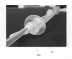
- FIG. 5 is a photograph showing the drainage lumen 39 a and the anterior nostril balloon 33.
- FIG. 6A is a photograph of each connector viewed from the proximal end side.
- the first connector that communicates with the external air communication lumen and the rear nostril balloon air supply lumen is visible on the right side.
- Visible in the center is a second connector communicating with the drainage lumen.
- the third connector communicating with the air supply lumen for the anterior nostril balloon is visible on the left side.
- FIG. 6B is an enlarged photograph showing the second connector and the third connector. The above-described on-off valve is provided inside the third connector.
- the slide mechanism includes an inner space 33a having a circular cross section formed in the anterior nostril balloon 33 and an annular rib 33b formed on the inner surface forming the inner space 33a. It has been realized.
- the internal space 33a is for the rear nostril balloon catheter 13 to pass through.
- Four ribs 33b having an inner diameter smaller than the inner diameter of the inner surface are provided.
- the inner diameter of the rib 33b is set so as to be smaller than the outer diameter of the posterior nostril balloon catheter 13, and a frictional force is generated between the rib 33b and the posterior nostril balloon catheter 13. For this reason, it is possible to reliably prevent the rear nostril balloon catheter 11 from unintentionally moving with respect to the drainage catheter 31.
- the rib 33b also exhibits a sealing function. This is because a syringe is connected to the second connector 37A of the catheter for drainage, and the piston is moved so that the inside of the sinuses between the front nostril balloon 33 and the rear nostril balloon 13 is vacuumed. This is because the sealing function is necessary to efficiently remove pus.
- the rib can also prevent pus and the like from passing between the surface of the rear nostril balloon catheter 11 and the inner surface of the front nostril balloon 33.
- the sealing function can be more reliably exhibited.
- four ribs 33b are formed in total, two at each end of the internal space 33a.
- the present invention is not limited to this, and one rib 33b is provided. May be provided, or two, three, or five or more may be provided.
- the sinusitis treatment catheter 1 is placed in the sinus 51 so that the anterior nostril balloon 33 is positioned in the anterior nostril in the sinus 51 and the posterior nostril balloon 13 is positioned in the nostril. insert. Positioning of the sinusitis treatment catheter 1 is performed while confirming the position of the contrast member. When correctly positioned, air is sent to the front nostril balloon 33 and the rear nostril balloon 13 to inflate both balloons 13 and 33. In the figure, the balloons 13 and 33 are inflated. As a result, the internal space of the paranasal sinus 51 is sealed by the two balloons.
- the syringe 53 is connected to the second connector 37A of the drainage catheter 31.
- the syringe 53 is filled with a liquid used for the treatment of sinusitis, such as a cleaning liquid or a chemical liquid.
- a cleaning liquid or the like is injected from the syringe 53.
- the washing liquid or the like is ejected from the distal end side opening 41 through the drainage lumen of the drainage catheter 31 and injected into the sinus 51.
- the pus in the sinuses 51 mixes with the cleaning liquid, and the viscosity of the pus decreases.
- the rear nostril is sealed by the rear nostril balloon 13, it is reliably prevented that the cleaning liquid or the like flows into the middle ear or the like.
- the pus softened by the cleaning liquid or the like is sucked.
- the pus in the sinuses 51 can be discharged.
- the front nostril balloon 33 and the rear nostril balloon 13 are deflated, and the sinusitis treatment catheter 1 is finally pulled out from the sinus. This completes the sinus treatment.
- the treatment time is about 10 to 15 minutes so far.
- It can be used as a sinusitis treatment catheter used for the treatment of sinuses.
Abstract
Description
図1は、本実施形態に係る副鼻腔炎治療用カテーテル1の全体外観図である。また、図2は、図1に開示した副鼻腔炎治療用カテーテル1の、各部における断面図をそれぞれ示している。当該副鼻腔炎治療用カテーテル1は、大きく分けて、後鼻孔バルーン用カテーテル11と、排膿用カテーテル31とを備えている。そして、排膿用カテーテル31の先端部が、後鼻孔バルーン用カテーテル11の中間部に結合されて一体となっている。後鼻孔バルーン用カテーテル11の先端部には、後鼻孔バルーン13が設けられている。一方、排膿用カテーテル31の先端部には、前鼻孔バルーン33が設けられている。ここで、「前」及び「後」という表現は、副鼻腔炎治療用カテーテル1の近位側(コネクタ側)を「前」と定義し、逆に副鼻腔炎治療用カテーテルの遠位側(先端側)を「後」と定義している。 [Overview]
FIG. 1 is an overall external view of a
後鼻孔バルーン用カテーテル11は、細長い本体15と、細長い本体15の遠位端に設けられた後鼻孔バルーン13と、細長い本体15の近位端に設けられた第1コネクタ17と、を備えている。また、細長い本体15の近位端の近傍には、外気連通用コネクタ18が分岐して設けられている。細長い本体15と後鼻孔バルーン13とは、シリコンゴムから形成されている。細長い本体15の内部には、図2に示すように、3本の内腔19a、19b、19cが形成されている。1本目の内腔は、外気連通用コネクタ18から遠位端の開口部21まで連通する外気連通用内腔19aである。この外気連通用内腔19aは、従来の副鼻腔炎治療用カテーテルには具備されていなかった内腔であり、仮に後鼻孔バルーン13が気道に嵌ってしまった場合でも、気道と外気とを連通させることができるようにするためのものである。なお、図2における各内空の直径は説明の便宜上のものであり、実際の直径は目的に応じて適切に設定されるものである。以下に説明する排膿用カテーテルの各内腔についても同様である。 [Catheter for rear nostril balloon]
The posterior
次に、排膿用カテーテル31について説明する。排膿用カテーテル31は、細長い本体35と、この細長い本体35の遠位端に設けられた前鼻孔バルーン33と、細長い本体35の近位端に設けられたコネクタ37とを備えている。細長い本体35と前鼻孔バルーン33とは、シリコンゴムから形成されている。細長い本体35の内部には、図2に示すように、3本の内腔39a、39b、39Cが形成されている。 [Catheter for drainage]
Next, the
11 後鼻孔バルーン用カテーテル
13 後鼻孔バルーン
15 (後鼻孔バルーン用カテーテルの)細長い本体
17 第1コネクタ
18 外気連通用コネクタ
19a 外気連通用内腔
19b 後鼻孔バルーン用送気内腔
19c (後鼻孔バルーン用カテーテルの)造影部材用内腔
21 (後鼻孔バルーン用カテーテルの)遠位端側開口部
31 排膿用カテーテル
33 前鼻孔バルーン
33b リブ
35 (排膿用カテーテルの)細長い本体
37 コネクタ
37A 第2コネクタ
37B 第3コネクタ
39a 排膿用内腔
39b 前鼻孔バルーン用送気内腔
39C (排膿用カテーテルの)造影部材用内腔
41 (排膿用カテーテルの)遠位端側開口部
51 副鼻腔
53 シリンジ DESCRIPTION OF
Claims (10)
- 前鼻孔バルーンと、この前鼻孔バルーンを膨張させる前鼻孔バルーン用送気内腔と、後鼻孔バルーンと、この後鼻孔バルーンを膨張させる後鼻孔バルーン用送気内腔と、前記前鼻腔バルーンと後鼻孔バルーンとの間に開口部を有する排膿用内腔とを備え、
前記後鼻孔バルーンよりも遠位側に開口部を有する外気連通用内腔が更に設けられていることを特徴とする、副鼻腔炎治療用カテーテル。 Anterior nostril balloon, an air supply lumen for anterior nostril balloon that inflates the anterior nostril balloon, a back nostril balloon, an air supply lumen for an after nostril balloon that inflates the nostril balloon, and the anterior nasal balloon and the rear A drainage lumen having an opening between the nostril balloon and
A sinusitis treatment catheter, further comprising an external air communication lumen having an opening on a distal side of the rear nostril balloon. - 前記前鼻孔バルーンと後鼻孔バルーンは、いずれもシリコンゴムによって形成されていることを特徴とする、請求項1に記載の副鼻腔炎治療用カテーテル。 2. The sinusitis treatment catheter according to claim 1, wherein both the anterior nostril balloon and the posterior nostril balloon are formed of silicone rubber.
- 前記外気連通用内腔は、前記後鼻孔バルーン用送気内腔に併設されていることを特徴とする、請求項1又は2に記載の副鼻腔炎治療用カテーテル。 3. The sinusitis treatment catheter according to claim 1, wherein the external air communication lumen is provided alongside the air supply lumen for the rear nostril balloon.
- 前記外気連通用内腔は、前記後鼻孔バルーンを貫通していることを特徴とする、請求項1~3の何れか一項に記載の副鼻腔炎治療用カテーテル。 The sinusitis treatment catheter according to any one of claims 1 to 3, wherein the external air communication lumen penetrates the rear nostril balloon.
- 前記後鼻孔バルーンの先端部の表面は、前記後鼻孔バルーン用送気内腔の長手方向に対して略直交していることを特徴とする、請求項1~4の何れか一項に記載の副鼻腔炎治療用カテーテル。 The surface of the distal end portion of the posterior nostril balloon is substantially orthogonal to the longitudinal direction of the air supply lumen for the posterior nostril balloon, according to any one of claims 1 to 4. Sinusitis treatment catheter.
- 前記前鼻孔バルーン用送気内腔は、前記排膿用内腔に併設されていることを特徴とする、請求項1~5の何れか一項に記載の副鼻腔炎治療用カテーテル。 The sinusitis treatment catheter according to any one of claims 1 to 5, wherein the air supply lumen for the anterior nostril balloon is provided side by side with the drainage lumen.
- 前記外気連通用内腔および後鼻孔バルーン用送気内腔は、後鼻孔バルーン用カテーテルの内部に設けられ、前記排膿用内腔と前鼻孔バルーン用送気内腔は、排膿用カテーテルの内部に設けられていることを特徴とする、請求項1~6の何れか一項に記載の副鼻腔炎治療用カテーテル。 The external air communication lumen and the posterior nostril balloon air supply lumen are provided inside the posterior nostril balloon catheter, and the drainage lumen and the anterior nostril balloon air supply lumen are included in the drainage catheter. The sinusitis treatment catheter according to any one of claims 1 to 6, wherein the catheter is provided inside.
- 前記後鼻孔バルーン用カテーテル及び排膿用カテーテルの少なくとも何れか一方には、造影部材としての針金が埋設されていることを特徴とする、請求項7に記載の副鼻腔炎治療用カテーテル。 8. The sinusitis treatment catheter according to claim 7, wherein a wire as a contrast member is embedded in at least one of the posterior nostril balloon catheter and the drainage catheter.
- 前記後鼻孔バルーンと前鼻孔バルーンの相互間距離は調整可能であることを特徴とする、請求項1~8の何れか一項に記載の副鼻腔炎治療用カテーテル。 The sinusitis treatment catheter according to any one of claims 1 to 8, wherein a distance between the posterior nostril balloon and the anterior nostril balloon is adjustable.
- 前記後鼻孔バルーンと前鼻孔バルーンの相互間距離の調整は、後鼻孔バルーン用カテーテルが通るために前鼻孔バルーンの内部に形成された断面円形の内部空間と、この内部空間の内面に形成された少なくとも1つの環状のリブによって実現される、請求項9に記載の副鼻腔炎治療用カテーテル。 The distance between the posterior nostril balloon and the anterior nostril balloon was adjusted by forming an internal space with a circular cross section formed inside the anterior nostril balloon for the passage of the catheter for the posterior nostril balloon and an inner surface of the internal space. 10. The sinusitis treatment catheter according to claim 9, realized by at least one annular rib.
Priority Applications (3)
| Application Number | Priority Date | Filing Date | Title |
|---|---|---|---|
| JP2015506538A JPWO2014147868A1 (en) | 2013-03-22 | 2013-09-09 | Sinusitis treatment catheter |
| EP13878993.8A EP2977014B1 (en) | 2013-03-22 | 2013-09-09 | Catheter for treatment of sinusitis |
| US14/779,244 US10137281B2 (en) | 2013-03-22 | 2013-09-09 | Catheter for treatment of sinusitis |
Applications Claiming Priority (2)
| Application Number | Priority Date | Filing Date | Title |
|---|---|---|---|
| JP2013-060256 | 2013-03-22 | ||
| JP2013060256 | 2013-03-22 |
Publications (1)
| Publication Number | Publication Date |
|---|---|
| WO2014147868A1 true WO2014147868A1 (en) | 2014-09-25 |
Family
ID=51579583
Family Applications (1)
| Application Number | Title | Priority Date | Filing Date |
|---|---|---|---|
| PCT/JP2013/074220 WO2014147868A1 (en) | 2013-03-22 | 2013-09-09 | Catheter for treatment of sinusitis |
Country Status (4)
| Country | Link |
|---|---|
| US (1) | US10137281B2 (en) |
| EP (1) | EP2977014B1 (en) |
| JP (2) | JPWO2014147868A1 (en) |
| WO (1) | WO2014147868A1 (en) |
Cited By (10)
| Publication number | Priority date | Publication date | Assignee | Title |
|---|---|---|---|---|
| CN104784810A (en) * | 2015-05-09 | 2015-07-22 | 无锡市人民医院 | Nasal cavity double-bag treatment pump |
| CN104783857A (en) * | 2015-05-09 | 2015-07-22 | 无锡市人民医院 | Nasal cavity double-bag adjustable pump |
| RU2663932C1 (en) * | 2017-07-21 | 2018-08-13 | Владимир Сергеевич Козлов | Device for conservative therapy of nose and paranasal sinuses diseases |
| WO2020048257A1 (en) * | 2018-09-03 | 2020-03-12 | 南微医学科技股份有限公司 | Two-balloon perfusion catheter with adjustable spacing and usage method thereof |
| WO2020060209A1 (en) * | 2018-09-19 | 2020-03-26 | (주)메가메디칼 | Balloon catheter |
| WO2020060208A1 (en) * | 2018-09-19 | 2020-03-26 | (주)메가메디칼 | Balloon catheter |
| KR20200041845A (en) * | 2020-04-02 | 2020-04-22 | (주)메가메디칼 | balloon catheter |
| KR20200041843A (en) * | 2020-04-02 | 2020-04-22 | (주)메가메디칼 | balloon catheter |
| KR20200041844A (en) * | 2020-04-02 | 2020-04-22 | (주)메가메디칼 | balloon catheter |
| KR20200041842A (en) * | 2020-04-02 | 2020-04-22 | (주)메가메디칼 | balloon catheter |
Families Citing this family (3)
| Publication number | Priority date | Publication date | Assignee | Title |
|---|---|---|---|---|
| WO2018050165A1 (en) * | 2016-09-16 | 2018-03-22 | David Spiggle | Catheter for applying a medium into the middle ear |
| CN111803729B (en) * | 2020-08-21 | 2021-03-30 | 徐定远 | Surgical suction device |
| CN111803730B (en) * | 2020-08-21 | 2022-10-21 | 徐定远 | Suction device for throat, neck and oral and maxillofacial surgery and use method thereof |
Citations (9)
| Publication number | Priority date | Publication date | Assignee | Title |
|---|---|---|---|---|
| JPS5281992A (en) * | 1975-12-29 | 1977-07-08 | Taichirou Akiyama | Airtight fluid discharging mechanism |
| JPS6458263A (en) * | 1987-08-28 | 1989-03-06 | Terumo Corp | Intravascular introducing catheter |
| JPH03503011A (en) * | 1988-06-13 | 1991-07-11 | ヤロスラフスキ メゾトラスレボイ ナウチノ‐テフニチェスキ ツェントル | Diagnosis and treatment equipment for nasal diseases |
| JPH03504935A (en) * | 1989-03-29 | 1991-10-31 | ヤロスラフスキ メゾトラスレボイ ナウチノ―テフニチェスキ ツェントル | Device for sinusitis treatment |
| WO2000009192A1 (en) * | 1998-08-17 | 2000-02-24 | Kazuhiro Noda | Operation balloon |
| JP2004008509A (en) * | 2002-06-07 | 2004-01-15 | Terumo Corp | Syringe gasket and manufacturing method therefor, and syringe |
| JP2005253538A (en) * | 2004-03-09 | 2005-09-22 | Sekisui Chem Co Ltd | Vacuum blood collection tube |
| JP2007537784A (en) * | 2004-04-21 | 2007-12-27 | アクラレント インコーポレイテッド | Apparatus, system and method for diagnosing and treating sinusitis and various diseases of the ear, nose and / or throat |
| JP2009538641A (en) * | 2006-05-19 | 2009-11-12 | ザ ファウンドリー, エルエルシー | Devices, methods and systems for nasal toxin delivery |
Family Cites Families (11)
| Publication number | Priority date | Publication date | Assignee | Title |
|---|---|---|---|---|
| US3516407A (en) | 1968-04-25 | 1970-06-23 | Santo L Ruggero | Inflatable intranasal tampon |
| US4102342A (en) | 1975-12-29 | 1978-07-25 | Taichiro Akiyama | Valved device |
| US5484412A (en) * | 1994-04-19 | 1996-01-16 | Pierpont; Brien E. | Angioplasty method and means for performing angioplasty |
| IT1304770B1 (en) * | 1998-12-03 | 2001-03-29 | Gioacchino Coppi | ENDOVASCULAR SYSTEM FOR THE TREATMENT OF ECATETERE CAROTID STENOSIS FOR SUCH SYSTEM. |
| US6231543B1 (en) * | 1999-04-15 | 2001-05-15 | Intella Interventional Systems, Inc. | Single lumen balloon catheter |
| US6443926B1 (en) * | 2000-02-01 | 2002-09-03 | Harold D. Kletschka | Embolic protection device having expandable trap |
| US7708715B2 (en) * | 2005-03-21 | 2010-05-04 | Boston Scientific Scimed, Inc. | Tissue approximation device |
| JP2012530554A (en) * | 2009-06-19 | 2012-12-06 | ベネチル・インコーポレイテッド | Device for cooling the nasal cavity |
| US9180281B2 (en) * | 2011-04-08 | 2015-11-10 | Sanovas, Inc. | Adjustable balloon catheter for extravasated drug delivery |
| US8936564B2 (en) * | 2011-08-26 | 2015-01-20 | Marshall Kerr | Bio-compatible catheter |
| WO2014035657A1 (en) * | 2012-08-28 | 2014-03-06 | Ninepoint Medical, Inc. | Endoscopic cap for catheter deployment |
-
2013
- 2013-09-09 WO PCT/JP2013/074220 patent/WO2014147868A1/en active Application Filing
- 2013-09-09 EP EP13878993.8A patent/EP2977014B1/en active Active
- 2013-09-09 JP JP2015506538A patent/JPWO2014147868A1/en active Pending
- 2013-09-09 US US14/779,244 patent/US10137281B2/en active Active
-
2018
- 2018-04-23 JP JP2018082265A patent/JP6498815B2/en active Active
Patent Citations (9)
| Publication number | Priority date | Publication date | Assignee | Title |
|---|---|---|---|---|
| JPS5281992A (en) * | 1975-12-29 | 1977-07-08 | Taichirou Akiyama | Airtight fluid discharging mechanism |
| JPS6458263A (en) * | 1987-08-28 | 1989-03-06 | Terumo Corp | Intravascular introducing catheter |
| JPH03503011A (en) * | 1988-06-13 | 1991-07-11 | ヤロスラフスキ メゾトラスレボイ ナウチノ‐テフニチェスキ ツェントル | Diagnosis and treatment equipment for nasal diseases |
| JPH03504935A (en) * | 1989-03-29 | 1991-10-31 | ヤロスラフスキ メゾトラスレボイ ナウチノ―テフニチェスキ ツェントル | Device for sinusitis treatment |
| WO2000009192A1 (en) * | 1998-08-17 | 2000-02-24 | Kazuhiro Noda | Operation balloon |
| JP2004008509A (en) * | 2002-06-07 | 2004-01-15 | Terumo Corp | Syringe gasket and manufacturing method therefor, and syringe |
| JP2005253538A (en) * | 2004-03-09 | 2005-09-22 | Sekisui Chem Co Ltd | Vacuum blood collection tube |
| JP2007537784A (en) * | 2004-04-21 | 2007-12-27 | アクラレント インコーポレイテッド | Apparatus, system and method for diagnosing and treating sinusitis and various diseases of the ear, nose and / or throat |
| JP2009538641A (en) * | 2006-05-19 | 2009-11-12 | ザ ファウンドリー, エルエルシー | Devices, methods and systems for nasal toxin delivery |
Non-Patent Citations (1)
| Title |
|---|
| See also references of EP2977014A4 * |
Cited By (21)
| Publication number | Priority date | Publication date | Assignee | Title |
|---|---|---|---|---|
| CN104784810A (en) * | 2015-05-09 | 2015-07-22 | 无锡市人民医院 | Nasal cavity double-bag treatment pump |
| CN104783857A (en) * | 2015-05-09 | 2015-07-22 | 无锡市人民医院 | Nasal cavity double-bag adjustable pump |
| JP7045771B2 (en) | 2017-07-21 | 2022-04-01 | セルゲーヴィチ コズロフ,ブラッドミア | Conservative treatment device for nasal and sinus diseases |
| WO2019017817A1 (en) * | 2017-07-21 | 2019-01-24 | Владимир Сергеевич КОЗЛОВ | Device for the conservative treatment of nasal and paranasal sinus diseases |
| JP2020529294A (en) * | 2017-07-21 | 2020-10-08 | セルゲーヴィチ コズロフ,ブラッドミア | Conservative therapy device for nasal and sinus diseases |
| RU2663932C1 (en) * | 2017-07-21 | 2018-08-13 | Владимир Сергеевич Козлов | Device for conservative therapy of nose and paranasal sinuses diseases |
| WO2020048257A1 (en) * | 2018-09-03 | 2020-03-12 | 南微医学科技股份有限公司 | Two-balloon perfusion catheter with adjustable spacing and usage method thereof |
| WO2020060209A1 (en) * | 2018-09-19 | 2020-03-26 | (주)메가메디칼 | Balloon catheter |
| WO2020060208A1 (en) * | 2018-09-19 | 2020-03-26 | (주)메가메디칼 | Balloon catheter |
| KR20200032942A (en) * | 2018-09-19 | 2020-03-27 | (주)메가메디칼 | balloon catheter |
| KR20200032941A (en) * | 2018-09-19 | 2020-03-27 | (주)메가메디칼 | balloon catheter |
| KR102209283B1 (en) * | 2018-09-19 | 2021-01-29 | (주) 메가메디칼 | balloon catheter |
| KR102209282B1 (en) * | 2018-09-19 | 2021-01-29 | (주) 메가메디칼 | balloon catheter |
| KR20200041843A (en) * | 2020-04-02 | 2020-04-22 | (주)메가메디칼 | balloon catheter |
| KR102181140B1 (en) | 2020-04-02 | 2020-11-23 | (주)메가메디칼 | balloon catheter |
| KR102181141B1 (en) | 2020-04-02 | 2020-11-23 | (주)메가메디칼 | balloon catheter |
| KR102181138B1 (en) | 2020-04-02 | 2020-11-24 | (주)메가메디칼 | balloon catheter |
| KR102181139B1 (en) | 2020-04-02 | 2020-11-24 | (주)메가메디칼 | balloon catheter |
| KR20200041842A (en) * | 2020-04-02 | 2020-04-22 | (주)메가메디칼 | balloon catheter |
| KR20200041844A (en) * | 2020-04-02 | 2020-04-22 | (주)메가메디칼 | balloon catheter |
| KR20200041845A (en) * | 2020-04-02 | 2020-04-22 | (주)메가메디칼 | balloon catheter |
Also Published As
| Publication number | Publication date |
|---|---|
| JP2018171449A (en) | 2018-11-08 |
| EP2977014A4 (en) | 2016-12-21 |
| JPWO2014147868A1 (en) | 2017-02-16 |
| US10137281B2 (en) | 2018-11-27 |
| US20160038723A1 (en) | 2016-02-11 |
| EP2977014A1 (en) | 2016-01-27 |
| JP6498815B2 (en) | 2019-04-10 |
| EP2977014B1 (en) | 2019-05-15 |
Similar Documents
| Publication | Publication Date | Title |
|---|---|---|
| JP6498815B2 (en) | Sinusitis treatment catheter | |
| US7235099B1 (en) | Sphenoid sinus stent | |
| US10456519B2 (en) | Apparatus and method for irrigating sinus cavity | |
| CN103945895B (en) | Intranasal expansion and the apparatus and method rinsed for nasal sinus | |
| FI100766B (en) | Device for treating sinusitis | |
| ES2222570T3 (en) | ASPIRATION AND IRRIGATION SYSTEM OF DEEP WOUNDS. | |
| ES2677323T3 (en) | Bushing for removable sheath assembly with hemostatic valve | |
| US20140276654A1 (en) | Nasal Suction Device | |
| MX2014012379A (en) | Devices and method for maxillary sinus lavage. | |
| WO2013146203A1 (en) | Medical treatment instrument | |
| JP2002534168A (en) | Gastric balloon catheter with improved balloon placement | |
| ES2548007T3 (en) | Endotracheal device for mechanical ventilation | |
| WO2017000582A1 (en) | Paranasal sinus dilatation flusher and usage thereof | |
| TWI653066B (en) | Tracheal tube system including tracheal tube and suction device | |
| WO2019209682A1 (en) | Systems, instruments and methods for treating sinuses | |
| CN207520343U (en) | One kind is used for the adjustable irrigation of sinuses device of surgery of nasal cavity rear nozzle | |
| WO2013146202A1 (en) | Medical treatment instrument | |
| CN105559734A (en) | Rigid endoscope used for examination and matched with balloon-shaped sheath tube | |
| CN109045430A (en) | A kind of visual trachea cannula | |
| WO2014050620A1 (en) | Medical instrument | |
| ES2652298T3 (en) | Implant device for access to the sinuses and kit | |
| CN108042894A (en) | Exempt to inflate drainage laryngeal mask tracheal catheter | |
| CN109789298A (en) | Conduit for being applied to medium in middle ear | |
| US20220110516A1 (en) | Systems, instruments and methods for treating a subject | |
| CN113081138A (en) | Nasal cavity hemostasis device and operation method thereof |
Legal Events
| Date | Code | Title | Description |
|---|---|---|---|
| 121 | Ep: the epo has been informed by wipo that ep was designated in this application |
Ref document number: 13878993 Country of ref document: EP Kind code of ref document: A1 |
|
| ENP | Entry into the national phase |
Ref document number: 2015506538 Country of ref document: JP Kind code of ref document: A |
|
| NENP | Non-entry into the national phase |
Ref country code: DE |
|
| WWE | Wipo information: entry into national phase |
Ref document number: 14779244 Country of ref document: US |
|
| WWE | Wipo information: entry into national phase |
Ref document number: 2013878993 Country of ref document: EP |