WO2014141968A1 - 内視鏡システム - Google Patents
内視鏡システム Download PDFInfo
- Publication number
- WO2014141968A1 WO2014141968A1 PCT/JP2014/055638 JP2014055638W WO2014141968A1 WO 2014141968 A1 WO2014141968 A1 WO 2014141968A1 JP 2014055638 W JP2014055638 W JP 2014055638W WO 2014141968 A1 WO2014141968 A1 WO 2014141968A1
- Authority
- WO
- WIPO (PCT)
- Prior art keywords
- image
- unit
- information
- candidate
- endoscope
- Prior art date
Links
Images


Classifications
-
- A—HUMAN NECESSITIES
- A61—MEDICAL OR VETERINARY SCIENCE; HYGIENE
- A61B—DIAGNOSIS; SURGERY; IDENTIFICATION
- A61B1/00—Instruments for performing medical examinations of the interior of cavities or tubes of the body by visual or photographical inspection, e.g. endoscopes; Illuminating arrangements therefor
- A61B1/00002—Operational features of endoscopes
- A61B1/00004—Operational features of endoscopes characterised by electronic signal processing
- A61B1/00009—Operational features of endoscopes characterised by electronic signal processing of image signals during a use of endoscope
-
- A—HUMAN NECESSITIES
- A61—MEDICAL OR VETERINARY SCIENCE; HYGIENE
- A61B—DIAGNOSIS; SURGERY; IDENTIFICATION
- A61B1/00—Instruments for performing medical examinations of the interior of cavities or tubes of the body by visual or photographical inspection, e.g. endoscopes; Illuminating arrangements therefor
- A61B1/00002—Operational features of endoscopes
- A61B1/0002—Operational features of endoscopes provided with data storages
-
- A—HUMAN NECESSITIES
- A61—MEDICAL OR VETERINARY SCIENCE; HYGIENE
- A61B—DIAGNOSIS; SURGERY; IDENTIFICATION
- A61B1/00—Instruments for performing medical examinations of the interior of cavities or tubes of the body by visual or photographical inspection, e.g. endoscopes; Illuminating arrangements therefor
- A61B1/00002—Operational features of endoscopes
- A61B1/00043—Operational features of endoscopes provided with output arrangements
- A61B1/00045—Display arrangement
- A61B1/0005—Display arrangement combining images e.g. side-by-side, superimposed or tiled
-
- A—HUMAN NECESSITIES
- A61—MEDICAL OR VETERINARY SCIENCE; HYGIENE
- A61B—DIAGNOSIS; SURGERY; IDENTIFICATION
- A61B1/00—Instruments for performing medical examinations of the interior of cavities or tubes of the body by visual or photographical inspection, e.g. endoscopes; Illuminating arrangements therefor
- A61B1/00147—Holding or positioning arrangements
-
- A—HUMAN NECESSITIES
- A61—MEDICAL OR VETERINARY SCIENCE; HYGIENE
- A61B—DIAGNOSIS; SURGERY; IDENTIFICATION
- A61B1/00—Instruments for performing medical examinations of the interior of cavities or tubes of the body by visual or photographical inspection, e.g. endoscopes; Illuminating arrangements therefor
- A61B1/267—Instruments for performing medical examinations of the interior of cavities or tubes of the body by visual or photographical inspection, e.g. endoscopes; Illuminating arrangements therefor for the respiratory tract, e.g. laryngoscopes, bronchoscopes
- A61B1/2676—Bronchoscopes
-
- G—PHYSICS
- G06—COMPUTING; CALCULATING OR COUNTING
- G06T—IMAGE DATA PROCESSING OR GENERATION, IN GENERAL
- G06T19/00—Manipulating 3D models or images for computer graphics
- G06T19/003—Navigation within 3D models or images
-
- A—HUMAN NECESSITIES
- A61—MEDICAL OR VETERINARY SCIENCE; HYGIENE
- A61B—DIAGNOSIS; SURGERY; IDENTIFICATION
- A61B1/00—Instruments for performing medical examinations of the interior of cavities or tubes of the body by visual or photographical inspection, e.g. endoscopes; Illuminating arrangements therefor
- A61B1/04—Instruments for performing medical examinations of the interior of cavities or tubes of the body by visual or photographical inspection, e.g. endoscopes; Illuminating arrangements therefor combined with photographic or television appliances
- A61B1/05—Instruments for performing medical examinations of the interior of cavities or tubes of the body by visual or photographical inspection, e.g. endoscopes; Illuminating arrangements therefor combined with photographic or television appliances characterised by the image sensor, e.g. camera, being in the distal end portion
-
- A—HUMAN NECESSITIES
- A61—MEDICAL OR VETERINARY SCIENCE; HYGIENE
- A61B—DIAGNOSIS; SURGERY; IDENTIFICATION
- A61B34/00—Computer-aided surgery; Manipulators or robots specially adapted for use in surgery
- A61B34/20—Surgical navigation systems; Devices for tracking or guiding surgical instruments, e.g. for frameless stereotaxis
- A61B2034/2046—Tracking techniques
- A61B2034/2065—Tracking using image or pattern recognition
-
- A—HUMAN NECESSITIES
- A61—MEDICAL OR VETERINARY SCIENCE; HYGIENE
- A61B—DIAGNOSIS; SURGERY; IDENTIFICATION
- A61B5/00—Measuring for diagnostic purposes; Identification of persons
- A61B5/06—Devices, other than using radiation, for detecting or locating foreign bodies ; determining position of probes within or on the body of the patient
- A61B5/065—Determining position of the probe employing exclusively positioning means located on or in the probe, e.g. using position sensors arranged on the probe
-
- A—HUMAN NECESSITIES
- A61—MEDICAL OR VETERINARY SCIENCE; HYGIENE
- A61B—DIAGNOSIS; SURGERY; IDENTIFICATION
- A61B6/00—Apparatus for radiation diagnosis, e.g. combined with radiation therapy equipment
- A61B6/02—Devices for diagnosis sequentially in different planes; Stereoscopic radiation diagnosis
- A61B6/03—Computerised tomographs
- A61B6/032—Transmission computed tomography [CT]
-
- A—HUMAN NECESSITIES
- A61—MEDICAL OR VETERINARY SCIENCE; HYGIENE
- A61B—DIAGNOSIS; SURGERY; IDENTIFICATION
- A61B6/00—Apparatus for radiation diagnosis, e.g. combined with radiation therapy equipment
- A61B6/52—Devices using data or image processing specially adapted for radiation diagnosis
- A61B6/5211—Devices using data or image processing specially adapted for radiation diagnosis involving processing of medical diagnostic data
- A61B6/5223—Devices using data or image processing specially adapted for radiation diagnosis involving processing of medical diagnostic data generating planar views from image data, e.g. extracting a coronal view from a 3D image
-
- G—PHYSICS
- G06—COMPUTING; CALCULATING OR COUNTING
- G06T—IMAGE DATA PROCESSING OR GENERATION, IN GENERAL
- G06T2210/00—Indexing scheme for image generation or computer graphics
- G06T2210/41—Medical
Definitions
- the present invention relates to an endoscope system for imaging an inside of a subject with an imaging means.
- endoscopes having an insertion portion that can be inserted into a body cavity or the like have been widely used in the medical field and the like.
- it is inserted into a luminal organ that branches in a complicated manner like the bronchus in the body cavity, and the target site (affected tissue) on the terminal side of the luminal organ is examined, or a biopsy or treatment using a treatment instrument is performed.
- it may be difficult to introduce the distal end of the insertion portion up to the vicinity of the target site only with the endoscopic image obtained upon insertion.
- an endoscope image as an observation image obtained by an endoscope and image data of a three-dimensional region of the bronchus are generated.
- an image synthesizing unit that superimposes and displays a virtual endoscopic image, a virtual endoscopic schematic diagram image, and the like on the endoscopic image;
- An image correction unit for matching the directions is disclosed.
- the content is generated based on the endoscopic image acquired by the imaging unit of the endoscope and the three-dimensional image data of the bronchus. It has been difficult to estimate the position of the distal end of the endoscope insertion portion by comparing the image with the virtual endoscopic image. More specifically, the three-dimensional position of the distal end of the endoscope insertion unit corresponds to the CT coordinate system or the CT coordinate system after being aligned with the CT coordinate system used when generating the virtual endoscopic image. It is managed by the attached coordinate system.
- the three-dimensional position of the tip of the endoscope insertion portion is changed from the three-dimensional position by the CT coordinate system due to disturbance or the like. It often happens that they are displaced. In such a case, it is necessary to set the distal end of the endoscope insertion portion to a known reference position such as a carina in the bronchus and perform realignment (realignment).
- candidate position information as candidate information of a position acquired until reaching and a virtual endoscopic image corresponding to the candidate position information are presented as candidate information on a three-dimensional or two-dimensional tomographic image of the bronchus. It is.
- the above conventional example does not disclose the contents of such presentation.
- the present invention has been made in view of the above points, and candidate information suitable for re-alignment in a case where a shift between both positions in which an endoscopic image and a virtual endoscopic image are generated has occurred.
- An object of the present invention is to provide an endoscope system capable of presenting.
- An endoscope system includes an image storage unit that stores three-dimensional image information of a subject acquired in advance, and the three-dimensional image information is drawn endoscopically from a predetermined viewpoint position.
- a virtual endoscopic image generation unit that generates a virtual endoscopic image, an imaging unit that is provided in the endoscope and images the inside of the predetermined lumen organ, and a predetermined lumen organ of the subject
- a position detection unit for detecting the position of the distal end of the endoscope insertion unit, and a two-dimensional tomographic image obtained by cutting out the three-dimensional image information in a predetermined direction based on position information of the distal end of the endoscope insertion unit by the position detection unit
- candidate position information that is a candidate for performing image comparison between the virtual endoscopic image and an endoscopic image generated by imaging of the imaging unit, and the virtual endoscope corresponding to the candidate position information
- Candidate information presentation that presents mirror image as candidate information And, equipped with a.
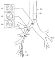
- FIG. 1 is a diagram showing an overall configuration of an endoscope system according to a first embodiment of the present invention.
- FIG. 2A is a diagram showing a bronchial shape image.
- FIG. 2B is a diagram showing a distance range of a constant value from a spar in a bronchial shape image.
- FIG. 2C is a diagram showing a constant distance range from a branch point in a bronchial shape image.
- FIG. 2D is a diagram showing a presentation example of candidate information.
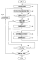
- FIG. 3 is a flowchart showing a representative example of processing contents of the first embodiment.
- FIG. 4 is a diagram showing a route that is a distance from a branch point along the core line.
- FIG. 4 is a diagram showing a route that is a distance from a branch point along the core line.
- FIG. 5A is a diagram illustrating an overall configuration of an endoscope system according to a modification of the first embodiment.
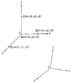
- FIG. 5B is an explanatory diagram of registration as a process of associating two coordinate systems.
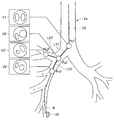
- FIG. 6 is an explanatory diagram of the operation in the second embodiment of the present invention.
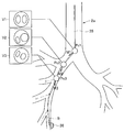
- FIG. 7 is an explanatory diagram of the operation in the third embodiment of the present invention.
- FIG. 8 is an explanatory diagram of an operation in a modification of the third embodiment.
- FIG. 9 is an explanatory diagram of an operation for storing candidate information from changes in an endoscopic image.
- FIG. 10A is a diagram showing a presentation example of candidate information different from FIG. 2D.
- FIG. 10B is a diagram showing a presentation example of candidate information different from FIG. 10A.
- FIG. 10C is a diagram showing a presentation example of candidate information different from FIG. 10A.
- FIG. 10D is a diagram showing a presentation example of candidate information different from FIG. 10A.
- FIG. 10E is a diagram showing a presentation example of candidate information different from FIG. 10A.
- FIG. 10F is a diagram showing a presentation example of candidate information different from FIG. 10A.
- FIG. 10G is a diagram showing a presentation example of candidate information different from FIG. 10A.
- FIG. 11 is a diagram showing an example of displaying an estimated position on a tomographic image including a bronchus.
- FIG. 12 is a diagram showing an example in which each position and the corresponding VBS in FIG. 11 are associated with character information.
- FIG. 12 is a diagram showing an example in which each position and the corresponding VBS in FIG. 11 are associated with character information.
- FIG. 13 is a view showing a display example corresponding to the modification of FIG.
- FIG. 14 is a diagram showing a display example in which the moving direction is further displayed in FIG.
- FIG. 15 is a diagram showing a display example that further displays the visual field range in FIG.
- FIG. 16 is a diagram showing a display example in which the visual field range is also displayed three-dimensionally on one tomographic image.
- FIG. 17 is a diagram illustrating an example of displaying a stored position in an area.
- FIG. 18 is a diagram illustrating an example in which a bronchial tree and a tomographic image are superimposed and displayed.
- FIG. 19 is a diagram showing an example of display using two tomographic images.
- FIG. 20 is a diagram illustrating an example of display on a cut surface including a bronchial tree at a stored position.
- FIG. 21 is an explanatory diagram of the setting method of FIG.
- the endoscope system 1 As shown in FIG. 1, the endoscope system 1 according to the first embodiment of the present invention is inserted into a bronchus 2 (FIG. 2A) as a predetermined luminal organ in a patient as a subject to be examined.
- An endoscope apparatus 4 including the endoscope 3 and an insertion support apparatus 5 that is used together with the endoscope apparatus 4 and supports the insertion of the endoscope 3 are mainly configured.
- the endoscope apparatus 4 performs signal processing on the endoscope 3, a light source device 6 that supplies illumination light to the endoscope 3, and an image sensor 7 that constitutes an imaging unit mounted on the endoscope 3. It has a camera control unit (abbreviated as CCU) 8 as a signal processing device, and a monitor 9 for displaying an endoscopic image generated by the CCU 8.
- CCU camera control unit
- the endoscope 3 includes an elongated insertion portion (or endoscope insertion portion) 11 having flexibility, and an operation portion 12 provided at the rear end of the insertion portion 11.
- the part 13 is provided with an illumination window and an observation window.
- a light guide 14 that transmits illumination light is inserted into the insertion unit 11 and the operation unit 12, and an incident end of the light guide 14 is connected to the light source device 6 and is generated by a light source lamp or LED (not shown) in the light source device 6. The illuminated light is incident on the incident end.
- the illumination light transmitted by the light guide 14 is emitted forward from an emission end (tip surface) attached to the illumination window.
- an objective lens 15 that forms an objective optical system that forms an image of a subject is attached to the observation window, and an imaging element 7 such as a CCD is disposed at the imaging position, and the objective lens 15 and the imaging element 7
- An imaging device 16 is formed as an imaging means (or imaging unit) that images the bronchus 2 as a predetermined luminal organ into which the insertion unit 11 is inserted.
- the image sensor 7 is connected to the CCU 8 through a signal line inserted through the insertion unit 11 and the operation unit 12.
- the CCU 8 generates an image signal of a captured image corresponding to an optical image formed on the imaging surface of the image sensor 7 by an image signal generation circuit (not shown) therein, and outputs the image signal to the monitor 9.
- the monitor 9 displays an image (moving image) of the image signal as an endoscopic image (also referred to as a captured image).
- the insertion portion 11 of the endoscope 3 is provided with a bendable bending portion 19 at the rear end of the distal end portion 13, and the operator performs an operation of rotating a bending operation knob 20 provided on the operation portion 12.
- the bending portion 19 can be bent in any direction, up and down, left and right.
- the insertion support device 5 uses, as a DVD, a Blu-ray disc, a flash, and CT data as three-dimensional image information of a patient generated by known CT (Computed Tomography) for a patient to be examined by the endoscope 3. It has CT data acquisition part 21 taken in via portable storage media, such as memory, and CT image data storage part 22 which memorizes CT data taken in by this CT data acquisition part 21.
- CT data acquisition part 21 taken in via portable storage media, such as memory
- CT image data storage part 22 which memorizes CT data taken in by this CT data acquisition part 21.
- the CT image data storage unit 22 may store CT data (as 3D image information of a patient as a subject) generated by CT via a communication line, the Internet, or the like.
- the CT image data storage unit 22 can be configured by a hard disk device, a flash memory, a DVD, or the like.
- the CT image data storage unit 22 constituting the image storage means includes a CT image data obtained by separating image data from the CT data, and a first coordinate system corresponding to the CT image data obtained by separating position information from the CT data. It has the matching image information storage part 22a memorize
- the insertion support device 5 includes a lumen organ extraction circuit serving as a lumen organ extraction unit that extracts three-dimensional image data of the bronchus 2 as a predetermined lumen organ from the CT image data in the CT image data storage unit 22.
- a bronchus extraction unit 23 including an arithmetic processing unit (abbreviated as CPU) is provided.
- the bronchus extraction unit 23 obtains 3D shape information (shape data) representing the hollow shape of the bronchus 2 and 3D shape from the extracted 3D data (more specifically, 3D volume data) of the bronchi 2. Image information (image data) is generated. That is, the bronchi extraction unit 23 includes a bronchial shape image generation unit 23a as a bronchial shape image generation unit that generates a bronchial shape image as a hollow three-dimensional bronchial shape image from the extracted three-dimensional data of the bronchi 2. .
- the bronchi extracting unit 23 extracts the three-dimensional position data in the first coordinate system (or CT coordinate system) corresponding to the three-dimensional data in association with the three-dimensional data.
- the bronchus extraction unit 23 includes an association information storage unit 23b including a memory that stores association information in which 3D shape data of the bronchi 2 (that is, bronchial shape data) and 3D position data are associated with each other.
- the insertion support device 5 is a virtual internal as a virtual endoscopic image corresponding to an endoscopic image generated by imaging with the imaging device 16 provided at the distal end portion 13 of the insertion portion 11 in the endoscope 3.
- a VBS image generation unit 24 is provided as virtual endoscopic image generation means for generating an endoscopic image (referred to as a VBS image).
- the VBS image generation unit 24 receives imaging system characteristic information (the focal length of the objective lens 15, the number of pixels of the image sensor 7, the pixel size, etc.) related to the imaging device 16 of the endoscope 3 from, for example, the input device 31. Is done.
- the VBS image generation unit 24 includes information on the position of the imaging device 16 of the endoscope 3 that is actually inserted into the bronchus 2 (also referred to as the position of the tip of the insertion unit 11), and the subject in the bronchus 2 by the imaging device 16 Generation for generating a VBS image for virtually drawing an endoscopic image obtained by endoscopically imaging the inside of the bronchus 2 with the position as a viewpoint position based on the characteristic information for imaging the image and the bronchial shape data A circuit, a CPU, and the like are included.
- the insertion support apparatus 5 also includes an image processing unit 25 configured by a CPU, an image processing circuit, and the like that perform image matching between the endoscopic image input from the CCU 8 and the VBS image of the VBS image generation unit 24.
- an image processing unit 25 configured by a CPU, an image processing circuit, and the like that perform image matching between the endoscopic image input from the CCU 8 and the VBS image of the VBS image generation unit 24.
- a storage unit 27 including a memory or the like.
- the insertion support device 5 includes an MPR image generation unit 28 that generates a CT tomographic image (referred to as an MPR image) as a multi-section reconstructed image based on the CT image data stored in the CT image data storage unit 22, and an MPR image A pointing device such as a mouse that generates a path setting screen as an insertion path setting screen having an MPR image generated by the generating unit 28 and sets a path for insertion into the target site in the bronchus 2 of the endoscope 3 And a route setting unit 29.
- MPR image generation unit 28 that generates a CT tomographic image (referred to as an MPR image) as a multi-section reconstructed image based on the CT image data stored in the CT image data storage unit 22, and an MPR image A pointing device such as a mouse that generates a path setting screen as an insertion path setting screen having an MPR image generated by the generating unit 28 and sets a path for insertion into the target site in the bronchus 2 of the endoscope 3
- the path setting unit 29 inserts (in the insertion unit 11) in the bronchus 2 from the CT image data and the bronchial shape image 2a. It has a function of a route data generation unit 29a such as a route data generation circuit that generates route data from a start position to a target position near the target region 36.
- a route data generation unit 29a such as a route data generation circuit that generates route data from a start position to a target position near the target region 36.
- a path to a target position near the target portion 36 is indicated by R.
- the endoscope system 1 further includes an input device 31 including a keyboard and a pointing device for inputting setting information to the route setting unit 29. Further, the surgeon can input parameters and data when performing image processing from the input device 31 to the image processing unit 25, and can select and instruct the control operation to the control unit 26. .
- the route setting unit 29 sends information on the set route to the VBS image generation unit 24, the MPR image generation unit 28, and the control unit 26.
- the VBS image generation unit 24 and the MPR image generation unit 28 generate a VBS image and an MPR image along the route, respectively, and the control unit 26 controls the operation of each unit along the route.
- the image processing unit 25 receives an endoscopic image generated by the CCU 8 and a VBS image generated by the VBS image generation unit 24.
- the bronchial shape image generated by the bronchial shape image generating unit 23 a is also input to the image processing unit 25.
- the alignment processing unit 25a by the image processing unit 25 is installed.
- the three-dimensional position of the tip of the insertion portion 11 is estimated (or calculated) by image matching at.
- a three-dimensional position (known position) that can be specified from the bronchial shape image 2a by the CT coordinate system, such as the entrance of the bronchus 2 or the carina K (see FIG. 2A), or its neighboring position is set as a moving image matching start position.
- the VBS image generation unit generates a VBS image based on the position information.
- the operator inserts the distal end of the insertion portion 11 so that the endoscopic image looks the same as the VBS image.
- the alignment processing unit 25a of the image processing unit 25 matches the endoscope image and the VBS image under the set conditions (within an error that can ensure a predetermined accuracy). Start image matching.
- the alignment processing unit 25a has a function of a position estimation unit 25b that detects or calculates the position of the distal end of the insertion unit 11 by estimation.
- a position estimation unit 42b that provides a position sensor 41 for position detection at the distal end portion 13 and detects (estimates) the three-dimensional position of the distal end of the insertion portion 11 using the position sensor 41 as in a modification shown in FIG. May be configured.
- the distal end of the insertion portion 11 is used in the same meaning as the distal end of the endoscope 3.
- the image processing unit 25 generates an image to be displayed on the monitor 32 under the control of the display control unit 26 a that controls display in the control unit 26. Under the control of the display control unit 26 a, the image processing unit 25 normally outputs the image signal (video signal) of the bronchial shape image 2 a generated by the bronchial shape image generation unit 23 a to the monitor 32.
- the bronchial shape image 2a is displayed as a two-dimensional tomographic image cut out in a cross section along the direction passing through the center of the (main) lumen, for example.
- the display is not limited to a two-dimensional tomographic image, and a three-dimensional image may be displayed.
- a three-dimensional image for example, it may be displayed in a projection view by a parallel projection method or in a perspective view so that the inside of the lumen can be seen.
- a core line 35 passing through the center of the lumen of the bronchus 2 is also displayed on the bronchial shape image 2 a displayed on the monitor 32.
- the core wire 35 is generated by, for example, the bronchial shape image generation unit 23a, but the image processing unit 25 may generate the core wire 35.
- the core wire 35 is displayed. Therefore, the insertion operation of the insertion portion 11 can be easily performed by referring to the display. . Further, by performing an operation of inserting along the core wire 35, the position of the distal end of the insertion portion 11 by image matching can be estimated in a short time.
- the image processing unit 25 uses the matching (image matching) of both the endoscopic image and the VBS image under the CT coordinate system in the operation of inserting into the deep side (terminal side) of the bronchus 2. A process for estimating the moved position or moving distance of the distal end of the insertion portion 11 is performed. That is, when both images match at a certain position, the imaging device 16 moves in accordance with an operation of moving the distal end of the insertion portion 11 along the core line 35 (for insertion). Changes.
- the alignment processing unit 25a uses the VBS image (output from the VBS image generation unit 24) when it moves on the route along the core line 35 to best match the endoscopic image. Is selected by image processing, and the three-dimensional position corresponding to the selected VBS image is calculated (estimated) as the position of the tip of the insertion unit 11. Therefore, the moved movement distance can also be calculated (estimated) from the difference between the two positions. Note that the distal end of the insertion unit 11 may be moved at a position deviated from the core wire 35. Therefore, the VBS image generation unit 24 generates a VBS image at a position eccentric from the core wire 35 by an appropriate distance. The processed VBS image may be output to the alignment processing unit 25a.
- the control unit 26 corrects the route data generated by the route data generation unit 29a (before insertion of the insertion unit 11 of the endoscope 3) by the position of the distal end of the insertion unit 11 calculated by the alignment processing unit 25a. You may make it do.
- control unit 26 has a function of a condition determination unit 26c configured by a comparison circuit or the like that determines whether or not the distal end of the insertion unit 11 estimated by the image processing unit 25 satisfies a predetermined condition.
- a condition determination unit 26c configured by a comparison circuit or the like that determines whether or not the distal end of the insertion unit 11 estimated by the image processing unit 25 satisfies a predetermined condition.
- the position of the tip of the corresponding insertion unit 11 is stored in the storage unit 27.
- the VBS image corresponding to the position of the distal end is stored in the storage unit 27 as candidate information to be presented (for presentation) when presentation is necessary.
- the storage unit 27 is a candidate for the case where the position of the distal end of the insertion unit 11 estimated (calculated) when the determination result is obtained is presented later.
- the candidate information storage unit 27a functions as a storage unit that stores the position information and stores the candidate position information and a VBS image corresponding to the candidate position information as candidate information for presentation.
- the candidate information for presentation includes candidate position information (candidate position information) and a VBS image corresponding to the candidate position information, but corresponds to the candidate position information (in other words, at the candidate position).
- the generated VBS image may also be a candidate VBS image.
- the image processing unit 25 is controlled by the candidate information presentation control unit 26b of the display control unit 26a, and the candidate information generation unit 25c generates candidate information to be displayed on the monitor 32 as candidate information. It has a function.
- the image processing unit 25 temporarily stores an endoscopic image and a VBS image when performing image matching between an endoscopic image and a VBS image, or an image memory 25d used as a work area for image processing. Have.
- An image memory 25d may be provided outside the image processing unit 25.
- the condition determination unit 26c functions as a predetermined region to determine whether or not the distal end of the insertion unit 11 is located in a feature region as a characteristic region related to bifurcation in the bronchi 2 as a predetermined condition. Have Then, as will be described later, in the case where the feature region determination unit 26d determines that the tip of the insertion unit 11 is located (or exists) in the feature region, candidate information is stored in the candidate information storage unit 27a.
- a constant value dth is set for the distance between two positions (or points). And between the position of the front-end
- the setting of the feature region and the value of the constant value dth can be designated by the surgeon from the input device 31, for example.
- candidate information before the current position of the distal end of the insertion unit 11 is stored in the storage unit 27.
- the position estimation accuracy (using image matching) of the tip of the insertion unit 11 is reduced by the movement operation of the insertion unit 11, and re-alignment (that is, re-alignment) is performed.
- the candidate information for the realignment can be presented.
- the operator may input an instruction to perform realignment to the image processing unit 25 or the control unit 26 from a keyboard, a mouse, or the like constituting the input device 31.
- the display control unit 26a of the control unit 26 displays candidate information near the tip position of the current insertion unit 11 as a candidate information storage unit 27a of the storage unit 27. From which the candidate information is presented on the monitor 32 via the image processing unit 25.
- the display control unit 26a that performs control for presenting candidate information on the monitor 32 has a function of a candidate information presentation control unit 26b that performs control of candidate information presentation. Note that the display control unit 26a may read out candidate information (for presentation) from the candidate information storage unit 27a and perform control to display the candidate information on the monitor 32 without passing through the image processing unit 25.
- the candidate information When the candidate information is presented on the monitor 32, for example, information on candidate positions when performing image comparison on the bronchial shape image 2a shown in FIG. 2D as a two-dimensional tomographic image and VBS corresponding to the information on the candidate positions. Display an image.
- the alignment processing unit 25a of the image processing unit 25 estimates (calculates) the distal end of the insertion unit 11 using image matching when the distal end of the insertion unit 11 is moved. There may be an image matching error that makes it impossible to perform image matching within accuracy. In this case, the alignment processing unit 25a of the image processing unit 25 generates an image matching error signal and displays on the monitor 32 that the image matching error has occurred. The alignment processing unit 25 a sends an image matching error signal to the control unit 26, and the candidate information presentation control unit 26 b of the control unit 26 performs control for presenting candidate information on the monitor 32. For this reason, the monitor 32 forms candidate information presenting means for presenting candidate information to the surgeon.
- the candidate information presenting means includes a candidate information storage unit 27a for storing candidate information (for presentation), an image processing unit 25 for outputting an image signal of candidate information, and a candidate information presentation control unit 26b together with the monitor 32. It may be defined as The surgeon performs the alignment process again using the candidate information. By performing the alignment process again, the surgeon can continue the insertion operation of the insertion portion 11 from the vicinity of the position where the alignment process is performed again. If the surgeon determines that the accuracy of the image matching has deteriorated, the above processing may be performed by instructing realignment.
- the alignment processing unit 25a, candidate information generation unit 25c, bronchus extraction unit 23, VBS image generation unit 24, and control unit 26 of the image processing unit 25 in FIG. 1 may be configured using a CPU or FPGA ( A hardware device such as a field programmable gate array) or a dedicated electronic circuit element may be used.
- the endoscope system 1 having such a configuration includes a CT image data storage unit 22 as image storage means for storing 3D image information of a subject acquired in advance, and a predetermined viewpoint position with respect to the 3D image information.
- a VBS image generating unit 24 as a virtual endoscopic image generating means for generating a virtual endoscopic image drawn endoscopically from, and the endoscope 3 is provided to image the inside of the predetermined lumen organ
- An imaging device 16 serving as an imaging unit
- a position estimation unit 25b serving as a position detection unit that detects the position of the distal end of the endoscope insertion unit 11 within a predetermined lumen organ of the subject, and the position detection unit
- a monitor 32 as candidate information presenting means for presenting the virtual endoscopic image
- the alignment processing unit 25 a of the image processing unit 25 outputs the VBS image (image signal thereof) of the VBS image generation unit 24 at the reference position to the monitor 32.
- the surgeon designates one of the reference positions from the input device 31, inserts the tip of the insertion unit 11 into the designated reference position, and performs alignment processing on the alignment processing unit 25a of the image processing unit 25. Instruct to do.
- the alignment processing unit 25a estimates (calculates) the position of the tip of the insertion unit 11 by image matching based on the result of the alignment process. Specifically, using the alignment information as an initial value of image matching, a VBS image that best matches the endoscopic image is calculated by image processing.
- step S3 the alignment processing unit 25a determines whether or not the tip of the insertion unit 11 can be estimated within a predetermined condition by image matching (for example, whether the estimated position is inside the bronchus) (that is, whether the position is successfully estimated). Is determined. If the determination in step S3 is successful, the position of the distal end of the insertion unit 11 estimated by the position estimation unit 25b of the image processing unit 25 is displayed on the monitor 32 at the estimated position on the bronchial shape image 2a. While being displayed superimposed, the process of step S4 is performed. On the other hand, if the determination is unsuccessful, the process of step S6 is executed.
- step S4 The position information of the tip of the insertion unit 11 estimated by the position estimation unit 25b in step S4 is input to the feature region determination unit 26d of the control unit 26. Then, the feature region determination unit 26d is located in the feature region in which the estimated position of the distal end of the insertion unit 11 is within a certain value dth (such as dth1, dth2) from the spur Spi and the branch point Bi in the bronchus 2. It is determined whether or not.
- step S4 in the case of a determination result that is within a certain value dth, candidate information is stored in the storage unit 27 as shown in step S5. For example, as shown in FIG.
- step S5 when the distal end of the insertion portion 11 is inserted deeper than the carina K and the distal end P2 of the insertion portion 11 falls within a predetermined value dth1 from the next spur Sp2, the estimated distal end of the insertion portion 11 is inserted.
- the position P2 becomes the candidate position Pc2, and the corresponding VBS image I2 is stored in the storage unit 27 as candidate information together with the candidate position Pc2.
- step S8 After the process of step S5, it is reflected in the process of step S8.
- the process of step S8 is executed without performing the process of recording candidate information in step S5.
- FIG. 2B shows an example in which the candidate position Pci is stored when it is determined that it is within the predetermined value dth1 from the spur Spi.
- the estimated distal end of the insertion portion 11 is branched.
- FIG. 2C shows a case where the distal ends P1 ′ and P2 ′ of the insertion portion 11 are within a certain value dth2 from the branch points B1 and B2.
- the constant value dth1 and the constant value dth2 may be set to the same value or different values.
- step S8 it is detected whether the surgeon has generated an instruction signal (trigger) for presenting candidate information from the input device 31. If it is not possible to detect that the image matching estimation has failed, for example, if the endoscope moves suddenly, the estimated position by image matching satisfies the predetermined condition (whether it is inside the bronchus). In the case of another position, an instruction signal is generated when the surgeon determines that the alignment is performed again.
- an instruction signal is generated when the surgeon determines that the alignment is performed again.
- the position estimation unit 25b determines (estimates) whether or not the distal end of the insertion unit 11 has been inserted to the target position.
- the surgeon refers to the display displayed on the monitor 32 and moves the distal end of the insertion portion 11 to the deep side of the bronchus 2 as shown in step S10. Insert into.
- the process returns to step S2 to estimate the tip position of the insertion unit 11, but the initial value of image matching uses the estimated position of the previous image matching instead of the alignment information.
- the target position is inserted in step S19, the insertion operation in FIG. 3 is terminated.
- step S6 the display control unit 26a automatically generates an instruction signal for presenting candidate information.
- candidate information is read from candidate information storage part 27a of storage part 27. And candidate information is displayed on the monitor 32 as shown to step S7.
- candidate position Pc2 stored in the information storage unit 27a
- VBS image I2 corresponding to the candidate position Pc2
- a VBS image corresponding to the candidate position Pc2 is displayed as candidate information together with the candidate position Pc2.
- an endoscopic image corresponding to the candidate position Pc2 may also be displayed as indicated by a dotted line.
- VBS image or the endoscopic image may be displayed movably, and the user may be able to superimpose and display (composite display) one image on the other image with a mouse or the like. This makes it easier for the user to check the degree of image matching.
- 2D shows an example of presentation of one candidate information, a plurality of candidate information may be presented as shown in FIGS. 10A to 10F described later. When the candidate information is displayed, the process returns to step S1, and the surgeon performs the alignment process again with reference to the candidate information displayed on the monitor 32.
- candidate information for presentation is stored in the storage unit 27 while the operator performs an operation of inserting the insertion unit 11, and the tip of the insertion unit 11 is stored.
- the position estimation is unsuccessful, the candidate information for presentation suitable for alignment can be presented as candidate information, so that the insertion operation can be performed smoothly.
- the position of the tip of the insertion portion 11 is estimated using image processing for image matching, so that the error gradually increases from the initial alignment state by the image processing algorithm. It becomes easy. Even in such a case, it is possible to perform the operation of insertion from the vicinity of the re-aligned position to the deeper side by reducing the error sufficiently by re-aligning by re-image matching.
- the conditions in the above description may be changed as follows.
- Candidate information (for presentation) is stored in the storage unit 27 when the estimated position of the tip of the insertion unit 11 satisfies one condition within a predetermined value dth1 or dth2 from the spur Spi or the branch point Bi, respectively.
- (B) Candidate information may be stored when the estimated position of the tip of the insertion portion 11 satisfies two conditions that are within the constant values dth1 and dth2 from the spur Spi and the branch point Bi, respectively.
- candidate information may be stored when the estimated distance between the distal end of the insertion portion 11 and the core wire 35 is within a predetermined value dth3.
- candidate information may be stored when a branch image is seen in the endoscopic image.
- the constant values dth1 to dth3 may be set to the same value, or the bronchi at the spur Spi or the branch point Bi. You may set according to the distance to the value according to a diameter, the branch site
- F Further, in the examples of FIGS. 2B and 2C, the case where the condition for storing is determined depending on whether the linear distance between the two points is within a certain value or not is shown. However, as shown in FIG.
- the candidate information is stored depending on whether or not the point P on the core line 35 closest to the position and the path (distance measured along the core line 35) dw on the core line 35 to the branch point Bi is within a predetermined value dwth. It is good as a condition.
- FIG. 5A shows a configuration of an endoscope system 1B according to a modification example of the first embodiment.
- An endoscope system 1B shown in FIG. 5A is similar to the endoscope system 1 of FIG.
- a position sensor 41 for detecting the position is provided.
- measurement processing that performs processing for measuring (detecting) a three-dimensional position (also simply referred to as a position) of the position sensor 41 at a predetermined position in the insertion support apparatus 5 outside the endoscope 3 and the subject.
- An apparatus or measurement processing unit 42 is provided.
- a detection signal from the position sensor 41 is input to the measurement processing unit 42.
- This measurement processing unit 42 uses the position sensor 41 to provide a three-dimensional position of the imaging device 16 that constitutes an imaging means inserted into the bronchus 2 as a predetermined luminal organ, or a three-dimensional position of the distal end of the insertion unit 11. It has the function of the position estimation part 42b as a position detection means to detect or estimate. Note that FIG. 5A of this modification does not include the position estimation unit 25b in the image processing unit 25 in FIG. As a means or method for position detection (position estimation), for example, one using magnetism can be used.
- a position sensor 41 composed of a coil detects an alternating magnetic field generated from a plurality of antennas 42a connected to the measurement processing unit 42, and the amplitude and phase of the signal in the signal detected by the position sensor 41 (amplitude detection)
- the distance from the antenna 42a to the position sensor 41 is measured by the measurement processing unit 42 (provided with a circuit and a phase detection circuit).
- the measurement processing unit 42 can specify the three-dimensional position of the position sensor 41 by providing three or more antennas 42a at different known positions.
- an AC signal may be applied to a coil constituting the position sensor 41 to generate an AC magnetic field around the coil, and the position of the position sensor 41 may be detected by detecting the AC magnetic field on the antenna 42a side.
- a magnetic position detection device using a coil has been described.
- the configurations of the position sensor 41 and the measurement processing unit 42 are not limited to those described above.
- a plurality of coils for position detection are arranged at predetermined intervals along the longitudinal direction of the insertion portion 11, the shape of the insertion portion 11 is estimated from the positions of the plurality of coils, and the position of the distal end portion 13 or the like is detected. You may be able to do that.
- the position information of the tip of the insertion unit 11 detected (estimated) by the measurement processing unit 42 is output to the control unit 26 and the image processing unit 25.
- Position alignment with the position (position information) in the second coordinate system as the coordinate system is performed.
- the control unit 26 has functions of registration (registration) of both coordinate systems and an alignment unit (and alignment control unit) 26e that controls the coordinate system.
- FIG. 5B shows an explanatory diagram of the registration operation.
- the operator sequentially sets the distal end portion 13 (or the position sensor 41) of the endoscope 3 at, for example, four points Q0 to Q3 in the vicinity of the entrance of the bronchus 2, and the first coordinate system O-XYZ and the second coordinate system are set.
- An instruction or instruction input for associating positions in the coordinate system o-xyz is performed from the input device 31.
- the input device 31 forms an instruction input unit or an instruction input unit that gives an instruction for position association.
- the tip 13 (or the position sensor 41) is moved to a position Q0 (0, 0, 0) of the origin O in the first coordinate system O-XYZ, a position Q1 (1, 0, 0) on the X coordinate, Y
- the operator sequentially sets the position Q2 (0, 1, 0) on the coordinates and the position Q3 (0, 0, 1) on the Z coordinates, and the surgeon instructs the position association.
- the positions sequentially measured by the measurement processing unit 42 at each position are (x0, y0, z0), (x1, y1, z1), (x2, y2, z2), and (x3, y3, z3).
- the control unit 27 performs position association and controls to store the position association information in the storage unit 27.
- Position association information in this case (specifically, Q0 (0, 0, 0), Q1 (1, 0, 0), Q2 (0, 1, 0), Q3 in the first coordinate system O-XYZ) (0, 0, 1) is (x0, y0, z0), (x1, y1, z1), (x2, y2, z2), (x3, y3, z3) in the second coordinate system o-xyz.
- the alignment unit 26e determines conversion information that associates arbitrary positions in both coordinate systems using the position association information stored in the storage unit 27.
- the alignment unit 26e stores this conversion information in the storage unit 27.
- coordinate positions Q0 (0, 0, 0), Q1 (1, 0, 0), Q2 (0, 1, 0), Q3 (0, 0, 1) and corresponding coordinate positions ( x0, y0, z0), (x1, y1, z1), (x2, y2, z2), (x3, y3, z3) are simplified to Q0 ⁇ (x0, y0, z0), Q1 ⁇ (x1, y1, z1), Q2 ⁇ (x2, y2, z2), and Q3 ⁇ (x3, y3, z3).
- position association may be performed (determined) using three points from which one of the points is omitted.
- the surgeon sequentially brings the distal end portion 13 of the endoscope 3 into contact with the position specified in the first coordinate system.
- a VBS image is used as a method of expressing the position specified in the first coordinate system. That is, the surgeon operates the endoscope so that the VBS image and the endoscope image look the same.
- the surgeon inserts the insertion portion 11 of the endoscope 2 into the bronchus 2 and starts performing endoscopy.
- the position of the CT coordinate system (first coordinate system) corresponding to the position of the distal end of the insertion unit 11 estimated by the position estimation unit 42b deviates from the condition of being inside the lumen of the bronchus 2.
- the position estimation unit 42b deviates from the condition of being inside the lumen of the bronchus 2.
- the configuration of the second modification example of the first embodiment is the same as that of the first modification example.
- the alignment processing unit 25a of the image processing unit 25 uses a position sensor by image matching. Processing for improving the accuracy of alignment using 41 is performed.
- the first embodiment it is necessary to perform an operation so that the distal end portion of the endoscope 3 comes into contact with a designated position, but this operation is difficult and is a factor that deteriorates the accuracy of the estimated position. Therefore, by estimating the position of the distal end portion 13 of the endoscope 3 in the CT coordinate system by image matching and changing the designated position based on the position, the distal end portion 13 of the endoscope 3 is surely moved. Touch the specified position. Thereby, the error of the position shift can be adjusted to a predetermined value or less.
- the alignment processing unit 25a of the image processing unit 25 has a function of a second alignment unit that performs alignment by image matching, and as described above, the measurement processing unit 42
- the position estimation unit 42b detects (or estimates) the position of the distal end of the insertion unit 11.
- the alignment processing unit 25a has a function of an alignment monitoring processing unit that monitors the alignment state of both coordinate systems by image matching. For example, when the distal end of the insertion unit 11 is inserted into the bronchus 2, the position of the endoscope image and the position estimation unit 42b in the second coordinate system changes as the distal end of the insertion unit 11 moves.
- the VBS image generated by the position information of the CT coordinate system (first coordinate system) and input to the image processing unit 25 also changes corresponding to the change of the position in the second coordinate system.
- the alignment processing unit 25a of the image processing unit 25 monitors both images, and when the shift amount of both images shifts to a preset value or more, the registration fails (or the alignment is necessary). Is determined.
- the candidate information for presentation is stored in the storage unit 27 while the operator performs an operation of inserting the insertion unit 11, and the distal end of the insertion unit 11 is stored.
- the candidate information for presentation suitable for alignment can be presented in the case where the estimation of the position fails, so that the insertion operation can be performed smoothly.
- the position of the distal end of the insertion portion 11 is estimated using the position sensor 41 after the initial alignment, and the distance from the aligned position increases. The error tends to increase from the initial alignment state.
- the position sensor 41 is used, and the position is re-adjusted using image matching so that the error is sufficiently small, and the operation for insertion from the vicinity of the re-aligned position to the deeper side is performed. It becomes possible to perform smoothly.
- the candidate information for presentation is stored in the candidate information storage unit 27a of the storage unit 27, but after the candidate information is stored, You may make it provide the memory
- the candidate information prohibition may be canceled when moving beyond the limit distance, and a candidate information storage restriction unit that stores the next candidate information when the predetermined condition described above is satisfied may be provided.
- a candidate information storage restriction unit that stores the next candidate information when the predetermined condition described above is satisfied may be provided.
- it may be a position that first reaches the feature area, a position that lastly falls within the feature area, a position that is closest to the branch point Bi, or a position where the previous branch can be easily identified.
- the operator may input an instruction to the image processing unit 25 or the control unit 26 from a keyboard, a mouse, or the like constituting the input device 31.
- FIG. 1 and FIG. 5A a configuration in which the storage restriction unit 26f (of candidate information) is provided in the control unit 26 is indicated by a dotted line.
- the limit distance for limiting the storage may be set based on information about the bifurcation point Bi of the bronchus 2 and the spur Spi. Specifically, the limit distance may be set based on, for example, the distance between adjacent branch points Bi and Bi + 1 that exist along the bronchial core 35. As a specific example, for example, 1/2 of the distance between adjacent branch points may be set as the limit distance.
- the candidate selection storage unit 27a further stores the presentation selection information or the presentation restriction information so as to include the presentation restriction information storage unit 27b that stores the presentation selection information or the presentation restriction information. May be.
- the position Pi ′ when the position Pi ′ that first satisfies the condition (condition existing in the feature region) that is within the predetermined value dth2 from the branch point Bi is set as the predetermined condition, the position Pi ′ is stored as candidate information as candidate information.
- (Bi, 1) is also added and stored as the presentation restriction information.
- (Bi, 1) means (branch point Bi, the number of the first position that satisfies the condition).
- the distal end of the insertion portion 11 when the distal end of the insertion portion 11 is moved to the deep side, when the next position Pi + 1 ′ is set at an appropriate time interval, and when this position Pi + 1 ′ is stored as candidate information as candidate information, for example, ( Bi, 2) is additionally stored.
- the surgeon has an effect of facilitating the alignment work.
- the three-dimensional image data of the bronchus 2 as a predetermined luminal organ may not be extracted from the CT image data but directly generated by volume rendering from the CT image data. .
- the bronchi extraction unit 23 in FIG. 1 or FIG. 5A is unnecessary, and the VBS image generation unit 24 generates the two types of images.
- the present embodiment has the same configuration as the endoscope system 1 in FIG. 1 or the endoscope system 1B in FIG. 5A. Although this embodiment is close to the content of (b) described above, candidate information is stored when the distance between two points satisfies the first threshold and the second threshold. In the present embodiment, for example, after the estimated position of the distal end of the insertion portion 11 falls within the first threshold value dt2 from the branch point Bi at Pi, the process further proceeds to Pi + 1 to reach the second threshold value dt1 from the branch point Bi.
- FIG. 6 is an explanatory diagram of an operation of storing candidate information during an insertion operation according to the second embodiment.
- the estimated distance Pi between the distal end of the insertion portion 11 and the position of the next branch point Bi is A first determination as to whether or not the value is within a certain value dth2 is performed by the feature region determination unit 26d of the control unit 26.
- the feature region determination unit 26d performs further estimation after the distance between the position Pi of the distal end of the insertion unit 11 estimated by the first determination and the position of the branch point Bi is within the first threshold dt2.
- a second determination is made as to whether or not the distance between the position Pi of the tip of the section 11 and the position of the branch point Bi is equal to or greater than a second threshold value dt1.
- dt1 a second threshold value
- the distal end of the insertion portion 11 reaches the vicinity of the branch point Bi as shown in FIG. It is possible to store candidate information in the state that has been set.
- the candidate information for presentation is stored in the storage unit 27 while the operator performs an operation of inserting the insertion unit 11 as in the first embodiment, and the insertion unit 11 Since the candidate information for presentation can be presented in the case where the estimation of the position of the tip of the head fails, the insertion operation can be performed smoothly. Furthermore, according to the present embodiment, it is possible to accurately detect the state in which the distal end of the insertion portion 11 has reached a position near the branch point Bi. As a specific example of the present embodiment, the case where two threshold values are set for the distance between the position of the distal end of the insertion portion 11 and the branch point Bi has been described. However, the distance between the position of the distal end of the insertion portion 11 and the spar Spi. Alternatively, the distance between the position on the core wire 35 closest to the distal end of the insertion portion 11 and the branch point Bi may be used.
- the endoscope system of the present embodiment has the same configuration as the endoscope system 1 in FIG. 1 or the endoscope system 1B in FIG. 5A.
- the distal end of the insertion section 11 passes near a certain branch point and moves to the next bronchial branch (twig) branched from the vicinity of the branch point, the distal end of the insertion section 11 acquired before that The candidate information is stored at the position.
- FIG. 7 is a diagram for explaining the operation in this embodiment.
- the distal end of the insertion portion 11 is further moved to reach (or moved to) the position Pk + 1 in one branched bronchial branch (twig).
- the candidate information at the position Pk is stored.
- the position of the tip of the insertion portion 11 is indicated by a small circle.
- the case where the position Pk + 1 in one bronchial branch (twig) is reached (or moved) means that the core wire 35 closest to the position of the distal end of the insertion portion 11 is that of a twig as shown in FIG. Applicable.
- a circle area having a radius dt is set as a distance centered on the bifurcation point Bi, and the feature area determination unit 26d determines that the estimated tip of the insertion unit 11 is After determining the first state existing in a position within the circle region, the second state moved outside the circle region may be determined.
- FIG. 7 a circle area having a radius dt is set as a distance centered on the bifurcation point Bi
- the radius dt is set to a distance between the position of the branch point Bi and the spur Spi or a value slightly larger than this distance.
- FIG. 7 is a diagram for explaining the operation in this modification. As shown in FIG. 7, for example, a boundary Bt (indicated by a dotted line in FIG. 7) where the distance on the core line 35 from the branch point Bi is dt may be set. In this way, when the boundary Bt is set, substantially the same effect is obtained. Further, as a modification of the present embodiment, when both the distances from the two branch points through which the distal end of the insertion portion 11 has sequentially passed are increased, they are acquired in a state where no alignment error occurs immediately before the increase. You may make it memorize
- FIG. 8 is a diagram for explaining the operation in this modification. As shown in FIG.
- the estimated position Pk of the insertion portion 11 passes through the branch point Bi-1 and the branch point Bi next to the branch point Bi-1, and is inserted into the deeper (end) side of the bronchus.
- the feature region determination unit 26d monitors the following conditions.
- the feature region determination unit 26d satisfies this condition when both the first distance d1 between the branch point Bi-1 and the position Pk and the second distance d2 between the branch point Bi and the position Pk are increased.
- a VBS image corresponding to the position acquired at a position (for example, Pk-1) in a state where no alignment error has occurred immediately before the condition is stored as candidate information.
- This modification has substantially the same effect as the second embodiment.
- candidate information may be stored when the distance dg between the centroids of the twigs (bronch 2 is branched) that is a feature amount of the branch in the endoscopic image changes. good.
- the upper and lower endoscopic images Ik and Ik + 1 are images obtained when, for example, the distal end of the insertion unit 11 is acquired at the positions Pk and Pk + 1, and the image processing unit 25 performs binarization processing or the like.
- the extracted dark part is calculated as twig (parts) images Ia and Ib.
- the image processing unit 25 calculates the centroids Ga and Gb of the images Ia and Ib of the respective twigs, and estimates the distance dg between the centroids.
- the image processing unit 25 stores candidate information at the position Pk, for example. To do. Even if it does in this way, it has an effect substantially the same as 3rd Embodiment.
- the outer circles of the two twig images Ia and Ib in FIG. 9 indicate the lumen inner wall of the bronchus 2.
- the candidate information is stored when the representative radius or the ratio of the representative radii when the twig is regarded as an ellipse is changed. Also good.
- the candidate information may be stored when the sum of the pixels of the images Ia and Ib changes.
- FIG. 10A shows candidate positions stored as candidate information when the predetermined condition is satisfied in the above-described embodiment as Pc1, Pc2, and Pc3, and corresponding VBS images as V1, V2, and V3.
- FIG. 10A shows candidate positions stored as candidate information when the predetermined condition is satisfied in the above-described embodiment as Pc1, Pc2, and Pc3, and corresponding VBS images as V1, V2, and V3.
- the endoscopic image corresponding to the candidate position Pci may also be displayed at a position where it can be easily compared with the VBS image Vi.
- the target region 36 is superimposed and displayed on the bronchial shape image 2a image
- the path R for inserting the insertion portion 11 of the endoscope 3 is superimposed and displayed on the bronchial shape image 2a image.
- candidate information By presenting candidate information in this manner, the user can easily perform re-alignment in a short time and can be smoothly inserted into the target portion 36. Even when it is determined that the distal end of the insertion portion 11 of the endoscope 3 has moved away from the path R (as path data) by a predetermined distance (such as a lumen diameter), for example, candidate information as shown in FIG. 10A May be presented. Further, as shown in FIG. 10B, the stored candidate positions Pc1, Pc2, Pc3 ′, and Pc3 may be displayed so as to be connected by lines L12, L23 ′, and L23 along the movement. In the case of FIG.
- candidate information is stored in the order of candidate positions Pc1, Pc2, and Pc3 ′, then returns from the candidate position Pc3 ′ to the candidate position Pc2 again, and the candidate on the twig side is different from the twig on the candidate position Pc3 ′ side.
- An example in the case of moving to the position Pc3 is shown. Since it has moved as described above, the lines L12, L23 ′ and L23 are displayed (presented). A VBS image corresponding to the candidate position Pc3 ′ is indicated by V3 ′. Others are the same as the content demonstrated in FIG. 10A, and have the same effect.
- FIG. 10C shows the position of the distal end of the insertion portion 11 when a predetermined time elapses from the time when the distal end of the insertion portion 11 of the endoscope 3 stores candidate information at the candidate position Pci in the case of FIG. 10A, for example. Is obtained, and the movement direction Mi from the candidate position Pci is calculated and stored as candidate information or as supplementary information of the candidate information. Then, as shown in FIG. 10C, when the candidate information is presented, the movement direction Mi is also displayed (presented) when the candidate information described in FIG. 10A is presented. Others are the same as the contents described in FIG. 10A, and have the same effects as those in FIG. 10A, and can be more easily aligned by referring to the movement direction Mi. FIG.
- 10D also stores the line-of-sight direction Ci (based on the objective lens 15) of the imaging device 16 when the candidate information is further stored at the position Pci of the distal end of the insertion portion 11 of the endoscope 3 in the case of FIG. 10A, for example. Then, as shown in FIG. 10D, the line-of-sight direction Ci is also displayed (presented) when the candidate information described with reference to FIG. 10A is presented. Others are the same as the content demonstrated in FIG. 10A. It becomes easy to perform alignment by presenting the line-of-sight direction Ci.
- FIG. 10D shows a case where the line-of-sight direction Ci is displayed two-dimensionally.
- the line-of-sight direction Ci ′ is displayed using, for example, a quadrangular pyramid, and the line-of-sight direction Ci ′ is displayed (presented) so that the user can easily recognize it as a three-dimensional direction. You may do it.
- the user can more easily recognize the line-of-sight direction Ci ′.
- FIG. 10F shows the case of storing candidate information by storing information on the inner diameter Di calculated from the three-dimensional shape of the bronchus 2 as information on the lumen diameter of the bronchi 2 when candidate information is further stored in the case of FIG. 10A, for example. Shows an example in which information on the stored inner diameter Di is also presented.
- the user can more easily grasp the position of the distal end of the insertion portion 11.
- the other functions and effects are the same as those of FIG. 10A.
- character information (specifically, A, B, C, and D) may be attached to four positions, and the corresponding VBS image may be displayed in association with the same character information.
- FIG. 10G character information (specifically, A, B, C, and D) may be attached to four positions, and the corresponding VBS image may be displayed in association with the same character information.
- candidate information is stored in the order of candidate positions Pc1, Pc2, and Pc3 ′, and then returns from the candidate position Pc3 ′ to the candidate position Pc2, and is different from the twigs on the candidate position Pc3 ′ side.
- An example in the case of moving to the candidate position Pc3 on the twig side is shown.
- the VBS image may be arranged below the bronchial shape image 2a.
- the user can confirm the position in time series, and the position of the distal end of the insertion portion 11 can be more easily grasped.
- the order and time of storing candidate information may be added to the VBS image and displayed. Further, the assignment of the character information to the position may be reversed in time series with Pc3, Pc3 ′, Pc2, and Pc1, or may be arranged in the order closer to the position where the position estimation was last successful.
- FIG. 11 shows an example of display on the monitor 32 applicable to the first to third embodiments described above.
- the upper left of FIG. 11 shows a CT tomographic image of a transverse section including the bronchi of the patient
- the upper right of FIG. 11 shows a CT tomographic image of a vertical section perpendicular to the front of the patient
- the lower left of FIG. 11 is parallel to the front of the patient.
- FIG. 11 displays the estimated position (point) of the distal end of the insertion unit 11 (or the imaging device 16 provided at the distal end) on a tomographic image, for example, in the same color circle or other shape.
- the four positions are displayed in a color (for example, blue) different from the display color of the tomographic image.
- the position and the VBS image corresponding to the position may be displayed in association with each other as shown in FIGS. 10A to 10F.
- character information (specifically, A, B, C, D) may be attached to four positions, and the corresponding VBS image may be displayed in association with the same character information.
- FIG. 11 it is an example showing a state in which a position is superimposed on a tomographic image, and a display associated with the position and character information of the corresponding VBS image is omitted.
- the estimated position is shown in the same color and shape in the case where it is on the cut surface and in other cases, but as shown in FIG. Different shapes (for example, the former is a circle and the latter is a square) may be displayed depending on whether they are not on the surface, or the color may be changed. Moreover, you may make it display only when it exists on a cut surface.
- information on the moving direction may be displayed as indicated by an arrow in FIG.
- candidate information is stored at a position (at the tip of the insertion portion 11) when a predetermined condition such as within a coincidence value from a branch point or the like is satisfied, information on a position immediately after that is also stored.
- the field of view range of the imaging device 16 or the field of view of the VBS image at the candidate position may be displayed as shown in FIG.
- the visual field range is also projected onto the cut surface.
- FIG. 17 shows a presentation example in this case.
- a hatched area is an area that has already been stored (registered) as a candidate area corresponding to the candidate position in the storage unit 27, and a cross-hatched area represents an unregistered area.
- the area for display (presentation) may be within a range satisfying a condition that is within a certain range from the position where the user has instructed re-alignment, a twig in the bronchus 2, You may display simultaneously on the extracted part.
- the tomographic image and the bronchial tree are displayed in combination so that the user can easily understand which part of the lung field the tomographic image (MPR image) in FIGS. May be.
- the positional relationship between the tomographic image and the bronchial tree may be set so that the stored point is on the tomographic image, or may be moved by an offset from that point in an arbitrary direction.
- 18 shows an example showing one tomographic image, but it may be combined with two or more tomographic images as shown in FIG. The above-described MPR images of FIGS.
- 11 to 19 include a body axis section (axial section, axial section) horizontal to the body, a vertical sagittal section (sagittal section, sagittal section), and a transverse coronal section.
- a body axis section axial section, axial section
- sagittal section sagittal section
- sagittal section sagittal section
- transverse coronal section a transverse coronal section.
- One of three cross sections is used.
- a cutting plane including the bronchial branch at the point stored (registered) as shown in FIG. 20 may be set so that the branch is easily recognized.
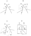
- the cut surface shown in FIG. 20 is set by the following setting method.
- a As shown in FIG. 21A, one bronchial branch T1 where the position (point) Q1 stored (registered) as a candidate position in the storage unit 27 exists is obtained.
- the cross product is obtained from the direction vectors of the two bronchial branches T1 and T2 (for example, a vector connecting the start point and the end point in the bronchial branch, a vector connecting the point on the core 35 between the start point and the bronchial branch).
- d a vector connecting the start point and the end point in the bronchial branch, a vector connecting the point on the core 35 between the start point and the bronchial branch.
- a plane including the branch point B and having the direction vector obtained in c as a normal line is obtained.
- a tomographic image is cut out in a region R1 corresponding to the length and direction vector of the core line 35 of the bronchial branch T1 on the plane obtained in d and where the registered point Q1 exists.
- FIG. 21C shows a region R2 cut out by the same setting method as that shown in FIG. 21B in the bronchial branch T3 where the terminal point Q2 in FIG. 21A exists.
- FIG. 21D shows the cut out regions R1 and R2 are bonded together to generate a combined tomographic image.
- a cutting plane showing the bronchial branch including the stored (registered) position (point) shown in FIG. 20 is set.
- the candidate position can be easily grasped from the relationship with the bronchial branch. For this reason, it has the effect that it becomes easy to perform the process of alignment more smoothly.
- an embodiment configured by partially combining the embodiments including the above-described modifications also belongs to the present invention.
Abstract
内視鏡システムは、予め取得した被検体における3次元画像情報を記憶する画像記憶部と、3次元画像情報に対して所定の視点位置から内視鏡的に描画した仮想内視鏡画像を生成する仮想内視鏡画像生成部と、内視鏡内に設けられ、所定の管腔臓器内を撮像する撮像部と、所定の管腔臓器内における内視鏡挿入部の先端の位置を検出する位置検出部と、位置検出部による内視鏡挿入部の先端の位置情報に基づいて3次元画像情報を所定方向に切り出した2次元断層画像上に、仮想内視鏡画像と撮像部により生成される内視鏡画像との画像比較を行う際の候補となる候補位置情報及び対応する仮想内視鏡画像を候補情報として提示する候補情報提示部と、を備える。
Description
本発明は被検体内を撮像手段で撮像する内視鏡システムに関する。
近年、体腔内等に挿入可能な挿入部を有する内視鏡は医療分野などにおいて広く用いられるようになっている。
一方、体腔内における気管支のように複雑に分岐した管腔臓器内に挿入して管腔臓器の末端側の目標部位(の患部組織)を検査、又は処置具による生検や処置を行うような場合においては、挿入した際に得られる内視鏡画像のみでは、目標部位付近まで挿入部先端を導入することが困難な場合がある。
このため、目標部位付近まで内視鏡の挿入部先端を導入する作業を支援するための表示等を行うシステム又は装置が提案されている。
例えば、第1の従来例としての日本国特開2002-200030号公報においては、末端の気管支を造影して3次元画像を取得することが困難となる状況であったため、気管支の3次元画像データの座標系と、挿入部先端の位置との位置合わせした後、挿入部先端の位置を順次記憶し、挿入部先端の位置の軌跡を基に、気管支の3次元画像データ上に軌跡画像を合成するマップ画像合成手段を備えた装置が開示されている。
また、第2の従来例としての日本国特開2004-89483号公報においては、目標とする患部位置に至る気管支の経路の径が予め分からないため、最適な径の気管支内視鏡を選択するにあたり、気管支の3次元画像において挿入ルートを設定し、設定した挿入ルートの所定の位置における気管支の内径を算出し、算出した気管支の内径と気管支内視鏡の挿入径から挿入限界位置を算出する装置が開示されている。
また、第3の従来例としての日本国特開2009-56238号公報においては、内視鏡により得られる観察画像としての内視鏡画像と、気管支の3次元領域の画像データに基づいて生成される仮想内視鏡画像との画像マッチングの精度を向上するために、仮想内視鏡画像や仮想内視鏡模式図画像等を内視鏡画像に重畳して表示する画像合成手段と、画像の向きを一致させる画像補正手段とが開示されている。
また、第3の従来例としての日本国特開2009-56238号公報においては、内視鏡により得られる観察画像としての内視鏡画像と、気管支の3次元領域の画像データに基づいて生成される仮想内視鏡画像との画像マッチングの精度を向上するために、仮想内視鏡画像や仮想内視鏡模式図画像等を内視鏡画像に重畳して表示する画像合成手段と、画像の向きを一致させる画像補正手段とが開示されている。
しかしながら、上述した第1の従来例から第3の従来例に開示された内容では、内視鏡の撮像手段により取得された内視鏡画像と、気管支の3次元画像データに基づいて生成される仮想内視鏡画像との画像比較により、内視鏡挿入部の先端の位置推定を行うことが困難であった。
より具体的に説明すると、内視鏡挿入部の先端の3次元位置は、仮想内視鏡画像を生成する際に用いられるCT座標系と位置合わせした後、CT座標系又はCT座標系に対応づけた座標系により管理される。しかし、内視鏡挿入部を気管支等の管腔臓器内に挿入する操作を行っている最中において、外乱等によって内視鏡挿入部の先端の3次元位置がCT座標系による3次元位置からずれてしまう場合がしばしば発生する。このような場合には、内視鏡挿入部の先端を、気管支におけるカリーナ等の既知の基準位置に設定して再度の位置合わせ(再位置合わせ)を行うことが必要になる。
より具体的に説明すると、内視鏡挿入部の先端の3次元位置は、仮想内視鏡画像を生成する際に用いられるCT座標系と位置合わせした後、CT座標系又はCT座標系に対応づけた座標系により管理される。しかし、内視鏡挿入部を気管支等の管腔臓器内に挿入する操作を行っている最中において、外乱等によって内視鏡挿入部の先端の3次元位置がCT座標系による3次元位置からずれてしまう場合がしばしば発生する。このような場合には、内視鏡挿入部の先端を、気管支におけるカリーナ等の既知の基準位置に設定して再度の位置合わせ(再位置合わせ)を行うことが必要になる。
このように位置合わせを行う場合には、内視鏡挿入部の先端をカリーナ等の基準位置に戻すことが必要となってしまうため、カリーナよりも深部側に挿入した操作が無駄になってしまう。このため、内視鏡挿入部の先端を挿入した位置かその位置付近において位置合わせを行うための候補情報を提示すると、挿入の操作の無駄が少なく、円滑な挿入の操作を続行し易くなる。
このためには、挿入の操作の最中等において、前もって再度の位置合わせの提示を行うのに適した候補情報を取得しておき、提示の指示がされた際には少なくとも指示がされた位置に到達するまでに取得した位置の候補情報としての候補位置情報と、当該候補位置情報に対応する仮想内視鏡画像とを気管支の3次元又は2次元断層画像上に候補情報として提示することが望まれる。
しかしながら、上記従来例は、このような提示の内容を開示していない。
本発明は上述した点に鑑みてなされたもので、内視鏡画像と仮想内視鏡画像とをそれぞれ生成した両位置のずれが発生したような場合においての再度の位置合わせに適した候補情報を提示することができる内視鏡システムを提供することを目的とする。
本発明の一態様の内視鏡システムは、予め取得した被検体における3次元画像情報を記憶する画像記憶部と、前記3次元画像情報に対して所定の視点位置から内視鏡的に描画した仮想内視鏡画像を生成する仮想内視鏡画像生成部と、内視鏡内に設けられ、前記所定の管腔臓器内を撮像する撮像部と、前記被検体の所定の管腔臓器内における内視鏡挿入部の先端の位置を検出する位置検出部と、前記位置検出部による前記内視鏡挿入部の先端の位置情報に基づいて前記3次元画像情報を所定方向に切り出した2次元断層画像上に、前記仮想内視鏡画像と前記撮像部の撮像により生成される内視鏡画像との画像比較を行う際の候補となる候補位置情報及び当該候補位置情報に対応する前記仮想内視鏡画像を候補情報として提示する候補情報提示部と、を備える。
以下、図面を参照して本発明の実施形態を説明する。
(第1の実施形態)
図1に示すように本発明の第1の実施形態の内視鏡システム1は、検査対象となる被検体としての患者における所定の管腔臓器としての気管支2(図2A)内に挿入される内視鏡3を備えた内視鏡装置4と、この内視鏡装置4と共に使用され、内視鏡3の挿入支援を行うための挿入支援装置5と、から主に構成される。
内視鏡装置4は、内視鏡3と、この内視鏡3に照明光を供給する光源装置6と、内視鏡3に搭載された撮像手段を構成する撮像素子7に対する信号処理を行う信号処理装置としてのカメラコントロールユニット(CCUと略記)8と、CCU8により生成された内視鏡画像を表示するモニタ9と、を有する。
(第1の実施形態)
図1に示すように本発明の第1の実施形態の内視鏡システム1は、検査対象となる被検体としての患者における所定の管腔臓器としての気管支2(図2A)内に挿入される内視鏡3を備えた内視鏡装置4と、この内視鏡装置4と共に使用され、内視鏡3の挿入支援を行うための挿入支援装置5と、から主に構成される。
内視鏡装置4は、内視鏡3と、この内視鏡3に照明光を供給する光源装置6と、内視鏡3に搭載された撮像手段を構成する撮像素子7に対する信号処理を行う信号処理装置としてのカメラコントロールユニット(CCUと略記)8と、CCU8により生成された内視鏡画像を表示するモニタ9と、を有する。
内視鏡3は、可撓性を有する細長の挿入部(又は内視鏡挿入部)11と、この挿入部11の後端に設けられた操作部12とを有し、挿入部11の先端部13には照明窓と観察窓とが設けられる。挿入部11,操作部12内には照明光を伝達するライトガイド14が挿通され、このライトガイド14の入射端は光源装置6に接続され、光源装置6内の図示しない光源ランプ又はLEDにより発生した照明光が入射端に入射される。このライトガイド14により伝達された照明光は、照明窓に取り付けられた出射端(先端面)から前方に出射される。
また、観察窓には、被写体を結像する対物光学系を形成する対物レンズ15が取り付けられ、その結像位置にCCD等の撮像素子7が配置され、対物レンズ15と撮像素子7とにより、挿入部11が挿入される所定の管腔臓器としての気管支2内を撮像する撮像手段(又は撮像部)としての撮像装置16が形成される。
また、観察窓には、被写体を結像する対物光学系を形成する対物レンズ15が取り付けられ、その結像位置にCCD等の撮像素子7が配置され、対物レンズ15と撮像素子7とにより、挿入部11が挿入される所定の管腔臓器としての気管支2内を撮像する撮像手段(又は撮像部)としての撮像装置16が形成される。
撮像素子7は、挿入部11,操作部12内を挿通された信号線を介してCCU8に接続される。CCU8は、その内部の図示しない画像信号生成回路により撮像素子7の撮像面に結像された光学像に対応する撮像画像の画像信号を生成し、この画像信号をモニタ9に出力する。モニタ9は、画像信号の画像(動画像)を、内視鏡画像(撮像画像とも言う)として表示する。
なお、内視鏡3の挿入部11には、先端部13の後端に湾曲自在の湾曲部19が設けてあり、術者は操作部12に設けた湾曲操作ノブ20を回転する操作を行うことにより、湾曲部19を上下、左右の任意の方向に湾曲することができる。
上記挿入支援装置5は、内視鏡3による検査が行われる患者に対して、公知のCT(Computed Tomography)で生成された患者の3次元画像情報としてのCTデータを、DVD、ブルーレイディスク、フラッシュメモリ等の可搬型の記憶媒体を介して取り込むCTデータ取込部21と、このCTデータ取込部21によって取り込まれたCTデータを記憶するCT画像データ記憶部22とを有する。
なお、内視鏡3の挿入部11には、先端部13の後端に湾曲自在の湾曲部19が設けてあり、術者は操作部12に設けた湾曲操作ノブ20を回転する操作を行うことにより、湾曲部19を上下、左右の任意の方向に湾曲することができる。
上記挿入支援装置5は、内視鏡3による検査が行われる患者に対して、公知のCT(Computed Tomography)で生成された患者の3次元画像情報としてのCTデータを、DVD、ブルーレイディスク、フラッシュメモリ等の可搬型の記憶媒体を介して取り込むCTデータ取込部21と、このCTデータ取込部21によって取り込まれたCTデータを記憶するCT画像データ記憶部22とを有する。
なお、CT画像データ記憶部22は、CTで生成された(被検体としての患者の3次元画像情報としての)CTデータを通信回線、インタネット等を経由して記憶しても良い。このCT画像データ記憶部22は、ハードディスク装置や、フラッシュメモリ、DVD等により構成することができる。
また、画像記憶手段を構成するCT画像データ記憶部22は、CTデータより画像データを分離したCT画像データと、CTデータより位置情報を分離した該CT画像データに対応する第1の座標系を用いた3次元の位置データとを対応付けた対応付け画像情報として記憶する対応付け画像情報記憶部22aを有する。
また、挿入支援装置5は、CT画像データ記憶部22のCT画像データから所定の管腔臓器としての気管支2の3次元画像データを抽出する管腔臓器抽出手段としての管腔臓器抽出回路、中央演算処理装置(CPUと略記)等からなる気管支抽出部23を有する。
また、画像記憶手段を構成するCT画像データ記憶部22は、CTデータより画像データを分離したCT画像データと、CTデータより位置情報を分離した該CT画像データに対応する第1の座標系を用いた3次元の位置データとを対応付けた対応付け画像情報として記憶する対応付け画像情報記憶部22aを有する。
また、挿入支援装置5は、CT画像データ記憶部22のCT画像データから所定の管腔臓器としての気管支2の3次元画像データを抽出する管腔臓器抽出手段としての管腔臓器抽出回路、中央演算処理装置(CPUと略記)等からなる気管支抽出部23を有する。
この気管支抽出部23は、抽出した気管支2の3次元データ(より具体的には3次元のボリュームデータ)から、気管支2の中空形状を表す3次元形状の情報(形状データ)と、3次元形状の画像情報(画像データ)を生成する。つまり、気管支抽出部23は、抽出した気管支2の3次元データから中空の3次元形状の気管支形状の画像としての気管支形状画像を生成する気管支形状画像生成手段としての気管支形状画像生成部23aを有する。
また、この気管支抽出部23は、気管支2の3次元データを抽出する際、3次元データに対応する第1の座標系(又はCT座標系)での3次元の位置データと対応付けて抽出する。そして、この気管支抽出部23は、気管支2の3次元形状のデータ(つまり気管支形状データ)と3次元の位置データとを対応付けした対応付け情報を記憶するメモリなどからなる対応付け情報記憶部23bを有する。
また、この気管支抽出部23は、気管支2の3次元データを抽出する際、3次元データに対応する第1の座標系(又はCT座標系)での3次元の位置データと対応付けて抽出する。そして、この気管支抽出部23は、気管支2の3次元形状のデータ(つまり気管支形状データ)と3次元の位置データとを対応付けした対応付け情報を記憶するメモリなどからなる対応付け情報記憶部23bを有する。
また、挿入支援装置5は、内視鏡3における挿入部11の先端部13に設けた撮像装置16の撮像により生成される内視鏡画像に対応する仮想的な内視鏡画像としての仮想内視鏡画像(VBS画像と言う)を生成する仮想内視鏡画像生成手段としてのVBS画像生成部24を有する。
VBS画像生成部24には、内視鏡3の撮像装置16に関する結像系の特性情報(対物レンズ15の焦点距離、撮像素子7の画素数、画素サイズ等)が、例えば入力装置31から入力される。
VBS画像生成部24は、実際に気管支2内に挿入された内視鏡3の撮像装置16の位置(挿入部11の先端の位置とも言える)の情報と、撮像装置16による気管支2内の被写体を結像する特性情報と、前記気管支形状データに基づいて、前記位置を視点位置として気管支2内を内視鏡的に撮像した内視鏡画像を仮想的に描画するVBS画像を生成する画像生成回路、CPU等により構成される。
VBS画像生成部24には、内視鏡3の撮像装置16に関する結像系の特性情報(対物レンズ15の焦点距離、撮像素子7の画素数、画素サイズ等)が、例えば入力装置31から入力される。
VBS画像生成部24は、実際に気管支2内に挿入された内視鏡3の撮像装置16の位置(挿入部11の先端の位置とも言える)の情報と、撮像装置16による気管支2内の被写体を結像する特性情報と、前記気管支形状データに基づいて、前記位置を視点位置として気管支2内を内視鏡的に撮像した内視鏡画像を仮想的に描画するVBS画像を生成する画像生成回路、CPU等により構成される。
また、挿入支援装置5は、CCU8から入力される内視鏡画像と、VBS画像生成部24のVBS画像との位置合わせを画像マッチングで行うCPU、画像処理回路等により構成される画像処理部25と、画像処理部25等の制御を行う制御手段としてのCPU等により構成される制御部26と、制御部26の制御下で挿入支援するための提示用候補情報等を記憶する記憶手段としてのメモリ等により構成される記憶部27とを有する。
また、挿入支援装置5は、CT画像データ記憶部22に記憶されたCT画像データに基づき多断面再構築画像としてのCT断層画像(MPR画像という)を生成するMPR画像生成部28と、MPR画像生成部28が生成したMPR画像を有する挿入経路の設定画面としての経路設定画面を生成し、内視鏡3の気管支2内の目標部位側へ挿入する際の経路を設定するマウス等のポインティングデバイス等の経路設定部29とを有する。
また、挿入支援装置5は、CT画像データ記憶部22に記憶されたCT画像データに基づき多断面再構築画像としてのCT断層画像(MPR画像という)を生成するMPR画像生成部28と、MPR画像生成部28が生成したMPR画像を有する挿入経路の設定画面としての経路設定画面を生成し、内視鏡3の気管支2内の目標部位側へ挿入する際の経路を設定するマウス等のポインティングデバイス等の経路設定部29とを有する。
そして、例えばCT画像データから図2A又は図10A等に示すように目標部位36を指定した場合、経路設定部29はCT画像データと気管支形状画像2aとから気管支2における(挿入部11の)挿入開始位置から目標部位36近傍となる目標位置までの経路データを生成する経路データ生成回路等の経路データ生成部29aの機能を有する。例えば、図10A等においては、Rにより目標部位36近傍となる目標位置までの経路を示している。
また、内視鏡システム1は、経路設定部29に対して設定情報を入力するキーボードやポインティングデバイス等からなる入力装置31を有する。また、術者は、この入力装置31から画像処理部25に対して、画像処理を行う際のパラメータや、データを入力したり、制御部26に対して制御動作を選択、指示することができる。
また、内視鏡システム1は、経路設定部29に対して設定情報を入力するキーボードやポインティングデバイス等からなる入力装置31を有する。また、術者は、この入力装置31から画像処理部25に対して、画像処理を行う際のパラメータや、データを入力したり、制御部26に対して制御動作を選択、指示することができる。
また、術者が経路設定を行った場合、経路設定部29は設定された経路の情報をVBS画像生成部24、MPR画像生成部28、制御部26に送る。VBS画像生成部24及びMPR画像生成部28は、それぞれ経路に沿ったVBS画像、MPR画像を生成し、制御部26は経路に沿って各部の動作の制御を行う。
上記画像処理部25には、CCU8により生成された内視鏡画像と、VBS画像生成部24により生成されたVBS画像とが入力される。また、気管支形状画像生成部23aにより生成された気管支形状画像も、画像処理部25に入力される。
本実施形態においては、撮像装置16が配置された挿入部11の先端部13に、挿入部11の先端の位置を検出するセンサを搭載していないため、画像処理部25による位置合わせ処理部25aにおける画像マッチングによって挿入部11の先端の3次元位置を推定(又は算出)する。
上記画像処理部25には、CCU8により生成された内視鏡画像と、VBS画像生成部24により生成されたVBS画像とが入力される。また、気管支形状画像生成部23aにより生成された気管支形状画像も、画像処理部25に入力される。
本実施形態においては、撮像装置16が配置された挿入部11の先端部13に、挿入部11の先端の位置を検出するセンサを搭載していないため、画像処理部25による位置合わせ処理部25aにおける画像マッチングによって挿入部11の先端の3次元位置を推定(又は算出)する。
あらかじめ、気管支2の入口やカリーナK(図2A参照)等、気管支形状画像2aからCT座標系により特定できる3次元位置(既知となる位置)又はその近傍位置を動画マッチングの開始位置として設定しておくと、その位置情報を基にVBS画像生成部はVBS画像を生成する。
そして、術者は内視鏡画像がVBS画像と同じように見えるように挿入部11の先端を挿入する。このような位置合わせを行うことにより、画像処理部25の位置合わせ処理部25aは、内視鏡画像とVBS画像とが設定された条件(所定の精度を確保できる誤差以内)で一致するように画像マッチングを開始する。このような処理を行うことにより、位置合わせ処理部25aは、挿入部11の先端の位置を推定により検出又は算出する位置推定部25bの機能を有する。
後述する図5に示す変形例のように先端部13に位置検出の位置センサ41を設け、該位置センサ41を用いて挿入部11の先端の3次元位置を検出(推定)する位置推定部42bを構成しても良い。なお、本明細書においては、挿入部11の先端は、内視鏡3の先端と同じ意味で用いる。
また、画像処理部25は、制御部26における表示を制御する表示制御部26a等の制御の下で、モニタ32に表示する画像を生成する。
表示制御部26aの制御下で、画像処理部25は、通常は、気管支形状画像生成部23aにより生成された気管支形状画像2aの画像信号(映像信号)をモニタ32に出力し、モニタ32には図2Aに示すように気管支形状画像2aが例えば(主要な)管腔の中心を通る方向に沿った断面で切り出した2次元断層画像として表示される。なお、2次元断層画像で表示する場合に限定されるものでなく、3次元画像で表示しても良い。3次元画像で表示する場合には、例えば平行投影法による投影図や、管腔内部が分かるように透視図で表示しても良い。
また、図2Aに示すように、モニタ32において表示される気管支形状画像2aには、気管支2の管腔の中心を通る芯線35も表示するようにしている。なお、芯線35は、例えば気管支形状画像生成部23aが生成するが、画像処理部25において芯線35を生成しても良い。
術者等のユーザは、挿入部11をその先端から気管支2内に挿入する場合、芯線35が表示されるため、その表示を参考にすることによって、挿入部11の挿入の操作が行い易くなる。また、芯線35に沿って挿入する操作を行うことにより、画像マッチングによる挿入部11の先端の位置の推定を短時間に行うことができる。
画像処理部25は、気管支2の深部側(末端側)に挿入する操作において、内視鏡画像とVBS画像との両画像のマッチング(画像マッチング)を利用して、CT座標系のもとで挿入部11の先端の移動した位置又は移動距離を推定する処理を行う。
つまり、ある位置において両画像がマッチングしている場合、挿入部11の先端を芯線35に沿って(挿入のために)移動する操作に伴って、撮像装置16が移動するため、内視鏡画像が変化する。
画像処理部25は、気管支2の深部側(末端側)に挿入する操作において、内視鏡画像とVBS画像との両画像のマッチング(画像マッチング)を利用して、CT座標系のもとで挿入部11の先端の移動した位置又は移動距離を推定する処理を行う。
つまり、ある位置において両画像がマッチングしている場合、挿入部11の先端を芯線35に沿って(挿入のために)移動する操作に伴って、撮像装置16が移動するため、内視鏡画像が変化する。
この場合、位置合わせ処理部25aは、芯線35に沿った経路上で移動した場合の(VBS画像生成部24から出力される)VBS画像を用いて前記内視鏡画像と最も良くマッチングするVBS画像を画像処理により選出し、選出したVBS画像に対応する3次元位置を挿入部11の先端の位置として算出(推定)する。従って、移動した移動距離も2つの位置の差分量から算出(推定)することができる。
なお、挿入部11の先端は、芯線35上から外れた位置において移動される場合もあるため、芯線35から適宜の距離だけ偏心した位置においてのVBS画像をVBS画像生成部24が生成し、生成したVBS画像を位置合わせ処理部25aに出力するようにしても良い。このようにすると、画像マッチングによる位置推定の範囲を拡大できる。上記制御部26は、位置合わせ処理部25aにより算出した挿入部11の先端の位置により経路データ生成部29aによって、(内視鏡3の挿入部11の挿入前に)生成された経路データを補正するようにしても良い。
なお、挿入部11の先端は、芯線35上から外れた位置において移動される場合もあるため、芯線35から適宜の距離だけ偏心した位置においてのVBS画像をVBS画像生成部24が生成し、生成したVBS画像を位置合わせ処理部25aに出力するようにしても良い。このようにすると、画像マッチングによる位置推定の範囲を拡大できる。上記制御部26は、位置合わせ処理部25aにより算出した挿入部11の先端の位置により経路データ生成部29aによって、(内視鏡3の挿入部11の挿入前に)生成された経路データを補正するようにしても良い。
また、制御部26は、画像処理部25により推定された挿入部11の先端が所定の条件を満たすか否かの判定を行う比較回路等により構成される条件判定部26cの機能を有し、所定の条件を満たす判定結果の場合に、該当する挿入部11の先端の位置を記憶部27に記憶する。この場合、挿入部11の先端の位置と共に、該先端の位置に対応するVBS画像を記憶部27に、提示が必要な場合に提示する(提示用の)候補情報として記憶する。
換言すると、記憶部27は、所定の条件を満たす判定結果の場合に、その判定結果が得られた場合に推定(算出)された挿入部11の先端の位置を、後で提示する場合の候補位置情報として記憶し、またこの候補位置情報と、該候補位置情報に対応するVBS画像とを提示用の候補情報として記憶する記憶手段としての候補情報記憶部27aの機能を有する。この場合には、提示用の候補情報は、候補位置の情報(候補位置情報)と該候補位置の情報に対応するVBS画像とからなるが、候補位置の情報に対応する(換言すると候補位置において生成される)VBS画像も候補VBS画像としても良い。
換言すると、記憶部27は、所定の条件を満たす判定結果の場合に、その判定結果が得られた場合に推定(算出)された挿入部11の先端の位置を、後で提示する場合の候補位置情報として記憶し、またこの候補位置情報と、該候補位置情報に対応するVBS画像とを提示用の候補情報として記憶する記憶手段としての候補情報記憶部27aの機能を有する。この場合には、提示用の候補情報は、候補位置の情報(候補位置情報)と該候補位置の情報に対応するVBS画像とからなるが、候補位置の情報に対応する(換言すると候補位置において生成される)VBS画像も候補VBS画像としても良い。
なお、候補情報記憶部27aに記憶する(提示用の)候補情報として、前記候補位置の情報に対応するVBS画像と共に、該候補位置の情報に対応する(換言すると候補位置において生成される)内視鏡画像も記憶するようにしても良い。この場合における内視鏡画像も、上記候補VBS画像の場合と同様に候補内視鏡画像と呼ぶようにしても良い。
また、画像処理部25は、表示制御部26aの候補情報提示制御部26bにより候補情報提示の制御を受けて、モニタ32に候補情報として表示するための候補情報を生成する候補情報生成部25cの機能を有する。また、画像処理部25は、内視鏡画像とVBS画像との画像マッチングを行う際に、内視鏡画像やVBS画像を一時的に記憶したり、画像処理のワークエリアとして用いる画像メモリ25dを有する。なお、画像処理部25の外部に画像メモリ25dを設けるようにしても良い。
また、画像処理部25は、表示制御部26aの候補情報提示制御部26bにより候補情報提示の制御を受けて、モニタ32に候補情報として表示するための候補情報を生成する候補情報生成部25cの機能を有する。また、画像処理部25は、内視鏡画像とVBS画像との画像マッチングを行う際に、内視鏡画像やVBS画像を一時的に記憶したり、画像処理のワークエリアとして用いる画像メモリ25dを有する。なお、画像処理部25の外部に画像メモリ25dを設けるようにしても良い。
上記条件判定部26cは、所定の条件として、気管支2における分岐に関する特徴的な領域としての特徴領域内に挿入部11の先端が位置しているか否かの判定を行う特徴領域判定部26dの機能を有する。そして、後述するように特徴領域判定部26dにより挿入部11の先端が特徴領域内に位置している(又は存在している)判定結果の場合に、候補情報記憶部27aに候補情報が記憶される。
本実施形態においては、上記所定の条件として、2つの位置(又は点)間の距離に対して一定値dthが設定されている。そして、挿入部11の先端の位置と、図2B、図2Cに示すようにカリーナKのように分岐しているスパーSpiの位置や、芯線35が分岐している分岐点Biとの位置間の距離がdth1,dth2等の一定値dth以内になった場合に、上記所定の条件を満たす特徴領域内に挿入部11の先端が位置すると判定して、候補情報を記憶部27に記憶するように設定される。
本実施形態においては、上記所定の条件として、2つの位置(又は点)間の距離に対して一定値dthが設定されている。そして、挿入部11の先端の位置と、図2B、図2Cに示すようにカリーナKのように分岐しているスパーSpiの位置や、芯線35が分岐している分岐点Biとの位置間の距離がdth1,dth2等の一定値dth以内になった場合に、上記所定の条件を満たす特徴領域内に挿入部11の先端が位置すると判定して、候補情報を記憶部27に記憶するように設定される。
なお、上記特徴領域の設定や一定値dthの値は、術者が例えば入力装置31から指定することができる。このように本実施形態においては、挿入部11を気管支2内に挿入する操作の過程において、現在の挿入部11の先端の位置以前の候補情報を記憶部27に記憶しておくことにより、画像マッチングによる最初の位置合わせ後から挿入部11の移動操作により挿入部11の先端の(画像マッチングを利用した)位置推定の精度が低下して、再度の位置合わせ(つまり再位置合わせ)を行うことが必要になった場合等においては、その再位置合わせのための候補情報を提示することができるようにしている。
また、再位置合わせを行う指示を術者が入力装置31を構成するキーボード、マウス等から画像処理部25又は制御部26に指示入力しても良い。
また、再位置合わせを行う指示を術者が入力装置31を構成するキーボード、マウス等から画像処理部25又は制御部26に指示入力しても良い。
再位置合わせの指示等がされる(又はトリガ入力される)と、制御部26の表示制御部26aは、現在の挿入部11の先端位置付近における候補情報を記憶部27の候補情報記憶部27aから読み出し、画像処理部25を経てモニタ32において候補情報を提示する制御を行う。
モニタ32において候補情報を提示する制御を行う表示制御部26aは、候補情報提示の制御を行う候補情報提示制御部26bの機能を有する。なお、表示制御部26aが候補情報記憶部27aから(提示用の)候補情報を読み出し、画像処理部25を経ることなくモニタ32において候補情報として提示する制御を行うようにしても良い。モニタ32において候補情報を提示する場合、例えば2次元断層画像として図2Dに示す気管支形状画像2a上に、画像比較を行う際の候補となる候補位置の情報及び該候補位置の情報に対応するVBS画像を表示する。
モニタ32において候補情報を提示する制御を行う表示制御部26aは、候補情報提示の制御を行う候補情報提示制御部26bの機能を有する。なお、表示制御部26aが候補情報記憶部27aから(提示用の)候補情報を読み出し、画像処理部25を経ることなくモニタ32において候補情報として提示する制御を行うようにしても良い。モニタ32において候補情報を提示する場合、例えば2次元断層画像として図2Dに示す気管支形状画像2a上に、画像比較を行う際の候補となる候補位置の情報及び該候補位置の情報に対応するVBS画像を表示する。
上述したように、画像処理部25の位置合わせ処理部25aは、挿入部11の先端が移動された場合、画像マッチングを利用して挿入部11の先端を推定(算出)するが、設定された精度以内で画像マッチングすることができなくなる画像マッチングエラーが発生する場合がある。
この場合には、画像処理部25の位置合わせ処理部25aは、画像マッチングエラーの信号を発生し、モニタ32において画像マッチングエラーが発生したことを表示する。また、位置合わせ処理部25aは、画像マッチングエラーの信号を制御部26に送り、制御部26の候補情報提示制御部26bは、モニタ32において候補情報を提示する制御を行う。
このため、上記モニタ32は、術者に対して候補情報を提示する候補情報提示手段を形成する。なお、候補情報提示手段は、モニタ32と共に、(提示用の)候補情報を記憶する候補情報記憶部27aや候補情報の画像信号を出力する画像処理部25や候補情報提示制御部26bを含めるように定義しても良い。
術者は、候補情報を用いて再度の位置合わせ処理を行う。再度の位置合わせ処理を行うことにより、術者はこの再度の位置合わせ処理を行った位置付近から挿入部11の挿入操作を続行することができるようになる。
また、術者が画像マッチングの精度が悪化したと判断した場合は、再位置合わせの指示をして上記の処理をさせてもよい。なお、図1における画像処理部25の位置合わせ処理部25a、候補情報生成部25c、気管支抽出部23、VBS画像生成部24、制御部26をCPUを用いて構成しても良いし、FPGA(Field Programmable Gate Array)のようなハードウェア化された装置、専用の電子回路素子を用いて構成しても良い。
このような構成の内視鏡システム1は、予め取得した被検体における3次元画像情報を記憶する画像記憶手段としてのCT画像データ記憶部22と、前記3次元画像情報に対して所定の視点位置から内視鏡的に描画した仮想内視鏡画像を生成する仮想内視鏡画像生成手段としてのVBS画像生成部24と、内視鏡3内に設けられ、前記所定の管腔臓器内を撮像する撮像手段としての撮像装置16と、前記被検体の所定の管腔臓器内における内視鏡挿入部11の先端の位置を検出する位置検出手段としての位置推定部25bと、前記位置検出手段による前記内視鏡挿入部11の先端の位置情報に基づいて前記3次元画像情報を所定方向に切り出した2次元断層画像上に、前記仮想内視鏡画像と前記撮像手段の撮像により生成される内視鏡画像との画像比較を行う際の候補となる候補位置情報及び当該候補位置情報に対応する前記仮想内視鏡画像を候補情報として提示する候補情報提示手段としてのモニタ32と、を備えることを特徴とする。
次に本実施形態における代表的な処理を図3のフローチャートを参照して説明する。図1の内視鏡システム1における内視鏡装置4,挿入支援装置5の電源が投入され、各部が動作状態になると、図3に示す最初のステップS1において、内視鏡3の挿入部11の先端を患者の気管支2の入口の位置等、術者が内視鏡画像で位置を判断しやすい部位を少なくとも1つ基準位置に設定する。
そして、画像処理部25の位置合わせ処理部25aは、基準位置におけるVBS画像生成部24のVBS画像(の画像信号)をモニタ32に出力する。術者は、入力装置31から基準位置の1つを指定し、挿入部11の先端を指定した基準位置に挿入するとともに、画像処理部25の位置合わせ処理部25aに対して位置合わせの処理を行うように指示する。
そして、画像処理部25の位置合わせ処理部25aは、基準位置におけるVBS画像生成部24のVBS画像(の画像信号)をモニタ32に出力する。術者は、入力装置31から基準位置の1つを指定し、挿入部11の先端を指定した基準位置に挿入するとともに、画像処理部25の位置合わせ処理部25aに対して位置合わせの処理を行うように指示する。
ステップS1の位置合わせの処理を行った後、ステップS2に示すように位置合わせ処理部25aは、位置合わせ処理の結果を基に挿入部11の先端の位置を画像マッチングにより推定(算出)する。具体的には、画像マッチングの初期値として位置合わせの情報を使用して、内視鏡画像と最も良くマッチングするVBS画像を画像処理により算出する。
ステップS3において位置合わせ処理部25aは、画像マッチングにより挿入部11の先端の推定が所定条件以内(例えば推定位置が気管支内部にあるか)でできたか否か(つまり位置の推定が成功したか否か)の判定を行う。ステップS3の判定が成功の場合には、モニタ32には、画像処理部25の位置推定部25bにより推定された挿入部11の先端の位置が、気管支形状画像2a上において、推定された位置に重畳して表示されるとともに、ステップS4の処理が行われる。一方、判定が失敗の場合にはステップS6の処理を実行する。
ステップS4において位置推定部25bにより推定された挿入部11の先端の位置情報は、制御部26の特徴領域判定部26dに入力される。そして、特徴領域判定部26dは、推定された挿入部11の先端の位置が、気管支2におけるスパーSpiや分岐点Biから(dth1,dth2等の)一定値dth以内となる特徴領域内に位置するか否かの判定を行う。ステップS4において、一定値dth以内となる判定結果の場合には、ステップS5に示すように候補情報が記憶部27に記憶される。
例えば、図2Bに示すように挿入部11の先端P1がカリーナK(第1のスパーSp1)から一定値dth1(=dth)以内と判定された場合に、推定された挿入部11の先端の位置P1が候補位置Pc1となり、該候補位置Pc1(の情報)と共に、対応するVBS画像I1とが候補情報として記憶部27に記憶される。
例えば、図2Bに示すように挿入部11の先端P1がカリーナK(第1のスパーSp1)から一定値dth1(=dth)以内と判定された場合に、推定された挿入部11の先端の位置P1が候補位置Pc1となり、該候補位置Pc1(の情報)と共に、対応するVBS画像I1とが候補情報として記憶部27に記憶される。
また、カリーナKよりも深部側に挿入部11の先端が挿入され、挿入部11の先端P2が、次のスパーSp2から一定値dth1以内となった場合に、推定された挿入部11の先端の位置P2が候補位置Pc2となり、該候補位置Pc2と共に、対応するVBS画像I2が候補情報として記憶部27に記憶される。ステップS5の処理の後、ステップS8の処理に映る。
一方、ステップS4において、挿入部11の先端がスパーSpiから一定値dth1以内に達していない場合にはステップS5の候補情報を記録する処理を行うことなくステップS8の処理を実行する。なお、図2Bにおいては、スパーSpiから一定値dth1以内と判定された場合に、候補位置Pciを記憶する例を示しているが、図2Cに示すように推定された挿入部11の先端が分岐点Biから一定値dth2(=dth)以内と判定された場合に、候補位置Pci′を記憶するようにしても良い。なお、図2Cでは挿入部11の先端P1′,P2′が分岐点B1,B2から一定値dth2以内となった場合を示している。また、一定値dth1と一定値dth2は、同じ値に設定しても良いし、異なる値に設定しても良い。
一方、ステップS4において、挿入部11の先端がスパーSpiから一定値dth1以内に達していない場合にはステップS5の候補情報を記録する処理を行うことなくステップS8の処理を実行する。なお、図2Bにおいては、スパーSpiから一定値dth1以内と判定された場合に、候補位置Pciを記憶する例を示しているが、図2Cに示すように推定された挿入部11の先端が分岐点Biから一定値dth2(=dth)以内と判定された場合に、候補位置Pci′を記憶するようにしても良い。なお、図2Cでは挿入部11の先端P1′,P2′が分岐点B1,B2から一定値dth2以内となった場合を示している。また、一定値dth1と一定値dth2は、同じ値に設定しても良いし、異なる値に設定しても良い。
ステップS8において、術者が入力装置31から候補情報の提示の指示信号(トリガ)を発生させているか検出する。これは画像マッチングの推定が失敗していることを検出できない場合、例えば、内視鏡が急激に動くと画像マッチングによる推定位置が所定条件(気管支内部にあるか)を満たしているが、明らかに別の位置であるという場合、術者が位置合わせを再度行うと判断したときに指示信号を発生させる。
ステップS8のトリガがない場合には、次のステップS9において位置推定部25bは、挿入部11の先端が目標位置まで挿入されたか否かの判定(推定)を行う。
挿入部11の先端が目標位置まで挿入されていない場合には、術者は、モニタ32に表示される表示を参考にして、ステップS10に示すように挿入部11の先端を気管支2の深部側に挿入する。ステップS10の処理の後に、ステップS2に戻り、挿入部11の先端位置の推定を行うが、画像マッチングの初期値は位置合わせの情報の代わりに前回の画像マッチングによる推定位置を使用する。一方、ステップS19において目標位置まで挿入された場合には、図3の挿入の操作を終了する。
挿入部11の先端が目標位置まで挿入されていない場合には、術者は、モニタ32に表示される表示を参考にして、ステップS10に示すように挿入部11の先端を気管支2の深部側に挿入する。ステップS10の処理の後に、ステップS2に戻り、挿入部11の先端位置の推定を行うが、画像マッチングの初期値は位置合わせの情報の代わりに前回の画像マッチングによる推定位置を使用する。一方、ステップS19において目標位置まで挿入された場合には、図3の挿入の操作を終了する。
これに対して、ステップS3の位置推定が成功しないで失敗した場合、またはステップS8のトリガがある場合には、モニタ32に処理を停止した旨、例えばマッチングエラーが表示される。この場合には、ステップS6に示すように表示制御部26aが候補情報を提示する指示信号を自動的に発生する。
そして、記憶部27の候補情報記憶部27aから候補情報が読み出される。そして、ステップS7に示すようにモニタ32には候補情報が表示される。例えば、図2BにおけるスパーSp2から一定値dth1以内となった後に挿入部11の先端の位置P3においてマッチングエラーが発生した場合には、マッチングエラーが発生する前において最も後において記憶部27(の候補情報記憶部27a)に記憶された候補位置(この場合には候補位置Pc2)と該候補位置Pc2に対応するVBS画像I2とが候補情報として提示されることになる。
この場合の提示例を図2Dに示す。図2Dに示すように気管支形状画像2a上において、候補位置Pc2と共に、該候補位置Pc2に対応するVBS画像が候補情報として表示される。なお、候補情報を提示する場合、上述したようにさらに該候補位置Pc2に対応する内視鏡画像も点線で示すように表示するようにしても良い。
この場合の提示例を図2Dに示す。図2Dに示すように気管支形状画像2a上において、候補位置Pc2と共に、該候補位置Pc2に対応するVBS画像が候補情報として表示される。なお、候補情報を提示する場合、上述したようにさらに該候補位置Pc2に対応する内視鏡画像も点線で示すように表示するようにしても良い。
また、この場合、VBS画像に隣接した位置に、同じ表示倍率で比較し易いように表示するようにしても良い。
さらに、VBS画像又は内視鏡画像の一方を移動自在に表示し、ユーザがマウス等で一方の画像を他方の画像上に重畳表示(合成表示)することができるようにしても良い。このようにすると、画像マッチングの程度をユーザが確認し易くなる。また、図2Dにおいては、1つの候補情報の提示例を示しているが、後述する図10A-図10Fに示すように複数の候補情報を提示するようにしても良い。
候補情報が表示された場合、ステップS1に戻り、術者は、モニタ32に表示された候補情報を参考にして、再度の位置合わせの処理を行う。
さらに、VBS画像又は内視鏡画像の一方を移動自在に表示し、ユーザがマウス等で一方の画像を他方の画像上に重畳表示(合成表示)することができるようにしても良い。このようにすると、画像マッチングの程度をユーザが確認し易くなる。また、図2Dにおいては、1つの候補情報の提示例を示しているが、後述する図10A-図10Fに示すように複数の候補情報を提示するようにしても良い。
候補情報が表示された場合、ステップS1に戻り、術者は、モニタ32に表示された候補情報を参考にして、再度の位置合わせの処理を行う。
このように動作する本実施形態によれば、術者が挿入部11を挿入する操作を行った場合の最中において、提示用の候補情報を記憶部27に記憶し、挿入部11の先端の位置の推定が失敗したような場合に、位置合わせに適した提示用の候補情報を候補情報として提示することができるようにしているので、挿入の操作を円滑に行うことができる。
また、本実施形態においては、画像マッチングの画像処理を利用して挿入部11の先端の位置推定を行うようにしているため、画像処理のアルゴリズムにより最初の位置合わせの状態から誤差が次第に大きくなり易くなる。このような場合にも、再度の画像マッチングによる再度の位置合わせにより、誤差を十分に小さくして、再度の位置合わせした位置付近からより深部側への挿入の操作を行うことが可能になる。
上述の説明における条件を以下のように変更しても良い。
また、本実施形態においては、画像マッチングの画像処理を利用して挿入部11の先端の位置推定を行うようにしているため、画像処理のアルゴリズムにより最初の位置合わせの状態から誤差が次第に大きくなり易くなる。このような場合にも、再度の画像マッチングによる再度の位置合わせにより、誤差を十分に小さくして、再度の位置合わせした位置付近からより深部側への挿入の操作を行うことが可能になる。
上述の説明における条件を以下のように変更しても良い。
(a)推定された挿入部11の先端の位置がスパーSpi又は分岐点Biからそれぞれ一定値dth1又はdth2以内の1つの条件を満たす場合に記憶部27に(提示用の)候補情報を記憶する例で説明したが、この条件に限らず、
(b)推定された挿入部11の先端の位置がスパーSpi及び分岐点Biからそれぞれ一定値dth1,dth2以内となった2つの条件を満たす場合に候補情報を記憶するようにしても良い。
(c)また、(a)又は(b)において、さらに推定された挿入部11の先端の位置と芯線35との距離が一定値dth3以内の場合に候補情報を記憶するようにしても良い。
(d)また、(a),(b),(c)のいずれかにおいて、内視鏡画像中に分岐の画像が見えた場合に候補情報を記憶するようにしても良い。
(e)また、(a),(b),(c),(d)のいずれかにおいて、一定値dth1-dth3は同じ値に設定しても良いし、スパーSpi又は分岐点Biでの気管支径に応じた値、又は気管支が分岐する分岐部位、又はカリーナからの分岐まで距離に応じて設定しても良い。
(f)また、図2B,図2Cの例では2点間の直線距離が一定値以内か否かにより記憶する条件とした場合で示しているが、図4に示すように挿入部11の先端の位置に最も近い芯線35上の点Pと、分岐点Biまでの芯線35上での道のり(芯線35に沿って計測した距離)dwが一定値dwth以内か否かにより報候補情報を記憶する条件としても良い。
このようにすると、屈曲した管腔部分内に挿入する場合においても適切に候補情報を記憶、及び提示が可能になる。
図5Aは第1の実施形態における変形例の内視鏡システム1Bの構成を示す。図5Aに示す内視鏡システム1Bは、図1の内視鏡システム1において、さらに挿入部11の先端部13内における撮像装置16の近傍の位置に、撮像装置16又は挿入部11の先端の位置を検出するための位置センサ41が設けてある。
また、内視鏡3及び被検体の外部となり、挿入支援装置5内の所定の位置には、この位置センサ41の3次元位置(単に位置とも記す)を計測(検出)する処理を行う計測処理装置又は計測処理部42が設けてある。位置センサ41による検出信号は、計測処理部42に入力される。
図5Aは第1の実施形態における変形例の内視鏡システム1Bの構成を示す。図5Aに示す内視鏡システム1Bは、図1の内視鏡システム1において、さらに挿入部11の先端部13内における撮像装置16の近傍の位置に、撮像装置16又は挿入部11の先端の位置を検出するための位置センサ41が設けてある。
また、内視鏡3及び被検体の外部となり、挿入支援装置5内の所定の位置には、この位置センサ41の3次元位置(単に位置とも記す)を計測(検出)する処理を行う計測処理装置又は計測処理部42が設けてある。位置センサ41による検出信号は、計測処理部42に入力される。
この計測処理部42は、位置センサ41を用いて所定の管腔臓器としての気管支2内に挿入される撮像手段を構成する撮像装置16の3次元位置、又は挿入部11の先端の3次元位置を検出又は推定する位置検出手段としての位置推定部42bの機能を有する。なお、本変形例の図5Aにおいては、図1における画像処理部25内の位置推定部25bを有しない。
位置検出(位置推定)の手段又は方法としては、例えば磁気を利用したものを利用できる。計測処理部42に接続された複数のアンテナ42aから発せられる交流磁場をコイルで構成された位置センサ41が検知し、この位置センサ41で検知した信号における、その信号の振幅及び位相を(振幅検出回路及び位相検出回路を備えた)計測処理部42が検出することによりアンテナ42aから位置センサ41までの距離を計測する。計測処理部42は、3つ以上となる複数のアンテナ42aをそれぞれ異なる既知の位置に設けることにより、位置センサ41の3次元位置を特定することが可能になる。
位置検出(位置推定)の手段又は方法としては、例えば磁気を利用したものを利用できる。計測処理部42に接続された複数のアンテナ42aから発せられる交流磁場をコイルで構成された位置センサ41が検知し、この位置センサ41で検知した信号における、その信号の振幅及び位相を(振幅検出回路及び位相検出回路を備えた)計測処理部42が検出することによりアンテナ42aから位置センサ41までの距離を計測する。計測処理部42は、3つ以上となる複数のアンテナ42aをそれぞれ異なる既知の位置に設けることにより、位置センサ41の3次元位置を特定することが可能になる。
なお、位置センサ41を構成するコイルに交流信号を印加して、その周囲に交流磁場を発生させ、アンテナ42a側で交流磁場を検知して位置センサ41の位置を検出する構成にしても良い。一例としてコイルを用いた磁気式位置検出装置を説明したが、位置センサ41及び計測処理部42の構成は、上記説明の場合に限定されるものでない。
例えば、挿入部11の長手方向に沿って所定間隔で位置検出のための複数のコイルを配置し、複数のコイルの位置から挿入部11の形状を推定し、先端部13等の位置を検出することができるようにしても良い。計測処理部42により検出(推定)された挿入部11の先端の位置情報は、制御部26と画像処理部25とに出力される。
例えば、挿入部11の長手方向に沿って所定間隔で位置検出のための複数のコイルを配置し、複数のコイルの位置から挿入部11の形状を推定し、先端部13等の位置を検出することができるようにしても良い。計測処理部42により検出(推定)された挿入部11の先端の位置情報は、制御部26と画像処理部25とに出力される。
本変形例の場合には、気管支2の3次元形状の画像データを管理するCT座標系としての第1の座標系での位置(位置情報)と、位置センサ41のアンテナ42aを基準としたセンサ座標系としての第2の座標系での位置(位置情報)との位置合わせを行う。例えば制御部26は、両座標系の位置合わせ(レジストレーション)及びその制御を行う位置合わせ部(及び位置合わせ制御部)26eの機能を持つ。
図5Bはレジストレーションの動作の説明図を示す。例えば気管支2の入り口付近における例えば4点Q0-Q3に、術者は内視鏡3の先端部13(又は位置センサ41)を順次設定して、第1の座標系O-XYZと第2の座標系o-xyzにおいてそれぞれ位置対応付けする指示又は指示入力を入力装置31から行う。このため、入力装置31は、位置対応付けの指示を行う指示入力部又は指示入力手段を形成する。
例えば、先端部13(又は位置センサ41)を、第1の座標系O-XYZにおける原点Oの位置Q0(0,0,0),X座標上の位置Q1(1,0,0)、Y座標上の位置Q2(0,1,0)、Z座標上の位置Q3(0,0,1)、に順次設定して、術者が位置対応付けの指示を行う。この指示において、各位置において計測処理部42が順次計測した位置を(x0,y0,z0)、(x1,y1,z1)、(x2,y2,z2)、(x3,y3,z3)とすると、制御部27は位置対応付けを行い、位置対応付け情報を記憶部27に記憶するように制御する。
この場合の位置対応付け情報(具体的には、第1の座標系O-XYZにおけるQ0(0,0,0)、Q1(1,0,0)、Q2(0,1,0)、Q3(0,0,1)は、第2の座標系o-xyzにおいては(x0,y0,z0)、(x1,y1,z1)、(x2,y2,z2)、(x3,y3,z3)がそれぞれ対応する情報)を記憶部27は記憶する。
また、位置合わせ部26eは、記憶部27に記憶した位置対応付け情報を用いて両座標系の任意の位置を対応つける変換情報を決定する。位置合わせ部26eは、この変換情報を記憶部27に記憶する。
また、位置合わせ部26eは、記憶部27に記憶した位置対応付け情報を用いて両座標系の任意の位置を対応つける変換情報を決定する。位置合わせ部26eは、この変換情報を記憶部27に記憶する。
図5Bにおいては、座標位置Q0(0,0,0),Q1(1,0,0),Q2(0,1,0),Q3(0,0,1)と、それぞれ対応する座標位置(x0,y0,z0)、(x1,y1,z1)、(x2,y2,z2)、(x3,y3,z3)とを簡略化してQ0⇔(x0,y0,z0)、Q1⇔(x1,y1,z1)、Q2⇔(x2,y2,z2)、Q3⇔(x3,y3,z3)で示している。なお、図5Bに示す4点でなく、そのうちの1点を省略した3点で位置対応付けを行う(決定する)ようにしても良い。
具体的には、術者は第1の座標系で指定された位置に内視鏡3の先端部13を順次接触させることになる。このとき、第1の座標系で指定された位置を表現する方法として、VBS画像を用いる。つまり、術者はVBS画像と内視鏡画像が同じに見えるよう内視鏡を操作する。
具体的には、術者は第1の座標系で指定された位置に内視鏡3の先端部13を順次接触させることになる。このとき、第1の座標系で指定された位置を表現する方法として、VBS画像を用いる。つまり、術者はVBS画像と内視鏡画像が同じに見えるよう内視鏡を操作する。
このように位置対応付けの処理が終了した後、術者は、内視鏡2の挿入部11を気管支2内に挿入して内視鏡検査を行うことを開始する。
本変形例においては、位置推定部42bにより推定された挿入部11の先端の位置に対応するCT座標系(第1の座標系)の位置が気管支2の管腔の内側となる条件から外れる場合のように、両座標系の位置ずれが明らかとなる場合に位置推定が失敗した状態と判定する。その他の構成は、図1に第1の実施形態と同様である。
本変形例の動作は、挿入部11の先端の位置を位置センサ41を用いて推定すること、位置合わせが失敗した場合に行う位置合わせを制御部26の位置合わせ部26eが行うことに変更したことを除けば第1の実施形態の動作を示す図3と殆ど同じ処理を行う。
本変形例においては、位置推定部42bにより推定された挿入部11の先端の位置に対応するCT座標系(第1の座標系)の位置が気管支2の管腔の内側となる条件から外れる場合のように、両座標系の位置ずれが明らかとなる場合に位置推定が失敗した状態と判定する。その他の構成は、図1に第1の実施形態と同様である。
本変形例の動作は、挿入部11の先端の位置を位置センサ41を用いて推定すること、位置合わせが失敗した場合に行う位置合わせを制御部26の位置合わせ部26eが行うことに変更したことを除けば第1の実施形態の動作を示す図3と殆ど同じ処理を行う。
第1の実施形態における第2の変形例は、構成は第1の変形例と同じであるが、本変形例の場合、画像処理部25の位置合わせ処理部25aは、画像マッチングにより、位置センサ41を用いた位置合わせの精度を向上するための処理を行う。
つまり、第1の実施例においては指定された位置に内視鏡3の先端部が接触するよう操作する必要があるが、その操作は難しく、推定位置の精度が悪化する要因でもある。そこで、画像マッチングで内視鏡3の先端部13のCT座標系での位置を推定し、その位置を基に指定された位置を変更することにより、確実に内視鏡3の先端部13を指定された位置に接触させる。それにより、位置ずれの誤差を所定値以下に調整することができる。
つまり、第1の実施例においては指定された位置に内視鏡3の先端部が接触するよう操作する必要があるが、その操作は難しく、推定位置の精度が悪化する要因でもある。そこで、画像マッチングで内視鏡3の先端部13のCT座標系での位置を推定し、その位置を基に指定された位置を変更することにより、確実に内視鏡3の先端部13を指定された位置に接触させる。それにより、位置ずれの誤差を所定値以下に調整することができる。
本変形例の場合には、画像処理部25の位置合わせ処理部25aは、画像マッチングによる位置合わせを行う第2の位置合わせ部の機能を有し、また、上述したように計測処理部42は、挿入部11の先端の位置を検出(又は推定)する位置推定部42bの機能を有する。
また、位置合わせ処理部25aは、両座標系の位置合わせの状態を、画像マッチングにより監視する位置合わせ監視処理部の機能を有する。例えば、挿入部11の先端が気管支2内に挿入された場合、挿入部11の先端の移動と共に、内視鏡画像と位置推定部42bによる第2の座標系での位置が変化する。
また、第2の座標系での位置の変化に対応してCT座標系(第1の座標系)の位置情報により生成されて画像処理部25に入力されるVBS画像も変化する。画像処理部25の位置合わせ処理部25aは両画像を監視し、両画像のずれ量が予め設定された値以上にずれた場合に、位置合わせが失敗した状態(又は位置合わせが必要な状態)と判定する。
また、位置合わせ処理部25aは、両座標系の位置合わせの状態を、画像マッチングにより監視する位置合わせ監視処理部の機能を有する。例えば、挿入部11の先端が気管支2内に挿入された場合、挿入部11の先端の移動と共に、内視鏡画像と位置推定部42bによる第2の座標系での位置が変化する。
また、第2の座標系での位置の変化に対応してCT座標系(第1の座標系)の位置情報により生成されて画像処理部25に入力されるVBS画像も変化する。画像処理部25の位置合わせ処理部25aは両画像を監視し、両画像のずれ量が予め設定された値以上にずれた場合に、位置合わせが失敗した状態(又は位置合わせが必要な状態)と判定する。
また、本変形例においては、位置推定部42bにより推定された挿入部11の先端の位置に対応するCT座標系(第1の座標系)の位置が気管支2の管腔の内側となる条件から外れる場合のように、両座標系の位置ずれが明らかとなる場合も位置合わせが失敗した状態(又は位置合わせが必要な状態)と判定する。その他の構成は、図1に第1の実施形態と同様である。
本変形例の動作は、挿入部11の先端の位置を位置センサ41を用いて推定すること、位置合わせが失敗した場合に行う位置合わせを制御部26の位置合わせ部26eが行うことに変更したことを除けば第1の実施形態の動作を示す図3と殆ど同じ処理を行う。
本変形例の動作は、挿入部11の先端の位置を位置センサ41を用いて推定すること、位置合わせが失敗した場合に行う位置合わせを制御部26の位置合わせ部26eが行うことに変更したことを除けば第1の実施形態の動作を示す図3と殆ど同じ処理を行う。
第1、又は第2の変形例によれば、術者が挿入部11を挿入する操作を行った場合の最中において、提示用の候補情報を記憶部27に記憶し、挿入部11の先端の位置の推定が失敗したような場合に、位置合わせに適した提示用の候補情報を提示することができるようにしているので、挿入の操作を円滑に行うことができる。
また、第1、又は第2の変形例においては、最初の位置合わせ後に位置センサ41を用いて挿入部11の先端の位置推定を行うようにしており、位置合わせした位置からの距離が大きくなると、最初の位置合わせの状態から誤差が大きくなり易くなる。このような場合にも、位置センサ41を用いると共に、画像マッチングを用いた再度の位置合わせにより、誤差を十分に小さくして、再度の位置合わせした位置付近からより深部側への挿入の操作を円滑に行うことが可能になる。
また、第1、又は第2の変形例においては、最初の位置合わせ後に位置センサ41を用いて挿入部11の先端の位置推定を行うようにしており、位置合わせした位置からの距離が大きくなると、最初の位置合わせの状態から誤差が大きくなり易くなる。このような場合にも、位置センサ41を用いると共に、画像マッチングを用いた再度の位置合わせにより、誤差を十分に小さくして、再度の位置合わせした位置付近からより深部側への挿入の操作を円滑に行うことが可能になる。
なお、図1又は図5Aの構成において、上述した所定の条件を満たす場合には、提示用の候補情報を記憶部27の候補情報記憶部27aに記憶するが、候補情報を記憶した後には、殆ど同じ候補位置ないしは類似した候補位置での候補情報を記憶することを制限する候補情報の記憶制限手段を設けるようにしても良い。
例えば、候補情報を記憶した後には、推定された挿入部11の先端の位置が当該候補位置から、予め設定された制限距離未満での次の候補情報の記憶を禁止(抑制)し、設定された制限距離以上移動した場合に候補情報の禁止(抑制)を解除して、上述した所定の条件を満たす場合に次の候補情報を記憶する候補情報の記憶制限部を設けるようにしても良い。または、初めに特徴領域内に到達した位置、最後に特徴領域内にあった位置、分岐点Biに最も近傍である位置、先の分岐が判別しやすい位置でもよい。この選択は術者が入力装置31を構成するキーボード、マウス等から画像処理部25又は制御部26に指示入力しても良い。
例えば、候補情報を記憶した後には、推定された挿入部11の先端の位置が当該候補位置から、予め設定された制限距離未満での次の候補情報の記憶を禁止(抑制)し、設定された制限距離以上移動した場合に候補情報の禁止(抑制)を解除して、上述した所定の条件を満たす場合に次の候補情報を記憶する候補情報の記憶制限部を設けるようにしても良い。または、初めに特徴領域内に到達した位置、最後に特徴領域内にあった位置、分岐点Biに最も近傍である位置、先の分岐が判別しやすい位置でもよい。この選択は術者が入力装置31を構成するキーボード、マウス等から画像処理部25又は制御部26に指示入力しても良い。
例えば図1、図5Aにおいて制御部26内に(候補情報の)記憶制限部26fを設けた構成を点線で示している。
このようにすると、記憶部27の候補情報記憶部27aに記憶された候補情報を読み出してモニタ32に提示する場合の候補情報が多くなりすぎることを抑制でき、術者は位置合わせに適した適度の数の候補情報から位置合わせの作業を行うことができるようになる。従って、術者は、位置合わせの作業が行い易くなる効果を有する。
なお、記憶を制限する制限距離としては、気管支2の分岐点BiやスパーSpiの情報等から設定しても良い。具体的には、例えば気管支の芯線35に沿って存在する隣接する分岐点BiとBi+1間の距離等に基づいて制限距離を設定するようにしても良い。具体例として、例えば隣接する分岐点間距離の1/2を制限距離に設定しても良い。
また、記憶部27の候補情報記憶部27aに候補情報を記憶する条件を制限する代わりに、提示に適した候補情報のみを選択的に抽出(つまり制限)して提示するように提示選択情報又は提示制限情報を(候補情報に)追加して記憶するようにしても良い。このため、例えば図1,図5Aにおいて、候補情報記憶部27aがさらに提示選択情報又は提示制限情報を記憶する提示制限情報記憶部27bを含むように提示選択情報又は提示制限情報を記憶するようにしても良い。
上述した所定の条件として例えば分岐点Biから一定値dth2以内となる条件(特徴領域内に存在する条件)を最初に満たす位置Pi′とした場合、この位置Pi′を候補位置として候補情報として記憶する場合、提示制限情報として例えば(Bi,1)も追加して記憶する。ここで、(Bi,1)は(分岐点Bi、条件を満たす最初の位置の番号)を意味する。
さらに挿入部11の先端が深部側に移動された場合、適宜の時間間隔で次の位置Pi+1′とした場合、この位置Pi+1′を候補位置として候補情報として記憶する場合、提示制限情報として例えば(Bi,2)も追加して記憶する。このようにして、分岐点Biから一定値dth2以内となる条件を満たす複数の候補情報を記憶した場合において、再度の位置合わせのための候補情報の提示の指示がされた場合には、例えば分岐点Bi付近において条件を満たす最初の位置の番号1の候補情報のみを提示(表示)するように制限しても良い。なお、術者が例えば入力装置31から提示する数の条件を変更することによりモニタ32で提示する候補情報の数を変更するようにすることもできる。
このようにした場合にも、モニタ32で候補情報を提示する場合の提示用の候補情報が多くなりすぎることを抑制でき、術者は位置合わせに適した適度の数の候補情報から位置合わせの作業を行うことができるようになる。従って、術者は、位置合わせの作業が行い易くなる効果を有する。
さらに、気管支形状画像やVBS画像を生成するに当たり、CT画像データから所定の管腔臓器としての気管支2の3次元画像データを抽出するのでなく、CT画像データよりボリュームレンダリングで直接生成してもよい。この場合、図1または図5Aにおける気管支抽出部23は不要であり、VBS画像生成部24が前記2種類の画像を生成する。
(第2の実施形態)
次に本発明の第2の実施形態を説明する。本実施形態は、図1の内視鏡システム1又は図5Aの内視鏡システム1Bと同じ構成である。
本実施形態は、上述した(b)の内容に近くなるが、2点間の距離が第1の閾値を満たす条件と、第2の閾値とを満たす場合に候補情報を記憶する。本実施形態においては、推定された挿入部11の先端の位置が、例えばPiで分岐点Biから第1の閾値dt2以内となった後、さらにPi+1まで進んで分岐点Biから第2の閾値dt1以上となった条件を満たした場合に、挿入部11の先端が分岐点Biに到達したと判断して第1の閾値dt2以内となったときの候補情報を記憶する。
図6は、第2の実施形態における挿入の操作中における候補情報を記憶する動作の説明図を示す。図6に示すように例えば挿入部11の先端がスパーSpi-1よりも深部側に挿入された場合、推定された挿入部11の先端の位置Piと次の分岐点Biの位置間の距離が一定値dth2以内か否かの第1の判定が制御部26の特徴領域判定部26dにより行われる。
また、特徴領域判定部26dは、第1の判定により推定された挿入部11の先端の位置Piと分岐点Biの位置の距離が第1の閾値dt2以内となった後、さらに推定された挿入部11の先端の位置Piと分岐点Biの位置間の距離が第2の閾値dt1以上か否かの第2の判定を行う。
そして、第2の判定により推定された挿入部11の先端の位置Pjと分岐点Biの位置間の距離が第2の閾値dt1以上となった場合に第1の閾値dt2以内となったときの候補情報を記憶する。
この場合、図6に示すように第1の閾値dt1と第2の閾値dt2とをdt1>dt2に設定しておくと、図6に示すように挿入部11の先端が分岐点Bi近傍に到達した状態での候補情報を記憶することができる。
そして、第2の判定により推定された挿入部11の先端の位置Pjと分岐点Biの位置間の距離が第2の閾値dt1以上となった場合に第1の閾値dt2以内となったときの候補情報を記憶する。
この場合、図6に示すように第1の閾値dt1と第2の閾値dt2とをdt1>dt2に設定しておくと、図6に示すように挿入部11の先端が分岐点Bi近傍に到達した状態での候補情報を記憶することができる。
本実施形態によれば、第1の実施形態のように術者が挿入部11を挿入する操作を行った場合の最中において、提示用の候補情報を記憶部27に記憶し、挿入部11の先端の位置の推定が失敗したような場合に、提示用の候補情報を提示することができるようにしているので、挿入の操作を円滑に行うことができる。
更に、本実施形態によれば、挿入部11の先端が分岐点Biの近傍の位置に到達した状態を精度良く検出できる。
なお、本実施形態の具体例として、挿入部11の先端の位置と分岐点Biとの距離に関して2つの閾値を設定した場合で説明したが、挿入部11の先端の位置とスパーSpi間の距離や、挿入部11の先端に最も近い芯線35上の位置と分岐点Bi間の距離等を用いるようにしても良い。
更に、本実施形態によれば、挿入部11の先端が分岐点Biの近傍の位置に到達した状態を精度良く検出できる。
なお、本実施形態の具体例として、挿入部11の先端の位置と分岐点Biとの距離に関して2つの閾値を設定した場合で説明したが、挿入部11の先端の位置とスパーSpi間の距離や、挿入部11の先端に最も近い芯線35上の位置と分岐点Bi間の距離等を用いるようにしても良い。
(第3の実施形態)
次に本発明の第3の実施形態を説明する。本実施形態の内視鏡システムは、図1の内視鏡システム1又は図5Aの内視鏡システム1Bと同じ構成である。本実施形態においては、挿入部11の先端がある分岐点付近を通り、当該分岐点付近から枝分かれした次の気管支枝(小枝)に移動したような場合、その前に取得した挿入部11の先端の位置で候補情報を記憶する。
図7は本実施形態の場合の動作説明図を示す。例えば挿入部11の先端が位置Pkにおいて、その位置が推定された後、さらに挿入部11の先端が移動して、枝分かれした1つの気管支枝(小枝)内の位置Pk+1に達した(又は移動した)場合に、位置Pkでの候補情報を記憶する。なお、図7以降においては、挿入部11の先端の位置を小円で示す。
1つの気管支枝(小枝)内の位置Pk+1に達した(又は移動した)場合とは、図7に示すように挿入部11の先端の位置に最も近い芯線35が小枝のものであった場合に該当する。この状態を判定するために、図7に示すように例えば分岐点Biを中心にした距離として半径dtの円の領域を設定し、特徴領域判定部26dは、推定された挿入部11の先端がこの円の領域内に位置に存在する第1の状態を判定した後、この円の領域以上の外側に移動した第2の状態を判定するようにしても良い。図7の例では半径dtは、分岐点BiとスパーSpiの位置間の距離ないしはこの距離よりも若干大きい値に設定されている。
また、内視鏡画像により判定するようにしても良い。例えば上記半径dtの円内において内視鏡画像中に分岐した気管支枝の画像としての例えば2つの暗い円形画像を確認した後、挿入部11の先端の移動により1つの暗い円形画像となった場合においては、前記2つの暗い円形画像を確認した状態中において、位置合わせのエラーが発生していない状態の位置で取得した当該位置と対応するVBS画像を候補情報として記憶するようにしても良い。
また、内視鏡画像により判定するようにしても良い。例えば上記半径dtの円内において内視鏡画像中に分岐した気管支枝の画像としての例えば2つの暗い円形画像を確認した後、挿入部11の先端の移動により1つの暗い円形画像となった場合においては、前記2つの暗い円形画像を確認した状態中において、位置合わせのエラーが発生していない状態の位置で取得した当該位置と対応するVBS画像を候補情報として記憶するようにしても良い。
また、図7に示す円形に設定した領域の変形例として例えば分岐点Biからの芯線35上での距離がdtとなる境界Bt(図7において点線で示す)を設定しても良い。このように境界Btを設定した場合もほぼ同様の作用効果を有する。
また、本実施形態の変形例として挿入部11の先端が順次通過した2つの分岐点からの距離が両者とも増加した場合に、増加する直前において位置合わせのエラーが発生していない状態で取得した位置での当該位置と対応するVBS画像を候補情報として記憶するようにしても良い。
図8は本変形例の場合の動作説明図を示す。図8に示すように推定された挿入部11の位置Pkが、分岐点Bi-1と、該分岐点Bi-1の次の分岐点Biを通過して気管支のより深部(末端)側に挿入された場合、特徴領域判定部26dは、以下の条件を監視する。
また、本実施形態の変形例として挿入部11の先端が順次通過した2つの分岐点からの距離が両者とも増加した場合に、増加する直前において位置合わせのエラーが発生していない状態で取得した位置での当該位置と対応するVBS画像を候補情報として記憶するようにしても良い。
図8は本変形例の場合の動作説明図を示す。図8に示すように推定された挿入部11の位置Pkが、分岐点Bi-1と、該分岐点Bi-1の次の分岐点Biを通過して気管支のより深部(末端)側に挿入された場合、特徴領域判定部26dは、以下の条件を監視する。
特徴領域判定部26dは、分岐点Bi-1と位置Pkとの第1の距離d1と、分岐点Biと位置Pkとの第2の距離d2とが共に増加する条件を満たした場合に、この条件を満たす直前において位置合わせのエラーが発生していない状態の位置(例えばPk-1)で取得した当該位置と対応するVBS画像を候補情報として記憶する。
本変形例は、第2の実施形態とほぼ同様の効果を有する。
この他に、図9に示すように内視鏡画像における分岐の特徴量となる(気管支2が分岐した)小枝の重心間の距離dgが変化した場合に、候補情報を記憶するようにしても良い。なお、図9において上下の各内視鏡画像Ik、Ik+1は、例えば挿入部11の先端が位置Pk、Pk+1においてそれぞれ取得した場合の画像であり、画像処理部25は、2値化処理等により抽出した暗部を小枝(の部分)の画像Ia,Ibとして算出する。
本変形例は、第2の実施形態とほぼ同様の効果を有する。
この他に、図9に示すように内視鏡画像における分岐の特徴量となる(気管支2が分岐した)小枝の重心間の距離dgが変化した場合に、候補情報を記憶するようにしても良い。なお、図9において上下の各内視鏡画像Ik、Ik+1は、例えば挿入部11の先端が位置Pk、Pk+1においてそれぞれ取得した場合の画像であり、画像処理部25は、2値化処理等により抽出した暗部を小枝(の部分)の画像Ia,Ibとして算出する。
さらに画像処理部25は、各小枝の画像Ia,Ibの重心Ga,Gbを算出し、重心間の距離dgを推定する。そして、画像処理部25は、重心Ga,Gb間の距離dgが位置Pkから位置Pk+1に移動した場合に所定値以上又は所定の比率以上に変化した場合に、例えば位置Pkにおいての候補情報を記憶する。このようにした場合にも、第3の実施形態とほぼ同様の効果を有する。なお、図9における2つの小枝の画像Ia,Ibの外側の円形は、気管支2の管腔内壁を示す。
図9のように重心Ga,Gb間の距離dgが変化した場合の代わりに、小枝を楕円形とみなした場合の代表半径又は代表半径の比が変化した場合に候補情報を記憶するようにしても良い。
また、画像Ia、Ibの画素の和が変化した場合に候補情報を記憶するようにしても良い。
次に上述した実施形態においてマッチングエラーや位置合わせが失敗した場合、又はユーザが位置合わせを行うために候補情報の提示の指示がされたような場合における候補情報の提示例を説明する。図2Dにおいては、候補情報の1つの提示例を示したが、以下のように提示するようにしても良い。
図9のように重心Ga,Gb間の距離dgが変化した場合の代わりに、小枝を楕円形とみなした場合の代表半径又は代表半径の比が変化した場合に候補情報を記憶するようにしても良い。
また、画像Ia、Ibの画素の和が変化した場合に候補情報を記憶するようにしても良い。
次に上述した実施形態においてマッチングエラーや位置合わせが失敗した場合、又はユーザが位置合わせを行うために候補情報の提示の指示がされたような場合における候補情報の提示例を説明する。図2Dにおいては、候補情報の1つの提示例を示したが、以下のように提示するようにしても良い。
図10Aは、上述した実施形態において所定の条件を満たす場合において候補情報として記憶された候補位置をPc1、Pc2,Pc3で示し、また対応するVBS画像をV1,V2,V3で示している。そして、例えば術者が候補情報の提示の指示を行った場合、気管支形状画像2a上に上記候補位置Pc1、Pc2,Pc3を重畳表示し、また、対応するVBS画像V1,V2,V3も上記候補位置Pc1、Pc2,Pc3に対応付けて(例えば候補位置Pci(i=1,2,3)とVBS画像Viとを線で結ぶ等して)表示する。なお、図2Dにおいて示したように候補位置Pciに対応する内視鏡画像もVBS画像Viと比較し易い位置に同時に表示するようにしても良い。
また、図10Aに示すように目標部位36を気管支形状画像2a画像上に重畳表示すると共に、気管支形状画像2a画像上に内視鏡3の挿入部11を挿入する経路Rを重畳表示する。また、図示していない内視鏡3の先端部13の軌跡を表示してもよい。
また、図10Aに示すように目標部位36を気管支形状画像2a画像上に重畳表示すると共に、気管支形状画像2a画像上に内視鏡3の挿入部11を挿入する経路Rを重畳表示する。また、図示していない内視鏡3の先端部13の軌跡を表示してもよい。
このように候補情報を提示することによりユーザは再度の位置合わせを短時間に効率良く行い易くなり、目標部位36への挿入を円滑に行い易くなる。なお、内視鏡3の挿入部11の先端が(経路データとしての)経路Rから(例えば管腔径程度などの)所定距離遠ざかったと判定した場合にも、例えば図10Aに示すような候補情報を提示するようにしても良い。
また、図10Bに示すように記憶された候補位置Pc1、Pc2,Pc3′、Pc3の間を、移動に沿った線L12,L23′、L23で結ぶように表示するようにしても良い。図10Bの場合においては、候補位置Pc1,Pc2,Pc3′の順に候補情報を記憶した後、候補位置Pc3′から再び候補位置Pc2に戻り、候補位置Pc3′側の小枝とは異なる小枝側の候補位置Pc3に移動した場合の例を示す。上記のように移動したため、線L12,L23′、L23を表示(提示)する。なお、候補位置Pc3′に対応するVBS画像をV3′で示している。その他は、図10Aにおいて説明した内容と同様であり、同様の効果を有する。
また、図10Bに示すように記憶された候補位置Pc1、Pc2,Pc3′、Pc3の間を、移動に沿った線L12,L23′、L23で結ぶように表示するようにしても良い。図10Bの場合においては、候補位置Pc1,Pc2,Pc3′の順に候補情報を記憶した後、候補位置Pc3′から再び候補位置Pc2に戻り、候補位置Pc3′側の小枝とは異なる小枝側の候補位置Pc3に移動した場合の例を示す。上記のように移動したため、線L12,L23′、L23を表示(提示)する。なお、候補位置Pc3′に対応するVBS画像をV3′で示している。その他は、図10Aにおいて説明した内容と同様であり、同様の効果を有する。
また、図10Cは、例えば図10Aの場合においてさらに内視鏡3の挿入部11の先端が候補位置Pciで候補情報を記憶した時点から所定の時間が経過した時点において挿入部11の先端の位置を取得することによって、候補位置Pciからの動き方向Miを算出し、候補情報として、又は候補情報の付帯情報として記憶する。そして、図10Cに示すように候補情報の提示の際に図10Aで説明した候補情報の提示の際に、動き方向Miも表示(提示)する。その他は、図10Aにおいて説明した内容と同様であり、図10Aの場合と同様の効果を有すると共に、動き方向Miを参考にすることによってより位置合わせを行い易くなる。
図10Dは、例えば図10Aの場合においてさらに内視鏡3の挿入部11の先端の位置Pciで候補情報を記憶する場合、撮像装置16の(対物レンズ15に基づく)視線方向Ciも記憶する。そして、図10Dに示すように候補情報の提示の際に図10Aで説明した候補情報の提示の際に、視線方向Ciも表示(提示)する。その他は、図10Aにおいて説明した内容と同様である。視線方向Ciの提示により位置合わせを行い易くなる。
図10Dは、例えば図10Aの場合においてさらに内視鏡3の挿入部11の先端の位置Pciで候補情報を記憶する場合、撮像装置16の(対物レンズ15に基づく)視線方向Ciも記憶する。そして、図10Dに示すように候補情報の提示の際に図10Aで説明した候補情報の提示の際に、視線方向Ciも表示(提示)する。その他は、図10Aにおいて説明した内容と同様である。視線方向Ciの提示により位置合わせを行い易くなる。
図10Dにおいては、候補情報を提示する場合に視線方向Ciも提示することができる例を説明した。図10Dにおいては、2次元的に視線方向Ciを表示する場合を示した。これに対して、図10Eに示すように、例えば四角錐等を用いて視線方向Ci′を表示し、視線方向Ci′を3次元的な方向としてユーザが認識し易いように表示(提示)するようにしても良い。図10Eに示すように提示すると、ユーザは視線方向Ci′をより認識し易くなる。
図10Fは、例えば図10Aの場合においてさらに候補情報を記憶した場合に気管支2の管腔径の情報として気管支2の3次元形状より算出した内径Diの情報を記憶し、候補情報を提示する場合に、記憶した内径Diの情報も提示する例を示す。図10Fのように内径Diの情報も表示することにより、ユーザは挿入部11の先端の位置をより把握し易くなる。その他は、図10Aの場合と同様の作用効果を有する。
図10Gに示すように4つの位置に文字情報(具体的にはA,B,C,D)を付け、対応するVBS画像にも同じ文字情報で関係付けて表示しても良い。図10Gでは図10Bの場合のように、候補位置Pc1,Pc2,Pc3′の順に候補情報を記憶した後、候補位置Pc3′から再び候補位置Pc2に戻り、候補位置Pc3′側の小枝とは異なる小枝側の候補位置Pc3に移動した場合の例を示す。なお、VBS画像を気管支形状画像2aの下側に配置しても良い。
図10Gに示すように提示すると、ユーザは時系列で位置を確認することができ、挿入部11の先端の位置をより把握し易くなる。また、図示はしないがVBS画像に候補情報を記憶した順番や時刻を付加して表示してもよい。更に、位置に対する文字情報の割り当てはPc3、Pc3’、Pc2、Pc1と時系列で逆となるようにしてよいし、最後に位置推定に成功した位置から近い順にしてもよい。
上述した提示例は、気管支形状画像2a上に候補位置等の候補情報を重畳表示する例を説明したが、以下に示すように候補位置となる位置を気管支2を含む断層像画像(MPR画像)上に表示するようにしても良い。
図11は、上述した第1-第3の実施形態に適用できるモニタ32に表示する例を示す。図11の左上は患者の気管支を含む横断面のCT断層画像を示し、図11の右上は患者の正面に垂直な縦断面のCT断層画像を示し、図11の左下は患者の正面に並行な縦断面のCT断層画像を示し、図11の右下はユーザが座標を設定する場合のメニュー画面を示す。
図11は、挿入部11の先端(又は先端に設けた撮像装置16)の推定された位置(点)を断層画像上に、例えば同じ色の円その他の形状で表示する。図11では、4つの位置を、断層画像の表示色と異なる色(例えば青色)で表示する。
図11は、上述した第1-第3の実施形態に適用できるモニタ32に表示する例を示す。図11の左上は患者の気管支を含む横断面のCT断層画像を示し、図11の右上は患者の正面に垂直な縦断面のCT断層画像を示し、図11の左下は患者の正面に並行な縦断面のCT断層画像を示し、図11の右下はユーザが座標を設定する場合のメニュー画面を示す。
図11は、挿入部11の先端(又は先端に設けた撮像装置16)の推定された位置(点)を断層画像上に、例えば同じ色の円その他の形状で表示する。図11では、4つの位置を、断層画像の表示色と異なる色(例えば青色)で表示する。
なお、先端の位置を候補情報における候補位置(情報)として提示する場合、図10A-図10Fのように位置と、位置に対応するVBS画像とを線を用いて関係付けて表示しても良いし、図12に示すように4つの位置に文字情報(具体的にはA,B,C,D)を付け、対応するVBS画像にも同じ文字情報で関係付けて表示しても良い。
以下に説明する場合においては、位置を断層画像上に重畳して表示する様子を示す例であり、位置と対応するVBS画像との文字情報等で関連付けて提示する表示を省略する。
図11では、推定された位置が、切断面上に有る場合と、それ以外の場合とで同じ色、形状で示しているが、図13に示すように、切断面上に有る場合と、切断面上に無い場合とで、異なる形状(例えば前者を円、後者を四角)で表示するようにしても良いし、色を変えるようにしても良い。また、切断面上に有る場合のみを表示するようにしても良い。
以下に説明する場合においては、位置を断層画像上に重畳して表示する様子を示す例であり、位置と対応するVBS画像との文字情報等で関連付けて提示する表示を省略する。
図11では、推定された位置が、切断面上に有る場合と、それ以外の場合とで同じ色、形状で示しているが、図13に示すように、切断面上に有る場合と、切断面上に無い場合とで、異なる形状(例えば前者を円、後者を四角)で表示するようにしても良いし、色を変えるようにしても良い。また、切断面上に有る場合のみを表示するようにしても良い。
また、例えば図11のように表示する場合、更に図14において矢印で示すように移動方向の情報も表示するようにしても良い。上述したように分岐点等から一致値以内などの所定の条件を満たしたときの(挿入部11の先端の)位置で候補情報を記憶した場合、その直後の位置の情報も記憶し、候補情報を表示する場合、2点間を結ぶ矢印を図13に示すように移動方向として表示する。なお、移動方向を示すものの代わりに、挿入部11の先端に設けた撮像装置16の視線方向を表示するようにしても良い。
また、2点間を結ぶ矢印でなく、候補位置での撮像装置16の視野範囲又はVBS画像の視野範囲を図15に示すように表示しても良い。
また、図15ではMPR画像での表示であるため、視野範囲も切断面に投影した形状となっているが、図16に示すように1つの断層像上で表示する場合には視野範囲を四角錐を用いて立体的に表示しても良い。
また、2点間を結ぶ矢印でなく、候補位置での撮像装置16の視野範囲又はVBS画像の視野範囲を図15に示すように表示しても良い。
また、図15ではMPR画像での表示であるため、視野範囲も切断面に投影した形状となっているが、図16に示すように1つの断層像上で表示する場合には視野範囲を四角錐を用いて立体的に表示しても良い。
また、記憶した位置を点で表示(提示)する代わりに、領域で表示(提示)するようにしても良い。図17は、この場合の提示例を示す。図17において、斜線で示す領域は、既に記憶部27に候補位置に相当する候補領域として記憶済み(登録済み)の領域であり、これに対してクロスハッチングした領域は、未登録の領域を示す。
このように登録済みの領域と未登録の領域とを識別できるように表示すると、ユーザが望む気管支2の小枝部分において、登録が完了しているか否かが容易に分かる。そのため、ユーザに対する利便性を向上できる。
なお、表示(提示)する場合の領域としては、ユーザなどが再度の位置合わせの指示した位置から一定範囲内となる条件を満たす範囲内でも良いし、気管支2における小枝でも良いし、気管支2における抽出された部分に同時に表示しても良い。
このように登録済みの領域と未登録の領域とを識別できるように表示すると、ユーザが望む気管支2の小枝部分において、登録が完了しているか否かが容易に分かる。そのため、ユーザに対する利便性を向上できる。
なお、表示(提示)する場合の領域としては、ユーザなどが再度の位置合わせの指示した位置から一定範囲内となる条件を満たす範囲内でも良いし、気管支2における小枝でも良いし、気管支2における抽出された部分に同時に表示しても良い。
また、図11から図17における断層画像(MPR画像)が肺野のどの部分であるかをユーザが容易に把握できるよう、図18に示すように断層画像と気管支樹と組み合わせて表示するようにしても良い。
この場合、断層画像と気管支樹の位置関係は、記憶した点が断層画像上になるように設定しても良いし、その点から任意の方向にオフセット分移動しても良い。
また、図18では1つの断層画像を示す例を示しているが、図19に示すように2つ以上の断層画像と組み合わせるようにしても良い。
上述した図11-図19のMPR画像の断面としては、体に水平な体軸断面(アキシャル断面, axial 断面)と、縦切りの矢状断面(サジタル断面, sagittal 断面)と、横切りの冠状断面(コロナル断面, coronal 断面)という3つの断面のいずれかが用いられる。しかし、気管支樹の形状を考慮していないため、気管支樹の分岐の認識が容易でない場合がある。そこで、分岐を認識し易いように図20に示すように記憶(登録)した点の気管支枝を含むような切断面を設定しても良い。
図20に示す切断面は、以下の設定方法により設定される。
a.図21(A)に示すように記憶部27に候補位置として記憶(登録)された位置(点)Q1が存在する気管支枝T1を1つ求める。
b.図21(A)に示すように求めた気管支枝T1と同じ分岐点Bを共有する気管支枝T2を求める。
c.2つの気管支枝T1、T2の方向ベクトル(例えば気管支枝における開始点と終点とを結ぶベクトルや、開始点と気管支枝の中間の芯線35上の点を結ぶベクトルなど)から外積を求める。
d.分岐点Bを含み、cで求めた方向ベクトルを法線とする平面を求める。
e.図21(B)に示すようにdにおいて求めた平面上にあり、かつ登録された点Q1が存在する気管支枝T1の芯線35の長さや方向ベクトルに応じた領域R1で断層画像を切り出す。
f.上述のa-eの処理を全ての登録された点Q1等が存在する気管支枝T1等に対して行う。図21(C)は、図21(A)の末端側の点Q2が存在する気管支枝T3において、図21(B)に示した場合と同様の設定方法で切り出す領域R2を示す。
g.図21(D)に示すように切り出した領域R1,R2を貼り合わせて、貼り合わせ断層画像を生成する。このようにして、図20に示した記憶(登録)された位置(点)を含む気管支枝を示す切断面が設定される。図20のように表示すると、候補位置を気管支枝との関連性から把握し易くなる。このため、位置合わせの処理をより円滑に行い易くなる効果を有する。
なお、上述した変形例を含む実施形態を部分的に組み合わせて構成される実施形態等も本発明に属する。
g.図21(D)に示すように切り出した領域R1,R2を貼り合わせて、貼り合わせ断層画像を生成する。このようにして、図20に示した記憶(登録)された位置(点)を含む気管支枝を示す切断面が設定される。図20のように表示すると、候補位置を気管支枝との関連性から把握し易くなる。このため、位置合わせの処理をより円滑に行い易くなる効果を有する。
なお、上述した変形例を含む実施形態を部分的に組み合わせて構成される実施形態等も本発明に属する。
本出願は、2013年3月12日に日本国に出願された特願2013-49290号を優先権主張の基礎として出願するものであり、上記の開示内容は、本願明細書、請求の範囲に引用されるものとする。
Claims (13)
- 予め取得した被検体における3次元画像情報を記憶する画像記憶部と、
前記3次元画像情報に対して所定の視点位置から内視鏡的に描画した仮想内視鏡画像を生成する仮想内視鏡画像生成部と、
内視鏡内に設けられ、前記所定の管腔臓器内を撮像する撮像部と、
前記被検体の所定の管腔臓器内における内視鏡挿入部の先端の位置を検出する位置検出部と、
前記位置検出部による前記内視鏡挿入部の先端の位置情報に基づいて前記3次元画像情報を所定方向に切り出した2次元断層画像上に、前記仮想内視鏡画像と前記撮像部の撮像により生成される内視鏡画像との画像比較を行う際の候補となる候補位置情報及び当該候補位置情報に対応する前記仮想内視鏡画像を候補情報として提示する候補情報提示部と、
を備えることを特徴とする内視鏡システム。 - 前記3次元画像情報に基づいて、少なくとも前記所定の管腔臓器内における挿入開始位置から目標位置までの経路データを生成する経路データ生成部と、
前記3次元画像情報から所定の管腔臓器を抽出する管腔臓器抽出部と、
を更に備え、
前記候補情報提示部は、前記経路データを前記所定の管腔臓器画像上または前記2次元断層画像上に重畳すると共に、前記経路データ上又は該経路データ近傍における前記候補位置情報を提示することを特徴とする請求項1に記載の内視鏡システム。 - 前記内視鏡挿入部の先端が前記所定の管腔臓器内の管腔の分岐に関する特徴領域内に在るか否かを判定する特徴領域判定部と、
前記特徴領域判定部の判定結果に基づいて、前記内視鏡挿入部の先端の位置情報と当該位置情報に対応する仮想内視鏡画像とを対応付けて前記候補情報として提示するための提示用の候補情報を記憶する記憶部と、
を更に備えることを特徴とする請求項1に記載の内視鏡システム。 - 前記特徴領域判定部は、前記内視鏡挿入部の先端と前記所定の管腔臓器内における前記管腔が分岐した分岐部との距離に基づいて前記特徴領域内に在るか否かを判定することを特徴とする請求項3に記載の内視鏡システム。
- 前記候補情報提示部は、前記候補位置情報に加え前記内視鏡挿入部の先端の対物光学系の視線の情報を提示することを特徴とする請求項1に記載の内視鏡システム。
- 前記候補情報提示部は、前記仮想内視鏡画像に加え、前記撮像部により撮像された内視鏡画像から算出した前記管腔の内径の情報を提示することを特徴とする請求項3に記載の内視鏡システム。
- 前記候補情報提示部は、前記内視鏡挿入部の先端の位置が前記経路データから所定距離遠ざかった場合に前記候補位置情報を提示することを特徴とする請求項2に記載の内視鏡システム。
- 前記位置検出部は、前記撮像部の撮像により生成された内視鏡画像と前記仮想内視鏡画像との画像比較の結果に基づいて前記内視鏡挿入部の先端の位置情報を算出することを特徴とする請求項1に記載の内視鏡システム。
- 前記位置検出部は、前記内視鏡挿入部の先端に設けたセンサを用いて前記内視鏡挿入部の先端の位置情報を算出することを特徴とする請求項1に記載の内視鏡システム。
- 前記記憶部は、前記提示用の候補情報として、前記候補位置情報及び前記仮想内視鏡画像に対応付けて、更に内視鏡画像を記憶することを特徴とする請求項3に記載の内視鏡システム。
- 前記記憶部に前記提示用の候補情報を記憶する場合、前記所定の管腔臓器内における隣接する分岐点間の距離に応じて設定された制限距離以内での前記提示用の候補情報の記憶を制限する記憶制限部を備えることを特徴とする請求項3に記載の内視鏡システム。
- 前記記憶部から読み出して前記候補情報提示部によって前記候補情報として提示する数を制限するため、前記記憶部は、異なる各特徴領域内においてそれぞれ順序づけて記憶した番号の情報を含むように前記提示用の候補情報を記憶することを特徴とする請求項3に記載の内視鏡システム。
- 前記候補情報提示部は、前記記憶部に記憶された前記提示用の候補情報を読み出して前記2次元断層画像上に前記候補情報として提示することを特徴とする請求項3に記載の内視鏡システム。
Priority Applications (4)
| Application Number | Priority Date | Filing Date | Title |
|---|---|---|---|
| CN201480003007.7A CN104780826B (zh) | 2013-03-12 | 2014-03-05 | 内窥镜系统 |
| EP14765447.9A EP2904958A4 (en) | 2013-03-12 | 2014-03-05 | ENDOSCOPE SYSTEM |
| JP2014544287A JP5718537B2 (ja) | 2013-03-12 | 2014-03-05 | 内視鏡システム |
| US14/487,611 US9326660B2 (en) | 2013-03-12 | 2014-09-16 | Endoscope system with insertion support apparatus |
Applications Claiming Priority (2)
| Application Number | Priority Date | Filing Date | Title |
|---|---|---|---|
| JP2013-049290 | 2013-03-12 | ||
| JP2013049290 | 2013-03-12 |
Related Child Applications (1)
| Application Number | Title | Priority Date | Filing Date |
|---|---|---|---|
| US14/487,611 Continuation US9326660B2 (en) | 2013-03-12 | 2014-09-16 | Endoscope system with insertion support apparatus |
Publications (1)
| Publication Number | Publication Date |
|---|---|
| WO2014141968A1 true WO2014141968A1 (ja) | 2014-09-18 |
Family
ID=51536634
Family Applications (1)
| Application Number | Title | Priority Date | Filing Date |
|---|---|---|---|
| PCT/JP2014/055638 WO2014141968A1 (ja) | 2013-03-12 | 2014-03-05 | 内視鏡システム |
Country Status (5)
| Country | Link |
|---|---|
| US (1) | US9326660B2 (ja) |
| EP (1) | EP2904958A4 (ja) |
| JP (1) | JP5718537B2 (ja) |
| CN (1) | CN104780826B (ja) |
| WO (1) | WO2014141968A1 (ja) |
Cited By (14)
| Publication number | Priority date | Publication date | Assignee | Title |
|---|---|---|---|---|
| JP2017047009A (ja) * | 2015-09-03 | 2017-03-09 | 東芝メディカルシステムズ株式会社 | 医用画像表示装置 |
| JP2017055954A (ja) * | 2015-09-16 | 2017-03-23 | 富士フイルム株式会社 | 内視鏡位置特定装置、方法およびプログラム |
| JPWO2016042811A1 (ja) * | 2014-09-19 | 2017-04-27 | オリンパス株式会社 | 医療用観察システム |
| CN106725853A (zh) * | 2014-11-07 | 2017-05-31 | 常州朗合医疗器械有限公司 | 导航路径规划装置 |
| JP2018121686A (ja) * | 2017-01-30 | 2018-08-09 | セイコーエプソン株式会社 | 内視鏡操作支援システム |
| WO2019027032A1 (ja) * | 2017-08-04 | 2019-02-07 | Hoya株式会社 | 内視鏡形状表示装置、内視鏡システム |
| JP2019511285A (ja) * | 2016-03-10 | 2019-04-25 | ボディ・ビジョン・メディカル・リミテッドBody Vision Medical Ltd. | 多視点ポーズ推定を使用するための方法およびシステム |
| US10733747B2 (en) | 2017-06-30 | 2020-08-04 | Fujifilm Corporation | Image registration apparatus, image registration method, and image registration program |
| CN111937377A (zh) * | 2018-04-09 | 2020-11-13 | 奥林巴斯株式会社 | 内窥镜业务辅助系统和内窥镜业务辅助方法 |
| US20200367733A1 (en) | 2018-02-21 | 2020-11-26 | Olympus Corporation | Medical system and medical system operating method |
| CN113100943A (zh) * | 2020-12-31 | 2021-07-13 | 杭州堃博生物科技有限公司 | 生理通道内的导航处理方法、装置、系统、设备与介质 |
| JP2021519142A (ja) * | 2018-03-28 | 2021-08-10 | オーリス ヘルス インコーポレイテッド | 位置センサの位置合わせのためのシステム及び方法 |
| US11819284B2 (en) | 2016-06-30 | 2023-11-21 | Intuitive Surgical Operations, Inc. | Graphical user interface for displaying guidance information during an image-guided procedure |
| US11937880B2 (en) | 2017-04-18 | 2024-03-26 | Intuitive Surgical Operations, Inc. | Graphical user interface for monitoring an image-guided procedure |
Families Citing this family (37)
| Publication number | Priority date | Publication date | Assignee | Title |
|---|---|---|---|---|
| US8672837B2 (en) | 2010-06-24 | 2014-03-18 | Hansen Medical, Inc. | Methods and devices for controlling a shapeable medical device |
| US9057600B2 (en) | 2013-03-13 | 2015-06-16 | Hansen Medical, Inc. | Reducing incremental measurement sensor error |
| US9014851B2 (en) | 2013-03-15 | 2015-04-21 | Hansen Medical, Inc. | Systems and methods for tracking robotically controlled medical instruments |
| US9629595B2 (en) | 2013-03-15 | 2017-04-25 | Hansen Medical, Inc. | Systems and methods for localizing, tracking and/or controlling medical instruments |
| US9271663B2 (en) | 2013-03-15 | 2016-03-01 | Hansen Medical, Inc. | Flexible instrument localization from both remote and elongation sensors |
| US11020016B2 (en) | 2013-05-30 | 2021-06-01 | Auris Health, Inc. | System and method for displaying anatomy and devices on a movable display |
| JP5945643B2 (ja) * | 2014-06-10 | 2016-07-05 | オリンパス株式会社 | 内視鏡システム、内視鏡システムの作動方法 |
| JP6356623B2 (ja) * | 2015-03-18 | 2018-07-11 | 富士フイルム株式会社 | 画像処理装置、方法、及びプログラム |
| KR102186739B1 (ko) * | 2015-06-26 | 2020-12-04 | 인더스마트 주식회사 | 저속 장거리 인터페이스용 안드로이드 시스템을 위한 다중 영상 장치 및 이미지 처리 방법 |
| US9727963B2 (en) | 2015-09-18 | 2017-08-08 | Auris Surgical Robotics, Inc. | Navigation of tubular networks |
| US10143526B2 (en) | 2015-11-30 | 2018-12-04 | Auris Health, Inc. | Robot-assisted driving systems and methods |
| US10244926B2 (en) | 2016-12-28 | 2019-04-02 | Auris Health, Inc. | Detecting endolumenal buckling of flexible instruments |
| JP2018139846A (ja) * | 2017-02-28 | 2018-09-13 | 富士フイルム株式会社 | 内視鏡システム及びその作動方法 |
| US10475235B2 (en) | 2017-03-29 | 2019-11-12 | Fujifilm Corporation | Three-dimensional image processing apparatus, three-dimensional image processing method, and three-dimensional image processing program |
| WO2018183727A1 (en) | 2017-03-31 | 2018-10-04 | Auris Health, Inc. | Robotic systems for navigation of luminal networks that compensate for physiological noise |
| US10022192B1 (en) | 2017-06-23 | 2018-07-17 | Auris Health, Inc. | Automatically-initialized robotic systems for navigation of luminal networks |
| US11058493B2 (en) | 2017-10-13 | 2021-07-13 | Auris Health, Inc. | Robotic system configured for navigation path tracing |
| US10555778B2 (en) | 2017-10-13 | 2020-02-11 | Auris Health, Inc. | Image-based branch detection and mapping for navigation |
| AU2018384820A1 (en) | 2017-12-14 | 2020-05-21 | Auris Health, Inc. | System and method for estimating instrument location |
| JP7059377B2 (ja) | 2017-12-18 | 2022-04-25 | オーリス ヘルス インコーポレイテッド | 管腔ネットワーク内の器具の追跡およびナビゲーションの方法およびシステム |
| JP7225259B2 (ja) | 2018-03-28 | 2023-02-20 | オーリス ヘルス インコーポレイテッド | 器具の推定位置を示すためのシステム及び方法 |
| EP3801190A4 (en) | 2018-05-30 | 2022-03-02 | Auris Health, Inc. | SYSTEMS AND METHODS FOR SENSOR-BASED BRANCH LOCATION PREDICTION |
| WO2019231891A1 (en) | 2018-05-31 | 2019-12-05 | Auris Health, Inc. | Path-based navigation of tubular networks |
| MX2020012904A (es) * | 2018-05-31 | 2021-02-26 | Auris Health Inc | Analisis y mapeo de vias respiratorias basados en imagen. |
| EP3801280A4 (en) | 2018-05-31 | 2022-03-09 | Auris Health, Inc. | ROBOTIC SYSTEMS AND LUMINAL NETWORK NAVIGATION METHODS THAT DETECT PHYSIOLOGICAL NOISE |
| JP7023196B2 (ja) | 2018-07-13 | 2022-02-21 | 富士フイルム株式会社 | 検査支援装置、方法およびプログラム |
| JP7023195B2 (ja) | 2018-07-13 | 2022-02-21 | 富士フイルム株式会社 | 検査支援装置、方法およびプログラム |
| JP7071240B2 (ja) | 2018-07-26 | 2022-05-18 | 富士フイルム株式会社 | 検査支援装置、方法およびプログラム |
| JP7040630B2 (ja) * | 2018-09-20 | 2022-03-23 | 日本電気株式会社 | 位置推定装置、位置推定方法、及びプログラム |
| WO2020086912A1 (en) * | 2018-10-26 | 2020-04-30 | Intuitive Surgical Operations, Inc. | Mixed reality systems and methods for indicating an extent of a field of view of an imaging device |
| WO2021038495A1 (en) | 2019-08-30 | 2021-03-04 | Auris Health, Inc. | Instrument image reliability systems and methods |
| CN114340542B (zh) | 2019-08-30 | 2023-07-21 | 奥瑞斯健康公司 | 用于位置传感器的基于权重的配准的系统和方法 |
| JP2023508521A (ja) | 2019-12-31 | 2023-03-02 | オーリス ヘルス インコーポレイテッド | 解剖学的特徴の識別及び標的化 |
| WO2021137109A1 (en) | 2019-12-31 | 2021-07-08 | Auris Health, Inc. | Alignment techniques for percutaneous access |
| US11602372B2 (en) | 2019-12-31 | 2023-03-14 | Auris Health, Inc. | Alignment interfaces for percutaneous access |
| CN113143168A (zh) * | 2020-01-07 | 2021-07-23 | 日本电气株式会社 | 医疗辅助操作方法、装置、设备和计算机存储介质 |
| DE102020128199A1 (de) * | 2020-10-27 | 2022-04-28 | Carl Zeiss Meditec Ag | Individualisierung von generischen Referenzmodellen für Operationen basierend auf intraoperativen Zustandsdaten |
Citations (10)
| Publication number | Priority date | Publication date | Assignee | Title |
|---|---|---|---|---|
| JP2002200030A (ja) | 2000-12-27 | 2002-07-16 | Olympus Optical Co Ltd | 内視鏡位置検出装置 |
| JP2003265408A (ja) * | 2002-03-19 | 2003-09-24 | Mitsubishi Electric Corp | 内視鏡誘導装置および方法 |
| JP2004089483A (ja) | 2002-08-30 | 2004-03-25 | Olympus Corp | 内視鏡装置 |
| JP2009056238A (ja) | 2007-09-03 | 2009-03-19 | Olympus Medical Systems Corp | 内視鏡装置 |
| JP2009279251A (ja) * | 2008-05-23 | 2009-12-03 | Olympus Medical Systems Corp | 医療機器 |
| JP2011000173A (ja) * | 2009-06-16 | 2011-01-06 | Toshiba Corp | 内視鏡検査支援システム |
| WO2011094518A2 (en) * | 2010-01-28 | 2011-08-04 | The Penn State Research Foundation | Image-based global registration system and method applicable to bronchoscopy guidance |
| WO2011102012A1 (ja) * | 2010-02-22 | 2011-08-25 | オリンパスメディカルシステムズ株式会社 | 医療機器 |
| WO2012101888A1 (ja) * | 2011-01-24 | 2012-08-02 | オリンパスメディカルシステムズ株式会社 | 医療機器 |
| JP2013049290A (ja) | 2010-03-11 | 2013-03-14 | Autoliv Development Ab | シートベルト装着検知装置 |
Family Cites Families (7)
| Publication number | Priority date | Publication date | Assignee | Title |
|---|---|---|---|---|
| WO2007129493A1 (ja) * | 2006-05-02 | 2007-11-15 | National University Corporation Nagoya University | 医療画像観察支援装置 |
| JP5372406B2 (ja) * | 2008-05-23 | 2013-12-18 | オリンパスメディカルシステムズ株式会社 | 医療機器 |
| JP5372407B2 (ja) * | 2008-05-23 | 2013-12-18 | オリンパスメディカルシステムズ株式会社 | 医療機器 |
| JP2012505695A (ja) * | 2008-10-20 | 2012-03-08 | コーニンクレッカ フィリップス エレクトロニクス エヌ ヴィ | 画像に基づくローカライゼーション方法及びシステム |
| EP2433262B1 (en) * | 2009-05-18 | 2016-07-27 | Koninklijke Philips N.V. | Marker-free tracking registration and calibration for em-tracked endoscopic system |
| US20120130171A1 (en) * | 2010-11-18 | 2012-05-24 | C2Cure Inc. | Endoscope guidance based on image matching |
| US8900131B2 (en) * | 2011-05-13 | 2014-12-02 | Intuitive Surgical Operations, Inc. | Medical system providing dynamic registration of a model of an anatomical structure for image-guided surgery |
-
2014
- 2014-03-05 JP JP2014544287A patent/JP5718537B2/ja active Active
- 2014-03-05 EP EP14765447.9A patent/EP2904958A4/en not_active Withdrawn
- 2014-03-05 WO PCT/JP2014/055638 patent/WO2014141968A1/ja active Application Filing
- 2014-03-05 CN CN201480003007.7A patent/CN104780826B/zh active Active
- 2014-09-16 US US14/487,611 patent/US9326660B2/en active Active
Patent Citations (10)
| Publication number | Priority date | Publication date | Assignee | Title |
|---|---|---|---|---|
| JP2002200030A (ja) | 2000-12-27 | 2002-07-16 | Olympus Optical Co Ltd | 内視鏡位置検出装置 |
| JP2003265408A (ja) * | 2002-03-19 | 2003-09-24 | Mitsubishi Electric Corp | 内視鏡誘導装置および方法 |
| JP2004089483A (ja) | 2002-08-30 | 2004-03-25 | Olympus Corp | 内視鏡装置 |
| JP2009056238A (ja) | 2007-09-03 | 2009-03-19 | Olympus Medical Systems Corp | 内視鏡装置 |
| JP2009279251A (ja) * | 2008-05-23 | 2009-12-03 | Olympus Medical Systems Corp | 医療機器 |
| JP2011000173A (ja) * | 2009-06-16 | 2011-01-06 | Toshiba Corp | 内視鏡検査支援システム |
| WO2011094518A2 (en) * | 2010-01-28 | 2011-08-04 | The Penn State Research Foundation | Image-based global registration system and method applicable to bronchoscopy guidance |
| WO2011102012A1 (ja) * | 2010-02-22 | 2011-08-25 | オリンパスメディカルシステムズ株式会社 | 医療機器 |
| JP2013049290A (ja) | 2010-03-11 | 2013-03-14 | Autoliv Development Ab | シートベルト装着検知装置 |
| WO2012101888A1 (ja) * | 2011-01-24 | 2012-08-02 | オリンパスメディカルシステムズ株式会社 | 医療機器 |
Non-Patent Citations (1)
| Title |
|---|
| See also references of EP2904958A4 |
Cited By (19)
| Publication number | Priority date | Publication date | Assignee | Title |
|---|---|---|---|---|
| JPWO2016042811A1 (ja) * | 2014-09-19 | 2017-04-27 | オリンパス株式会社 | 医療用観察システム |
| CN106725853A (zh) * | 2014-11-07 | 2017-05-31 | 常州朗合医疗器械有限公司 | 导航路径规划装置 |
| JP2017047009A (ja) * | 2015-09-03 | 2017-03-09 | 東芝メディカルシステムズ株式会社 | 医用画像表示装置 |
| JP2017055954A (ja) * | 2015-09-16 | 2017-03-23 | 富士フイルム株式会社 | 内視鏡位置特定装置、方法およびプログラム |
| JP2019511285A (ja) * | 2016-03-10 | 2019-04-25 | ボディ・ビジョン・メディカル・リミテッドBody Vision Medical Ltd. | 多視点ポーズ推定を使用するための方法およびシステム |
| US11819284B2 (en) | 2016-06-30 | 2023-11-21 | Intuitive Surgical Operations, Inc. | Graphical user interface for displaying guidance information during an image-guided procedure |
| US10842349B2 (en) | 2017-01-30 | 2020-11-24 | Seiko Epson Corporation | Endoscope operation support system |
| JP2018121686A (ja) * | 2017-01-30 | 2018-08-09 | セイコーエプソン株式会社 | 内視鏡操作支援システム |
| US11937880B2 (en) | 2017-04-18 | 2024-03-26 | Intuitive Surgical Operations, Inc. | Graphical user interface for monitoring an image-guided procedure |
| US10733747B2 (en) | 2017-06-30 | 2020-08-04 | Fujifilm Corporation | Image registration apparatus, image registration method, and image registration program |
| WO2019027032A1 (ja) * | 2017-08-04 | 2019-02-07 | Hoya株式会社 | 内視鏡形状表示装置、内視鏡システム |
| US11800966B2 (en) | 2018-02-21 | 2023-10-31 | Olympus Corporation | Medical system and medical system operating method |
| US20200367733A1 (en) | 2018-02-21 | 2020-11-26 | Olympus Corporation | Medical system and medical system operating method |
| JP2021519142A (ja) * | 2018-03-28 | 2021-08-10 | オーリス ヘルス インコーポレイテッド | 位置センサの位置合わせのためのシステム及び方法 |
| JP7214747B2 (ja) | 2018-03-28 | 2023-01-30 | オーリス ヘルス インコーポレイテッド | 位置センサの位置合わせのためのシステム及び方法 |
| CN111937377B (zh) * | 2018-04-09 | 2022-06-21 | 奥林巴斯株式会社 | 内窥镜业务辅助系统、内窥镜业务辅助方法和记录介质 |
| US11910993B2 (en) | 2018-04-09 | 2024-02-27 | Olympus Corporation | Endoscopic task supporting system and endoscopic task supporting method for extracting endoscopic images from a plurality of endoscopic images based on an amount of manipulation of a tip of an endoscope |
| CN111937377A (zh) * | 2018-04-09 | 2020-11-13 | 奥林巴斯株式会社 | 内窥镜业务辅助系统和内窥镜业务辅助方法 |
| CN113100943A (zh) * | 2020-12-31 | 2021-07-13 | 杭州堃博生物科技有限公司 | 生理通道内的导航处理方法、装置、系统、设备与介质 |
Also Published As
| Publication number | Publication date |
|---|---|
| US9326660B2 (en) | 2016-05-03 |
| US20150057498A1 (en) | 2015-02-26 |
| JP5718537B2 (ja) | 2015-05-13 |
| EP2904958A4 (en) | 2016-08-24 |
| CN104780826B (zh) | 2016-12-28 |
| EP2904958A1 (en) | 2015-08-12 |
| CN104780826A (zh) | 2015-07-15 |
| JPWO2014141968A1 (ja) | 2017-02-16 |
Similar Documents
| Publication | Publication Date | Title |
|---|---|---|
| JP5718537B2 (ja) | 内視鏡システム | |
| JP5687811B1 (ja) | 内視鏡システム | |
| JP5160699B2 (ja) | 医療機器 | |
| JP5715311B2 (ja) | 内視鏡システム | |
| JP5715312B2 (ja) | 内視鏡システム | |
| WO2011102012A1 (ja) | 医療機器 | |
| US20130250081A1 (en) | System and method for determining camera angles by using virtual planes derived from actual images | |
| JPWO2014156378A1 (ja) | 内視鏡システム | |
| JP6242543B2 (ja) | 画像処理装置及び画像処理方法 | |
| US20170039707A1 (en) | Image processing apparatus | |
| JP2017225700A (ja) | 観察支援装置及び内視鏡システム | |
| JP4728456B1 (ja) | 医療機器 | |
| JP5613353B2 (ja) | 医療装置 | |
| US20230372024A1 (en) | Synthetic position in space of an endoluminal instrument | |
| US20210052146A1 (en) | Systems and methods for selectively varying resolutions | |
| WO2016039292A1 (ja) | 内視鏡システム |
Legal Events
| Date | Code | Title | Description |
|---|---|---|---|
| ENP | Entry into the national phase |
Ref document number: 2014544287 Country of ref document: JP Kind code of ref document: A |
|
| 121 | Ep: the epo has been informed by wipo that ep was designated in this application |
Ref document number: 14765447 Country of ref document: EP Kind code of ref document: A1 |
|
| WWE | Wipo information: entry into national phase |
Ref document number: 2014765447 Country of ref document: EP |
|
| NENP | Non-entry into the national phase |
Ref country code: DE |