WO2014141551A1 - Thermoelectric conversion module - Google Patents
Thermoelectric conversion module Download PDFInfo
- Publication number
- WO2014141551A1 WO2014141551A1 PCT/JP2013/083011 JP2013083011W WO2014141551A1 WO 2014141551 A1 WO2014141551 A1 WO 2014141551A1 JP 2013083011 W JP2013083011 W JP 2013083011W WO 2014141551 A1 WO2014141551 A1 WO 2014141551A1
- Authority
- WO
- WIPO (PCT)
- Prior art keywords
- thermoelectric conversion
- electrode
- conversion module
- base
- electrodes
- Prior art date
Links
Images

Classifications
-
- H—ELECTRICITY
- H10—SEMICONDUCTOR DEVICES; ELECTRIC SOLID-STATE DEVICES NOT OTHERWISE PROVIDED FOR
- H10N—ELECTRIC SOLID-STATE DEVICES NOT OTHERWISE PROVIDED FOR
- H10N10/00—Thermoelectric devices comprising a junction of dissimilar materials, i.e. devices exhibiting Seebeck or Peltier effects
- H10N10/80—Constructional details
- H10N10/81—Structural details of the junction
- H10N10/817—Structural details of the junction the junction being non-separable, e.g. being cemented, sintered or soldered
-
- H—ELECTRICITY
- H10—SEMICONDUCTOR DEVICES; ELECTRIC SOLID-STATE DEVICES NOT OTHERWISE PROVIDED FOR
- H10N—ELECTRIC SOLID-STATE DEVICES NOT OTHERWISE PROVIDED FOR
- H10N10/00—Thermoelectric devices comprising a junction of dissimilar materials, i.e. devices exhibiting Seebeck or Peltier effects
- H10N10/10—Thermoelectric devices comprising a junction of dissimilar materials, i.e. devices exhibiting Seebeck or Peltier effects operating with only the Peltier or Seebeck effects
- H10N10/17—Thermoelectric devices comprising a junction of dissimilar materials, i.e. devices exhibiting Seebeck or Peltier effects operating with only the Peltier or Seebeck effects characterised by the structure or configuration of the cell or thermocouple forming the device
-
- H—ELECTRICITY
- H10—SEMICONDUCTOR DEVICES; ELECTRIC SOLID-STATE DEVICES NOT OTHERWISE PROVIDED FOR
- H10N—ELECTRIC SOLID-STATE DEVICES NOT OTHERWISE PROVIDED FOR
- H10N10/00—Thermoelectric devices comprising a junction of dissimilar materials, i.e. devices exhibiting Seebeck or Peltier effects
- H10N10/80—Constructional details
- H10N10/85—Thermoelectric active materials
- H10N10/851—Thermoelectric active materials comprising inorganic compositions
- H10N10/852—Thermoelectric active materials comprising inorganic compositions comprising tellurium, selenium or sulfur
-
- H—ELECTRICITY
- H10—SEMICONDUCTOR DEVICES; ELECTRIC SOLID-STATE DEVICES NOT OTHERWISE PROVIDED FOR
- H10N—ELECTRIC SOLID-STATE DEVICES NOT OTHERWISE PROVIDED FOR
- H10N10/00—Thermoelectric devices comprising a junction of dissimilar materials, i.e. devices exhibiting Seebeck or Peltier effects
- H10N10/80—Constructional details
- H10N10/85—Thermoelectric active materials
- H10N10/851—Thermoelectric active materials comprising inorganic compositions
- H10N10/855—Thermoelectric active materials comprising inorganic compositions comprising compounds containing boron, carbon, oxygen or nitrogen
Definitions
- the present invention relates to a thermoelectric conversion module that performs power generation using the Seebeck effect or performs cooling and heating using the Peltier effect.
- thermoelectric conversion module in which a plurality of thermoelectric conversion elements each having electrodes at both ends are arranged on a base (see, for example, Patent Document 1).
- thermoelectric conversion module of Patent Document 1 is a so-called ⁇ -leg type thermoelectric conversion in which two types of thermoelectric conversion elements, n-type thermoelectric conversion elements and p-type thermoelectric conversion elements, are alternately arranged and electrically connected in series. Consists of modules.
- thermoelectric conversion module of Patent Document 1 the high temperature side of the thermoelectric conversion module is not in contact with the heating chamber in the resistance heating furnace covered with the heat insulating material, and on the high temperature side of the thermoelectric conversion module, It is structured to receive radiant heat transfer. Therefore, in the thermoelectric conversion module of Patent Document 1, the base as an insulator on the high temperature side is omitted. In addition, when making the high temperature side of a thermoelectric conversion module contact the heating chamber in a resistance heating furnace, the base part comprised with an insulator will be provided. In addition, a so-called uni-leg type thermoelectric conversion module configured by only one type of either n-type or p-type thermoelectric conversion elements is also known (for example, see Patent Document 2).
- thermoelectric conversion module of Patent Document 2 has a connection portion that integrally and electrically connects one electrode of a thermoelectric conversion element and the other electrode of an adjacent thermoelectric conversion element, A U-shaped connector is constituted by the electrode and the connecting portion. This U-shaped connector is formed by bending a metal plate.
- a plurality of U-shaped connectors are fixed to the base in advance. The thermoelectric conversion element is inserted between the two electrodes so as to be pushed into the U-shaped connector from the side, and is connected to the connector.
- thermoelectric conversion module has a problem that it is difficult to assemble and low in mass productivity because it is necessary to push a thermoelectric conversion element into a U-shaped connector.
- An object of this invention is to provide the thermoelectric conversion module which improved mass productivity in view of the above point.
- the present invention provides a base, a plurality of first electrodes, a plurality of thermoelectric conversion elements each having one end electrically connected to the first electrode, and the thermoelectric A plurality of second electrodes respectively electrically connected to the other end of the conversion element and the first electrode electrically connected to the thermoelectric conversion element are electrically connected to the adjacent thermoelectric conversion element A connection portion electrically connected to the second electrode, wherein the plurality of thermoelectric conversion elements are configured by either n-type or p-type, and the plurality of thermoelectric conversion elements are electrically
- the connecting portion is formed integrally with the second electrode, and is configured separately from the first electrode, and the first electrode is the thermoelectric conversion module.
- the first electrode or the second electrode is disposed on the base, and two axes along the base and orthogonal to each other are set as an X axis and a Y axis, and the thermoelectric conversion element is A plurality of element rows are arranged in the X-axis direction on the base, and a plurality of element rows are arranged in the Y-axis direction, and the receiving part is the X of the element arrangement portion in the element row.
- the connection portion is electrically connected to the thermoelectric conversion elements in the element row and the connection portion is electrically connected between adjacent element rows, which are located in the axial direction.
- the first electrodes are all configured in the same shape, and the second electrodes are all configured in the same shape.
- connection portion is integrally formed with the second electrode, and the first electrode and the connection portion are configured separately. For this reason, after mounting the thermoelectric conversion element on the first electrode or the second electrode, the remaining electrode is mounted on the thermoelectric conversion element, so that the thermoelectric conversion module can be easily assembled and compared while suppressing the increase in the number of parts.
- a thermoelectric conversion module that can be easily assembled can be provided.
- the receiving portion is constituted by a plurality of holes, and the hole located at the center of the plurality of holes is a hole that receives the connecting portion in the element row, and is arranged in the left-right direction.
- the hole portion positioned can be a hole portion that receives the connection portion between the element rows.
- the first electrode includes an extending portion extending from the element placement portion along the base, the receiving portion is provided in the extending portion, and the first electrode is erroneously formed on the base.
- a misassembly prevention unit composed of a convex part or a concave part is provided. According to the present invention, it is possible to prevent the first electrode from being erroneously installed with respect to the base, and to improve the yield.
- the present invention is also a method for assembling a thermoelectric conversion module, wherein an alignment member including a plurality of cutout holes corresponding to the arrangement and shape of the plurality of first electrodes is arranged on the base, and The first electrode is arranged on the base by fitting one electrode.
- a portion corresponding to the misassembly prevention portion of the first electrode is also formed in the cutout hole of the alignment member. Therefore, even if an attempt is made to place the first electrode on the base in an incorrect state, the misassembly is performed.
- the prevention portion or the corresponding notch hole portion becomes an obstacle, and the first electrode cannot be fitted into the notch hole of the alignment member. Thereby, it can prevent installing a 1st electrode accidentally with respect to a base, and can aim at the improvement of a yield.
- thermoelectric conversion module 1 according to an embodiment of the present invention will be described with reference to FIGS.
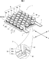
- the thermoelectric conversion module 1 according to the first embodiment shown in FIGS. 1 to 3 is a so-called unileg type in which a plurality of n-type thermoelectric conversion elements are electrically connected in series, and is an insulation formed of aluminum oxide.
- a pair of plate-like base portions 11 having the properties are provided.
- the base portion located above is omitted in order to make the inside of the thermoelectric conversion module 1 easy to see. 1 is necessary for reasons such as prevention of a short circuit when the thermoelectric conversion module 1 is used in contact with a heat source having a conductive exterior such as metal.
- thermoelectric conversion module 1 can be configured by leaving only the upper base portion and eliminating the lower base portion 11.
- An n-type thermoelectric conversion element 2 made of Mg 2 Si is disposed between the electrodes 3 and 4.
- thermoelectric conversion element As a material of the thermoelectric conversion element, BiTe type, PbTe type, CoSb type are used, all of which are harmful to the human body (including those that are feared to be harmful), It is also expensive.
- Mg 2 Si is harmless to the human body, has a small environmental load, is rich in resources, and is inexpensive. Moreover, since Mg 2 Si has a low specific gravity, a very light thermoelectric conversion element 2 can be produced. For this reason, in recent years, Mg 2 Si has attracted attention as a material for thermoelectric conversion elements.
- both bases 11 are not limited to aluminum oxide, and may be formed of other materials.
- the electrodes 3 and 4 are not limited to nickel (Ni) but may be made of other materials, for example, copper (Cu) plated with nickel (Ni).
- thermoelectric conversion element 2 One end of the thermoelectric conversion element 2 is joined to the first electrode 3, and the other end is joined to the second electrode 4.
- a joining method soldering, brazing, or the like, or adhesion or diffusion bonding using a conductive adhesive such as silver paste can be used, and it is appropriately selected and joined according to the use of the thermoelectric conversion module. .
- brazing When joining by brazing, brazing (solder) may be pasted to both ends of the thermoelectric conversion element 2 in advance.
- the surface of the thermoelectric conversion element 2 is a surface having fine irregularities, it can be made a smooth surface by covering the irregularities on the surface with solder (solder), silver paste, or the like, whereby the thermoelectric conversion element 2 As a result, the bonding state between the electrode 3 and the electrode 4 is improved, and excellent conductivity can be secured. Further, when the thermoelectric conversion element 2 is manufactured, a nickel layer may be formed on both ends of the thermoelectric conversion element 2.
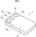
- the first electrode 3 includes an element arrangement part 31 for arranging the thermoelectric conversion element 2 and an extending part 32 extending from the element arrangement part 31 along the base 11. That is, the element arrangement part 31 is electrically connected to one end of the thermoelectric conversion element 2.
- the second electrode 4 has an element arrangement portion 41 for arranging the thermoelectric conversion element 2 and a quadrangular columnar rod-like shape extending from the side edge portion of the element arrangement portion 41 by bending in an L shape. And a connection unit 42. That is, the element arrangement portion 41 is electrically connected to the other end portion of the thermoelectric conversion element 2.
- the extension part 32 of the first electrode 3 is provided with three holes 33a, 33b, 33c into which the tip of the connection part 42 is inserted.
- the receiving part 33 is comprised by these three hole parts 33a, 33b, and 33c.
- the connection part 42 has its tip inserted into the receiving part 33 provided on the first electrode 3 and is joined by brazing or the like. Thereby, the 1st electrode 3 and the 2nd electrode 4 provided in the thermoelectric conversion element adjacent to the thermoelectric conversion element 2 in which the 1st electrode 3 was provided are electrically connected in series.
- the connection part 42 uses nickel (Ni) similarly to the electrodes 3 and 4, it is not restricted to this, You may use copper (Cu) which gave other metal, for example, nickel plating.
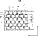
- thermoelectric conversion elements 2 constitute a plurality of element rows 6 arranged on the base 11 in the X-axis direction (five in the drawing). A plurality (6 in the drawing) of the element rows 6 are arranged in the Y-axis direction.
- one thermoelectric conversion module 1 includes 30 thermoelectric conversion elements 2.
- an input / output terminal 7 for taking out electricity is provided at one end of the thermoelectric conversion element 2 located at the right end of the element row 6 located at the top of FIG.
- the terminal 7 is formed in a rectangular shape that protrudes greatly out of the base portion 11 from the element placement portion 7a where the thermoelectric conversion element 2 is placed.
- an input / output terminal 7 for taking out electricity is provided at the other end of the thermoelectric conversion element 2 located at the right end of the element row 6 located at the bottom of FIG.
- the terminal 7 protrudes greatly out of the base 11 from the element arrangement portion 7a where the thermoelectric conversion element 2 is arranged, and is bent in a crank shape.
- the right end of the terminal 7 in FIG. 3 is configured to be located at the same height as the terminal 7 of the element row 6 located at the top.
- the element rows 6 are even rows, but they may be odd rows.
- the terminal 7 provided in the element array 6 located at the top of FIG. 3 may be provided in the first electrode 3 located at the left end. .
- the recessed part 32a is each provided in the right-and-left both sides edge part of the extending part 32.
- the recess 32 a is used when the first electrode 3 is disposed on the base 11.
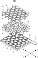
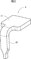
- the alignment member 8 shown in FIG. 6 is used.
- the alignment member 8 is provided with a plurality of cutout holes 8 a corresponding to the arrangement and shape of the plurality of first electrodes 3.
- thermoelectric conversion module 1 In assembling the thermoelectric conversion module 1, when the first electrode 3 is disposed on the base 11, the alignment member 8 is first installed on the base 11. Then, the first electrode 3 is fitted into the notch hole 8a.
- thermoelectric conversion module 1 of this embodiment it can prevent installing the 1st electrode 3 accidentally with respect to the base 11, and can aim at the improvement of a yield.
- the alignment member 8 used in the method for assembling the thermoelectric conversion module 1 of the present embodiment is also provided with a terminal notch hole 8c so that the terminal 7 can also be aligned.
- positioning part 31 the contact area with the thermoelectric conversion element 2 of the element arrangement
- the recess 32a in the extending portion 32 as described above, it is possible to prevent the first electrode 3 from being mistakenly arranged on the base portion 11 without reducing the arrangement area of the thermoelectric conversion element 2.
- convex portions may be formed on the left and right side edges of the extended portion 32 of the first electrode 3, and concave portions corresponding to the convex portions may be formed in the cutout holes 8a.
- the convex portion can be provided on the peripheral edge portion of the element arrangement portion 31.
- the recess or projection of the extended portion 32 may be formed at the tip (the end on the side away from the element placement portion 31). In this case, for example, one recess or projection is provided at the center Alternatively, two may be provided so as to be positioned between the holes and to be the left and right objects.
- the element rows 6 are arranged in order from the upper side to the lower side in the first element row 61, the second element row 62, the third element row 63, the fourth element row 64, the fifth element row 65, the first element row. It is defined as a six-element row 66, the first element row 61, the third element row 63, and the fifth element row 65 are odd-numbered rows, the second element row 62, the fourth element row 64, and the sixth element row 66 are even-numbered rows. Define.
- the first electrodes 3 in the odd rows 61, 63, 65 are arranged so that the extending portion 32 is positioned on the right side of the element placement portion 31.
- the first electrodes 3 in the even-numbered columns 62, 64, and 66 are arranged so that the extending portion 32 is positioned on the left side of the element placement portion 31, as shown in FIG. That is, in the thermoelectric conversion module 1 of the present embodiment, all the extending portions 32 are located in the X-axis direction of the element placement portion 31.
- the second electrodes 4 in the odd rows 61, 63, 65 are arranged so that the connection part 42 is located on the left side of the element arrangement part 41 except for the second electrode 4 located on the leftmost side. And the front-end
- the second electrodes 4 of the even-numbered columns 62, 64, and 66 are arranged such that the connection portion 42 is located on the right side of the element placement portion 41 except for the second electrode 4 located on the rightmost side. . And the front-end
- the second electrode 4 located on the leftmost side of the odd rows 61, 63, 65 is for electrically connecting the element rows 6 in series.
- tip of the connection part 42 is inserted in the hole 33a located in the right side of the receiving part 33, and is joined by brazing.
- connection portion 42 is disposed so as to be positioned below the element placement portion 41. And the front-end
- connection portion 42 is inserted into the central hole portion 33 b, and between the element rows 6, the connection portion 42 is inserted into the left and right hole portions 33 a and 33 c.
- the inside of the element rows 6 and between the element rows 6 can be electrically connected without changing the connection portion 42 having the same shape.
- thermoelectric conversion module 1 of the present embodiment it is possible to make the manufacturing easier than before while suppressing an increase in the number of parts as compared with the case where both electrodes and the connection portion are separated. .
- the 1st electrode 3 is also formed in the left-right symmetric shape by which the receiving part 33 was comprised by three hole part 33a, 33b, 33c, all the 1st electrodes 3 can be formed in the same shape. Moreover, since the 1st electrode 3 is a left-right symmetric shape, there is no difference in front and back, and it becomes easier to assemble.
- thermoelectric conversion module 1 is arranged so as to be positioned at the position.
- thermoelectric conversion module 1 of the present embodiment since the extended portions 32 of all the first electrodes 3 can be arranged in the X-axis direction of the element arrangement portion 31, the element density can be improved.
- the receiving portion 33 is configured by the three holes 33a, 33b, and 33c.
- the receiving portion of the present invention is not limited to this.
- the receiving part may be configured with one hole that is long in the left-right direction, or the left-side hole 33c may be omitted and the center and the right-side holes 33a and 33b may be configured.
- the first electrode 3 may be appropriately turned over so that the connecting part 42 extending from the adjacent element row 6 can be received by the right hole 33a.
- the thermoelectric conversion element 2 of this embodiment showed the square pillar-shaped thing in FIG. 2, it is good also as not only this but another shape, for example, a cylindrical shape.
- thermoelectric conversion module 1 of the present embodiment When the upper base (not shown) of the thermoelectric conversion module 1 is attached to a heat source of, for example, 300 ° C. to 600 ° C. and the base 11 is cooled, a temperature difference occurs at both ends of the thermoelectric conversion element 2 and current flows due to the Seebeck effect. Generate electricity. At this time, in order to continue power generation, it is necessary to maintain a predetermined temperature difference at both ends of the thermoelectric conversion element 2, but in the first embodiment, Mg 2 having a low thermal conductivity as the material of the thermoelectric conversion element 2 is used. Since Si is used, the temperature difference can be maintained satisfactorily.
- thermoelectric conversion element 2 since the connection portion 42 is integral with the second electrode 4 and separate from the first electrode 3, the thermoelectric conversion element 2 is attached to the first electrode 3 fixed to the base portion 11. And electrically connecting the second electrode 4 to the other end of the thermoelectric conversion element 2 and connecting the first electrode 3 and the second electrode 4 between the adjacent thermoelectric conversion elements 2. Can be connected to the receiving portion 33 of the first electrode 3 so that they are electrically connected. Therefore, unlike the conventional thermoelectric conversion module, it is not necessary to push the thermoelectric conversion element into the U-shaped connector, and the mass productivity of the thermoelectric conversion module is improved.
- thermoelectric conversion element 2 is made of Mg 2 Si, but is not limited thereto.
- Bi-Te system including Sb-Te system and Bi-Se system
- Pb-Te system including Sn-Te system and Ge-Te system
- Ag-Sb-Te system Ag-Sb-Ge-Te system
- Si-Ge Fe-Si, Mn-Si, Zn-Sb
- chalcogenite skutterudite, filled skutterudite, clathrate, half-Heusler, Heusler, boron carbide, layered cobalt oxide, etc.
- Any thermoelectric conversion material can be used.
- thermoelectric conversion element 2 is not limited to the n-type, and a p-type may be used.
- Mg 2 Si does not have to be highly pure, and may be obtained by using, for example, waste silicone sludge discharged during grinding / polishing.
- a bonding layer may be provided at both ends of the thermoelectric conversion element 2 in order to reduce the contact resistance with the electrode.
- the bonding layer can also be formed integrally with the thermoelectric conversion element.
- the bonding layer and the electrode can be made of any material such as Ni, Al, Cu, W, Au, Ag, Co, Mo, Cr, Ti, Pd, and an alloy made of these.
- thermoelectric conversion module 1 for power generation using the Seebeck effect has been described.
- thermoelectric conversion module of the present invention can be similarly used for those that are cooled or heated using the Peltier effect. it can.
- the misassembly prevention unit has been described as being configured by the recess 32a and the projection 8b shown in FIG. 6, but the misassembly prevention unit of the present invention is not limited thereto.
- a portion of the four corners of the first electrode is cut obliquely to provide a cut portion as a concave portion of the present invention, and the alignment member 8 also protrudes to correspond to the cut portion as the concave portion of the present invention
- the alignment member 8 By forming the (convex portion), it can be configured to prevent the element placement portion 31 and the extension portion 32 from being installed on the base portion 11 in an incorrect state.
- thermoelectric conversion module 1 shown in FIG. 1 is in contact with the heat source and the lower side where the lower side is radiated.
- the method of using the thermoelectric conversion module of the present invention is not limited to this.
- the upper side may be set to the low temperature side and the lower side may be set to the high temperature side.
- SYMBOLS 1 ... Thermoelectric conversion module, 11 ... Base, 2 ... Thermoelectric conversion element, 3 ... 1st electrode, 31 ... Element arrangement
Abstract
Description
また、n形又はp形の何れか一方の熱電変換素子の1種類だけで構成される所謂ユニレグ型の熱電変換モジュールも知られている(例えば、特許文献2参照)。 In the thermoelectric conversion module of
In addition, a so-called uni-leg type thermoelectric conversion module configured by only one type of either n-type or p-type thermoelectric conversion elements is also known (for example, see Patent Document 2).
本発明は、以上の点に鑑み、量産性を向上させた熱電変換モジュールを提供することを目的とする。 A conventional so-called unileg type thermoelectric conversion module has a problem that it is difficult to assemble and low in mass productivity because it is necessary to push a thermoelectric conversion element into a U-shaped connector.
An object of this invention is to provide the thermoelectric conversion module which improved mass productivity in view of the above point.
本発明によれば、第1電極を基部に対して誤って設置することを防止し、歩留まりの向上を図ることができる。 [3] In the present invention, the first electrode includes an extending portion extending from the element placement portion along the base, the receiving portion is provided in the extending portion, and the first electrode is erroneously formed on the base. In order to prevent it from being arranged, a misassembly prevention unit composed of a convex part or a concave part is provided.
According to the present invention, it is possible to prevent the first electrode from being erroneously installed with respect to the base, and to improve the yield.
また、本実施形態の熱電変換素子2は、図2に四角柱状のものを示したが、これに限らず、他の形状、例えば、円柱状としてもよい。 In the present embodiment, the receiving
Moreover, although the
Claims (4)
- 基部と、
複数の第1電極と、
一方の端部が前記第1電極と夫々電気的に接続される複数の熱電変換素子と、
該熱電変換素子の他方の端部に夫々電気的に接続される複数の第2電極と、
前記熱電変換素子に電気的に接続される前記第1電極を、隣接する前記熱電変換素子に電気的に接続される前記第2電極に、電気的に接続する接続部とを備え、
前記複数の熱電変換素子は、n形とp形との何れか一方で構成され、
前記複数の熱電変換素子が電気的に直列に接続される熱電変換モジュールであって、
前記接続部は、前記第2電極と一体に形成されると共に、前記第1電極と別体に構成され、
前記第1電極は、前記熱電変換素子の一方の端部と電気的に接触する素子配置部と、前記接続部の先端を受け入れる受入部とを備え、
前記第1電極または前記第2電極は、前記基部上に配置され、
前記基部に沿うと共に互いに直交する2つの軸線をX軸及びY軸として、
前記熱電変換素子は、前記基部上に前記X軸方向に複数並べられて素子列を構成し、
該素子列は、Y軸方向に複数並べられ、
該受入部は、前記素子列内において、前記素子配置部の前記X軸方向に位置し、前記接続部が素子列内の熱電変換素子を電気的に接続する場合と、前記接続部が隣接する素子列の間同士を電気的に接続する場合の何れであっても、同一形状の接続部で受け入れられるように構成され、
前記第1電極は、全て同一形状に構成され、
前記第2電極は、全て同一形状に構成されることを特徴とする熱電変換モジュール。 The base,
A plurality of first electrodes;
A plurality of thermoelectric conversion elements each having one end electrically connected to the first electrode;
A plurality of second electrodes respectively electrically connected to the other end of the thermoelectric conversion element;
A connection portion for electrically connecting the first electrode electrically connected to the thermoelectric conversion element to the second electrode electrically connected to the adjacent thermoelectric conversion element;
The plurality of thermoelectric conversion elements are configured in one of n-type and p-type,
The thermoelectric conversion module in which the plurality of thermoelectric conversion elements are electrically connected in series,
The connection portion is formed integrally with the second electrode, and is configured separately from the first electrode.
The first electrode includes an element arrangement portion that is in electrical contact with one end portion of the thermoelectric conversion element, and a receiving portion that receives the tip of the connection portion,
The first electrode or the second electrode is disposed on the base;
Two axes along the base and orthogonal to each other are taken as an X axis and a Y axis,
A plurality of the thermoelectric conversion elements are arranged in the X-axis direction on the base to constitute an element row,
A plurality of the element rows are arranged in the Y-axis direction,
The receiving portion is positioned in the X-axis direction of the element arrangement portion in the element row, and the connection portion is adjacent to the case where the connection portion electrically connects the thermoelectric conversion elements in the element row. In any case where the element rows are electrically connected to each other, it is configured to be received by a connection portion of the same shape,
The first electrodes are all configured in the same shape,
The thermoelectric conversion module, wherein the second electrodes are all configured in the same shape. - 請求項1に記載の熱電変換モジュールであって、
前記受入部は、複数の孔部で構成され、
前記複数の孔部のうち中央に位置する前記孔部が前記素子列内で前記接続部を受け入れる孔部であり、左右方向に位置する前記孔部が前記素子列の間で前記接続部を受け入れる孔部であることを特徴とする熱電変換モジュール。 The thermoelectric conversion module according to claim 1,
The receiving part is composed of a plurality of holes,
The hole located in the center of the plurality of holes is a hole that receives the connection part in the element row, and the hole located in the left-right direction accepts the connection part between the element rows. A thermoelectric conversion module characterized by being a hole. - 請求項1又は請求項2に記載の熱電変換モジュールであって、
前記第1電極は、前記素子配置部から前記基部に沿って延びる延設部を備え、
該延設部に前記受入部が設けられ、
前記第1電極は、前記基部上に誤って配置されることを防止すべく、凸部又は凹部で構成される誤組み防止部が設けられることを特徴とする熱電変換モジュール。 The thermoelectric conversion module according to claim 1 or 2, wherein
The first electrode includes an extending portion extending from the element placement portion along the base portion,
The extension part is provided with the receiving part,
The thermoelectric conversion module according to claim 1, wherein the first electrode is provided with a misassembly prevention portion including a convex portion or a concave portion to prevent the first electrode from being erroneously arranged on the base portion. - 請求項3に記載の熱電変換モジュールの組立て方法であって、
前記複数の第1電極の配置及び形状に対応する切欠孔を複数備える整列部材を、前記基部上に配置し、
前記切欠孔に前記第1電極を嵌め込むことにより、前記第1電極を前記基部上に配置することを特徴とする熱電変換モジュールの組立て方法。 A method for assembling the thermoelectric conversion module according to claim 3,
An alignment member including a plurality of cutout holes corresponding to the arrangement and shape of the plurality of first electrodes is disposed on the base;
A method of assembling a thermoelectric conversion module, wherein the first electrode is disposed on the base by fitting the first electrode into the cutout hole.
Priority Applications (4)
| Application Number | Priority Date | Filing Date | Title |
|---|---|---|---|
| CN201380071903.2A CN105122486B (en) | 2013-03-15 | 2013-12-10 | Thermo-electric conversion module |
| EP13877529.1A EP2975660B1 (en) | 2013-03-15 | 2013-12-10 | Thermoelectric conversion module |
| KR1020157017847A KR20150132085A (en) | 2013-03-15 | 2013-12-10 | Thermoelectric conversion module |
| US14/766,744 US9537076B2 (en) | 2013-03-15 | 2013-12-10 | Thermoelectric conversion module |
Applications Claiming Priority (2)
| Application Number | Priority Date | Filing Date | Title |
|---|---|---|---|
| JP2013-053768 | 2013-03-15 | ||
| JP2013053768A JP6009382B2 (en) | 2013-03-15 | 2013-03-15 | Thermoelectric conversion module |
Publications (1)
| Publication Number | Publication Date |
|---|---|
| WO2014141551A1 true WO2014141551A1 (en) | 2014-09-18 |
Family
ID=51536237
Family Applications (1)
| Application Number | Title | Priority Date | Filing Date |
|---|---|---|---|
| PCT/JP2013/083011 WO2014141551A1 (en) | 2013-03-15 | 2013-12-10 | Thermoelectric conversion module |
Country Status (6)
| Country | Link |
|---|---|
| US (1) | US9537076B2 (en) |
| EP (1) | EP2975660B1 (en) |
| JP (1) | JP6009382B2 (en) |
| KR (1) | KR20150132085A (en) |
| CN (1) | CN105122486B (en) |
| WO (1) | WO2014141551A1 (en) |
Families Citing this family (6)
| Publication number | Priority date | Publication date | Assignee | Title |
|---|---|---|---|---|
| JP6453067B2 (en) * | 2014-12-10 | 2019-01-16 | 日本サーモスタット株式会社 | Thermoelectric conversion module |
| KR20160137848A (en) * | 2015-05-22 | 2016-12-01 | 에스케이이노베이션 주식회사 | Thermoelectric materials, and thermoelectric module and thermoelectric apparatus comprising the same |
| JP6739072B2 (en) * | 2015-10-15 | 2020-08-12 | 国立研究開発法人産業技術総合研究所 | Method for producing thermoelectric conversion module |
| KR102528360B1 (en) * | 2016-09-02 | 2023-05-03 | 엘지이노텍 주식회사 | Thermo electric element and thermo electric module |
| TWI608638B (en) | 2016-12-15 | 2017-12-11 | 財團法人工業技術研究院 | Thermoelectric module |
| US11450797B2 (en) * | 2017-12-08 | 2022-09-20 | 3M Innovative Properties Company | Differential thermoelectric device |
Citations (12)
| Publication number | Priority date | Publication date | Assignee | Title |
|---|---|---|---|---|
| JPH08149866A (en) * | 1994-11-15 | 1996-06-07 | Nippondenso Co Ltd | Thermoelectric converter |
| JP2004152921A (en) * | 2002-10-30 | 2004-05-27 | Komatsu Ltd | Thermoelectric module and its manufacturing method |
| WO2005124881A1 (en) * | 2004-06-22 | 2005-12-29 | Aruze Corp. | Thermoelectric conversion element |
| WO2006004059A1 (en) * | 2004-07-01 | 2006-01-12 | Aruze Corp. | Thermoelectric conversion module |
| WO2008029451A1 (en) * | 2006-09-05 | 2008-03-13 | Pioneer Corporation | Thermal sound generating device |
| JP2009176919A (en) | 2008-01-24 | 2009-08-06 | Aruze Corp | Thermoelectric conversion module, and connector for thermoelectric conversion element |
| US20090277489A1 (en) * | 2005-12-09 | 2009-11-12 | Thierry Luc Alain Dannoux | Thermoelectric Device |
| US20100154854A1 (en) * | 2008-12-19 | 2010-06-24 | Samsung Electronics Co., Ltd. | Thermoelectric module comprising spherical thermoelectric elements and method of manufacturing the same |
| JP2010171071A (en) * | 2009-01-20 | 2010-08-05 | Universal Entertainment Corp | Thermoelectric conversion element, thermoelectric conversion module, and method of manufacturing thermoelectric conversion element |
| JP4834986B2 (en) | 2004-12-10 | 2011-12-14 | 株式会社Ihi | Thermoelectric unit |
| WO2012091048A1 (en) * | 2010-12-28 | 2012-07-05 | 京セラ株式会社 | Thermoelectric conversion member |
| WO2013080719A1 (en) * | 2011-11-30 | 2013-06-06 | 日本サーモスタット株式会社 | Thermoelectric conversion module |
Family Cites Families (15)
| Publication number | Priority date | Publication date | Assignee | Title |
|---|---|---|---|---|
| US3496028A (en) * | 1965-11-18 | 1970-02-17 | Minnesota Mining & Mfg | Thermoelectric generator apparatus |
| DE1539323A1 (en) * | 1966-06-08 | 1969-10-02 | Siemens Ag | Thermogenerator |
| DE1539330A1 (en) * | 1966-12-06 | 1969-11-06 | Siemens Ag | Thermoelectric arrangement |
| US3714539A (en) * | 1971-06-24 | 1973-01-30 | Minnesota Mining & Mfg | Pressure-contact structure for thermoelectric generators |
| US3884726A (en) * | 1972-05-11 | 1975-05-20 | Kurt Landecker | Thermoelectric element |
| US4497973A (en) * | 1983-02-28 | 1985-02-05 | Ecd-Anr Energy Conversion Company | Thermoelectric device exhibiting decreased stress |
| US6779347B2 (en) * | 2001-05-21 | 2004-08-24 | C.P. Baker Securities, Inc. | Solid-state thermionic refrigeration |
| WO2005074049A2 (en) * | 2004-01-16 | 2005-08-11 | Massachusetts Institute Of Technology | Potential amplified nonequilibrium thermal electric device (pantec) |
| CN100499195C (en) * | 2004-05-31 | 2009-06-10 | 株式会社电装 | Thermoelectric converter and its manufacturing method |
| US20070095381A1 (en) * | 2005-10-28 | 2007-05-03 | Taiwan Semiconductor Manufacturing Co., Ltd. | Stacked thermoelectric device for power generation |
| CN101499467A (en) * | 2008-01-29 | 2009-08-05 | 京瓷株式会社 | Thermoelectric module |
| JP5499317B2 (en) * | 2009-03-03 | 2014-05-21 | 学校法人東京理科大学 | Thermoelectric conversion element and thermoelectric conversion module |
| WO2010113257A1 (en) * | 2009-03-31 | 2010-10-07 | 富士通株式会社 | Thermoelectric conversion module and method for recovering the same |
| US20110139203A1 (en) * | 2009-12-16 | 2011-06-16 | Gm Global Technology Operations, Inc. | Heterostructure thermoelectric generator |
| JP5686130B2 (en) | 2012-12-27 | 2015-03-18 | トヨタ自動車株式会社 | Method for producing solid lithium secondary battery |
-
2013
- 2013-03-15 JP JP2013053768A patent/JP6009382B2/en not_active Expired - Fee Related
- 2013-12-10 EP EP13877529.1A patent/EP2975660B1/en not_active Not-in-force
- 2013-12-10 KR KR1020157017847A patent/KR20150132085A/en not_active Application Discontinuation
- 2013-12-10 CN CN201380071903.2A patent/CN105122486B/en not_active Expired - Fee Related
- 2013-12-10 WO PCT/JP2013/083011 patent/WO2014141551A1/en active Application Filing
- 2013-12-10 US US14/766,744 patent/US9537076B2/en not_active Expired - Fee Related
Patent Citations (12)
| Publication number | Priority date | Publication date | Assignee | Title |
|---|---|---|---|---|
| JPH08149866A (en) * | 1994-11-15 | 1996-06-07 | Nippondenso Co Ltd | Thermoelectric converter |
| JP2004152921A (en) * | 2002-10-30 | 2004-05-27 | Komatsu Ltd | Thermoelectric module and its manufacturing method |
| WO2005124881A1 (en) * | 2004-06-22 | 2005-12-29 | Aruze Corp. | Thermoelectric conversion element |
| WO2006004059A1 (en) * | 2004-07-01 | 2006-01-12 | Aruze Corp. | Thermoelectric conversion module |
| JP4834986B2 (en) | 2004-12-10 | 2011-12-14 | 株式会社Ihi | Thermoelectric unit |
| US20090277489A1 (en) * | 2005-12-09 | 2009-11-12 | Thierry Luc Alain Dannoux | Thermoelectric Device |
| WO2008029451A1 (en) * | 2006-09-05 | 2008-03-13 | Pioneer Corporation | Thermal sound generating device |
| JP2009176919A (en) | 2008-01-24 | 2009-08-06 | Aruze Corp | Thermoelectric conversion module, and connector for thermoelectric conversion element |
| US20100154854A1 (en) * | 2008-12-19 | 2010-06-24 | Samsung Electronics Co., Ltd. | Thermoelectric module comprising spherical thermoelectric elements and method of manufacturing the same |
| JP2010171071A (en) * | 2009-01-20 | 2010-08-05 | Universal Entertainment Corp | Thermoelectric conversion element, thermoelectric conversion module, and method of manufacturing thermoelectric conversion element |
| WO2012091048A1 (en) * | 2010-12-28 | 2012-07-05 | 京セラ株式会社 | Thermoelectric conversion member |
| WO2013080719A1 (en) * | 2011-11-30 | 2013-06-06 | 日本サーモスタット株式会社 | Thermoelectric conversion module |
Non-Patent Citations (1)
| Title |
|---|
| See also references of EP2975660A4 |
Also Published As
| Publication number | Publication date |
|---|---|
| JP2014179539A (en) | 2014-09-25 |
| CN105122486B (en) | 2017-07-18 |
| JP6009382B2 (en) | 2016-10-19 |
| EP2975660A1 (en) | 2016-01-20 |
| US9537076B2 (en) | 2017-01-03 |
| EP2975660B1 (en) | 2018-02-21 |
| EP2975660A4 (en) | 2016-12-14 |
| US20160005947A1 (en) | 2016-01-07 |
| CN105122486A (en) | 2015-12-02 |
| KR20150132085A (en) | 2015-11-25 |
Similar Documents
| Publication | Publication Date | Title |
|---|---|---|
| JP5913935B2 (en) | Thermoelectric conversion module | |
| JP6009382B2 (en) | Thermoelectric conversion module | |
| JP6193709B2 (en) | Thermoelectric conversion module | |
| US9793462B2 (en) | Thermoelectric module, thermoelectric power generating apparatus, and thermoelectric generator | |
| US5254178A (en) | Thermoelectric transducer apparatus comprising N- and P-type semiconductors and having electronic control capabilities | |
| CN108305935A (en) | Flexible thermo-electric device and preparation method | |
| JP2018137374A (en) | Thermoelectric conversion module and method of manufacturing thermoelectric conversion module | |
| JP2019062054A (en) | Thermoelectric conversion cell and thermoelectric conversion module | |
| EP3232483B1 (en) | Thermoelectric conversion module | |
| US10672968B2 (en) | Thermoelectric devices | |
| JP7162792B2 (en) | Thermoelectric conversion module | |
| JP2006287066A (en) | Thermoelectric conversion apparatus and method of manufacturing the apparatus | |
| JP4294965B2 (en) | Thermoelectric conversion module | |
| JP2020088018A (en) | Thermoelectric module, thermoelectric element component, thermoelectric element component manufacturing method, and thermoelectric module manufacturing method |
Legal Events
| Date | Code | Title | Description |
|---|---|---|---|
| 121 | Ep: the epo has been informed by wipo that ep was designated in this application |
Ref document number: 13877529 Country of ref document: EP Kind code of ref document: A1 |
|
| ENP | Entry into the national phase |
Ref document number: 20157017847 Country of ref document: KR Kind code of ref document: A |
|
| WWE | Wipo information: entry into national phase |
Ref document number: 14766744 Country of ref document: US |
|
| WWE | Wipo information: entry into national phase |
Ref document number: 2013877529 Country of ref document: EP |
|
| NENP | Non-entry into the national phase |
Ref country code: DE |