WO2014136641A1 - 体動表示装置および体動表示方法 - Google Patents
体動表示装置および体動表示方法 Download PDFInfo
- Publication number
- WO2014136641A1 WO2014136641A1 PCT/JP2014/054787 JP2014054787W WO2014136641A1 WO 2014136641 A1 WO2014136641 A1 WO 2014136641A1 JP 2014054787 W JP2014054787 W JP 2014054787W WO 2014136641 A1 WO2014136641 A1 WO 2014136641A1
- Authority
- WO
- WIPO (PCT)
- Prior art keywords
- body movement
- display
- image
- body motion
- index value
- Prior art date
- Legal status (The legal status is an assumption and is not a legal conclusion. Google has not performed a legal analysis and makes no representation as to the accuracy of the status listed.)
- Ceased
Links
Images





Classifications
-
- A—HUMAN NECESSITIES
- A61—MEDICAL OR VETERINARY SCIENCE; HYGIENE
- A61B—DIAGNOSIS; SURGERY; IDENTIFICATION
- A61B6/00—Apparatus or devices for radiation diagnosis; Apparatus or devices for radiation diagnosis combined with radiation therapy equipment
- A61B6/52—Devices using data or image processing specially adapted for radiation diagnosis
- A61B6/5258—Devices using data or image processing specially adapted for radiation diagnosis involving detection or reduction of artifacts or noise
- A61B6/5264—Devices using data or image processing specially adapted for radiation diagnosis involving detection or reduction of artifacts or noise due to motion
-
- A—HUMAN NECESSITIES
- A61—MEDICAL OR VETERINARY SCIENCE; HYGIENE
- A61B—DIAGNOSIS; SURGERY; IDENTIFICATION
- A61B6/00—Apparatus or devices for radiation diagnosis; Apparatus or devices for radiation diagnosis combined with radiation therapy equipment
- A61B6/46—Arrangements for interfacing with the operator or the patient
- A61B6/461—Displaying means of special interest
-
- A—HUMAN NECESSITIES
- A61—MEDICAL OR VETERINARY SCIENCE; HYGIENE
- A61B—DIAGNOSIS; SURGERY; IDENTIFICATION
- A61B6/00—Apparatus or devices for radiation diagnosis; Apparatus or devices for radiation diagnosis combined with radiation therapy equipment
- A61B6/46—Arrangements for interfacing with the operator or the patient
- A61B6/461—Displaying means of special interest
- A61B6/463—Displaying means of special interest characterised by displaying multiple images or images and diagnostic data on one display
-
- A—HUMAN NECESSITIES
- A61—MEDICAL OR VETERINARY SCIENCE; HYGIENE
- A61B—DIAGNOSIS; SURGERY; IDENTIFICATION
- A61B6/00—Apparatus or devices for radiation diagnosis; Apparatus or devices for radiation diagnosis combined with radiation therapy equipment
- A61B6/46—Arrangements for interfacing with the operator or the patient
- A61B6/467—Arrangements for interfacing with the operator or the patient characterised by special input means
-
- A—HUMAN NECESSITIES
- A61—MEDICAL OR VETERINARY SCIENCE; HYGIENE
- A61B—DIAGNOSIS; SURGERY; IDENTIFICATION
- A61B6/00—Apparatus or devices for radiation diagnosis; Apparatus or devices for radiation diagnosis combined with radiation therapy equipment
- A61B6/52—Devices using data or image processing specially adapted for radiation diagnosis
- A61B6/5211—Devices using data or image processing specially adapted for radiation diagnosis involving processing of medical diagnostic data
-
- G—PHYSICS
- G06—COMPUTING OR CALCULATING; COUNTING
- G06T—IMAGE DATA PROCESSING OR GENERATION, IN GENERAL
- G06T7/00—Image analysis
-
- G—PHYSICS
- G06—COMPUTING OR CALCULATING; COUNTING
- G06T—IMAGE DATA PROCESSING OR GENERATION, IN GENERAL
- G06T7/00—Image analysis
- G06T7/20—Analysis of motion
-
- G—PHYSICS
- G16—INFORMATION AND COMMUNICATION TECHNOLOGY [ICT] SPECIALLY ADAPTED FOR SPECIFIC APPLICATION FIELDS
- G16H—HEALTHCARE INFORMATICS, i.e. INFORMATION AND COMMUNICATION TECHNOLOGY [ICT] SPECIALLY ADAPTED FOR THE HANDLING OR PROCESSING OF MEDICAL OR HEALTHCARE DATA
- G16H50/00—ICT specially adapted for medical diagnosis, medical simulation or medical data mining; ICT specially adapted for detecting, monitoring or modelling epidemics or pandemics
- G16H50/50—ICT specially adapted for medical diagnosis, medical simulation or medical data mining; ICT specially adapted for detecting, monitoring or modelling epidemics or pandemics for simulation or modelling of medical disorders
-
- G—PHYSICS
- G16—INFORMATION AND COMMUNICATION TECHNOLOGY [ICT] SPECIALLY ADAPTED FOR SPECIFIC APPLICATION FIELDS
- G16Z—INFORMATION AND COMMUNICATION TECHNOLOGY [ICT] SPECIALLY ADAPTED FOR SPECIFIC APPLICATION FIELDS, NOT OTHERWISE PROVIDED FOR
- G16Z99/00—Subject matter not provided for in other main groups of this subclass
-
- G—PHYSICS
- G06—COMPUTING OR CALCULATING; COUNTING
- G06T—IMAGE DATA PROCESSING OR GENERATION, IN GENERAL
- G06T2207/00—Indexing scheme for image analysis or image enhancement
- G06T2207/10—Image acquisition modality
- G06T2207/10116—X-ray image
-
- G—PHYSICS
- G06—COMPUTING OR CALCULATING; COUNTING
- G06T—IMAGE DATA PROCESSING OR GENERATION, IN GENERAL
- G06T2207/00—Indexing scheme for image analysis or image enhancement
- G06T2207/20—Special algorithmic details
- G06T2207/20016—Hierarchical, coarse-to-fine, multiscale or multiresolution image processing; Pyramid transform
-
- G—PHYSICS
- G06—COMPUTING OR CALCULATING; COUNTING
- G06T—IMAGE DATA PROCESSING OR GENERATION, IN GENERAL
- G06T2207/00—Indexing scheme for image analysis or image enhancement
- G06T2207/30—Subject of image; Context of image processing
- G06T2207/30004—Biomedical image processing
- G06T2207/30008—Bone
- G06T2207/30012—Spine; Backbone
-
- G—PHYSICS
- G06—COMPUTING OR CALCULATING; COUNTING
- G06T—IMAGE DATA PROCESSING OR GENERATION, IN GENERAL
- G06T2207/00—Indexing scheme for image analysis or image enhancement
- G06T2207/30—Subject of image; Context of image processing
- G06T2207/30168—Image quality inspection
Definitions
- the present invention relates to a body motion display device and a body motion display method for displaying body motion of a subject at the time of capturing a radiographic image.
- the acquired radiographic image is blurred due to body movement that causes the subject to move during imaging, and the image quality is low. It may deteriorate.
- the subject is a part of the neck, chest, abdomen, waist, etc. where the irradiation time of the radiation is long, or if a child is photographed, body movement is likely to occur, so degradation of the radiographic image is a problem. It becomes.
- the presence or absence of such body movement can be determined by an imaging technician by observing the state of the subject being shot and immediately confirming the acquired radiation image.
- the monitor in the imaging room often has a low resolution and displays a reduced radiographic image, and the observation environment is often relatively bright. For this reason, it is difficult to determine the presence or absence of body movement by observing the displayed radiographic image.
- the presence or absence of body movement is determined by enlarging the radiographic image and checking the entire body movement of the radiographic image while moving the area to be enlarged on the radiographic image.
- such an operation reduces the workflow of the radiographer who performs imaging.
- a method for automatically detecting body movement based on a radiographic image and displaying the detection result has been proposed. For example, learning of edge degradation included in a radiographic image as feature quantities in two vertical and horizontal directions, setting multiple regions of interest on the radiographic image, extracting edges from each region of interest, and learning The probability that body motion in the region of interest is included is calculated based on the extracted feature amount and the extracted edge, and it is determined for each region of interest whether blurring due to body motion occurs in the radiographic image based on the calculated probability.
- a technique has been proposed (see Patent Document 1).
- the radiographic image and the frame of the region of interest are displayed so as to overlap each other, and the region of interest including the body movement is different from the other regions of interest in the color of the frame. It makes it easy to recognize the presence or absence of body movement.
- a numerical value indicating the probability that the region of interest includes body motion is also displayed. Further, the selected region of interest is enlarged and displayed next to the radiographic image to facilitate confirmation of body movement.
- Patent Literature 1 can determine the presence or absence of body movement for each of a plurality of regions of interest, even if body movements of the same size occur in the same direction in each region of interest, all regions of interest Therefore, the efficiency of the confirmation operation for the presence or absence of body movement is not so good. Further, the method described in Patent Document 2 is to enlarge and display a radiographic image when there is a body movement, and it is necessary for an engineer to search for a part where there is a body movement.
- This invention is made in view of the said situation, and it aims at enabling it to perform more efficiently the operation
- the body movement display device includes an index value calculation unit that calculates an index value representing the degree of body movement of a subject included in a radiographic image in a plurality of portions on the radiographic image; It is characterized by comprising display control means for selectively displaying at least one of a plurality of body movement information based on index values in a plurality of portions on a display means.
- the display control means selectively selects at least one of the body motion information as a radiation image. It is good also as a means to superimpose and display on a display means.
- the body movement information may be a mark having a different color and / or shape depending on the size of the index value.
- the body motion information may be a vector corresponding to the size and orientation of the index value.
- the display control means may display the number of body movement information according to the display characteristics of the display means.
- the body motion information may include enlarged images of a plurality of parts.
- the display control means may change at least one of the display range of the enlarged image and the enlargement ratio of the enlarged image according to the part of the subject.
- the display control means may change at least one of the display range of the enlarged image and the enlargement ratio of the enlarged image according to the display characteristics of the display means.
- the display control means may display a reference image, which is referred to in determining whether or not there is body movement, on the display means together with body movement information.
- the display control means may display body movement information on the part for which the index value that is a specific value is calculated on the display means.
- the body movement display method calculates an index value representing the degree of body movement of a subject included in a radiation image in a plurality of portions on the radiation image, At least one of a plurality of pieces of body motion information based on index values in a plurality of portions is selectively displayed on a display means.
- an index value representing the degree of body movement of a subject included in a radiographic image is calculated in a plurality of portions on the radiographic image, and a plurality of index values based on the index values in the plurality of portions are calculated. At least one of the body motion information is selectively displayed on the display means. For this reason, it is suppressed that body motion information is displayed too much about a plurality of parts, and as a result, the check operation of the presence or absence of body motion can be performed efficiently.
- FIG. 1 Schematic which shows the structure of the radiographic imaging system to which the body movement display apparatus by the 1st Embodiment of this invention is applied.
- the figure which shows the state which displayed the mark as body movement information on the radiographic image The figure which shows the state which displayed the vector as body movement information on the radiographic image
- the figure which shows the state which displayed the enlarged image as body movement information on a radiographic image The figure which shows the state which displayed the radiographic image and its enlarged image, and the reference image side by side
- FIG. 1 is a schematic diagram showing a configuration of a radiographic image capturing system to which a body movement display device according to a first embodiment of the present invention is applied.
- the radiographic image capturing system captures a subject to acquire a radiographic image G0 of the subject, and detects the body motion based on the radiographic image G0.
- the signal processing unit 20 includes a display device, an input unit 30 for giving various instructions to the signal processing unit 20, and a display unit 40 that displays a radiographic image or the like acquired by imaging.
- the imaging apparatus 10 includes a radiation tube 12 that irradiates the subject H with radiation R, an imaging control unit 13 that controls driving of the radiation tube 12, and an imaging table 14 on which the subject H is placed.
- the imaging table 14 is provided with a radiation detector 11 that outputs a radiation detection signal of the subject H.
- the radiation detector 11 outputs a radiation detection signal corresponding to the energy level of irradiation radiation for each pixel arranged in a matrix.
- the detection signal is subjected to A / D conversion processing, and the radiation image G0 of the subject H is output. Is output as a digital image signal.
- the radiation detector 11 for example, as described in JP-A-7-72253, a scintillator that emits visible light upon irradiation with radiation and a solid-state light detecting element that detects the visible light are used. What is laminated or has a radiation photoconductive layer that outputs an electrical signal corresponding to the energy upon irradiation with radiation, as described in, for example, JP-A-2010-206067 Can be applied.
- the signal processing unit 20 includes a preprocessing unit 21 to which a digital image signal representing the radiation image G0 is input, a multi-resolution conversion unit 22, an analysis point setting unit 23, a contrast calculation unit 24, an index value calculation unit 25, and a display control unit. 26.
- the index value calculation unit 25 and the display control unit 26 constitute a body movement display device.
- the input unit 30 includes, for example, a keyboard 31 and a mouse 32, and inputs various instructions to a signal processing unit 20 by a user such as a radiographer.
- the display unit 40 is composed of, for example, a liquid crystal display, a CRT display, or the like, and displays body movement information regarding the movement of the subject H, a determination result of the presence or absence of body movement, a radiographic image of the photographed subject, and the like as necessary. .
- the signal processing unit 20, the input unit 30, and the display unit 40 described above can be configured from a computer system such as a general personal computer.
- radiographic imaging In capturing a radiation image, the radiation detector 11 is placed on the imaging table 14 of the imaging apparatus 10 and the subject H is placed thereon. By operating the imaging control unit 13 in this state, the radiation tube 12 is driven, and the radiation R passes through the subject H and is irradiated onto the radiation detector 11. When imaging is completed, a digital image signal representing the radiation image G0 is acquired from the radiation detector 11. The radiation image G0 can be reproduced and displayed on the display unit 40.
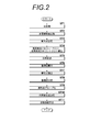
- FIG. 2 is a flowchart showing processing performed in the signal processing unit 20.
- the radiation image G0 input to the signal processing unit 20 is first processed in the preprocessing unit 21 to correct signal value fluctuations caused by radiation irradiation unevenness and detection unevenness of the radiation detector 11, and the image quality of the radiation image G0.
- Image processing for improving the density, contrast, frequency component, etc. for improving the image quality, and other processing appropriately performed as necessary preprocessing, step ST1).
- the multi-resolution conversion unit 22 performs multi-resolution conversion on the preprocessed radiation image G0, and extracts the high-frequency component and the low-frequency component of the radiation image G0 (step ST2).
- FIG. 3 is a diagram for explaining multi-resolution conversion.
- the Gaussian component G1 is the radiation image G0 reduced to 1 ⁇ 2.
- the multi-resolution conversion unit 22 performs an interpolation operation such as cubic B-spline interpolation to enlarge the Gaussian component G1 to the same size as the radiation image G0, and subtracts the enlarged Gaussian component G1 from the radiation image G0.
- the Laplacian component L0 in the highest frequency band is generated. In this embodiment, this Laplacian component L0 is used as a high frequency component. In the present embodiment, the highest frequency band is referred to as the 0th frequency band for convenience. *
- the above process is repeated until the Laplacian component L3 in the third frequency band is obtained, and the Laplacian component L3 is enlarged by a factor of 8 so as to be the same size as the Laplacian component L0 in the first frequency band.
- a Laplacian component L3 ′ is generated.
- the Laplacian component L3 ′ is used as a low frequency component.
- the signal value of each pixel of the Gaussian component represents the density of the pixel
- the signal value of each pixel of the Laplacian component represents the magnitude of the frequency component of the frequency band in the pixel.
- a plurality of band images having different frequency bands are generated, and the band image of the highest frequency band is converted to the high frequency component, and the third frequency band similar to the above.
- An image obtained by enlarging the band image by 8 times may be used as the low frequency component.
- the frequency band of the low frequency component is not limited to the third frequency band, and any frequency component in any frequency band can be used as the low frequency component as long as the frequency band is lower than the highest frequency band.
- the radiographic image G0 itself may be used as the high frequency component.
- the analysis point setting unit 23 sets an analysis point for calculating a contrast, which will be described later, in the pre-processed radiation image G0 (step ST3). Specifically, an analysis point is set using the low frequency component L3 ′. Hereinafter, setting of analysis points will be described.
- the analysis point setting unit 23 excludes the influence of the skin line and the irradiation field frame included in the radiation image G0, and limits the target for detecting body movement to the subject region including the bone part included in the radiation image G0.
- a subject region is extracted from the radiation image G0. Specifically, the subject region is extracted from the radiation image G0 using various segmentation techniques such as a method using the learning result for the subject to be studied, a rule-based method for the subject, and a graph cut method.
- the analysis point is preferably extracted on a part where it is easy to determine the presence or absence of body movement, specifically on the edge of the bone part. For this reason, the analysis point setting unit 23 sets a pixel having a relatively high pixel value from the subject area A0 in the low-frequency component L3 ′ generated by the multi-resolution conversion unit 22 as an analysis point.
- An example of analysis points set in this way is shown in FIG.
- the contrast calculation unit 24 calculates the high-frequency component contrast and the low-frequency component contrast at the analysis point (step ST4).
- body movement appears as blurring in one direction.
- the radiation image G0 deteriorates in the same direction as the body movement direction, but does not deteriorate in a direction perpendicular to the body movement direction. Therefore, the contrast calculation unit 24 first calculates the gradient direction of the edge at each analysis point. Specifically, the contrast calculation unit 24 sets eight directions around the analysis point P0 on the low frequency component L3 ′ as shown in FIG.
- the direction from the bottom to the top of the page is the reference (0 degree)
- Eight directions of degrees and 90 degrees are set.
- the eight directions are defined as ⁇ 1 to ⁇ 8, respectively.
- the direction to be set is not limited to 8, and can be any number such as 2 directions, 4 directions, or 16 directions.
- an analysis area having a specific size centered on the analysis point P0 is set.
- the analysis area is a rectangular area of 9 ⁇ 9 pixels, for example.
- a plurality of lines are virtually set in the analysis region, and a difference value between the maximum value and the minimum value of the pixel values in each line is calculated as the contrast in each line.
- the direction of the line is matched with the direction in which the analysis region is set. For example, when the analysis region is set in the direction ⁇ 1 shown in FIG. 5, the line direction set in the analysis region is ⁇ 1.
- FIG. 6 is a diagram for explaining the analysis region and horizontal lines.
- a plurality of lines are set in the analysis region A2 set in the direction ⁇ 1 where the analysis point P0 is located.
- the number of lines may be the same as the number of pixels in the vertical direction of the analysis area A2. That is, if the size of the analysis area A2 is 9 ⁇ 9 pixels, the number of lines may be nine. The number of lines may be reduced by thinning out as appropriate.
- the contrast of the high-frequency component is reduced in the acquired radiographic image G0, but the contrast of the low-frequency component is hardly reduced. Further, the contrast of the entire radiation image varies depending on the imaging condition or the type of subject, but the variation appears as a difference in contrast between low frequency components. Therefore, the ratio between the high frequency component contrast and the low frequency component contrast can be used as an index value representing the degree of body movement.
- the calculation of the index value indicating the degree of body movement is not limited to the above method, and the ratio CR ⁇ i of the high-frequency component contrast CH ⁇ i and the low-frequency component contrast CL ⁇ i in all eight directions at each analysis point is calculated.
- the average value CRm ⁇ i of the ratio CR ⁇ i of the high-frequency component contrast CH ⁇ i and the low-frequency component contrast CL ⁇ i for all the analysis points is calculated for each direction ⁇ i, and the lowest average value CRmL among these average values is calculated. It may be calculated as an index value representing the degree of.
- the display control unit 26 selectively displays at least one of the plurality of body motion information based on the index values at the plurality of analysis points on the display unit 40.
- selective display of body motion information will be described.
- the display control unit 26 first compares the index value at each analysis point with the threshold value Th1, and extracts an analysis point at which the index value is less than the threshold value Th1 from the plurality of analysis points (step ST7). ).
- the threshold value Th1 is a predetermined value smaller than 1.
- the display control unit 26 classifies the index values of the extracted analysis points into a plurality of levels (step ST8). In the present embodiment, classification is made in three stages, but the number of classifications is not limited to this.
- FIG. 7 is a diagram showing a histogram in which the index value is plotted on the horizontal axis and the number of analysis points is plotted on the vertical axis. As shown in FIG. 7, the display control unit 26 further classifies the portion of the histogram where the index value is less than the threshold value Th1 into three regions H1 to H3. Here, in the areas H1 to H3, the smaller the index value, the larger the body movement.
- the display control unit 26 adds marks with different colors according to the size of the index values to the analysis points classified into the regions H1 to H3. Display as body movement information. For example, red, blue, and white marks are displayed in ascending order of index values, that is, in descending order of body movement.
- the display control unit 26 confirms the direction and magnitude of the body movement (that is, the magnitude of the index value) at each analysis point, and the analysis point at which the direction and magnitude of the body movement are the same between adjacent analysis points. Are grouped (step ST9).
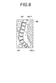
- FIG. 8 shows the result of grouping. In FIG. 8, it is assumed that a plurality of analysis points are grouped into three groups Gr1 to Gr3.
- the display control unit 26 determines representative analysis points that represent the groups Gr1 to Gr3 (step ST10). Since group Gr2 includes a large number of analysis points, the group Gr2 is appropriately divided into a plurality of groups (here, two groups Gr2-1 and Gr2-2), and one representative is represented in each group Gr2-1 and Gr2-2. The analysis point shall be determined.
- the representative analysis point may be, for example, the analysis point located at the center of each group Gr1 to Gr3.
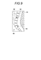
- FIG. 9 is a diagram showing a radiation image G0 displaying a mark. Note that what is displayed on the display unit 0 is the subject area A0 in the radiation image G0, but in the following description, the radiation image G0 is assumed to be displayed. As shown in FIG. 9, triangular marks M1 to M4 having different colors are displayed at the representative analysis points of the groups Gr1, Gr2-1, Gr2-2, and Gr3. Here, in FIG. 9, the fact that the colors are different is represented by changing the manner of filling the triangles. Note that the shape of the mark may be changed according to the size of the index value instead of the color, or the shape of the mark may be changed together with the color.
- the first embodiment since at least one of the plurality of body motion information based on the index value is selectively displayed on the display unit 40, all the bodies for the plurality of analysis points are displayed. The movement information is not displayed, and as a result, the confirmation of the presence or absence of body movement can be performed efficiently.
- the body movement information is a mark having a different color according to the size of the index value, it is easy to select a part to be observed due to the body movement based on the difference in color.
- the body movement information about the analysis point that is an index value that is less than the threshold value Th1 is displayed, it is possible to easily identify a portion that has body movement and should be observed.
- analysis points having the same direction and size of body movement are grouped and the body movement information is displayed at the position of the representative analysis point of each group.
- the representative analysis point may be determined based on the distance between the points and the similarity of the direction and size of the body movement. For example, if the direction and magnitude of body motion are greater than or equal to a predetermined similarity for an analysis point and another analysis point that is closest to the analysis point, the two analysis points are in the same group Any one analysis point is left as it belongs to and the other analysis point is deleted. This is repeated for all analysis points. Finally, the remaining analysis points are determined as representative analysis points of a group of analysis points with similar body movement directions and magnitudes, and the body is located at the position of the representative analysis point. You may make it display the direction and magnitude
- a vector corresponding to the magnitude and direction of body movement may be displayed on the radiation image G0 as body movement information.
- the size of the vector is different depending on the size of the index value, but at least one of the thickness, line type, and color of the vector is changed according to the size of the body movement. May be. Accordingly, it is possible to easily estimate the cause of the body movement, and as a result, it is possible to easily take measures such as fixing a portion where the body movement occurs when performing re-imaging.
- the display characteristics of the display unit 40 specifically, the resolution, display brightness, display range, and the like of the display unit 40.
- the resolution of the display unit 40 is low, if a large amount of body motion information is displayed, it is difficult to confirm body motion. For this reason, by displaying the number of body motion information corresponding to the display characteristics of the display unit 40, the body motion can be confirmed more easily.
- a mark or the like indicating the size of the index value is displayed as body movement information.
- an enlarged image obtained by enlarging a region centered on the analysis point is displayed as body movement information. May be.
- this will be described as a second embodiment.
- the analysis point for displaying the enlarged image is determined in the same manner as in the first embodiment. That is, analysis points whose body movements are in the same direction are grouped, and representative analysis points representing each group are determined. Then, an area of a certain size centered on the representative analysis point is set on the radiation image G0, and enlarged images of the respective areas are displayed side by side on the radiation image G0.
- FIG. 11 is a diagram for explaining the display of body motion information in the second embodiment. As shown in FIG. 11, rectangular areas A11 to A14 centering on each analysis point are set for four analysis points. Then, the enlarged images of the respective regions A11 to A14 are displayed as body movement information in the radiation image G0.
- the size of the enlarged image is preferably about 1 ⁇ 4 to 1 ⁇ 2 of the screen size on the display unit 40.
- a plurality of enlarged images may be displayed so as to be sequentially switchable.
- the display range and the enlargement ratio of the enlarged image suitable for confirmation of the body movement differ depending on the portion of the subject H to be displayed. For this reason, at least one of the display range of the enlarged image and the enlargement ratio may be changed according to the display characteristics of the display unit 40. Thereby, confirmation of the body movement using an enlarged image can be performed more easily. For example, when the part to be observed is the bone of the subject H, the ease of recognizing the edge becomes more important. For this reason, when observing a bone, displaying it larger than when observing a soft tissue or the like makes it easier to confirm the body movement of the bone.
- the display range and enlargement ratio of the enlarged image suitable for confirmation of body movement differ depending on the display characteristics of the display unit 40. For this reason, at least one of the display range of the enlarged image and the enlargement ratio may be changed according to the display characteristics of the display unit 40. Thereby, confirmation of the body movement using an enlarged image can be performed more easily.
- the radiographic image G0 in which the presence or absence of body movement is confirmed and the index value for the radiographic image G0 are stored in a database connected to the radiographic imaging system or provided in the system.
- FIG. 12 is a diagram showing a state in which the radiation image G0 and its enlarged image and reference image are displayed side by side. As shown in FIG. 12, by displaying the reference image R0 side by side with the radiation image G0 and the enlarged image, it is possible to easily check whether or not the enlarged image includes body movement using the reference image R0. Therefore, the confirmation work of the presence or absence of body movement can be performed more efficiently.
- the reference image R0 not only an index value that is relatively close to the index value calculated for the target radiographic image G0, but also a radiographic image determined to have no body movement may be used as the reference image R0. Even in this case, by referring to the reference image R0, it is possible to easily check whether or not the enlarged image includes body movements, so that the work for checking the presence or absence of body movements can be performed more efficiently. Can do.
- FIG. 13 is a diagram showing a state in which both the mark and the enlarged image are displayed.
- marks M1 to M4 are displayed in the radiation image G0 as in the first embodiment, and the analysis points to which the marks M1 to M4 are given are the center.
- the enlarged images of certain areas A11 to A14 are displayed side by side with the radiation image G0. Thereby, confirmation of the presence or absence of a body movement can be performed more easily.
- the subject H needs to be re-photographed.
- the influence of body movement can be reduced by setting the radiation irradiation time short during re-imaging.
- the imaging current condition is that the tube current is 300 mA and the irradiation time is 50 msec.
- photographing conditions with a short irradiation time are set. Thereby, the influence of body movement can be reduced at the time of re-photographing.
- re-photographing may be performed after fixing the location where the body motion has occurred, for example, so that the body motion does not occur.
- the body movement information is selectively displayed only at the analysis point having the index value less than the threshold value Th1, but the selection is made for all analysis points.
- the body movement information may be displayed.
- the analysis point setting unit 23 sets a plurality of analysis points for determining the presence or absence of body movement.
- the radiation image G0 is displayed on the display unit 40 and used.
- a person may set a plurality of analysis points by manual operation.
- the analysis point may be a fixed place on the radiation image G0. Even in this case, by selectively displaying a plurality of pieces of body motion information at a plurality of analysis points, it is possible to easily check whether or not there is a body motion.
- the index value is calculated based on the ratio of the high-frequency component contrast CH ⁇ i and the low-frequency component contrast CL ⁇ i at each analysis point. If it is a value, it will not be limited to this, Various well-known index values can be used. For example, the probability of body motion in the region of interest may be calculated using the method described in Patent Document 1, and the calculated probability may be used as the index value. In this case, the greater the index value, the greater the body movement.
- body motion information at four analysis points is selectively displayed from a plurality of analysis points in the radiation image G0.
- the number of analysis points at which body motion information is displayed Is not limited to this, and the body motion information at an arbitrary number of analysis points may be displayed.
- the number of body motion information to be displayed is preferably about 5 to 20, but it is preferable to increase or decrease this number as appropriate according to the display characteristics of the display unit 40 as described above.
- a plurality of analysis points are set and index values representing the degree of body movement are calculated.
- a plurality of regions are set in the radiation image G0.
- An index value representing the degree of body movement may be calculated for each region.
- the multiresolution conversion unit 22 performs multiresolution conversion on the radiographic image G0 to acquire the high frequency component and the low frequency component of the radiographic image G0.
- the radiographic image G0 of the range region is Fourier-transformed to obtain a power spectrum for the analysis point, and a predetermined high frequency band value and low frequency band value in the power spectrum are determined as the high-frequency component contrast at the analysis point and The contrast of the low frequency component may be calculated.
- the ratio between the high-frequency component contrast and the low-frequency component contrast is substantially the ratio of the high-frequency component and the low-frequency component in the power spectrum.
- the body motion is determined using the radiographic image acquired by the imaging apparatus 10 that captures the radiographic image of the subject using the radiation detector 11. It is obtained by accumulating and recording radiographic image information of a subject on a stimulable phosphor sheet as a radiation detector shown in Japanese Patent Publication No. 266529, Japanese Patent Laid-Open No. 9-24039, and the like, and photoelectrically reading it from the stimulable phosphor sheet.
- the present invention can also be applied when determining body movement using a radiographic image.
- the radiographic image and the index value thereof are stored in the database, it is possible to check how much body movement occurs according to the imaging region of the subject H by referring to the database. Become. For this reason, referring to a database at the time of imaging, it is confirmed whether or not the imaging site is a site where body motion is likely to occur, and body motion occurs when imaging a site where body motion is likely to occur. It is possible to make it difficult for body movements to occur by fixing easy sites or shortening the irradiation time of radiation.
- the body motion information is information indicating the size of the index value
- the body movement information By making the body movement information a mark having a different color depending on the size of the index value, it is easy to select a portion to be observed because of the body movement based on the difference in color.
- the body motion information By making the body motion information a vector according to the size and direction of the index value, it is easier to guess the cause of body motion, and as a result, when re-shooting, the part with body motion is fixed It is easy to take measures such as doing.
- the size of the body motion can be efficiently confirmed by selectively displaying at least one of the body motion information.
- the display range and enlargement ratio of the enlarged image suitable for confirmation of body movement differ depending on the part of the subject. For this reason, the body movement can be confirmed more easily by changing at least one of the display range and the enlargement ratio of the enlarged image in accordance with the display characteristics of the display means.
- the display range and enlargement ratio of the enlarged image suitable for confirmation of body movement differ depending on the display characteristics of the display means, specifically the resolution, display brightness, display range, and the like. For this reason, the body movement can be confirmed more easily by changing at least one of the display range and the enlargement ratio of the enlarged image in accordance with the display characteristics of the display means.
Landscapes
- Engineering & Computer Science (AREA)
- Health & Medical Sciences (AREA)
- Life Sciences & Earth Sciences (AREA)
- Medical Informatics (AREA)
- Public Health (AREA)
- Physics & Mathematics (AREA)
- Pathology (AREA)
- General Health & Medical Sciences (AREA)
- Biomedical Technology (AREA)
- Molecular Biology (AREA)
- Radiology & Medical Imaging (AREA)
- Nuclear Medicine, Radiotherapy & Molecular Imaging (AREA)
- Heart & Thoracic Surgery (AREA)
- High Energy & Nuclear Physics (AREA)
- Surgery (AREA)
- Animal Behavior & Ethology (AREA)
- Biophysics (AREA)
- Optics & Photonics (AREA)
- Veterinary Medicine (AREA)
- Computer Vision & Pattern Recognition (AREA)
- Human Computer Interaction (AREA)
- General Physics & Mathematics (AREA)
- Theoretical Computer Science (AREA)
- Data Mining & Analysis (AREA)
- Databases & Information Systems (AREA)
- Epidemiology (AREA)
- Primary Health Care (AREA)
- Multimedia (AREA)
- Apparatus For Radiation Diagnosis (AREA)
Abstract
放射線画像に含まれる体動の有無を確認する作業をより効率よく行う体動表示装置および体動表示方法を提供する。指標値算出部が、解析点設定部が設定した解析点における、放射線画像の高周波成分のコントラストおよび低周波成分のコントラストの比率に基づく、体動を表す指標値を算出する。表示制御部が、複数の解析点における指標値に基づく複数の体動情報のうちの少なくとも1つを、表示部に選択的に表示する。
Description
本発明は、放射線画像の撮影時における被写体の体動を表示する体動表示装置および体動表示方法に関するものである。
被写体にX線等の放射線を照射して被写体を撮影し、被写体の放射線画像を取得する際に、撮影中に被写体が動いてしまう体動により、取得される放射線画像にボケが生じ、画質が劣化してしまう場合がある。とくに、撮影対象が、頚部、胸部、腹部および腰部等の放射線の照射時間が長い部位であったり、小児を撮影したりする場合には、体動が生じやすいことから、放射線画像の劣化が問題となる。
このような体動の有無は、撮影を行う技師が、撮影中の被写体の様子を観察し、かつ取得された放射線画像を直ちに確認することにより、見極めることができる。しかしながら、撮影室にあるモニタは解像度が低く放射線画像が縮小して表示され、かつ観察環境は比較的明るい場合が多い。このため、表示された放射線画像を観察して体動の有無を判断することは困難である。このような場合、放射線画像を拡大し、拡大する領域を放射線画像上で移動させながら放射線画像の全体の体動を確認することにより、体動の有無を判断する。しかしながら、このような作業は、撮影を行う放射線技師のワークフローを低下させることとなる。
このため、放射線画像に基づいて体動を自動で検出し、検出結果を表示する手法が提案されている。例えば、放射線画像に含まれるエッジの劣化を、縦方向横方向の2方向の特徴量として学習しておき、放射線画像上に複数の関心領域を設定し、各関心領域からエッジを抽出し、学習した特徴量と抽出したエッジとに基づいて、関心領域における体動が含まれる確率を算出し、算出した確率に基づいて体動によるブレが放射線画像に生じているか否かを関心領域毎に判定する手法が提案されている(特許文献1参照)。特許文献1に記載された手法においては、放射線画像と関心領域の枠とを重ねて表示し、体動が含まれる関心領域は他の関心領域と枠の色を異なるものとする等して、体動の有無を認識しやすくしている。また、関心領域に体動が含まれる確率を表す数値を併せて表示するようにもしている。さらに、選択した関心領域を放射線画像の隣に拡大して表示することにより、体動の確認を行いやすくしている。
また、体動の有無を自動で判定し、体動があった場合に技師の指示により、放射線画像を拡大表示する手法も提案されている(特許文献2参照)。
特許文献1に記載された手法は、複数の関心領域のそれぞれについて体動の有無を判定できるものの、各関心領域において同じ方向に同じ大きさの体動が生じていた場合でも、すべての関心領域を確認する必要があるため、体動の有無の確認作業の効率はそれほどよいものではない。また、特許文献2に記載された手法は、体動がある場合に放射線画像を拡大表示するものであり、体動がある部分を技師が探す必要がある。
本発明は上記事情に鑑みなされたものであり、放射線画像に含まれる体動の有無を確認する作業をより効率よく行うことができるようにすることを目的とする。
本発明による体動表示装置は、放射線画像上の複数の部分において、放射線画像に含まれる被写体の体動の程度を表す指標値を算出する指標値算出手段と、
複数の部分における指標値に基づく複数の体動情報のうちの少なくとも1つを、選択的に表示手段に表示する表示制御手段とを備えたことを特徴とするものである。
複数の部分における指標値に基づく複数の体動情報のうちの少なくとも1つを、選択的に表示手段に表示する表示制御手段とを備えたことを特徴とするものである。
なお、本発明による体動表示装置においては、体動情報が指標値の大きさを表す情報である場合、表示制御手段を、体動情報のうちの少なくとも1つを、放射線画像に選択的に重畳して表示手段に表示する手段としてもよい。
この場合、体動情報を、指標値の大きさに応じて色および/または形状が異なるマークとしてもよい。
また、体動情報を、指標値の大きさおよび向きに応じたベクトルとしてもよい。
また、表示制御手段は、表示手段の表示特性に応じた数の体動情報を表示してもよい。
また、体動情報が、複数の部分の拡大画像を含んでもよい。
この場合、表示制御手段は、被写体の部位に応じて、拡大画像の表示範囲および拡大画像の拡大率の少なくとも一方を変更してもよい。
また、この場合、表示制御手段は、表示手段の表示特性に応じて、拡大画像の表示範囲および拡大画像の拡大率の少なくとも一方を変更してもよい。
また、この場合、表示制御手段は、体動の有無の判断に参照される参照画像を体動情報とともに表示手段に表示してもよい。
また、本発明による体動表示装置においては、表示制御手段は、特定の値となる指標値を算出した部分についての体動情報を表示手段に表示してもよい。
本発明による体動表示方法は、放射線画像上の複数の部分において、放射線画像に含まれる被写体の体動の程度を表す指標値を算出し、
複数の部分における指標値に基づく複数の体動情報のうちの少なくとも1つを、表示手段に選択的に表示することを特徴とするものである。
複数の部分における指標値に基づく複数の体動情報のうちの少なくとも1つを、表示手段に選択的に表示することを特徴とするものである。
なお、本発明による体動表示方法をコンピュータに実行させるためのプログラムとして提供してもよい。
本発明の体動表示装置および方法によれば、放射線画像上の複数の部分において、放射線画像に含まれる被写体の体動の程度を表す指標値が算出され、複数の部分における指標値に基づく複数の体動情報のうちの少なくとも1つが、表示手段に選択的に表示される。
このため、複数の部分について体動情報が過剰に表示されることが抑制され、その結果、体動の有無の確認作業を効率よく行うことができる。
このため、複数の部分について体動情報が過剰に表示されることが抑制され、その結果、体動の有無の確認作業を効率よく行うことができる。
以下、本発明の実施形態について図面を参照して詳細に説明する。図1は、本発明の第1の実施形態による体動表示装置を適用した放射線画像撮影システムの構成を示す概略図である。本実施形態による放射線画像撮影システムは、被写体を撮影することにより、被写体の放射線画像G0を取得する撮影装置10と、放射線画像G0に基づいて体動を検出する、第1の実施形態の体動表示装置を備えた信号処理部20と、信号処理部20に各種指示を与えるための入力部30と、撮影により取得された放射線画像等を表示する表示部40とから構成されている。
撮影装置10は、被写体Hに放射線Rを照射する放射線管球12、放射線管球12の駆動を制御する撮影制御部13および被写体Hが載置される撮影台14を備える。撮影台14には、被写体Hの放射線検出信号を出力する放射線検出器11が設けられている。放射線検出器11は、マトリクス状に配置された画素毎に照射放射線のエネルギーレベルに対応した放射線検出信号を出力するものであり、この検出信号はA/D変換処理され、被写体Hの放射線画像G0を表すデジタル画像信号として出力される。
なお、放射線検出器11としては、例えば特開平7-72253号公報に記載されているように、放射線の照射を受けて可視光を発するシンチレータと、その可視光を検出する固体光検出素子とが積層されてなるもの、あるいは例えば特開2010-206067号公報に記載されているように、放射線の照射を受けてそのエネルギーに対応した電気信号を出力する放射線光導電層を有してなるものを適用することができる。
信号処理部20は、放射線画像G0を表すデジタル画像信号が入力される前処理部21、多重解像度変換部22、解析点設定部23、コントラスト算出部24、指標値算出部25、および表示制御部26を備える。指標値算出部25および表示制御部26が、体動表示装置を構成する。
入力部30は、例えばキーボード31およびマウス32等からなるものであり、放射線技師等の使用者による各種指示を信号処理部20に入力する。
表示部40は、例えば液晶ディスプレイやCRTディスプレイ等からなるものであり、被写体Hの動きに関する体動情報や体動の有無の判定結果、撮影された被写体の放射線画像等を必要に応じて表示する。
以上述べた信号処理部20、入力部30および表示部40は、例えば一般的なパーソナルコンピュータ等のコンピュータシステムから構成することができる。
次いで、放射線画像の撮影について説明する。放射線画像の撮影に際しては、放射線検出器11が撮影装置10の撮影台14の上に載置され、その上に被写体Hが置かれる。この状態で撮影制御部13が操作されることにより放射線管球12が駆動されて、放射線Rが被写体Hを透過して放射線検出器11に照射される。撮影が終了すると、放射線検出器11から放射線画像G0を表すデジタル画像信号が取得される。この放射線画像G0は表示部40において再生表示可能である。
放射線画像G0は、信号処理部20に入力される。以下、信号処理部20が行う処理について説明する。図2は信号処理部20において行われる処理を示すフローチャートである。信号処理部20に入力された放射線画像G0は、まず前処理部21において、放射線の照射ムラおよび放射線検出器11の検出ムラ等に起因する信号値の変動を補正する処理、放射線画像G0の画質を向上させるための濃度、コントラスト、周波数成分等を補正する画像処理、並びに必要に応じて適宜なされるその他の処理を受ける(前処理、ステップST1)。
次いで、多重解像度変換部22が、前処理済みの放射線画像G0を多重解像度変換し、放射線画像G0の高周波成分および低周波成分を抽出する(ステップST2)。図3は多重解像度変換を説明するための図である。まず、多重解像度変換部22は、放射線画像G0に対してσ=1のガウシアンフィルタによりフィルタリング処理を行って、放射線画像G0を1/2に縮小してガウシアン成分G1を生成する。ガウシアン成分G1は放射線画像G0を1/2に縮小したものとなる。次いで、多重解像度変換部22は、例えば3次Bスプライン補間等の補間演算を行って、ガウシアン成分G1を放射線画像G0と同一サイズに拡大し、拡大したガウシアン成分G1を放射線画像G0から減算して、最高周波数帯域のラプラシアン成分L0を生成する。本実施形態においては、このラプラシアン成分L0を高周波成分として用いる。なお、本実施形態では、最高周波数帯域を便宜上第0の周波数帯域と称する。
次いで、多重解像度変換部22は、ガウシアン成分G1に対してσ=1のガウシアンフィルタによりフィルタリング処理を行って、ガウシアン成分G1をさらに1/2に縮小してガウシアン成分G2を生成する。ガウシアン成分G2をガウシアン成分G1と同一サイズに拡大し、拡大したガウシアン成分G2をガウシアン成分G1から減算して、第1の周波数帯域のラプラシアン成分L1を生成する。さらに、所望とする周波数帯域のラプラシアン成分が生成されるまで上記の処理を繰り返すことにより、複数の周波数帯域のラプラシアン成分Lj(j=0~n)を生成する。
本実施形態においては、第3の周波数帯域のラプラシアン成分L3が得られるまで、上記の処理を繰り返し、第1周波数帯域のラプラシアン成分L0と同一サイズとなるように、ラプラシアン成分L3を8倍に拡大して、ラプラシアン成分L3′を生成する。そして、このラプラシアン成分L3′を低周波成分として用いる。
ここで、ガウシアン成分の各画素の信号値はその画素の濃度を表し、ラプラシアン成分の各画素の信号値は、その画素におけるその周波数帯域の周波数成分の大きさを表すものとなる。
なお、ウェーブレット変換等の他の多重解像度変換の手法を用いることにより、周波数帯域が異なる複数の帯域画像を生成して最高周波数帯域の帯域画像を高周波成分、上記と同様の第3の周波数帯域の帯域画像を8倍に拡大したものを低周波成分として用いてもよい。なお、低周波成分の周波数帯域は第3の周波数帯域に限定されるものではなく、最高周波数帯域よりも低い周波数帯域であれば、任意の周波数帯域の周波数成分を低周波成分として用いることができる。また、高周波成分としては、放射線画像G0そのものを用いるようにしてもよい。
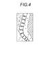
次いで、解析点設定部23が、後述するコントラストを算出するための解析点を、前処理が施された放射線画像G0に設定する(ステップST3)。具体的には、低周波成分L3′を用いて解析点を設定する。以下、解析点の設定について説明する。解析点設定部23は、放射線画像G0に含まれるスキンラインや照射野枠の影響を除外して、体動を検出する対象を放射線画像G0に含まれる骨部を含む被写体領域に限定すべく、放射線画像G0から被写体領域を抽出する。具体的には、対象となる被写体についての学習結果を用いる手法、被写体についてのルールベースの手法、グラフカット法等の各種セグメンテーション技術を用いて、放射線画像G0から被写体領域を抽出する。ここで、解析点は、体動の有無を判定しやすい部分、具体的には、骨部のエッジ上に解析点を抽出することが好ましい。このため、解析点設定部23は、多重解像度変換部22が生成した低周波成分L3′における被写体領域A0から比較的高い画素値となる画素を解析点として設定する。このようにして設定した解析点の例を図4に示す。
次いで、コントラスト算出部24が、解析点における高周波成分のコントラストおよび低周波成分のコントラストを算出する(ステップST4)。ここで、被写体に放射線を照射するわずかな時間(数十ミリ秒~数百ミリ秒)においては、体動は一方向のブレとして現れる。体動が発生した場合、放射線画像G0は体動の方向と同一方向に劣化するが、体動の方向に対して垂直な方向には劣化しない。このため、コントラスト算出部24は、まず各解析点におけるエッジの勾配方向を算出する。具体的には、コントラスト算出部24は、低周波成分L3′上に、図5に示すように、解析点P0を中心とする8つの方向を設定する。例えば、紙面の下から上に向かう方向を基準(0度)とした場合、-67.5度、-45度、-22.5度、0度、22.5度、45度、67.5度および90度の8つの方向を設定する。なお、8つの方向をそれぞれθ1~θ8とする。設定する方向は8に限定されるものではなく、2方向、4方向あるいは16方向等、任意の数とすることができる。
各方向毎に、解析点P0を中心とする特定サイズの解析領域を設定する。解析領域は、例えば9×9画素の矩形の領域である。解析領域内に複数のラインを仮想的に設定し、各ラインにおける画素値の最大値と最小値との差分値を各ラインにおけるコントラストとして算出する。ここで、ラインの方向は、その解析領域を設定した方向と一致させる。例えば、図5に示す方向θ1に解析領域を設定した場合、その解析領域に設定するラインの方向はθ1となる。
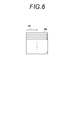
図6は解析領域および水平方向のラインを説明するための図である。図6に示すように解析点P0のある方向θ1に設定した解析領域A2に複数のラインが設定される。なお、ライン数は、解析領域A2の垂直方向の画素数と同一とすればよい。すなわち、解析領域A2のサイズが9×9画素であれば、ライン数は9とすればよい。ライン数は、適宜間引いて少なくしてもよい。
そして、コントラスト算出部24は、すべてのラインについてのコントラストの平均値を、低周波成分L3′においてその解析領域を設定した方向についてのコントラストとして算出する。そして、コントラスト算出部24は、8つの方向θ1~θ8のすべてに設定した解析領域のそれぞれについて、コントラストの平均値を各解析領域についてのコントラストCLθi(i=1~8)として算出する。さらに、コントラスト算出部24は、算出した8つのコントラストCLθiのうち、最も値が高いコントラストを算出した解析領域を設定した方向を、その解析点についてのエッジの勾配方向に決定する。
コントラスト算出部24は、高周波成分L0についても、低周波成分L3′と同様に、すべての解析点において、8つの方向θ1~θ8のすべてについての8つのコントラストCHθi(i=1~8)を算出する。そして、算出した8つのコントラストCHθiのうち、最も値が高いコントラストを算出した解析領域を設定した方向を、その解析点についてのエッジの勾配方向に決定する。
なお、各解析点において、コントラストが変化する方向は低周波成分L3′であっても高周波成分L0であっても同一となることから、各解析点におけるエッジの勾配方向は一致することとなる。このため、各解析点において同一のエッジ勾配方向についての、それぞれ1つの高周波成分のコントラストCHθiおよび低周波成分のコントラストCLθiが算出される。
撮影中に体動が生じた場合、取得される放射線画像G0においては、高周波成分のコントラストは低下するが、低周波成分のコントラストは殆ど低下しない。また、撮影条件あるいは被写体の種類によって、放射線画像全体のコントラストは変動するが、その変動は低周波成分のコントラストの差として現れる。したがって、高周波成分のコントラストと低周波成分のコントラストとの比率は、体動の程度を表す指標値として用いることができる。
このため、指標値算出部25は、各解析点における高周波成分のコントラストCHθiおよび低周波成分のコントラストCLθiの比率、より具体的には、低周波成分のコントラストCLθiに対する高周波成分のコントラストCHθiの比率CRθi(CRθi=CHθi/CLθi)を算出する(ステップST5)。さらに、指標値算出部25は、方向θi毎に、比率CRθiの平均値CRmθiを算出し、最も低い平均値CRmθiを体動の程度を表す指標値として算出する(ステップST6)。
なお、体動の程度を表す指標値の算出は上記手法に限定されるものではなく、各解析点における8つの方向のすべてについての高周波成分のコントラストCHθiおよび低周波成分のコントラストCLθiの比率CRθiを算出し、方向θi毎にすべての解析点についての高周波成分のコントラストCHθiおよび低周波成分のコントラストCLθiの比率CRθiの平均値CRmθiを算出し、この平均値のうちで最も低い平均値CRmLを体動の程度を表す指標値として算出してもよい。
表示制御部26は、複数の解析点における指標値に基づく複数の体動情報の少なくとも1つを、表示部40に選択的に表示する。以下、体動情報の選択的な表示について説明する。
上述したように、撮影中に体動が生じた場合、取得される放射線画像G0においては、高周波成分のコントラストは低下するが、低周波成分のコントラストは殆ど低下しない。このため、体動が生じなかった場合、指標値は1に近い値となるが、体動が生じた場合、指標値は1より小さく、かつ体動が大きいほど小さい値となる。このため、表示制御部26は、まず各解析点における指標値をしきい値Th1と比較し、複数の解析点のうち、指標値がしきい値Th1未満となる解析点を抽出する(ステップST7)。なお、しきい値Th1は1よりも小さいあらかじめ定められた値とする。
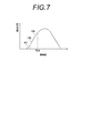
表示制御部26は、抽出した解析点について、さらにその指標値の大きさを複数段階に分類する(ステップST8)。本実施形態においては3段階に分類するものとするが、分類数はこれに限定されるものではない。図7は横軸に指標値を、縦軸に解析点の数をプロットしたヒストグラムを示す図である。表示制御部26は、図7に示すように、ヒストグラムにおいて、指標値がしきい値Th1未満となった部分をさらに3つの領域H1~H3に分類する。ここで、領域H1~H3においては、指標値が小さい領域ほど体動が大きいものとなっている。このため、表示制御部26は、放射線画像G0を表示部40に表示する際に、各領域H1~H3に分類される解析点に対して、指標値の大きさに応じて色が異なるマークを体動情報として表示する。例えば、指標値が小さい順、すなわち体動が大きい順に、赤、青、白のマークを表示する。
さらに表示制御部26は、各解析点において体動の方向および大きさ(すなわち指標値の大きさ)を確認し、隣接する解析点間において、体動の方向および大きさが同一となる解析点をグループ化する(ステップST9)。図8はグループ化の結果を示す図である。なお、図8においては、複数の解析点は3つのグループGr1~Gr3にグループ化されたものとする。
そして表示制御部26は、各グループGr1~Gr3を代表する代表解析点を決定する(ステップST10)。なお、グループGr2は非常に多くの解析点を含むため、適宜複数のグループ(ここでは2つのグループGr2-1,Gr2-2)に分割し、各グループGr2-1,Gr2-2において1つの代表解析点を決定するものとする。なお、代表解析点は、例えば各グループGr1~Gr3における最も中心に位置する解析点とすればよい。
そして、表示制御部26は、放射線画像G0上の各グループGr1~Gr3の代表解析点の位置にマーク(すなわち体動情報)を表示し(ステップST11)、処理を終了する。図9はマークを表示した放射線画像G0を示す図である。なお、表示部0に表示されるのは、放射線画像G0における被写体領域A0であるが、以下の説明においては、放射線画像G0が表示されるものとして説明する。図9に示すように、各グループGr1,Gr2-1,Gr2-2,Gr3の代表解析点に、それぞれ色が異なる三角形のマークM1~M4が表示されている。ここで、図9においては、色が異なることを三角形の塗りつぶしの態様を変更することにより表している。なお、色に代えて指標値の大きさに応じてマークの形状を変更するようにしてもよく、色とともにマークの形状を変更してもよい。
このように、第1の実施形態においては、指標値に基づく複数の体動情報のうちの少なくとも1つを表示部40に選択的に表示するようにしたため、複数の解析点についてのすべての体動情報が表示されることが無くなり、その結果、体動の有無の確認作業を効率よく行うことができる。
また、体動情報を指標値の大きさに応じて色が異なるマークとしているため、色の違いに基づいて体動があることにより観察に注意すべき部分の選別が容易となる。
また、しきい値Th1未満となる指標値となる解析点についての体動情報を表示するようにしたため、体動があり、観察に注意すべき部分を特定しやすくすることができる。
なお、上記第1の実施形態においては、体動の方向および大きさが同一となる解析点をグループ化し、各グループの代表解析点の位置に体動情報を表示しているが、隣接する解析点間の距離と体動の方向および大きさの類似度とに基づいて、代表解析点を決定するようにしてもよい。例えば、ある解析点と、その解析点と最も近い距離にある別の解析点とについて、体動の方向と大きさが所定の類似度以上である場合には、その2つの解析点は同一グループに属するものとして、いずれか一方の解析点を残し、他方の解析点を削除する。これをすべての解析点を対象として繰り返し行い、最終的に残った解析点を体動の方向および大きさが類似する解析点のグループの代表解析点に決定し、その代表解析点の位置に体動の方向および大きさを表示するようにしてもよい。
なお、上記第1の実施形態においては、マークに代えて、図10に示すように、体動の大きさおよび向きに応じたベクトルを体動情報として放射線画像G0に表示するようにしてもよい。図10においては、指標値の大きさに応じてベクトルの大きさを異なるものとしているが、体動の大きさに応じてベクトルの太さ、線種および色の少なくとも1つを変更するようにしてもよい。これにより、体動の原因を推測しやすくすることができ、その結果、再撮影を行う際に、体動が生じた部分を固定する等の対策をとりやすくすることができる。
表示部40の表示特性、具体的には表示部40の解像度、表示輝度、表示範囲等に応じて、放射線画像G0を確認するのに最適な、体動情報の表示個数が存在する。例えば、表示部40の解像度が低い場合、体動情報を多く表示すると、却って体動の確認がしにくくなってしまう。このため、表示部40の表示特性に応じた数の体動情報を表示することにより、体動の確認をより容易に行うことができる。
上記第1の実施形態においては、体動情報として指標値の大きさを表すマーク等を表示しているが、解析点を中心とする領域を拡大した拡大画像を体動情報として表示するようにしてもよい。以下、これを第2の実施形態として説明する。
拡大画像を表示する解析点は、上記第1の実施形態と同様に決定する。すなわち、体動が同一方向となる解析点をグループ化し、各グループを代表する代表解析点を決定する。そして、代表解析点を中心とするあるサイズの領域を放射線画像G0上に設定し、各領域の拡大画像を放射線画像G0に並べて表示する。図11は第2の実施形態における体動情報の表示を説明するための図である。図11に示すように、4つの解析点に対して各解析点を中心とする矩形の領域A11~A14を設定する。そして、放射線画像G0に並べて、各領域A11~A14の拡大画像を体動情報として表示する。ここで、拡大画像のサイズとしては、表示部40における画面サイズの1/4~1/2程度することが好ましい。また、複数の拡大画像を並べて表示するのみならず、複数の拡大画像を順次切り替え可能に表示するようにしてもよい。
なお、第2の実施形態のように拡大画像を体動情報として表示する場合、表示される被写体Hの部位に応じて、体動の確認に適した拡大画像の表示範囲および拡大率は異なる。このため、表示部40の表示特性に応じて拡大画像の表示範囲および拡大率の少なくとも一方を変更するようにしてもよい。これにより、拡大画像を用いての体動の確認をより容易に行うことができる。例えば、観察する部位が被写体Hの骨である場合、エッジの認識しやすさがより重要となる。このため、骨を観察する場合、軟部組織などを観察する場合よりも大きく表示することで、この骨の体動が確認しやすくなる。
また、表示部40の表示特性に応じて、体動の確認に適した拡大画像の表示範囲および拡大率は異なる。このため、表示部40の表示特性に応じて拡大画像の表示範囲および拡大率の少なくとも一方を変更するようにしてもよい。これにより、拡大画像を用いての体動の確認をより容易に行うことができる。
熟練した放射線技師であれば、拡大画像を見れば体動の有無を判定することは比較的容易であるが、経験が浅い技師は体動の有無を判定することが困難な場合が多い。このため、体動の有無を判定するための参照画像と体動情報とを並べて表示するようにしてもよい。具体的には、放射線画像撮影システムと接続されたあるいはシステム内に設けられたデータベースに、体動の有無を確認した放射線画像G0およびその放射線画像G0についての指標値を保存しておく。体動の有無の確認の対象となる放射線画像G0について、同一部位の過去に撮影された放射線画像のうち、対象となる放射線画像G0について算出した指標値と比較的近い指標値となる放射線画像を参照画像とする。この参照画像を、第2の実施形態のように拡大画像を体動情報として表示するのに際し、対象となる放射線画像G0と並べて表示部40に表示する。図12は放射線画像G0およびその拡大画像と参照画像とを並べて表示した状態を示す図である。図12に示すように参照画像R0を放射線画像G0および拡大画像と並べて表示することにより、拡大画像に体動が含まれているか否かの確認を、参照画像R0を用いて容易に行うことができるため、体動の有無の確認作業をより効率よく行うことができる。
参照画像R0としては、対象となる放射線画像G0について算出した指標値と比較的近い指標値となるもののみならず、体動がないと判定された放射線画像を参照画像R0として用いてもよい。この場合においても、参照画像R0を参照することにより、拡大画像に体動が含まれているか否かの確認を容易に行うことができるため、体動の有無の確認作業をより効率よく行うことができる。
上記第1の実施形態においては、体動情報として指標値の大きさを表すマーク等を表示し、第2の実施形態においては体動情報として拡大画像を表示しているが、指標値の大きさを表すマーク等および拡大画像の双方を体動情報として表示するようにしてもよい。以下、これを第3の実施形態とする。図13はマークおよび拡大画像の双方を表示した状態を示す図である。図13に示すように、第3の実施形態においては、放射線画像G0に第1の実施形態と同様にマークM1~M4が表示されており、かつマークM1~M4を付与した解析点を中心とするある領域A11~A14の拡大画像が放射線画像G0と並んで表示されている。これにより、体動の有無の確認をより容易に行うことができる。
上記第1から第3の実施形態において、体動の有無を確認した後、「体動があり」と判定される場合には、被写体Hを再撮影する必要がある。再撮影する場合、体動の程度に応じて再撮影時の撮影条件を変更することが好ましい。例えば、体動が発生した場合、再撮影時に放射線の照射時間を短く設定することにより、体動の影響を低減させることができる。例えば、最初の撮影時において、管電流が100mA、放射線の照射時間が150msecの撮影条件で体動が発生した場合、再撮影時においては、管電流を300mA、照射時間を50msecの撮影条件のように、照射時間を短くした撮影条件が設定されるようにしておく。これにより、再撮影時に、体動の影響を低減することができる。
体動の有無を確認した後、「体動があり」と判定される場合には、その体動が生じた箇所が使用者に認識される。このため、その体動が生じた箇所を固定する等して、体動が発生しないようにした後に、再撮影を行うようにしてもよい。
上記第1から第3の実施形態においては、しきい値Th1未満となる指標値となった解析点のみにおいて選択的に体動情報を表示しているが、すべての解析点を対象として、選択的に体動情報を表示するようにしてもよい。
上記第1から第3の実施形態においては、解析点設定部23において体動の有無を判定するための複数の解析点を設定しているが、放射線画像G0を表示部40に表示し、使用者がマニュアル操作にて複数の解析点を設定するようにしてもよい。また、解析点を放射線画像G0上における固定の場所としてもよい。この場合においても、複数の解析点における複数の体動情報を選択的に表示することにより、体動の有無の確認作業を容易に行うことができる。
上記第1から第3の実施形態においては、各解析点における高周波成分のコントラストCHθiおよび低周波成分のコントラストCLθiの比率に基づく指標値を算出しているが、体動の有無を確認可能な指標値であればこれに限定されるものではなく、公知の種々の指標値を用いることができる。例えば、上記特許文献1に記載された手法を用いて関心領域における体動の確率を算出し、算出した確率を指標値として用いるようにしてもよい。この場合、指標値が大きいほど体動が大きいこととなる。
上記第1から第3の実施形態においては、放射線画像G0において複数の解析点から、選択的に4つの解析点における体動情報を表示しているが、体動情報を表示する解析点の数はこれに限定されるものではなく、任意の数の解析点における体動情報を表示するようにしてもよい。なお、表示する体動情報の数としては5から20程度が好ましいが、上述したように表示部40の表示特性に応じて、この数を適宜増減することが好ましい。
上記第1から第3の実施形態においては、複数の解析点を設定して体動の程度を表す指標値を算出しているが、解析点に代えて放射線画像G0に複数の領域を設定し、領域毎に体動の程度を表す指標値を算出するようにしてもよい。
上記第1から第3の実施形態においては、多重解像度変換部22において放射線画像G0を多重解像度変換して、放射線画像G0の高周波成分および低周波成分を取得しているが、解析点を含む所定範囲の領域の放射線画像G0をフーリエ変換して、解析点についてのパワースペクトルを求め、パワースペクトルにおけるあらかじめ定められた高周波数帯域の値および低周波数帯域の値を、解析点における高周波成分のコントラストおよび低周波成分のコントラストとして算出してもよい。この場合、高周波成分のコントラストと低周波成分のコントラストとの比率は、実質的には、パワースペクトルにおける高周波成分と低周波成分との比率となる。
上記第1から第3の実施形態においては、放射線検出器11を用いて被写体の放射線画像を撮影する撮影装置10において取得した放射線画像を用いて体動を判定しているが、特開平8-266529号公報、特開平9-24039号公報等に示される放射線検出体としての蓄積性蛍光体シートに被写体の放射線画像情報を蓄積記録し、蓄積性蛍光体シートから光電的に読み取ることにより取得した放射線画像を用いて体動を判定するのに際しても、本発明を適用できる。
上述したように、放射線画像およびその指標値をデータベースに保存しておく場合、データベースを参照することにより、被写体Hの撮影部位に応じて体動がどの程度発生するかを確認することが可能となる。このため、撮影時においてデータベースを参照して、撮影部位が体動が発生しやすい部位であるか否かを確認し、体動が発生しやすい部位を撮影する場合には、体動が発生し易い部位を固定したり、放射線の照射時間を短くしたりして、体動を発生しにくくすることが可能となる。
以下、本発明の好ましい態様の作用効果について説明する。
体動情報が指標値の大きさを表す情報である場合、体動情報のうちの少なくとも1つを放射線画像に選択的に重畳して表示することにより、体動の大きさの確認を効率よく行うことができる。
体動情報を指標値の大きさに応じて色が異なるマークとすることにより、色の違いに基づいて、体動があることから観察に注意すべき部分の選別が容易となる。
体動情報を指標値の大きさおよび向きに応じたベクトルとすることにより、体動の原因を推測しやすくすることができ、その結果、再撮影を行う際に、体動がある部分を固定する等の対策をとりやすくすることができる。
特定の値以上の指標値となる部分についての体動情報を表示することにより、体動があることから観察に注意すべき部分を特定しやすくすることができる。
表示手段の表示特性、具体的には解像度、表示輝度、表示範囲等に応じて、画像を確認するのに最適な、体動情報の表示個数が存在する。例えば、解像度が低い表示手段では、体動情報を多く表示すると、却って体動の確認がしにくくなってしまう。このため、表示手段の表示特性に応じた数の体動情報を表示することにより、体動の確認をより容易に行うことができる。
体動情報が複数の部分の拡大画像である場合、体動情報のうちの少なくとも1つを選択的に表示することにより、体動の大きさの確認を効率よく行うことができる。
被写体の部位に応じて、体動の確認に適した拡大画像の表示範囲および拡大率は異なる。このため、表示手段の表示特性に応じて拡大画像の表示範囲および拡大率の少なくとも一方を変更することにより、体動の確認をより容易に行うことができる。
表示手段の表示特性、具体的には解像度、表示輝度、表示範囲等に応じて、体動の確認に適した拡大画像の表示範囲および拡大率は異なる。このため、表示手段の表示特性に応じて拡大画像の表示範囲および拡大率の少なくとも一方を変更することにより、体動の確認をより容易に行うことができる。
体動を含む参照画像を体動情報とともに表示することにより、拡大画像に体動が含まれているか否かの確認を、参照画像を用いて容易に行うことができるため、体動の有無の確認作業をより効率よく行うことができる。
10 撮影装置
11 放射線検出器
12 放射線管球
13 撮影制御部
14 撮影台
20 信号処理部
21 前処理部
22 多重解像度変換部
23 解析点設定部
24 コントラスト算出部
25 指標値算出部
26 表示制御部
30 入力部
40 表示部
11 放射線検出器
12 放射線管球
13 撮影制御部
14 撮影台
20 信号処理部
21 前処理部
22 多重解像度変換部
23 解析点設定部
24 コントラスト算出部
25 指標値算出部
26 表示制御部
30 入力部
40 表示部
Claims (11)
- 放射線画像上の複数の部分において、該放射線画像に含まれる被写体の体動の程度を表す指標値を算出する指標値算出手段と、
前記複数の部分における指標値に基づく複数の体動情報のうちの少なくとも1つを、選択的に表示手段に表示する表示制御手段とを備えたことを特徴とする体動表示装置。 - 前記体動情報が前記指標値の大きさを表す情報である場合、前記表示制御手段は、前記体動情報のうちの少なくとも1つを、前記放射線画像に選択的に重畳して前記表示手段に表示する請求項1記載の体動表示装置。
- 前記体動情報は、前記指標値の大きさに応じて色および形状の少なくとも一方が異なるマークである請求項2記載の体動表示装置。
- 前記体動情報は、前記指標値の大きさおよび向きに応じたベクトルである請求項2記載の体動表示装置。
- 前記表示制御手段は、前記表示手段の表示特性に応じた数の前記体動情報を前記表示手段に表示する請求項2から4のいずれか1項記載の体動表示装置。
- 前記体動情報は、前記複数の部分の拡大画像を含む請求項1から5のいずれか1項記載の体動表示装置。
- 前記表示制御手段は、前記被写体の部位に応じて、前記拡大画像の表示範囲および該拡大画像の拡大率の少なくとも一方を変更する請求項6記載の体動表示装置。
- 前記表示制御手段は、前記表示手段の表示特性に応じて、前記拡大画像の表示範囲および該拡大画像の拡大率の少なくとも一方を変更する手段であることを特徴とする請求項6記載の体動表示装置。
- 前記表示制御手段は、前記体動の有無の判断に参照される参照画像を前記体動情報とともに表示手段に表示する請求項6から8のいずれか1項記載の体動表示装置。
- 前記表示制御手段は、特定の値となる指標値を算出した部分についての前記体動情報を表示手段に表示する請求項1から9のいずれか1項記載の体動表示装置。
- 放射線画像上の複数の部分において、該放射線画像に含まれる被写体の体動の程度を表す指標値を算出し、
前記複数の部分における指標値に基づく複数の体動情報のうちの少なくとも1つを、表示手段に選択的に表示することを特徴とする体動表示方法。
Priority Applications (1)
| Application Number | Priority Date | Filing Date | Title |
|---|---|---|---|
| US14/807,666 US10194880B2 (en) | 2013-03-06 | 2015-07-23 | Body motion display device and body motion display method |
Applications Claiming Priority (2)
| Application Number | Priority Date | Filing Date | Title |
|---|---|---|---|
| JP2013-043671 | 2013-03-06 | ||
| JP2013043671A JP5992848B2 (ja) | 2013-03-06 | 2013-03-06 | 体動表示装置および方法 |
Related Child Applications (1)
| Application Number | Title | Priority Date | Filing Date |
|---|---|---|---|
| US14/807,666 Continuation US10194880B2 (en) | 2013-03-06 | 2015-07-23 | Body motion display device and body motion display method |
Publications (1)
| Publication Number | Publication Date |
|---|---|
| WO2014136641A1 true WO2014136641A1 (ja) | 2014-09-12 |
Family
ID=51491160
Family Applications (1)
| Application Number | Title | Priority Date | Filing Date |
|---|---|---|---|
| PCT/JP2014/054787 Ceased WO2014136641A1 (ja) | 2013-03-06 | 2014-02-27 | 体動表示装置および体動表示方法 |
Country Status (3)
| Country | Link |
|---|---|
| US (1) | US10194880B2 (ja) |
| JP (1) | JP5992848B2 (ja) |
| WO (1) | WO2014136641A1 (ja) |
Families Citing this family (3)
| Publication number | Priority date | Publication date | Assignee | Title |
|---|---|---|---|---|
| JP6789620B2 (ja) * | 2015-10-08 | 2020-11-25 | キヤノン株式会社 | 画像処理装置及びその制御方法、コンピュータプログラム |
| JP7098341B2 (ja) * | 2018-01-30 | 2022-07-11 | キヤノン株式会社 | 制御装置、放射線撮影システム、制御方法及びプログラム |
| JP7468427B2 (ja) * | 2021-03-25 | 2024-04-16 | コニカミノルタ株式会社 | 画像表示装置、制御プログラム、画像表示方法及び画像表示システム |
Citations (6)
| Publication number | Priority date | Publication date | Assignee | Title |
|---|---|---|---|---|
| JPH09190534A (ja) * | 1996-01-11 | 1997-07-22 | Canon Inc | 画像処理装置 |
| JP2006000421A (ja) * | 2004-06-18 | 2006-01-05 | Toshiba Corp | 超音波血流イメージング装置 |
| JP2006034521A (ja) * | 2004-07-26 | 2006-02-09 | Konica Minolta Medical & Graphic Inc | 医用画像処理装置及び医用画像処理方法 |
| JP2006217939A (ja) * | 2005-02-08 | 2006-08-24 | Hitachi Medical Corp | 画像表示装置 |
| JP2012075862A (ja) * | 2010-09-08 | 2012-04-19 | Fujifilm Corp | 体動検出装置、方法およびプログラム |
| JP2013102850A (ja) * | 2011-11-11 | 2013-05-30 | Konica Minolta Medical & Graphic Inc | 医用画像撮影システム、医用画像処理装置及びプログラム |
Family Cites Families (9)
| Publication number | Priority date | Publication date | Assignee | Title |
|---|---|---|---|---|
| US7158610B2 (en) * | 2003-09-05 | 2007-01-02 | Varian Medical Systems Technologies, Inc. | Systems and methods for processing x-ray images |
| JP4539186B2 (ja) | 2004-06-17 | 2010-09-08 | コニカミノルタエムジー株式会社 | 医用画像撮影システム、情報処理装置 |
| US7899229B2 (en) | 2007-08-06 | 2011-03-01 | Hui Luo | Method for detecting anatomical motion blur in diagnostic images |
| WO2009079344A1 (en) * | 2007-12-14 | 2009-06-25 | The Cleveland Clinic Foundation | System and method to characterize cardiac function |
| JP5438002B2 (ja) * | 2008-06-03 | 2014-03-12 | 株式会社日立メディコ | 医用画像処理装置及び医用画像処理方法 |
| US8180130B2 (en) * | 2009-11-25 | 2012-05-15 | Imaging Sciences International Llc | Method for X-ray marker localization in 3D space in the presence of motion |
| JP2011247358A (ja) | 2010-05-27 | 2011-12-08 | Nsk Ltd | 組合せ玉軸受及び複列玉軸受 |
| EP2653105B1 (en) | 2010-09-08 | 2015-04-15 | FUJIFILM Corporation | Body motion detection device and method, as well as radiographic imaging apparatus and method |
| JP5323795B2 (ja) * | 2010-10-12 | 2013-10-23 | 富士フイルム株式会社 | 診断支援装置、診断支援プログラムおよび診断支援方法 |
-
2013
- 2013-03-06 JP JP2013043671A patent/JP5992848B2/ja active Active
-
2014
- 2014-02-27 WO PCT/JP2014/054787 patent/WO2014136641A1/ja not_active Ceased
-
2015
- 2015-07-23 US US14/807,666 patent/US10194880B2/en active Active
Patent Citations (6)
| Publication number | Priority date | Publication date | Assignee | Title |
|---|---|---|---|---|
| JPH09190534A (ja) * | 1996-01-11 | 1997-07-22 | Canon Inc | 画像処理装置 |
| JP2006000421A (ja) * | 2004-06-18 | 2006-01-05 | Toshiba Corp | 超音波血流イメージング装置 |
| JP2006034521A (ja) * | 2004-07-26 | 2006-02-09 | Konica Minolta Medical & Graphic Inc | 医用画像処理装置及び医用画像処理方法 |
| JP2006217939A (ja) * | 2005-02-08 | 2006-08-24 | Hitachi Medical Corp | 画像表示装置 |
| JP2012075862A (ja) * | 2010-09-08 | 2012-04-19 | Fujifilm Corp | 体動検出装置、方法およびプログラム |
| JP2013102850A (ja) * | 2011-11-11 | 2013-05-30 | Konica Minolta Medical & Graphic Inc | 医用画像撮影システム、医用画像処理装置及びプログラム |
Also Published As
| Publication number | Publication date |
|---|---|
| US10194880B2 (en) | 2019-02-05 |
| JP2014171487A (ja) | 2014-09-22 |
| US20150327828A1 (en) | 2015-11-19 |
| JP5992848B2 (ja) | 2016-09-14 |
Similar Documents
| Publication | Publication Date | Title |
|---|---|---|
| KR102560911B1 (ko) | 화상 처리 장치, 화상 처리 방법 및 저장 매체 | |
| CN111325739B (zh) | 肺部病灶检测的方法及装置,和图像检测模型的训练方法 | |
| US12182970B2 (en) | X-ray imaging restoration using deep learning algorithms | |
| CN102274038B (zh) | 放射线图像区域提取装置、放射线图像区域提取方法以及放射线摄影装置 | |
| CN113129343B (zh) | 用于x射线成像中的解剖结构/视图分类的方法和系统 | |
| US12159420B2 (en) | Methods and systems for image registration | |
| JP5839710B2 (ja) | 解析点設定装置および方法、並びに体動検出装置および方法 | |
| JP7418171B2 (ja) | 画像処理装置、放射線撮影システム、画像処理方法及びプログラム | |
| US20240404055A1 (en) | Medical imaging and analysis method | |
| US9595116B2 (en) | Body motion detection device and method | |
| JP6642048B2 (ja) | 医療画像表示システム、医療画像表示プログラム及び医療画像表示方法 | |
| CN117916778A (zh) | 使用图像修复的对机器学习模型的发现特异性训练 | |
| JP5992848B2 (ja) | 体動表示装置および方法 | |
| CN111462067B (zh) | 图像分割方法及装置 | |
| JP4938427B2 (ja) | 脳出血部位体積計算装置 | |
| JP6789620B2 (ja) | 画像処理装置及びその制御方法、コンピュータプログラム | |
| US12272052B2 (en) | Method and system for image normalisation | |
| JP4532868B2 (ja) | 放射線画像処理装置 | |
| US11551356B2 (en) | Object detection method, object detection system for 3D mammogram, and non-transitory computer-readable storage medium | |
| US20240362774A1 (en) | Medical image processing apparatus and method | |
| WO2024122340A1 (ja) | 画像処理装置、画像処理装置の作動方法、およびプログラム | |
| JP2007037906A (ja) | 異常陰影候補検出システム |
Legal Events
| Date | Code | Title | Description |
|---|---|---|---|
| 121 | Ep: the epo has been informed by wipo that ep was designated in this application |
Ref document number: 14760620 Country of ref document: EP Kind code of ref document: A1 |
|
| NENP | Non-entry into the national phase |
Ref country code: DE |
|
| 122 | Ep: pct application non-entry in european phase |
Ref document number: 14760620 Country of ref document: EP Kind code of ref document: A1 |