WO2014136208A1 - 照明光学系および投写型表示装置 - Google Patents
照明光学系および投写型表示装置 Download PDFInfo
- Publication number
- WO2014136208A1 WO2014136208A1 PCT/JP2013/056007 JP2013056007W WO2014136208A1 WO 2014136208 A1 WO2014136208 A1 WO 2014136208A1 JP 2013056007 W JP2013056007 W JP 2013056007W WO 2014136208 A1 WO2014136208 A1 WO 2014136208A1
- Authority
- WO
- WIPO (PCT)
- Prior art keywords
- light
- optical system
- phosphor
- illumination optical
- display device
- Prior art date
- Legal status (The legal status is an assumption and is not a legal conclusion. Google has not performed a legal analysis and makes no representation as to the accuracy of the status listed.)
- Ceased
Links
Images





Classifications
-
- G—PHYSICS
- G03—PHOTOGRAPHY; CINEMATOGRAPHY; ANALOGOUS TECHNIQUES USING WAVES OTHER THAN OPTICAL WAVES; ELECTROGRAPHY; HOLOGRAPHY
- G03B—APPARATUS OR ARRANGEMENTS FOR TAKING PHOTOGRAPHS OR FOR PROJECTING OR VIEWING THEM; APPARATUS OR ARRANGEMENTS EMPLOYING ANALOGOUS TECHNIQUES USING WAVES OTHER THAN OPTICAL WAVES; ACCESSORIES THEREFOR
- G03B33/00—Colour photography, other than mere exposure or projection of a colour film
- G03B33/08—Sequential recording or projection
-
- G—PHYSICS
- G03—PHOTOGRAPHY; CINEMATOGRAPHY; ANALOGOUS TECHNIQUES USING WAVES OTHER THAN OPTICAL WAVES; ELECTROGRAPHY; HOLOGRAPHY
- G03B—APPARATUS OR ARRANGEMENTS FOR TAKING PHOTOGRAPHS OR FOR PROJECTING OR VIEWING THEM; APPARATUS OR ARRANGEMENTS EMPLOYING ANALOGOUS TECHNIQUES USING WAVES OTHER THAN OPTICAL WAVES; ACCESSORIES THEREFOR
- G03B21/00—Projectors or projection-type viewers; Accessories therefor
- G03B21/14—Details
- G03B21/20—Lamp housings
- G03B21/2006—Lamp housings characterised by the light source
- G03B21/2033—LED or laser light sources
- G03B21/204—LED or laser light sources using secondary light emission, e.g. luminescence or fluorescence
-
- H—ELECTRICITY
- H04—ELECTRIC COMMUNICATION TECHNIQUE
- H04N—PICTORIAL COMMUNICATION, e.g. TELEVISION
- H04N9/00—Details of colour television systems
- H04N9/12—Picture reproducers
- H04N9/31—Projection devices for colour picture display, e.g. using electronic spatial light modulators [ESLM]
- H04N9/3141—Constructional details thereof
- H04N9/315—Modulator illumination systems
- H04N9/3158—Modulator illumination systems for controlling the spectrum
-
- H—ELECTRICITY
- H04—ELECTRIC COMMUNICATION TECHNIQUE
- H04N—PICTORIAL COMMUNICATION, e.g. TELEVISION
- H04N9/00—Details of colour television systems
- H04N9/12—Picture reproducers
- H04N9/31—Projection devices for colour picture display, e.g. using electronic spatial light modulators [ESLM]
- H04N9/3179—Video signal processing therefor
- H04N9/3182—Colour adjustment, e.g. white balance, shading or gamut
Definitions
- the present invention relates to an illumination optical system including a phosphor that emits fluorescence when irradiated with excitation light, and a projection display device including the illumination optical system.
- Patent Document 1 Japanese Unexamined Patent Publication No. 2009-277516 (hereinafter referred to as Patent Document 1) and Japanese Unexamined Patent Application Publication No. 2011-13313 (hereinafter referred to as Patent Document 2) disclose a projection display provided with such an illumination optical system. An apparatus is disclosed.
- the illumination optical systems described in Patent Document 1 and Patent Document 2 include a fluorescent wheel having a phosphor layer.
- the fluorescent wheel is rotatable around a rotation axis, and a phosphor layer is formed in an annular shape around the rotation axis.
- the light source device includes a light source that irradiates the phosphor layer of the fluorescent wheel with excitation light.
- the phosphor layer emits fluorescence when irradiated with excitation light from the light source device.
- the phosphor wheel is rotated around the rotation axis while the phosphor layer is irradiated with the excitation light.
- a plurality of phosphor layers 61, 62, 63 that emit fluorescence of different colors along the rotation direction R of the phosphor wheel 60 are formed on the substrate 2.
- the first phosphor layer 61 is a phosphor that emits red fluorescence
- the second phosphor layer 62 is a phosphor that emits green fluorescence
- the third phosphor layer 63 emits blue fluorescence. It is a phosphor that emits light.
- the plurality of phosphor layers 61, 62, 63 are provided side by side in the circumferential direction around the rotation axis 10.
- Excitation light from the light source is applied to a point 64 on the phosphor wheel 60.
- the locus 67 of the irradiation spot 64 is drawn on the plurality of phosphor layers 61, 62, 63. Thereby, the light from different fluorescent substance layers 61, 62, and 63 is emitted in order.
- the emission time of the fluorescence emitted from each phosphor layer is determined by the size of the region where each phosphor layer is formed. Therefore, the ratio of the emission time of the fluorescence emitted from one phosphor layer 61 and the emission time of the fluorescence emitted from the other phosphor layers 62 and 63 is constant and cannot be changed.
- a single phosphor layer 71 is provided on the circumference along the rotation direction R of the phosphor wheel 70. Excitation light from the light source is applied to a point 64 on the phosphor wheel 70. In order to suppress deterioration of excitation light due to heat generation, the phosphor layer 71 is irradiated with excitation light while rotating the phosphor wheel 70. Thereby, the locus 65 of the irradiation spot 64 is drawn on the single phosphor layer 71.
- the illumination optical system in one embodiment of the present invention has a color wheel and a plurality of light sources.
- the color wheel is a substrate that can rotate around a rotation axis, and a plurality of phosphors that are formed on one surface of the substrate in a substantially concentric annular shape around the rotation axis and emit fluorescence of different wavelengths when irradiated with excitation light. And a layer.
- the plurality of light sources are provided corresponding to the respective phosphor layers and irradiate each phosphor layer with excitation light.
- a projection display device provided with the illumination optical system described above is also included in the scope of the present invention.
- each phosphor layer is provided with a separate light source for irradiating excitation light, each phosphor layer is irradiated with excitation light simultaneously, or each phosphor layer is sequentially turned on. Can be irradiated with excitation light.
- a general-purpose illumination optical system capable of emitting a plurality of types of fluorescence at an arbitrary timing can be provided.
- FIG. 4 is a side view of the phosphor wheel shown in FIG. 3.
- It is a schematic diagram which shows the structure of the projection type display apparatus of a 1st Example.
- It is a schematic diagram which shows the structure of the projection type display apparatus of a 2nd Example.
- It is a schematic diagram which shows the structure of the transmissive
- An illumination optical system includes a color wheel having a plurality of phosphor layers and a plurality of light sources provided corresponding to the respective phosphor layers.
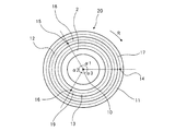
- FIG. 3 is a plan view of the color wheel.
- FIG. 4 is a side view of the color wheel.
- the color wheel 20 includes a substrate 2 that can rotate around the rotation axis 10. On one surface of the substrate 2, a first phosphor layer 11 that emits first fluorescence when irradiated with excitation light, a second phosphor layer 12 that emits second fluorescence when irradiated with excitation light, and an excitation light A third phosphor layer 13 that emits third fluorescence upon irradiation is provided.
- the color wheel 20 includes a drive motor 1 that rotates the substrate 2 provided with the phosphor layers 11 to 13 around the rotation axis 10.
- the first phosphor layer 11 is provided on one surface of the substrate 2 in an annular shape around the rotation axis 10.
- the second phosphor layer 12 is provided on one surface of the substrate 2 in an annular shape around the rotation axis 10.
- the third phosphor layer 13 is provided on one surface of the substrate 2 in an annular shape around the rotation axis 10. That is, the first phosphor layer 11, the second phosphor layer 12, and the third phosphor layer 13 are formed in a substantially concentric annular shape around the rotation axis 10.
- the first phosphor layer 11 is a phosphor that emits red light
- the second phosphor layer 12 is a phosphor that emits green light
- the third phosphor layer 13 is a fluorescence that emits blue light. It can be a body.
- the illumination optical system includes a first light source (see also reference numeral 21a shown in FIGS. 5 and 6) and a second light source (reference numeral 21b shown in FIGS. 5 and 6). Reference) and a third light source (not shown).
- the first light source 21 a is provided corresponding to the first phosphor layer 11 and irradiates the first phosphor layer 11 with excitation light.
- the second light source 21 b is provided corresponding to the first phosphor layer 12 and irradiates the second phosphor layer 12 with excitation light.
- the third light source is provided corresponding to the third phosphor layer 13 and irradiates the third phosphor layer 13 with excitation light.
- the first light source 21a, the second light source 21b, and the third light source may be laser light sources. All of these light sources may be light sources that emit blue-violet lasers. Further, the light source corresponding to the phosphor layer emitting blue light may be a light source emitting blue-violet laser, and the two light sources corresponding to the phosphor layers emitting red light and green light may be light sources emitting blue laser. It is not restricted to these examples, The wavelength of the light which each light source emits can be selected arbitrarily, and may mutually differ.
- FIG. 3 shows a position (irradiation spot) 14 on the first phosphor layer 11 to which the excitation light emitted from the first light source 21a is irradiated.
- FIG. 3 shows a position (irradiation spot) 15 on the second phosphor layer 12 to which the excitation light emitted from the second light source 21b is irradiated.
- FIG. 3 also shows a position (irradiation spot) 16 on the third phosphor layer 13 to which the excitation light emitted from the third light source is irradiated.
- a phosphor layer is formed on the right side of the substrate 2, and excitation light from each of the light sources 21 a and 21 b enters the phosphor layer from the right side of FIG. 4 toward the substrate 2. .
- the illumination optical system includes a control unit that controls driving of the driving motor 1 and light emission of the light sources 21a and 21b.
- the control unit freely controls the irradiation time of at least one of the plurality of light sources 21a and 21b, preferably all of the excitation light.
- the substrate 2 of the color wheel 20 is rotated in a predetermined direction R by the drive motor 1 while the excitation light emitted from each of the light sources 21a and 21b irradiates each phosphor layer 11, 12, and 13.
- the irradiation spots 14, 15, and 16 of the respective light sources draw traces 17, 18, and 19 along the annular phosphor layers 11, 12, and 13. Therefore, each irradiation spot 14, 15, 16 does not always irradiate the same portion of the phosphor layers 11, 12, 13, and the deterioration of the phosphor layers 11, 12, 13 due to heat generation can be suppressed.
- the illumination optical system described above since the individual light sources 21a and 21b for irradiating the respective phosphor layers 11, 12, and 13 with the excitation light are provided, the plurality of phosphor layers 11, 12, and 13 are simultaneously excited. It is possible to irradiate light, or to sequentially irradiate each phosphor layer 11, 12, 13 with excitation light. Thereby, a general-purpose illumination optical system capable of emitting a plurality of types of fluorescence at an arbitrary timing can be provided.
- an illumination optical system that emits light of three colors has been described.
- the present invention can be applied to an illumination optical system that emits light of two or more colors.
- the illumination optical system is provided corresponding to each of the plurality of phosphor layers formed in a substantially concentric annular shape around the rotation axis 10 and each phosphor layer. It is only necessary to have a plurality of light sources that emit excitation light.
- the color wheel only needs to include four types of phosphor layers and four light sources.
- the four types of phosphor layers may each be a phosphor that emits red light, a phosphor that emits blue light, a phosphor that emits green light, or a phosphor that emits yellow light.
- excitation light irradiation spots 14, 15, and 16 are provided on the respective phosphor layers 11, 12, and 13.
- the excitation spot on the phosphor layer 11 that emits red light is referred to as a first irradiation spot 14, and the excitation spot on the phosphor layer 12 that emits green light is referred to as a second irradiation spot 15.
- An excitation spot on the phosphor layer 13 that emits light is referred to as a third irradiation spot 15.
- the first irradiation spot 14, the second irradiation spot 15, and the third irradiation spot 16 are center angles ⁇ 1, ⁇ 2, which are substantially equal to each other with respect to the rotation direction R around the rotation axis 10. It is preferable that they are spaced apart by ⁇ 3.
- an angle formed by a straight line connecting the rotation axis 10 and the first irradiation spot 14 and a straight line connecting the rotation axis 10 and the second irradiation spot 15 is defined as ⁇ 1.
- An angle between a straight line connecting the rotation axis 10 and the second irradiation spot 15 and a straight line connecting the rotation axis 10 and the third irradiation spot 16 is defined as ⁇ 2.
- an angle formed by a straight line connecting the rotation axis 10 to the third irradiation spot 16 and a straight line connecting the rotation axis 10 to the first irradiation spot 14 is defined as ⁇ 3.
- the angles ⁇ 1, ⁇ 2, and ⁇ 3 are substantially the same angle, that is, substantially 120 °.
- the irradiation spots are preferably arranged apart from each other by substantially the same central angle.
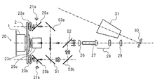
- FIG. 5 shows the configuration of the projection display apparatus in the first embodiment provided with the illumination optical system described above.
- the illumination optical system includes a color wheel 20 shown in FIGS. 3 and 4 and a motor 1 that rotationally drives the color wheel 20.
- a first phosphor layer 11, a second phosphor layer 12, and a third phosphor layer 13 are provided concentrically on one surface of the substrate 2 of the color wheel 20.
- the illumination optical system includes light sources 21a and 21b that irradiate the phosphor layers 11, 12, and 13 with excitation light. In FIG. 5, one of the three light sources is not shown because it is disposed behind the dichroic mirror 25c.
- the projection display device shown in FIG. 6 will be further described.
- the excitation light emitted from the first light source 21a is reflected by the dichroic mirror 25a and enters the first phosphor layer 11 emitting red light substantially perpendicularly.
- Red light is emitted from the first phosphor layer 11 by the irradiation of the excitation light.
- the red light is converted into substantially parallel light by the collimator lens group 23a and passes through the dichroic mirror 25a.
- the excitation light emitted from the second light source 21b is reflected by the dichroic mirror 25b and is incident substantially perpendicularly on the second phosphor layer 12 that emits green light. Green light is emitted from the second phosphor layer 12 by the irradiation of the excitation light. The green light is converted into substantially parallel light by the collimator lens group 23b and passes through the dichroic mirror 25b.
- Excitation light emitted from the third light source is reflected by the dichroic mirror 25c and is incident substantially vertically on the third phosphor layer 13 that emits blue light.
- Blue light is emitted from the third phosphor layer 13 by the irradiation of the excitation light. This blue light is converted into substantially parallel light by the collimator lens group 23c and passes through the dichroic mirror 25c.
- the red light passes through the dichroic mirror 25a and is then reflected by the reflection mirror 53a.
- the reflection surface of the reflection mirror 53a is perpendicular to the plane including the optical path of red light emitted from the first phosphor layer 11 and the optical path of green light emitted from the second phosphor layer 12, and is reflective.
- the angle may be set to be substantially 45 degrees.
- the red light reflected by the reflecting mirror 53 a is reflected by the first dichroic mirror 51.
- the green light emitted from the second phosphor layer 12 passes through the first dichroic mirror 51.
- the red light and the green light travel in the same direction after passing through the first dichroic mirror 51.
- the first dichroic mirror 51 spatially combines red light and green light.
- the reflection mirror 53a and the first dichroic mirror 51 are preferably arranged in parallel. That is, the incident angle of green light on the first dichroic mirror 51 is 45 degrees, and the incident angle of red light on the first dichroic mirror 51 is also 45 degrees.
- the first dichroic mirror 51 has a characteristic that reflects light having a longer wavelength than the red light emitted from the first phosphor layer and transmits light having a shorter wavelength than the red light. ing.
- the combined light obtained by combining the red light and the green light is incident on the reflection mirror 53b at an incident angle of substantially 45 degrees and proceeds toward the second dichroic mirror 52.
- the reflecting surface of the reflecting mirror 53b is perpendicular to the plane including the optical path of green light emitted from the second phosphor layer 12 and the optical path of blue light emitted from the third phosphor layer 13, and is reflective.
- the angle may be set to be substantially 45 degrees.
- the combined light of red light and green light reflected by the reflecting mirror 53 b is reflected by the second dichroic mirror 52.
- Blue light emitted from the third phosphor layer 13 passes through the second dichroic mirror 52.
- the combined light of red light and green light and blue light travel in the same direction after passing through the second dichroic mirror 52.
- the second dichroic mirror 52 spatially combines red light, green light, and blue light.
- the reflecting mirror 53b and the second dichroic mirror 52 are preferably arranged in parallel. That is, the incident angle of the combined light of the red light and the green light on the second dichroic mirror 52 is substantially 45 degrees, and the incident angle of the blue light on the second dichroic mirror 52 is also substantially 45 degrees. It is.
- the second dichroic mirror 52 reflects light having a wavelength longer than that of the green light emitted from the second phosphor layer 12 and transmits light having a wavelength shorter than that of the green light. Have.
- the illumination optical system includes a synthesis optical system that synthesizes the light emitted from the phosphor layers 11, 12, and 13.
- the synthesis optical system includes at least the first dichroic mirror 51 and the second dichroic.
- a mirror 52 is included.
- the three colors of light synthesized by the illumination optical system are incident on the lot lens 27 via the condenser lens 26.
- the lot lens 27 makes the illuminance distribution of the combined light uniform.
- the lot lens 27 may be a light tunnel configured by bonding four rectangular mirrors.
- the lot lens 27 converts the light distribution into a rectangle.
- the light passing through the rod lens 27 passes through the relay lens groups 28 and 29 and is irradiated onto the reflective image element (light valve) 30 while maintaining a substantially rectangular shape.
- the light applied to the reflective image element 30 is enlarged and projected on the screen via the projection lens 31.
- the image element 30 modulates incident light according to an image signal.
- a digital mirror device DMD
- DMD digital mirror device
- the DMD 30 is a semiconductor projection device including a large number of micromirrors arranged in a matrix. Each micromirror corresponds to a pixel of the projected image. Each micromirror is configured such that its mirror surface can be inclined at a predetermined angle, for example, ⁇ 12 degrees or ⁇ 10 degrees around the torsion axis.
- each micromirror By driving the electrode provided below each micromirror, each micromirror can be switched between an ON state (+12 degrees tilt) and an OFF state ( ⁇ 12 degrees).
- the light incident on the micro mirror in the ON state is reflected in the direction of the projection lens 31 and is enlarged and projected on the screen.
- the light incident on the micro mirror in the OFF state is reflected in a direction different from that of the projection lens 31 and is not projected on the screen.
- the ON state and the OFF state are switched at high speed, and the temporal ratio between the ON state and the OFF state is changed. Thereby, the gradation of each pixel can be expressed.
- the lot lens 27 is positioned on a straight line that passes through the third irradiation spot 16 of the third phosphor layer 13 that emits blue light having the shortest wavelength and is perpendicular to the substrate 2.
- the position of the rod lens 27 is not limited to this position, but a straight line passing through any one of the first irradiation spot 14, the second irradiation spot 15, and the third irradiation spot 16 among straight lines perpendicular to the substrate 2. It is preferable to be arranged on the top.
- the rod lens 27 is placed on a straight line passing through the phosphor layer that excites the light with the longest wavelength or the phosphor layer that excites the light with the shortest wavelength. It is more preferable.
- the light paths of the light of each color are synthesized, but the light of each color is emitted sequentially in time. In other words, red light, blue light, and green light are emitted in a time division manner.
- separate light sources for irradiating the phosphor layers 11, 12, and 13 with excitation light are used. Therefore, by controlling the light emission time of each light source, the fluorescence of each color is controlled. The lighting time can be freely controlled.
- the lighting time of each color light can be freely changed as long as the timing and timing of the DMD 30 micro mirror are matched. It is also possible to light two colors or three colors simultaneously.
- the ratio of the lighting time of the fluorescence emitted from each phosphor layer is determined by the size of the region where each phosphor layer is formed, and cannot be freely controlled. .
- the application area of the phosphor applied to the phosphor wheel 60 may vary individually. When variation occurs in the size of the application area of each phosphor, it is necessary to adjust the timing of synchronization with the DMD 30.
- the model of the projection display device when the model of the projection display device is changed, an improvement in which the light output of the light source is increased may be performed, but due to the characteristics of the phosphor applied to the phosphor wheel 60, the increase in the output of the excitation light can be prevented.
- the increase in the luminous output of the phosphor is not uniform. That is, the balance of the amount of fluorescent light of each color changes due to the change in the output of the light source. This also changes the color coordinates. As a result, it becomes necessary to adjust the size of the phosphor region applied to the color wheel.
- the projection type display apparatus of the said Example is equipped with the separate light source which irradiates each phosphor layer 11,12,13 with excitation light, it irradiates each phosphor layer 11,12,13. It is possible to freely adjust the irradiation time of the excitation light.
- a light source such as an LED or LD that emits light of a different color
- the LED light source has an effect that it is possible to realize adjustment of the mixed color and adjustment of the light amount of each color without changing the color wheel 20 in response to the model change caused by changing the light amount and color of the LD used without wavelength conversion. .
- the lighting time of each color light can be freely changed by using the common color wheel 20.
- the lighting time of each color light can be easily performed by the control unit of the illumination optical system controlling the light emission time of each light source 23a, 23b.
- FIG. 6 shows the configuration of the projection display device in the second embodiment provided with the illumination optical system described above.
- the mechanical configuration of the illumination optical system is the same as that shown in FIG.
- the illumination optical system synthesizes the light emitted from the phosphor layers 11, 12, and 13 as in the projection display device in the first embodiment. This combined light passes through the fly-eye lens group 33 and the field lenses 34 and 35.
- the combined light that has passed through the lens 35 is separated into light of each color by the dichroic mirror 36.
- the dichroic mirror 36 reflects red light and transmits green light and blue light.
- the red light reflected by the dichroic mirror 36 is reflected by the reflection mirror 40 and enters the first transmission type image element (light valve) 44a.
- the combined light of green light and blue light transmitted through the dichroic mirror 36 enters the dichroic mirror 37.
- the dichroic mirror 37 separates green light and blue light. Specifically, the green light is reflected by the dichroic mirror 37 and enters the second transmissive image element 44b.
- the blue light transmitted through the dichroic mirror 37 enters the third transmission type image element 44 c via the lens system 38 and the reflection mirror 39.
- These image elements 44a, 44b and 44c modulate incident light in accordance with the image signal.
- a liquid crystal panel can be used as the first to third transmissive image elements.
- FIG. 7 shows a configuration 41 around the liquid crystal panel shown in FIG.
- the projection display device according to the present embodiment corresponds to the light of each color and includes three liquid crystal panels 44a, 44b, and 44c.
- Polarizing plates 43a, 43b, 43c, 45a, 45b, and 45c are provided on both sides of each liquid crystal panel 44a, 44b, and 44c.
- the light of each color enters the condenser lenses 42a, 42b, and 42c before entering the liquid crystal panels 44a to 44c and the polarizing plates 43a to 43c and 45a to 45c.
- the first liquid crystal panel 44a changes the polarization state of red light for each pixel.
- the second liquid crystal panel 44b changes the polarization state of green light for each pixel.
- the third liquid crystal panel 44c changes the polarization state of blue light for each pixel.
- the light of each color can be projected as an image by the action of the liquid crystal panels 44a to 44c and the polarizing plates 43a to 43c and 45a to 45c.
- the light of each color that has passed through the liquid crystal panels 44a to 44c and the polarizing plates 43a to 43c and 45a to 45c is incident on the cross dichroic prism 46.
- the light of each color is synthesized by the cross dichroic prism 46 and then projected onto a screen or the like through the projection lens 31. In this way, a full color image is projected on a projection object such as a screen.
- the three colors of light are synthesized by the synthesis optical systems 51 and 52, and then separated into the respective colors by the separation optical systems 36 and 37.
- the light of each color may be incident on the corresponding liquid crystal panels 44a to 44c without being synthesized.
- the projected image or video can be brightened.
- each light source 21a, 21b irradiates each phosphor layer 11, 12, 13 simultaneously and continuously.
- the projection display device can be miniaturized.
- the projection type display device including the color wheel 20 having the three types of phosphor layers 11, 12, 13 has been described.
- the color wheel 20 may have two types of phosphor layers.
- the projection display device only needs to include another light source that emits light of another color, for example, a light emitting diode (LED).
- LED light emitting diode
- the luminous efficiency of the phosphor layer depends on the efficiency of the laser that is the excitation light. However, the luminous efficiency of the phosphor layer that emits green light is higher than that of the LED, and the phosphor layer that emits red light is about the same as the luminous efficiency of the LED. Therefore, the projection display device may be configured by a color wheel having a phosphor layer that emits green light and a phosphor layer that emits red light, and another light source that emits blue light. In this case, there is an advantage that a small and bright projection display device can be realized.
Landscapes
- Engineering & Computer Science (AREA)
- Multimedia (AREA)
- Physics & Mathematics (AREA)
- Signal Processing (AREA)
- General Physics & Mathematics (AREA)
- Optics & Photonics (AREA)
- Projection Apparatus (AREA)
Abstract
本発明の一目的は、複数種の蛍光を任意のタイミングで射出することができる汎用的な照明光学系を提供する。照明光学系は、カラーホイール(20)と、複数の光源と、を有する。カラーホイールは、回転軸まわりに回転可能な基板(2)と、基板の一面に回転軸を中心として実質的に同心の円環状に形成され、励起光の照射によりそれぞれ異なる波長の蛍光を発する複数の蛍光体層(11、12、13)と、を有する。複数の光源は、各々の蛍光体層に対応して設けられ、各々の蛍光体層に励起光を照射する。
Description
本発明は、励起光の照射により蛍光を発する蛍光体を備えた照明光学系および当該照明光学系を備えた投写型表示装置に関する。
近年、励起光を蛍光体に照射することによって蛍光体から発せられた光を利用した光源装置(照明光学系)の開発が行われている。特開2009-277516号公報(以下、特許文献1と称する。)および特開2011-13313号公報(以下、特許文献2と称する。)には、このような照明光学系を備えた投写型表示装置が開示されている。
特許文献1および特許文献2に記載の照明光学系は、蛍光体層を有する蛍光ホイールを備えている。蛍光ホイールは、回転軸を中心に回転可能となっており、回転軸を中心として環状に蛍光体層が形成されている。光源装置は、蛍光ホイールの蛍光体層に励起光を照射する光源を備えている。蛍光体層は、光源装置からの励起光の照射により蛍光を発する。励起光の照射による発熱によって蛍光体が劣化することを抑制するため、蛍光体層に励起光を照射する間、蛍光体ホイールは回転軸まわりに回転させられる。
照明光学系の用途に応じて、互いに異なる色の蛍光を時間的に順番に出射することが求められることがある。この場合、図1に示すように、蛍光体ホイール60の回転方向Rに沿って異なる色の蛍光を発する複数の蛍光体層61,62,63が基板2上に形成される。例えば、第1の蛍光体層61は赤色の蛍光を発する蛍光体であり、第2の蛍光体層62は緑色の蛍光を発する蛍光体であり、第3の蛍光体層63は青色の蛍光を発する蛍光体である。具体的には、複数の蛍光体層61,62,63は、回転軸10を中心として円周方向に並んで設けられる。
光源からの励起光は、蛍光体ホイール60上の一点64に照射される。励起光の照射とともに基板2を回転させることにより、照射スポット64の軌跡67が複数の蛍光体層61,62,63上に描かれる。これにより、異なる蛍光体層61,62,63からの光が順番に発せられる。
しかしながら、このような蛍光体ホイール60は、同一の蛍光体層から発せられた同一の光を継続して出射することができない。また、各蛍光体層から発せられる蛍光の出射時間は、各蛍光体層が形成されている領域の大きさによって決まってしまう。そのため、一の蛍光体層61から発せられる蛍光の出射時間と、他の蛍光体層62,63から発せられる蛍光の出射時間との比は一定になり、変更することができない。
また、照明光学系の用途に応じては、同一色の光を継続的に出射することが求められることがある。この場合、図2に示すように、蛍光体ホイール70の回転方向Rに沿って円周上に単一の蛍光体層71が設けられる。光源からの励起光は、蛍光体ホイール70上の一点64に照射される。発熱による励起光の劣化を抑制するため、蛍光体ホイール70を回転しつつ蛍光体層71に励起光を照射する。これにより、照射スポット64の軌跡65が単一の蛍光体層71上に描かれる。
しかしながら、このような蛍光体ホイールでは、互いに異なる色の蛍光を時間的に順番に出射することができない。互いに異なる色の蛍光を出射するためには、図2に示す構成の蛍光体ホイールを複数用意する必要があり、照明光学系が大型化してしまう。
このように、用途に応じて、異なる構成を有する蛍光体ホイールが使い分けられている。したがって、様々な用途で使用できる汎用的な蛍光体カラーホイールを備えた照明光学系が望まれる。
本発明の一実施形態における照明光学系は、カラーホイールと、複数の光源と、を有する。カラーホイールは、回転軸まわりに回転可能な基板と、基板の一面に回転軸を中心として実質的に同心の円環状に形成され、励起光の照射によりそれぞれ異なる波長の蛍光を発する複数の蛍光体層と、を有する。複数の光源は、各々の蛍光体層に対応して設けられ、各々の蛍光体層に励起光を照射する。
また、上記の照明光学系を備えた投射型表示装置も本発明の範囲に含まれる。
上記の照明光学系によれば、各蛍光体層に励起光を照射する別個の光源が設けられているため、各々の蛍光体層へ同時に励起光を照射したり、各々の蛍光体層へ順番に励起光を照射したりすることができる。これにより、複数種の蛍光を任意のタイミングで射出することができる汎用的な照明光学系を提供することができる。
次に、本発明の実施形態について、図面を参照して説明する。
本発明の一実施形態における照明光学系は、複数の蛍光体層を有するカラーホイールと、各々の蛍光体層に対応して設けられた複数の光源と、を備えている。図3は、カラーホイールの平面図である。図4は、カラーホイールの側面図である。
カラーホイール20は、回転軸10まわりに回転可能な基板2を備えている。基板2の一面には、励起光の照射により第1の蛍光を発する第1の蛍光体層11と、励起光の照射により第2の蛍光を発する第2の蛍光体層12と、励起光の照射により第3の蛍光を発する第3の蛍光体層13とが設けられている。カラーホイール20は、蛍光体層11~13が設けられた基板2を回転軸10周りに回転させる駆動モータ1を備えている。
第1の蛍光体層11は、基板2の一面に、回転軸10を中心として円環状に設けられている。第2の蛍光体層12は、基板2の一面に、回転軸10を中心として円環状に設けられている。第3の蛍光体層13は、基板2の一面に、回転軸10を中心として円環状に設けられている。つまり、第1の蛍光体層11、第2の蛍光体層12および第3の蛍光体層13は、回転軸10を中心にして、実質的に同心の円環状に形成されている。
一例として、第1の蛍光体層11は赤色に発光する蛍光体であり、第2の蛍光体層12は緑色に発光する蛍光体であり、第3の蛍光体層13は青色に発光する蛍光体であって良い。
照明光学系は、カラーホイール20の他に、第1の光源(図5および図6に示された符号21aも参照)と、第2の光源(図5および図6に示された符号21bも参照)と、第3の光源(不図示)と、を備えている。
第1の光源21aは、第1の蛍光体層11に対応して設けられ、第1の蛍光体層11に励起光を照射する。第2の光源21bは、第1の蛍光体層12に対応して設けられ、第2の蛍光体層12に励起光を照射する。第3の光源は、第3の蛍光体層13に対応して設けられ、第3の蛍光体層13に励起光を照射する。
第1の光源21a、第2の光源21bおよび第3の光源は、レーザ光源であって良い。これらの光源は全て青紫レーザを発する光源でも良い。また、青色光を発する蛍光体層に対応する光源が青紫レーザを発する光源で、赤色光および緑色光を発する蛍光体層に対応する2つの光源が青色レーザを発する光源であっても良い。これらの例に限られず、各々の光源が発する光の波長は、任意に選択することができ、互いに異なっていても良い。
図3には、第1の光源21aから出射された励起光が照射される、第1の蛍光体層11上の位置(照射スポット)14が示されている。図3には、第2の光源21bから出射された励起光が照射される、第2の蛍光体層12上の位置(照射スポット)15が示されている。また、図3には、第3の光源から出射された励起光が照射される、第3の蛍光体層13上の位置(照射スポット)16が示されている。なお、図4では、基板2の右側面に蛍光体層が形成されており、各光源21a,21bからの励起光は、図4の右側から基板2の方に向けて蛍光体層に入射する。
照明光学系は、駆動モータ1の駆動や光源21a,21bの発光等を制御する制御部を備えている。制御部は、複数の光源21a,21bのうちの少なくとも1つ、好ましくは全ての励起光の照射時間を自由に制御する。各光源21a,21bから照射された励起光が各蛍光体層11,12,13を照射している間、駆動モータ1によりカラーホイール20の基板2が所定の方向Rに回転する。これにより、各光源の照射スポット14,15,16が円環状の蛍光体層11,12,13に沿った軌跡17,18,19を描く。よって、各照射スポット14,15,16が蛍光体層11,12,13の同一箇所を常に照射しつづけることがなく、発熱による蛍光体層11,12,13の劣化を抑制することができる。
上記の照明光学系によれば、各蛍光体層11,12,13に励起光を照射する別個の光源21a,21bが設けられているため、複数の蛍光体層11,12,13へ同時に励起光を照射したり、各蛍光体層11,12,13へ順番に励起光を照射したりすることができる。これにより、複数種の蛍光を任意のタイミングで射出することができる汎用的な照明光学系を提供することができる。
上記実施形態では、3色の光を発する照明光学系について説明したが、本発明は、2色以上の光を発する照明光学系に適用できる。この場合、照明光学系は、回転軸10を中心として実質的に同心の円環状に形成された複数の蛍光体層と、各々の蛍光体層に対応して設けられ、各々の蛍光体層に励起光を照射する複数の光源と、を有していれば良い。
例えば、2色の光を発する照明光学系では、カラーホイールに設けられた蛍光体層は2種類で、光源も2つあればよい。
また、4色の光を発する照明光学系では、カラーホイールは、4種類の蛍光体層と、4つの光源とを備えていれば良い。この場合、4種類の蛍光体層は、それぞれ、赤色光を発する蛍光体、青色光を発する蛍光体、緑色光を発する蛍光体または黄色光を発する蛍光体であって良い。
図3において、励起光の照射スポット14,15,16はぞれぞれの蛍光体層11,12,13上に1箇所ずつある。本例では、赤色に発光する蛍光体層11への励起スポットを第1の照射スポット14と称し、緑色に発光する蛍光体層12への励起スポットを第2の照射スポット15と称し、青色に発光する蛍光体層13への励起スポットを第3の照射スポット15と称する。
第1の照射スポット14と、第2の照射スポット15と、第3の照射スポット16とは、回転軸10を中心とした回転方向Rに対して、実質的に互いに等しい中心角α1,α2,α3だけ離れて配置されていることが好ましい。
図3では、回転軸10から第1の照射スポット14を結ぶ直線と、回転軸10から第2の照射スポット15を結ぶ直線との成す角度をα1と定義している。回転軸10から第2の照射スポット15を結ぶ直線と、回転軸10から第3の照射スポット16を結ぶ直線との成す角度をα2と定義している。さらに、回転軸10から第3の照射スポット16を結ぶ直線と、回転軸10から第1の照射スポット14を結ぶ直線との成す角度をα3と定義している。このとき、角度α1,α2,α3は、実質的に同じ角度、すなわち実質的に120°となっている。
照明光学系が、任意の数の蛍光体層および照射スポットを有する場合であっても、当該照射スポットは、実質的に互いに等しい中心角だけ離れて配置されていることが好ましい。
図5は、上述した照明光学系を備えた第1の実施例における投写型表示装置の構成を示している。照明光学系は、図3および図4に示すカラーホイール20と、カラーホイール20を回転駆動するモータ1と、を有する。カラーホイール20の基板2の一面には、第1の蛍光体層11と第2の蛍光体層12と第3の蛍光体層13とが、同心円状に設けられている。また、照明光学系は、各々の蛍光体層11,12,13に励起光を照射する光源21a,21bを備えている。なお、図5では、3つの光源のうちの1つは、ダイクロイックミラー25cの背後に配置されているため、図示されていない。
図6に示す投射型表示装置についてさらに説明する。第1の光源21aから発せられた励起光は、ダイクロイックミラー25aで反射され、赤色に発光する第1の蛍光体層11に実質的に垂直に入射する。この励起光の照射によって第1の蛍光体層11から赤色の光が発せられる。この赤色光はコリメーターレンズ群23aで略平行光に変換され、ダイクロイックミラー25aを透過する。
第2の光源21bから発せられた励起光は、ダイクロイックミラー25bで反射され、緑色に発光する第2の蛍光体層12に実質的に垂直に入射する。この励起光の照射によって第2の蛍光体層12から緑色の光が発せられる。この緑色光はコリメーターレンズ群23bで略平行光に変換され、ダイクロイックミラー25bを透過する。
第3の光源から発せられた励起光は、ダイクロイックミラー25cで反射され、青色に発光する第3の蛍光体層13に実質的に垂直に入射する。この励起光の照射によって第3の蛍光体層13から青色の光が発せられる。この青色光はコリメーターレンズ群23cで略平行光に変換され、ダイクロイックミラー25cを透過する。
赤色光は、ダイクロイックミラー25aを透過した後、反射ミラー53aで反射される。反射ミラー53aの反射面は、第1の蛍光体層11から発せられた赤色光の光路と第2の蛍光体層12から発せられた緑色光の光路とを含む平面に垂直で、かつ、反射角が実質的に45度になるように設定されていて良い。
反射ミラー53aで反射された赤色光は、第1のダイクロイックミラー51によって反射される。第2の蛍光体層12から発せられた緑色光は、第1のダイクロイックミラー51を透過する。赤色光と緑色光は、第1のダイクロイックミラー51を通過した後、同一の方向へ向かう。言い換えると、第1のダイクロイックミラー51は、赤色光と緑色光とを空間的に合成する。
このとき、反射ミラー53aと第1のダイクロイックミラー51とは平行に配置されていることが好ましい。すなわち、第1のダイクロイックミラー51への緑色光の入射角は45度であり、第1のダイクロイックミラー51への赤色光の入射角も45度である。また、第1のダイクロイックミラー51は、第1の蛍光体層から発せられた赤色光よりも波長が長い光を反射し、該赤色光よりも波長が短い光が透過するような特性を有している。
赤色光と緑色光とが合成された合成光は、反射ミラー53bに実質的に45度の入射角で入射し、第2のダイクロイックミラー52に向かって進む。反射ミラー53bの反射面は、第2の蛍光体層12から発せられた緑色光の光路と第3の蛍光体層13から発せられた青色光の光路とを含む平面に垂直で、かつ、反射角が実質的に45度になるように設定されていて良い。
反射ミラー53bで反射された赤色光と緑色光との合成光は、第2のダイクロイックミラー52で反射する。第3の蛍光体層13から発せられた青色光は、第2のダイクロイックミラー52を透過する。赤色光と緑色光との合成光と、青色光とは、第2のダイクロイックミラー52を通過した後、同一の方向へ向かう。言い換えると、第2のダイクロイックミラー52は、赤色光と緑色光と青色光とを空間的に合成する。
反射ミラー53bと第2のダイクロイックミラー52とは平行に配置されていることが好ましい。すなわち、第2のダイクロイックミラー52への赤色光と緑色光との合成光の入射角は実質的に45度であり、第2のダイクロイックミラー52への青色光の入射角も実質的に45度である。ここで、第2のダイクロイックミラー52は、第2の蛍光体層12から発せられた緑色光よりも波長が長い光を反射し、該緑色光よりも波長が短い光が透過するような特性を有している。
以上のように、第1のダイクロイックミラー51と第2のダイクロイックミラー52とにより、赤色光、緑色光および青色光が合成される。換言すると、照明光学系は、蛍光体層11,12,13から発せられた光を合成する合成光学系を備えており、当該合成光学系は、少なくとも第1のダイクロイックミラー51と第2のダイクロイックミラー52を含んでいる。
照明光学系で合成された3色の光は、集光レンズ26を介してロットレンズ27に入射する。ロットレンズ27は、合成光の照度分布が均一にする。ロットレンズ27は長方形の4枚のミラーを張り合わせて構成されるライトトンネルであって良い。ロットレンズ27により光の分布が矩形に変換される。ロッドレンズ27を通った光は、リレーレンズ群28,29を通り、ほぼ矩形な形状を維持したまま反射型の画像素子(ライトバルブ)30上に照射する。反射型の画像素子30に照射した光は、投写レンズ31を介してスクリーン上に拡大投写される。画像素子30は、入射光を画像信号に合わせて変調する。反射型の画像素子30としては、例えばデジタルミラーデバイス(DMD)を用いることができる。
DMD30は、マトリックス状に配列された多数の微小ミラーを備えた半導体型投写デバイスである。各微小ミラーが、投射される画像の画素に対応する。各微小ミラーはその鏡面をねじれ軸周りに所定の角度、例えば±12度または±10度、傾斜することができるように構成されている。
各微小ミラーの下部に設けられた電極を駆動することにより、各微小ミラーを、ON状態(+12度傾斜)とOFF状態(-12度)とに切り替えることができる。ON状態の微小ミラーに入射した光は、投写レンズ31の方向に反射され、スクリーンに拡大投影される。OFF状態の微小ミラーに入射した光は、投写レンズ31とは異なる方向に反射され、スクリーンに投影されない。各微小ミラーにおいてON状態とOFF状態の切り替えを高速で行い、ON状態とOFF状態の時間的な比率を変化させる。これにより、各画素の階調を表現することができる。
上記実施例において、ロットレンズ27は、一番波長が短い青色光を発する第3の蛍光体層13の第3の照射スポット16を通り基板2に垂直な直線上に位置している。ロッドレンズ27の位置は、この位置に限られないが、基板2に垂直な直線のうち、第1の照射スポット14、第2の照射スポット15または第3の照射スポット16のいずれかを通る直線上に配置されていることが好ましい。ただし、ダイクロイックミラー51,52による光合成を考慮すると、ロッドレンズ27は、一番波長が長い光を励起する蛍光体層若しくは一番波長が短い光を励起する蛍光体層を通る直線上に置かれているがより好ましい。
本実施例の投射型表示装置では、各色の光の光路は合成されているが、各色の光は時間的に順番に発せられる。言い換えると、赤色光と青色光と緑色光は時分割的に発せられる。本実施例の投射型表示装置では、各蛍光体層11,12,13に励起光を照射するための別個の光源が用いられているため、各光源の発光時間の制御により、各色の蛍光の点灯時間を自由に制御することができる。
各色の光の点灯時間は、DMD30の微小ミラーの制御とタイミングを合わせてさえいれば、自由に変更可能である。また、2色或いは3色の光を同時に点灯することも可能となる。
これに対し、図1に示す蛍光体ホイール60を用いて、各色の光を時分割的に照射する投写型表示装置を構成することもできる。しかしながら、この場合、上述したように、各蛍光体層から発せられる蛍光の点灯時間の割合は、各蛍光体層が形成されている領域の大きさによって決まってしまい、自由に制御することはできない。
また、製造上の観点で、蛍光体ホイール60に塗布された蛍光体の塗布領域が個々にばらつきをもつことがある。各々の蛍光体の塗付領域の大きさにばらつきが生じた場合、DMD30との同期のタイミングを調整する必要がでてくる。
また、投写型表示装置のモデルチェンジの際に、光源の光出力を増加させる改善を行うことがあるが、蛍光体ホイール60に塗付された蛍光体の特性により、励起光の出力の増加に対する蛍光体の発光出力の増加は一律ではない。すなわち、光源の出力の変更により各色の蛍光の光量のバランスが変わってくる。これにより、色座標も変わる。その結果、カラーホイールに塗布する蛍光体の領域の大きさを調整する必要が生じてくる。
これに対し、上記実施例の投写型表示装置は、各蛍光体層11,12,13に励起光を照射する別個の光源を備えているため、各蛍光体層11,12,13に照射する励起光の照射時間を自由に調整することが可能となる。また、2種類の色の蛍光を出射するカラーホイール20のほかに別種の色の光を発するLEDやLDなどの光源を用いる場合、個々の光源のばらつきによる混合色の調整が自由に設定可能となり、製品個々の色のばらつきを抑える効果がある。LED光源は波長変換せずに使用するLDの光量や色が変わることによるモデルチェンジに対し、混合色の調整や、各色の光量の調整を、カラーホイール20を変更せずに実現できる効果がある。
このように、本発明のカラーホイール20を有する照明光学系を備えた投写型表示装置においては、共通のカラーホイール20を用いて、各色の光の点灯時間を自由に変更できるという利点がある。各色の光の点灯時間は、照明光学系の制御部が各光源23a,23bの発光時間を制御することにより容易に行うことができる。
図6は、上述した照明光学系を備えた第2の実施例における投写型表示装置の構成を示している。照明光学系の機械的構成は、図5に示したものと同様である。照明光学系は、第1の実施例における投写型表示装置と同様に、各蛍光体層11,12,13から発せられた光を合成する。この合成光は、フライアイレンズ群33、フィールドレンズ34,35を通過する。
レンズ35を通過した合成光は、ダイクロイックミラー36によって各色の光に分離される。具体的には、ダイクロイックミラー36は、赤色光を反射し、緑色光および青色光を透過する。ダイクロイックミラー36で反射した赤色光は、反射ミラー40で反射して第1の透過型の画像素子(ライトバルブ)44aに入射する。
ダイクロイックミラー36を透過した緑色光と青色光との合成光は、ダイクロイックミラー37に入射する。ダイクロイックミラー37は、緑色光と青色光とを分離する。具体的には、緑色光は、ダイクロイックミラー37で反射し、第2の透過型の画像素子44bに入射する。
ダイクロイックミラー37を透過した青色光は、レンズ系38および反射ミラー39を経由して、第3の透過型の画像素子44cに入射する。これらの画像素子44a,44b,44cは、入射光を画像信号に合わせて変調する。なお、第1~第3の透過型の画像素子としては、液晶パネルを用いることができる。
図7は、図6に示された液晶パネルの周辺の構成41を示している。本実施例における投射型表示装置は、各色の光に対応し、3つの液晶パネル44a,44b、44cを備えている。
各液晶パネル44a,44b、44cの両側には、偏光板43a,43b,43c,45a,45b,45cが設けられている。また、各色の光は、液晶パネル44a~44cおよび偏光板43a~43c,45a~45cに入射する前に、集光レンズ42a,42b,42cに入射する。
第1の液晶パネル44aは、赤色光の偏光状態を画素毎に変える。第2の液晶パネル44bは緑色光の偏光状態を画素毎に変える。第3の液晶パネル44cは青色光の偏光状態を画素毎に変える。これらの液晶パネル44a~44cと偏光板43a~43c,45a~45cとの作用により、各色の光を画像として投写することができる。
液晶パネル44a~44cと偏光板43a~43c,45a~45cを通過した各色の光は、クロスダイクロイックプリズム46に入射する。各色の光は、クロスダイクロイックプリズム46によって合成された後、投写レンズ31を通ってスクリーンなどに投影される。このようにして、フルカラーの画像がスクリーンなどの被投写体に映し出される。
上記実施例では、合成光学系51,52により3色の光を合成した後、分離光学系36,37により再び各々の色の光に分離している。このような構成に限らず、各色の光を合成することなく、それぞれに対応する液晶パネル44a~44cに入射させても良い。
本実施例のように、液晶パネル44a~44cを用いて諧調を表現する表示デバイスを備えた投写型表示装置によれば、投射された画像または映像を明るくすることができる。
各色の光ごとに画像素子44a~44cを備えた投写型表示装置では、通常、各色の光は継続的に照射される。言い換えれば、各光源21a,21bは、同時かつ持続的に各蛍光体層11,12,13を照射する。
仮に、図2に示す蛍光体ホイール70では、フルカラーの画像または映像を実現するために、互いに異なる蛍光体層を有する蛍光体ホイール70を3種類用いる必要がある。他方で、本実施例では、単一のカラーホイール20でフルカラーの画像または映像を表示できるため、投射型表示装置の小型化を図ることができる。
上記の第1の実施例および第2の実施例では、3種類の蛍光体層11,12,13を有するカラーホイール20を備えた投射型表示装置について説明した。しかしながら、カラーホイール20は2種類の蛍光体層を有するものであって良い。この場合、投射型表示装置は、他の色の光を発する別の光源、例えば発光ダイオード(LED)を備えていれば良い。
蛍光体層の発光効率は、励起光であるレーザの効率に依存する。ただし、特に緑色光を発する蛍光体層の発光効率についてはLEDの発光効率よりも高く、赤色光を発する蛍光体層についてはLEDの発光効率と同等程度である。したがって、投写型表示装置は、緑色光を発する蛍光体層と赤色光を発する蛍光体層とを有するカラーホイールと、青色光を発する別の光源と、により構成されても良い。この場合、小さくて明るい投写型表示装置を実現できるという利点がある。
以上、本発明の望ましい実施形態について提示し、詳細に説明したが、本発明は上記実施形態に限定されるものではなく、要旨を逸脱しない限り、さまざまな変更および修正が可能であることを理解されたい。
1 駆動モータ
2 基板
10 回転軸
11 第1の蛍光体層
12 第2の蛍光体層
13 第3の蛍光体層
14 第1の照射スポット
15 第2の照射スポット
16 第3の照射スポット
20 カラーホイール
21a 第1の光源
21b 第2の光源
2 基板
10 回転軸
11 第1の蛍光体層
12 第2の蛍光体層
13 第3の蛍光体層
14 第1の照射スポット
15 第2の照射スポット
16 第3の照射スポット
20 カラーホイール
21a 第1の光源
21b 第2の光源
Claims (9)
- 回転軸まわりに回転可能な基板と、前記基板の一面に前記回転軸を中心として実質的に同心の円環状に形成され、励起光の照射によりそれぞれ異なる波長の蛍光を発する複数の蛍光体層と、を有するカラーホイールと、
各々の前記蛍光体層に対応して設けられ、各々の前記蛍光体層に励起光を照射する複数の光源と、を有する照明光学系。 - 請求項1に記載の照明光学系であって、
前記複数の光源のうちの少なくとも1つの励起光の照射時間を制御する制御部を有する、照明光学系。 - 請求項1または2に記載の照明光学系であって、
前記複数の光源が各々の前記蛍光体層を照射する照射スポットは、前記回転軸を中心とした回転方向に、実質的に互いに等しい中心角だけ離れて配置されている、照明光学系。 - 請求項1から3のいずれか1項に記載の照明光学系であって、
前記複数の蛍光体層のうちの1つは赤色の蛍光を発する蛍光体であり、
前記複数の蛍光体層のうちの別の1つは緑色の蛍光を発する蛍光体であり、
前記複数の蛍光体層のうちのさらに別の1つは青色の蛍光を発する蛍光体である、照明光学系。 - 請求項1から4のいずれか1項に記載の照明光学系を備えた投射型表示装置。
- 請求項5に記載の投射型表示装置であって、
前記複数の蛍光体層から発せられた蛍光を空間的に合成する合成光学系と、
前記合成光学系を通った光を画像信号に合わせて変調する単一の画像素子と、を備えた投写型表示装置。 - 請求項6に記載の投射型表示装置であって、
前記複数の光源は時分割的に順番に前記励起光を射出する、投射型表示装置。 - 請求項5に記載の投射型表示装置であって、
前記複数の蛍光体層から発せられた各々の蛍光を画像信号に合わせて変調する複数の画像素子を備えた投写型表示装置。 - 請求項8に記載の投射型表示装置であって、
前記複数の光源が同時に前記励起光を射出する、投写型表示装置。
Priority Applications (1)
| Application Number | Priority Date | Filing Date | Title |
|---|---|---|---|
| PCT/JP2013/056007 WO2014136208A1 (ja) | 2013-03-05 | 2013-03-05 | 照明光学系および投写型表示装置 |
Applications Claiming Priority (1)
| Application Number | Priority Date | Filing Date | Title |
|---|---|---|---|
| PCT/JP2013/056007 WO2014136208A1 (ja) | 2013-03-05 | 2013-03-05 | 照明光学系および投写型表示装置 |
Publications (1)
| Publication Number | Publication Date |
|---|---|
| WO2014136208A1 true WO2014136208A1 (ja) | 2014-09-12 |
Family
ID=51490771
Family Applications (1)
| Application Number | Title | Priority Date | Filing Date |
|---|---|---|---|
| PCT/JP2013/056007 Ceased WO2014136208A1 (ja) | 2013-03-05 | 2013-03-05 | 照明光学系および投写型表示装置 |
Country Status (1)
| Country | Link |
|---|---|
| WO (1) | WO2014136208A1 (ja) |
Cited By (3)
| Publication number | Priority date | Publication date | Assignee | Title |
|---|---|---|---|---|
| WO2016009533A1 (ja) * | 2014-07-17 | 2016-01-21 | 日立マクセル株式会社 | 光源装置 |
| CN113495414A (zh) * | 2020-03-20 | 2021-10-12 | 深圳光峰科技股份有限公司 | 投影设备及其投影控制方法 |
| WO2022190831A1 (ja) * | 2021-03-08 | 2022-09-15 | パナソニックIpマネジメント株式会社 | 波長変換デバイス、蛍光体ホイール、光源装置、投写型映像表示装置、及び波長変換デバイスの製造方法 |
Citations (5)
| Publication number | Priority date | Publication date | Assignee | Title |
|---|---|---|---|---|
| JP2011129406A (ja) * | 2009-12-18 | 2011-06-30 | Stanley Electric Co Ltd | 光源装置および照明装置 |
| JP2012008303A (ja) * | 2010-06-24 | 2012-01-12 | Panasonic Corp | 光源装置及びそれを用いた投写型表示装置 |
| JP2012137608A (ja) * | 2010-12-27 | 2012-07-19 | Seiko Epson Corp | 光源装置及びプロジェクター |
| JP2012185402A (ja) * | 2011-03-07 | 2012-09-27 | Seiko Epson Corp | 発光素子とその製造方法、光源装置、およびプロジェクター |
| US20130021582A1 (en) * | 2011-07-22 | 2013-01-24 | Kazuhiro Fujita | Illuminating device, projecting device, and method for controlling projecting device |
-
2013
- 2013-03-05 WO PCT/JP2013/056007 patent/WO2014136208A1/ja not_active Ceased
Patent Citations (5)
| Publication number | Priority date | Publication date | Assignee | Title |
|---|---|---|---|---|
| JP2011129406A (ja) * | 2009-12-18 | 2011-06-30 | Stanley Electric Co Ltd | 光源装置および照明装置 |
| JP2012008303A (ja) * | 2010-06-24 | 2012-01-12 | Panasonic Corp | 光源装置及びそれを用いた投写型表示装置 |
| JP2012137608A (ja) * | 2010-12-27 | 2012-07-19 | Seiko Epson Corp | 光源装置及びプロジェクター |
| JP2012185402A (ja) * | 2011-03-07 | 2012-09-27 | Seiko Epson Corp | 発光素子とその製造方法、光源装置、およびプロジェクター |
| US20130021582A1 (en) * | 2011-07-22 | 2013-01-24 | Kazuhiro Fujita | Illuminating device, projecting device, and method for controlling projecting device |
Cited By (5)
| Publication number | Priority date | Publication date | Assignee | Title |
|---|---|---|---|---|
| WO2016009533A1 (ja) * | 2014-07-17 | 2016-01-21 | 日立マクセル株式会社 | 光源装置 |
| CN113495414A (zh) * | 2020-03-20 | 2021-10-12 | 深圳光峰科技股份有限公司 | 投影设备及其投影控制方法 |
| WO2022190831A1 (ja) * | 2021-03-08 | 2022-09-15 | パナソニックIpマネジメント株式会社 | 波長変換デバイス、蛍光体ホイール、光源装置、投写型映像表示装置、及び波長変換デバイスの製造方法 |
| JP2022136550A (ja) * | 2021-03-08 | 2022-09-21 | パナソニックIpマネジメント株式会社 | 波長変換デバイス、蛍光体ホイール、光源装置、投写型映像表示装置、及び波長変換デバイスの製造方法 |
| JP7684817B2 (ja) | 2021-03-08 | 2025-05-28 | パナソニックホールディングス株式会社 | 蛍光体ホイール、光源装置、投写型映像表示装置、及び波長変換デバイスの製造方法 |
Similar Documents
| Publication | Publication Date | Title |
|---|---|---|
| US8911092B2 (en) | Illuminating device, projecting device, and method for controlling projecting device | |
| JP5987368B2 (ja) | 照明装置および投射装置 | |
| US10134317B2 (en) | Projection device, projection control system, and projection control method | |
| CN103430093B (zh) | 包括荧光体的照明光学系统和投影仪 | |
| JP6406736B2 (ja) | プロジェクタおよび画像表示方法 | |
| WO2012002254A1 (ja) | 光源装置及び照明装置 | |
| US20120262675A1 (en) | Light source device | |
| WO2014196079A1 (ja) | 光源装置およびそれを備えた投写型表示装置 | |
| JP6459185B2 (ja) | 光源装置、および、投射装置 | |
| US20130077056A1 (en) | Projection display apparatus | |
| JP5825697B2 (ja) | 照明装置およびそれを用いた投射型表示装置 | |
| CN107515510B (zh) | 一种光源装置以及投影显示装置 | |
| JP2018136506A (ja) | 照明装置、画像投射装置 | |
| JP2012203262A (ja) | 投影装置 | |
| JP2012181260A (ja) | 光源装置及び投写型映像表示装置 | |
| US20190049830A1 (en) | Light source device and electronic apparatus | |
| WO2014174559A1 (ja) | 光源装置及び映像表示装置 | |
| WO2016021002A1 (ja) | 光源装置、プロジェクタおよび光源装置の制御方法 | |
| JP2018031823A (ja) | 照明装置、画像投射装置 | |
| JP2015184407A (ja) | 照明装置および映像表示装置 | |
| JP6448063B2 (ja) | プロジェクタ及び画像投写方法 | |
| JP5991389B2 (ja) | 照明装置及びプロジェクター | |
| JP2011043703A (ja) | 照明装置及びこの照明装置を用いた投射型映像表示装置 | |
| US8882275B2 (en) | Light source device | |
| WO2016080295A1 (ja) | 光源装置およびプロジェクタ |
Legal Events
| Date | Code | Title | Description |
|---|---|---|---|
| 121 | Ep: the epo has been informed by wipo that ep was designated in this application |
Ref document number: 13877008 Country of ref document: EP Kind code of ref document: A1 |
|
| NENP | Non-entry into the national phase |
Ref country code: DE |
|
| 122 | Ep: pct application non-entry in european phase |
Ref document number: 13877008 Country of ref document: EP Kind code of ref document: A1 |
|
| NENP | Non-entry into the national phase |
Ref country code: JP |