WO2014136198A1 - Rotary drive device - Google Patents
Rotary drive device Download PDFInfo
- Publication number
- WO2014136198A1 WO2014136198A1 PCT/JP2013/055921 JP2013055921W WO2014136198A1 WO 2014136198 A1 WO2014136198 A1 WO 2014136198A1 JP 2013055921 W JP2013055921 W JP 2013055921W WO 2014136198 A1 WO2014136198 A1 WO 2014136198A1
- Authority
- WO
- WIPO (PCT)
- Prior art keywords
- rotating body
- drive device
- rotary drive
- housing
- fluid
- Prior art date
Links
Images


Classifications
-
- F—MECHANICAL ENGINEERING; LIGHTING; HEATING; WEAPONS; BLASTING
- F01—MACHINES OR ENGINES IN GENERAL; ENGINE PLANTS IN GENERAL; STEAM ENGINES
- F01C—ROTARY-PISTON OR OSCILLATING-PISTON MACHINES OR ENGINES
- F01C1/00—Rotary-piston machines or engines
- F01C1/30—Rotary-piston machines or engines having the characteristics covered by two or more groups F01C1/02, F01C1/08, F01C1/22, F01C1/24 or having the characteristics covered by one of these groups together with some other type of movement between co-operating members
-
- F—MECHANICAL ENGINEERING; LIGHTING; HEATING; WEAPONS; BLASTING
- F03—MACHINES OR ENGINES FOR LIQUIDS; WIND, SPRING, OR WEIGHT MOTORS; PRODUCING MECHANICAL POWER OR A REACTIVE PROPULSIVE THRUST, NOT OTHERWISE PROVIDED FOR
- F03B—MACHINES OR ENGINES FOR LIQUIDS
- F03B5/00—Machines or engines characterised by non-bladed rotors, e.g. serrated, using friction
-
- F—MECHANICAL ENGINEERING; LIGHTING; HEATING; WEAPONS; BLASTING
- F03—MACHINES OR ENGINES FOR LIQUIDS; WIND, SPRING, OR WEIGHT MOTORS; PRODUCING MECHANICAL POWER OR A REACTIVE PROPULSIVE THRUST, NOT OTHERWISE PROVIDED FOR
- F03C—POSITIVE-DISPLACEMENT ENGINES DRIVEN BY LIQUIDS
- F03C2/00—Rotary-piston engines
- F03C2/30—Rotary-piston engines having the characteristics covered by two or more of groups F03C2/02, F03C2/08, F03C2/22, F03C2/24 or having the characteristics covered by one of these groups together with some other type of movement between co-operating members
-
- F—MECHANICAL ENGINEERING; LIGHTING; HEATING; WEAPONS; BLASTING
- F04—POSITIVE - DISPLACEMENT MACHINES FOR LIQUIDS; PUMPS FOR LIQUIDS OR ELASTIC FLUIDS
- F04C—ROTARY-PISTON, OR OSCILLATING-PISTON, POSITIVE-DISPLACEMENT MACHINES FOR LIQUIDS; ROTARY-PISTON, OR OSCILLATING-PISTON, POSITIVE-DISPLACEMENT PUMPS
- F04C15/00—Component parts, details or accessories of machines, pumps or pumping installations, not provided for in groups F04C2/00 - F04C14/00
- F04C15/0042—Systems for the equilibration of forces acting on the machines or pump
-
- F—MECHANICAL ENGINEERING; LIGHTING; HEATING; WEAPONS; BLASTING
- F04—POSITIVE - DISPLACEMENT MACHINES FOR LIQUIDS; PUMPS FOR LIQUIDS OR ELASTIC FLUIDS
- F04C—ROTARY-PISTON, OR OSCILLATING-PISTON, POSITIVE-DISPLACEMENT MACHINES FOR LIQUIDS; ROTARY-PISTON, OR OSCILLATING-PISTON, POSITIVE-DISPLACEMENT PUMPS
- F04C15/00—Component parts, details or accessories of machines, pumps or pumping installations, not provided for in groups F04C2/00 - F04C14/00
- F04C15/0057—Driving elements, brakes, couplings, transmission specially adapted for machines or pumps
- F04C15/0061—Means for transmitting movement from the prime mover to driven parts of the pump, e.g. clutches, couplings, transmissions
-
- F—MECHANICAL ENGINEERING; LIGHTING; HEATING; WEAPONS; BLASTING
- F04—POSITIVE - DISPLACEMENT MACHINES FOR LIQUIDS; PUMPS FOR LIQUIDS OR ELASTIC FLUIDS
- F04D—NON-POSITIVE-DISPLACEMENT PUMPS
- F04D5/00—Pumps with circumferential or transverse flow
- F04D5/001—Shear force pumps
-
- F—MECHANICAL ENGINEERING; LIGHTING; HEATING; WEAPONS; BLASTING
- F16—ENGINEERING ELEMENTS AND UNITS; GENERAL MEASURES FOR PRODUCING AND MAINTAINING EFFECTIVE FUNCTIONING OF MACHINES OR INSTALLATIONS; THERMAL INSULATION IN GENERAL
- F16C—SHAFTS; FLEXIBLE SHAFTS; ELEMENTS OR CRANKSHAFT MECHANISMS; ROTARY BODIES OTHER THAN GEARING ELEMENTS; BEARINGS
- F16C32/00—Bearings not otherwise provided for
- F16C32/04—Bearings not otherwise provided for using magnetic or electric supporting means
-
- F—MECHANICAL ENGINEERING; LIGHTING; HEATING; WEAPONS; BLASTING
- F04—POSITIVE - DISPLACEMENT MACHINES FOR LIQUIDS; PUMPS FOR LIQUIDS OR ELASTIC FLUIDS
- F04C—ROTARY-PISTON, OR OSCILLATING-PISTON, POSITIVE-DISPLACEMENT MACHINES FOR LIQUIDS; ROTARY-PISTON, OR OSCILLATING-PISTON, POSITIVE-DISPLACEMENT PUMPS
- F04C2240/00—Components
- F04C2240/60—Shafts
-
- Y—GENERAL TAGGING OF NEW TECHNOLOGICAL DEVELOPMENTS; GENERAL TAGGING OF CROSS-SECTIONAL TECHNOLOGIES SPANNING OVER SEVERAL SECTIONS OF THE IPC; TECHNICAL SUBJECTS COVERED BY FORMER USPC CROSS-REFERENCE ART COLLECTIONS [XRACs] AND DIGESTS
- Y02—TECHNOLOGIES OR APPLICATIONS FOR MITIGATION OR ADAPTATION AGAINST CLIMATE CHANGE
- Y02E—REDUCTION OF GREENHOUSE GAS [GHG] EMISSIONS, RELATED TO ENERGY GENERATION, TRANSMISSION OR DISTRIBUTION
- Y02E10/00—Energy generation through renewable energy sources
- Y02E10/20—Hydro energy
Definitions
- the present invention relates to a rotary drive device that rotates a rotating body by applying fluid pressure to a cylindrical rotating body.
- rotary drive devices such as motors that convert fluid pressure into rotary motion have been widely used.
- a vane motor, a gear motor, a piston motor, and the like are known (for example, JP-A-9-303273, JP-A-2010-265797, JP-A-60-204978). See the official gazette).
- the conventional motor described above has a problem that the manufacturing cost increases because the structure is complicated and the size is easily increased.
- the inventors of this application have arranged a cylindrical rotating body in the housing arrangement hole, and provided a predetermined amount on the wall surface constituting the arrangement hole and the outer peripheral surface of the rotation body. It was found that the rotating body rotates by applying a fluid pressure to one end surface of the rotating body and causing a fluid to flow through the gap with the gap formed.
- the present invention has been made in view of such research results, and an object of the present invention is to provide a rotary drive device that can be configured simply and in a small size and can reduce the manufacturing cost.
- the rotary drive device includes a columnar rotating body, a housing in which an arrangement hole for disposing the rotating body is formed, and a working fluid for applying fluid pressure to one end surface of the rotating body.
- An operating channel that circulates, a movement restricting means that restricts movement of the rotator to the other end, and an output shaft for outputting the rotational force of the rotator to the outside.
- a predetermined gap through which the working fluid flows is formed between the surface and the wall surface constituting the arrangement hole.
- the rotation is performed in a state where a predetermined gap is formed between the outer peripheral surface of the columnar rotating body arranged in the arrangement hole and the wall surface constituting the arrangement hole. Since the fluid pressure can be applied to one end face of the body and the working fluid can be circulated through the gap, the rotating body can be rotated to output the rotational force from the output shaft. As a result, the apparatus itself can be configured simply and compactly, and the manufacturing cost can be reduced. Further, since the movement restricting means for restricting the movement of the rotating body to the other end side is provided, when the rotating body is moved to the other end side by applying fluid pressure to one end surface of the rotating body, It is possible to prevent the rotating body from completely coming out of the arrangement hole.
- the rotating body may be made of a magnet
- the housing may be made of a nonmagnetic material.
- the rotating body is made of a magnet and the housing is made of a nonmagnetic material, the rotating body can be efficiently rotated.
- the rotating body may be composed of a neodymium magnet
- the housing may be composed of polyacetal
- the rotating body is made of a neodymium magnet and the housing is made of polyacetal, for example, when the housing is made of aluminum or the like, the rotating body cannot be rotated. Even with fluid pressure (relatively low operating pressure), the rotating body can be reliably rotated.
- the movement restricting means may include a fixed magnet that repels the rotating body in a state of being arranged opposite to the other end surface of the rotating body.
- the movement of the rotating body to the other end side can be restricted in a non-contact manner by the repulsive force of the fixed magnet. That is, since contact resistance (friction) or the like does not occur between the rotating body and the fixed magnet, it is possible to suppress a decrease in rotational force due to movement limitation of the rotating body.
- the fixed magnet may be configured in an annular shape.
- the device itself can be suitably downsized.
- the rotating body is disposed in the disposition hole such that the other end of the rotating body protrudes from the disposition hole, and the movement restricting means includes the rotating body.
- a pressure receiving portion provided so as to be positioned on the radially outer side of the rotating body with respect to the other end portion, and a fluid flow path through which a fluid for pressing the pressure receiving portion toward one end side of the rotating body flows. You may have.
- the pressure receiving portion provided at the other end portion of the rotating body can be pressed against the one end side of the rotating body by the fluid guided from the fluid flow path.
- the movement to can be surely restricted.
- the pressure receiving portion since the pressure receiving portion is positioned on the outer side in the radial direction of the rotating body, the fluid guided from the fluid flow path can be prevented from flowing into the arrangement hole, and the fluid of the pressure receiving portion can be in contact with the pressure receiving portion.
- the pressure receiving area can be made relatively wide.
- the above rotary drive device may further include a stopper portion that restricts movement of one end side of the rotating body.
- the movement of the rotating body toward the one end side by the movement restricting means can be restricted by the stopper portion, so that the arrangement in the stopped state (the state in which the working fluid is not circulated in the working flow path) is possible.
- the position of the rotating body with respect to the hole can be made substantially constant. Thereby, it is possible to suppress a change in the rotation characteristics of the rotating body every time the rotation driving device is driven.
- the above rotary drive device may further include power transmission means for transmitting the rotational force of the rotating body to the output shaft.
- FIG. 1A is a partially omitted vertical sectional view of the rotary drive device according to the first embodiment of the present invention
- FIG. 1B is a partially omitted vertical sectional view showing a driving state of the rotary drive device.
- FIG. 2A is a partially omitted longitudinal sectional view showing a first state of the rotary drive device for explaining the principle of rotation of the rotating body
- FIG. 2B is a partial view showing a second state of the rotary drive device.
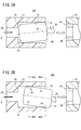
- FIG. 3A is a cross-sectional view taken along line IIIA-IIIA in FIG. 2B
- FIG. 3B is a cross-sectional view taken along line IIIB-IIIB in FIG. 2B.
- FIG. 6 is a partially omitted vertical sectional view showing a third state of the rotation driving device for explaining the principle of rotation of a rotating body.
- 5A is a cross-sectional view taken along line VA-VA in FIG. 4
- FIG. 5B is a cross-sectional view taken along line VB-VB in FIG. It is a cross-sectional explanatory drawing for demonstrating the state which the rotary body is rotating.
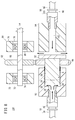
- FIG. 6 is a partially omitted longitudinal sectional view of a rotary drive device according to a second embodiment of the present invention. It is a partial omission longitudinal cross-sectional view of the rotational drive apparatus which concerns on 3rd Embodiment of this invention.
- FIG. 6 is a partially omitted vertical sectional view of a rotary drive device according to a fourth embodiment of the present invention.
- FIG. 10A is a partially omitted longitudinal sectional view of a rotary drive device according to a fifth embodiment of the present invention
- FIG. 10B is a partially omitted vertical sectional view showing a driving start state of the rotary drive device.
- It is a partially abbreviated longitudinal cross-sectional view of a rotary drive device according to a sixth embodiment of the present invention.
- FIG. 3 is a partially omitted longitudinal sectional view of the first experimental apparatus according to the first embodiment of the present invention. It is the graph which showed the experimental result obtained by the 1st experimental apparatus.
- FIG. 6 is a partially omitted longitudinal sectional view of a second experimental apparatus according to a second embodiment of the present invention. It is the graph which showed the experimental result obtained by the 2nd experimental apparatus.
- a rotary drive device 10A As shown in FIG. 1A, a rotary drive device 10A according to the present embodiment is arranged in a first housing 12, a second housing 14, and a first housing 12 that are configured in a cylindrical shape (cylindrical in the present embodiment).
- the fluid supply unit 18 for supplying a working fluid for applying fluid pressure to one end surface of the rotating body 16
- Power transmission part (power transmission means) 22 a movement restriction part (movement restriction means) 24 provided in the second housing 14 for restricting movement of the rotating body 16 to the other end side, and provided in the second housing 14.
- a bearing 26 that supports the output shaft 20.
- the first housing 12 is made of a nonmagnetic material, for example, a polymer material.
- a polymer material examples include polyurethane, polyacetal, MC nylon, PTFE (Teflon: registered trademark), and the like.
- the first housing 12 has a working channel 28 provided on one end side of the first housing 12, and a disposition hole 30 provided on the other end side of the first housing 12 and communicating with the working channel 28. Is formed.
- the working channel 28 is a channel through which a working fluid for applying fluid pressure to one end surface of the rotating body 16 flows.
- the rotating body 16 is arranged in the arrangement hole 30.
- the hole diameter of the arrangement hole 30 is slightly larger than the outer diameter of the rotating body 16.
- a predetermined gap (clearance) is provided between the wall surface (inner peripheral surface) 31 constituting the arrangement hole 30 and the outer peripheral surface of the rotary body 16 in a state where the rotary body 16 is arranged in the arrangement hole 30. S will be formed.
- the size of the gap S (the dimension obtained by subtracting the diameter of the rotating body 16 from the diameter of the arrangement hole 30) is preferably set in the range of several ⁇ m to several hundred ⁇ m. This is because when the gap S is set outside the above range, the rotating body 16 cannot be efficiently rotated.
- the hole diameter of the arrangement hole 30 is set larger than the flow path diameter of the working flow path 28. That is, a step is formed at the boundary between the working channel 28 and the arrangement hole 30.
- a stopper portion 32 that contacts one end surface of the rotating body 16 is formed on the wall surface of the step portion that faces the other end of the first housing 12.
- Rotating body 16 is composed of a neodymium magnet. However, you may comprise the rotary body 16 with various magnets (for example, a salium cobalt magnet etc.) other than a neodymium magnet. The total length of the rotating body 16 is set to be substantially the same as the depth dimension of the arrangement hole 30.
- the fluid supply unit 18 includes an introduction flow path 34 for guiding the working fluid from a fluid supply source (not shown), and a joint portion 36 that connects the introduction flow path 34 to the first housing 12.
- the joint portion 36 is screwed to the opening on one end side of the working channel 28. Thereby, the introduction flow path 34 and the working flow path 28 communicate with each other through the joint portion 36.
- the working fluid used in this embodiment for example, various fluids such as air, water, and oil are used.
- the working fluid may be a fluid (compressed fluid) compressed by a predetermined pump, a compressor, or the like, or may be a liquid that is freely dropped from vertically above the working channel 28. That is, the working fluid may be any fluid as long as a predetermined fluid pressure can be applied to one end surface of the rotating body 16.
- the rotating body 16 and the output shaft 20 are arranged coaxially.
- the power transmission unit 22 includes a spline hole 38 formed in the other end surface of the rotating body 16 and a spline unit 40 formed in one end portion of the output shaft 20 and fitted into the spline hole 38. Thereby, the rotational force of the rotating body 16 can be reliably transmitted to the output shaft 20.
- the second housing 14 can be made of any material, but is made of the same material as that of the first housing 12, for example.
- An inner hole 41 having a hole diameter substantially the same as the hole diameter of the arrangement hole 30 is formed in the second housing 14. Further, as can be seen from FIG. 1A, the second housing 14 is disposed such that the inner hole 41 faces the arrangement hole 30 of the first housing 12 with a predetermined distance therebetween.
- the movement restricting portion 24 has a fixed magnet 42 fixed to one end of the inner hole 41 of the second housing 14 by press fitting or the like so as to repel the rotating body 16.
- the fixed magnet 42 faces the rotating body 16.
- any magnet can be used as the fixed magnet 42, but a neodymium magnet is preferably used. This is because a relatively large repulsive force can be generated by using a neodymium magnet.
- An insertion hole 44 through which the output shaft 20 is inserted is formed in the fixed magnet 42. That is, the fixed magnet 42 is configured in an annular shape (in the present embodiment, an annular shape).
- the bearing 26 is fixed to the other end side of the inner hole 41 of the second housing 14 by press fitting or the like.
- a rolling bearing is illustrated as the bearing 26, but the bearing 26 may of course be a sliding bearing or the like.
- a working fluid is supplied to the introduction flow path 34 from a fluid supply source (not shown).
- the working fluid guided from the introduction channel 34 to the working channel 28 via the joint portion 36 flows along the axial direction of the rotating body 16 and hits one end surface of the rotating body 16. As a result, the fluid pressure of the working fluid acts on one end surface of the rotating body 16.
- the rotating body 16 moves to the other end side and is separated from the stopper portion 32 (see FIG. 1B).
- the rotating body 16 moved to the other end side stops moving in the axial direction at a position where the pressing force of the working fluid and the repulsive force of the fixed magnet 42 are balanced. That is, the rotating body 16 does not completely escape from the arrangement hole 30.
- the working fluid in the working channel 28 flows into a space formed on one end side of the rotating body 16, and the gap S between the outer peripheral surface of the rotating body 16 and the inner peripheral surface 31 constituting the arrangement hole 30. It flows out from the opening part of the other end side of the arrangement
- the output shaft 20 connected to the rotating body 16 also rotates together, so that the rotational force of the rotating body 16 is output to the outside via the output shaft 20.
- the output shaft 20 is pivotally supported by the bearing 26, it is possible to suitably suppress the rotational shake.
- FIG. 2A to 6 schematically show the configuration of the above-described embodiment in a partially exaggerated or omitted manner for convenience.
- the rotating body 16 moves away from the stopper portion 32 and moves to the other end side.
- the rotating body 16 does not rotate and hits the inner peripheral surface 31 constituting the arrangement hole 30 along the direction orthogonal to the axis Ax (while emitting vibration sound). Swing randomly.
- the rotating body 16 has its axis Ax inclined with respect to the center line O of the arrangement hole 30 and repeats the reversal of the inclination randomly.
- the second contact point P2 between the other end side and the inner peripheral surface 31 is 180 ° out of phase in the circumferential direction of the arrangement hole 30.
- a relatively large first gap S1 is formed at one end side of the rotating body 16 at a position that is 180 ° out of phase with the first contact point P1, and a second contact point is formed at the other end side of the rotating body 16.
- a relatively large second gap S2 is formed at a position that is 180 ° out of phase with respect to P2 (see FIG. 2B).
- the gap between the line segment L connecting the first contact point P1 and the second contact point P2a on the outer peripheral surface of the rotating body 16 and the inner peripheral surface 31 becomes relatively narrow.
- the pressure of the working fluid does not decrease much in the region on the one end face side of the rotating body 16 (first region).
- the pressure of the working fluid is moderately lower than that in the first region. .
- the working fluid circulates in the space (low pressure space) widened by the phase shift, not the space narrowed by the phase shift (high pressure space, space near the line segment L). To come. At this time, the flow rate of the working fluid increases as the pressure approaches the low outlet (the pressure of the working fluid decreases).
- the thrust along the direction of the arrow X acts on the rotating body 16 and the working fluid flowing from the first gap S1 toward the second gap S2 (in the widened space) and the outer peripheral surface of the rotating body 16
- the rotating body 16 rotates in a state where the phase difference between the first contact point P1 and the second contact point P2a is maintained.
- the rotating body 16 rotates clockwise along the inner peripheral surface 31 constituting the arrangement hole 30 while rotating counterclockwise when viewed from one end surface side of the rotating body 16. .
- the rotating body 16 rotates stably and continuously in a state where the phase difference between the first contact point P1 and the second contact point P2a is maintained.
- the rotating body 16 rotates clockwise as viewed from one end side thereof. It will rotate counterclockwise along the inner peripheral surface 31 which comprises the arrangement
- the rotational drive device 10 ⁇ / b> A As described above, according to the rotational drive device 10 ⁇ / b> A according to the present embodiment, the outer peripheral surface of the columnar rotating body 16 disposed in the disposition hole 30 and the inner peripheral surface 31 constituting the disposition hole 30. With a predetermined gap S formed between them, fluid pressure can be applied to one end surface of the rotating body 16 and the working fluid can be circulated through the gap S. Therefore, the rotating body 16 is rotated to rotate the rotating body 16. Force can be output from the output shaft 20. As a result, the apparatus itself can be configured simply and compactly, and the manufacturing cost can be reduced.
- the rotating body 16 when the rotating body 16 is composed of a neodymium magnet (magnet) and the first housing 12 is composed of polyacetal, the rotating body 16 can be reliably secured even with a relatively low working fluid pressure (working pressure). Can be rotated. This will also be described in the first and second embodiments described later.
- working pressure working fluid pressure
- the fixed magnet 42 is disposed opposite to the other end surface of the rotating body 16, the movement of the rotating body 16 to the other end side is restricted in a non-contact manner by the repulsive force of the fixed magnet 42. be able to. That is, since contact resistance (friction) or the like does not occur between the rotating body 16 and the fixed magnet 42, it is possible to suppress a decrease in rotational force due to movement limitation of the rotating body 16.
- the apparatus since the output shaft 20 is inserted through the insertion hole 44 of the fixed magnet 42 in a state where the rotating body 16 and the output shaft 20 are arranged coaxially, the apparatus itself can be suitably downsized.
- the position of the rotating body 16 with respect to the arrangement hole 30 in the stopped state can be made substantially constant. Therefore, it can suppress that the rotation characteristic of the rotary body 16 changes for every drive of 10 A of rotation drive devices.
- the rotating body 16 and the output shaft 20 are connected via the power transmission unit 22, the rotational force of the rotating body 16 can be reliably transmitted to the output shaft 20.
- This embodiment is not limited to the configuration described above.
- the rotating body 16 and the output shaft 20 may be integrally formed.
- the rotational force of the rotating body 16 can be directly used as the rotational force of the output shaft 20.
- a rotary drive device 10B according to a second embodiment of the present invention will be described with reference to FIG. Note that in the rotary drive device 10B according to the second embodiment, the same components as those of the rotary drive device 10A according to the first embodiment are denoted by the same reference numerals, and detailed description thereof is omitted. The same applies to a fourth embodiment and a fifth embodiment described later.
- the rotation driving device 10 ⁇ / b> B includes a rotating body 50 disposed in the arrangement hole 30 so as to protrude from the arrangement hole 30 of the first housing 12, and the other end portion of the rotation body 50.
- a power transmission unit (power transmission means) 52 provided on the output body 54, an output shaft 54 disposed parallel to the axis of the rotating body 50, and a support mechanism 56 that supports the output shaft 54.
- the disk-shaped fixed magnet 64 of the movement restricting portion 62 is fixed to the hole 60 of the second housing 58 having a substantially U-shaped cross section by press fitting or the like.
- the total length of the rotating body 50 is set larger than the depth of the arrangement hole 30. Therefore, the other end portion of the rotating body 50 protrudes from the arrangement hole 30 in a stopped state (a state where one end surface of the rotating body 50 is in contact with the stopper portion 32). Thereby, it is possible to prevent the power transmission unit 52 from hitting the first housing 12 in the stopped state.
- the power transmission unit 52 is configured as a gear mechanism, and a first gear 66 fixed to the other end of the rotating body 50 and a second gear meshed with the first gear 66 while being fixed to the output shaft 54. 68.
- the support mechanism 56 includes a first support portion 70 configured in a cylindrical shape, a first bearing 74 that pivotally supports one end portion of the output shaft 54 in a state of being disposed in the inner hole 72 of the first support portion 70, and It has the 2nd support part 76 comprised by the cylindrical shape, and the 2nd bearing 80 which pivotally supports the other end side of the output shaft 54 in the state arrange
- rolling bearings are illustrated as the first bearing 74 and the second bearing 80.
- the first bearing 74 and the second bearing 80 may of course be sliding bearings.
- the rotation drive device 10B according to the present embodiment can achieve the same effects as the rotation drive device 10A according to the first embodiment described above.
- the present embodiment is not limited to the configuration described above.
- the power transmission unit 52 is not limited to a gear mechanism, and may be a structure using a V belt, a chain, or the like.
- a rotary drive device 10C according to a third embodiment of the present invention will be described with reference to FIG. Note that in the rotary drive device 10C according to the third embodiment, the same components as those of the rotary drive device 10B according to the second embodiment are denoted by the same reference numerals, and detailed description thereof is omitted.
- the rotational drive device 10C is different in the configuration of the movement limiting unit 90 from the configuration of the movement limiting unit 62 of the rotary driving device 10B described above.
- the movement restricting portion 90 of the rotation driving device 10 ⁇ / b> C includes a pressure receiving portion (pressure receiving plate) 92 fixed to the other end surface of the rotating body 50 and a second housing 94 that presses the pressure receiving portion 92 toward one end side of the rotating body 50.
- a fluid supply unit 96 for supplying a fluid for the purpose.
- the pressure receiving portion 92 is formed in a disc shape, and has an outer diameter larger than the outer diameter of the rotating body 50. That is, the pressure receiving portion 92 is located on the radially outer side of the rotating body 50.
- the second housing 94 configured in a cylindrical shape is spaced from the pressure receiving portion 92.
- the fluid supply unit 96 includes an introduction channel 98 for guiding fluid from a supply source (not shown), and a joint unit 100 that couples the introduction channel 98 to the second housing 94.
- the joint 100 is screwed to the opening on the other end side of the inner hole (fluid channel) 102 of the second housing 94. Thereby, the introduction flow path 98 communicates with the inner hole 102 of the second housing 94 via the joint portion 100.
- the fluid guided to the inner hole 102 of the second housing 94 for example, various fluids such as air, water, and oil are used. Further, the fluid may be the same fluid as the driving fluid or may be a fluid different from the driving fluid. When the fluid is the same fluid as the driving fluid, the fluid supply source can be shared, so that the configuration of the rotation driving device 10C can be simplified.
- the rotating body 50 can be made of a material other than a magnet (for example, a metal material, a polymer material, etc.), and the first housing 12 can be made of a material other than a nonmagnetic material (for example, Metal material etc.).
- the fluid guided to the introduction flow path 98 from a fluid supply source passes through the inner hole 102 of the second housing 94 via the joint portion 100 and hits the other end face of the pressure receiving portion 92, and the pressure receiving portion 92 and It flows out from the gap between the second housing 94.
- the pressure receiving part 92 is pushed by the one end side of the rotary body 50, the movement of the other end side of the rotary body 50 will be restrict
- the rotary drive device 10C according to the present embodiment can achieve the same effects as the rotary drive device 10B according to the second embodiment described above.
- the pressure receiving portion 92 provided at the other end of the rotating body 50 can be pressed against the one end side of the rotating body 50 by the fluid guided from the introduction flow path 98. The movement to the other end side can be surely limited. Further, since the pressure receiving portion 92 is located on the outer side in the radial direction of the rotating body 50, the fluid guided from the inner hole 102 of the second housing 94 is prevented from flowing into the arrangement hole 30 of the first housing 12. In addition, the pressure receiving area with which the fluid of the pressure receiving portion 92 contacts can be made relatively large.
- the pressure receiving portion 92 may be fixed to the other end portion of the outer peripheral surface of the rotating body 50. That is, the pressure receiving portion 92 may be configured in an annular shape. Even in this case, the same effect as the above-described configuration is obtained.
- a rotary drive device 10D according to a fourth embodiment of the present invention will be described with reference to FIG.
- the power transmission unit (power transmission means) 110 and the movement restriction unit 112 are configured with the power transmission unit 22 and the movement restriction unit 24 of the rotational drive device 10A according to the first embodiment.
- the configuration is different.
- the power transmission unit 110 of the rotational drive device 10D has a clutch unit 118 provided in a diameter-expanded part 116 formed at one end of the output shaft 114.
- the clutch portion 118 is configured to generate an appropriate friction while being in contact with the other end surface of the rotating body 16 and to be elastically deformable.
- the clutch part 118 can be comprised with resin materials, such as rubber
- the movement restricting portion 112 has a thrust bearing 124 fixed to one end side of the inner hole 122 of the second housing 120 by press fitting or the like.
- the thrust bearing 124 can receive a force in a direction toward the other end side of the output shaft 114.
- the rotating body 16 can be made of a material other than a magnet (for example, a metal material or a polymer material), and the first housing 12 can be made of a material other than a nonmagnetic material (for example, Metal material etc.).
- the rotational drive device 10D according to the present embodiment can achieve the same effects as the rotational drive device 10A according to the first embodiment described above.
- a rotary drive device 10E according to a fifth embodiment of the present invention will be described with reference to FIGS. 10A and 10B.
- the rotational drive device 10E differs in the structure of the power transmission part (power transmission means) 130 from the structure of the power transmission part 22 of 10 A of rotational drive apparatuses which concern on 1st Embodiment.
- the power transmission unit 130 of the rotational drive device 10E includes a hole 132 formed on the other end surface of the rotating body 16, a pin 134 press-fitted into the hole 132, and a reduced diameter portion formed on the other end of the pin 134. 136 and a connecting tube 142 that connects the reduced diameter portion 140 formed on one end side of the output shaft 138.
- the connecting tube 142 is configured to be elastically deformable, and the reduced diameter portion 136 of the pin 134 is firmly fitted to one end side thereof, and the reduced diameter portion 140 of the output shaft 138 is firmly fitted to the other end side thereof. .
- the connecting tube 142 is inserted through the insertion hole 44 of the fixed magnet 42.
- the connection tube 142 can be formed of a flexible member, and can be formed of, for example, silicon rubber.
- the rotary drive device 10E according to the present embodiment can achieve the same effects as the rotary drive device 10A according to the first embodiment described above. Further, as shown in FIG. 10B, even when the rotating body 16 is inclined or decentered at the start of driving of the rotation driving device 10E, the connecting tube 142 is elastically deformed in accordance with the movement of the rotating body 16 (rotating body). 16 can be flexibly absorbed), and the output shaft 138 can be prevented from being inclined or eccentric together with the rotating body 16.
- the rotary drive device 10 ⁇ / b> F includes a first housing 150 configured in a cylindrical shape, and an output shaft 138 disposed on one end side of the rotary body 16 provided in the first housing 150.
- a bearing 26 that supports the shaft 138.
- the first housing 150 includes a bearing mounting hole 156 that is provided on one end side of the first housing 150 and into which the bearing 26 is press-fitted, a working channel 28 that communicates with the bearing mounting hole 156, and the other end of the first housing 150.
- a disposition hole 30 provided on the side and communicating with the working channel 28 is formed.
- a connection tube 142 that constitutes the power transmission unit 130 is disposed in the working flow path 28.
- the first housing 150 is formed with a pair of supply ports 158 and 160 that open to the wall surface constituting the working flow path 28 and guide the working fluid to the working flow path 28.
- a fluid supply unit 162 is connected to the supply port 158, and a fluid supply unit 164 is connected to the supply port 160.
- Each fluid supply part 162,164 has the introduction flow path 34 and the joint part 36, and has the same structure as the fluid supply part 18 of 1st Embodiment.
- the movement restricting portion 154 has a fixed magnet 168 fixed to a hole 166 having a substantially U-shaped cross section formed in the second housing 152 by press-fitting or the like.
- the fixed magnet 168 is formed in a disk shape, for example, and applies a repulsive force to the rotating body 16.
- the rotary drive device 10F can achieve the same effects as those of the fifth embodiment described above. Further, an output shaft 138 is provided on the side opposite to the side where the fixed magnet 168 is located with respect to the rotating body 16, and the power transmission unit 130 (the connecting tube 142 is provided in the working channel 28 for guiding the working fluid to the rotating body 16. Therefore, it is not necessary to form a hole through which the connecting tube 142 and the like are inserted into the fixed magnet 168. That is, in this embodiment, since the solid fixed magnet 168 can be used, the repulsion acting on the rotating body 16 is compared with the case where a hollow fixed magnet having the same outer diameter as the fixed magnet 168 is used. It is possible to strengthen the power. Thereby, the rotary body 16 can be rotated more stably.
- the first experimental device 170 includes a rotation drive device 10E according to the fifth embodiment described above, a detection magnet 172 fixed to the other end of the output shaft 138 constituting the rotation drive device 10E, A coil 174 disposed in the vicinity of the detection magnet 172 and a measuring device (oscilloscope) 176 for measuring an induced current (voltage) generated in the coil 174 are provided.
- the rotating body 16 and the fixed magnet 42 are composed of neodymium magnets.
- the detection magnet 172 is fixed to the output shaft 138 so that the N pole and the S pole are positioned in a direction orthogonal to the axis of the output shaft 138.
- the relative position between the N pole (S pole) of the detection magnet 172 and the coil 174 changes at a predetermined cycle.
- an induction current is generated in the coil 174 by electromagnetic induction.
- first housings 12 made of polyacetal, polyurethane, and aluminum are used, and the pressure of the working fluid (working pressure) that acts on the rotating body 16 is changed stepwise.
- working pressure working pressure
- a voltage waveform based on the induced current flowing in the coil 174 under the above experimental conditions was acquired, and the rotation speed of the output shaft 138 was calculated from this waveform.
- FIG. 13 shows the experimental results according to the first example.
- FIG. 13 is a graph showing the number of rotations with respect to the operating pressure in the various first housings 12.
- the experimental results using the first housing 12 made of polyacetal are shown by solid lines
- the experimental results using the first housing 12 made of polyurethane are shown by broken lines
- the first housing made of aluminum is shown with the dashed-dotted line.
- the output shaft 138 rotates even in the low pressure region (0.05 MPa) of the working fluid that did not rotate in the first housing 12 made of polyurethane or aluminum. Was observed.
- the second experimental device 180 includes the rotation drive device 10 ⁇ / b> C according to the third embodiment described above, and the same detection magnet 172, coil 174, and measuring device 176 as the first experimental device 170. . That is, in the second experimental device 180, the detection magnet 172 is fixed to the other end of the output shaft 54 constituting the rotary drive device 10C.
- the rotating body 50 is composed of a neodymium magnet.
- FIG. 15 is a graph similar to FIG. 13, in which the experimental results using the first housing 12 made of polyacetal are shown by solid lines, and the experimental results using the first housing 12 made of polyurethane are shown by broken lines. Experimental results using the first housing 12 made of aluminum are indicated by a one-dot chain line.
- the output shaft 54 rotates even in the low pressure region (0.10 MPa) of the working fluid that did not rotate in the first housing 12 made of polyurethane or aluminum. Was observed. Furthermore, when the first housing 12 made of polyacetal is used, the rotational speed of the output shaft becomes higher over the entire operating pressure range in which the experiment was performed than when the other two types of first housings 12 were used. Was observed.
- the rotary drive devices 10A to 10F can be used for various purposes. For example, if a generator is connected to the output shafts 20, 54, 114, and 138 of the rotary drive devices 10A to 10F, the power generator can be used. Further, if a fan or the like is connected to the output shafts 20, 54, 114, 138, it can be used as a blower.
- the present invention is not limited to the above-described embodiment, and it is naturally possible to adopt various configurations without departing from the gist of the present invention.
Abstract
Description
図1Aに示すように、本実施形態に係る回転駆動装置10Aは、筒状(本実施形態では、円筒状)に構成された第1ハウジング12と第2ハウジング14と、第1ハウジング12に配設された円柱状の回転体16と、回転体16の一端面に流体圧力を作用させるための作動流体を供給する流体供給部18と、回転体16の回転力を出力軸20に伝達するための動力伝達部(動力伝達手段)22と、第2ハウジング14に設けられて回転体16の他端側への移動を制限する移動制限部(移動制限手段)24と、第2ハウジング14に設けられて出力軸20を軸支する軸受26とを備えている。 (First embodiment)
As shown in FIG. 1A, a
次に、本発明の第2実施形態に係る回転駆動装置10Bについて図7を参照しながら説明する。なお、第2実施形態に係る回転駆動装置10Bにおいて、第1実施形態に係る回転駆動装置10Aと同一の構成要素には同一の参照符号を付し、詳細な説明を省略する。後述する第4実施形態及び第5実施形態についても同様である。 (Second Embodiment)
Next, a
次に、本発明の第3実施形態に係る回転駆動装置10Cについて図8を参照しながら説明する。なお、第3実施形態に係る回転駆動装置10Cにおいて、第2実施形態に係る回転駆動装置10Bと同一の構成要素には同一の参照符号を付し、詳細な説明を省略する。 (Third embodiment)
Next, a
次に、本発明の第4実施形態に係る回転駆動装置10Dについて図9を参照しながら説明する。図9に示すように、回転駆動装置10Dは、動力伝達部(動力伝達手段)110と移動制限部112の構成が第1実施形態に係る回転駆動装置10Aの動力伝達部22と移動制限部24の構成と異なる。 (Fourth embodiment)
Next, a
次に、本発明の第5実施形態に係る回転駆動装置10Eについて図10A及び図10Bを参照しながら説明する。図10Aに示すように、回転駆動装置10Eは、動力伝達部(動力伝達手段)130の構成が第1実施形態に係る回転駆動装置10Aの動力伝達部22の構成と異なる。 (Fifth embodiment)
Next, a
次に、本発明の第6実施形態に係る回転駆動装置10Fについて図11を参照しながら説明する。図11に示すように、回転駆動装置10Fにおいて、第5実施形態に係る回転駆動装置10Eと同一の構成要素には同一の参照符号を付し、詳細な説明を省略する。 (Sixth embodiment)
Next, a
先ず、第1実施例に係る実験装置(第1実験装置)170について説明する。図12に示すように、第1実験装置170は、上述した第5実施形態に係る回転駆動装置10Eと、回転駆動装置10Eを構成する出力軸138の他端に固着された検出磁石172と、検出磁石172の近傍に配置したコイル174と、コイル174に発生した誘導電流(電圧)を測定する測定装置(オシロスコープ)176とを備えている。なお、回転体16及び固定磁石42はネオジム磁石で構成されている。 (First embodiment)
First, an experimental apparatus (first experimental apparatus) 170 according to the first embodiment will be described. As shown in FIG. 12, the first
次に、第2実施例に係る実験装置(第2実験装置)180について説明する。図14に示すように、第2実験装置180は、上述した第3実施形態に係る回転駆動装置10Cと、第1実験装置170と同様の検出磁石172、コイル174及び測定装置176を備えている。すなわち、第2実験装置180では、回転駆動装置10Cを構成する出力軸54の他端に検出磁石172を固着している。なお、回転体50は、ネオジム磁石で構成されている。 (Second embodiment)
Next, an experimental apparatus (second experimental apparatus) 180 according to the second embodiment will be described. As shown in FIG. 14, the second
Claims (8)
- 円柱状の回転体(16、50)と、
前記回転体(16、50)を配設する配設孔(30)が形成されたハウジング(12、150)と、
前記回転体(16、50)の一端面に流体圧力を作用させるための作動流体が流通する作動流路(28)と、
前記回転体(16、50)の他端側への移動を制限する移動制限手段(24、62、90、112、154)と、
前記回転体(16、50)の回転力を外部に出力するための出力軸(20、54、114、138)と、
を備え、
前記回転体(16、50)の外周面と前記配設孔(30)を構成する壁面(31)との間には前記作動流体が流通する所定の隙間(S)が形成されている、
ことを特徴とする回転駆動装置(10A~10F)。 A cylindrical rotating body (16, 50);
A housing (12, 150) in which an arrangement hole (30) for arranging the rotating body (16, 50) is formed;
A working flow path (28) through which a working fluid for applying fluid pressure to one end surface of the rotating body (16, 50) flows;
Movement restriction means (24, 62, 90, 112, 154) for restricting movement of the rotating body (16, 50) to the other end side;
An output shaft (20, 54, 114, 138) for outputting the rotational force of the rotating body (16, 50) to the outside;
With
A predetermined gap (S) through which the working fluid flows is formed between the outer peripheral surface of the rotating body (16, 50) and the wall surface (31) constituting the arrangement hole (30).
A rotary drive device (10A to 10F) characterized by that. - 請求項1記載の回転駆動装置(10A~10F)において、
前記回転体(16、50)は、磁石で構成され、
前記ハウジング(12、150)は、非磁性材料で構成される、
ことを特徴とする回転駆動装置(10A~10F)。 The rotary drive device (10A to 10F) according to claim 1,
The rotating body (16, 50) is composed of a magnet,
The housing (12, 150) is made of a non-magnetic material,
A rotary drive device (10A to 10F) characterized by that. - 請求項2記載の回転駆動装置(10A~10F)において、
前記回転体(16、50)は、ネオジム磁石で構成され、
前記ハウジング(12、150)は、ポリアセタールで構成される、
ことを特徴とする回転駆動装置(10A~10F)。 The rotary drive device (10A to 10F) according to claim 2,
The rotating body (16, 50) is composed of a neodymium magnet,
The housing (12, 150) is composed of polyacetal,
A rotary drive device (10A to 10F) characterized by that. - 請求項2又は3に記載の回転駆動装置(10A、10B、10E、10F)において、
前記移動制限手段(24、62、154)は、前記回転体(16、50)の他端面に対向して配設された状態で当該回転体(16、50)と反発する固定磁石(42、64、168)を有する、
ことを特徴とする回転駆動装置(10A、10B、10E、10F)。 In the rotation drive device (10A, 10B, 10E, 10F) according to claim 2 or 3,
The movement restricting means (24, 62, 154) is disposed opposite to the other end surface of the rotating body (16, 50), and the stationary magnet (42, 42) repels the rotating body (16, 50). 64, 168),
A rotary drive device (10A, 10B, 10E, 10F) characterized by the above. - 請求項4記載の回転駆動装置(10A、10E)において、
前記固定磁石(42)は、環状に構成されている、
ことを特徴とする回転駆動装置(10A、10E)。 The rotary drive device (10A, 10E) according to claim 4,
The fixed magnet (42) is configured in an annular shape,
Rotation drive device (10A, 10E) characterized by this. - 請求項1~3のいずれか1項に記載の回転駆動装置(10C)において、
前記回転体(50)は、当該回転体(50)の他端部が前記配設孔(30)から突出するようにして当該配設孔(30)に配設されており、
前記移動制限手段(90)は、前記回転体(50)の他端部に対して当該回転体(50)の径方向外側に位置するように設けられた受圧部(92)と、
前記受圧部(92)を前記回転体(50)の一端側に押圧するための流体が流通する流体流路(102)と、を有する、
ことを特徴とする回転駆動装置(10C)。 The rotary drive device (10C) according to any one of claims 1 to 3,
The rotating body (50) is arranged in the arrangement hole (30) such that the other end of the rotating body (50) protrudes from the arrangement hole (30).
The movement restricting means (90) includes a pressure receiving portion (92) provided so as to be positioned on the radially outer side of the rotating body (50) with respect to the other end of the rotating body (50).
A fluid flow path (102) through which a fluid for pressing the pressure receiving portion (92) against one end of the rotating body (50) flows.
A rotary drive device (10C) characterized by the above. - 請求項4~6のいずれか1項に記載の回転駆動装置(10A~10F)において、
前記回転体(16、50)の一端側の移動を制限するストッパ部(32)をさらに備える、
ことを特徴とする回転駆動装置(10A~10F)。 The rotary drive device (10A to 10F) according to any one of claims 4 to 6,
A stopper portion (32) for restricting movement of one end of the rotating body (16, 50);
A rotary drive device (10A to 10F) characterized by that. - 請求項1~7のいずれか1項に記載の回転駆動装置(10A~10F)において、
前記回転体(16、50)の回転力を前記出力軸(20、54、114、138)に伝達するための動力伝達手段(22、52、110、130)をさらに備える、
ことを特徴とする回転駆動装置(10A~10F)。 The rotary drive device (10A to 10F) according to any one of claims 1 to 7,
Power transmission means (22, 52, 110, 130) for transmitting the rotational force of the rotating body (16, 50) to the output shaft (20, 54, 114, 138) is further provided.
A rotary drive device (10A to 10F) characterized by that.
Priority Applications (6)
| Application Number | Priority Date | Filing Date | Title |
|---|---|---|---|
| JP2014534842A JP5671754B1 (en) | 2013-03-05 | 2013-03-05 | Rotation drive |
| EP13869852.7A EP2966295B1 (en) | 2013-03-05 | 2013-03-05 | Rotary drive device |
| KR1020157003493A KR101643109B1 (en) | 2013-03-05 | 2013-03-05 | Rotary drive device |
| US14/368,222 US10267285B2 (en) | 2013-03-05 | 2013-03-05 | Rotation drive apparatus |
| PCT/JP2013/055921 WO2014136198A1 (en) | 2013-03-05 | 2013-03-05 | Rotary drive device |
| CN201380042091.9A CN105121839B (en) | 2013-03-05 | 2013-03-05 | Rotational driving device |
Applications Claiming Priority (1)
| Application Number | Priority Date | Filing Date | Title |
|---|---|---|---|
| PCT/JP2013/055921 WO2014136198A1 (en) | 2013-03-05 | 2013-03-05 | Rotary drive device |
Publications (1)
| Publication Number | Publication Date |
|---|---|
| WO2014136198A1 true WO2014136198A1 (en) | 2014-09-12 |
Family
ID=51490764
Family Applications (1)
| Application Number | Title | Priority Date | Filing Date |
|---|---|---|---|
| PCT/JP2013/055921 WO2014136198A1 (en) | 2013-03-05 | 2013-03-05 | Rotary drive device |
Country Status (6)
| Country | Link |
|---|---|
| US (1) | US10267285B2 (en) |
| EP (1) | EP2966295B1 (en) |
| JP (1) | JP5671754B1 (en) |
| KR (1) | KR101643109B1 (en) |
| CN (1) | CN105121839B (en) |
| WO (1) | WO2014136198A1 (en) |
Cited By (2)
| Publication number | Priority date | Publication date | Assignee | Title |
|---|---|---|---|---|
| WO2016135914A1 (en) * | 2015-02-26 | 2016-09-01 | 有限会社中▲野▼製作所 | Rotational drive device |
| JP2021146316A (en) * | 2020-03-23 | 2021-09-27 | 栗田工業株式会社 | Water treatment system |
Citations (7)
| Publication number | Priority date | Publication date | Assignee | Title |
|---|---|---|---|---|
| JPS60204978A (en) | 1984-03-28 | 1985-10-16 | Hitachi Constr Mach Co Ltd | Radial-piston type hydraulic rotary machine |
| JPH09303273A (en) | 1996-05-16 | 1997-11-25 | Mitsubishi Heavy Ind Ltd | Vane type fluid rotary machine |
| US6702038B1 (en) * | 1998-05-22 | 2004-03-09 | Miroslav Sedlacek | Hydraulic motor |
| WO2005071256A1 (en) * | 2004-01-23 | 2005-08-04 | Miroslav Simera | Rolling fluid machine especially with a liquid spraying at the output |
| WO2005106205A1 (en) * | 2004-04-28 | 2005-11-10 | Miroslav Sterba | Bladeless fluid machine |
| JP4124274B2 (en) * | 1996-10-17 | 2008-07-23 | シメラ ミロスラフ | Fluid machine |
| JP2010265797A (en) | 2009-05-14 | 2010-11-25 | Shimadzu Corp | Gear pump or motor |
Family Cites Families (30)
| Publication number | Priority date | Publication date | Assignee | Title |
|---|---|---|---|---|
| US2436246A (en) * | 1944-10-21 | 1948-02-17 | Earl W Braga | Air-cooled explosion turbine |
| US3198191A (en) * | 1962-04-02 | 1965-08-03 | Kinetic Heating Corp | Heat generator |
| FR1509938A (en) * | 1966-06-27 | 1968-01-19 | Rateau Soc | Improvement in axial stops of rotating machines and hydromagnetic stop |
| GB1373955A (en) * | 1971-04-03 | 1974-11-13 | Bullough W A | Combined viscosity pump and electric motor |
| NL7111948A (en) * | 1971-08-31 | 1973-03-02 | ||
| US3801214A (en) * | 1972-04-03 | 1974-04-02 | N Jonsson | Fluid pressure creating rotary device |
| US3861831A (en) * | 1973-12-03 | 1975-01-21 | Rule Industries | Vertical shaft impeller pump apparatus |
| US4008774A (en) * | 1974-10-22 | 1977-02-22 | Milano Martin B | Hydraulically powered drill press |
| US4378195A (en) * | 1976-12-10 | 1983-03-29 | Joseph Gamell Industries, Inc. | Pressure fluid motor |
| JPS6028502B2 (en) * | 1977-01-25 | 1985-07-05 | 株式会社モリタ製作所 | Bearing mechanism of dental air bearing handpiece |
| US4332428A (en) * | 1979-01-16 | 1982-06-01 | Matsushita Electric Industrial Co., Ltd. | Rotary mechanism with axial bearings |
| US4320927A (en) * | 1980-03-21 | 1982-03-23 | Sertich Anthony T | Dental drill with magnetic air turbine having magnetic bearings |
| EP0102713B1 (en) * | 1982-08-25 | 1987-09-02 | Imperial Chemical Industries Plc | Electrostatic entrainment pump for a spraying system |
| JPH0646036B2 (en) * | 1982-11-19 | 1994-06-15 | セイコー電子工業株式会社 | Axial flow molecular pump |
| GB8314522D0 (en) * | 1983-05-25 | 1983-06-29 | Mohsin M E | Fluid-powered rotary motor |
| US4483277A (en) * | 1983-06-02 | 1984-11-20 | Perkins Eugene W | Superheated liquid heating system |
| US4836758A (en) * | 1987-11-20 | 1989-06-06 | Copeland Corporation | Scroll compressor with canted drive busing surface |
| US5135374A (en) * | 1990-06-30 | 1992-08-04 | Kabushiki Kaisha Kobe Seiko Sho | Oil flooded screw compressor with thrust compensation control |
| US5188090A (en) * | 1991-04-08 | 1993-02-23 | Hydro Dynamics, Inc. | Apparatus for heating fluids |
| JPH08140993A (en) * | 1994-11-25 | 1996-06-04 | Koyo Seiko Co Ltd | Hand piece for dentistry |
| CZ7606U1 (en) | 1998-05-22 | 1998-07-10 | Miroslav Ing. Csc. Sedláček | Hydraulic motor |
| CZ9904624A3 (en) * | 1999-12-17 | 2001-12-12 | Miroslav Ing. Csc. Sedláček | Speed multiplier |
| US6896718B2 (en) * | 2000-09-12 | 2005-05-24 | Clearwater International Llc | Gas dehydration with cavitation regeneration of potassium formate dehydrating solution |
| US6595759B2 (en) * | 2001-07-30 | 2003-07-22 | Stella Maris Crosta | Centrifugal device for heating and pumping fluids |
| JP2004084897A (en) * | 2002-08-29 | 2004-03-18 | Seiko Instruments Inc | Dynamic pressure bearing, rotary body device and motor |
| ATE549516T1 (en) * | 2003-09-11 | 2012-03-15 | Bosch Gmbh Robert | ROTARY PISTON MACHINE |
| US7736061B2 (en) | 2004-06-11 | 2010-06-15 | Seiko Instruments Inc. | Fluid dynamic bearing motor, and recording-medium driving apparatus |
| JP4849507B2 (en) * | 2005-05-26 | 2012-01-11 | 日立アプライアンス株式会社 | Self-starting synchronous motor |
| CN1904351B (en) * | 2006-08-14 | 2010-05-12 | 王悦 | Pressure water cushion type biscrew hydraulic turbine |
| US8087907B2 (en) * | 2008-03-26 | 2012-01-03 | Ebara Corporation | Turbo vacuum pump |
-
2013
- 2013-03-05 KR KR1020157003493A patent/KR101643109B1/en active IP Right Grant
- 2013-03-05 US US14/368,222 patent/US10267285B2/en active Active
- 2013-03-05 JP JP2014534842A patent/JP5671754B1/en active Active
- 2013-03-05 WO PCT/JP2013/055921 patent/WO2014136198A1/en active Application Filing
- 2013-03-05 CN CN201380042091.9A patent/CN105121839B/en active Active
- 2013-03-05 EP EP13869852.7A patent/EP2966295B1/en active Active
Patent Citations (7)
| Publication number | Priority date | Publication date | Assignee | Title |
|---|---|---|---|---|
| JPS60204978A (en) | 1984-03-28 | 1985-10-16 | Hitachi Constr Mach Co Ltd | Radial-piston type hydraulic rotary machine |
| JPH09303273A (en) | 1996-05-16 | 1997-11-25 | Mitsubishi Heavy Ind Ltd | Vane type fluid rotary machine |
| JP4124274B2 (en) * | 1996-10-17 | 2008-07-23 | シメラ ミロスラフ | Fluid machine |
| US6702038B1 (en) * | 1998-05-22 | 2004-03-09 | Miroslav Sedlacek | Hydraulic motor |
| WO2005071256A1 (en) * | 2004-01-23 | 2005-08-04 | Miroslav Simera | Rolling fluid machine especially with a liquid spraying at the output |
| WO2005106205A1 (en) * | 2004-04-28 | 2005-11-10 | Miroslav Sterba | Bladeless fluid machine |
| JP2010265797A (en) | 2009-05-14 | 2010-11-25 | Shimadzu Corp | Gear pump or motor |
Cited By (2)
| Publication number | Priority date | Publication date | Assignee | Title |
|---|---|---|---|---|
| WO2016135914A1 (en) * | 2015-02-26 | 2016-09-01 | 有限会社中▲野▼製作所 | Rotational drive device |
| JP2021146316A (en) * | 2020-03-23 | 2021-09-27 | 栗田工業株式会社 | Water treatment system |
Also Published As
| Publication number | Publication date |
|---|---|
| EP2966295B1 (en) | 2020-04-22 |
| KR101643109B1 (en) | 2016-07-26 |
| KR20150036501A (en) | 2015-04-07 |
| CN105121839B (en) | 2017-10-03 |
| JPWO2014136198A1 (en) | 2017-02-09 |
| EP2966295A1 (en) | 2016-01-13 |
| US10267285B2 (en) | 2019-04-23 |
| US20150292468A1 (en) | 2015-10-15 |
| JP5671754B1 (en) | 2015-02-18 |
| CN105121839A (en) | 2015-12-02 |
| EP2966295A4 (en) | 2016-07-20 |
Similar Documents
| Publication | Publication Date | Title |
|---|---|---|
| RU2006102133A (en) | DEVICE FOR TRANSMISSION OF ROTARY MOTION TO A SLAVE SHAFT, IN PARTICULAR, FOR RECIRCULATION PUMPS FOR A FLUID | |
| JP5671754B1 (en) | Rotation drive | |
| JP2012062888A (en) | Pump unit | |
| JP6946552B2 (en) | Equipment with bearings inside the bearing | |
| EP1653061A1 (en) | Device for transmitting the rotating movement to a driven shaft, in particular for fluid recirculating pumps | |
| JP2013525710A (en) | Eccentric bearing | |
| MX2016011273A (en) | Fluid driving device, motor assembly and centrifugal friction clutch. | |
| KR102444631B1 (en) | Structure for motor | |
| TWI542787B (en) | Rotation drive apparatus | |
| US20090104057A1 (en) | Pump having magnetic coupling mechanism | |
| JP2010074975A5 (en) | ||
| US11499594B2 (en) | Magnetorheological fluid clutch apparatus with low permeability drums | |
| JP2006009898A (en) | Power transmission device | |
| JP5555372B2 (en) | Eccentric bearing | |
| JP2014001714A (en) | Uniaxial eccentric screw pump | |
| JP6995678B2 (en) | Rotational resistance generator | |
| JP2011152037A (en) | Stator, and device with rotor fitted thereon | |
| WO2016135914A1 (en) | Rotational drive device | |
| US11248683B2 (en) | Transmission and compressor system | |
| RU2683587C1 (en) | Built into electric motor magnetic gearbox | |
| JP5028602B2 (en) | Uniaxial eccentric screw pump | |
| JP6635694B2 (en) | Pump body, pump device, flow meter and generator | |
| JP2013234699A (en) | Magnetic coupling device | |
| CN109391118B (en) | Axial rotation linear motor | |
| JP2011158005A (en) | Wet clutch |
Legal Events
| Date | Code | Title | Description |
|---|---|---|---|
| WWE | Wipo information: entry into national phase |
Ref document number: 14368222 Country of ref document: US |
|
| WWE | Wipo information: entry into national phase |
Ref document number: 2013869852 Country of ref document: EP |
|
| ENP | Entry into the national phase |
Ref document number: 2014534842 Country of ref document: JP Kind code of ref document: A |
|
| 121 | Ep: the epo has been informed by wipo that ep was designated in this application |
Ref document number: 13869852 Country of ref document: EP Kind code of ref document: A1 |
|
| ENP | Entry into the national phase |
Ref document number: 20157003493 Country of ref document: KR Kind code of ref document: A |
|
| NENP | Non-entry into the national phase |
Ref country code: DE |