WO2014133057A1 - Multi-core fiber - Google Patents
Multi-core fiber Download PDFInfo
- Publication number
- WO2014133057A1 WO2014133057A1 PCT/JP2014/054806 JP2014054806W WO2014133057A1 WO 2014133057 A1 WO2014133057 A1 WO 2014133057A1 JP 2014054806 W JP2014054806 W JP 2014054806W WO 2014133057 A1 WO2014133057 A1 WO 2014133057A1
- Authority
- WO
- WIPO (PCT)
- Prior art keywords
- core
- cores
- refractive index
- center
- clad
- Prior art date
Links
Images


Classifications
-
- G—PHYSICS
- G02—OPTICS
- G02B—OPTICAL ELEMENTS, SYSTEMS OR APPARATUS
- G02B6/00—Light guides; Structural details of arrangements comprising light guides and other optical elements, e.g. couplings
- G02B6/02—Optical fibres with cladding with or without a coating
- G02B6/02042—Multicore optical fibres
-
- G—PHYSICS
- G02—OPTICS
- G02B—OPTICAL ELEMENTS, SYSTEMS OR APPARATUS
- G02B6/00—Light guides; Structural details of arrangements comprising light guides and other optical elements, e.g. couplings
- G02B6/02—Optical fibres with cladding with or without a coating
- G02B6/036—Optical fibres with cladding with or without a coating core or cladding comprising multiple layers
- G02B6/03605—Highest refractive index not on central axis
Definitions
- the present invention relates to a multi-core fiber that can suppress crosstalk.
- An optical fiber used in a currently popular optical fiber communication system has a structure in which the outer periphery of one core is surrounded by a clad, and information is transmitted by propagation of an optical signal in the core. Is done. In recent years, with the spread of optical fiber communication systems, the amount of information transmitted has increased dramatically.
- a plurality of signals are transmitted by light propagating through each core using a multi-core fiber in which the outer circumferences of the plurality of cores are surrounded by one clad. It has been known.
- Non-Patent Document 1 describes an example of a multi-core fiber.
- one core is arranged at the center of the clad, and six cores are arranged at equal intervals so as to surround the one core. That is, the core has a 1-6 arrangement.
- a multi-core fiber in which the core is 1-6-12 see Non-Patent Document 2 below.
- the cores are arranged on each lattice point of the triangular lattice so that the cores are arranged in a close-packed manner.
- a trench type multi-core fiber in which each core is surrounded by a low refractive index portion called a trench portion and includes the core and the low refractive index portion as a core element.
- a trench type multi-core fiber light propagating through the core is strongly confined by the core. Accordingly, light propagating through each core is suppressed from leaking out of each core element, and crosstalk between the cores can be reduced.
- K. Imamura et. Al. “19-core multi core fiber to realize high density space division multiplexing transmission,” in Proc. IEEE Photon. Soc. Summer Topical Meeting 2012, TuC4.3 (2012).
- K. Takenaga et al. “Reduction of crosstalk by stretch-assisted multi-core fiber,” OFC2011, OWJ4 (2011).
- the cores are arranged as in Patent Documents 1 to 3, the core arranged at the center is surrounded by a plurality of cores on the outer peripheral side, so that crosstalk is likely to occur between the cores on the outer peripheral side.
- the cutoff wavelength tends to become longer due to the effect of high-order mode confinement by a plurality of surrounding core elements.
- the communication quality of the specific core is likely to deteriorate. For example, if the core elements are arranged 1-6, the cutoff wavelength of the central core tends to be long.
- an object of the present invention is to provide a multi-core fiber that can suppress crosstalk.
- the multi-core fiber of the present invention is a multi-core fiber having an even number of cores of 10 or more and a clad surrounding the core, wherein half of the even number of cores are Arranged so that the center is located on each vertex of the regular polygon centered on the reference point in the cladding, and other cores other than the half of the even number of cores are inside the regular polygon.
- the center of the regular polygon is arranged so that the center is located on each perpendicular bisector, the number of the even number of cores is n, and the center of the core of interest among the half of the cores
- ⁇ the magnitude of the acute angle formed by the line connecting the core of interest and the center of the other core adjacent to the core and the line connecting the center of the core of interest and the reference point
- the present inventors examined arranging the core in a regular polygonal shape without arranging the core at the center of the clad in order to suppress the crosstalk of the core arranged at the center.
- the number of cores is the same, the number of cores arranged in a regular polygon shape is larger than the number of cores arranged on the outer peripheral side of the multi-core fiber arranged in the center of the clad. .
- the crosstalk is deteriorated by reducing the distance between the cores as compared with the crosstalk of the core arranged on the outer peripheral side in the multi-core fiber arranged in the center of the clad. The problem of doing.
- the outer diameter of the clad is large. The problem of becoming.
- the interval between adjacent cores can be made larger than when all the even number of cores are annularly arranged. Therefore, crosstalk can be reduced.
- the cores are not arranged in the center of the clad, and the other cores are arranged between the half of the cores arranged on the outer peripheral side to the outer peripheral side. So that it is unevenly distributed on the outer peripheral side. Therefore, it is not necessary to surround the inner peripheral core with a large number of cores, and it is possible to suppress the deterioration of the crosstalk of the core disposed on the inner peripheral side.
- Each of the cores has an inner cladding layer having a lower refractive index than the core, and an average refractive index lower than that of the cladding and the inner cladding layer, and surrounds the inner cladding layer and is surrounded by the cladding.
- the layer is surrounded by a layer.
- the low refractive index layer may be made of a material having a lower refractive index than the cladding and the inner cladding layer.
- each of the cores may be made of pure quartz.
- the low refractive index layer may be formed by forming a plurality of low refractive index portions having a refractive index lower than that of the inner cladding layer in a material having the same refractive index as that of the cladding so as to surround the inner cladding layer.
- the outer diameter of the clad is preferably 230 ⁇ m or less.
- a multi-core fiber capable of suppressing crosstalk is provided.
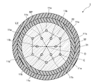
- FIG. 1 is a view showing a state of a multi-core fiber according to the first embodiment of the present invention.
- the multi-core fiber 1 of the present embodiment includes a plurality of cores 11a and 11b and an even number of 10 or more as a whole, and surrounds the outer peripheral surface of each of the cores 11a and 11b without any gaps.
- a clad 20, an inner protective layer 31 that covers the outer peripheral surface of the clad 20, and an outer protective layer 32 that covers the outer peripheral surface of the inner protective layer 31 are provided.
- FIG. 1 shows a case where there are 12 cores.
- each of the cores 11a and 11b has the same configuration.
- the refractive index of each of the cores 11a and 11b is higher than the refractive index of the cladding 20, and the cores 11a and 11b have a dopant such as germanium that increases the refractive index.
- the clad 20 is made of pure quartz, for example, the clad 20 is made of pure quartz, and when the cores 11a and 11b are made of pure quartz, for example, the clad 20 is made of quartz doped with a dopant such as fluorine that lowers the refractive index. Become.
- the cores 11a are arranged such that the centers of the respective cores 11a are positioned on the vertices C of the regular polygon RP indicated by the broken line with the reference point O of the clad 20 as the center. .
- the core 11a is arranged in a regular polygonal shape with the reference point O of the cladding 20 as the center.
- FIG. 1 shows a case where the total number of cores is 12, the number of cores 11a is 6, and the cores 11a are arranged in a regular hexagonal shape.
- the reference point O is the center point of the clad 20.
- the other core 11b is the remaining half of the cores other than the core 11a, and is disposed inside the regular polygon RP formed by the core 11a. That is, the core 11 a is disposed on the outer peripheral side of the clad 20, and the core 11 b is disposed on the inner peripheral side of the clad 20. Specifically, each core 11b is arranged such that its center is located on the vertical bisector LV of each side of the regular polygon RP.
- the cores 11b on the inner peripheral side are not located in the center of the clad 20, but are unevenly distributed on the outer peripheral side so that the outer sides of the regular polygon RP can be seen from between the cores 11a on the outer peripheral side. Neither core needs to be surrounded by many cores.
- FIG. 2 is a diagram for explaining a range in which the center of the core 11b on the inner peripheral side is located.
- a circle Ci passing through each vertex of the regular polygon RP and centering on the reference point O is indicated by a broken line
- each perpendicular bisector of two adjacent sides of the regular polygon RP is indicated by a broken line. They are shown as LVa and LVb, respectively.
- the magnitude of the angle formed by the straight line Lc connecting the vertex C of the regular polygon RP and the reference point O and the perpendicular bisector LVa is ⁇ n
- the multi-core fiber 1 including the core 11a and the core 11b is combined.
- n is the number of all cores in It becomes.
- an angle formed by the straight line Lc and the perpendicular bisector LVb is ⁇ n due to symmetry.
- the core 11b is centered on the intersection of the circle Ci and the perpendicular bisector LV. Is located.
- two core 11b shown in out view second core 11b is a circle Ci and the center at the intersection B 1 between the intersection A 1 and circle Ci and the vertical bisector LVb the perpendicular bisector LVa each It is arranged to be located.
- the core 11a and the core 11b are adjacent to each other.
- R be the size of the radius of the circle Ci
- ⁇ be the distance between the centers of adjacent cores 11a and 11b when the centers of all the cores 11a and 11b are arranged on the vertices of the same regular polygon.
- this inter-core distance ⁇ is used as a reference for the inter-core distance.
- the point A 2 is an intersection of the vertical bisector LVa and the side of the regular polygon RP
- the point B 2 is an intersection of the vertical bisector LVb and the side of the regular polygon RP.
- the point A 3 is a symmetric point with respect to the side of the regular polygon RP at the intersection A 1
- the point B 3 is a symmetric point with respect to the side of the regular polygon RP at the intersection B 1 . Accordingly, the distance between the point A 3 and the vertex C and the distance between the point B 3 and the vertex C are equal to the distance between the point A 1 and the vertex C and the distance between the point B 1 and the vertex C, and ⁇ .
- a point A 4 is a point on the perpendicular bisector LVa in the case where the acute angle formed by the line and the straight line Lc connecting the point and the vertex C of the perpendicular bisector LVa becomes 30 °
- the point B 4 is a point on the perpendicular bisector LVb in the case where the acute angle formed by the line and the straight line Lc connecting the point on the perpendicular bisector LVb and vertex C the 30 °.
- the point A 5 and the point B 5 are the point on the vertical bisector LVa and the vertical two when the both ends of the straight line having the length ⁇ perpendicular to the straight line Lc are located on the vertical bisectors LVa and LVb. It is a point on the bisector LVb.
- ⁇ 1 is expressed by the following formula (4).
- ⁇ 2 is expressed by the following formula (5).
- ⁇ 3 is expressed by the following formula (6).
- phi 4 are represented by the following formula (7).
- the core 11b when the core 11b is positioned on the outermost peripheral side, the distance between the distance and the point A 3 and the vertex C of the point A 1 and the vertex C are equal, and the distance between the point B 1 and the vertex C and the point B 3 and by paying attention to the distance between the vertex C are equal to the center distance between the core 11a and the core 11b is greater than ⁇ is centered reference than the point a 3 and the point B 3 cores 11b It only needs to be located on the point side. Further, if the center of the core 11b is too close to the reference point side, the center-to-center distance between the cores 11b becomes ⁇ or less. Therefore, in order to center distance between the core 11b is larger than ⁇ would center the core 11b has only to be positioned on the outer peripheral side than the point A 5 and point B 5.
- phi may be between the phi 3 and phi 4 may be on phi 4, may be between the phi 4 and phi 5.
- the core is arranged as in the present embodiment.
- Table 1 below shows the above-mentioned ⁇ n , R, A 3 B 3 , A 4 B 4 , ⁇ 3 , and ⁇ 5 in the multi-core fiber.
- Table 1 below shows the case where the total number of cores is 6 to 18.
- FIG. 3 is a diagram showing a bending radius and a fracture probability of an optical fiber made of quartz.
- FIG. 3 shows the cumulative failure probability for 20 years for each optical fiber cladding diameter when the optical fiber is wound 100 turns at each bending radius.
- the proof distortion was calculated as 1.5%.
- the diameter of an optical fiber used for communication is 125 ⁇ m.
- This optical fiber is a fiber that is resistant to bending, and a breaking probability when it is wound for 10 turns with a bending radius of 15 mm is required to be about 1.39 ⁇ 10 ⁇ 8 .
- FIG. 3 also shows the probability of breakage when an optical fiber having an outer diameter of the cladding of 125 ⁇ m is wound 10 turns at each bending radius.
- the reliability required for a communication optical fiber having an outer diameter of the clad larger than 125 ⁇ m is wound with 100 turns at a bending radius of 30 mm, the cumulative failure probability for 20 years is 1.39 ⁇ 10 ⁇ 8.
- the upper limit of the allowable outer diameter of the cladding is 230 ⁇ m. Therefore, if the outer diameter of the cladding is 230 ⁇ m or less, the reliability can be further increased.
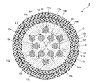
- FIG. 4 is a cross-sectional view showing a multicore fiber according to a second embodiment of the present invention.
- the multi-core fiber 2 of the present embodiment includes a plurality of core elements 10a and 10b, a core 11a is provided in each core element 10a, and a core 11b is provided in each core element 10b. In that respect, it differs from the multi-core fiber 1 of the first embodiment.
- the core element 10a includes a core 11a disposed in the same manner as the core 11a of the first embodiment, an inner cladding layer 12 that surrounds the outer peripheral surface of the core 11a, an outer peripheral surface of the inner cladding layer 12, and the outer peripheral surface is clad 20
- the core element 10b includes a core 11b arranged in the same manner as the core 11b of the first embodiment, an inner cladding layer 12 surrounding the outer peripheral surface of the core 11b, It has a low refractive index layer 13 that surrounds the outer peripheral surface of the inner cladding layer 12, and the outer peripheral surface is surrounded by the clad 20.
- the respective core elements 10a and 10b have the same configuration.
- each core 11a, 11b is arrange
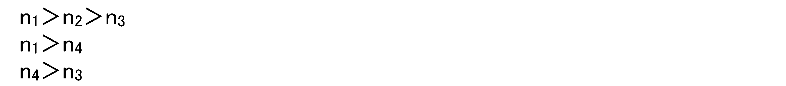
- the refractive index n 3 is further lower than the refractive index n 2 of the inner cladding layer 12.
- the refractive index n 4 of the clad 20 is set lower than the refractive index n 1 of the cores 11 a and 11 b and higher than the refractive index n 3 of the low refractive index layer 13.
- each refractive index n 1 to n 4 satisfies all of the following expressions. Therefore, when each core element 10a, 10b is viewed from the viewpoint of refractive index, each core element 10a, 10b has a trench structure.
- the refractive index n 3 of the low refractive index layer 13 is made smaller than the refractive index n 2 of the inner cladding layer 12 and the refractive index n 4 of the cladding 20, thereby confining light in the cores 11 a and 11 b. And the light propagating through the cores 11a and 11b can be prevented from leaking from the core elements 10a and 10b.
- the low refractive index layer 13 and the clad 20 having a low refractive index serve as a barrier, and crosstalk between adjacent cores can be further suppressed.
- the core element 10b on the inner peripheral side is unevenly arranged on the outer peripheral side so as to look into the outside of the regular polygon RP from between the core elements 10a on the outer peripheral side.
- any core element need not be surrounded by many core elements. Accordingly, it is possible to suppress an increase in the cutoff wavelength in any core element.
- FIG. 5 is a view showing a state of the multi-core fiber 3 according to the third embodiment of the present invention.
- the multi-core fiber 3 of the present embodiment includes core elements 15a arranged at the same positions as the core elements 10a instead of the core elements 10a in the second embodiment,
- This embodiment differs from the multi-core fiber 2 of the second embodiment in that a core element 15b is provided at the same position as each core element 10b instead of the core element 10b.
- each core element 15a and each core element 15b have the same structure.
- Each core element 15 a includes a core 11 a, an inner cladding layer 12 surrounding the outer peripheral surface of the core 11 a, and a low refractive index layer 14 surrounding the outer peripheral surface of the inner cladding layer 12 and surrounded by the cladding 20.
- Each core element 15b has a core 11b, an inner cladding layer 12 surrounding the outer peripheral surface of the core 11b, and a low refractive index layer 14 surrounding the outer peripheral surface of the inner cladding layer 12 and surrounded by the cladding 20. is doing.
- Each low-refractive index layer 14 is formed of a plurality of low-refractive index portions 17 made of the same material as the clad 20 and having a refractive index lower than that of the inner clad layer 12 so as to surround the inner clad layer 12.
- a plurality of circular holes are formed in the low refractive index layer 14, and these holes serve as the low refractive index portion 17.
- the refractive index of the low refractive index portion 17 is 1, which is lower than the refractive indexes of the inner cladding layer 12 and the cladding 20, so that the average of the low refractive index layer 14
- the refractive index is set lower than the refractive indexes of the inner cladding layer 12 and the cladding 20.
- the regions other than the low refractive index portion 17 of the low refractive index layer 14 are made of the same material as that of the inner cladding layer 12 and the clad 20 and thus have no boundary.
- the boundary is indicated by a broken line as a virtual line.
- the multi-core fiber 3 of the present embodiment the effect of confining light in the core 11 is increased, and it is possible to prevent light propagating through the cores 11a and 11b from leaking from the core elements 15a and 15b. Therefore, crosstalk between adjacent cores can be further suppressed. Also in this embodiment, as in the second embodiment, it is possible to prevent the cutoff wavelength from increasing in any core element.
- the multi-core fibers 1, 2 and 3 shown in FIGS. 1, 4 and 5 each have 12 cores as a whole, but the total number of cores is an even number of 10 or more as described above. It suffices that the number of cores is not limited to twelve. Further, in the multi-core fibers 1, 2, and 3, the refractive indexes and dimensions of the adjacent cores 11 a and 11 b, the core elements 10 a and 10 b, and the core elements 15 a and 15 b are not the same. Also good.
- Example 1 In the multi-core fiber of the present invention, in the case where the number of cores is 10, 12, 14, 16, and 18, the samples 1 to 20 having different conditions are used for ⁇ and inner circumference described in the above embodiment.
- the center-to-center distance ⁇ AB of the inner core, the center-to-center distance ⁇ AC of the inner and outer cores, the distance R from the center of the cladding to the center of the outer core, and the outer diameter D of the cladding were measured. .
- the distance (outermost cladding thickness) between the center of the core on the outer peripheral side and the outer peripheral surface of the cladding was set to 35 ⁇ m. The results are shown in Table 2 below.
- Example 2 Next, the multi-core fiber of the second embodiment was made as samples 26 to 28, and the multi-core fiber of the first embodiment was made as samples 29 to 31 under the conditions shown in Table 4 below. Then, the loss, the mode field diameter, and the effective core area are measured with the light having the wavelengths shown in Table 4, the cable cutoff wavelength, the zero dispersion wavelength, and the zero dispersion slope are measured, and the dispersion and bending radius is 7.5 mm. The bending loss and crosstalk were measured with light having the wavelengths shown in Table 4. Here, for optical characteristics other than the dimensions, the average values of all the cores are shown. The cable cut-off wavelength was not particularly long for the inner core.
- the multi-core fiber of the second embodiment can reduce crosstalk more than the multi-core fiber of the first embodiment.
- a multi-core fiber capable of suppressing crosstalk is provided, and can be favorably used for a communication cable or the like.
Abstract
Description

図1は、本発明の第1実施形態に係るマルチコアファイバの様子を示す図である。図1に示すように、本実施形態のマルチコアファイバ1は、それぞれ複数のコア11a,11bから成り全体で10以上の偶数個となるコアと、それぞれのコア11a,11bの外周面を隙間なく囲むクラッド20と、クラッド20の外周面を被覆する内側保護層31と、内側保護層31の外周面を被覆する外側保護層32と、を備える。図1では、コアが12個の場合が示されている。 (First embodiment)
FIG. 1 is a view showing a state of a multi-core fiber according to the first embodiment of the present invention. As shown in FIG. 1, the


次に、本発明の第2実施形態について図4を参照して詳細に説明する。なお、第1実施形態と同一又は同等の構成要素については、特に説明する場合を除き、同一の参照符号を付して重複する説明は省略する。 (Second Embodiment)
Next, a second embodiment of the present invention will be described in detail with reference to FIG. In addition, about the component which is the same as that of 1st Embodiment, or equivalent, except the case where it demonstrates especially, the same referential mark is attached | subjected and the overlapping description is abbreviate | omitted.
次に、本発明の第3実施形態について図5を参照して詳細に説明する。なお、第2実施形態と同一又は同等の構成要素については、特に説明する場合を除き、同一の参照符号を付して重複する説明は省略する。 (Third embodiment)
Next, a third embodiment of the present invention will be described in detail with reference to FIG. In addition, about the component which is the same as that of 2nd Embodiment, or equivalent, except the case where it demonstrates especially, the same referential mark is attached | subjected and the overlapping description is abbreviate | omitted.
本発明のマルチコアファイバにおいて、コアの数が10個,12個、14個、16個、18個の場合について、条件を互いに変えたサンプル1~20について、上記実施形態で説明したφ、内周側のコアの中心間距離ΛAB、内周側のコアと外周側のコアの中心間距離ΛAC、クラッドの中心から外周側のコアの中心までの距離R、クラッドの外径Dを計測した。なお、下記実施例では、外周側のコアの中心とクラッドの外周面との距離(最外クラッド厚)を35μmとした。この結果を下記表2に示す。
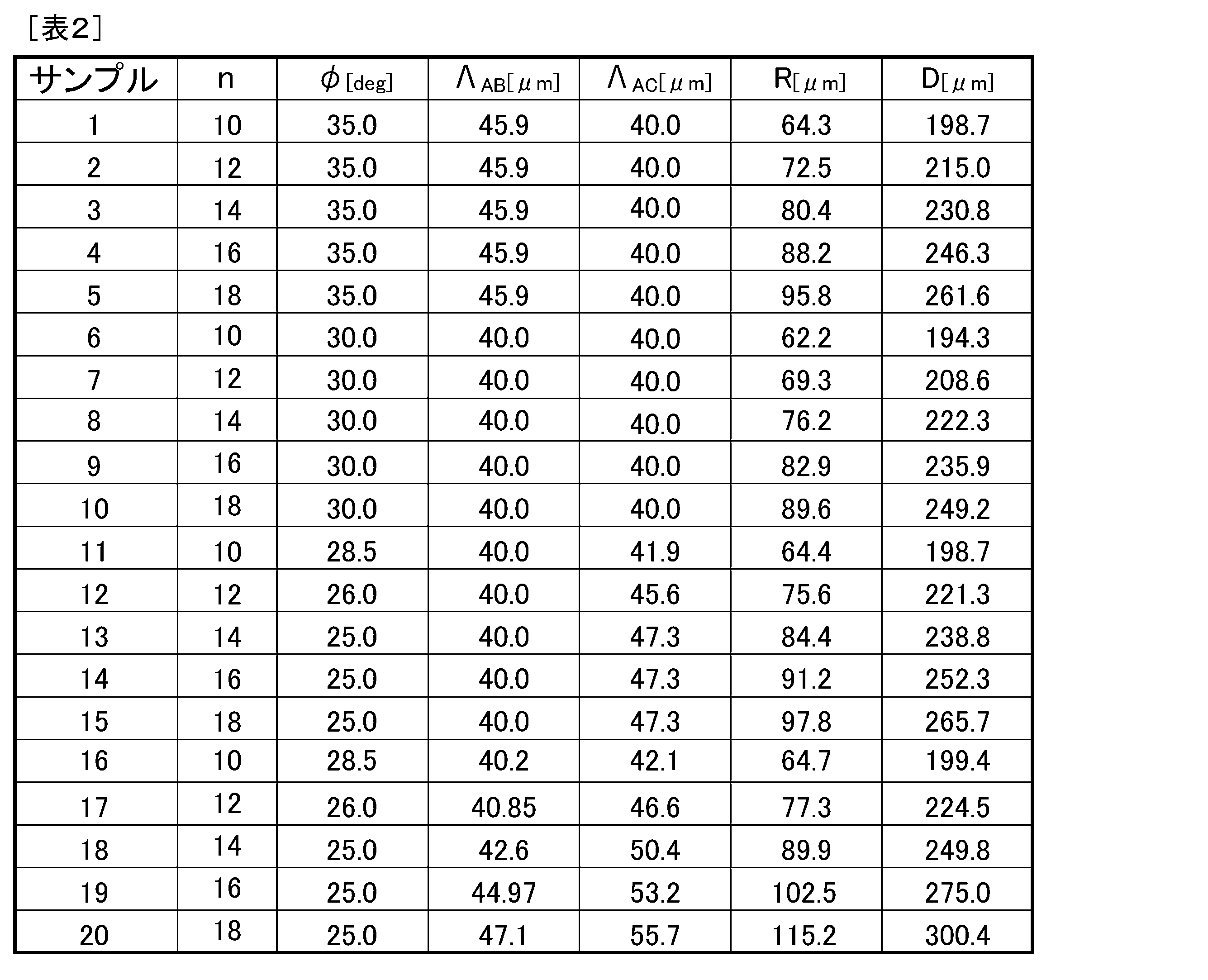
In the multi-core fiber of the present invention, in the case where the number of cores is 10, 12, 14, 16, and 18, the
次にコアの数が10個,12個、14個、16個、18個であり、全てのコアが正多角形状に配置される場合のマルチコアファイバをサンプル21~25として、互いに隣り合うコアの中心間距離を40μmとし、コアの中心とクラッドの外周面との距離(最外クラッド厚)を実施例1と同じく35μmとして、クラッドの中心からコアの中心までの距離R、クラッドの外径Dを計測した。この結果を表3に示す。

Next, when the number of cores is 10, 12, 14, 16, and 18 and all the cores are arranged in a regular polygon shape, samples 21 to 25 are used as samples of cores adjacent to each other. The distance between the centers is 40 μm, the distance between the center of the core and the outer peripheral surface of the clad (outermost clad thickness) is 35 μm, as in Example 1, the distance R from the center of the clad to the center of the core, and the outer diameter D of the clad Was measured. The results are shown in Table 3.
次に第2実施形態のマルチコアファイバをサンプル26~28として、第1実施形態のマルチコアファイバをサンプル29~31として、下記表4で示される条件で作製した。そして、損失、モードフィールド径、実効コア断面積について表4に記載の波長の光で測定をし、ケーブルカットオフ波長、ゼロ分散波長、ゼロ分散スロープについて測定をし、分散、曲げ半径7.5mmでの曲げ損失、クロストークについて表4に記載の波長の光で測定をした。ここで、寸法以外の光学特性については、全てのコアの平均値を示した。ケーブルカットオフ波長は、特に内側のコアが長いということはなかった。

Next, the multi-core fiber of the second embodiment was made as samples 26 to 28, and the multi-core fiber of the first embodiment was made as samples 29 to 31 under the conditions shown in Table 4 below. Then, the loss, the mode field diameter, and the effective core area are measured with the light having the wavelengths shown in Table 4, the cable cutoff wavelength, the zero dispersion wavelength, and the zero dispersion slope are measured, and the dispersion and bending radius is 7.5 mm. The bending loss and crosstalk were measured with light having the wavelengths shown in Table 4. Here, for optical characteristics other than the dimensions, the average values of all the cores are shown. The cable cut-off wavelength was not particularly long for the inner core.
10a,10b・・・コア要素
11a,11b・・・コア
12・・・内側クラッド層
13,14・・・低屈折率層
15a,15b・・・コア要素
17・・・低屈折率部
20・・・クラッド
31・・・内側保護層
32・・・外側保護層
C・・・頂点
Ci・・・円
Lc・・・直線
LV・・・垂直二等分線
O・・・基準点
RP・・・正多角形 1, 2, 3 ...
Claims (6)
- 10以上の偶数個のコアと、前記コアを囲むクラッドとを有するマルチコアファイバであって、
前記偶数個のコアのうち半数のコアは、前記クラッド内の基準点を中心とした正多角形の各頂点上に中心が位置するように配置され、
前記偶数個のコアのうち前記半数のコア以外の他のコアは、前記正多角形の内側において、前記正多角形の各辺のそれぞれの垂直二等分線上に中心が位置するように配置され、
前記偶数個のコアの数をnとし、前記半数のコアのうち着目するコアの中心と前記着目するコアと隣り合う前記他のコアの中心とを結ぶ線と、前記着目するコアの中心と前記基準点とを結ぶ線とがなす鋭角の大きさをφとする場合に下記式を満たす
ことを特徴とするマルチコアファイバ。
A multi-core fiber having an even number of cores of 10 or more and a clad surrounding the core,
Half of the even number of cores are arranged so that the center is located on each vertex of a regular polygon centered on a reference point in the cladding,
Of the even number of cores, the other cores other than the half of the cores are arranged inside the regular polygon so that the centers are located on the respective perpendicular bisectors of the sides of the regular polygon. ,
The number of the even number of cores is n, and a line connecting the center of the core of interest among the half of the cores and the center of the other core adjacent to the core of interest, and the center of the core of interest A multi-core fiber characterized by satisfying the following formula when the size of an acute angle formed by a line connecting a reference point is φ.
- それぞれの前記コアは、前記コアよりも屈折率が低い内側クラッド層と、前記クラッド及び前記内側クラッド層よりも平均屈折率が低く前記内側クラッド層を囲むと共に前記クラッドにより囲まれる低屈折率層と、により囲まれる
ことを特徴とする請求項1に記載のマルチコアファイバ。 Each of the cores includes an inner cladding layer having a refractive index lower than that of the core, a low refractive index layer having an average refractive index lower than that of the cladding and the inner cladding layer, and surrounding the inner cladding layer and surrounded by the cladding. The multi-core fiber according to claim 1, wherein the multi-core fiber is surrounded by. - 前記低屈折率層は、前記クラッド及び前記内側クラッド層よりも低い屈折率の材料から成る
ことを特徴とする請求項2に記載のマルチコアファイバ。 The multi-core fiber according to claim 2, wherein the low refractive index layer is made of a material having a lower refractive index than the clad and the inner clad layer. - それぞれの前記コアは純粋な石英から成る
ことを特徴とする請求項3に記載のマルチコアファイバ。 The multi-core fiber according to claim 3, wherein each of the cores is made of pure quartz. - 前記低屈折率層は、前記クラッドと同じ屈折率の材料中に前記内側クラッド層よりも屈折率が低い低屈折率部が、前記内側クラッド層を囲むように複数形成されて成ることを特徴とする請求項2に記載のマルチコアファイバ。 The low refractive index layer is formed by forming a plurality of low refractive index portions having a lower refractive index than the inner cladding layer in a material having the same refractive index as that of the cladding so as to surround the inner cladding layer. The multi-core fiber according to claim 2.
- 前記クラッドの外径は230μm以下である
ことを特徴とする請求項1~5のいずれか1項に記載のマルチコアファイバ。 6. The multi-core fiber according to claim 1, wherein an outer diameter of the clad is 230 μm or less.
Priority Applications (3)
| Application Number | Priority Date | Filing Date | Title |
|---|---|---|---|
| EP14757761.3A EP2963465B1 (en) | 2013-02-27 | 2014-02-27 | Multi-core fiber |
| JP2015503004A JPWO2014133057A1 (en) | 2013-02-27 | 2014-02-27 | Multi-core fiber |
| US14/770,570 US9400351B2 (en) | 2013-02-27 | 2014-02-27 | Multi-core fiber |
Applications Claiming Priority (2)
| Application Number | Priority Date | Filing Date | Title |
|---|---|---|---|
| JP2013-037809 | 2013-02-27 | ||
| JP2013037809 | 2013-02-27 |
Publications (1)
| Publication Number | Publication Date |
|---|---|
| WO2014133057A1 true WO2014133057A1 (en) | 2014-09-04 |
Family
ID=51428317
Family Applications (1)
| Application Number | Title | Priority Date | Filing Date |
|---|---|---|---|
| PCT/JP2014/054806 WO2014133057A1 (en) | 2013-02-27 | 2014-02-27 | Multi-core fiber |
Country Status (4)
| Country | Link |
|---|---|
| US (1) | US9400351B2 (en) |
| EP (1) | EP2963465B1 (en) |
| JP (1) | JPWO2014133057A1 (en) |
| WO (1) | WO2014133057A1 (en) |
Families Citing this family (8)
| Publication number | Priority date | Publication date | Assignee | Title |
|---|---|---|---|---|
| WO2015133407A1 (en) * | 2014-03-07 | 2015-09-11 | 株式会社フジクラ | Multi-core fiber |
| JP6050847B2 (en) * | 2015-02-12 | 2016-12-21 | 株式会社フジクラ | Multi-core fiber |
| EP4119995B1 (en) * | 2016-05-11 | 2024-05-01 | Intuitive Surgical Operations, Inc. | Redundant core in multicore optical fiber for safety |
| JP7316996B2 (en) * | 2018-02-28 | 2023-07-28 | 古河電気工業株式会社 | Multicore fiber, manufacturing method thereof, optical transmission system, and optical transmission method |
| WO2021188290A1 (en) * | 2020-03-19 | 2021-09-23 | Corning Incorporated | Multicore fiber with exterior cladding region |
| CN111999799B (en) * | 2020-09-18 | 2022-04-08 | 长飞光纤光缆股份有限公司 | Multi-core optical fiber |
| JP2022063072A (en) * | 2020-10-09 | 2022-04-21 | 住友電気工業株式会社 | Multi-core optical fiber and multi-core optical fiber cable |
| US20230204849A1 (en) * | 2021-12-28 | 2023-06-29 | Sterlite Technologies Limited | Trench assisted multi-core optical fiber with reduced crosstalk |
Citations (3)
| Publication number | Priority date | Publication date | Assignee | Title |
|---|---|---|---|---|
| JP2011180243A (en) * | 2010-02-26 | 2011-09-15 | Sumitomo Electric Ind Ltd | Multi-core optical fiber |
| JP2012181282A (en) * | 2011-02-28 | 2012-09-20 | Fujikura Ltd | Multi-core fiber |
| JP2013033865A (en) * | 2011-08-02 | 2013-02-14 | Mitsubishi Cable Ind Ltd | Optical fiber and manufacturing method of optical fiber |
Family Cites Families (5)
| Publication number | Priority date | Publication date | Assignee | Title |
|---|---|---|---|---|
| WO2011024808A1 (en) * | 2009-08-28 | 2011-03-03 | 株式会社フジクラ | Multi-core fiber |
| JP5595888B2 (en) * | 2010-12-09 | 2014-09-24 | 株式会社フジクラ | Multi-core fiber |
| JP2012168453A (en) * | 2011-02-16 | 2012-09-06 | Hitachi Cable Ltd | Multi-core optical fiber, method of manufacturing multi-core optical fiber, and method of interconnecting multi-core optical fibers |
| JP5819682B2 (en) * | 2011-09-05 | 2015-11-24 | 株式会社フジクラ | Multicore fiber for communication |
| US20150205053A1 (en) * | 2012-08-01 | 2015-07-23 | Konica Minolta, Inc. | Multi-core Fiber Connection Member, Structure for Connecting Multi-Core Fibers, and Method for Connecting Multi-Core Fibers |
-
2014
- 2014-02-27 WO PCT/JP2014/054806 patent/WO2014133057A1/en active Application Filing
- 2014-02-27 JP JP2015503004A patent/JPWO2014133057A1/en active Pending
- 2014-02-27 EP EP14757761.3A patent/EP2963465B1/en active Active
- 2014-02-27 US US14/770,570 patent/US9400351B2/en active Active
Patent Citations (3)
| Publication number | Priority date | Publication date | Assignee | Title |
|---|---|---|---|---|
| JP2011180243A (en) * | 2010-02-26 | 2011-09-15 | Sumitomo Electric Ind Ltd | Multi-core optical fiber |
| JP2012181282A (en) * | 2011-02-28 | 2012-09-20 | Fujikura Ltd | Multi-core fiber |
| JP2013033865A (en) * | 2011-08-02 | 2013-02-14 | Mitsubishi Cable Ind Ltd | Optical fiber and manufacturing method of optical fiber |
Non-Patent Citations (4)
| Title |
|---|
| K. IMAMURA ET AL.: "19-core multi core fiber to realize high density space division multiplexing transmission", PROC. IEEE PHOTON. SOC. SUMMER TOPICAL MEETING 2012, 2012 |
| K. TAKENAGA ET AL.: "Reduction of crosstalk by quasi-homogeneous solid multi-core fiber", OFC 2010, OWK, vol. 7, 2010 |
| K. TAKENAGA ET AL.: "Reduction of crosstalk by trench-assisted multi-core fiber", OFC 2011, OWJ4, 2011 |
| KAZUHIRO OKUYAMA ET AL.: "Investigation on Circularly Arranged Multi- Core Fibers for Increasing the Number of Cores", THE INSTITUTE OF ELECTRONICS, INFORMATION AND COMMUNICATION ENGINEERS SOGO TAIKAI KOEN RONBUNSHU, vol. 2, 6 March 2012 (2012-03-06), pages 547, XP008171841 * |
Also Published As
| Publication number | Publication date |
|---|---|
| JPWO2014133057A1 (en) | 2017-02-02 |
| US9400351B2 (en) | 2016-07-26 |
| US20160004009A1 (en) | 2016-01-07 |
| EP2963465A4 (en) | 2016-11-02 |
| EP2963465B1 (en) | 2021-03-17 |
| EP2963465A1 (en) | 2016-01-06 |
Similar Documents
| Publication | Publication Date | Title |
|---|---|---|
| WO2014133057A1 (en) | Multi-core fiber | |
| JP5916525B2 (en) | Multi-core fiber | |
| JP5267481B2 (en) | Multi-core optical fiber | |
| JP5819682B2 (en) | Multicore fiber for communication | |
| JP6722271B2 (en) | Multi-core fiber | |
| JP6177994B2 (en) | Multi-core fiber | |
| US8805146B2 (en) | Multicore optical fiber | |
| JP5468711B2 (en) | Multi-core fiber | |
| JP5855351B2 (en) | Multi-core fiber | |
| JP6050847B2 (en) | Multi-core fiber | |
| JP5860024B2 (en) | Multi-core fiber | |
| JP5522696B2 (en) | 4-core single-mode optical fiber and optical cable | |
| JP2015212791A (en) | Multicore fiber | |
| JP5808767B2 (en) | Multi-core fiber | |
| WO2015001990A1 (en) | Multi-core optical fiber and multi-core optical fiber cable | |
| WO2017130487A1 (en) | Multicore fiber | |
| JP6096268B2 (en) | Multi-core fiber | |
| WO2018150867A1 (en) | Multicore fiber, and multicore fiber tape using same | |
| JP5990616B2 (en) | Multicore fiber for communication |
Legal Events
| Date | Code | Title | Description |
|---|---|---|---|
| 121 | Ep: the epo has been informed by wipo that ep was designated in this application |
Ref document number: 14757761 Country of ref document: EP Kind code of ref document: A1 |
|
| ENP | Entry into the national phase |
Ref document number: 2015503004 Country of ref document: JP Kind code of ref document: A |
|
| WWE | Wipo information: entry into national phase |
Ref document number: 14770570 Country of ref document: US |
|
| NENP | Non-entry into the national phase |
Ref country code: DE |
|
| WWE | Wipo information: entry into national phase |
Ref document number: 2014757761 Country of ref document: EP |