WO2014132741A1 - 画像処理装置及び内視鏡システムの作動方法 - Google Patents
画像処理装置及び内視鏡システムの作動方法 Download PDFInfo
- Publication number
- WO2014132741A1 WO2014132741A1 PCT/JP2014/052247 JP2014052247W WO2014132741A1 WO 2014132741 A1 WO2014132741 A1 WO 2014132741A1 JP 2014052247 W JP2014052247 W JP 2014052247W WO 2014132741 A1 WO2014132741 A1 WO 2014132741A1
- Authority
- WO
- WIPO (PCT)
- Prior art keywords
- image
- display control
- unit
- signal
- processing apparatus
- Prior art date
- Legal status (The legal status is an assumption and is not a legal conclusion. Google has not performed a legal analysis and makes no representation as to the accuracy of the status listed.)
- Ceased
Links
Images














Classifications
-
- G—PHYSICS
- G02—OPTICS
- G02B—OPTICAL ELEMENTS, SYSTEMS OR APPARATUS
- G02B23/00—Telescopes, e.g. binoculars; Periscopes; Instruments for viewing the inside of hollow bodies; Viewfinders; Optical aiming or sighting devices
- G02B23/24—Instruments or systems for viewing the inside of hollow bodies, e.g. fibrescopes
- G02B23/2476—Non-optical details, e.g. housings, mountings, supports
- G02B23/2484—Arrangements in relation to a camera or imaging device
-
- A—HUMAN NECESSITIES
- A61—MEDICAL OR VETERINARY SCIENCE; HYGIENE
- A61B—DIAGNOSIS; SURGERY; IDENTIFICATION
- A61B1/00—Instruments for performing medical examinations of the interior of cavities or tubes of the body by visual or photographical inspection, e.g. endoscopes; Illuminating arrangements therefor
- A61B1/00002—Operational features of endoscopes
- A61B1/00004—Operational features of endoscopes characterised by electronic signal processing
- A61B1/00009—Operational features of endoscopes characterised by electronic signal processing of image signals during a use of endoscope
- A61B1/000094—Operational features of endoscopes characterised by electronic signal processing of image signals during a use of endoscope extracting biological structures
-
- A—HUMAN NECESSITIES
- A61—MEDICAL OR VETERINARY SCIENCE; HYGIENE
- A61B—DIAGNOSIS; SURGERY; IDENTIFICATION
- A61B1/00—Instruments for performing medical examinations of the interior of cavities or tubes of the body by visual or photographical inspection, e.g. endoscopes; Illuminating arrangements therefor
- A61B1/00002—Operational features of endoscopes
- A61B1/00043—Operational features of endoscopes provided with output arrangements
- A61B1/00045—Display arrangement
- A61B1/0005—Display arrangement combining images e.g. side-by-side, superimposed or tiled
-
- A—HUMAN NECESSITIES
- A61—MEDICAL OR VETERINARY SCIENCE; HYGIENE
- A61B—DIAGNOSIS; SURGERY; IDENTIFICATION
- A61B1/00—Instruments for performing medical examinations of the interior of cavities or tubes of the body by visual or photographical inspection, e.g. endoscopes; Illuminating arrangements therefor
- A61B1/04—Instruments for performing medical examinations of the interior of cavities or tubes of the body by visual or photographical inspection, e.g. endoscopes; Illuminating arrangements therefor combined with photographic or television appliances
- A61B1/044—Instruments for performing medical examinations of the interior of cavities or tubes of the body by visual or photographical inspection, e.g. endoscopes; Illuminating arrangements therefor combined with photographic or television appliances for absorption imaging
-
- G—PHYSICS
- G02—OPTICS
- G02B—OPTICAL ELEMENTS, SYSTEMS OR APPARATUS
- G02B23/00—Telescopes, e.g. binoculars; Periscopes; Instruments for viewing the inside of hollow bodies; Viewfinders; Optical aiming or sighting devices
- G02B23/24—Instruments or systems for viewing the inside of hollow bodies, e.g. fibrescopes
- G02B23/26—Instruments or systems for viewing the inside of hollow bodies, e.g. fibrescopes using light guides
-
- H—ELECTRICITY
- H04—ELECTRIC COMMUNICATION TECHNIQUE
- H04N—PICTORIAL COMMUNICATION, e.g. TELEVISION
- H04N23/00—Cameras or camera modules comprising electronic image sensors; Control thereof
- H04N23/10—Cameras or camera modules comprising electronic image sensors; Control thereof for generating image signals from different wavelengths
-
- H—ELECTRICITY
- H04—ELECTRIC COMMUNICATION TECHNIQUE
- H04N—PICTORIAL COMMUNICATION, e.g. TELEVISION
- H04N23/00—Cameras or camera modules comprising electronic image sensors; Control thereof
- H04N23/50—Constructional details
- H04N23/555—Constructional details for picking-up images in sites, inaccessible due to their dimensions or hazardous conditions, e.g. endoscopes or borescopes
-
- H—ELECTRICITY
- H04—ELECTRIC COMMUNICATION TECHNIQUE
- H04N—PICTORIAL COMMUNICATION, e.g. TELEVISION
- H04N23/00—Cameras or camera modules comprising electronic image sensors; Control thereof
- H04N23/56—Cameras or camera modules comprising electronic image sensors; Control thereof provided with illuminating means
-
- H—ELECTRICITY
- H04—ELECTRIC COMMUNICATION TECHNIQUE
- H04N—PICTORIAL COMMUNICATION, e.g. TELEVISION
- H04N23/00—Cameras or camera modules comprising electronic image sensors; Control thereof
- H04N23/60—Control of cameras or camera modules
- H04N23/63—Control of cameras or camera modules by using electronic viewfinders
- H04N23/631—Graphical user interfaces [GUI] specially adapted for controlling image capture or setting capture parameters
-
- H—ELECTRICITY
- H04—ELECTRIC COMMUNICATION TECHNIQUE
- H04N—PICTORIAL COMMUNICATION, e.g. TELEVISION
- H04N5/00—Details of television systems
- H04N5/222—Studio circuitry; Studio devices; Studio equipment
- H04N5/262—Studio circuits, e.g. for mixing, switching-over, change of character of image, other special effects ; Cameras specially adapted for the electronic generation of special effects
- H04N5/2628—Alteration of picture size, shape, position or orientation, e.g. zooming, rotation, rolling, perspective, translation
-
- H—ELECTRICITY
- H04—ELECTRIC COMMUNICATION TECHNIQUE
- H04N—PICTORIAL COMMUNICATION, e.g. TELEVISION
- H04N5/00—Details of television systems
- H04N5/222—Studio circuitry; Studio devices; Studio equipment
- H04N5/262—Studio circuits, e.g. for mixing, switching-over, change of character of image, other special effects ; Cameras specially adapted for the electronic generation of special effects
- H04N5/265—Mixing
-
- H—ELECTRICITY
- H04—ELECTRIC COMMUNICATION TECHNIQUE
- H04N—PICTORIAL COMMUNICATION, e.g. TELEVISION
- H04N9/00—Details of colour television systems
- H04N9/79—Processing of colour television signals in connection with recording
- H04N9/7908—Suppression of interfering signals at the reproducing side, e.g. noise
Definitions
- the present invention relates to an image processing apparatus for performing a diagnosis by paying attention to a gland duct structure and a fine blood vessel, and an operation method of an endoscope system.
- an endoscope system including a light source device, an electronic endoscope, and a processor device
- detection of such lesions is also possible.
- zooming in a zooming lens is used to enlarge and examine the possible lesion site, and magnified observation is performed.
- VS classification has been performed in which a diagnosis is made by paying attention to a fine mucosal structure.
- Patent Document 1 describes the selective emphasis / suppression of surface blood vessels and deep blood vessels, but does not explain the selective emphasis / suppression of microvessels and microstructures.
- Patent Document 2 describes a filtering process that can emphasize both the fine structure and the fine blood vessel, the filtering process of Patent Document 2 does not selectively enhance / suppress the fine blood vessel and the fine structure. Can not.
- the present invention provides an image processing apparatus capable of generating an endoscopic image in which one structure does not hinder the visibility of the other structure even when the microvessel and the fine structure are independently diagnosed.
- An object of the present invention is to provide a method for operating an endoscope system.
- an image processing apparatus of the present invention includes an image signal generation unit, a base image generation unit, a structure extraction image generation unit, a display control image generation unit, and an image synthesis unit.
- the image signal generation unit images the mucosal surface and generates a plurality of color image signals.
- the base image generation unit generates a base image based on a plurality of color image signals.
- the structure extraction image generation unit performs a first frequency component extraction process for extracting a first frequency component on a short wavelength image signal including a short wavelength component from among a plurality of color image signals.
- a first structure extracted image signal is generated by extracting pixels having the first structure.
- the display control image generation unit generates a display control image used for display control of the first structure based on the first structure extraction image signal.
- the image combining unit combines the base image and the display control image to generate a display control image in which the display of the first structure is controlled.
- the short wavelength image signal is preferably a B image signal containing a blue component.
- the B image signal is preferably a blue narrowband image signal.
- a narrow-band light source unit that emits blue narrow-band light is provided, and the blue narrow-band image signal is preferably obtained by imaging the mucosal surface illuminated with blue narrow-band light in the image signal generation unit.
- a spectral calculation unit that performs spectral calculation based on the image signals of a plurality of colors is provided, and the blue narrow-band image signal is obtained by spectral calculation.
- a magnifying means for magnifying the mucosal surface is provided, and the short wavelength image signal is obtained at the time of magnification observation using the magnifying means.
- the structure extraction image generation unit extracts the first structure pixel having a positive signal value and the second structure pixel having a negative signal value by performing a first frequency component extraction process on the short wavelength image signal.
- the first and second structure extraction image signals are generated.
- the display control image generation unit preferably generates a display control image used for display control of the first structure or the second structure based on the first and second structure extraction image signals.
- the image composition unit preferably synthesizes the base image and the display control image to generate a display control image in which the display of the first structure or the second structure is controlled.
- the display control image generation unit outputs a display control image in which the pixels of the first or second structure have a value corresponding to the display control amount in response to input of the first and second structure extraction image signals. It is preferable that It is preferable that the conversion unit includes a first conversion unit that outputs a display control image having a positive value corresponding to the enhancement degree when the pixel of the first structure emphasizes the display of the first structure. The conversion unit preferably includes a second conversion unit that outputs a display control image in which the pixels of the first structure have a negative value corresponding to the degree of suppression when the display of the first structure is suppressed.
- the conversion unit preferably includes a third conversion unit that outputs a display control image having a negative value corresponding to the degree of enhancement when the second structure pixel is emphasized.
- the conversion unit preferably includes a fourth conversion unit that outputs a display control image having a positive value corresponding to the degree of suppression of the pixels of the second structure when suppressing the display of the second structure.
- the conversion unit emphasizes both the first structure and the second structure and makes the first structure and the second structure have different visibility, the pixel of the first structure has a positive value, and the pixel of the second structure It is preferable to have a specific conversion unit that outputs a display control image having a negative value and different values of the first structure pixel and the second structure pixel.
- a determination unit that determines the value of each pixel of the first and second structure extraction image signals, and a pixel that is determined to have a positive or negative value by the determination unit among the first and second structure extraction image signals It is preferable to include a gain processing unit that generates a display control image by performing gain processing according to the display control amount of the first or second structure.
- the gain processing unit emphasizes both the first and second structures, and when the visibility of the first structure and the second structure is made different, the pixel determined to have a positive value by the determination unit and the negative value It is preferable to perform gain processing for emphasis having different emphasis levels on pixels determined to have.
- the structure extraction image generation unit performs the first frequency component extraction process on the short wavelength image signal, thereby the first structure pixel having a positive signal value and the second structure pixel having a negative signal value.
- the first and second structure extraction image signals are extracted, and the display control image generation unit generates one specific structure of the first structure or the second structure based on the first and second structure extraction image signals.
- the display control image used for emphasizing the display is generated, and the image synthesis unit synthesizes the base image on which the suppression process has been performed and the display control image to display the specific structure of the first and second structures.
- a display control image is generated that emphasizes and suppresses the display of the other structure.
- the first structure is a gland duct structure and the second structure is a microvessel.
- the operating method of the endoscope system includes an image signal generation step, a base image generation step, a structure extraction image generation step, a display control image generation step, and an image synthesis step.
- the image signal generation step the image signal generation unit images the mucosal surface and generates a plurality of color image signals.
- the base image generation step the base image generation unit generates a base image based on the image signals of a plurality of colors.
- the structure extraction image generation unit performs a first frequency component extraction process for extracting a first frequency component on a short wavelength image signal including a short wavelength component from among a plurality of color image signals.
- a first structure extraction image signal is generated by extracting pixels of the first structure having a positive signal value.
- the display control image generation unit generates a display control image used for display control of the first structure based on the first structure extraction image signal.
- the image composition step the image composition unit synthesizes the base image and the display control image to generate a display control image in which the display of the first structure is controlled.
- an endoscopic image in which one of the fine blood vessel and the fine structure does not hinder the visibility of the other structure even when the fine blood vessel and the fine structure are independently diagnosed. Can be generated.
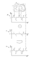
- A) is a graph which shows the luminance distribution in the predetermined line of Bch of B image signal
- B is a graph which shows distribution of the signal value in the structure extraction image signal after a frequency filtering process.
- the endoscope system 10 includes an endoscope 12, a light source device 14, a processor device 16, a monitor 18, and a console 20.
- the endoscope 12 is optically connected to the light source device 14 and electrically connected to the processor device 16.
- the endoscope 12 has an insertion portion 21 to be inserted into a specimen, an operation portion 22 provided at a proximal end portion of the insertion portion, a bending portion 23 and a distal end portion 24 provided on the distal end side of the insertion portion 21. is doing.
- the angle knob 22a of the operation unit 22 By operating the angle knob 22a of the operation unit 22, the bending unit 23 performs a bending operation. With this bending operation, the tip 24 is directed in a desired direction.
- the operation unit 22 is provided with a mode switching SW 22b and a zoom operation unit 22c.
- the mode switching SW 22b is used for switching operation between two types of modes, a normal observation mode and a special observation mode.
- the normal observation mode is an observation mode using white light, and is mainly used for screening or the like.
- the special observation mode is an observation mode using special light with a bluish color, and is mainly used for magnified observation or the like.
- the zoom operation unit 22c is used for a zoom operation for driving the zooming lens 47 (see FIG. 2) in the endoscope 12 to enlarge the specimen.
- the processor device 16 is electrically connected to the monitor 18 and the console 20.
- the monitor 18 outputs and displays image information and the like.
- the console 20 functions as a UI (user interface) that receives input operations such as function settings.
- the processor device 16 may be connected to an external recording unit (not shown) for recording image information and the like.
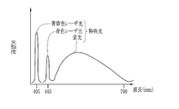
- the light source unit 14 includes a blue laser light source (445LD) 34 that emits blue laser light having a center wavelength of 445 nm and a blue-violet laser light source (405LD) 36 that emits blue-violet laser light having a center wavelength of 405 nm. It is provided as a light source. Light emission from the semiconductor light emitting elements of the light sources 34 and 36 is individually controlled by the light source control unit 40, and the light quantity ratio between the emitted light of the blue laser light source 34 and the emitted light of the blue-violet laser light source 36 is freely changeable. It has become.
- the light source control unit 40 drives only the blue laser light source 34 in the normal observation mode.
- the light source control unit 40 drives both the blue laser light source 34 and the blue-violet laser light 36 and sets the emission ratio of the blue-violet laser light to the emission ratio of the blue laser light. It is controlled to become larger than. Note that either or both of the blue laser light source 34 and the blue-violet laser light source 36 constitute a narrow-band light source unit of the present invention.
- the half-value width of the blue laser beam or the blue-violet laser beam is preferably about ⁇ 10 nm.
- the blue-violet laser light 36 may be driven. However, in this case, it is preferable to keep the emission intensity of the blue-violet laser light 36 low.
- a broad area type InGaN laser diode can be used, and an InGaNAs laser diode or a GaNAs laser diode can also be used.
- a light-emitting body such as a light-emitting diode may be used as the light source.
- the laser light emitted from each of the light sources 34 and 36 is incident on a light guide (LG) 41 through optical members (all not shown) such as a condenser lens, an optical fiber, and a multiplexer.
- the light guide 41 is built in the endoscope 12 and a universal cord (a cord for connecting the light source device 14 and the endoscope 12).
- a blue laser beam having a central wavelength of 445 nm or a blue-violet laser having a central wavelength of 405 nm is propagated to the distal end portion 24 of the endoscope 12 through the light guide 41.
- a multimode fiber can be used as the light guide 41.
- a thin fiber cable having a core diameter of 105 ⁇ m, a cladding diameter of 125 ⁇ m, and a diameter including a protective layer serving as an outer shell of ⁇ 0.3 to 0.5 mm can be used.
- the distal end portion 24 of the endoscope has an illumination optical system 24a and an imaging optical system 24b.
- the illumination optical system 24 a is provided with a phosphor 44 on which blue laser light having a central wavelength of 445 nm or a blue-violet laser having a central wavelength of 405 nm from the light guide 41 is incident, and an illumination lens 45. Fluorescence is emitted from the phosphor 44 by irradiating the phosphor 44 with blue laser light. Some of the blue laser light passes through the phosphor 44 as it is. The blue-violet laser light is transmitted without exciting the phosphor 44. The light emitted from the phosphor 44 is irradiated into the specimen through the illumination lens 45.
- the blue laser light and the fluorescence excited and emitted from the phosphor 44 are combined by the blue laser light.
- White light is irradiated into the specimen.
- the special observation mode since both blue-violet laser light and blue laser light are incident on the phosphor 44, blue-violet laser light, blue laser light, and fluorescence excited and emitted from the phosphor 44 by the blue laser light are emitted.
- the combined special light is irradiated into the specimen.
- the emission ratio of the blue-violet laser light is larger than the emission ratio of the blue laser light, so that the special light contains a large amount of blue components and the wavelength range covers almost the entire visible light range. ing.
- the phosphor 44 absorbs a part of the blue laser light and emits a plurality of kinds of phosphors that emit green to yellow light (for example, a YAG phosphor or a phosphor such as BAM (BaMgAl 10 O 17 )). It is preferable to use what is comprised including. If a semiconductor light emitting device is used as an excitation light source for the phosphor 44 as in this configuration example, high intensity white light can be obtained with high luminous efficiency, and the intensity of white light can be easily adjusted, and the color of white light can be easily adjusted. Changes in temperature and chromaticity can be kept small.
- the imaging optical system 24b of the endoscope 12 includes an objective lens 46, a zooming lens 47, and an image sensor 48. Reflected light from the specimen enters the image sensor 48 via the objective lens 46 and the zooming lens 47. As a result, a reflected image of the specimen is formed on the image sensor 48.
- the zooming lens 47 moves between the tele end and the wide end by operating the zoom operation unit 22c. When the zooming lens 47 moves to the wide end side, the reflected image of the specimen is reduced, while when the zooming lens 47 moves to the tele end side, the reflected image of the specimen is enlarged.
- the image sensor 48 is a color image sensor, which captures a reflection image of a specimen and outputs an image signal.
- the image sensor 48 is preferably a CCD (Charge-Coupled Device) image sensor, a CMOS (Complementary Metal-Oxide Semiconductor) image sensor, or the like.
- the image sensor used in the present invention is a so-called RGB color image sensor having an RGB filter on the imaging surface in order to obtain image signals of three colors of R (red), G (green), and B (blue).
- a so-called complementary color image sensor provided with color filters of C (cyan), M (magenta), Y (yellow), and G (green) on the imaging surface may be used.
- RGB three-color image signals can be obtained by color conversion from four CMYG image signals.
- any one of the endoscope 12, the light source device 14, and the processor device 16 needs to include color conversion means for performing color conversion from the CMYG four-color image signal to the RGB three-color image signal. is there.
- the image signal output from the image sensor 48 is transmitted to the CDS / AGC circuit 50.
- the CDS / AGC circuit 50 performs correlated double sampling (CDS) and automatic gain control (AGC) on an image signal which is an analog signal.
- CDS correlated double sampling
- AGC automatic gain control
- the image signal that has passed through the CDS / AGC circuit 50 is converted into a digital image signal by an A / D converter (A / D converter) 52.
- a / D converted digital image signal is input to the processor device 16.
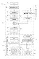
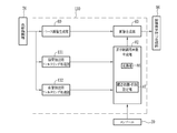
- the processor device 16 includes a receiving unit 54, an image processing switching unit 60, a normal light image processing unit 62, a special light image processing unit 64, and an image display signal generation unit 66.
- the receiving unit 54 receives a digital image signal from the endoscope 12.
- the receiving unit 54 includes a DSP (Digital Signal Processor) 56 and a noise removing unit 58.
- the DSP 56 performs gamma correction and color correction processing on the digital image signal.
- the noise removing unit 58 removes noise from the digital image signal by performing noise removal processing (for example, a moving average method, a median filter method, etc.) on the digital image signal subjected to gamma correction or the like by the DSP 56.
- the digital image signal from which noise has been removed is transmitted to the image processing switching unit 60.
- the image processing switching unit 60 transmits a digital image signal to the normal light image processing unit 62 when the mode switching SW 22b is set to the normal observation mode, and when set to the special observation mode, the digital processing is performed.
- the image signal is transmitted to the special light image processing unit 64.
- the digital image signal before image processing by the normal light image processing unit 62 and the special light image processing unit 64 is referred to as an image signal, and the digital image signal after the image processing is referred to as image data. I will decide.
- the normal light image processing unit 62 includes a color conversion unit 68, a color enhancement unit 70, and a structure enhancement unit 72.
- the color conversion unit 68 assigns the input RGB 3-channel digital image signals to R image data, G image data, and B image data, respectively. These RGB image data are further subjected to color conversion processing such as 3 ⁇ 3 matrix processing, gradation conversion processing, and three-dimensional LUT processing, and converted to color-converted RGB image data.
- the color enhancement unit 70 performs various color enhancement processes on the color-converted RGB image data.
- the structure enhancement unit 72 performs structure enhancement processing such as sharpness and contour enhancement on the color enhancement processed RGB image data.
- the RGB image data subjected to the structure enhancement processing by the structure enhancement unit 72 is input from the normal light image processing unit 62 to the image display signal generation unit 66 as a normal light image.
- the special light image processing unit 64 includes a color enhancement unit 76 and a structure enhancement / suppression unit 78.
- the color enhancement unit 76 performs various color enhancement processes on the input RGB three-channel digital image signal to generate a color-enhanced RGB image signal.
- the structure emphasis / suppression unit 78 generates a display control image by performing structure emphasis / suppression processing for emphasizing / suppressing a gland duct structure or a blood vessel with respect to the RGB image signal subjected to the color enhancement process.
- the display control image subjected to the structure enhancement / suppression processing by the structure enhancement / suppression unit 78 is input from the special light image processing unit 64 to the image display signal generation unit 66 as a special light image.
- the structure enhancement / suppression unit 78 includes a base image generation unit 80, a frequency filtering processing unit 81, a display control image generation unit 82, and an image synthesis unit 83.
- the base image generation unit 80 assigns the G image signal to the R image data and assigns the B image signal to the G image data and the B image data among the RGB image signals subjected to the color enhancement processing. These RGB image data become a base image.
- the B image signal is allocated to the B image data, but the B image signal is allocated to the G image data instead of the G image signal.
- the R image data is not the R image signal but the G image signal. Since the image signal is assigned, the base image is a pseudo color image.
- the base image generation unit may generate a white base image that is not a pseudo color by allocating RGB image signals to RGB image data, as in the color conversion unit 68.
- the frequency filtering processing unit 81 performs a frequency filtering process for extracting the frequency band component corresponding to the gland duct structure and the fine blood vessel in the mucous membrane surface layer on the color-enhanced B image signal.
- the gland duct structure S (Structure) extracted by the frequency filtering process is a marginal part that appears to be white (the gland duct includes a gland duct opening in addition to the marginal part).
- the B image signal corresponds to a blue component such as a blue-violet laser beam and a blue laser beam that can apply a structure enhancement effect to a gland duct structure or a fine blood vessel. This is because it is a signal.
- the duct structure S (Structure) is diffusely reflected by light of blue components such as blue-violet laser light and blue laser light, and therefore shines brighter than the mucous membrane on the B image signal 84.
- blue-violet laser light and blue laser light are highly linear light, unlike blue narrow-band light obtained by wavelength-separating broadband light such as xenon light. Reach deep. Due to this effect, the ductal structure S shines brighter.
- the fine blood vessel V (Vascular) absorbs blue component light having a high hemoglobin absorption coefficient, such as blue-violet laser light and blue laser light, among special light. It is also dark.
- the pixel of the gland duct structure S has an up edge where the signal value is “positive”, and the pixel of the microvessel V is It is a down edge where the signal value becomes “negative”. Further, the mucous membrane M (Mucous membrane) in the structure extraction image signal 85 has almost no change in luminance value, so the signal value is almost “0”.
- the B image signal 84 represents the luminance value of each pixel on the line 84a
- the structure extraction image signal 85 represents the signal value of each pixel on the line 84a (FIGS. 11 to 13). The same).
- the signal value is “0”, a value including a positive value and a negative value
- the luminance value is “0”, a value including a positive value.
- the display control image generation unit 82 generates a display control image for use in emphasis / suppression / display maintenance of a gland duct structure or a fine blood vessel from the structure extraction image signal.
- the display control image generation unit 82 inputs a structure extraction image signal and outputs a display control image, and sets an emphasis / suppression condition and controls the conversion unit according to the set emphasis / suppression condition.
- a structure enhancement / suppression setting unit 87 (see FIG. 4).
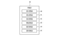
- the conversion unit 86 includes a first conversion unit 90, a second conversion unit 91, a third conversion unit 92, a fourth conversion unit 93, a fifth conversion unit 94, and a sixth conversion unit. And a display control image having a value corresponding to a display control amount such as a degree of enhancement or suppression of a gland duct structure or a fine blood vessel in response to the input of the structure extraction image signal.
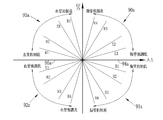
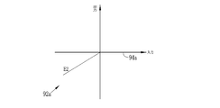
- the first conversion unit 90 is used when emphasizing the gland duct structure, and outputs a value according to the input / output relationship 90a shown in FIG. 7 in response to the input of the structure extraction image signal. Since the input / output relationship 90a is defined with a positive slope, a positive value is output in response to a positive value input.
- the gland duct structure By adding this output positive value to the gland duct structure on the base image, the gland duct structure brighter than the mucous membrane becomes brighter and the contrast between the mucous membrane and the gland duct structure is improved. Thereby, a duct emphasis effect is obtained.
- input / output relationships corresponding to the four first to fourth enhancement degrees E1 to E4 are defined, and the inclination thereof increases as the enhancement degree increases.
- the second conversion unit 91 is used when suppressing the duct structure, and outputs a value according to the input / output relationship 91a shown in FIG. 7 in response to the input of the structure extraction image signal. Since the input / output relationship 91a is defined with a negative slope, a negative value is output in response to a positive value input. By adding the output negative value to the gland duct structure on the base image, the brightness of the gland duct structure approaches the mucous membrane, and the contrast between the mucous membrane and the gland duct structure decreases. Thereby, a gland duct inhibitory effect is acquired. Note that in the second conversion unit 91, input / output relationships corresponding to the four first to fourth suppression degrees R1 to R4 are defined, and the inclination thereof increases as the suppression degree increases.
- the third conversion unit 92 is used when emphasizing a fine blood vessel, and outputs a value according to the input / output relationship 92a shown in FIG. 7 in response to the input of the structure extraction image signal. Since the input / output relationship 92a is defined with a positive slope, a negative value is output in response to a negative value input. By adding the output negative value to the fine blood vessel on the base image, the fine blood vessel that is darker than the mucous membrane becomes darker, and the contrast between the mucosa and the fine blood vessel is improved. Thereby, the fine blood vessel emphasis effect is acquired.
- input / output relationships corresponding to the four first to fourth emphasis degrees E1 to E4 are defined, and the inclination thereof increases as the emphasis degree increases.
- 4th conversion part 93 is used when suppressing a fine blood vessel, and outputs the value according to the input-output relationship 93a shown in FIG. Since the input / output relationship 93a is defined with a negative slope, a positive value is output in response to a negative value input. By adding the output positive value to the fine blood vessel on the base image, the brightness of the fine blood vessel approaches the mucous membrane, and the contrast between the mucous membrane and the fine blood vessel is lowered. Thereby, the fine blood vessel inhibitory effect is acquired. Note that in the fourth conversion unit 93, input / output relationships corresponding to the four first to fourth suppression degrees R1 to R4 are defined, and the inclination thereof increases as the suppression degree increases.
- the fifth conversion unit 94 is used to maintain the brightness of the duct structure, and is “0” according to the input / output relationship 94a shown in FIG. Output the value.
- the brightness of the gland duct structure is maintained by adding the value of “0” to the gland duct structure on the base image.
- the sixth conversion unit 95 is used when maintaining the brightness of the microvessel, and in response to an input of a negative value in the structure extraction image signal, a value of “0” according to the input / output relationship 95a shown in FIG. Is output. By adding the value “0” to the fine blood vessel on the base image, the brightness of the fine blood vessel is maintained.
- the structure emphasis / suppression setting unit 87 controls the conversion unit 86 based on the emphasis / suppression condition input by the console 20.
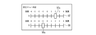
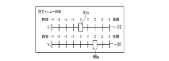
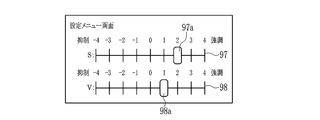
- the emphasis / suppression condition is set by displaying a setting menu screen as shown in FIGS. 8A, 9A, and 10A on the monitor 18.
- FIG. This setting menu screen displays an S slide bar 97 for setting the enhancement / suppression condition of the gland duct structure and a V slide bar 98 for setting the enhancement / suppression condition of the microvessel.
- the structure extraction image signal is input to the fifth conversion unit 94.
- the structure extraction image signal is input to the first conversion unit 90.
- the structure extraction image signal is input to the second conversion unit 91.
- the scales “1” to “4” and “ ⁇ 1” to “-4” on the S slide bar 97 indicate the first to fourth emphasis degrees E1 to E4 and the first to fourth defined on the conversion unit. This corresponds to the fourth suppression degrees R1 to R4. Therefore, when a predetermined scale is set on the slider 97a, the conversion unit 86 sets the enhancement level and the suppression level corresponding to the set scale. For the V slide bar 98, the conditions for emphasizing / suppressing fine blood vessels are set using the slider 98a in the same manner as the S slide bar 97.
- the first converter 90 is set to the slope of the second enhancement degree E2
- the fourth converter 93 is set to the slope of the first suppression degree R1. Then, by inputting the structure extraction image signal to the first conversion unit 90 and the fourth conversion unit 93, the signal values of the pixels of the gland duct structure S and the pixels of the microvessel V as shown in FIG.
- the display control image 100 is output.
- the display control image 100 is used when making a diagnosis by paying attention to the gland duct structure.
- the first conversion unit 90 sets the inclination of the second enhancement degree E2
- the third conversion unit 92 sets the inclination of the first enhancement degree E1. Then, by inputting the structure extraction image signal to the specific conversion unit having both the conversion functions of the first conversion unit 90 and the third conversion unit 92, the signal value of the pixel of the gland duct structure as shown in FIG. 10C Is displayed, and the display control image 102 in which the signal value of the pixel of the microvessel is negative is output.
- the display control image 102 since the enhancement level of the gland duct structure is higher than the enhancement level of the microvessel, the absolute value of the pixel value of the gland duct structure is larger than the absolute value of the pixel value of the microvessel. Yes. Therefore, the display control image 102 is used when the visibility of the gland duct structure is desired to be higher than that of the microvessel while enhancing both the gland duct structure and the microvessel.
- the image composition unit 83 composes a display control image with a base image to create a display control image in which a gland duct structure or a fine blood vessel is emphasized / suppressed.
- the value of each pixel of the enhanced / suppressed image is added to each pixel (Bch) of the B image data in the base image, but for each pixel of the G image data or R image data.
- the value of each pixel of the enhanced / suppressed image may be added.
- the display control image 100 in which the signal values of the pixels of the gland duct structure S and the microvessel V are both positive is synthesized with Bch (each pixel of the B image data) of the base image 105.
- Bch each pixel of the B image data
- the display control image 110 in which the contrast between the gland duct structure S and the surrounding mucosa M is improved while the contrast between the microvessel V and the surrounding mucosa M is reduced is obtained.
- the dotted line indicates the luminance value before synthesis).
- FIG. 11C When the display control image 101 in which the signal value of the pixel of the fine blood vessel V is negative as shown in FIG. 9C is combined with the base image 105, the fine blood vessel V and the surrounding mucosa are shown in FIG. A display control image 111 with improved contrast with M is obtained (as in FIG. 11, the dotted line indicates the luminance value before synthesis).
- the display control image 102 in which the signal value of the pixel of the gland duct structure S as shown in FIG. 10C is positive and the signal value of the pixel of the microvessel V is negative is synthesized with the base image 105
- FIG. 13 As shown in FIG. 13, a display control image 112 in which the contrast between the gland duct structure S and the fine blood vessels V and the surrounding mucous membrane M is improved is obtained (similar to FIG. 11, the dotted line indicates the luminance value before synthesis). ).
- the image display signal generation unit 66 converts the normal light image or special light image input from the normal light image processing unit 62 or the special light image processing unit 64 into a display image signal for display as a displayable image on the monitor 18. To do. Based on the display image signal after the conversion, the monitor 18 displays a normal light image or a special light image.
- screening is performed from a distant view state in the normal observation mode.
- a site possibly site of lesion
- the zoom operation unit 22c is operated to perform enlarged observation to display the site of possible lesion in an enlarged manner.
- the mode switching SW 22b is operated to switch to the special observation mode. Thereby, the special light image is displayed on the monitor 18.
- the surgeon observes the special light image displayed on the monitor 18 and reads the state of the gland duct structure and the microvessel to determine whether or not there is a lesion.
- the console 20 is operated to launch the setting menu screen shown in FIG. 8A and the like.
- the sliders 97a and 98a on the S slide bar 97 and the V slide bar 98 are operated to enhance / suppress the gland duct structure and microvessels on the special light image.
- the slider 97a on the S slide bar 97 is slid in the emphasized direction.
- the slider 98a on the V slide bar 98 is slid in the restraining direction.
- the entire structure extraction image signal is input to the display control image generation unit 82 without distinguishing the up edge and the down edge, and the display control image signal is displayed.
- the display control image may be generated by discriminating the up edge and the down edge and applying gain processing to each.
- a pixel having a positive value in the structure extraction image signal is defined as an up-edge pixel.
- a pixel having a negative value is discriminated as a down-edge pixel.
- the gain processing unit 122 in the display control image generation unit 82 performs gain processing on the up-edge and down-edge pixels according to the degree of enhancement and the degree of suppression to generate a display control image.
- an enhancement gain process is performed on the up-edge pixels to generate a display control image in which the value of the up-edge pixels is positive.
- the up-edge pixel value (positive) increases as the degree of enhancement increases.
- a gain control process is performed on the up-edge pixel to create a display control image in which the value of the up-edge pixel is negative. In this case, the up-edge pixel value (negative) decreases as the degree of suppression increases.
- a gain control for emphasis is performed on the down edge pixel in accordance with the degree of enhancement to generate a display control image in which the value of the down edge pixel is negative.
- the value (negative) of the down edge pixel decreases as the enhancement degree increases.
- a gain processing for suppression corresponding to the degree of suppression is performed on the pixel at the down edge to create a display control image in which the value of the pixel at the down edge is positive. In this case, the pixel value (positive) of the down edge increases as the degree of suppression increases.
- the enhancement level for the down edge is set lower than the enhancement level for the up edge.
- the absolute value of the pixel value (positive) of the up edge is larger than the absolute value of the pixel value (negative) of the down edge.
- both the gland duct structure and the fine blood vessels are extracted from the B image signal by the frequency filtering process.
- the filtering process for gland duct extraction and the filtering process for blood vessel extraction are performed. Separately, the duct structure and microvessels are extracted separately from the B image signal. Considering that the frequency band of the gland duct structure and the frequency band of the microvessel are slightly higher in the frequency of the microvessel, the filtering process for extracting the gland duct and the filtering process for extracting the blood vessel, as in the second embodiment, It is preferable to extract them separately.
- the structure enhancement / suppression unit 130 of the second embodiment is provided with a gland duct extraction filtering unit 131 and a blood vessel extraction filtering unit 132 instead of the frequency filtering unit 81 of the first embodiment.
- the endoscope system of the third embodiment has substantially the same configuration as that of the first embodiment.
- the duct extraction filtering unit 131 performs frequency filtering on the B image signal to extract a band containing a large number of duct structures. Thereby, the duct extraction image signal which extracted the duct structure is produced
- the duct extraction image signal is input to any of the first conversion unit 90, the second conversion unit 91, and the fifth conversion unit 94 of the conversion unit 86.
- the blood vessel extraction filtering unit 132 performs frequency filtering on the B image signal to extract a high-frequency band including many fine blood vessels. Thereby, the blood vessel extraction image signal which extracted the fine blood vessel is produced
- the blood vessel extraction image signal is input to any of the third conversion unit 92, the fourth conversion unit 93, and the sixth conversion unit 95 of the conversion unit 86.
- a suppression processing unit 142 that blurs the base image is provided between the base image generation unit 80 and the image synthesis unit 83.
- a display control image generation unit 144 that creates a display control image is provided.
- the structure enhancement / suppression setting unit 87 controls the suppression processing unit 142 and the display control image generation unit 144 based on the set enhancement / suppression condition.
- the endoscope system of the third embodiment has substantially the same configuration as that of the first embodiment.
- the suppression processing unit 142 performs a process of blurring the base image based on the suppression degree set by the structure enhancement / suppression setting unit 87.
- the degree of blurring increases as the degree of suppression increases.
- low-pass filtering is preferably used as the blurring process.
- the display control image generation unit 144 includes a conversion unit 145 that inputs a structure extraction image signal and outputs a display control image.
- the conversion unit 145 includes a first conversion unit 90, a third conversion unit 92, a fifth conversion unit 94, and a sixth conversion unit 95, and a conversion unit (second conversion) regarding suppression. Section 91 and the fourth conversion section 93) are not provided.
- the present invention is implemented by a simultaneous method in which a plurality of image signals necessary for each observation mode are simultaneously acquired by a color sensor, but instead, it is necessary for each observation mode.
- the present invention can be similarly implemented even in a frame sequential type in which a plurality of image signals are sequentially acquired by a monochrome sensor.
- the light source device 14 of the field sequential endoscope system 200 includes a broadband light source 202, a rotary filter 204, and a blue laser light source 34, a blue-violet laser light source 36, and a light source control unit 40.
- a filter switching unit 205 is provided.
- the phosphor 44 is not provided in the illumination optical system 24a of the endoscope 12.
- the imaging optical system 24b is provided with a monochrome image sensor 206 without a color filter, instead of the color image sensor 48. Other than that, it is the same as the endoscope system 10 of the first embodiment.
- the broadband light source 22 is a xenon lamp, a white LED or the like, and emits white light having a wavelength range from blue to red.
- the rotary filter 204 includes a normal observation mode filter 208 provided inside and a special observation mode filter 209 provided outside (see FIG. 19).
- the filter switching unit 205 moves the rotary filter 204 in the radial direction.
- the filter switching unit 205 inserts the normal observation mode filter 208 of the rotary filter 204 into the white light path.
- the special observation mode filter 209 of the rotation filter 204 is inserted into the optical path of white light.
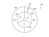
- the normal observation mode filter 208 includes a B filter 208 a that transmits blue light of white light, a G filter 208 b that transmits green light of white light, and white light along the circumferential direction. Among them, an R filter 20c that transmits red light is provided. Therefore, in the normal observation mode, the rotating filter 204 rotates, and blue light, green light, and red light are alternately irradiated into the specimen.
- the special observation mode filter 209 transmits, along the circumferential direction, a Bn filter 209a that transmits blue narrow-band light having a center wavelength of 415 nm in white light and green narrow-band light having a center wavelength of 540 nm among white light.
- a Gn filter 209b is provided. Therefore, in the special observation mode, the rotating filter 204 is rotated so that blue narrow band light and green narrow band light are alternately irradiated into the specimen. Therefore, in the field sequential endoscope system 200, the broadband light source 202 and the Bn filter 209 of the rotary filter 204 constitute a narrow band light source unit of the present invention.
- the inside of the specimen is imaged by the monochrome image sensor 206 every time blue light, green light, and red light are irradiated into the specimen.
- RGB image signals of three colors are obtained.
- a normal light image is generated by the same method as in the first embodiment.
- the special observation mode every time blue narrow band light or green narrow band light is irradiated into the specimen, the inside of the specimen is imaged by the monochrome image sensor 206. Thereby, a Bn image signal and a Gn image signal are obtained. A special light image is generated based on the Bn image signal and the Gn image signal. Unlike the first embodiment, for the generation of the base image, the Bn image signal is assigned to the B image data and the G image data, and the Gn image signal is assigned to the R image data. In addition, a Bn signal is used instead of the B image signal for generating the display control image. Other than that, the special light image is generated by the same method as in the first embodiment.
- the phosphor 44 is provided at the distal end portion 24 of the endoscope 12, but the phosphor 44 may be provided in the light source device 14 instead. In this case, it is preferable to provide a phosphor 44 between the ride guide 41 and the blue laser light source 34.
- the simultaneous endoscope system 10 uses the B image signal, which is a narrowband signal including narrowband wavelength information of the blue laser light and the blue-violet laser light, in the creation of the display control image, and performs the above-described frame sequential.
- a Bn image signal that is a narrowband signal including narrowband wavelength information of blue narrowband light is used to create a display control image.
- a spectrum based on a broadband image such as a white image is used.
- a blue narrowband image signal having a large amount of information on the gland duct structure and microvessels may be generated by calculation, and this blue narrowband image may be used to create a display control image.
- a spectral calculation unit 300 provided between the receiving unit 54 and the color enhancement unit 76 performs a spectral calculation process based on an RGB image signal obtained by light emission and imaging of white light.
- a blue narrow band image signal (for example, a blue narrow band image signal having wavelength information of 415 nm) having a large amount of information regarding the gland duct structure and the fine blood vessels is generated.
- the method described in JP-A-2003-093336 is used as the spectroscopic calculation method.
- a display control image is generated in the same procedure as in the above embodiment.
- white light in addition to the white light obtained by the phosphor 44, broadband light emitted from a broadband light source such as a xenon lamp may be used.
- the present invention is performed during the diagnosis of the endoscope.
- the present invention is not limited to this, and the endoscope recorded in the recording unit of the endoscope system after the endoscope diagnosis.
- the present invention may be carried out based on the mirror image, or may be carried out based on the capsule endoscope image acquired by the capsule endoscope.
Landscapes
- Engineering & Computer Science (AREA)
- Health & Medical Sciences (AREA)
- Physics & Mathematics (AREA)
- Life Sciences & Earth Sciences (AREA)
- Multimedia (AREA)
- Signal Processing (AREA)
- Surgery (AREA)
- Optics & Photonics (AREA)
- Pathology (AREA)
- Medical Informatics (AREA)
- Biophysics (AREA)
- Nuclear Medicine, Radiotherapy & Molecular Imaging (AREA)
- Veterinary Medicine (AREA)
- Radiology & Medical Imaging (AREA)
- Public Health (AREA)
- Biomedical Technology (AREA)
- Heart & Thoracic Surgery (AREA)
- General Health & Medical Sciences (AREA)
- Molecular Biology (AREA)
- Animal Behavior & Ethology (AREA)
- Astronomy & Astrophysics (AREA)
- General Physics & Mathematics (AREA)
- Human Computer Interaction (AREA)
- Endoscopes (AREA)
- Image Processing (AREA)
Abstract
微細血管、微細構造をそれぞれ独立に診断する際に、一方の構造が他方の構造の視認性を妨げることがない内視鏡画像を生成する画像処理装置及び内視鏡システムの作動方法を提供する。 ベース画像(105)には、粘膜よりも明るい腺管構造Sと粘膜よりも暗い微細血管Vを有するB画像信号が含まれる。B画像信号に対して、腺管構造S及び微細血管Vを含む周波数成分を抽出する周波数フィルタリング処理を施して、腺管構造Sの画素の値が正であり、微細血管Vの画素の値が負である構造抽出画像信号を生成する。構造抽出画像信号に基づいて、腺管構造Sの強調と微細血管Vの抑制に用いる表示制御用画像(100)を生成する。ベース画像(105)と表示制御用画像(100)との合成により、腺管構造Sが強調され、微細血管Vが抑制された表示制御画像(110)を得る。
Description
本発明は、腺管構造や微細血管に着目して診断を行う画像処理装置及び内視鏡システムの作動方法に関する。
近年の医療においては、光源装置、電子内視鏡、プロセッサ装置を備える内視鏡システムを用いた診断等が広く行われている。内視鏡システムによる検体内の観察としては、ブラウニッシュエリアや発赤など病変部である可能性が高い病変可能性部位を遠景状態から検出するスクリーニング観察の他、そのような病変可能性部位を検出したときに、ズーミングレンズを用いて、その病変可能性部位を拡大して精査する拡大観察が行われている。この拡大観察では、近年、微細な粘膜構造について着目して診断する「VS classification」が行わるようになってきている。
この「VS classification」では、粘膜表層にある微細血管と粘膜表層の微細構造をそれぞれ独立に診断するため、微細血管と微細構造の両方を強調表示することが求められている。この強調表示に関しては、例えば、特許文献1のように、所定の画像から血管部分を抽出し、その抽出した血管部分だけを強調することが考えられる。この特許文献1のように、血管部分は強調するものの、その血管部分以外の微細構造については消滅させることなく表示を維持することで、微細血管と微細構造の両方を観察しやすくなる。また、微細血管と微細構造はいずれも中周波~高周波成分を有するため、特許文献2のように、ハイパスフィルタリング処理を行うことで、微細血管と微細構造の両方を強調表示することができる。
最近の「VS classification」では、微細構造に着目して診断を行う際に、血管の存在が正確な微細構造の診断に妨げになることが分かってきた。例えば、微細構造が一部消滅しているのにも関わらず、その一部消滅した領域の中に血管が混じっている場合には、その血管に囲まれた部分が、あたかも微細構造のように見えてしまうおそれがある。このような場合には、誤診断の可能性が高くなる。したがって、微細血管、微細構造のうち一方を強調し、他方を抑制すること(微細血管、微細構造の選択的強調・抑制)など互いの視認性を異ならせる表示制御を行うことにより、一方の構造が他方の構造の視認性を妨げることがない内視鏡画像を生成して表示することが求められている。
これに関して、特許文献1には、表層血管と深層血管の選択的強調・抑制については記載があるものの、微細血管、微細構造の選択的強調・抑制に関する説明はない。また、特許文献2には、微細構造と微細血管の両方を強調できるフィルタリング処理が記載されているものの、この特許文献2のフィルタリング処理では微細血管、微細構造の選択的強調・抑制を行うことはできない。
本発明は、微細血管、微細構造をそれぞれ独立に診断する場合であっても、一方の構造が他方の構造の視認性を妨げることがない内視鏡画像を生成することができる画像処理装置及び内視鏡システムの作動方法を提供することを目的とする。
上記目的を達成するために、本発明の画像処理装置は、画像信号生成部と、ベース画像生成部と、構造抽出画像生成部と、表示制御用画像生成部と、画像合成部とを備えている。画像信号生成部は、粘膜表面を撮像して複数色の画像信号を生成する。ベース画像生成部は、複数色の画像信号に基づいてベース画像を生成する。構造抽出画像生成部は、複数色の画像信号のうち短波長の成分を含む短波長画像信号に対して、第1周波数成分を抽出する第1周波数成分抽出処理を施すことにより、信号値が正である第1構造の画素を抽出した第1構造抽出画像信号を生成する。表示制御用画像生成部は、第1構造抽出画像信号に基づいて、第1構造の表示制御に用いる表示制御用画像を生成する。画像合成部は、ベース画像と表示制御用画像を合成して、第1構造の表示を制御した表示制御画像を生成する。
短波長画像信号は青色成分を含むB画像信号であることが好ましい。B画像信号は青色狭帯域画像信号であることが好ましい。青色狭帯域光を発光する狭帯域光源部を備え、青色狭帯域画像信号は、画像信号生成部において、青色狭帯域光で照明された粘膜表面を撮像して得られることが好ましい。複数色の画像信号に基づいて、分光演算する分光演算部を備え、青色狭帯域画像信号は、分光演算によって得られることが好ましい。粘膜表面を拡大する拡大手段を備え、短波長画像信号は、拡大手段を用いる拡大観察時に得られることが好ましい。
構造抽出画像生成部は、第1周波数成分抽出処理を短波長画像信号に施すことにより、信号値が正である第1構造の画素と信号値が負である第2構造の画素を抽出した第1及び第2構造抽出画像信号を生成することが好ましい。表示制御用画像生成部は、第1及び第2構造抽出画像信号に基づいて、第1構造又は第2構造の表示制御に用いる表示制御用画像を生成することが好ましい。画像合成部は、ベース画像と表示制御用画像を合成して、第1構造又は第2構造の表示を制御した表示制御画像を生成することが好ましい。
表示制御用画像生成部は、第1及び第2構造抽出画像信号の入力に対して、第1又は第2構造の画素が表示制御量に応じた値を持つ表示制御用画像を出力する変換部であることが好ましい。変換部は、第1構造の表示を強調するときに、第1構造の画素が強調度に応じた正の値を持つ表示制御用画像を出力する第1変換部を有することが好ましい。変換部は、第1構造の表示を抑制するときに、第1構造の画素が抑制度に応じた負の値を持つ表示制御画像を出力する第2変換部を有することが好ましい。変換部は、第2構造の表示を強調するときに、第2構造の画素が強調度に応じた負の値を持つ表示制御用画像を出力する第3変換部を有することが好ましい。変換部は、第2構造の表示を抑制するときに、第2構造の画素が抑制度に応じた正の値を持つ表示制御用画像を出力する第4変換部を有することが好ましい。変換部は、第1及び第2構造の両方を強調しつつ、第1構造と第2構造の視認性を異ならせるときに、第1構造の画素が正の値が持ち、第2構造の画素が負の値を持つとともに、且つ第1構造の画素の値と第2構造の画素の値の絶対値とが異なる表示制御用画像を出力する特定変換部を有することが好ましい。
第1及び第2構造抽出画像信号の各画素の値を判別する判別部と、第1及び第2構造抽出画像信号のうち判別部で正又は負の値を有すると判別された画素に対して、第1又は第2構造の表示制御量に応じたゲイン処理を施して、表示制御用画像を生成するゲイン処理部とを有することが好ましい。ゲイン処理部は、第1及び第2構造の両方を強調しつつ、第1構造と第2構造の視認性を異ならせるときには、判別部で正の値を有すると判別された画素と負の値を有すると判別された画素に対して、それぞれ強調度が異なる強調用のゲイン処理を施すことが好ましい。
ベース画像に対して抑制処理を施す抑制処理部を備えることが好ましい。この場合は、構造抽出画像生成部は、第1周波数成分抽出処理を短波長画像信号に施すことにより、信号値が正である第1構造の画素と信号値が負である第2構造の画素を抽出した第1及び第2構造抽出画像信号を生成し、表示制御用画像生成部は、第1及び第2構造抽出画像信号に基づいて、第1構造又は第2構造のうち一方の特定構造の表示の強調に用いる表示制御用画像を生成し、画像合成部は、抑制処理が施されたベース画像と表示制御用画像を合成して、第1及び第2構造のうち特定構造の表示を強調し、もう一方の構造の表示を抑制した表示制御画像を生成する。第1構造は腺管構造であり、第2構造は微細血管であることが好ましい。
本発明の内視鏡システムの作動方法は、画像信号生成ステップと、ベース画像生成ステップと、構造抽出画像生成ステップと、表示制御用画像生成ステップと、画像合成ステップとを備えている。画像信号生成ステップでは、画像信号生成部が、粘膜表面を撮像して複数色の画像信号を生成する。ベース画像生成ステップでは、ベース画像生成部が、複数色の画像信号に基づいてベース画像を生成する。構造抽出画像生成ステップでは、構造抽出画像生成部が、複数色の画像信号のうち短波長の成分を含む短波長画像信号に対して、第1周波数成分を抽出する第1周波数成分抽出処理を施すことにより、信号値が正である第1構造の画素を抽出した第1構造抽出画像信号を生成する。表示制御用画像生成ステップでは、表示制御用画像生成部が、第1構造抽出画像信号に基づいて、第1構造の表示制御に用いる表示制御用画像を生成する。画像合成ステップでは、画像合成部が、ベース画像と表示制御用画像を合成して、第1構造の表示を制御した表示制御画像を生成する。
本発明によれば、微細血管、微細構造をそれぞれ独立に診断する場合であっても、微細血管、微細構造のうち一方の構造が他方の構造の視認性を妨げることがない内視鏡画像を生成することができる。
[第1実施形態]
図1に示すように、第1実施形態の内視鏡システム10は、内視鏡12と、光源装置14と、プロセッサ装置16と、モニタ18と、コンソール20とを有する。内視鏡12は光源装置14と光学的に接続されるとともに、プロセッサ装置16と電気的に接続される。内視鏡12は、検体内に挿入される挿入部21と、挿入部の基端部分に設けられた操作部22と、挿入部21の先端側に設けられる湾曲部23及び先端部24を有している。操作部22のアングルノブ22aを操作することにより、湾曲部23は湾曲動作する。この湾曲動作に伴って、先端部24が所望の方向に向けられる。
図1に示すように、第1実施形態の内視鏡システム10は、内視鏡12と、光源装置14と、プロセッサ装置16と、モニタ18と、コンソール20とを有する。内視鏡12は光源装置14と光学的に接続されるとともに、プロセッサ装置16と電気的に接続される。内視鏡12は、検体内に挿入される挿入部21と、挿入部の基端部分に設けられた操作部22と、挿入部21の先端側に設けられる湾曲部23及び先端部24を有している。操作部22のアングルノブ22aを操作することにより、湾曲部23は湾曲動作する。この湾曲動作に伴って、先端部24が所望の方向に向けられる。
また、操作部22には、アングルノブ22aの他、モード切替SW22bと、ズーム操作部22cが設けられている。モード切替SW22bは、通常観察モードと、特殊観察モードの2種類のモード間の切り替え操作に用いられる。通常観察モードは、白色光を用いる観察モードであり、主に、スクリーニング等で使用される。特殊観察モードは青味を帯びた特殊光を用いる観察モードであり、主に、拡大観察等で使用される。ズーム操作部22cは、内視鏡12内のズーミングレンズ47(図2参照)を駆動させて、検体を拡大させるズーム操作に用いられる。
プロセッサ装置16は、モニタ18及びコンソール20と電気的に接続される。モニタ18は、画像情報等を出力表示する。コンソール20は、機能設定等の入力操作を受け付けるUI(ユーザーインターフェース)として機能する。なお、プロセッサ装置16には、画像情報等を記録する外付けの記録部(図示省略)を接続してもよい。
図2に示すように、光源部14は、中心波長445nmの青色レーザ光を発する青色レーザ光源(445LD)34と、中心波長405nmの青紫色レーザ光を発する青紫色レーザ光源(405LD)36とを発光源として備えている。これら各光源34、36の半導体発光素子からの発光は、光源制御部40により個別に制御されており、青色レーザ光源34の出射光と、青紫色レーザ光源36の出射光の光量比は変更自在になっている。光源制御部40は、通常観察モードの場合には、青色レーザ光源34のみ駆動させる。これに対して、特殊観察モードの場合には、光源制御部40は、青色レーザ光源34と青紫色レーザ光36の両方を駆動させるとともに、青紫色レーザ光の発光比率を青色レーザ光の発光比率よりも大きくなるように制御している。なお、青色レーザ光源34及び青紫色レーザ光源36のいずれか又は両方が、本発明の狭帯域光源部を構成する。
なお、青色レーザ光又は青紫色レーザ光の半値幅は±10nm程度にすることが好ましい。また、通常観察モードの場合にも、青紫色レーザ光36を駆動してもよい。ただし、この場合には、青紫色レーザ光36の発光強度を低く抑えることが好ましい。また、青色レーザ光源34及び青紫色レーザ光源36は、ブロードエリア型のInGaN系レーザダイオードが利用でき、また、InGaNAs系レーザダイオードやGaNAs系レーザダイオードを用いることもできる。また、上記光源として、発光ダイオード等の発光体を用いた構成としてもよい。
これら各光源34、36から出射されるレーザ光は、集光レンズ、光ファイバ、合波器などの光学部材(いずれも図示せず)を介して、ライトガイド(LG)41に入射する。ライトガイド41は、内視鏡12及びユニバーサルコード(光源装置14と内視鏡12を接続するためのコード)内に内蔵されている。中心波長445nmの青色レーザ光又は中心波長405nmの青紫色レーザは、ライトガイド41を介して、内視鏡12の先端部24まで伝搬される。なお、ライトガイド41としては、マルチモードファイバを使用することができる。一例として、コア径105μm、クラッド径125μm、外皮となる保護層を含めた径が φ0.3~0.5mmの細径なファイバケーブルを使用することができる。
内視鏡の先端部24は照明光学系24aと撮像光学系24bを有している。照明光学系24aには、ライトガイド41からの中心波長445nmの青色レーザ光又は中心波長405nmの青紫色レーザが入射する蛍光体44と、照明レンズ45が設けられている。蛍光体44に、青色レーザ光が照射されることで、蛍光体44から蛍光が発せられる。また、一部の青色レーザ光は、そのまま蛍光体44を透過する。青紫色レーザ光は、蛍光体44を励起させることなく透過する。蛍光体44を出射した光は、照明レンズ45を介して、検体内に照射される。
ここで、通常観察モードにおいては、青色レーザ光のみが蛍光体44に入射するため、図3Aに示すように、青色レーザ光、及び青色レーザ光により蛍光体44から励起発光する蛍光を合波した白色光が、検体内に照射される。一方、特殊観察モードにおいては、青紫色レーザ光と青色レーザ光の両方が蛍光体44に入射するため、青紫色レーザ光、青色レーザ光、及び青色レーザ光により蛍光体44から励起発光する蛍光を合波した特殊光が、検体内に照射される。この特殊観察モードでは、青紫色レーザ光の発光比率を青色レーザ光の発光比率よりも大きくしているため、特殊光は、青色成分を多く含み且つ波長範囲がほぼ可視光全域に及ぶ光となっている。
なお、蛍光体44は、青色レーザ光の一部を吸収して、緑色~黄色に励起発光する複数種の蛍光体(例えばYAG系蛍光体、或いはBAM(BaMgAl10O17)等の蛍光体)を含んで構成されるものを使用することが好ましい。本構成例のように、半導体発光素子を蛍光体44の励起光源として用いれば、高い発光効率で高強度の白色光が得られ、白色光の強度を容易に調整できる上に、白色光の色温度、色度の変化を小さく抑えることができる。
図2に示すように、内視鏡12の撮像光学系24bは、対物レンズ46、ズーミングレンズ47、イメージセンサ48を有している。検体からの反射光は、対物レンズ46及びズーミングレンズ47を介して、イメージセンサ48に入射する。これにより、イメージセンサ48に検体の反射像が結像される。ズーミングレンズ47は、ズーム操作部22cを操作することで、テレ端とワイド端との間を移動する。ズーミングレンズ47がワイド端側に移動すると検体の反射像が縮小する一方で、テレ端側に移動することで、検体の反射像が拡大する。
イメージセンサ48はカラーの撮像素子であり、検体の反射像を撮像して画像信号を出力する。なお、イメージセンサ48は、CCD(Charge Coupled Device)イメージセンサやCMOS(Complementary Metal-Oxide Semiconductor)イメージセンサ等であることが好ましい。本発明で用いられるイメージセンサは、R(赤)、G(緑)及びB(青)の3色の画像信号を得るために、撮像面にRGBフィルタを備えた、いわゆるRGBカラーイメージセンサであっても良いし、撮像面にC(シアン)、M(マゼンタ)、Y(イエロー)及びG(緑)の色フィルタを備えた、いわゆる補色イメージセンサであっても良い。補色イメージセンサの場合には、CMYGの4色の画像信号から色変換によってRGBの3色の画像信号を得ることができる。この場合には、CMYGの4色の画像信号からRGBの3色の画像信号に色変換する色変換手段を、内視鏡12、光源装置14又はプロセッサ装置16のいずれかに備えている必要がある。
イメージセンサ48から出力される画像信号は、CDS・AGC回路50に送信される。CDS・AGC回路50は、アナログ信号である画像信号に相関二重サンプリング(CDS)や自動利得制御(AGC)を行う。CDS・AGC回路50を経た画像信号は、A/D変換器(A/Dコンバータ)52により、デジタル画像信号に変換される。A/D変換されたデジタル画像信号は、プロセッサ装置16に入力される。
プロセッサ装置16は、受信部54と、画像処理切替部60と、通常光画像処理部62と、特殊光画像処理部64と、画像表示信号生成部66とを備えている。受信部54は内視鏡12からのデジタル画像信号を受信する。この受信部54は、DSP(Digital Signal Processor)56とノイズ除去部58を備えている。DSP56は、デジタル画像信号に対してガンマ補正、色補正処理を行う。ノイズ除去部58は、DSP56でガンマ補正等が施されたデジタル画像信号に対してノイズ除去処理(例えば移動平均法やメディアンフィルタ法等)を施すことによって、デジタル画像信号からノイズを除去する。ノイズが除去されたデジタル画像信号は、画像処理切替部60に送信される。
画像処理切替部60は、モード切替SW22bにより通常観察モードにセットされている場合には、デジタル画像信号を通常光画像処理部62に送信し、特殊観察モードに設定されている場合には、デジタル画像信号を特殊光画像処理部64に送信する。なお、本発明においては、区別のため、通常光画像処理部62及び特殊光画像処理部64による画像処理前のデジタル画像信号を画像信号といい、画像処理後のデジタル画像信号を画像データと呼ぶことにする。
通常光画像処理部62は、色変換部68と、色彩強調部70と、構造強調部72とを有する。色変換部68は、入力されたRGB3チャンネルのデジタル画像信号を、それぞれR画像データ、G画像データ、B画像データに割り付ける。これらRGBの画像データに対しては、更に、3×3のマトリックス処理、階調変換処理、3次元LUT処理などの色変換処理を行い、色変換処理済RGB画像データに変換する。
色彩強調部70は、色変換済RGB画像データに対して、各種色彩強調処理を施す。構造強調部72は、色彩強調処理済RGB画像データに対して、シャープネスや輪郭強調等の構造強調処理を行う。構造強調部72で構造強調処理が施されたRGB画像データは、通常光画像として通常光画像処理部62から画像表示信号生成部66に入力される。
特殊光画像処理部64は、色彩強調部76と、構造強調・抑制部78とを有する。色彩強調部76は、入力されたRGB3チャンネルのデジタル画像信号に対して各種色彩強調処理を施すことにより、色彩強調済のRGBの画像信号を生成する。構造強調・抑制部78は、色彩強調処理済のRGB画像信号に対し、腺管構造又は血管を強調・抑制する構造強調・抑制処理を施すことにより、表示制御画像生成する。構造強調・抑制部78で構造強調・抑制処理が施された表示制御画像は、特殊光画像として特殊光画像処理部64から画像表示信号生成部66に入力される。
図4に示すように、構造強調・抑制部78は、ベース画像生成部80と、周波数フィルタリング処理部81と、表示制御用画像生成部82と、画像合成部83とを備えている。ベース画像生成部80は、色彩強調処理済のRGB画像信号のうち、G画像信号をR画像データに割り付け、B画像信号をG画像データ及びB画像データに割り付ける。これらRGB画像データがベース画像となる。このベース画像は、B画像データにはB画像信号が割り付けられているものの、G画像データにはG画像信号ではなくB画像信号が割り付けられており、R画像データにはR画像信号ではなくG画像信号が割り付けられているため、ベース画像は疑似カラー画像となる。なお、ベース画像生成部では、色変換部68のように、RGB画像信号をそれぞれRGB画像データに割り付けて、疑似カラーでない白色ベースのベース画像を生成してもよい。
周波数フィルタリング処理部81は、色彩強調済のB画像信号に対して、粘膜表層にある腺管構造と微細血管に対応する周波数帯域成分を抽出する周波数フィルタリング処理を施す。ここで、周波数フィルタリング処理で抽出する腺管構造S(Structure)は、白く縁取られて見える辺縁部とする(腺管には辺縁部の他、腺管開口部も含まれている)。これにより、腺管構造と微細血管が抽出された構造抽出画像信号が得られる。B画像信号に対して周波数フィルタリング処理を施すのは、B画像信号は、腺管構造や微細血管に対して構造強調効果を施すことができる青紫色レーザ光及び青色レーザ光など青色成分に対応する信号であるためである。
なお、図5(A)に示すように、腺管構造S(Structure)は、青紫色レーザ光及び青色レーザ光など青色成分の光によって乱反射するため、B画像信号84上では粘膜よりも明るく光っている。また、青紫色レーザ光及び青色レーザ光は、キセノン光などの広帯域光を波長分離して得られる青色狭帯域光と異なり、直進性の高い光であるため、腺管構造のpit部分の底面まで深達する。この効果によって、腺管構造Sは更に明るく光るようになる。これに対して、微細血管V(Vascular)は、特殊光のうち青紫色レーザ光及び青色レーザ光などヘモグロビンの吸光係数が高い青色成分の光を良く吸収するため、B画像信号84上では粘膜よりも暗くなっている。したがって、周波数フィルタリング処理後の構造抽出画像信号85では、(B)に示すように、腺管構造Sの画素は信号値が「正」となるアップエッジとなっており、微細血管Vの画素は信号値が「負」となるダウンエッジとなっている。また、構造抽出画像信号85における粘膜M(Mucous membrane)は、輝度値の変化がほとんど無いため、信号値はほぼ「0」となっている。なお、図5において、B画像信号84はライン84a上の各画素の輝度値を表しており、構造抽出画像信号85はライン84a上の各画素の信号値を表している(図11~図13も同様)。また、ここで、信号値は「0」、正の値、負の値を含む値であり、輝度値は「0」、正の値を含む値である。
表示制御用画像生成部82は、構造抽出画像信号から、腺管構造又は微細血管の強調・抑制・表示維持に用いられるための表示制御用画像を生成する。表示制御用画像生成部82は、構造抽出画像信号を入力して表示制御用画像を出力する変換部86と、強調・抑制条件を設定するとともに、設定した強調・抑制条件に従って変換部を制御する構造強調・抑制設定部87とを備えている(図4参照)。
図6に示すように、変換部86は、第1変換部90と、第2変換部91と、第3変換部92と、第4変換部93と、第5変換部94と、第6変換部95とからなり、構造抽出画像信号の入力に対して、腺管構造又は微細血管の強調度、抑制度など表示制御量に応じた値を持つ表示制御用画像を出力する。第1変換部90は、腺管構造を強調するときに用いられ、構造抽出画像信号の入力に対して、図7に示す入出力関係90aに従った値を出力する。入出力関係90aは正の傾きで定義されているため、正の値の入力に対して、正の値を出力する。この出力した正の値を、ベース画像上の腺管構造に加算することで、粘膜よりも明るい腺管構造が更に明るくなり、粘膜と腺管構造とのコントラストが向上する。これにより、腺管強調効果が得られる。なお、第1変換部90では、4つの第1~第4強調度E1~E4に対応する入出力関係が定義されており、それらの傾きは、強調度が高くなる程、大きくなっている。
第2変換部91は、腺管構造を抑制するときに用いられ、構造抽出画像信号の入力に対して、図7に示す入出力関係91aに従った値を出力する。入出力関係91aは負の傾きで定義されているため、正の値の入力に対して、負の値を出力する。この出力した負の値を、ベース画像上の腺管構造に加算することで、腺管構造の明るさが粘膜に近づいて、粘膜と腺管構造とのコントラストが低下する。これにより、腺管抑制効果が得られる。なお、第2変換部91では、4つの第1~第4抑制度R1~R4に対応する入出力関係が定義されており、それらの傾きは、抑制度が高くなる程、大きくなっている。
第3変換部92は、微細血管を強調するときに用いられ、構造抽出画像信号の入力に対して、図7に示す入出力関係92aに従った値を出力する。入出力関係92aは正の傾きで定義されているため、負の値の入力に対して、負の値を出力する。この出力した負の値を、ベース画像上の微細血管に加算することで、粘膜よりも暗い微細血管が更に暗くなって、粘膜と微細血管とのコントラストが向上する。これにより、微細血管強調効果が得られる。なお、第3変換部92では、4つの第1~第4強調度E1~E4に対応する入出力関係が定義されており、それらの傾きは、強調度が高くなる程、大きくなっている。
第4変換部93は、微細血管を抑制するときに用いられ、図7に示す入出力関係93aに従った値を出力する。入出力関係93aは負の傾きで定義されているため、負の値の入力に対して、正の値を出力する。この出力した正の値を、ベース画像上の微細血管に加算することで、微細血管の明るさが粘膜に近づいて、粘膜と微細血管とのコントラストが低下する。これにより、微細血管抑制効果が得られる。なお、第4変換部93では、4つの第1~第4抑制度R1~R4に対応する入出力関係が定義されており、それらの傾きは、抑制度が高くなる程、大きくなっている。
第5変換部94は、腺管構造の明るさを維持するときに用いられ、構造抽出画像信号のうち正の値の入力に対して、図7に示す入出力関係94aに従って、「0」の値を出力する。この「0」の値をベース画像上の腺管構造に加算することで、腺管構造の明るさは維持される。第6変換部95は、微細血管の明るさを維持するときに用いられ、構造抽出画像信号のうち負の値の入力に対して、図7に示す入出力関係95aに従って、「0」の値を出力する。この「0」の値をベース画像上の微細血管に加算することで、微細血管の明るさは維持される。
構造強調・抑制設定部87は、コンソール20によって入力される強調・抑制条件に基づいて、変換部86を制御する。強調・抑制条件の設定は、図8A、図9A、図10Aに示すような設定メニュー画面をモニタ18に表示して行われる。この設定メニュー画面は、腺管構造の強調・抑制条件を設定するためのS用スライドバー97と、微細血管の強調・抑制条件を設定するためのV用スライドバー98とが表示される。
S用スライドバー97上でスライダ97aを中央の「0」にセットしたときには、腺管構造の明るさを維持する条件に設定される。この場合には、構造抽出画像信号は第5変換部94に入力される。また、S用スライドバー97上でスライダ97aを右側の強調側にスライドさせたときには、腺管構造を強調する条件に設定される。この場合には、構造抽出画像信号は第1変換部90に入力される。また、スライダ97aを左側の抑制側にスライドさせたときには、腺管構造を抑制する条件に設定される。この場合には、構造抽出画像信号は第2変換部91に入力される。
また、S用スライドバー97上の目盛り「1」~「4」及び「-1」~「-4」は、変換部上で定義された第1~第4強調度E1~E4及び第1~第4抑制度R1~R4に対応している。したがって、スライダ97aを所定の目盛りをセットすると、変換部86では、そのセットされた目盛りに対応する強調度・抑制度に設定される。なお、V用スライドバー98についても、S用スライドバー97と同様の方法で、スライダ98aを用いて微細血管の強調・抑制の条件設定を行う。
例えば、図8Aに示すように、S用スライドバー97上でスライダ97aを「+2」をセットし、V用スライドバー98上でスライダ98aを「-1」にセットした場合には、図8Bに示すように、第1変換部90では、第2強調度E2の傾きにセットされるとともに、第4変換部93では、第1抑制度R1の傾きにセットされる。そして、構造抽出画像信号を第1変換部90及び第4変換部93に入力することにより、図8Cに示すような、腺管構造Sの画素と微細血管Vの画素の信号値が共に正となる表示制御用画像100が出力される。この表示制御用画像100は、腺管構造に着目して診断を行う場合に用いられる。
また、図9Aに示すように、S用スライドバー97上でスライダ97aを「0」をセットし、V用スライドバー98上でスライダ98aを「+2」にセットした場合には、図9Bに示すように、第3変換部92では、第2強調度E2の傾きにセットされる。そして、構造抽出画像信号を第5変換部94及び第3変換部92に入力することにより、図9Cに示すような、腺管構造Sの画素の信号値が「0」で、微細血管Vの画素の信号値が負となる表示制御用画像101が出力される。この表示制御用画像101は、微細血管に着目して診断を行う場合に用いられる。
また、図10Aに示すように、S用スライドバー97上でスライダ97aを「+2」をセットし、V用スライドバー98上でスライダ98aを「+1」にセットした場合には、図10Bに示すように、第1変換部90では、第2強調度E2の傾きにセットされるとともに、第3変換部92では、第1強調度E1の傾きにセットされる。そして、第1変換部90及び第3変換部92の両方の変換機能を有する特定変換部に、構造抽出画像信号を入力することにより、図10Cに示すような、腺管構造の画素の信号値が正であり、微細血管の画素の信号値が負である表示制御用画像102が出力される。
この表示制御用画像102では、腺管構造の強調度が微細血管の強調度よりも高いため、腺管構造の画素の値の絶対値が微細血管の画素の値の絶対値よりも大きくなっている。したがって、表示制御用画像102は、腺管構造と微細血管の両方を強調しつつ、腺管構造の視認性を微細血管よりも高めたい場合に用いられる。
画像合成部83は、表示制御用画像をベース画像に合成することにより、腺管構造又は微細血管を強調・抑制した表示制御画像を作成する。この画像合成部83では、ベース画像のうちB画像データの各画素(Bch)に対して、強調・抑制画像の各画素の値を加算するが、G画像データ又はR画像データの各画素に対しても強調・抑制画像の各画素の値を加算してもよい。
例えば、図8Cのような、腺管構造Sの画素と微細血管Vの画素の信号値が共に正となる表示制御用画像100をベース画像105のBch(B画像データの各画素)に合成した場合には、図11に示すように、腺管構造Sと周囲の粘膜Mとのコントラストが向上する一方で、微細血管Vと周囲の粘膜Mとのコントラストが低下した表示制御画像110が得られる(点線は合成前の輝度値を示している)。
また、図9Cのような、微細血管Vの画素の信号値が負となる表示制御用画像101をベース画像105に合成した場合には、図12に示すように、微細血管Vと周囲の粘膜Mとのコントラストが向上した表示制御画像111が得られる(図11と同様、点線は合成前の輝度値を示している)。また、図10Cのような、腺管構造Sの画素の信号値が正であり、微細血管Vの画素の信号値が負である表示制御用画像102をベース画像105に合成した場合には、図13に示すように、腺管構造S及び微細血管Vと周囲の粘膜Mとのコントラストが向上した表示制御画像112が得られる(図11と同様、点線は合成前の輝度値を示している)。
画像表示信号生成部66は、通常光画像処理部62又は特殊光画像処理部64から入力された通常光画像又は特殊光画像を、モニタ18で表示可能画像として表示するための表示画像信号に変換する。この変換後の表示画像信号に基づいて、モニタ18は、通常光画像又は特殊光画像を表示する。
次に、本実施形態における一連の流れを図14のフローチャートに沿って説明する。まず、通常観察モードにおいて、遠景状態からスクリーニングを行う。このスクリーニング時に、ブラウニッシュエリアや発赤など病変の可能性がある部位(病変可能性部位)を検出したときには、ズーム操作部22cを操作して、その病変可能性部位を拡大表示する拡大観察を行う。これに合わせて、モード切替SW22bを操作して、特殊観察モードに切り替える。これにより、特殊光画像がモニタ18に表示される。
術者は、モニタ18に表示された特殊光画像を観察して、腺管構造及び微細血管の状態を読み取って、病変部が否かを判断する。特殊光画像から腺管構造及び微細血管の状態を正確に読み取ることができる場合には、その特殊光画像に基づいて、病変可能性部位が病変もしくは非病変か否かの判断を行う。一方、腺管構造及び微細血管の状態を正確に読み取ることができない場合には、コンソール20を操作して、図8A等に示す設定メニュー画面を立ち上げる。この設定メニュー画面上で、S用スライドバー97及びV用スライドバー98上にあるスライダ97a,98aを操作して、特殊光画像上での腺管構造及び微細血管の強調・抑制を行う。
例えば、腺管構造に着目して診断を行う際に、微細血管の表示が妨げになっている場合には、図8Aに示すように、S用スライドバー97上のスライダ97aを強調方向にスライドさせる一方、V用スライドバー98上のスライダ98aを抑制方向にスライドさせる。これにより、腺管構造の表示を強調する一方で、微細血管の表示が抑制された特殊光画像がモニタ18に表示される。この腺管構造及び微細血管の強調・抑制は、腺管構造及び微細血管の状態を正確に読み取ることができるまで継続して行われる。
なお、第1実施形態では、周波数フィルタリング画像の構造抽出画像信号において、アップエッジとダウンエッジを判別せずに、構造抽出画像信号全体を表示制御用画像生成部82に入力して、表示制御用画像を生成したが、アップエッジとダウンエッジを判別し、それぞれにゲイン処理を施すことによって表示制御用画像を生成してもよい。例えば、図15に示すように、周波数フィルタリング部81と表示制御用画像生成部82との間に設けた判別部120で、構造抽出画像信号のうち正の値を持つ画素をアップエッジの画素と判別し、負の値を持つ画素をダウンエッジの画素と判別する。そして、表示制御用画像生成部82内のゲイン処理部122で、アップエッジ及びダウンエッジの画素に対して、強調度・抑制度に応じたゲイン処理を施して、表示制御用画像を生成する。
この場合、腺管構造を強調するときには、アップエッジの画素に対して、強調用のゲイン処理を施して、アップエッジの画素の値が正となる表示制御用画像を生成する。この場合におけるアップエッジの画素の値(正)は、強調度が大きくなる程、大きくなる。また、腺管構造を抑制するときには、アップエッジの画素に対して、抑制用のゲイン処理を施して、アップエッジの画素の値が負となる表示制御用画像を作成する。この場合におけるアップエッジの画素の値(負)は、抑制度が大きくなる程、小さくなる。
また、微細血管を強調するときには、ダウンエッジの画素に対して、強調度に応じた強調用のゲイン処理を施して、ダウンエッジの画素の値が負となる表示制御用画像を生成する。この場合におけるダウンエッジの画素の値(負)は、強調度が大きくなる程、小さくなる。また、微細血管を抑制するときには、ダウンエッジの画素に対して、抑制度に応じた抑制用のゲイン処理を施して、ダウンエッジの画素の値が正となる表示制御用画像を作成する。この場合におけるダウンエッジの画素の値(正)は、抑制度が大きくなる程、大きくなる。
また、腺管構造と微細血管の両方を強調しつつ、微細血管の視認性を腺管構造の視認性よりも低くする場合には、アップエッジ及びダウンエッジの画素に対して強調用のゲイン処理を行うときに、ダウンエッジに対する強調度を、アップエッジに対する強調度よりも低くする。この場合には、表示制御用画像上では、アップエッジの画素の値(正)の絶対値は、ダウンエッジの画素の値(負)の絶対値よりも大きくなる。
[第2実施形態]
第1実施形態では、周波数フィルタリング処理により、B画像信号から腺管構造及び微細血管の両方を抽出したが、第2実施形態では、腺管抽出用のフィルタリング処理と血管抽出用のフィルタリング処理とを分けて、B画像信号から腺管構造と微細血管を別々に抽出する。腺管構造の周波数帯域と微細血管の周波数帯域は若干微細血管のほうが高周波寄りであることを考慮すると、第2実施形態のように、腺管抽出用のフィルタリング処理と血管抽出用のフィルタリング処理とに分けて、抽出することが好ましい。
第1実施形態では、周波数フィルタリング処理により、B画像信号から腺管構造及び微細血管の両方を抽出したが、第2実施形態では、腺管抽出用のフィルタリング処理と血管抽出用のフィルタリング処理とを分けて、B画像信号から腺管構造と微細血管を別々に抽出する。腺管構造の周波数帯域と微細血管の周波数帯域は若干微細血管のほうが高周波寄りであることを考慮すると、第2実施形態のように、腺管抽出用のフィルタリング処理と血管抽出用のフィルタリング処理とに分けて、抽出することが好ましい。
第2実施形態の構造強調・抑制部130は、第1実施形態の周波数フィルタリング部81に代えて、腺管抽出用フィルタリング部131と血管抽出用フィルタリング部132が設けられている。なお、それ以外については、第3実施形態の内視鏡システムは、第1実施形態とほぼ同様の構成を有している。
腺管抽出用フィルタリング部131では、B画像信号に対して、腺管構造が多く含まれる帯域を抽出する周波数フィルタリングを行う。これにより、腺管構造を抽出した腺管抽出画像信号が生成される。この腺管抽出画像信号は、変換部86の第1変換部90、第2変換部91、第5変換部94のいずれかに入力される。一方、血管抽出用フィルタリング部132では、B画像信号に対して、微細血管が多く含まれる高周波の帯域を抽出する周波数フィルタリングを行う。これにより、微細血管を抽出した血管抽出画像信号が生成される。この血管抽出画像信号は、変換部86の第3変換部92、第4変換部93、第6変換部95のいずれかに入力される。
[第3実施形態]
第1実施形態では、表示制御用画像をベース画像に合成することによって、腺管構造、微細血管の強調・抑制を行ったが、第3実施形態では、腺管構造、微細血管の強調については、表示制御用画像をベース画像に合成して行う一方で、腺管構造、微細構造の抑制については、ベース画像をぼかす処理で行う。
第1実施形態では、表示制御用画像をベース画像に合成することによって、腺管構造、微細血管の強調・抑制を行ったが、第3実施形態では、腺管構造、微細血管の強調については、表示制御用画像をベース画像に合成して行う一方で、腺管構造、微細構造の抑制については、ベース画像をぼかす処理で行う。
第3実施形態の構造強調・抑制部140では、ベース画像生成部80と画像合成部83との間に、ベース画像をぼかす抑制処理部142が設けられている。また、第1実施形態の表示制御用画像生成部82の代わりに、表示制御用画像を作成する表示制御用画像生成部144が設けられている。また、構造強調・抑制設定部87は、設定した強調・抑制条件に基づいて、抑制処理部142及び表示制御用画像生成部144を制御する。なお、それ以外については、第3実施形態の内視鏡システムは、第1実施形態とほぼ同様の構成を有している。
抑制処理部142は、構造強調・抑制設定部87で設定された抑制度に基づいて、ベース画像をぼかす処理を行う。ぼかしの程度は、抑制度が高くなる程、大きくする。なお、ぼかし処理としては、例えばローパスフィルタリングなどを用いることが好ましい。表示制御用画像生成部144は、構造抽出画像信号を入力して表示制御用画像を出力する変換部145を備えている。変換部145は、変換部86と異なり、第1変換部90、第3変換部92と、第5変換部94と、第6変換部95が設けられており、抑制に関する変換部(第2変換部91、第4変換部93)は設けられていない。
上記第1~第3実施形態では、各観察モードに必要な複数の画像信号をカラーのセンサで同時に取得する同時方式で本発明の実施を行ったが、これに代えて、各観察モードに必要な複数の画像信号をモノクロのセンサで順次取得する面順次式であっても同様に本発明の実施が可能である。
図18に示すように、面順次式の内視鏡システム200の光源装置14には、青色レーザ光源34、青紫色レーザ光源36、光源制御部40の代わりに、広帯域光源202、回転フィルタ204、フィルタ切替部205が設けられている。また、内視鏡12の照明光学系24aには、蛍光体44が設けられていない。また、撮像光学系24bには、カラーのイメージセンサ48の代わりに、カラーフィルタが設けられていないモノクロのイメージセンサ206が設けられている。それ以外については、第1実施形態の内視鏡システム10と同様である。
広帯域光源22はキセノンランプ、白色LEDなどであり、波長域が青色から赤色に及ぶ白色光を発する。回転フィルタ204は、内側に設けられた通常観察モード用フィルタ208と、外側に設けられた特殊観察モード用フィルタ209とを備えている(図19参照)。フィルタ切替部205は、回転フィルタ204を径方向に移動させるものであり、モード切替SW22bにより通常観察モードにセットされたときに、回転フィルタ204の通常観察モード用フィルタ208を白色光の光路に挿入し、特殊観察モードにセットされたときに、回転フィルタ204の特殊観察モード用フィルタ209を白色光の光路に挿入する。
図19に示すように、通常観察モード用フィルタ208には、周方向に沿って、白色光のうち青色光を透過させるBフィルタ208a、白色光のうち緑色光を透過させるGフィルタ208b、白色光のうち赤色光を透過させるRフィルタ20cが設けられている。したがって、通常観察モード時には、回転フィルタ204が回転することで、青色光、緑色光、赤色光が交互に検体内に照射される。
特殊観察モード用フィルタ209には、周方向に沿って、白色光のうち中心波長415nmの青色狭帯域光を透過させるBnフィルタ209aと、白色光のうち中心波長540nmの緑色狭帯域光を透過させるGnフィルタ209bが設けられている。したがって、特殊観察モード時には、回転フィルタ204が回転することで、青色狭帯域光、緑色狭帯域光が交互に検体内に照射される。そのため、面順次式の内視鏡システム200では、広帯域光源202及び回転フィルタ204のBnフィルタ209が、本発明の狭帯域光源部を構成する。
面順次方式の内視鏡システム200では、通常観察モード時には、青色光、緑色光、赤色光が検体内に照射される毎にモノクロのイメージセンサ206で検体内を撮像する。これにより、RGBの3色の画像信号が得られる。そして、それらRGBの画像信号に基づいて、上記第1実施形態と同様の方法で、通常光画像が生成される。
一方、特殊観察モード時には、青色狭帯域光、緑色狭帯域光が検体内に照射される毎にモノクロのイメージセンサ206で検体内を撮像する。これにより、Bn画像信号と、Gn画像信号が得られる。これらBn画像信号と、Gn画像信号に基づいて、特殊光画像の生成が行われる。上記第1実施形態と異なり、ベース画像の生成については、Bn画像信号がB画像データ及びG画像データに割り付けられ、Gn画像信号がR画像データに割り付けられる。また、表示制御用画像の生成には、B画像信号の代わりに、Bn信号が用いられる。それ以外については、第1実施形態と同様の方法で特殊光画像の生成が行われる。
なお、図2に示す第1実施形態では、蛍光体44を内視鏡12の先端部24に設けたが、これに代えて、蛍光体44を光源装置14内に設けてもよい。この場合には、ライドガイド41と青色レーザ光源34との間に、蛍光体44を設けることが好ましい。
なお、上記同時式の内視鏡システム10では、表示制御画像の作成に、青色レーザ光及び青紫色レーザ光の狭帯域波長情報が含まれる狭帯域信号であるB画像信号を用い、上記面順次式の内視鏡システム200では、表示制御画像の作成に、青色狭帯域光の狭帯域波長情報が含まれる狭帯域信号であるBn画像信号を用いたが、白色画像などの広帯域画像に基づく分光演算により、腺管構造及び微細血管に関する情報を多く持つ青色狭帯域画像信号を生成し、この青色狭帯域画像を表示制御画像の作成に用いてもよい。
この場合には、同時式の内視鏡システム10の特殊観察モード時において、特殊光の代わりに、広帯域光である白色光を照明する。そして、図20に示すように、受信部54と色彩強調部76との間に設けた分光演算部300において、白色光の発光・撮像により得られるRGB画像信号に基づく分光演算処理を行う。これにより、腺管構造及び微細血管に関する情報を多く持つ青色狭帯域画像信号(例えば、415nmの波長情報を持つ青色狭帯域画像信号)が生成される。分光演算の方法は、特開2003-093336号公報に記載の方法を用いる。この分光演算部300で生成された青色狭帯域画像信号と、GR画像信号に基づいて、上記実施形態と同様の手順で、表示制御画像を生成する。なお、白色光としては、蛍光体44により得られる白色光の他、キセノンランプなどの広帯域光源から発せられる広帯域光を用いてもよい。
なお、上記実施形態では、本発明の実施を内視鏡の診断中に行っているが、これに限らず、内視鏡診断後に、内視鏡システムの記録部に記録しておいた内視鏡画像に基づいて、本発明の実施を行ってもよく、また、カプセル内視鏡で取得したカプセル内視鏡画像に基づいて、本発明の実施を行ってもよい。
10,200 内視鏡システム
47 ズーミングレンズ(拡大手段)
48,206 センサ(画像信号生成部)
78,130,140 構造強調・抑制部
80 ベース画像生成部
81 周波数フィルタリング部(構造抽出画像生成部)
82,144 表示制御用画像生成部
83 画像合成部
86,145 変換部
90 第1変換部
91 第2変換部
92 第3変換部
93 第4変換部
120 判別部
122 ゲイン処理部
131 腺管抽出用フィルタリング部
132 血管抽出用フィルタリング部
142 抑制処理部
300 分光演算部
47 ズーミングレンズ(拡大手段)
48,206 センサ(画像信号生成部)
78,130,140 構造強調・抑制部
80 ベース画像生成部
81 周波数フィルタリング部(構造抽出画像生成部)
82,144 表示制御用画像生成部
83 画像合成部
86,145 変換部
90 第1変換部
91 第2変換部
92 第3変換部
93 第4変換部
120 判別部
122 ゲイン処理部
131 腺管抽出用フィルタリング部
132 血管抽出用フィルタリング部
142 抑制処理部
300 分光演算部
Claims (19)
- 粘膜表面を撮像して複数色の画像信号を生成する画像信号生成部と、
前記複数色の画像信号に基づいてベース画像を生成するベース画像生成部と、
前記複数色の画像信号のうち短波長の成分を含む短波長画像信号に対して、第1周波数成分を抽出する第1周波数成分抽出処理を施すことにより、信号値が正である第1構造の画素を抽出した第1構造抽出画像信号を生成する構造抽出画像生成部と、
前記第1構造抽出画像信号に基づいて、前記第1構造の表示制御に用いる表示制御用画像を生成する表示制御用画像生成部と、
前記ベース画像と前記表示制御用画像を合成して、前記第1構造の表示を制御した表示制御画像を生成する画像合成部と、
を備えることを特徴とする画像処理装置。 - 前記短波長画像信号は青色成分に対応するB画像信号であることを特徴とする請求項1記載の画像処理装置。
- 前記B画像信号は青色狭帯域画像信号であることを特徴とする請求項2記載の画像処理装置。
- 青色狭帯域光を発光する狭帯域光源部を備え、
前記青色狭帯域画像信号は、前記画像信号生成部において、前記青色狭帯域光で照明された前記粘膜表面を撮像して得られることを特徴とする請求項3記載の画像処理装置。 - 前記複数色の画像信号に基づいて、分光演算する分光演算部を備え、
前記青色狭帯域画像信号は、前記分光演算によって得られることを特徴とする請求項3記載の画像処理装置。 - 前記粘膜表面を拡大する拡大手段を備え、
前記短波長画像信号は、前記拡大手段を用いる拡大観察時に得られることを特徴とする請求項1記載の画像処理装置。 - 前記構造抽出画像生成部は、前記第1周波数成分抽出処理を前記短波長画像信号に施すことにより、信号値が正である第1構造の画素と信号値が負である第2構造の画素を抽出した第1及び第2構造抽出画像信号を生成し、
前記表示制御用画像生成部は、前記第1及び第2構造抽出画像信号に基づいて、前記第1構造又は第2構造の表示制御に用いる表示制御用画像を生成し、
前記画像合成部は、前記ベース画像と前記表示制御用画像を合成して、前記第1構造又は第2構造の表示を制御した表示制御画像を生成する
ことを特徴とする請求項1記載の画像処理装置。 - 前記表示制御用画像生成部は、前記第1及び第2構造抽出画像信号の入力に対して、前記第1又は第2構造の画素が表示制御量に応じた値を持つ表示制御用画像を出力する変換部であることを特徴とする請求項7記載の画像処理装置。
- 前記変換部は、前記第1構造の表示を強調するときに、前記第1構造の画素が強調度に応じた正の値を持つ表示制御用画像を出力する第1変換部を有することを特徴とする請求項8記載の画像処理装置。
- 前記変換部は、前記第1構造の表示を抑制するときに、前記第1構造の画素が抑制度に応じた負の値を持つ表示制御用画像を出力する第2変換部を有することを特徴とする請求項8または9記載の画像処理装置。
- 前記変換部は、前記第2構造の表示を強調するときに、前記第2構造の画素が強調度に応じた負の値を持つ表示制御用画像を出力する第3変換部を有することを特徴とする請求項8ないし10いずれか1項記載の画像処理装置。
- 前記変換部は、前記第2構造の表示を抑制するときに、前記第2構造の画素が抑制度に応じた正の値を持つ表示制御用画像を出力する第4変換部を有することを特徴とする請求項8ないし11いずれか1項記載の画像処理装置。
- 前記変換部は、前記第1及び第2構造の両方を強調しつつ、前記第1構造と前記第2構造の視認性を異ならせるときに、前記第1構造の画素が正の値が持ち、前記第2構造の画素が負の値を持つとともに、記第1構造の画素の値と前記第2構造の画素の値の絶対値とが異なる表示制御用画像を出力する特定変換部を有することを特徴とする請求項8記載の画像処理装置。
- 前記第1及び第2構造抽出画像信号の各画素の値を判別する判別部と、
前記第1及び第2構造抽出画像信号のうち前記判別部で正又は負の値を有すると判別された画素に対して、前記第1又は第2構造の表示制御量に応じたゲイン処理を施して、表示制御用画像を生成するゲイン処理部とを有することを特徴とする請求項7記載の画像処理装置。 - 前記ゲイン処理部は、前記第1及び第2構造の両方を強調しつつ、前記第1構造と前記第2構造の視認性を異ならせるときには、前記判別部で正の値を有すると判別された画素と負の値を有すると判別された画素に対して、それぞれ強調度が異なる強調用のゲイン処理を施すことを特徴とする請求項14記載の画像処理装置。
- 前記ベース画像に対して抑制処理を施す抑制処理部を備え、
前記構造抽出画像生成部は、前記第1周波数成分抽出処理を前記短波長画像信号に施すことにより、信号値が正である第1構造の画素と信号値が負である第2構造の画素を抽出した第1及び第2構造抽出画像信号を生成し、
前記表示制御用画像生成部は、前記第1及び第2構造抽出画像信号に基づいて、前記第1構造又は第2構造のうち一方の特定構造の表示の強調に用いる表示制御用画像を生成し、
前記画像合成部は、前記抑制処理が施されたベース画像と前記表示制御用画像を合成して、前記第1及び第2構造のうち前記特定構造の表示を強調し、もう一方の構造の表示を抑制した表示制御画像を生成する、
ことを特徴とする請求項1ないし6いずれか1項記載の画像処理装置。 - 前記第1構造は腺管構造であることを特徴とする請求項1記載の画像処理装置。
- 前記第1構造は腺管構造であり、前記第2構造は微細血管であることを特徴とする請求項7記載の画像処理装置。
- 画像信号生成部が、粘膜表面を撮像して複数色の画像信号を生成する画像信号生成ステップと、
ベース画像生成部が、前記複数色の画像信号に基づいてベース画像を生成するベース画像生成ステップと、
構造抽出画像生成部が、前記複数色の画像信号のうち短波長の成分を含む短波長画像信号に対して、第1周波数成分を抽出する第1周波数成分抽出処理を施すことにより、信号値が正である第1構造の画素を抽出した第1構造抽出画像信号を生成する構造抽出画像生成ステップと、
表示制御用画像生成部が、前記第1構造抽出画像信号に基づいて、前記第1構造の表示制御に用いる表示制御用画像を生成する表示制御用画像生成ステップと、
画像合成部が、前記ベース画像と前記表示制御用画像を合成して、前記第1構造の表示を制御した表示制御画像を生成する画像合成ステップと、
を有することを特徴とする内視鏡システムの作動方法。
Priority Applications (3)
| Application Number | Priority Date | Filing Date | Title |
|---|---|---|---|
| JP2015502818A JP6017669B2 (ja) | 2013-02-27 | 2014-01-31 | 画像処理装置及び内視鏡システムの作動方法 |
| CN201480010392.8A CN105007801B (zh) | 2013-02-27 | 2014-01-31 | 图像处理装置以及内窥镜系统的工作方法 |
| US14/823,053 US10003774B2 (en) | 2013-02-27 | 2015-08-11 | Image processing device and method for operating endoscope system |
Applications Claiming Priority (2)
| Application Number | Priority Date | Filing Date | Title |
|---|---|---|---|
| JP2013-037782 | 2013-02-27 | ||
| JP2013037782 | 2013-02-27 |
Related Child Applications (1)
| Application Number | Title | Priority Date | Filing Date |
|---|---|---|---|
| US14/823,053 Continuation US10003774B2 (en) | 2013-02-27 | 2015-08-11 | Image processing device and method for operating endoscope system |
Publications (1)
| Publication Number | Publication Date |
|---|---|
| WO2014132741A1 true WO2014132741A1 (ja) | 2014-09-04 |
Family
ID=51428015
Family Applications (1)
| Application Number | Title | Priority Date | Filing Date |
|---|---|---|---|
| PCT/JP2014/052247 Ceased WO2014132741A1 (ja) | 2013-02-27 | 2014-01-31 | 画像処理装置及び内視鏡システムの作動方法 |
Country Status (4)
| Country | Link |
|---|---|
| US (1) | US10003774B2 (ja) |
| JP (1) | JP6017669B2 (ja) |
| CN (1) | CN105007801B (ja) |
| WO (1) | WO2014132741A1 (ja) |
Cited By (3)
| Publication number | Priority date | Publication date | Assignee | Title |
|---|---|---|---|---|
| JP2014212925A (ja) * | 2013-04-25 | 2014-11-17 | 富士フイルム株式会社 | 画像処理装置及び内視鏡システムの作動方法 |
| JP2016067706A (ja) * | 2014-09-30 | 2016-05-09 | 富士フイルム株式会社 | プロセッサ装置、内視鏡システム、プロセッサ装置の作動方法、及びプログラム |
| WO2024157429A1 (ja) * | 2023-01-26 | 2024-08-02 | オリンパスメディカルシステムズ株式会社 | 画像処理装置、医療用システム、画像処理装置の作動方法およびプログラム |
Families Citing this family (4)
| Publication number | Priority date | Publication date | Assignee | Title |
|---|---|---|---|---|
| CN105942960B (zh) * | 2016-07-01 | 2017-06-16 | 华中科技大学 | 一种可指示输尿管位置的内窥镜系统及方法 |
| US20200184638A1 (en) * | 2017-08-16 | 2020-06-11 | Covidien Lp | Systems and methods for enhancing surgical images and/or video |
| WO2019058512A1 (ja) * | 2017-09-22 | 2019-03-28 | オリンパス株式会社 | 観察システム |
| JP2024031457A (ja) * | 2022-08-26 | 2024-03-07 | 富士フイルム株式会社 | 内視鏡操作部及び内視鏡 |
Citations (3)
| Publication number | Priority date | Publication date | Assignee | Title |
|---|---|---|---|---|
| JP2003093336A (ja) * | 2001-09-26 | 2003-04-02 | Toshiba Corp | 電子内視鏡装置 |
| JP2012125461A (ja) * | 2010-12-16 | 2012-07-05 | Fujifilm Corp | 画像処理装置 |
| JP2012152332A (ja) * | 2011-01-25 | 2012-08-16 | Fujifilm Corp | 内視鏡システム及びその操作補助方法 |
Family Cites Families (2)
| Publication number | Priority date | Publication date | Assignee | Title |
|---|---|---|---|---|
| JP5057675B2 (ja) | 2006-03-03 | 2012-10-24 | オリンパスメディカルシステムズ株式会社 | 生体観察装置 |
| JP5274591B2 (ja) * | 2011-01-27 | 2013-08-28 | 富士フイルム株式会社 | 内視鏡システム、内視鏡システムのプロセッサ装置、及び内視鏡システムの作動方法 |
-
2014
- 2014-01-31 CN CN201480010392.8A patent/CN105007801B/zh active Active
- 2014-01-31 WO PCT/JP2014/052247 patent/WO2014132741A1/ja not_active Ceased
- 2014-01-31 JP JP2015502818A patent/JP6017669B2/ja active Active
-
2015
- 2015-08-11 US US14/823,053 patent/US10003774B2/en active Active
Patent Citations (3)
| Publication number | Priority date | Publication date | Assignee | Title |
|---|---|---|---|---|
| JP2003093336A (ja) * | 2001-09-26 | 2003-04-02 | Toshiba Corp | 電子内視鏡装置 |
| JP2012125461A (ja) * | 2010-12-16 | 2012-07-05 | Fujifilm Corp | 画像処理装置 |
| JP2012152332A (ja) * | 2011-01-25 | 2012-08-16 | Fujifilm Corp | 内視鏡システム及びその操作補助方法 |
Cited By (4)
| Publication number | Priority date | Publication date | Assignee | Title |
|---|---|---|---|---|
| JP2014212925A (ja) * | 2013-04-25 | 2014-11-17 | 富士フイルム株式会社 | 画像処理装置及び内視鏡システムの作動方法 |
| JP2016067706A (ja) * | 2014-09-30 | 2016-05-09 | 富士フイルム株式会社 | プロセッサ装置、内視鏡システム、プロセッサ装置の作動方法、及びプログラム |
| WO2024157429A1 (ja) * | 2023-01-26 | 2024-08-02 | オリンパスメディカルシステムズ株式会社 | 画像処理装置、医療用システム、画像処理装置の作動方法およびプログラム |
| WO2024158040A1 (ja) * | 2023-01-26 | 2024-08-02 | オリンパスメディカルシステムズ株式会社 | 画像処理装置、医療用システム、画像処理装置の作動方法およびプログラム |
Also Published As
| Publication number | Publication date |
|---|---|
| US20160006993A1 (en) | 2016-01-07 |
| US10003774B2 (en) | 2018-06-19 |
| CN105007801B (zh) | 2016-09-28 |
| JP6017669B2 (ja) | 2016-11-02 |
| JPWO2014132741A1 (ja) | 2017-02-02 |
| CN105007801A (zh) | 2015-10-28 |
Similar Documents
| Publication | Publication Date | Title |
|---|---|---|
| JP6495539B2 (ja) | 画像処理装置、画像処理装置の作動方法、および画像処理プログラム | |
| JP5789280B2 (ja) | プロセッサ装置、内視鏡システム、及び内視鏡システムの作動方法 | |
| JP6054806B2 (ja) | 画像処理装置及び内視鏡システムの作動方法 | |
| CN105705075B (zh) | 图像处理装置及其工作方法 | |
| JP4951256B2 (ja) | 生体観測装置 | |
| JP5647752B1 (ja) | 画像処理装置及び内視鏡システムの作動方法 | |
| JP6017669B2 (ja) | 画像処理装置及び内視鏡システムの作動方法 | |
| JP5662623B1 (ja) | 画像処理装置及び内視鏡システムの作動方法 | |
| JP6077340B2 (ja) | 画像処理装置及び内視鏡システムの作動方法 | |
| JP5892985B2 (ja) | 内視鏡システム及びプロセッサ装置並びに作動方法 | |
| JP5844230B2 (ja) | 内視鏡システム及びその作動方法 | |
| JP5869541B2 (ja) | 内視鏡システム及びプロセッサ装置並びに内視鏡システムの作動方法 | |
| JP5948203B2 (ja) | 内視鏡システム及びその作動方法 | |
| JP6259747B2 (ja) | プロセッサ装置、内視鏡システム、プロセッサ装置の作動方法、及びプログラム | |
| JP6081622B2 (ja) | 内視鏡システム及びプロセッサ装置並びに内視鏡システムの作動方法 | |
| JP6267372B2 (ja) | 内視鏡システム | |
| JPWO2018079217A1 (ja) | 内視鏡システム及びその作動方法 | |
| JP6669539B2 (ja) | 画像処理装置、画像処理装置の作動方法、および画像処理プログラム |
Legal Events
| Date | Code | Title | Description |
|---|---|---|---|
| 121 | Ep: the epo has been informed by wipo that ep was designated in this application |
Ref document number: 14756443 Country of ref document: EP Kind code of ref document: A1 |
|
| ENP | Entry into the national phase |
Ref document number: 2015502818 Country of ref document: JP Kind code of ref document: A |
|
| NENP | Non-entry into the national phase |
Ref country code: DE |
|
| 122 | Ep: pct application non-entry in european phase |
Ref document number: 14756443 Country of ref document: EP Kind code of ref document: A1 |