WO2014129695A1 - 고단열 및 고강도 특성을 갖는 알루미늄-미세탄소재료 복합체의 제조방법 및 이에 의해 제조된 알루미늄-미세탄소재료 복합체 - Google Patents
고단열 및 고강도 특성을 갖는 알루미늄-미세탄소재료 복합체의 제조방법 및 이에 의해 제조된 알루미늄-미세탄소재료 복합체 Download PDFInfo
- Publication number
- WO2014129695A1 WO2014129695A1 PCT/KR2013/002288 KR2013002288W WO2014129695A1 WO 2014129695 A1 WO2014129695 A1 WO 2014129695A1 KR 2013002288 W KR2013002288 W KR 2013002288W WO 2014129695 A1 WO2014129695 A1 WO 2014129695A1
- Authority
- WO
- WIPO (PCT)
- Prior art keywords
- aluminum
- carbon material
- fine carbon
- composite
- ball mill
- Prior art date
- Legal status (The legal status is an assumption and is not a legal conclusion. Google has not performed a legal analysis and makes no representation as to the accuracy of the status listed.)
- Ceased
Links
Images
Classifications
-
- B—PERFORMING OPERATIONS; TRANSPORTING
- B22—CASTING; POWDER METALLURGY
- B22F—WORKING METALLIC POWDER; MANUFACTURE OF ARTICLES FROM METALLIC POWDER; MAKING METALLIC POWDER; APPARATUS OR DEVICES SPECIALLY ADAPTED FOR METALLIC POWDER
- B22F3/00—Manufacture of workpieces or articles from metallic powder characterised by the manner of compacting or sintering; Apparatus specially adapted therefor ; Presses and furnaces
- B22F3/20—Manufacture of workpieces or articles from metallic powder characterised by the manner of compacting or sintering; Apparatus specially adapted therefor ; Presses and furnaces by extruding
-
- B—PERFORMING OPERATIONS; TRANSPORTING
- B22—CASTING; POWDER METALLURGY
- B22F—WORKING METALLIC POWDER; MANUFACTURE OF ARTICLES FROM METALLIC POWDER; MAKING METALLIC POWDER; APPARATUS OR DEVICES SPECIALLY ADAPTED FOR METALLIC POWDER
- B22F3/00—Manufacture of workpieces or articles from metallic powder characterised by the manner of compacting or sintering; Apparatus specially adapted therefor ; Presses and furnaces
- B22F3/20—Manufacture of workpieces or articles from metallic powder characterised by the manner of compacting or sintering; Apparatus specially adapted therefor ; Presses and furnaces by extruding
- B22F2003/208—Warm or hot extruding
-
- B—PERFORMING OPERATIONS; TRANSPORTING
- B22—CASTING; POWDER METALLURGY
- B22F—WORKING METALLIC POWDER; MANUFACTURE OF ARTICLES FROM METALLIC POWDER; MAKING METALLIC POWDER; APPARATUS OR DEVICES SPECIALLY ADAPTED FOR METALLIC POWDER
- B22F2998/00—Supplementary information concerning processes or compositions relating to powder metallurgy
- B22F2998/10—Processes characterised by the sequence of their steps
Definitions
- the present invention relates to a method for producing an aluminum-fine carbon material composite having high insulation and high strength properties, and to an aluminum-fine carbon material composite produced thereby.
- PVC windows and windows are mainly used to increase insulation performance.
- aluminum windows and windows are mainly used for high-rise buildings because they cannot be used in explosion-proof windows and curtain wells of high-rise buildings because of the low mechanical properties of PVC windows.
- the aluminum window is very high thermal conductivity of about 230W / mK, there is a problem of heat loss through the aluminum window.
- One object of the present invention is to provide a method for producing an aluminum-fine carbon material composite in which a fine carbon material is uniformly dispersed.
- Another object of the present invention is to provide a high insulation high strength aluminum-microcarbon material composite produced by the above method.
- Method for producing an aluminum-fine carbon material composite to achieve the above object of the present invention comprises the steps of dispersing a fine carbon material in aluminum powder to produce an aluminum-fine carbon material mixed powder; Sintering and molding the aluminum-fine carbon material mixture powder under high temperature pressure to form a high-insulation aluminum-fine carbon material composite; And hot-extruding the sintered high-insulation aluminum-fine carbon material composite to form and manufacture a high-insulation high-strength aluminum-fine carbon material composite.
- the fine carbon material may include at least one of a group consisting of a fine graphite plate, a fine graphite fiber, a fine carbon fiber, a carbon nanofiber, and a carbon nanotube.
- the aluminum powders may be added such that the carbon material is about 0.1 to 50 wt% based on the weight of the aluminum powders.
- Sintering the aluminum-fine carbon material mixed powder to form a high-insulation aluminum-fine carbon material composite may include filling the mold with the dispersed aluminum-fine carbon material mixed powder; And heating the dispersed aluminum-fine carbon material mixed powders to a temperature of 200 to 600 ° C. while applying a pressure of 50 MPa to 700 MPa to the dispersed aluminum-fine carbon material mixed powders filled in the mold. It may include.
- Forming and manufacturing a high-insulation high-strength high strength aluminum-microcarbon material composite by hot extrusion of the aluminum-microcarbon material composite may include heating the aluminum-microcarbon material composite to a temperature of 200 to 600 ° C .; Inserting the heated aluminum-microcarbon material composite into the extrusion mold, and may be extruded by applying a pressure of 50MPa to 700MPa to the extrusion mold.
- the fine carbon material cluster (cluster) is uniformly dispersed can be produced an aluminum-fine carbon material composite having excellent thermal insulation properties.
- the high-insulation high strength aluminum-fine carbon material composite is light in weight and has excellent thermal insulation properties, so it can be applied to interior and exterior restraints of buildings currently used, and is required for high-strength window frame materials and insulation materials for automobiles, aircraft, spacecraft, ships, etc. It can also be used as a material of.
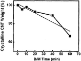
- Figure 4 is a graph for explaining the damage degree of the fine carbon material with respect to the ball mill process time.
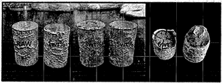
- RAW 5 is a material consisting only of aluminum material (RAW), aluminum-fine carbon material composite material (1wt%) having a content of fine carbon material 1wt%, aluminum-fine carbon material composite having a content of fine carbon material 3wt% Molding and sintering of the material (3wt%), aluminum-fine carbon material composite material (5wt%) containing 5wt% of fine carbon materials and aluminum-fine carbon material composite material (5wt%) containing 5wt% of fine carbon materials One picture.
- RAW aluminum-fine carbon material composite material
- FIG. 9 is a photograph showing a confocal Raman (Witec, CRM 200) measurement result after extrusion.
- first and second may be used to describe various components, but the components should not be limited by the terms. The terms are used only for the purpose of distinguishing one component from another.
- the first component may be referred to as the second component, and similarly, the second component may also be referred to as the first component.
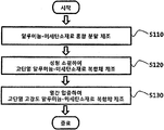
- FIG. 1 is a flowchart illustrating a method of manufacturing a high insulation high strength aluminum-microcarbon material composite according to an embodiment of the present invention.
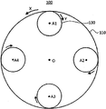
- 2 is a plan view for explaining the ball mill device
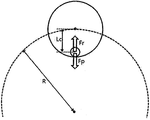
- Figure 3 is a schematic diagram for explaining the force acting on the ball mill ball injected into the ball mill container.
- fine carbon material fine graphite plates, fine graphite fibers, fine carbon fibers, carbon nanofibers, carbon nanotubes, or the like may be used.
- the fine carbon material cluster may be added in an amount of about 1 to 5 wt.% Based on the total weight. When the content of the fine carbon material cluster is less than 1 wt.%, The fine carbon material has a slight effect on the thermal and mechanical properties of the composite, and when the content of the fine carbon material cluster is more than 5 wt.%, The composite There is a problem that the mechanical properties of the is sharply lowered.
- the disk 110 may rotate in a first direction X with respect to a first central axis (hereinafter, referred to as an 'orbital axis') positioned at the center 'O' of the disk 110, and the ball mill container 130 may be rotated. Is coupled to the edge of the disk 110 and is located in a direction opposite to the first direction (X) with respect to a second central axis (hereinafter referred to as the 'rotation axis') located at the center 'A1' of the ball mill container 130. It can rotate in two directions (Y). That is, the ball mill container 130 may revolve with respect to the revolution axis by the rotation of the disc 110, and may rotate based on the rotation axis by the rotation of the ball mill container 130 itself.
- Y second central axis
- the disk 110 and the ball mill container 130 may be rotated such that the ball mill ball introduced into the ball mill container 130 applies a mechanical impact to the aluminum powders and the fine carbon material clusters.
- the ball mill ball introduced into the ball mill container 130 is rotated by the first centrifugal force Fr and the ball mill container 130 due to the revolution of the ball mill container 130.
- the second centrifugal force Fp is caused to act.
- the first centrifugal force Fr acts in the direction away from the ball axis
- the second centrifugal force Fp acts in the direction away from the axis.
- the magnitude or direction of action of the first and second centrifugal forces Fr and Fp depends on the position of the ball mill ball.
- the ball mill ball rotates in the same direction as the ball mill container 130 by the friction force between the ball mill ball and the wall surface of the ball mill container 130. Due to the action of these forces, the ball mill ball in the ball mill container 130 is moved by friction with the aluminum powders and the fine carbon material cluster or friction is caused by the rotation of the ball mill ball in contact with the aluminum powder and the fine carbon material cluster.
- Exercise that is, exercise to apply a mechanical impact force.
- the size of the micropores present in the interior of the composite is fine, it affects the heat transfer characteristics of the composite, but does not significantly affect the mechanical properties. In general, when the size of the pores present in the composite is more than 0.5mm it is reported that the mechanical properties of the composite is sharply lowered. Therefore, in the present invention, in order to prevent mechanical properties of the final aluminum-fine carbon material composite and to improve thermal insulation properties, the size of the micropores present in the aluminum-fine carbon material mixed powders is controlled to be several hundred nm or less. do.
- the ball mill ball controls the rotational speed of the disk 110 and the ball mill container 130 to apply a mechanical shear force to the aluminum-fine carbon material mixture.
- the orbital centrifugal force (Fr) acting on the ball mill ball located closest to the revolving axis of the ball mill vessel 130 may be represented by Equation 1 below, and the ball mill vessel 130 is located closest to the revolving axis of the internal space of the ball mill vessel 130.
- the rotating centrifugal force (Fp) acting on the ball mill ball may be expressed by the following Equation 2.
- Equation 1 and 2 'm' represents the weight of the ball mill ball, 'R' represents the distance between the revolution axis and the rotation axis, that is, the revolution radius, 'Lc' ball mill ball at the radius of the ball mill vessel
- w1 is the rotational angular velocity
- w2 is the rotational angular velocity
- 'w2 / w1' is the critical angular velocity ratio 'rc'
- the critical angular velocity ratio 'rc' may be derived from Equations 1 and 2 and may be expressed as Equation 3 below.
- the ratio of the rotation speed to the revolution speed of the ball mill container 130 may be controlled to be about 30 to 70% of the critical angular velocity ratio.
- the ratio of the rotation speed to the revolution speed (w2 / w1) is the critical angular velocity ratio ( less than about 70% of rc). That is, when the ratio of the rotational speed to the rotational speed (w2 / w1) exceeds 70% of the critical angular velocity ratio (rc), the influence of the centrifugal force due to the rotation increases, so that the ball mill ball is mainly composed of an aluminum-fine carbon material mixture. You have a conflicting exercise.
- the rotational speed of the ball mill ball itself is low, so that the mechanical shear force applied to the fine carbon material is too small, As a result, a problem may occur in that the mixture of the aluminum powder and the fine carbon material cannot be transformed into a constant plate shape.
- the mechanical shear force applied by the ball mill ball to the aluminum-fine carbonaceous material mixture is affected by the rotational speed of the ball mill ball itself, which is determined by the rotational speed of the ball mill container. That is, as the rotation speed of the ball mill container increases, the rotation speed of the ball mill ball itself increases.
- the inside of the ball mill vessel 110 is preferably maintained in an inert gas atmosphere during the ball mill process.
- the ball mill process may be performed for about 5 minutes to 6 hours, preferably about 5 to 40 minutes.
- an aluminum-fine carbon material mixed powder may be prepared.
- the damage degree of the fine carbon material may increase rapidly.
- Figure 4 is a graph for explaining the damage degree of the fine carbon material with respect to the ball mill process time.
- a mixture of 95 wt.% Aluminum powder and 5 wt.% Carbon nanotube clusters was used as a sample, and the ball milling process was performed under conditions of 300 rpm and 200 rpm, respectively.
- the weight ratio of crystalline carbon nanotubes was measured for 5 minutes, 10 minutes, 20 minutes, 40 minutes and 60 minutes. Decreasing the weight ratio of the crystalline carbon nanotubes means that the damage degree of the carbon nanotubes is increased.
- the size and morphology of the microcarbon material clusters have a great influence on the mechanical and thermal properties of the composite. For example, at the same volume fraction, the smaller the size of the microcarbon material and the more spherical than the spherical, the better the mechanical properties of the composite.
- the ball mill process is performed as described above, aluminum powders are initially pulverized by mechanical impact and friction with the ball mill balls, and are separated into main particles and satellite particles, and fine carbon material clusters are also pulverized to reduce its size. The shape is deformed into a plate shape and the cluster density is increased to reduce the internal pores. Subsequently, when the ball mill process is continuously performed, fine carbon material clusters adhere to the surface of the aluminum main particles, aluminum satellite particles are bonded to the main particles, and an aluminum-fine carbon material mixed powder close to the plate is produced.
- the aluminum-fine carbon material mixed powder is filled into a mold.
- the aluminum-fine carbon material mixed powders filled in the mold may be plastically deformed and sintered by sintering at a temperature of about 200 to 600 ° C. for about 1 minute to 1 hour.
- the aluminum-fine carbon material composite material is heated at a temperature of about 200 to 600 ° C. for about 1 minute to 1 hour. After heating, the extrusion can be performed using an extrusion die while applying a pressure of about 50 MPa to 700 MPa.
- micropores having a size of several tens of nm or less are uniformly distributed therein. Such micropores do not significantly affect the mechanical properties of the composite, whereas the thermal insulation properties of the composite are greatly improved.
- the fine pores have lower thermal conductivity than aluminum matrix or fine carbon material reinforcement.
- the micropores inside the composite are mainly formed inside the microcarbon material cluster, and are also formed at the interface between some aluminum matrix and the microcarbon material.
- the ball mill process was carried out using a steel ball mill (Taekyung Science), a 400g ball mill ball (zirconia), and a planetary mill (Model: Pulverisette 5) made of SKD 11 material. In order to prevent the argon (Ar) was purged after holding in a vacuum (10-2torr).
- the aluminum-fine carbon material mixture powder was put into a mold, and the upper and lower punches were fixed, and then compressed at a pressure of 700 MPa using a sintering molding machine, and then sintered at a temperature of 400 ° C. for about 2 minutes to produce an aluminum-fine carbon material composite material.
- a pressure of 700 MPa using a sintering molding machine
- the sintered aluminum fine carbon material composite material was maintained at a temperature of 550 ° C. for about 1 hour and extruded at a pressure of 600 MPa using an extruder. At this time, the temperature of the mold was 550 °C, the extrusion ratio was about 10.
- RAW 5 is a material consisting only of aluminum material (RAW), aluminum-fine carbon material composite material (1wt%) having a content of fine carbon material 1wt%, aluminum-fine carbon material composite having a content of fine carbon material 3wt% Molding and sintering of the material (3wt%), aluminum-fine carbon material composite material (5wt%) containing 5wt% of fine carbon materials and aluminum-fine carbon material composite material (5wt%) containing 5wt% of fine carbon materials One picture.
- RAW aluminum-fine carbon material composite material
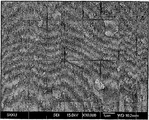
- Example 6 is an electron microscope (JEOL, JSM7000F) photograph of the aluminum-fine carbon material mixture prepared according to Example 1, which was observed at 10,000X after 2 hours of ball milling.
- carbon nanotubes are uniformly dispersed on the surface of the aluminum powder.
- Table 1 shows a sample composed only of aluminum (RAW), a sample of aluminum-fine carbon composite material (Al-1wt% CNT, Example 1) having a content of 1 wt% of fine carbon material, and 3 wt% of fine carbon material.
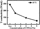
- Fig. 7 shows the measurement results, and Fig. 7 is a graph for explaining the thermal conductivity according to the content of the fine carbon material shown in Table 1.
- the thermal conductivity of the aluminum-fine carbon material composite (Example 1) having a content of the fine carbon material 1 wt% compared to the aluminum material (Raw) was reduced by 25.9%.
- the reduction in thermal conductivity can be interpreted as an increase in the thermal insulation effect.
- the thermal conductivity of the aluminum-fine carbon material composite (Example 2) having the content of the fine carbon material 3wt% and the aluminum-fine carbon material composite having the content of the fine carbon material 5wt% (Example 3) was 39.8%, respectively. , 48.5% decrease. That is, when the aluminum-fine carbon material composite is manufactured according to the embodiment of the present invention, it can be seen that the heat insulating property of the composite is improved as the content of the fine carbon material increases.
- FIG 8 is a photograph showing the shape after extrusion of the aluminum-fine carbon material composite
- Figure 9 is a photograph showing the confocal Raman (Witec, CRM 200) measurement results after extrusion.
- G mode shows the inherent peak of the carbon material as a yellow dot.
- Table 2 shows a sample of aluminum material (RAW), a sample of aluminum-fine carbon composite material (Al-1wt% CNT, Example 1) having a content of 1 wt% fine carbon material, and a content of 3 wt% fine carbon material.
- the hardness of the aluminum-fine carbon material composite sample (Al-3wt% CNT, Example 2) is shown, and FIG. 10 is a graph for explaining the hardness according to the content of the fine carbon material shown in Table 2.
- the specimen was measured using 1 ⁇ m alumina (Al 2 O 3) powder and then polished for 10 seconds at 100 g load using a Micro Vickers hardness tester (Mitutoyo).
- the hardness of the aluminum-fine carbon material composite (Example 1) having a content of 1 wt% of the fine carbon material compared to the aluminum material (Raw) is increased by 150.3%.
- the hardness of the aluminum-fine carbon material composite (Example 2) having a content of 3 wt% of the fine carbon material increased by 254.0%. As the content of the fine carbon material increases, it can be seen that the mechanical properties are significantly improved.
- Figure 11 is a cross-sectional scanning electron micrograph after the extrusion of Example 1.
- Table 3 shows a sample of a material consisting only of aluminum (RAW), a sample of aluminum-fine carbon composite material (Al-1wt% CNT, Example 1) having a content of 1 wt% of fine carbon material, and a content of fine carbon material of 3
- Sample of aluminum-fine carbon material composite at wt% Al-3wt% CNT, Example 2
- Sample of aluminum-fine carbon material composite at Alwt% 5wt% Al-5wt% CNT, Example 3
- Figure 12 is a graph for explaining the thermal conductivity according to the content of the fine carbon material shown in Table 3.
- the thermal conductivity of the aluminum-fine carbon material composite (Example 1) having a content of 1 wt% of the fine carbon material compared to the aluminum material (Raw) was reduced by 24.1%.
- the reduction in thermal conductivity can be interpreted as an increase in the thermal insulation effect.
- the thermal conductivity of the aluminum-fine carbon material composite (Example 2) having a content of 3 wt% microcarbon material and the aluminum-fine carbon material composite (Example 3) having a content of 5 wt% microcarbon material was 38.9%, respectively. , 46.5% decrease. That is, when manufacturing the aluminum-fine carbon material composite according to an embodiment of the present invention, it can be seen that the heat insulating properties of the composite can be improved.
- an aluminum-fine carbon material composite can be manufactured in a large amount through a relatively simple process.
- the aluminum-fine carbon material composite prepared according to the above-described manufacturing method has a fine carbon material uniformly dispersed in aluminum, thereby increasing heat insulating properties and enhancing mechanical properties. Therefore, when the high-insulation high-strength aluminum-fine carbon material composite is used as a structural material, such as explosion-proof windows and aluminum windows for curtain wells of high-rise buildings, it is possible to produce a structural material with excellent heat insulating properties and light weight. In addition, it can be used as a thermal insulation structure for high temperature because of its excellent thermal insulation properties.
Landscapes
- Engineering & Computer Science (AREA)
- Manufacturing & Machinery (AREA)
- Mechanical Engineering (AREA)
- Manufacture Of Alloys Or Alloy Compounds (AREA)
- Powder Metallurgy (AREA)
Abstract
알루미늄-미세탄소재료 복합체의 제조방법이 개시된다. 알루미늄-미세탄소재료 복합체를 제조하기 위하여, 우선 알루미늄 분말과 미세탄소재료를 분산시켜 알루미늄-미세탄소재료 혼합 분말을 제조한다. 이어서, 분산된 알루미늄-미세탄소재료 혼합 분말들을 소결성형한다. 그 후, 소결성형된 알루미늄-미세탄소재료 복합체를 열간 압출한다. 이러한 알루미늄-미세탄소재료 복합체의 제조방법에 따르면, 단열특성이 우수하고 기계적 특성이 우수한 알루미늄-미세탄소재료 복합체를 비교적 간단한 공정을 통해 제조할 수 있다.
Description
본 발명은 고단열 및 고강도 특성을 갖는 알루미늄-미세탄소재료 복합체의 제조방법 및 이에 의해 제조된 알루미늄-미세탄소재료 복합체에 관한 것이다.
최근 지속적인 경제 발전과 인구증가로 인하여 도심 재개발 사업이 활발히 진행되고 있고, 이로 인하여 대형 고층 빌딩의 신축이 증가하고 있다. 대형 고층 빌딩 등의 건물들은 냉난방, 조명 등에 많은 에너지를 소모하므로, 이중 상당량의 에너지는 건물들의 창호로 낭비되고 있다. 이에 창호로 낭비되는 에너지를 줄이기 위해 단열 효과가 높은 창호를 개발하여 에너지 효율을 높일 필요가 점점 더 절실해 지고 있다. 예를 들면, 여름철에는 햇빛의 열기를 차단하여 건물의 냉방부하를 줄여주고 겨울철에는 건물 내부의 난방 열기를 외부로의 손실을 막아 난방부하를 줄여주는 단열창호 개발이 절실히 요구되고 있다.
현재 단열 성능을 높이기 위해 PVC 소재의 창호를 주로 사용되고 있으나, PVC 창호의 낮은 기계적인 특성 때문에 고층건물의 방폭창 및 커튼웰에 사용이 불가하므로 고층빌딩에는 주로 알루미늄 창호가 사용되고 있다. 하지만 알루미늄 창호는 열전도도가 약 230W/mK 정도로 매우 높으므로, 알루미늄 창호를 통한 열 손실이 많은 문제점이 있다.
이러한 문제점을 개선하기 위하여 단열 특성이 우수하면서도 기계적 강도가 높은 알루미늄 복합 소재에 대한 연구가 활발히 진행되고 있다.
본 발명의 일 목적은 미세탄소재료가 균일하게 분산되어 있는 알루미늄-미세탄소재료 복합체를 제조하는 방법을 제공하는 것이다.
본 발명의 다른 목적은 상기의 방법에 의해 제조된 고단열 고강도 알루미늄-미세탄소재료 복합체를 제공하는 것이다.
상술한 본 발명의 목적을 달성하기 위한 알루미늄-미세탄소재료 복합체의 제조 방법은 알루미늄 분말들에 미세탄소재료를 분산시켜 알루미늄-미세탄소재료 혼합 분말을 제조하는 단계; 상기 알루미늄-미세탄소재료 혼합 분말들에 고온가압하에서 소결성형하여 고단열 알루미늄-미세탄소재료 복합체를 형성하는 단계; 및 상기 소결성형된 고단열 알루미늄-미세탄소재료 복합체를 열간 압출하여 고단열 고강도 알루미늄-미세탄소재료 복합체를 성형 및 제조하는 단계를 포함할 수 있다.
상기 알루미늄-미세탄소재료 혼합 분말을 제조하는 단계는 제1 방향으로 회전 가능한 디스크에 상기 제1 방향과 반대 방향인 제2 방향으로 회전 가능하게 결합된 볼밀 용기에 상기 알루미늄-탄소 혼합 분말들 및 볼밀볼을 투입하는 단계; 및 상기 볼밀볼이 상기 볼밀 용기의 벽면과 마찰하여 상기 볼밀볼 자체가 회전하여 상기 알루미늄-탄소 혼합 분말들에 기계적 충격을 인가하도록 상기 디스크 및 상기 볼밀 용기를 소정 시간동안 회전시키는 단계를 포함할 수 있다. 상기 디스크의 회전속도에 대한 상기 볼밀 용기의 회전 속도의 비는 임계 각속도 비의 30% 이상 70% 이하일 수 있다. 상기 디스크의 회전 속도는 50 rpm 이상 500 rpm 이하일 수 있다.
상기 미세탄소재료는 미세흑연판, 미세흑연섬유, 미세탄소섬유, 탄소나노섬유 및 탄소나노튜브로 이루어진 그룹 중 적어도 하나를 포함할 수 있다. 상기 알루미늄 분말들은 상기 탄소재료가 상기 알루미늄 분말들의 중량에 대해 약 0.1 내지 50 wt% 정도가 되도록 첨가될 수 있다.
상기 알루미늄-미세탄소재료 혼합 분말들을 소결성형하여 고단열 알루미늄-미세탄소재료 복합체를 형성하는 단계는 상기 분산된 알루미늄-미세탄소재료 혼합 분말들을 금형에 충진하는 단계; 및 상기 금형에 충진된 상기 분산된 알루미늄-미세탄소재료 혼합 분말들에 50MPa 내지 700MPa의 압력을 인가한 상태에서 상기 분산된 알루미늄-미세탄소재료 혼합 분말들을 200 내지 600℃의 온도로 가열하는 단계를 포함할 수 있다.
상기 알루미늄-미세탄소재료 복합체를 열간 압출하여 고단열 고강도 알루미늄-미세탄소재료 복합체를 성형 및 제조하는 단계는 상기 알루미늄-미세탄소재료 복합체를 200 내지 600℃의 온도로 가열하는 단계; 가열된 알루미늄-미세탄소재료 복합체를 압출 금형에 삽입하는 단계, 및 상기 압출 금형에 50MPa 내지 700MPa의 압력을 인가하여 압출하는 단계를 포함할 수 있다.
본 발명의 실시예에 따라 고단열 고강도 알루미늄-미세탄소재료 복합체를 제조하는 경우, 미세탄소재료 클러스터(cluster)가 균일하게 분산되어 있어 단열특성이 우수한 알루미늄-미세탄소재료 복합체를 제조할 수 있다. 또한 압출을 통한 성형성이 우수하여 여러 분야에서 적용이 용이하다. 이러한 고단열 고강도 알루미늄-미세탄소재료 복합체는 무게가 가볍고, 단열특성이 우수하여 현재 사용되는 건축 내외부 자제에 적용가능하며, 고강도 창틀용 창호 소재 및 단열특성이 요구되는 자동차, 항공기, 우주선, 선박 등의 소재로서도 활용될 수 있다.
도 1은 본 발명의 실시예에 따른 고단열 고강도 알루미늄-미세탄소재료 복합체의 제조방법을 설명하기 위한 순서도이다.
도 2는 볼밀 장치를 설명하기 위한 도면이고,
도 3은 볼밀 용기 내부에 투입된 볼밀볼에 작용하는 힘을 설명하기 위한 도면이다.
도 4는 볼밀공정 시간에 대한 미세탄소재료의 손상도를 설명하기 위한 그래프이다.
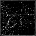
도 5는 알루미늄 재료로만 이루어진 재료(RAW), 미세탄소재료의 함량이 1 wt%인 알루미늄-미세탄소재료 복합재료(1wt%), 미세탄소재료의 함량이 3 wt%인 알루미늄-미세탄소재료 복합재료(3wt%), 미세탄소재료의 함량이 5wt%인 알루미늄-미세탄소재료 복합재료(5wt%) 및 미세탄소재료의 함량이 5wt%인 알루미늄-미세탄소재료 복합재료(5wt%)를 성형소결한 사진들이다.
도 6은 실시예 1에 따라 제조된 알루미늄-미세탄소재료 혼합체의 전자현미경(JEOL, JSM7000F) 사진
도 7은 표 1에 나타난 미세탄소재료의 함량에 따른 열전도도를 설명하기 위한 그래프이다.
도 8은 알루미늄-미세탄소재료 복합체의 압출 후의 형상을 나타내는 사진이고,
도 9는 압출 후 공초점 라만(Witec, CRM 200)측정 결과를 나타내는 사진이다.
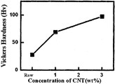
도 10은 표 2에 나타난 미세탄소재료의 함량에 따른 경도를 설명하기 위한 그래프이다.
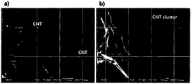
도 11은 실시예 1의 압출 후 파단면 주사전자현미경 사진들이다.
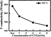
도 12는 표 3에 나타난 미세탄소재료의 함량에 따른 열전도도를 설명하기 위한 그래프이다.
이하, 첨부한 도면을 참조하여 본 발명의 실시예들에 대해 상세히 설명한다. 본 발명은 다양한 변경을 가할 수 있고 여러 가지 형태를 가질 수 있는 바, 특정 실시 예들에 대해서만 상세하게 설명하고자 한다. 그러나 이는 본 발명을 특정한 개시 형태에 대해 한정하려는 것이 아니며, 본 발명의 사상 및 기술 범위에 포함되는 모든 변경, 균등물 내지 대체물을 포함하는 것으로 이해되어야 한다.
제1, 제2 등의 용어는 다양한 구성요소들을 설명하는데 사용될 수 있지만, 상기 구성요소들은 상기 용어들에 의해 한정되어서는 안 된다. 상기 용어들은 하나의 구성요소를 다른 구성요소로부터 구별하는 목적으로만 사용된다. 예를 들어, 본 발명의 권리 범위를 벗어나지 않으면서 제1 구성요소는 제2 구성요소로 명명될 수 있고, 유사하게 제2 구성요소도 제1 구성요소로 명명될 수 있다.
본 출원에서 사용한 용어는 단지 특정한 실시 예를 설명하기 위해 사용된 것으로, 본 발명을 한정하려는 의도가 아니다. 단수의 표현은 문맥상 명백하게 다르게 뜻하지 않는 한, 복수의 표현을 포함한다. 본 출원에서, "포함하다" 또는 "가지다" 등의 용어는 명세서 상에 기재된 특징, 구성요소 등이 존재함을 지정하려는 것이지, 하나 또는 그 이상의 다른 특징들이나 구성요소 등이 존재하지 않거나 부가될 수 없음을 의미하는 것은 아니다.
다르게 정의되지 않는 한, 기술적이거나 과학적인 용어를 포함해서 여기서 사용되는 모든 용어들은 본 발명이 속하는 기술 분야에서 통상의 지식을 가진 자에 의해 일반적으로 이해되는 것과 동일한 의미를 가지고 있다. 일반적으로 사용되는 사전에 정의되어 있는 것과 같은 용어들은 관련 기술의 문맥 상 가지는 의미와 일치하는 의미를 가지는 것으로 해석되어야 하며, 본 출원에서 명백하게 정의하지 않는 한, 이상적이거나 과도하게 형식적인 의미로 해석되지 않는다.
도 1은 본 발명의 실시예에 따른 고단열 고강도 알루미늄-미세탄소재료 복합체의 제조방법을 설명하기 위한 순서도이다. 도 2는 볼밀 장치를 설명하기 위한 평면도이고, 도 3은 볼밀 용기 내부에 투입된 볼밀볼에 작용하는 힘을 설명하기 위한 모식도이다.
도 1을 참조하면, 본 발명의 실시예에 따라 알루미늄-미세탄소재료 복합체를 제조하기 위하여, 알루미늄 분말들에 미세탄소재료를 분산시켜 알루미늄-탄소 혼합 입자들을 제조한 후(S110), 알루미늄-탄소 혼합 입자들을 성형 소결하여 알루미늄-미세탄소재료 복합재료를 제조하며(S120), 이어서 알루미늄-미세탄소재료 복합재료를 열간 압출하여 고단열 고강도 알루미늄-미세탄소재료 복합체를 제조할 수 있다(S130).
알루미늄-탄소 혼합 입자들을 제조하기 위하여(S110), 우선 알루미늄 분말들에 미세탄소재료 클러스터(cluster)를 혼합할 수 있다. 일례로, 알루미늄 분말들의 평균직경은 약 50 내지 90㎛인 것이 바람직하고, 미세탄소재료 클러스터는 단면이 타원형 또는 원형인 형태로 약 2 내지 8㎛의 제1축 길이 및 약 0.5 내지 10㎛의 제2축 길이를 갖는 것이 바람직하다. 미세탄소재료 클러스터의 크기가 상기의 값보다 큰 경우, 복합체의 기계적 특성을 저하시키는 문제점이 발생할 수 있고, 미세탄소재료 클러스터의 크기가 상기의 값보다 작은 경우, 복합체의 단열 특성이 저하되는 문제점이 발생할 수 있다.
미세탄소재료로는 미세흑연판, 미세흑연섬유, 미세탄소섬유, 탄소나노섬유, 탄소나노튜브 등을 사용될 수 있다. 미세탄소재료 클러스터는 총 중량 대비 약 1 내지 5 wt.% 첨가될 수 있다. 미세탄소재료 클러스터의 함량이 1wt.% 미만인 경우, 미세탄소재료는 복합체의 열적 특성 및 기계적 특성에 미치는 영향이 미미한 문제점이 있고, 미세탄소재료 클러스터의 함량이 5 wt.%를 초과하는 경우, 복합체의 기계적 특성이 급격히 저하되는 문제점이 있다.
이어서, 볼밀 공정을 이용하여 알루미늄 분말들과 미세탄소재료 클러스터(cluster)의 혼합물로부터 알루미늄-미세탄소재료 혼합 분말을 제조할 수 있다.
도 1, 도 2 및 도 3을 참조하면, 디스크(110)에 회전 가능하게 결합된 볼밀 용기(130)에 알루미늄 분말들과 미세탄소재료 클러스터의 혼합물 및 볼밀볼을 투입한 후 볼밀 공정을 수행하여, 알루미늄 분말들과 미세탄소재료 클러스터의 혼합물에 기계적 충격을 인가할 수 있다.
디스크(110)는 디스크(110)의 중심 'O'에 위치하는 제1 중심축(이하 '공전축'이라 함)을 기준으로 제1 방향(X)으로 회전할 수 있고, 볼밀 용기(130)는 디스크(110)의 가장 자리에 결합되어 볼밀 용기(130)의 중심 'A1'에 위치하는 제2 중심축(이하 '자전축'이라 함)을 기준으로 제1 방향(X)과 반대 방향인 제2 방향(Y)으로 회전할 수 있다. 즉, 볼밀 용기(130)는 디스크(110)의 회전에 의해 공전축을 기준으로 공전(revolution)할 수 있고, 볼밀 용기(130) 자체의 회전에 의해 자전축을 기준으로 자전(rotation)할 수 있다.
볼밀볼의 재질은 특별히 제한되지 않으나, 알루미늄 분말들과 미세탄소재료들에 효과적으로 충격력을 인가하도록 지르코니아 재질로 된 볼밀볼을 사용할 수 있다. 볼밀볼은 알루미늄 분말들과 미세탄소재료 클러스터에 인가되어야 하는 충격력을 고려하여 약 3 내지 50mm의 직경을 가질 수 있다.
이어서, 볼밀 용기(130)에 투입된 볼밀볼이 알루미늄 분말들과 미세탄소재료 클러스터들에 기계적 충격을 인가하도록 디스크(110) 및 볼밀 용기(130)를 회전시킬 수 있다. 디스크(110) 및 볼밀 용기(130)가 회전하는 경우, 볼밀 용기(130) 내부에 투입된 볼밀볼에는 볼밀 용기(130)의 공전으로 인한 제1 원심력(Fr)과 볼밀 용기(130)의 자전으로 인한 제2 원심력(Fp)이 작용하게 된다. 제1 원심력(Fr)은 볼밀볼이 공전축으로부터 멀어지는 방향으로 작용하고, 제2 원심력(Fp)은 볼밀볼이 자전축으로부터 멀어지는 방향으로 작용한다. 이러한 제1 및 제2 원심력(Fr, Fp)의 크기 또는 작용방향은 볼밀볼의 위치에 따라 달라진다. 또한, 디스크(110)가 회전하는 상태에서 볼밀 용기(130)가 회전하는 경우, 볼밀볼과 볼밀 용기(130) 벽면 사이의 마찰력에 의해 볼밀볼이 볼밀 용기(130)와 동일한 방향으로 회전하게 된다. 이러한 힘들의 작용에 의해 볼밀 용기(130) 내의 볼밀볼은 알루미늄 분말들 및 미세탄소재료 클러스터와 충돌하는 운동을 하거나 알루미늄 분말들 및 미세탄소재료 클러스터와 접촉한 상태에서 해당 볼밀볼의 회전에 의해 마찰하는 운동, 즉, 기계적 충격력을 인가하는 운동을 할 수 있다.
볼밀볼에 의해 알루미늄 분말들과 미세탄소재료 클러스터들에 인가되는 기계적 충격력은 볼밀볼이 알루미늄 분말들 및 미세탄소재료 클러스터들을 가압하는 압력에 영향을 받는데, 이는 볼밀 용기(130)의 공전 속도에 영향을 받는다. 즉, 볼밀 용기(130)의 공전 속도가 증가할수록 볼밀볼이 알루미늄 분말들 및 미세탄소재료 클러스터를 가압하는 압력이 증가한다. 본 발명에 있어서는, 미세탄소재료 클러스터의 크기가 약 3㎛ 이하가 되고, 미세탄소재료의 손상도가 15% 이하가 되며, 클러스터 내부의 미세 기공이 약 수백 ㎚ 이하의 크기를 갖도록 하기 위하여, 디스크의 회전 속도는 약 50 내지 500 rpm이 되도록 조절될 수 있다. 복합체의 내부에 존재하는 미세기공의 크기가 미세한 경우, 복합체의 열전달 특성에는 영향을 미치나 기계적 특성에는 크게 영향을 미치지 않는다. 일반적으로 복합체 내부에 존재하는 기공의 크기가 0.5㎜ 이상인 경우 복합체의 기계적 특성에 급격한 저하된다고 보고되고 있다. 따라서, 본 발명의 경우, 최종 알루미늄-미세탄소재료 복합체의 기계적 특성 저하를 방지하고 단열 특성을 향상시키기 위하여, 알루미늄-미세탄소재료 혼합 분말들에 존재하는 미세 기공의 크기를 수백 ㎚ 이하가 되도록 제어한다.
본 발명에 있어서는, 볼밀볼이 알루미늄-미세탄소재료 혼합물에 기계적 전단력을 인가할 수 있도록 디스크(110)와 볼밀 용기(130)의 회전 속도를 제어한다. 볼밀 용기(130) 내부 공간 중 공전축에 가장 가깝게 위치한 볼밀볼에 작용하는 공전 원심력(Fr)은 하기 '식 1'로 표현될 수 있고, 볼밀 용기(130) 내부 공간 중 공전축에 가장 가깝게 위치한 볼밀볼에 작용하는 자전 원심력(Fp)은 하기 '식 2'로 표현될 수 있다.
[식 1]

[식 2]

상기 식 1 및 식 2에 있어서, 'm'은 볼밀볼의 무게를 나타내고, 'R'은 공전축과 자전축 사이의 거리, 즉, 공전 반경을 나타내고, 'Lc'는 볼밀 용기의 반경에서 볼밀볼의 반경을 뺀 값을 나타내고, 'w1'은 공전 각속도를 나타내며, 'w2'는 자전 각속도를 나타낸다.
공전축에 가장 가깝게 위치한 볼밀볼에 작용하는 공전 원심력(Fr)이 상기 볼밀볼에 작용하는 자전 원심력(Fp)과 동일한 경우에 있어서의 공전 각속도(w1)에 대한 자전 각속도(w2)의 비(ratio) 'w2/w1'를 임계 각속도 비 'rc'라 한다면, 임계 각속도 비 'rc'는 상기 '식 1' 및 '식 2'로부터 유도되어 하기 '식 3'과 같이 표현될 수 있다.
[식 3]

본 발명에 있어서, 볼밀 용기(130)의 공전 속도에 대한 자전 속도의 비는 임계 각속도 비의 약 30 내지 70%가 되도록 제어될 수 있다. 볼밀볼에 자전 원심력보다는 공전 원심력이 크게 작용하여 볼밀볼이 알루미늄-미세탄소재료 혼합물과 충돌하기 보다는 주로 기계적 전단력을 인가하기 위해서는 공전 속도에 대한 자전 속도의 비(w2/w1)가 임계 각속도 비(rc)의 약 70% 이하가 되어야 한다. 즉, 공전 속도에 대한 자전 속도의 비(w2/w1)가 임계 각속도 비(rc)의 70%를 초과하는 경우, 자전에 의한 원심력의 영향이 증가하여 볼밀볼이 주로 알루미늄-미세탄소재료 혼합물과 충돌하는 운동을 하게 된다. 또한, 공전 속도에 대한 자전 속도의 비(w2/w1)가 임계 각속도 비(rc)의 30% 미만인 경우, 볼밀볼 자체의 회전 속도가 낮아서 미세탄소재료에 인가되는 기계적 전단력이 너무 작아지게 되고, 그 결과 알루미늄 분말과 미세 탄소재료의 혼합물을 일정한 판 형상으로 변형시킬 수 없게 되는 문제점이 발생할 수 있다. 볼밀볼에 의해 알루미늄-미세탄소재료 혼합물에 인가되는 기계적 전단력은 볼밀볼 자체의 회전 속도에 영향을 받는데, 볼밀볼 자체의 회전 속도는 볼밀 용기의 자전 속도에 의해 결정된다. 즉, 볼밀 용기의 자전 속도가 증가할수록 볼밀볼 자체의 회전 속도가 증가한다.
알루미늄 분말들과 미세탄소재료 클러스터들이 산화되는 것을 방지하기 위하여, 볼밀 용기(110) 내부는 볼밀 공정 동안 비활성 기체 분위기로 유지되는 것이 바람직하다. 볼밀 공정은 약 5분 내지 6시간, 바람직하게는 약 5분 내지 40분 동안 수행될 수 있다. 상기의 과정으로 알루미늄-미세탄소재료 혼합 분말을 제조할 수 있다. 볼밀 공정 시간이 40분을 초과하는 경우, 미세탄소재료의 손상도가 급격히 증가할 수 있다.
도 4는 볼밀공정 시간에 대한 미세탄소재료의 손상도를 설명하기 위한 그래프이다. 도 4에 있어서, 샘플로는 알루미늄 분말 95 wt.%와 탄소나노튜브 클러스터5 wt.%의 혼합물을 사용하였고, 공전속도 및 자전속도는 각각 300rpm 및 200rpm의 조건으로 볼밀 공정을 수행하였으며, 볼밀 공정 시간 5분, 10분, 20분, 40분 및 60분에 대하여 결정성 탄소나노튜브의 중량 비율을 측정하였다. 결정성 탄소나노튜브의 중량 비율이 감소하는 것은 탄소나노튜브의 손상도가 증가하는 것을 의미한다.
도 4를 참조하면, 볼밀 공정 시간이 증가할수록 탄소나노튜브의 손상도가 증가함을 알 수 있고, 특히, 볼밀 공정 시간이 40분을 초과하는 경우, 탄소나노튜브의 손상도가 급격히 증가함을 알 수 있다.
알루미늄-미세탄소재료 복합체에 있어서, 미세탄소재료 클러스터의 크기, 형상(morphology)은 복합체의 기계적 열적 특성에 큰 영향을 미친다. 예를 들면, 같은 부피 분율에서 미세탄소재료의 크기가 작을수록 그리고 구상보다는 판상으로 존재할수록 복합체의 기계적 특성이 향상된다. 상기와 같은 볼밀 공정을 수행하면, 초기에는 볼밀볼들과의 기계적 충격 및 마찰에 의해 알루미늄 분말들은 분쇄되어 메인 입자와 위성 입자로 분리되고, 미세탄소재료 클러스터 역시 분쇄되어 그 크기가 감소되고, 그 형상이 판상으로 변형되며 클러스터 밀도가 증가하여 내부 기공의 감소하게 된다. 그 후, 계속적으로 볼밀 공정을 수행하면, 알루미늄 메인 입자 표면에 미세탄소재료 클러스터가 부착하게 되고 알루미늄 위성 입자가 메인 입자에 접합되며 판상에 가까운 알루미늄-미세탄소재료 혼합 분말이 제조된다.
이어서, 다시 도 1을 참조하면, 제조된 알루미늄-미세탄소재료 혼합 분말을 소결성형하여 알루미늄-미세탄소재료 복합재료를 제조하기 위하여(S120), 알루미늄-미세탄소재료 혼합분말들을 금형에 충진한 후, 약 50MPa 내지 700MPa의 압력을 인가한 상태에서 약 1분 내지 1시간 동안 약 200 내지 600℃의 온도로 소결하여 금형에 충진된 알루미늄-미세탄소재료 혼합분말들을 소성변형 및 소결 시킬 수 있다.
이어서, 알루미늄-미세탄소재료 복합재료를 열간 압출하여 알루미늄-미세탄소재료 복합체를 제조하기 위하여(S130), 알루미늄-미세탄소재료 복합재료를 약 1 분 내지 1시간 동안 약 200 내지 600℃의 온도로 가열한 후, 압출 금형을 이용하여 약 50MPa 내지 700MPa의 압력을 인가한 상태에서 압출할 수 있다.
본 발명의 실시예에 따라 제조된 알루미늄-미세탄소재료 복합체의 경우, 내부에 수십 nm 이하의 크기를 갖는 미세기공이 균일하게 분포한다. 이러한 미세 기공은 복합체의 기계적 특성에는 크게 영향을 미치지 않음에 반해, 복합체의 단열 특성은 크게 향상시킨다. 미세 기공은 알루미늄 매트릭스나 미세탄소재료 강화제에 비해 열전도도가 낮기 때문이디. 복합체 내부의 미세 기공은 주로 미세탄소재료 클러스터 내부에 형성되고, 일부 알루미늄 매트릭스와 미세탄소재료의 계면에서도 형성된다.
알루미늄-미세탄소재료 복합체의 단열 특성은 미세탄소재료 클러스터 내부에 존재하는 미세 기공에 의해 많은 영향을 받는데, 알루미늄-미세탄소재료 복합체의 단열 특성을 향상시키기 위해서는 미세탄소재료 클러스터를 균일하게 분포시키는 것 뿐만 아니라 미세탄소재료 클러스터 내부의 기공을 균일하게 제어하는 것이 요구된다. 본 발명에 있어서는 알루미늄 분말과 미세탄소재료 클러스터의 크기를 제어하고, 볼밀 공정의 조건을 제어함으로써 미세탄소재료 클러스터를 복합체 내부에 균일하게 분포시킬 뿐만 아니라 미세탄소재료 클러스터 내부의 기공을 균일하게 형성할 수 있고, 그 결과 본 발명에 따라 제조된 알루미늄-미세탄소재료 복합체는 우수한 단열 특성을 가질 뿐만 아니라 고강도의 기계적 특성을 갖는다.
이하 본 발명의 실시예를 참조하여 본 발명에 대해 구체적으로 설명한다. 다만, 본 발명은 하기의 실시예들에 한정되는 것은 아니다.
[실시예 1, 2 및 3]
알루미늄 분말과 미세탄소재료 클러스터를 혼합한 후 볼밀 공정을 이용하여 알루미늄-미세탄소재료 혼합 분말들을 제조하였다. 전체 중량에 대해, 미세탄소재료 클러스터는 1wt%(실시예 1), 3wt%(실시예 2), 5wt%(실시예 3) 만큼 각각 첨가되었다. 알루미늄 분말로는 삼전화학사에서 구매한 크기 약 70㎛의 알루미늄 분말을 사용하였고, 미세탄소재료로는 약 10 내지 20㎚의 두께 및 약 10 내지 20㎛의 길이를 갖는 다중벽 탄소나노튜브(한화나노텍에서 구매한 Model CM95)를 사용하였다. 볼밀 공정은 SKD 11 소재로 제조된 강철 볼밀 자(태명과학), 400g의 볼밀볼(지르코니아), planetary mill(Model : Pulverisette 5)을 이용하여 수행되었고, 볼밀 공정동안 볼밀 자 내부는 알루미늄의 산화를 막기 위해 진공(10-2torr)에서 유지 후 아르곤(Ar)을 퍼징한 상태를 유지하였다.
이어서, 알루미늄-미세탄소재료 혼합 분말들을 금형에 넣고 상하부 펀치를 고정 시킨 뒤 소결성형 장치를 이용하여 700MPa의 압력으로 압축한 후, 400℃의 온도에서 약 2분 소결하여 알루미늄-미세탄소재료 복합재료를 제조하였다.
이어서, 소결성형한 알루미늄-미세탄소재료 복합재료를 550℃의 온도에서 약 1시간 유지한 뒤 압출기를 이용하여 600MPa의 압력으로 압출하였다. 이때 금형의 온도는 550℃이었으며, 압출비는 약 10이었다.
[실험예 1]- 열적 기계적 특성 평가
도 5는 알루미늄 재료로만 이루어진 재료(RAW), 미세탄소재료의 함량이 1 wt%인 알루미늄-미세탄소재료 복합재료(1wt%), 미세탄소재료의 함량이 3 wt%인 알루미늄-미세탄소재료 복합재료(3wt%), 미세탄소재료의 함량이 5wt%인 알루미늄-미세탄소재료 복합재료(5wt%) 및 미세탄소재료의 함량이 5wt%인 알루미늄-미세탄소재료 복합재료(5wt%)를 성형소결한 사진들이다.
도 5를 참조하면, 미세탄소재료의 함량이 6 wt.%인 경우 미세탄소재료의 함량이 너무 많아 소결이 이루어지지 않음을 확인할 수 있다. 즉, 미세탄소재료의 함량이 5 wt.%를 초과하는 경우 소결 성형할 수 없는 문제점이 발생하나, 미세탄소재료의 함량이 5 wt.% 이하인 경우 양호하게 소결 성형될 수 있음을 알 수 있다.
도 6은 실시예 1에 따라 제조된 알루미늄-미세탄소재료 혼합체의 전자현미경(JEOL, JSM7000F) 사진으로, 2시간 볼 밀 후 10,000X에서 관측한 전자현미경 사진이다.
도 6을 참조하면, 알루미늄 분말의 표면에 탄소나노튜브가 균일하게 분산되어 있는 것을 확인할 수 있다.
표 1은 알루미늄 재료로만 이루어진 샘플(RAW), 미세탄소재료의 함량이 1 wt%인 알루미늄-미세탄소재료 복합체 샘플(Al-1wt%CNT, 실시예 1), 미세탄소재료의 함량이 3 wt%인 알루미늄-미세탄소재료 복합체 샘플(Al-3wt%CNT, 실시예 2) 및 미세탄소재료의 함량이 5wt%인 알루미늄-미세탄소재료 복합체의 샘플(Al-5wt%CNT, 실시예 3)의 열전도도를 측정한 결과를 나타내고, 도 7은 표 1에 나타난 미세탄소재료의 함량에 따른 열전도도를 설명하기 위한 그래프이다. 샘플의 열적 특성을 측정하기 위해 시편은 지름 12.5㎜, 두께 2㎜로 가공하여 열전도측정기(NETZCH, Laser Flash Apparatus 457)를 이용하여 상온(약 25℃)에서 열전도도를 측정하였다.
표 1
| Sample | Test Temp.(℃) | 열전도도(W/mK) | 변화률(%) |
| Raw | 25.9 | 245.0 | - |
| Al-1wt%CNT | 24.7 | 181.6 | - 25.9 |
| Al-3wt%CNT | 25.6 | 147.5 | - 39.8 |
| Al-5wt%CNT | 25.1 | 126.1 | - 48.5 |
표 1 및 도 7을 참조하면, 알루미늄 재료(Raw)에 비해 미세탄소재료 1wt%의 함량을 가지는 알루미늄-미세탄소재료 복합체(실시예 1)이 열전도도가 25.9% 감소한 것을 확인할 수 있다. 열전도도의 감소는 단열효과의 증대로 해석할 수 있다. 또한, 미세탄소재료 3wt%의 함량을 가지는 알루미늄-미세탄소재료 복합체(실시예 2)와 미세탄소재료 5wt%의 함량을 가지는 알루미늄-미세탄소재료 복합체(실시예 3)의 열전도도는 각각 39.8%, 48.5% 감소하는 것을 확인할 수 있다. 즉, 본 발명의 실시예에 따라 알루미늄-미세탄소재료 복합체가 제조되는 경우, 미세탄소재료의 함량이 증가할수록 복합체의 단열 특성이 향상됨을 알 수 있다.
도 8은 알루미늄-미세탄소재료 복합체의 압출 후의 형상을 나타내는 사진이고, 도 9는 압출 후 공초점 라만(Witec, CRM 200)측정 결과를 나타내는 사진이다. 공초점 라만 측정시 G mode는 탄소재료 고유의 피크(peak)를 노란색 점으로 나타난다.
도 9을 참조하면, 압출 후에도 미세탄소재료가 균일하게 분산되어 있는 것을 알 수 있다.
표 2는 알루미늄 재료의 샘플(RAW), 미세탄소재료의 함량이 1 wt%인 알루미늄-미세탄소재료 복합체 샘플(Al-1wt%CNT, 실시예 1) 및 미세탄소재료의 함량이 3 wt%인 알루미늄-미세탄소재료 복합체 샘플(Al-3wt%CNT, 실시예 2)의 경도를 측정한 결과를 나타내고, 도 10은 표 2에 나타난 미세탄소재료의 함량에 따른 경도를 설명하기 위한 그래프이다. 샘플의 기계적 특성을 측정하기 위해 시편은 1㎛ 알루미나(Al2O3) 분말을 이용하여 폴리싱 후 마이크로 비커스 경도계(Mitutoyo)를 이용하여 100g 하중으로 10초간 측정하였다.
표 2
| Sample | 경도(Hv) | 변화률(%) |
| Raw | 27.6 | - |
| Al-1wt%CNT | 69.0 | + 150.3 |
| Al-3wt%CNT | 97.6 | + 254.0 |
표 2 및 도 10을 참조하면, 알루미늄 재료(Raw)에 비해 미세탄소재료 1wt%의 함량을 가지는 알루미늄-미세탄소재료 복합체(실시예 1)이 경도가 150.3% 증가한 것을 확인할 수 있다. 또한, 미세탄소재료 3wt%의 함량을 가지는 알루미늄-미세탄소재료 복합체(실시예 2)의 경도는 254.0% 증가한 것을 확인할 수 있다. 미세탄소재료의 함량의 증가함에 따라 기계적 특성이 현저하게 향상된 것을 확인할 수 있다.
도 11는 실시예 1의 압출 후 파단면 주사전자현미경 사진들이다.
도 11a를 참조하면, 탄소나노튜브가 알루미늄 표면에 고르게 분산되어 있는 것을 확인할 수 있다(전자현미경 150,000X). 알루미늄에 고르게 분산된 탄소나노튜브는 소성변형 시 발생하는 전위의 움직임을 막아 기계적 특성을 증가 시킨다.
도 11b를 참조하면, 탄소나노튜브는 주로 클러스터(cluster)로 존재함을 알 수 있다(전자현미경 50,000X). 이때 탄소나노튜브 클러스터(cluster) 내부에는 수 나노미터(㎚)의 미세기공(fine-pore)이 존재하게 된다. 이 미세기공에 의해 열전도도는 낮아지게 된다. 이는 표 1의 값과 정확히 부합되는 결과이다.
[실험예 2]
실험예 2에서는 고온에서의 열전도도 변화를 측정하기 위하여 알루미늄으로만 이루어진 샘플(RAW), 미세탄소재료의 함량이 1 wt%인 알루미늄-미세탄소재료 복합체 샘플(Al-1wt%CNT, 실시예 1) 및 미세탄소재료의 함량이 3 wt%인 알루미늄-미세탄소재료 복합체 샘플(Al-3wt%CNT, 실시예 2)과 미세탄소재료의 함량이 5wt%인 알루미늄-미세탄소재료 복합체의 샘플(Al-5wt%CNT, 실시예 3)의 열전도도를 약 100℃에서 측정하였다. 시편의 크기와 측정장비는 실험예 1과 동일하게 하였다.
표 3은 알루미늄으로만 이루어진 재료의 샘플(RAW), 미세탄소재료의 함량이 1 wt%인 알루미늄-미세탄소재료 복합체 샘플(Al-1wt%CNT, 실시예 1), 미세탄소재료의 함량이 3 wt%인 알루미늄-미세탄소재료 복합체 샘플(Al-3wt%CNT, 실시예 2) 및 미세탄소재료의 함량이 5wt%인 알루미늄-미세탄소재료 복합체의 샘플(Al-5wt%CNT, 실시예 3)의 열전도도를 측정한 결과를 나타내고, 도 12는 표 3에 나타난 미세탄소재료의 함량에 따른 열전도도를 설명하기 위한 그래프이다.
표 3
| Sample | Test Temp.(℃) | 열전도도(W/mK) | 변화률(%) |
| Raw | 99.8 | 241.7 | - |
| Al-1wt%CNT | 99.9 | 183.5 | - 24.1 |
| Al-3wt%CNT | 99.7 | 147.7 | - 38.9 |
| Al-5wt%CNT | 100.0 | 129.4 | - 46.5 |
표 3 및 도 12를 참조하면, 알루미늄 재료(Raw)에 비해 미세탄소재료 1wt%의 함량을 가지는 알루미늄-미세탄소재료 복합체(실시예 1)이 열전도도가 24.1% 감소한 것을 확인할 수 있다. 열전도도의 감소는 단열효과의 증대로 해석할 수 있다. 또한, 미세탄소재료 3wt%의 함량을 가지는 알루미늄-미세탄소재료 복합체(실시예 2)와 미세탄소재료 5wt%의 함량을 가지는 알루미늄-미세탄소재료 복합체(실시예 3)의 열전도도는 각각 38.9%, 46.5% 감소하는 것을 확인할 수 있다. 즉, 본 발명의 실시예에 따라 알루미늄-미세탄소재료 복합체를 제조하는 경우, 복합체의 단열 특성을 향상시킬 수 있음을 알 수 있다.
상술한 알루미늄-미세탄소재료 복합체의 제조방법에 따르면, 비교적 간단한 공정을 통해 대량적으로 알루미늄-미세탄소재료 복합체를 제조할 수 있다. 또한, 상기의 제조방법에 따라 제조된 알루미늄-미세탄소재료 복합체는 알루미늄 내에 미세탄소재료가 균일하게 분산되어 이로 인한 단열 특성의 증가와 강화된 기계적 특성을 가진다. 따라서, 상기 고단열 고강도 알루미늄-미세탄소재료 복합체는 고층건물의 방폭창 및 커튼웰용 알루미늄 창호 등과 같이 구조용 재료로 사용하는 경우, 단열 특성이 우수하고 경량화 된 구조재를 제조할 수 있다. 또한 고온에서도 단열 특성이 우수하여 고온용 단열 구조제로 사용이 가능하다.
상기에서는 본 발명의 바람직한 실시예를 참조하여 설명하였지만, 해당 기술 분야의 숙련된 당업자는 하기의 특허 청구 범위에 기재된 본 발명의 사상 및 영역으로부터 벗어나지 않는 범위 내에서 본 발명을 다양하게 수정 및 변경시킬 수 있음을 이해할 수 있을 것이다.
Claims (9)
- 알루미늄 분말들에 미세탄소재료 클러스터를 분산시켜 알루미늄-미세탄소재료 혼합 분말을 제조하는 단계;상기 알루미늄-미세탄소재료 혼합 분말들을 소결성형하여 알루미늄-미세탄소재료 복합재료를 제조하는 단계; 및상기 알루미늄-미세탄소재료 복합재료를 열간 압출하여 알루미늄-미세탄소재료 복합체를 제조하는 단계를 포함하는 고단열 고강도 알루미늄-미소탄소재료 복합체의 제조 방법.
- 제1항에 있어서, 상기 미세탄소재료는 미세흑연판, 미세흑연섬유, 미세탄소섬유, 탄소나노섬유 및 탄소나노튜브로 이루어진 그룹 중에서 선택된 적어도 하나를 포함하는 것을 특징으로 하는 고단열 고강도 알루미늄-미세탄소재료 복합체의 제조 방법.
- 제2항에 있어서, 상기 미세탄소재료 클러스터는 상기 혼합 분말 총 중량 대비 1 내지 5 wt.%인 것을 특징으로 하는 알루미늄-미세탄소재료 복합체의 제조 방법.
- 제1항에 있어서, 상기 알루미늄 분말들의 평균직경은 약 50 내지 90㎛이고, 상기 미세탄소재료 클러스터는 단면이 타원형 또는 원형인 형태를 갖고, 제1축에 따른 길이가 2 내지 8㎛이고, 제1축에 수직한 제2축에 따른 길이가 0.5 내지 10㎛인 것을 특징으로 하는 고단열 고강도 알루미늄-미세탄소재료 복합체의 제조 방법.
- 제1항에 있어서, 상기 알루미늄-미세탄소재료 혼합 분말을 제조하는 단계는 볼밀 용기가 공전 및 자전하는 볼밀 공정을 이용하여 수행되고,상기 볼밀 용기의 공전 속도는 50 rpm 이상 500 rpm 이하인 것을 특징으로 하는 고단열 고강도 알루미늄-미세탄소재료 복합체의 제조 방법.
- 제5항에 있어서, 상기 볼밀 공정은 5분 내지 6시간 수행되고,상기 볼밀 공정 후의 상기 알루미늄-미세탄소재료 혼합 분말은 3㎛ 이하의 크기를 갖는 상기 미세탄소재료 클러스터를 포함하는 것을 특징으로 하는 고단열 고강도 알루미늄-미세탄소재료 복합체의 제조 방법.
- 제1항에 있어서, 상기 알루미늄-미세탄소재료 복합재료를 제조하는 단계는,상기 알루미늄-미세탄소재료 혼합 분말들을 금형에 충진하는 단계; 및상기 금형에 충진된 상기 알루미늄-미세탄소재료 혼합 분말들을 50MPa 내지 700MPa의 압력을 인가한 상태에서 200 내지 600℃의 온도로 가열하는 단계를 포함하는 것을 특징으로 하는 고단열 고강도 알루미늄-미세탄소재료 복합체의 제조 방법.
- 제1항에 있어서, 알루미늄-미세탄소재료 복합체를 제조하는 단계는,상기 알루미늄-미세탄소재료 복합재료를 200 내지 600℃의 온도로 가열하는 단계;가열된 상기 알루미늄-미세탄소재료 복합재료를 압출 금형에 삽입하는 단계; 및상기 압출 금형에 50MPa 내지 700MPa의 압력을 인가하여 상기 알루미늄-미세탄소재료 복합재료를 압출하는 단계를 포함하는 것을 특징으로 하는 고단열 고강도 알루미늄-미세탄소재료 복합체의 제조 방법.
- 제1항 내지 제8항 중 어느 한 항의 방법으로 제조된 고단열 고강도 알루미늄-미세탄소재료 복합체.
Applications Claiming Priority (2)
| Application Number | Priority Date | Filing Date | Title |
|---|---|---|---|
| KR20130017263A KR20140115399A (ko) | 2013-02-19 | 2013-02-19 | 고단열 및 고강도 특성을 갖는 알루미늄-미세탄소재료 복합체의 제조방법 및 이에 의해 제조된 알루미늄-미세탄소재료 복합체 |
| KR10-2013-0017263 | 2013-02-19 |
Publications (1)
| Publication Number | Publication Date |
|---|---|
| WO2014129695A1 true WO2014129695A1 (ko) | 2014-08-28 |
Family
ID=51391464
Family Applications (1)
| Application Number | Title | Priority Date | Filing Date |
|---|---|---|---|
| PCT/KR2013/002288 Ceased WO2014129695A1 (ko) | 2013-02-19 | 2013-03-20 | 고단열 및 고강도 특성을 갖는 알루미늄-미세탄소재료 복합체의 제조방법 및 이에 의해 제조된 알루미늄-미세탄소재료 복합체 |
Country Status (2)
| Country | Link |
|---|---|
| KR (1) | KR20140115399A (ko) |
| WO (1) | WO2014129695A1 (ko) |
Cited By (1)
| Publication number | Priority date | Publication date | Assignee | Title |
|---|---|---|---|---|
| CN117926084A (zh) * | 2024-02-26 | 2024-04-26 | 山东省科学院新材料研究所 | 一种高强高导热Cp/Al复合材料及其制备方法与应用 |
Families Citing this family (1)
| Publication number | Priority date | Publication date | Assignee | Title |
|---|---|---|---|---|
| JP7160818B2 (ja) | 2017-08-31 | 2022-10-25 | 宇部エクシモ株式会社 | 黒色粉体及びその製造方法 |
Citations (5)
| Publication number | Priority date | Publication date | Assignee | Title |
|---|---|---|---|---|
| KR20090075651A (ko) * | 2009-06-08 | 2009-07-08 | 성균관대학교산학협력단 | 알루미늄과 탄소재료 간의 공유결합을 형성하는 방법, 알루미늄과 탄소재료 복합체를 제조하는 방법 및 그 방법에 의하여 제조된 알루미늄과 탄소재료 복합체 |
| JP2010159445A (ja) * | 2009-01-07 | 2010-07-22 | Shinshu Univ | 金属粒子と炭素粉末の混合方法、金属・炭素複合材料の製造方法および金属・炭素複合材料 |
| KR20120001890A (ko) * | 2010-06-30 | 2012-01-05 | 연세대학교 산학협력단 | 탄소나노튜브 또는 탄소 섬유가 네트워크 구조를 형성한 금속기지 복합재 제조 방법 및 그 복합재 |
| JP2012153944A (ja) * | 2011-01-26 | 2012-08-16 | Shinko Electric Ind Co Ltd | 金属複合材料の製造方法、金属複合材料、放熱部品の製造方法及び放熱部品 |
| KR20130000647A (ko) * | 2011-06-23 | 2013-01-03 | 권한상 | 알루미늄 및 카본나노튜브를 이용한 전력용 복합 선재 제조방법 및 그것에 의해 제조된 제품 |
-
2013
- 2013-02-19 KR KR20130017263A patent/KR20140115399A/ko not_active Ceased
- 2013-03-20 WO PCT/KR2013/002288 patent/WO2014129695A1/ko not_active Ceased
Patent Citations (5)
| Publication number | Priority date | Publication date | Assignee | Title |
|---|---|---|---|---|
| JP2010159445A (ja) * | 2009-01-07 | 2010-07-22 | Shinshu Univ | 金属粒子と炭素粉末の混合方法、金属・炭素複合材料の製造方法および金属・炭素複合材料 |
| KR20090075651A (ko) * | 2009-06-08 | 2009-07-08 | 성균관대학교산학협력단 | 알루미늄과 탄소재료 간의 공유결합을 형성하는 방법, 알루미늄과 탄소재료 복합체를 제조하는 방법 및 그 방법에 의하여 제조된 알루미늄과 탄소재료 복합체 |
| KR20120001890A (ko) * | 2010-06-30 | 2012-01-05 | 연세대학교 산학협력단 | 탄소나노튜브 또는 탄소 섬유가 네트워크 구조를 형성한 금속기지 복합재 제조 방법 및 그 복합재 |
| JP2012153944A (ja) * | 2011-01-26 | 2012-08-16 | Shinko Electric Ind Co Ltd | 金属複合材料の製造方法、金属複合材料、放熱部品の製造方法及び放熱部品 |
| KR20130000647A (ko) * | 2011-06-23 | 2013-01-03 | 권한상 | 알루미늄 및 카본나노튜브를 이용한 전력용 복합 선재 제조방법 및 그것에 의해 제조된 제품 |
Cited By (1)
| Publication number | Priority date | Publication date | Assignee | Title |
|---|---|---|---|---|
| CN117926084A (zh) * | 2024-02-26 | 2024-04-26 | 山东省科学院新材料研究所 | 一种高强高导热Cp/Al复合材料及其制备方法与应用 |
Also Published As
| Publication number | Publication date |
|---|---|
| KR20140115399A (ko) | 2014-10-01 |
Similar Documents
| Publication | Publication Date | Title |
|---|---|---|
| CN108486400B (zh) | 一种金属基空心球复合泡沫材料及其制备方法 | |
| CN113045332B (zh) | 一种超高孔隙率的高熵碳化物超高温陶瓷及制备方法 | |
| WO2013133467A1 (ko) | 판형 탄소 나노입자 제조방법 및 이를 이용한 알루미늄-탄소 복합재료의 제조방법 | |
| CN107611394A (zh) | 一种碳包覆的核壳结构纳米硅/石墨烯复合负极材料及其制备方法 | |
| CN108943779A (zh) | 一种高填料填充量聚四氟乙烯复合膜材料的制备方法 | |
| CN108218467B (zh) | 一种高孔隙率及低热导率多孔纳米碳化硅陶瓷的制备方法 | |
| CN113663611A (zh) | 一种耐高温复合纳米纤维气凝胶材料及其制备方法 | |
| CN115891137A (zh) | 一种聚烯烃弹性体基3d打印具有多孔结构电磁屏蔽制件的方法 | |
| Dou et al. | Nanonet-/fiber-structured flexible ceramic membrane enabling dielectric energy storage | |
| WO2014129695A1 (ko) | 고단열 및 고강도 특성을 갖는 알루미늄-미세탄소재료 복합체의 제조방법 및 이에 의해 제조된 알루미늄-미세탄소재료 복합체 | |
| CN112993235B (zh) | 内部体积空间可控的硅碳复合材料及其制备方法和应用 | |
| Liu et al. | Anisotropic behavior of ZrO2 ceramic fabricated by extrusion | |
| WO2015199264A1 (ko) | 다공성 알루미나 튜브 제조방법 | |
| CN109020508B (zh) | 一种三维石墨烯桥连氧化物陶瓷及其制备方法 | |
| CN116960574B (zh) | 复合涂布隔膜及其制备方法、包含其的锂离子电池 | |
| CN112341227A (zh) | 一种耐高温纳米隔热材料及其制备方法 | |
| CN113648940A (zh) | 一种超轻质高弹性抗辐射纳米纤维气凝胶材料及其制备方法 | |
| CN107879761B (zh) | 一种纳米二氧化硅颗粒堆积床超级绝热材料及其制备方法 | |
| CN103639414A (zh) | 高硬度低磨损铜基摩擦材料的制备方法 | |
| CN118344130A (zh) | 一种含改性微纳米石墨片的铝镁碳浇注料的制备方法 | |
| CN109065802B (zh) | 电池复合隔膜、锂离子电池及制备方法 | |
| CN116283250B (zh) | 一种具有仿叶脉状交叉层结构陶瓷材料的制备方法 | |
| CN116462953A (zh) | 一种凝胶浆料及其制备方法和在无模直写中的应用 | |
| CN106486638B (zh) | 一种电池绝缘环及其制备方法及使用该绝缘环的动力电池 | |
| CN117779240A (zh) | 二维氮化硼全陶瓷纤维、其制备方法及应用 |
Legal Events
| Date | Code | Title | Description |
|---|---|---|---|
| 121 | Ep: the epo has been informed by wipo that ep was designated in this application |
Ref document number: 13875993 Country of ref document: EP Kind code of ref document: A1 |
|
| NENP | Non-entry into the national phase |
Ref country code: DE |
|
| 32PN | Ep: public notification in the ep bulletin as address of the adressee cannot be established |
Free format text: NOTING OF LOSS OF RIGHTS PURSUANT TO RULE 112(1) EPC (EPO FORM 1205A DATED 19/11/2015) |
|
| 122 | Ep: pct application non-entry in european phase |
Ref document number: 13875993 Country of ref document: EP Kind code of ref document: A1 |