WO2014129605A1 - 接続構造体の製造方法、接続構造体、及び圧着装置 - Google Patents
接続構造体の製造方法、接続構造体、及び圧着装置 Download PDFInfo
- Publication number
- WO2014129605A1 WO2014129605A1 PCT/JP2014/054239 JP2014054239W WO2014129605A1 WO 2014129605 A1 WO2014129605 A1 WO 2014129605A1 JP 2014054239 W JP2014054239 W JP 2014054239W WO 2014129605 A1 WO2014129605 A1 WO 2014129605A1
- Authority
- WO
- WIPO (PCT)
- Prior art keywords
- crimping
- tip
- conductor
- wire
- crimp
- Prior art date
- Legal status (The legal status is an assumption and is not a legal conclusion. Google has not performed a legal analysis and makes no representation as to the accuracy of the status listed.)
- Ceased
Links
Images




Classifications
-
- H—ELECTRICITY
- H01—ELECTRIC ELEMENTS
- H01R—ELECTRICALLY-CONDUCTIVE CONNECTIONS; STRUCTURAL ASSOCIATIONS OF A PLURALITY OF MUTUALLY-INSULATED ELECTRICAL CONNECTING ELEMENTS; COUPLING DEVICES; CURRENT COLLECTORS
- H01R4/00—Electrically-conductive connections between two or more conductive members in direct contact, i.e. touching one another; Means for effecting or maintaining such contact; Electrically-conductive connections having two or more spaced connecting locations for conductors and using contact members penetrating insulation
- H01R4/10—Electrically-conductive connections between two or more conductive members in direct contact, i.e. touching one another; Means for effecting or maintaining such contact; Electrically-conductive connections having two or more spaced connecting locations for conductors and using contact members penetrating insulation effected solely by twisting, wrapping, bending, crimping, or other permanent deformation
- H01R4/18—Electrically-conductive connections between two or more conductive members in direct contact, i.e. touching one another; Means for effecting or maintaining such contact; Electrically-conductive connections having two or more spaced connecting locations for conductors and using contact members penetrating insulation effected solely by twisting, wrapping, bending, crimping, or other permanent deformation by crimping
- H01R4/20—Electrically-conductive connections between two or more conductive members in direct contact, i.e. touching one another; Means for effecting or maintaining such contact; Electrically-conductive connections having two or more spaced connecting locations for conductors and using contact members penetrating insulation effected solely by twisting, wrapping, bending, crimping, or other permanent deformation by crimping using a crimping sleeve
-
- H—ELECTRICITY
- H01—ELECTRIC ELEMENTS
- H01R—ELECTRICALLY-CONDUCTIVE CONNECTIONS; STRUCTURAL ASSOCIATIONS OF A PLURALITY OF MUTUALLY-INSULATED ELECTRICAL CONNECTING ELEMENTS; COUPLING DEVICES; CURRENT COLLECTORS
- H01R43/00—Apparatus or processes specially adapted for manufacturing, assembling, maintaining, or repairing of line connectors or current collectors or for joining electric conductors
- H01R43/04—Apparatus or processes specially adapted for manufacturing, assembling, maintaining, or repairing of line connectors or current collectors or for joining electric conductors for forming connections by deformation, e.g. crimping tool
- H01R43/048—Crimping apparatus or processes
-
- H—ELECTRICITY
- H01—ELECTRIC ELEMENTS
- H01R—ELECTRICALLY-CONDUCTIVE CONNECTIONS; STRUCTURAL ASSOCIATIONS OF A PLURALITY OF MUTUALLY-INSULATED ELECTRICAL CONNECTING ELEMENTS; COUPLING DEVICES; CURRENT COLLECTORS
- H01R4/00—Electrically-conductive connections between two or more conductive members in direct contact, i.e. touching one another; Means for effecting or maintaining such contact; Electrically-conductive connections having two or more spaced connecting locations for conductors and using contact members penetrating insulation
- H01R4/58—Electrically-conductive connections between two or more conductive members in direct contact, i.e. touching one another; Means for effecting or maintaining such contact; Electrically-conductive connections having two or more spaced connecting locations for conductors and using contact members penetrating insulation characterised by the form or material of the contacting members
- H01R4/62—Connections between conductors of different materials; Connections between or with aluminium or steel-core aluminium conductors
Definitions
- the present invention relates to a method for manufacturing a connection structure that can be mounted on, for example, a connector of an automobile wire harness, a connection structure, and a crimping apparatus.
- Electrical equipment equipped in automobiles and the like is connected to other electrical equipment and power supply devices via a wire harness in which covered electric wires are bundled to form an electric circuit.
- the wire harness and the electrical equipment and the power supply device are connected to each other by connectors attached thereto.
- the connector described above is equipped with a connection structure in which a crimp terminal is crimped to a covered electric wire.
- Patent Document 2 As a closed barrel type crimp terminal, for example, there is one disclosed in Patent Document 2 below. As disclosed in FIG. 10 to FIG. 15 of Patent Document 2, the crimp terminal of Patent Document 2 has a cylindrical crimp part with the other end closed on one side in the longitudinal direction. By inserting and crimping the tip end portion of the covered electric wire into this cylindrical crimp portion, the crimp terminal and the conductor of the covered wire are surely conducted, and also occurs on the crimp portion surface and the conductor surface at the crimp connection portion. It is thought that corrosion can be prevented.
- the crimp part is made of a resin material such as a water-stopping material or mold resin. It was necessary to seal, and man-hours and costs were high.
- the connector as described above is used under various environments, unintended moisture may adhere to the surface of the covered electric wire due to dew condensation due to a change in ambient temperature.
- the crimp terminal is crimped in a state of being inserted into the insertion hole, and the conductor distal end portion is not exposed to the outside after crimping, but the base end portion of the coated crimp portion, that is, the insertion hole Since the rim portion on the base end side is a free end that protrudes toward the base end direction, when the crimp terminal is crimped, the coated distal end portion may move to the base end side of the insertion hole. there were. As a result, the tip end portion of the conductor is exposed to the outside after crimping, and the surface of the tip end portion of the conductor is corroded, and there is a possibility that stable conductivity cannot be obtained.
- An object of the present invention is to provide a method of manufacturing a connection structure, a connection structure, and a crimping device that can obtain stable conductivity.
- the present invention relates to a connection structure in which the covered electric wire and the crimp terminal are crimped and connected by the crimp portion in the crimp terminal provided with a crimp portion allowing the crimp connection of the wire tip portion in the coated electric wire whose conductor is covered with an insulating coating.
- the wire tip is composed of a conductor tip that peels off the insulation coating on the tip side of the covered wire to expose the conductor, and a coating tip that the tip of the insulation coating has.
- the crimping portion is configured with a crimping portion having a hollow cross section, and a conductor crimping portion for crimping the conductor tip portion and a covering crimping portion for crimping the covering tip portion are arranged and configured, In the wire crimping process in which the crimping portion is crimped and connected to the wire tip, the wire tip is disposed inside the crimping portion, and the crimping of the covering crimping portion is started before the conductor crimping portion is crimped. And wherein the Rukoto.
- the crimp terminal includes a connection terminal having a connection part that allows connection with the connection part of the other terminal of the pair of terminal sets, or a terminal constituted by only the crimp part.
- stable conductivity can be obtained. More specifically, by starting the crimping of the coated crimping part before the crimping of the conductor crimping part, the coating tip existing inside the coated crimping part is elastically deformed by pressing, and the repulsive force causes the coated crimping part. The internal pressure of the coating increases, and the coating tip is fixed to the coating crimping portion. Thereby, a conductor front-end
- the crimping of the conductor crimping portion and the crimping of the covering crimping portion can be performed in the same step. According to the present invention, it is not necessary to perform crimping of the conductor crimping portion and crimping of the covering crimping portion in separate processes, and the manufacturing process can be simplified.
- the crimping of the proximal end portion of the crimp portion can be started before the crimping of the distal end portion of the crimp portion.
- the crimping is started in order from the proximal end to the distal end.
- the effect of suppressing the exposure of the conductor distal end portion can be enhanced. Therefore, it can suppress that a conductor front-end
- the crimping of the conductor crimping portion and the crimping of the covering crimping portion can be performed in separate steps.
- this invention it becomes easy to start the crimping
- this invention is a connection structure manufactured by the manufacturing method of the said connection structure. According to the present invention, stable conductivity can be obtained.
- the crimp terminal is made of copper or a copper alloy
- the conductor of the covered electric wire is made of aluminum or an aluminum alloy. According to the present invention, it is possible to reduce the weight as compared with a covered electric wire having a conductor portion made of copper wire, and a certain water stoppage can be obtained by the above-described sealing portion, so that so-called dissimilar metal corrosion (hereinafter referred to as electric corrosion) is prevented. be able to.
- the terminal material tin A phenomenon in which an aluminum-based material, which is a base metal, is corroded by contact with a noble metal such as plating, gold plating, or copper alloy, that is, electrolytic corrosion becomes a problem.
- electrolytic corrosion is a phenomenon in which when a moisture adheres to a site where a noble metal and a base metal are in contact, a corrosion current is generated, and the base metal is corroded, dissolved, or lost. Due to this phenomenon, the conductor made of an aluminum-based material that is crimped to the crimping portion of the crimping terminal is corroded, dissolved, or lost, and eventually the electrical resistance increases. As a result, there is a problem that a sufficient conductive function cannot be achieved.
- the crimping part can be made of, for example, a copper-based material such as copper or a copper alloy.
- the conductor can be made of, for example, an aluminum wire or an aluminum alloy wire.
- the present invention is also a crimping device for crimping and connecting the wire tip to the crimp terminal in a state where the wire tip, which is the tip of the coated wire in which the conductor is coated with an insulation coating, is disposed inside the crimp terminal.
- the wire tip is composed of a conductor tip that peels off the insulation coating on the tip side of the coated wire to expose the conductor, and a coating tip that the tip of the insulation coating has,
- a crimping member for crimping the crimp terminal is provided so that the crimping of the part starts before the crimping of the tip of the conductor. According to the present invention, stable conductivity can be obtained.
- the crimping member is composed of a first mold and a second mold that engages with the first mold, and is positioned at a position facing the second mold in the first mold. Width when the concave portion is formed and the concave portion is viewed in a cross section in which the bottom portion defining the shape of the crimp terminal after crimping, the bottom portion and the outside communicate with each other and the longitudinal direction of the crimp terminal is a normal line And a communication portion that increases from the boundary with the bottom portion toward the opening of the recess, and the width at a specific depth of the communication portion at the first position along the longitudinal direction, The width at a specific depth of the communication portion at a second position different from the first position along the longitudinal direction can be made smaller.
- the width at the specific depth of the communication portion at the first position is smaller than the width at the specific depth of the communication portion at the second position.
- a portion of the first mold for crimping the coated tip portion includes a first convex portion protruding in the direction of the second mold, and a portion for crimping the coated tip portion of the second mold
- a second convex portion projecting in the direction of the first convex portion may be provided, and the first convex portion and the second convex portion may be disposed at opposing positions.
- the portion of the coated crimping portion that is crimped to the first convex portion and the second convex portion is crimped with a locally larger load than the portion that is not crimped to the first convex portion and the second convex portion. Therefore, it is possible to further prevent the electric wire tip portion from jumping out from the electric wire crimping portion, and it is possible to further improve the water stoppage.
- the first convex portion and the second convex portion are provided in the vicinity of the boundary between the coated crimp portion and the conductor crimp portion.
- the first mold and the second mold are not limited to the configuration including the first convex portion and the second convex portion as described above, and the first mold is a portion of the first convex portion.
- segmented and comprised parts other than a 1st convex part may be sufficient.
- the first convex portion and the portion other than the first portion may be linked to each other, or may be configured to move independently.
- the second mold may have a divided structure as in the first mold.
- connection structure manufacturing method a connection structure, and a crimping apparatus that can obtain stable conductivity.
- Explanatory drawing of the electric wire with a crimp terminal of 1st Embodiment The width direction center longitudinal cross-sectional view of the front-end
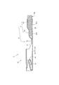
- FIG. 1 shows an explanatory view of the electric wire 1 with a crimp terminal according to the first embodiment
- FIG. 2 shows a central longitudinal sectional view in the width direction of the tip portion of the electric wire 1 with a crimp terminal
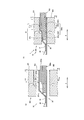
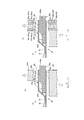
- FIG. 4 is an explanatory diagram illustrating a state of the crimping process of the electric wire 1 with the crimp terminal according to the first embodiment.
- FIG. 5 is a cross-sectional view showing the relationship between the crimping tool 300 and the cover crimping portion 31a in the crimping process of the electric wire 1 with the crimp terminal according to the first embodiment
- FIG. 6 shows the crimping method according to the first embodiment
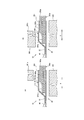
- FIG. 7 is a cross-sectional view showing a state of the crimping process of the electric wire 1 with the crimp terminal of the second embodiment
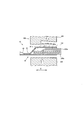
- FIG. 8 is an illustration of the crimping process of the electric wire 1 with the crimp terminal of the third embodiment. A sectional view showing the situation is shown.
- the electric wire 1 with a crimp terminal of the present embodiment is configured by connecting a covered electric wire 200 to a female crimp terminal 10 as shown in FIGS. That is, the wire tip 200 a of the covered wire 200 is crimped and connected to the crimping portion 30 of the female crimp terminal 10.
- the covered electric wire 200 to be crimped and connected to the female crimp terminal 10 is formed by covering an aluminum core wire 201 in which aluminum strands 201aa are bundled with an insulating coating 202 made of an insulating resin.
- the aluminum core wire 201 is formed by twisting an aluminum alloy wire so that the cross section becomes 0.75 mm 2 .
- the covered electric wire 200 may be not only the aluminum core wire 201 that constitutes aluminum or an aluminum alloy, but may also be a copper-based core wire that is constituted by copper or a copper alloy, and the aluminum core wire 201 has a cross section of only 0.75 mm 2. Not limited to.
- the electric wire front end portion 200a is a portion in which the covered front end portion 202a and the conductor front end portion 201a are provided in series in this order toward the front end side in the front end portion of the covered electric wire 200.
- the conductor tip 201a is a part where the insulation coating 202 on the front side of the covered electric wire 200 is peeled off and the aluminum core wire 201 is exposed.
- the covered tip portion 202 a is a tip portion of the covered electric wire 200, and is a portion on the rear side of the conductor tip portion 201 a and is a portion in which the aluminum core wire 201 is covered with the insulating coating 202.
- the female crimp terminal 10 has a box portion 20 that allows insertion tabs to be inserted into a male terminal (not shown) from the front, which is the front end side in the longitudinal direction X, to the rear, and a predetermined portion at the rear of the box portion 20.
- the crimping part 30 arranged via the length transition part 40 is integrally formed.
- the female crimp terminal 10 is composed of the box part 20 and the crimp part 30. However, if the crimp terminal has the crimp part 30, the female crimp terminal 10 described above.
- the male crimping terminal constituted by the insertion tab and the crimping part 30 to be inserted and connected to the box part 20 in this embodiment is composed only of the crimping part 30 and is crimped for bundling and connecting the aluminum core wires 201 of the plurality of covered electric wires 200. It may be a terminal.
- the longitudinal direction X is a direction that coincides with the longitudinal direction of the covered electric wire 200 that crimps and connects the crimping portion 30, and the width direction Y is the width direction of the female crimp terminal 10. It corresponds to a direction that intersects the longitudinal direction X in the plane direction.
- the side of the box part 20 with respect to the crimping part 30 is defined as the front side (front end side), and conversely, the side of the crimping part 30 with respect to the box part 20 is defined as the rear side (base end side).
- the box portion 20 is formed of an inverted hollow rectangular column body, and is bent toward the rear in the longitudinal direction X and elastic contact pieces 21 that contact an insertion tab (not shown) of the male connector to be inserted. It has.
- the box portion 20 which is a hollow quadrangular prism body is bent so that the side surface portions 23 continuously provided on both side portions in the width direction Y orthogonal to the longitudinal direction X of the bottom surface portion 22 overlap each other, and the distal end side in the longitudinal direction X It is comprised in the substantially rectangular shape seeing from.
- the crimping portion 30 is formed integrally with a wire crimping portion 31 and a sealing portion 32 in this order from the rear to the front, and in a continuous shape continuous in the entire circumferential direction.
- the wire crimping portion 31 is configured such that the covering crimping portion 31a and the conductor crimping portion 31b are continuously arranged in series in this order from the rear side to the front side, and the wire tip portion 200a can be inserted from the covering crimping portion 31a to the conductor crimping portion 31b.
- the rear side is open, and the front end side and the entire peripheral surface portion are formed in a hollow shape (cylindrical shape) that is not open, and is configured as a closed barrel type.
- the coated crimping portion 31a is a portion corresponding to the coated distal end portion 202a in the longitudinal direction X of the wire crimping portion 31 in a state where the wire distal end portion 200a is inserted into the wire crimping portion 31, and the conductor crimping portion 31b In a state where 200 a is inserted into the electric wire crimping portion 31, this is a portion corresponding to the conductor tip 201 a in the longitudinal direction X of the electric wire crimping portion 31.
- the coated crimping portion 31a and the conductor crimping portion 31b are formed in a cylindrical shape having substantially the same diameter before being crimped.
- the sealing portion 32 is deformed so as to crush the front end portion into a substantially flat plate shape rather than the wire crimping portion 31 configured in a hollow shape (cylindrical shape), and forms a female terminal 10. It is comprised by the flat shape which the material 100 superposes
- FIG. 3 is an explanatory view for explaining welding in the crimping portion 30.
- FIG. 3 (a) is an operation explanatory view showing a state where fiber laser welding is performed by the fiber laser welding apparatus Fw
- FIG. 3B is an enlarged view of part a in FIG.
- the female crimp terminal 10 described above bends the terminal base material 100 into a three-dimensional terminal shape including a box portion 20 of a hollow rectangular column and a substantially O-shaped crimp portion 30 in a rear view, and the crimp portion 30. These are welded with a laser L to form a closed crimp type female crimp terminal 10.
- the terminal base material 100 is a plate-like base material for constituting the female crimp terminal 10, and a copper alloy strip (not shown) such as brass whose surface is tin-plated (Sn plated) is planar. It is a plate material punched into a developed terminal shape, and is formed with a crimping surface and barrel constituent pieces extending from both sides in the width direction Y of the crimping surface in a portion corresponding to the crimping portion 30 before crimping. .
- the female crimp terminal 10 is formed into a cylindrical shape by rounding the terminal base material 100 in a direction having the longitudinal direction as the central axis and rounding the end portions 32a so as to face each other on the bottom side.
- the longitudinal direction welding part W1 is formed by welding a pair of opposing edge part 32a, sliding the laser irradiation apparatus Fw along the longitudinal direction X in the state which faced the opposing edge parts 32a of the terminal base material 100.
- the width direction welding location W2 is formed by welding the front part of the crimping
- FIG. 4 is an operation explanatory view showing a cross section of the crimping process of the electric wire 1 with the crimp terminal according to the first embodiment.
- FIG. 4A shows the female crimp terminal 10 with respect to the electric wire tip 200a.
- FIG. 4B is a longitudinal cross-sectional view showing a state immediately after the female crimp terminal 10 is crimped to the electric wire tip portion 200a.
- FIG. 4C is an enlarged view of part a in FIG.
- tip part 200a is inserted in the electric wire crimping part 31 in the crimping
- FIG. 4 (a) the sheath tip 202a of the wire tip portion 200a is inserted into the sheath crimp portion 31a, and the conductor tip portion of the wire tip portion 200a is inserted into the conductor crimp portion 31b. 201a is inserted.
- the wire crimping portion 31 is pressed by the crimping tool 300 constituted by the crimper 301 and the anvil 302 that are engaged with each other, and the wire crimping portion 31 is crimped to the wire tip portion 200a.
- the crimper 301 and the anvil 302 are arranged to face each other with the crimping portion 30 interposed therebetween.
- the crimping portion 30 is sandwiched between the crimper 301 and the anvil 302 from both sides, thereby crimping the wire crimping portion 31 to the wire tip 200a as shown in FIG.
- the female crimp terminal 10 can be crimped and connected to the wire tip portion 200 a of the covered wire 200.
- FIG. 5 is a cross-sectional view showing the relationship between the crimping tool 300 and the cover crimping portion 31a in the crimping process of the electric wire 1 with the crimp terminal according to the first embodiment.
- FIG. 5 (a) is the same as FIG. 4 (a).
- FIG. 5B is a cross-sectional view taken along the line BB of FIG. 4A
- FIG. 5C is a cross-sectional view taken along the line AA of FIG. 4B.
- FIG. 5 is a cross-sectional view taken along the line AA of FIG. 4B.
- FIG. 5 (d) is a cross-sectional view taken along line BB of FIG. 4 (b).
- FIGS. 5A, 5B, 5C, and 5D are cross-sectional views in which the longitudinal direction of the coated crimp portion 31a is a normal line.
- FIG. 5E is a graph schematically showing changes in the widths WD1 and WD2 of the portion where the cover crimping portion 31a in the crimper 301 is crimped.
- the crimping tool 300 is configured as shown in FIGS. 5 (a) and 5 (b).
- a concave portion 311 that engages with the anvil 302 is formed at a position facing the anvil 302 in the crimper 301, and the concave portion 311 communicates with the bottom portion 311a that defines the shape of the coated crimp portion 31a after crimping, and the bottom portion 311a. It is comprised with the communication part 311b.
- the width WD2 of the communication portion 311b when viewed in a cross section with the longitudinal direction of the coated crimp portion 31a as a normal line increases from the boundary between the bottom 311a and the communication portion 311b toward the opening 312 of the recess 311.
- the width WD2 at a specific depth of the communication portion 311b at the first position (here, the position of the tip end portion PO1) along the longitudinal direction of the covering crimping portion 31a is shown in FIGS.
- the width WD2 at a specific depth of the communication portion 311b at the second position here, the position of the base end side end portion PO2 along the longitudinal direction of the covering crimping portion 31a.
- the width WD2 is desirably increased from the first position toward the second position along the longitudinal direction of the covering crimping portion 31a.
- the width WD1 of the bottom 311a is constant regardless of the position in the longitudinal direction of the coated crimping portion 31a.
- the width WD1 of the bottom portion 311a may be different from each other at the position of the distal end side end portion PO2 and the position of the proximal end side end portion PO1 along the longitudinal direction of the covering crimping portion 31a.
- the crimping of the proximal end PO1 can be started before the crimping of the distal end PO2. Further, the crimping of the proximal end part PO1 and the crimping of the distal end part PO2 can be performed in the same process.
- the proximal end PO1 is in contact with the wall surface of the communication portion 311b of the crimper 301 as shown in FIG. Then, the crimping of the proximal end PO1 starts.
- the cover crimping portion 31a of the distal end side PO2 is still in contact with the crimper 301. In other words, the crimping of the distal end side end PO2 is not started.
- the crimping of the distal end side end PO2 is started after the crimping of the proximal end PO1 is started.
- the proximal end portion PO1 With time elapses.
- the crimping starts in sequence from the tip toward the distal end side end PO2.
- the crimping of the distal end side end portion PO2 starts after the proximal end side end portion PO1 starts to be crimped, and then sequentially crimps toward the distal end side of the conductor crimping portion 31b. That is, in the crimping step, the crimping of the conductor crimping portion 31b is started after the crimping of the covering crimping portion 31a is started.
- the distal end side PO2 and the proximal side Each of the end portions PO1 is crimped by the wall surface of the bottom portion 311a, and the shape is defined by the bottom portion 311a.
- the width WD1 of the bottom 311a is constant regardless of the position in the longitudinal direction of the coated crimping part 31a, the width of the coated crimping part 31a becomes uniform along the longitudinal direction of the coated crimped part 31a.
- the coating crimping portion 31a is deformed and the sheath inserted into the coating crimping portion 31a. Pressure is applied to the tip 202a. The coating tip 202a is elastically deformed by this pressure. Since the coated crimping portion 31a is a closed barrel type coated crimping portion 31a, the internal pressure of the coated crimping portion 31a is increased by the repulsive force of the coated distal end portion 202a.
- the coated distal end portion 202a is moved to the proximal end side (upper right direction in FIG. 6A), so that the conductor distal end portion 201a is coated. It is exposed from the crimping part 31a and stable conductivity cannot be obtained.
- the crimping of the proximal end side end PO1 of the coated crimping portion 31a is started before the crimping of the distal end side end PO2 of the coated crimping portion 31a, and the conductor The crimping portion 31b is sequentially crimped.
- the female crimp terminal 10 and the covered electric wire 200 after the completion of the crimping are in a state as shown in FIG.
- the covering distal end portion 202a existing inside the covering crimping portion 31a in the proximal end portion PO1 is elastically deformed by pressing, and the repulsive force causes the proximal end portion PO1.
- the internal pressure of the coated crimping portion 31a at the end increases, and the coated distal end portion 202a is fixed to the coated crimped portion 31a at the proximal end PO1.
- the covered electric wire 200 does not move toward the base end side end PO1 (to the right in FIG. 6D) by pressing.
- the distal end of the covered electric wire 200 with respect to the distal end side of the proximal end PO1 is compared with the distal end. Since a force toward the portion PO2 (a force toward the left in FIG. 6D) can be applied, the effect of suppressing the exposure of the conductor tip 201a can be enhanced.
- the conductor crimping part 31b may be crimped in the same process or another process subsequent to the crimping of the coated crimping part 31a, or the conductor crimping part 31b is crimped before the coated crimping part 31a.
- the above-described effects can be achieved even if the pressure is pressed. Below, the crimping
- FIG. 7 is an operation explanatory view showing a cross section of the crimping process of the electric wire 1 with crimp terminal of the second embodiment. Specifically, FIG. 7A shows the base end side PO1 of the coated crimp part 31a. FIG. 7B is a longitudinal sectional view showing a state immediately before crimping the distal end side end PO2 of the coated crimping portion 31a.
- the crimper 301 is divided into a crimper 301a and a crimper 301b, and the crimping of the proximal end PO1 and the distal end PO2 are performed. Is performed in a separate process.
- the crimping portion 30 is sandwiched from both sides by the crimper 301a and the anvil 302, so that the coated crimping portion 31a near the proximal end PO1 is made into the coated distal end portion 202a. Crimp against it. At this time, the tip end portion PO2 is not crimped by the crimper 301a.
- the crimping part 30 is sandwiched from both sides by the crimper 301b and the anvil 302, so that the covering crimping part 31a near the distal end side end PO2 is formed.
- the conductor crimping part 31b is crimped to the conductor tip part 201a while being crimped to the covering tip part 202a.
- the cover crimping portion 31a can be crimped again to the proximal end PO1.
- the female crimp terminal 10 can be crimped and connected to the wire tip portion 200a.
- the crimper 301 is separated into the crimper 301a and the crimper 301b, and the crimping of the proximal end PO1 and the crimping of the distal end PO2 are performed in separate steps, that is, By crimping the covering crimping portion 31a in a plurality of times, the crimping of the proximal end portion PO1 can be started before the crimping of the distal end portion PO2.
- the cross-sectional shape of the portion that presses the proximal end portion PO1 in the crimper 301a with the longitudinal direction of the coated crimping portion 31a as the normal line and the cross-sectional shape of the portion that presses the distal end portion PO2 in the crimper 301b are These may be the same or different from each other as shown in FIGS. 5 (a) and 5 (b).
- the crimper 301 can be configured such that the portion of the crimper 301 that presses the conductor tip 201a is separated from the portion of the crimper 301 that presses the wire tip 200a. Thereby, the crimping
- FIG. 8 is an operation explanatory view showing a state of the crimping process of the electric wire 1 with the crimp terminal of the third embodiment by a cross section. Specifically, the state immediately before the female crimp terminal 10 is crimped to the electric wire tip portion 200a.
- FIG. 8 is an operation explanatory view showing a state of the crimping process of the electric wire 1 with the crimp terminal of the third embodiment by a cross section. Specifically, the state immediately before the female crimp terminal 10 is crimped to the electric wire tip portion 200a.
- a portion (bottom portion 311a) of the crimper 301 that presses the coated crimping portion 31a is provided with an inclination in the direction toward the anvil 302 (lower side in FIG. 8).
- the portion of the crimper 301 that presses the coated crimping portion 31a extends from the portion that presses the distal end side end portion PO2 to the portion that presses the proximal end side end portion PO1 toward the anvil 302 (lower side in FIG. 8). Protruding.
- the crimping of the proximal end PO1 is more than the crimping of the distal end PO2. Can start first.
- connection structure of the present invention corresponds to the electric wire 1 with the crimp terminal of the embodiment
- the crimp terminal corresponds to the female crimp terminal 10
- the conductor corresponds to the aluminum core wire 201
- the crimping device corresponds to the crimping tool 300
- the first type corresponds to the crimpers 301, 301a, 301b
- the second type corresponds to anvil 302
- the present invention is not limited to the configuration of the above-described embodiment, but can be applied based on the technical idea shown in the claims, and many embodiments can be obtained.
- the configuration, the manufacturing method, and the configuration of the crimping tool 200 of the electric wire 1 with the crimp terminal of the first, second, and third embodiments are not limited to the above-described configuration and the manufacturing method.
- a concave portion having a width WD2 as shown in FIG. 5 (e) is not provided on the crimper 301 side so that the crimping of the proximal end PO1 starts before the distal end PO2. You may provide in the anvil 302 side.
- FIG. 9A and FIG. 9B are cross-sectional views showing a state before the crimping process in another embodiment.
- the coated crimping portion 31a can be strongly crimped more locally than the portion other than the convex portion 300z, so that the conductor tip 201a can be prevented from being displaced from the conductor crimping portion 31b, and the stop Aqueous property can be improved.
- the crimper 301a and the anvil 302 are not limited to the configuration provided with the convex portion 300z as described above, and may have a structure in which the crimper 301a and the anvil 302 are further divided.
- the crimper 301a can be constituted by a crimper 301c having a convex part 300z and a crimper 301d constituted by a part other than the convex part 300z. These crimpers 301c and 301d are alternately arranged in parallel along the longitudinal direction X.
- the anvil 302 can also be composed of an anvil 302a having a convex portion 300z and an anvil 302b having a portion other than the convex portion 300z. At least one of the crimpers 301c and 301d and the anvils 302a and 302b may be configured to be interlocked with each other, or may be configured to move independently.
- the crimping process is not limited to starting the crimping of the conductor crimping portion 31b after the crimping of the covering crimping portion 31a is started, but the crimping of the coating crimping portion 31a, the crimping of the conductor crimping portion 31b, and the covering You may perform the crimping
- the coated crimping part 31b By performing the crimping process as described above, even if the crimping of the conductor crimping part 31b affects the crimping state of the coated crimping part 31a performed before the crimping of the conductor crimping part 31b, the coated crimping part again.
- the pressure bonding of 31a By performing the pressure bonding of 31a, it is possible to ensure water-stopping and pressure-bonding strength.
- at least one of the crimping of the covering crimping portion 31a performed before and after the crimping of the conductor crimping portion 31b may be performed using the crimpers 301c and 301d and the anvils 302a and 302b.
- the proximal end PO1 and the distal end PO2 may be crimped simultaneously, or the proximal end The crimping of the tip end side end PO2 may be started before the crimping of the side end PO1.
- the cover crimping portion 31a and the conductor crimping portion 31b are not limited to the wire crimping portion 31 formed in a cylindrical shape having substantially the same diameter in the state before the crimping, but are also illustrated in FIGS. As shown in FIG. 10 (b), it may be a wire crimping portion 31z in which the coated crimping portion 31a and the conductor crimping portion 31b are formed in a stepped shape.
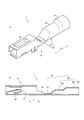
- 10A shows a perspective view of the female crimp terminal 10 having the stepped wire crimping portion 31z
- FIG. 10B shows a cross section of the female crimp terminal 10 having the stepped wire crimping portion 31z. The figure is shown.
- the diameter of the coated crimping portion 31a is substantially the same as or slightly larger than the diameter of the insulating coating 202, and the diameter of the conductor crimping portion 31b is substantially equal to or slightly smaller than the diameter of the aluminum core wire 201.
- the wire crimping portion 31z is formed in a step shape.
- the gap between the conductor crimping portion 31b and the aluminum core wire 201 before crimping can be reduced as compared with the case where the wire crimping portion 31 is not formed in a stepped shape. Accordingly, it is possible to further prevent the conductor tip portion 201a from being displaced from the conductor crimping portion 31b and the aluminum core wire 201 from jumping out of the wire crimping portion 31.
- the diameter reduction ratio of the conductor crimping portion 31b when crimping to the aluminum core wire 201 is reduced, and the material of the conductor crimping portion 31b generated during crimping is reduced. Prevent it from appearing as surplus. Therefore, a crimped state in which the conductor crimping portion 31b and the aluminum core wire 201 are in close contact with each other can be obtained.
- SYMBOLS 1 Electric wire 10 with a crimp terminal ... Female crimp terminal 30 ... Crimp part 31a ... Cover crimp part 31b ... Conductor crimp part 200 ... Cover electric wire 200a ... Electric wire tip 201 ... Aluminum core wire 201a ... Conductor tip part 202 ... Insulation coating 202a ... covering tip 300 ... crimping tool 300z ... projections 301, 301a to 301d ... crimpers 302, 302a, 302b ... anvil 311 ... concave 311a ... bottom 311b ... communication part WD2 ... width at a specific depth of the communication part
Landscapes
- Engineering & Computer Science (AREA)
- Manufacturing & Machinery (AREA)
- Connections Effected By Soldering, Adhesion, Or Permanent Deformation (AREA)
- Manufacturing Of Electrical Connectors (AREA)
Abstract
【課題】接続構造体の安定した導電性を得ること。【解決手段】導体(201)を絶縁被覆(202)で被覆した被覆電線(200)における電線先端部(200a)の圧着接続を許容する圧着部(30)を備えた圧着端子(10)における圧着部(30)によって、被覆電線(200)と圧着端子(10)とを圧着接続する接続構造体(1)の製造方法において、圧着部(30)を、断面中空形状で構成するとともに、長手方向(X)の先端側から基端側へこの順に、導体先端部(201a)を圧着する導体圧着部(31b)と、被覆先端部(202a)を圧着する被覆圧着部(31a)とを配設し、被覆圧着部(31a)を、断面中空形状の圧着部で構成し、被覆先端部(202a)に被覆圧着部(31a)を圧着接続する際に、被覆圧着部(31a)の圧着を導体圧着部(31b)の圧着よりも先に開始する。
Description
この発明は、例えば自動車用ワイヤーハーネスのコネクタ等に装着されるような接続構造体の製造方法、接続構造体、及び圧着装置に関する。
自動車等に装備された電装機器は、被覆電線を束ねたワイヤーハーネスを介して、別の電装機器や電源装置と接続して電気回路を構成している。この際、ワイヤーハーネスと電装機器や電源装置とは、それぞれに装着したコネクタ同士で接続されている。上述したコネクタには、圧着端子を被覆電線に対して圧着接続した接続構造体が装着されている。
昨今の電装品の多機能化、高性能化に伴って電気回路はますます複雑化しており、各圧着端子と被覆電線との圧着接続部での導通性の確実性がより求められている。そのため、これまでのように、オープンバレル型の圧着端子の場合、過酷な使用環境下において圧着部は露出しているため、圧着接続部分における圧着部表面や導体表面が腐食し、導電性が低下するおそれがあった。
このような問題に対して、例えば、特許文献1の段落[0005]に記載されているクローズドバレル型の圧着部を備えた圧着端子を用いることにより、圧着接続部分における圧着部表面や導体表面に生じる腐食を防止することが想定できる。
クローズドバレル型の圧着端子としては、例えば下記特許文献2に開示されたものがある。特許文献2の圧着端子は、特許文献2の図10~図15に開示されているように、長手方向の一方に、他端を閉じた円筒状の圧着部を有している。この円筒状の圧着部に、被覆電線の先端部分を挿入して圧着することで、圧着端子と被覆電線の導体とを確実に導通させ、また、圧着接続部分における圧着部表面や導体表面に生じる腐食を防止することができると考えられる。
しかし、実際にはクローズドバレル型の圧着部を備えた圧着端子を用いるだけでは、実用に耐えるだけの腐食を抑えることはできず、止水材やモールド樹脂などの樹脂材料を用いて圧着部を封止する必要があり、工数やコストも高くなっていた。
また、上述したようなコネクタは、様々な環境の下で使用されているため、雰囲気温度の変化による結露などによって意図しない水分が被覆電線の表面に付着することがあった。
また、上述したようなコネクタは、様々な環境の下で使用されているため、雰囲気温度の変化による結露などによって意図しない水分が被覆電線の表面に付着することがあった。
このような圧着端子において、挿入孔に挿入した状態で圧着端子を圧着し、圧着後に導体先端部が外部に露出しないように構成しているが、被覆圧着部の基端部、すなわち、挿入孔の基端側の口縁部は、基端方向に向けて突状となる自由端であるため、圧着端子を圧着する際に、前記被覆先端部が挿入孔の基端側へ移動することがあった。その結果、圧着後に前記導体先端部が外部に露出し、前記導体先端部の表面が腐食し、安定した導電性が得られないおそれがあった。
この発明は、安定した導電性を得ることができる接続構造体の製造方法、接続構造体、及び圧着装置を提供することを目的とする。
この発明は、導体を絶縁被覆で被覆した被覆電線における電線先端部の圧着接続を許容する圧着部を備えた圧着端子における前記圧着部によって前記被覆電線と前記圧着端子とを圧着接続する接続構造体の製造方法であって、前記電線先端部は、前記被覆電線における先端側の前記絶縁被覆を剥がして前記導体を露出させた導体先端部と、前記絶縁被覆の先端部分に有する被覆先端部とで構成され、前記圧着部を、断面中空形状の圧着部で構成するとともに、前記導体先端部を圧着する導体圧着部と、前記被覆先端部を圧着する被覆圧着部とを配置して構成し、前記電線先端部に前記圧着部を圧着接続する電線圧着工程において、前記電線先端部を前記圧着部の内部に配置し、前記被覆圧着部の圧着を、前記導体圧着部の圧着よりも先に開始することを特徴とする。
上記圧着端子は、一対構成した端子組の他方の端子の接続部との接続を許容する接続部を有する接続端子、あるいは圧着部のみで構成する端子であることを含む。
上記圧着端子は、一対構成した端子組の他方の端子の接続部との接続を許容する接続部を有する接続端子、あるいは圧着部のみで構成する端子であることを含む。
この発明によれば、安定した導電性を得ることができる。
詳述すると、被覆圧着部の圧着を、導体圧着部の圧着よりも先に開始することにより、被覆圧着部の内部に存在する被覆先端部が押圧により弾性変形し、その反発力により被覆圧着部の内圧が高まり、被覆先端部が被覆圧着部に固定される。これにより、導体先端部は、押圧により被覆圧着部の方へ移動しにくくなる。その結果、導体先端部が被覆圧着部から露出することを抑止することができ、安定した導電性を得ることができる。
詳述すると、被覆圧着部の圧着を、導体圧着部の圧着よりも先に開始することにより、被覆圧着部の内部に存在する被覆先端部が押圧により弾性変形し、その反発力により被覆圧着部の内圧が高まり、被覆先端部が被覆圧着部に固定される。これにより、導体先端部は、押圧により被覆圧着部の方へ移動しにくくなる。その結果、導体先端部が被覆圧着部から露出することを抑止することができ、安定した導電性を得ることができる。
この発明の態様として、前記電線圧着工程において、前記導体圧着部の圧着と前記被覆圧着部の圧着とを同一工程にて行うことができる。
この発明により、導体圧着部の圧着と被覆圧着部の圧着とを別工程にて行う必要がなくなり、製造工程の簡略化を図ることができる。
この発明により、導体圧着部の圧着と被覆圧着部の圧着とを別工程にて行う必要がなくなり、製造工程の簡略化を図ることができる。
またこの発明の態様として、前記電線圧着工程において、前記圧着部の基端側端部の圧着を、前記圧着部の先端側端部の圧着よりも先に開始することができる。
好ましくは、基端側端部から先端側端部に向かって順に圧着を開始するとよい。
好ましくは、基端側端部から先端側端部に向かって順に圧着を開始するとよい。
この発明により、被覆電線における、基端側端部よりも先端側の部分に対し、先端側へ向かう力を加えることができるので、導体先端部の露出を抑止する効果を高めることができる。
従って、導体先端部が被覆圧着部から露出することを抑止することができ、安定した導電性を得ることができる。
従って、導体先端部が被覆圧着部から露出することを抑止することができ、安定した導電性を得ることができる。
またこの発明の態様として、前記電線圧着工程において、前記導体圧着部の圧着と前記被覆圧着部の圧着とを別工程にて行うことができる。
この発明により、被覆圧着部の圧着を、導体圧着部の圧着よりも先に開始することが容易になる。
この発明により、被覆圧着部の圧着を、導体圧着部の圧着よりも先に開始することが容易になる。
またこの発明は、上記接続構造体の製造方法により製造した接続構造体であることを特徴とする。
この発明によれば、安定した導電性を得ることができる。
この発明によれば、安定した導電性を得ることができる。
この発明の態様として、前記圧着端子が銅又は銅合金製であるとともに、前記被覆電線の前記導体がアルミ又はアルミ合金製であることができる。
この発明により、銅線による導体部分を有する被覆電線に比べて軽量化できるとともに、上述した封止部によって確実な止水性が得られるので、いわゆる異種金属腐食(以下において電食という)を防止することができる。
この発明により、銅線による導体部分を有する被覆電線に比べて軽量化できるとともに、上述した封止部によって確実な止水性が得られるので、いわゆる異種金属腐食(以下において電食という)を防止することができる。
詳しくは、被覆電線の導体に従来用いられていた銅系材料をアルミニウムあるいはアルミニウム合金などのアルミ系材料に置き換え、そのアルミ系材料製の導体を圧着端子に圧着した場合においては、端子材料の錫めっき、金めっき、銅合金等の貴な金属との接触により、卑な金属であるアルミ系材料が腐食される現象、すなわち電食が問題となる。
なお、電食とは、貴な金属と卑な金属とが接触している部位に水分が付着すると、腐食電流が生じ、卑な金属が腐食、溶解、消失等する現象である。この現象により、圧着端子の圧着部に圧着されたアルミ系材料製の導体が腐食、溶解、消失し、やがては電気抵抗が上昇する。その結果、十分な導電機能を果たせなくなるという問題があった。
しかしながら、上述した導体を、圧着部内の所定位置に挿入したまま圧着接続することで、銅系材料による導体を有する被覆電線に比べて軽量化を図りながら、いわゆる電食を防止することができる。
この結果、圧着端子と、被覆電線の導体を構成する金属種によらず、安定した導電性を確保した接続状態を構成することができる。
この結果、圧着端子と、被覆電線の導体を構成する金属種によらず、安定した導電性を確保した接続状態を構成することができる。
ここで、前記圧着部は、例えば、銅、銅合金等の銅系材料で構成することができる。また、導体は、例えば、アルミニウム製素線あるいはアルミニウム合金製素線等で構成することができる。
またこの発明は、導体を絶縁被覆で被覆した被覆電線における先端部である電線先端部を圧着端子の内部に配置した状態で、前記電線先端部を前記圧着端子に圧着接続する圧着装置であって、前記電線先端部は、前記被覆電線における先端側の前記絶縁被覆を剥がして前記導体を露出させた導体先端部と、前記絶縁被覆の先端部分に有する被覆先端部とで構成され、前記被覆先端部の圧着が前記導体先端部の圧着よりも先に開始するように、前記圧着端子を圧着する圧着部材を備えたことを特徴とする。
この発明により、安定した導電性を得ることができる。
この発明により、安定した導電性を得ることができる。
この発明の態様として、前記圧着部材を第1の型と、前記第1の型と係合する第2の型とで構成し、前記第1の型における前記第2の型と対向する位置に凹部を形成し、前記凹部を、圧着後の前記圧着端子の形状を規定する底部と、前記底部と外部とを連通し、前記圧着端子の長手方向を法線とする断面で見た場合の幅が前記底部との境界部から前記凹部の開口部に向かって増加する連通部とで構成し、前記長手方向に沿った第1の位置における前記連通部の特定の深さでの前記幅を、前記長手方向に沿った前記第1の位置とは異なる第2の位置における前記連通部の特定の深さでの前記幅よりも小さくすることができる。
この発明により、第1の位置における連通部の特定の深さでの幅は、第2の位置における連通部の特定の深さでの幅よりも小さいので、被覆圧着部を押圧する圧着端子の部分が連通部の第1の位置の壁面と接触し、被覆圧着部の圧着が開始するタイミングでは、導体圧着部を押圧する圧着端子の部分は連通部の第2の位置の壁面と接触せず、導体圧着部の圧着は開始しないようにすることができる。その結果、被覆圧着部の圧着を導体圧着部の圧着よりも先に開始することができる。
前記第1の型における、前記被覆先端部を圧着する部分に、前記第2の型の方向へ突出する第1凸部を備えるとともに、前記第2の型における、前記被覆先端部を圧着する部分に、前記第1凸部の方向へ突出する第2凸部を備え、前記第1凸部と第2凸部とを、対向する位置に配設することができる。
この発明により、被覆圧着部における、第1凸部と第2凸部とに圧着される部分は、第1凸部と第2凸部とに圧着されない部分よりも局部的に大きな荷重で圧着されるため、電線先端部が電線圧着部から飛び出ることをより防止することができるとともに、止水性をより向上させることができる。
好ましくは、被覆圧着部における、導体圧着部との境界付近に第1凸部と第2凸部とを備えることが望ましい。
これにより、導体先端部が導体圧着部からずれることを防止することはもちろん、被覆圧着部の内部に導体が浸入することを防止して、侵入した導体によって絶縁被覆が傷付くことを防止することができる。
なお、第1の型と第2の型とは、上述のような第1凸部と第2凸部とを備えた構成だけに限らず、第1の型を、第1凸部の部分と、第1凸部以外の部分とを分割して構成したものを組み立てた第1の型であってもよい。これら第1凸部の部分と第1以外の部分とは、互いに連動する構成であってもよく、それぞれが単独で移動する構成であってもよい。第2の型においても、第1の型と同様に、分割構造であってもよい。
この発明によれば、安定した導電性を得ることができる接続構造体の製造方法、接続構造体、及び圧着装置を提供することができる。
この発明の一実施形態を以下図面に基づいて詳述する。
なお、図1は第1実施形態の圧着端子付き電線1の説明図を示し、図2は圧着端子付き電線1の先端部分の幅方向中央縦断面図を示し、図3は圧着部30における溶接について説明する説明図を示し、図4は、第1実施形態の圧着端子付き電線1の圧着工程の様子を示す説明図を示している。
また、図5は第1実施形態の圧着端子付き電線1の圧着工程における圧着工具300と被覆圧着部31aとの関係を示した断面図を示し、図6は第1実施形態の圧着方法が奏する作用効果の説明図を示し、図7は第2実施形態の圧着端子付き電線1の圧着工程の様子を示す断面図を示し、図8は第3実施形態の圧着端子付き電線1の圧着工程の様子を示す断面図を示している。
(第1実施形態)
本実施形態の圧着端子付き電線1は、図1(a)及び図2に示すように、被覆電線200を雌型圧着端子10に接続して構成している。つまり、被覆電線200における電線先端部200aを、雌型圧着端子10の圧着部30に圧着接続している。
本実施形態の圧着端子付き電線1は、図1(a)及び図2に示すように、被覆電線200を雌型圧着端子10に接続して構成している。つまり、被覆電線200における電線先端部200aを、雌型圧着端子10の圧着部30に圧着接続している。
雌型圧着端子10に圧着接続する被覆電線200は、アルミニウム素線201aaを束ねたアルミニウム芯線201を、絶縁樹脂で構成する絶縁被覆202で被覆して構成している。詳しくは、アルミニウム芯線201は、断面が0.75mm2となるように、アルミニウム合金線を撚って構成している。
なお、被覆電線200は、アルミニウムやアルミニウム合金を構成するアルミニウム芯線201だけでなく、銅や銅合金で構成する銅系芯線であってもよく、アルミニウム芯線201の断面を0.75mm2とするだけに限らない。
なお、被覆電線200は、アルミニウムやアルミニウム合金を構成するアルミニウム芯線201だけでなく、銅や銅合金で構成する銅系芯線であってもよく、アルミニウム芯線201の断面を0.75mm2とするだけに限らない。
電線先端部200aは、被覆電線200の先端部分において、被覆先端部202aと導体先端部201aとを先端側へ向けてこの順に直列に備えた部分である。
導体先端部201aは、被覆電線200の前方側の絶縁被覆202を剥がしてアルミニウム芯線201を露出させた部分である。被覆先端部202aは、被覆電線200の先端部分であるが、導体先端部201aよりも後方側部分であって、アルミニウム芯線201を絶縁被覆202で被覆した部分である。
導体先端部201aは、被覆電線200の前方側の絶縁被覆202を剥がしてアルミニウム芯線201を露出させた部分である。被覆先端部202aは、被覆電線200の先端部分であるが、導体先端部201aよりも後方側部分であって、アルミニウム芯線201を絶縁被覆202で被覆した部分である。
以下において、雌型圧着端子10について詳述する。
雌型圧着端子10は、長手方向Xの先端側である前方から後方に向かって、図示省略する雄型端子における挿入タブの挿入を許容するボックス部20と、ボックス部20の後方で、所定の長さのトランジション部40を介して配置された圧着部30とを一体に構成している。
雌型圧着端子10は、長手方向Xの先端側である前方から後方に向かって、図示省略する雄型端子における挿入タブの挿入を許容するボックス部20と、ボックス部20の後方で、所定の長さのトランジション部40を介して配置された圧着部30とを一体に構成している。
なお、本実施形態では、上述したように、ボックス部20と圧着部30で構成する雌型圧着端子10で構成したが、圧着部30を有する圧着端子であれば、上述の雌型圧着端子10におけるボックス部20に挿入接続する挿入タブと圧着部30とで構成する雄型圧着端子でも、圧着部30のみで構成し、複数本の被覆電線200のアルミニウム芯線201を束ねて接続するための圧着端子であってもよい。
また、長手方向Xとは、図1に示すように、圧着部30を圧着して接続する被覆電線200の長手方向と一致する方向であり、幅方向Yは雌型圧着端子10の幅方向に相当し、長手方向Xに対して平面方向において交差する方向である。また、圧着部30に対するボックス部20の側を前方(先端側)とし、逆に、ボックス部20に対する圧着部30の側を後方(基端側)としている。
ボックス部20は、倒位の中空四角柱体で構成され、内部に、長手方向Xの後方に向かって折り曲げられ、挿入される雄型コネクタの挿入タブ(図示省略)に接触する弾性接触片21を備えている。
ボックス部20は、倒位の中空四角柱体で構成され、内部に、長手方向Xの後方に向かって折り曲げられ、挿入される雄型コネクタの挿入タブ(図示省略)に接触する弾性接触片21を備えている。
また、中空四角柱体であるボックス部20は、底面部22の長手方向Xと直交する幅方向Yの両側部に連設された側面部23を重なり合うように折り曲げて、長手方向Xの先端側から見て略矩形状に構成している。
圧着部30は、電線圧着部31と封止部32とを後方から前方側へこの順に配設するとともに、周方向全体において連続する連続形状で一体に形成している。
圧着部30は、電線圧着部31と封止部32とを後方から前方側へこの順に配設するとともに、周方向全体において連続する連続形状で一体に形成している。
電線圧着部31は、被覆圧着部31a及び導体圧着部31bを、後方から前方側へこの順に連続して直列に配設し、被覆圧着部31aから導体圧着部31bにかけて電線先端部200aを挿入可能に後方側のみが開口するとともに、先端側及び周面部全体が開口していない中空形状(筒状)で構成し、クローズドバレル型で構成している。
被覆圧着部31aは、電線先端部200aを電線圧着部31に挿入した状態において、電線圧着部31の長手方向Xにおける被覆先端部202aに相当する部分であり、導体圧着部31bは、電線先端部200aを電線圧着部31に挿入した状態において、電線圧着部31の長手方向Xにおける導体先端部201aに相当する部分である。
なお、被覆圧着部31a及び導体圧着部31bは、圧着前の状態においては互いに略同じ径をした筒状に形成している。
なお、被覆圧着部31a及び導体圧着部31bは、圧着前の状態においては互いに略同じ径をした筒状に形成している。
封止部32は、中空形状(筒状)で構成した電線圧着部31よりも前方端部を略平板状に押し潰すように変形させて、雌型圧着端子10を構成する板状の端子基材100が重合する偏平形状で構成している。
続いて、上述した雌型圧着端子10の製造方法について図3を用いて説明する。
図3は圧着部30における溶接について説明する説明図を示し、詳しくは、図3(a)はファイバーレーザ溶接装置Fwでファイバーレーザ溶接を行っている様子を示す作用説明図であり、図3(b)は図3(a)のa部拡大図である。
図3は圧着部30における溶接について説明する説明図を示し、詳しくは、図3(a)はファイバーレーザ溶接装置Fwでファイバーレーザ溶接を行っている様子を示す作用説明図であり、図3(b)は図3(a)のa部拡大図である。
上述した雌型圧着端子10は、端子基材100を、中空四角柱体のボックス部20と後方視略O型の圧着部30とからなる立体的な端子形状に曲げ加工するとともに、圧着部30をレーザーLにより溶接してクローズドバレル形式の雌型圧着端子10で構成している。
なお、端子基材100は、雌型圧着端子10を構成するために板状の基材であり、表面が錫メッキ(Snメッキ)された黄銅等の銅合金条(図示せず)を、平面展開した端子形状に打ち抜いた板材であり、圧着前の圧着部30に相当する部分に、圧着面、及び該圧着面の幅方向Yの両側から延出したバレル構成片を備えて形成している。
詳しくは、雌型圧着端子10は、端子基材100を、長手方向を中心軸とする方向に丸めて端部32a同士が底面側で突き合わさるようにして丸めて円筒状を構成する。そして、端子基材100の対向端部32a同士を突き合わせた状態でレーザー照射装置Fwを長手方向Xに沿ってスライドさせながら一対の対向端部32a同士を溶接することで長手方向溶接部W1を形成する。
その後、レーザー照射装置Fwを圧着部30の前方側で長手方向Xに沿ってスライドさせながら圧着部30の前方部分を溶接することで幅方向溶接箇所W2を形成する。
その後、レーザー照射装置Fwを圧着部30の前方側で長手方向Xに沿ってスライドさせながら圧着部30の前方部分を溶接することで幅方向溶接箇所W2を形成する。
続いて、上述した雌型圧着端子10を、電線先端部200aに圧着接続する圧着工程について図4(a),(b),(c)を用いて説明する。
図4は第1実施形態の圧着端子付き電線1の圧着工程の様子を断面により示した作用説明図であり、詳しくは、図4(a)は電線先端部200aに対して雌型圧着端子10を圧着する直前の状態を示す縦断面図であり、図4(b)は電線先端部200aに対して雌型圧着端子10を圧着した直後の状態を示す縦断面図である。図4(c)は図4(b)のa部拡大図である。
図4は第1実施形態の圧着端子付き電線1の圧着工程の様子を断面により示した作用説明図であり、詳しくは、図4(a)は電線先端部200aに対して雌型圧着端子10を圧着する直前の状態を示す縦断面図であり、図4(b)は電線先端部200aに対して雌型圧着端子10を圧着した直後の状態を示す縦断面図である。図4(c)は図4(b)のa部拡大図である。
まず、図4(a)に示すように、圧着部30における電線圧着部31に電線先端部200aを挿入する。このとき、図4(a)に示すように、被覆圧着部31aの内部に電線先端部200aの被覆先端部202aが挿入されるとともに、導体圧着部31bの内部に電線先端部200aの導体先端部201aが挿入される。
この状態で、互いに係合するクリンパ301とアンビル302とで構成された圧着工具300により電線圧着部31を押圧し、電線先端部200aに対して電線圧着部31を圧着する。
この状態で、互いに係合するクリンパ301とアンビル302とで構成された圧着工具300により電線圧着部31を押圧し、電線先端部200aに対して電線圧着部31を圧着する。
その際、図4(a)に示すように、クリンパ301とアンビル302を、圧着部30を隔てて互いに対向配置させる。
この状態でクリンパ301とアンビル302により圧着部30を両側から挟み込むことで、図4(b)に示すように、電線圧着部31を電線先端部200aに圧着する。
これにより、図2に示すように、被覆電線200の電線先端部200aに対して雌型圧着端子10を圧着接続することができる。
この状態でクリンパ301とアンビル302により圧着部30を両側から挟み込むことで、図4(b)に示すように、電線圧着部31を電線先端部200aに圧着する。
これにより、図2に示すように、被覆電線200の電線先端部200aに対して雌型圧着端子10を圧着接続することができる。
続いて、上述した圧着工程に使用される圧着工具300の詳細な構成、及び圧着工程における被覆圧着部31aの挙動について詳細に説明する。
図5は第1実施形態の圧着端子付き電線1の圧着工程における圧着工具300と被覆圧着部31aとの関係を示した断面図であり、詳しくは、図5(a)は図4(a)のA-A線断面図であり、図5(b)は図4(a)のB-B線断面図であり、図5(c)は図4(b)のA-A線断面図であり、図5(d)は図4(b)のB-B線断面図である。図5(a)、(b)、(c)、及び(d)はいずれも、被覆圧着部31aの長手方向を法線とする断面図である。図5(e)はクリンパ301おける被覆圧着部31aを圧着する部分の幅WD1及びWD2の変化を模式的に示すグラフである。
図5は第1実施形態の圧着端子付き電線1の圧着工程における圧着工具300と被覆圧着部31aとの関係を示した断面図であり、詳しくは、図5(a)は図4(a)のA-A線断面図であり、図5(b)は図4(a)のB-B線断面図であり、図5(c)は図4(b)のA-A線断面図であり、図5(d)は図4(b)のB-B線断面図である。図5(a)、(b)、(c)、及び(d)はいずれも、被覆圧着部31aの長手方向を法線とする断面図である。図5(e)はクリンパ301おける被覆圧着部31aを圧着する部分の幅WD1及びWD2の変化を模式的に示すグラフである。
圧着工具300を図5(a)及び(b)に示すように構成する。クリンパ301におけるアンビル302と対向する位置に、アンビル302と係合する凹部311を形成し、凹部311を、圧着後の被覆圧着部31aの形状を規定する底部311aと、底部311aと外部を連通する連通部311bとで構成する。
被覆圧着部31aの長手方向を法線とする断面で見た場合の連通部311bの幅WD2は、底部311aと連通部311bの境界部から凹部311の開口部312に向かって増加する。被覆圧着部31aの長手方向に沿った第1の位置(ここでは先端側端部PO1の位置)における連通部311bの特定の深さでの幅WD2は、図5(a),(b),及び(e)に示すように、被覆圧着部31aの長手方向に沿った第2の位置(ここでは基端側端部PO2の位置)における連通部311bの特定の深さでの幅WD2よりも小さい。幅WD2は、図5(e)に示すように、被覆圧着部31aの長手方向に沿って第1の位置から第2の位置に向かって増加することが望ましい。
なお、底部311aの幅WD1は、被覆圧着部31aの長手方向の位置によらず一定である。底部311aの幅WD1を、被覆圧着部31aの長手方向に沿った先端側端部PO2の位置と基端側端部PO1の位置で互いに異なるようにすることもできる。
圧着工具300を上述のように構成することにより、基端側端部PO1の圧着を先端側端部PO2の圧着よりも先に開始することができる。また、基端側端部PO1の圧着と先端側端部PO2の圧着とを同一工程にて行うことができる。
詳しくは、クリンパ301及びアンビル302が図4(a)に示す位置に存在するタイミングでは、図5(b)に示すように、基端側端部PO1がクリンパ301の連通部311bの壁面と接触し、基端側端部PO1の圧着が開始する。一方で、クリンパ301及びアンビル302が図4(a)に示す位置に存在するタイミングでは、図5(a)に示すように、先端側端部PO2の被覆圧着部31aはクリンパ301と未だ接触せず、先端側端部PO2の圧着は開始しない。先端側端部PO2の圧着は基端側端部PO1の圧着の開始後に開始する。
図5(e)に示すように、幅WD2が被覆圧着部31aの長手方向に沿って第1の位置から第2の位置に向かって増加する場合には、時間経過とともに基端側端部PO1から先端側端部PO2に向かって順に圧着が開始する。
圧着工程は、上述するように、先端側端部PO2の圧着は基端側端部PO1の圧着の開始後に開始して、その後導体圧着部31bの先端側に向けて順次圧着を行う。つまり、圧着工程は、被覆圧着部31aの圧着の開始後に導体圧着部31bの圧着を開始する。
クリンパ301及びアンビル302が図4(b)に示す位置に存在するタイミング(圧着が完了したタイミング)では、図5(c)及び(d)に示すように、先端側端部PO2及び基端側端部PO1の各々は、底部311aの壁面により圧着され、底部311aによって形状が規定される。
底部311aの幅WD1が被覆圧着部31aの長手方向の位置によらず一定である場合には、被覆圧着部31aの幅は被覆圧着部31aの長手方向に沿って均一になる。
底部311aの幅WD1が被覆圧着部31aの長手方向の位置によらず一定である場合には、被覆圧着部31aの幅は被覆圧着部31aの長手方向に沿って均一になる。
上述した圧着方法が奏する作用効果について説明する。
図6(a)に示すように、電線先端部200aを電線圧着部31の内部に配置した状態で圧着を開始すると、被覆圧着部31aは変形し、被覆圧着部31aの内部に挿入された被覆先端部202aに対して圧力を加える。この圧力により被覆先端部202aは弾性変形する。被覆圧着部31aは、クローズドバレル型の被覆圧着部31aであるので、被覆先端部202aの反発力により被覆圧着部31aの内圧が高まる。
図6(a)に示すように、電線先端部200aを電線圧着部31の内部に配置した状態で圧着を開始すると、被覆圧着部31aは変形し、被覆圧着部31aの内部に挿入された被覆先端部202aに対して圧力を加える。この圧力により被覆先端部202aは弾性変形する。被覆圧着部31aは、クローズドバレル型の被覆圧着部31aであるので、被覆先端部202aの反発力により被覆圧着部31aの内圧が高まる。
ここで、被覆圧着部31a全体に対して同時に圧着を開始した場合には、被覆先端部202aが基端側(図6(a)中右上方向)へ移動することにより、導体先端部201aが被覆圧着部31aから露出し、安定した導電性を得ることができなくなる。
本実施形態では、図6(b)に示すように、被覆圧着部31aの基端側端部PO1の圧着を、被覆圧着部31aの先端側端部PO2の圧着よりも先に開始し、導体圧着部31bを順次圧着する。圧着完了後の雌型圧着端子10及び被覆電線200は、図6(c)に示すような状態になる。これにより、図6(d)に示すように、基端側端部PO1における被覆圧着部31aの内部に存在する被覆先端部202aが押圧により弾性変形し、その反発力により基端側端部PO1における被覆圧着部31aの内圧が高まり、基端側端部PO1において被覆先端部202aが被覆圧着部31aに固定される。これにより、被覆電線200は押圧により基端側端部PO1の方(図6(d)中右方)へ移動しなくなる。その結果、導体先端部201aが被覆圧着部31aから露出することを抑止することができ、安定した導電性を得ることができる。
また、時間経過とともに基端側端部PO1から先端側端部PO2に向かって圧着を開始する場合には、被覆電線200における基端側端部PO1よりも先端側の部分に対し、先端側端部PO2へ向かう力(図6(d)中左方へ向かう力)を加えることができるので、導体先端部201aの露出を抑止する効果を高めることができる。
なお、被覆圧着部31aの圧着に引き続いて、同一工程あるいは別工程で導体圧着部31bを圧着してもよいし、被覆圧着部31aより先に導体圧着部31bを圧着してから被覆圧着部31aを圧着しても上述の効果を奏することができる。
以下では、他の実施形態における圧着方法を説明する。
以下では、他の実施形態における圧着方法を説明する。
(第2実施形態)
図7は第2実施形態の圧着端子付き電線1の圧着工程の様子を断面により示した作用説明図であり、詳しくは、図7(a)は被覆圧着部31aの基端側端部PO1を圧着する直前の状態を示す縦断面図であり、図7(b)は被覆圧着部31aの先端側端部PO2を圧着する直前の状態を示す縦断面図である。
図7は第2実施形態の圧着端子付き電線1の圧着工程の様子を断面により示した作用説明図であり、詳しくは、図7(a)は被覆圧着部31aの基端側端部PO1を圧着する直前の状態を示す縦断面図であり、図7(b)は被覆圧着部31aの先端側端部PO2を圧着する直前の状態を示す縦断面図である。
図7(a)及び(b)に示すように、本実施の形態では、クリンパ301をクリンパ301aとクリンパ301bとに分離して構成し、基端側端部PO1の圧着と先端側端部PO2の圧着とを別工程にて行う。
詳しくは、図7(a)に示すように、始めに、クリンパ301aとアンビル302により圧着部30を両側から挟み込むことで、基端側端部PO1付近の被覆圧着部31aを被覆先端部202aに対して圧着する。この時、先端側端部PO2はクリンパ301aによって圧着されない。
クリンパ301aを用いた圧着が完了した後で、図7(b)に示すように、クリンパ301bとアンビル302により圧着部30を両側から挟み込むことで、先端側端部PO2付近の被覆圧着部31aを被覆先端部202aに対して圧着し、導体圧着部31bを導体先端部201aに対して圧着する。この時、基端側端部PO1に対して被覆圧着部31aを再度圧着することもできる。
これにより、図2に示すように、電線先端部200aに対して雌型圧着端子10を圧着接続することができる。
本実施形態のように、クリンパ301をクリンパ301aとクリンパ301bとに分離して構成し、基端側端部PO1の圧着と先端側端部PO2の圧着とを別工程にて行うことで、つまり、被覆圧着部31aを複数回に分けて圧着することで、基端側端部PO1の圧着を先端側端部PO2の圧着よりも先に開始することができる。
本実施形態のように、クリンパ301をクリンパ301aとクリンパ301bとに分離して構成し、基端側端部PO1の圧着と先端側端部PO2の圧着とを別工程にて行うことで、つまり、被覆圧着部31aを複数回に分けて圧着することで、基端側端部PO1の圧着を先端側端部PO2の圧着よりも先に開始することができる。
なお、クリンパ301aにおける基端側端部PO1を押圧する部分の、被覆圧着部31aの長手方向を法線とする断面形状と、クリンパ301bにおける先端側端部PO2を押圧する部分の断面形状とは、同一であってもよいし、それぞれ図5(a)及び(b)に示すように互いに異なっていてもよい。
また、クリンパ301における導体先端部201aを押圧する部分が、クリンパ301における電線先端部200aを押圧する部分から分離するように、クリンパ301を構成することもできる。これにより、導線先端部201aの圧着と電線先端部200aの圧着とを別工程にて行うことができる。
(第3実施形態)
図8は第3実施形態の圧着端子付き電線1の圧着工程の様子を断面により示した作用説明図であり、詳しくは、電線先端部200aに対して雌型圧着端子10を圧着する直前の状態を示す縦断面図である。
図8は第3実施形態の圧着端子付き電線1の圧着工程の様子を断面により示した作用説明図であり、詳しくは、電線先端部200aに対して雌型圧着端子10を圧着する直前の状態を示す縦断面図である。
図8に示すように、本実施の形態では、クリンパ301における被覆圧着部31aを押圧する部分(底部311a)に、アンビル302へ向かう方向(図8中下側)の傾斜を設ける。
詳しくは、クリンパ301における被覆圧着部31aを押圧する部分が、先端側端部PO2を押圧する部分から基端側端部PO1を押圧する部分にかけて、アンビル302へ向かう方向(図8中下側)に突出している。
詳しくは、クリンパ301における被覆圧着部31aを押圧する部分が、先端側端部PO2を押圧する部分から基端側端部PO1を押圧する部分にかけて、アンビル302へ向かう方向(図8中下側)に突出している。
本実施形態のように、クリンパ301における被覆圧着部31aを押圧する部分に、アンビル302へ向かう方向の傾斜を設けることで、基端側端部PO1の圧着を先端側端部PO2の圧着よりも先に開始することができる。
この発明の構成と、実施形態との対応において、
この発明の接続構造体は、実施形態の圧着端子付き電線1に対応し、
以下同様に、
圧着端子は、雌型圧着端子10に対応し、
導体は、アルミニウム芯線201に対応し、
圧着装置は、圧着工具300に対応し、
第1の型は、クリンパ301,301a,301bに対応し、
第2の型は、アンビル302に対応するも、
この発明は、上述の実施形態の構成のみに限定されるものではなく、請求項に示される技術思想に基づいて応用することができ、多くの実施の形態を得ることができる。
この発明の接続構造体は、実施形態の圧着端子付き電線1に対応し、
以下同様に、
圧着端子は、雌型圧着端子10に対応し、
導体は、アルミニウム芯線201に対応し、
圧着装置は、圧着工具300に対応し、
第1の型は、クリンパ301,301a,301bに対応し、
第2の型は、アンビル302に対応するも、
この発明は、上述の実施形態の構成のみに限定されるものではなく、請求項に示される技術思想に基づいて応用することができ、多くの実施の形態を得ることができる。
例えば、第1、第2、及び第3実施形態の圧着端子付き電線1の構成、製造方法、圧着工具200の構成は、上述した構成、製造方法に限定しない。
具体的には、基端側端部PO1の圧着が先端側端部PO2の圧着よりも先に開始するように、たとえば図5(e)示すような幅WD2を有する凹部をクリンパ301側ではなくアンビル302側に設けてもよい。
具体的には、基端側端部PO1の圧着が先端側端部PO2の圧着よりも先に開始するように、たとえば図5(e)示すような幅WD2を有する凹部をクリンパ301側ではなくアンビル302側に設けてもよい。
また、本発明では、上述のようなクリンパ301とアンビル302だけに限らず、図9(a)に示すように、被覆圧着部31aを圧着するクリンパ301aに、アンビル302の方向へ突出する凸部300zを形成するとともに、該凸部300zと対向するように、クリンパ301aの方向へ突出する凸部300zをアンビル302に形成してもいい。
図9(a)及び図9(b)は、他の実施形態における圧着工程前の様子をあらわす断面図を示している。
図9(a)及び図9(b)は、他の実施形態における圧着工程前の様子をあらわす断面図を示している。
この構成により、被覆圧着部31aは、凸部300z以外の部分よりも局部的に強圧着することができるため、導体先端部201aが導体圧着部31bからずれることを防止することができるとともに、止水性を向上させることができる。
なお、クリンパ301aとアンビル302とは、上述のような凸部300zを備えた構成だけに限らず、クリンパ301aとアンビル302とをさらに分割した構造であってもよい。
詳述すると、クリンパ301aは、図9(b)に示すように、凸部300zの部分を備えたクリンパ301cと、凸部300z以外の部分で構成されたクリンパ301dとで構成することができる。これらクリンパ301c,301dは、長手方向Xに沿って交互に並列配置する。
詳述すると、クリンパ301aは、図9(b)に示すように、凸部300zの部分を備えたクリンパ301cと、凸部300z以外の部分で構成されたクリンパ301dとで構成することができる。これらクリンパ301c,301dは、長手方向Xに沿って交互に並列配置する。
同様に、アンビル302も、凸部300zの部分を備えたアンビル302aと、凸部300z以外の部分で構成されたアンビル302bとで構成することができる。
クリンパ301c,301dとアンビル302a,302bとの少なくとも一方は、互いに連動する構成であってもよく、それぞれが単独で移動する構成であってもよい。
クリンパ301c,301dとアンビル302a,302bとの少なくとも一方は、互いに連動する構成であってもよく、それぞれが単独で移動する構成であってもよい。
また、本発明では、圧着工程を、被覆圧着部31aの圧着の開始後に導体圧着部31bの圧着を開始するだけに限らず、被覆圧着部31aの圧着と、導体圧着部31bの圧着と、被覆圧着部31aの圧着とをこの順に行ってもよい。
圧着工程を上述のように行うことで、仮に導体圧着部31bの圧着が、該導体圧着部31bの圧着前に行った被覆圧着部31aの圧着状態に影響を与えても、再度、被覆圧着部31aの圧着を行うことで、止水性と圧着強度を確保することができる。
このとき、導体圧着部31bの圧着の前後に行う被覆圧着部31aの圧着のうち少なくとも一方の圧着を、上記クリンパ301c,301dとアンビル302a,302bとを用いて行ってもよい。
このとき、導体圧着部31bの圧着の前後に行う被覆圧着部31aの圧着のうち少なくとも一方の圧着を、上記クリンパ301c,301dとアンビル302a,302bとを用いて行ってもよい。
さらに、圧着工程において、導体圧着部31bの圧着よりも先に被覆圧着部31aの圧着を行えば、基端側端部PO1と先端側端部PO2とを同時に圧着してもよいし、基端側端部PO1の圧着よりも先に先端側端部PO2の圧着を開始してもよい。
また、本発明では、被覆圧着部31a及び導体圧着部31bを、圧着前の状態において、互いに略同じ径をした筒状に形成した電線圧着部31だけに限らず、図10(a)及び図10(b)に示すように、被覆圧着部31aと導体圧着部31bとを段差状に形成した電線圧着部31zであってもよい。
図10(a)は、段差状の電線圧着部31zを有する雌型圧着端子10の斜視図を示し、図10(b)は、段差状の電線圧着部31zを有する雌型圧着端子10の断面図を示している。
図10(a)は、段差状の電線圧着部31zを有する雌型圧着端子10の斜視図を示し、図10(b)は、段差状の電線圧着部31zを有する雌型圧着端子10の断面図を示している。
詳述すると、被覆圧着部31aの直径を、絶縁被覆202の直径と略同等、または、わずかに大きく形成するとともに、導体圧着部31bの直径を、アルミニウム芯線201の直径と略同等、または、わずかに大きく形成して、電線圧着部31zを段差状に形成する。
上記構成により、電線圧着部31を段差状に形成していない場合に比べて、圧着前における導体圧着部31bとアルミニウム芯線201との隙間を小さくすることができる。したがって、導体圧着部31bから導体先端部201aがずれたり、アルミニウム芯線201が電線圧着部31から飛び出ることを、より防止することができる。
さらに、導体圧着部31bとアルミニウム芯線201との隙間を小さくすることで、アルミニウム芯線201と圧着する際の導体圧着部31bの縮径率は小さくなり、圧着時に発生する導体圧着部31bの材料が余肉としてあらわれることを防止する。したがって、導体圧着部31bとアルミニウム芯線201とが密着した圧着状態を得ることができる。
1…圧着端子付き電線
10…雌型圧着端子
30…圧着部
31a…被覆圧着部
31b…導体圧着部
200…被覆電線
200a…電線先端部
201・・・アルミニウム芯線
201a…導体先端部
202…絶縁被覆
202a…被覆先端部
300…圧着工具
300z…凸部
301,301a~301d…クリンパ
302,302a,302b…アンビル
311…凹部
311a…底部
311b…連通部
WD2…連通部の特定の深さでの幅
10…雌型圧着端子
30…圧着部
31a…被覆圧着部
31b…導体圧着部
200…被覆電線
200a…電線先端部
201・・・アルミニウム芯線
201a…導体先端部
202…絶縁被覆
202a…被覆先端部
300…圧着工具
300z…凸部
301,301a~301d…クリンパ
302,302a,302b…アンビル
311…凹部
311a…底部
311b…連通部
WD2…連通部の特定の深さでの幅
Claims (9)
- 導体を絶縁被覆で被覆した被覆電線における電線先端部の圧着接続を許容する圧着部を備えた圧着端子における前記圧着部によって前記被覆電線と前記圧着端子とを圧着接続する接続構造体の製造方法であって、
前記電線先端部は、前記被覆電線における先端側の前記絶縁被覆を剥がして前記導体を露出させた導体先端部と、前記絶縁被覆の先端部分に有する被覆先端部とで構成され、
前記圧着部を、断面中空形状の圧着部で構成するとともに、前記導体先端部を圧着する導体圧着部と、前記被覆先端部を圧着する被覆圧着部とを配置して構成し、
前記電線先端部に前記圧着部を圧着接続する電線圧着工程において、
前記電線先端部を前記圧着部の内部に配置し、
前記被覆圧着部の圧着を、前記導体圧着部の圧着よりも先に開始する
接続構造体の製造方法。 - 前記電線圧着工程において、
前記導体圧着部の圧着と前記被覆圧着部の圧着とを同一工程にて行う
請求項1に記載の接続構造体の製造方法。 - 前記電線圧着工程において、
前記圧着部の基端側端部の圧着を、前記圧着部の先端側端部の圧着よりも先に開始する
請求項2に記載の接続構造体の製造方法。 - 前記電線圧着工程において、
前記導体圧着部の圧着と前記被覆圧着部の圧着とを別工程にて行う
請求項1に記載の接続構造体の製造方法。 - 請求項1から請求項4のうちのいずれか一項に記載の製造方法により製造した
接続構造体。 - 前記圧着端子が銅又は銅合金製であるとともに、
前記被覆電線の前記導体がアルミ又はアルミ合金製である
請求項5に記載の接続構造体。 - 導体を絶縁被覆で被覆した被覆電線における先端部である電線先端部を圧着端子の内部に配置した状態で、前記電線先端部を前記圧着端子に圧着接続する圧着装置であって、
前記電線先端部は、前記被覆電線における先端側の前記絶縁被覆を剥がして前記導体を露出させた導体先端部と、前記絶縁被覆の先端部分に有する被覆先端部とで構成され、
前記被覆先端部の圧着が前記導体先端部の圧着よりも先に開始するように、前記圧着端子を圧着する圧着部材を備えた
圧着装置。 - 前記圧着部材を第1の型と、前記第1の型と係合する第2の型とで構成し、
前記第1の型における前記第2の型と対向する位置に凹部を形成し、
前記凹部を、圧着後の前記圧着端子の形状を規定する底部と、前記底部と外部とを連通し、前記圧着端子の長手方向を法線とする断面で見た場合の幅が前記底部との境界部から前記凹部の開口部に向かって増加する連通部とで構成し、
前記長手方向に沿った第1の位置における前記連通部の特定の深さでの前記幅を、前記長手方向に沿った前記第1の位置とは異なる第2の位置における前記連通部の特定の深さでの前記幅よりも小さくした
請求項7に記載の圧着装置。 - 前記第1の型における、前記被覆先端部を圧着する部分に、前記第2の型の方向へ突出する第1凸部を備えるとともに、
前記第2の型における、前記被覆先端部を圧着する部分に、前記第1凸部の方向へ突出する第2凸部を備え、
前記第1凸部と第2凸部とを、対向する位置に配設した
請求項8に記載の圧着装置。
Priority Applications (1)
| Application Number | Priority Date | Filing Date | Title |
|---|---|---|---|
| JP2014511671A JP5583303B1 (ja) | 2013-02-23 | 2014-02-21 | 接続構造体の製造方法、接続構造体、及び圧着装置 |
Applications Claiming Priority (2)
| Application Number | Priority Date | Filing Date | Title |
|---|---|---|---|
| JP2013-033981 | 2013-02-23 | ||
| JP2013033981 | 2013-02-23 |
Publications (1)
| Publication Number | Publication Date |
|---|---|
| WO2014129605A1 true WO2014129605A1 (ja) | 2014-08-28 |
Family
ID=51391385
Family Applications (1)
| Application Number | Title | Priority Date | Filing Date |
|---|---|---|---|
| PCT/JP2014/054239 Ceased WO2014129605A1 (ja) | 2013-02-23 | 2014-02-21 | 接続構造体の製造方法、接続構造体、及び圧着装置 |
Country Status (2)
| Country | Link |
|---|---|
| JP (2) | JP5583303B1 (ja) |
| WO (1) | WO2014129605A1 (ja) |
Families Citing this family (1)
| Publication number | Priority date | Publication date | Assignee | Title |
|---|---|---|---|---|
| JP6147232B2 (ja) | 2014-08-25 | 2017-06-14 | 古河電気工業株式会社 | 端子付き電線の製造方法 |
Citations (4)
| Publication number | Priority date | Publication date | Assignee | Title |
|---|---|---|---|---|
| US3955044A (en) * | 1970-12-03 | 1976-05-04 | Amp Incorporated | Corrosion proof terminal for aluminum wire |
| JP2004071437A (ja) * | 2002-08-08 | 2004-03-04 | Sumitomo Wiring Syst Ltd | 自動車用アース端子と電線の防水接続構造 |
| JP2009301839A (ja) * | 2008-06-12 | 2009-12-24 | Autonetworks Technologies Ltd | 端子圧着用金型及び端子金具付き電線の製造方法 |
| JP4598039B2 (ja) * | 2007-08-31 | 2010-12-15 | 株式会社オートネットワーク技術研究所 | 自動車用電線 |
-
2014
- 2014-02-21 WO PCT/JP2014/054239 patent/WO2014129605A1/ja not_active Ceased
- 2014-02-21 JP JP2014511671A patent/JP5583303B1/ja active Active
- 2014-07-08 JP JP2014140624A patent/JP5607851B2/ja active Active
Patent Citations (4)
| Publication number | Priority date | Publication date | Assignee | Title |
|---|---|---|---|---|
| US3955044A (en) * | 1970-12-03 | 1976-05-04 | Amp Incorporated | Corrosion proof terminal for aluminum wire |
| JP2004071437A (ja) * | 2002-08-08 | 2004-03-04 | Sumitomo Wiring Syst Ltd | 自動車用アース端子と電線の防水接続構造 |
| JP4598039B2 (ja) * | 2007-08-31 | 2010-12-15 | 株式会社オートネットワーク技術研究所 | 自動車用電線 |
| JP2009301839A (ja) * | 2008-06-12 | 2009-12-24 | Autonetworks Technologies Ltd | 端子圧着用金型及び端子金具付き電線の製造方法 |
Also Published As
| Publication number | Publication date |
|---|---|
| JPWO2014129605A1 (ja) | 2017-02-02 |
| JP5607851B2 (ja) | 2014-10-15 |
| JP2014187050A (ja) | 2014-10-02 |
| JP5583303B1 (ja) | 2014-09-03 |
Similar Documents
| Publication | Publication Date | Title |
|---|---|---|
| JP5603521B1 (ja) | 接続構造体の製造方法、接続構造体、ワイヤーハーネス、圧着部材、及び圧着装置 | |
| US9263808B2 (en) | Connection structural body, connector and method of manufacturing connection structural body | |
| JP5465817B1 (ja) | 圧着端子、接続構造体及びコネクタ | |
| JP6422240B2 (ja) | 接続構造体、ワイヤハーネス、及びコネクタ | |
| KR20140114466A (ko) | 압착 단자, 압착 접속 구조체 및 압착 접속 구조체의 제조 방법 | |
| JP6000202B2 (ja) | 圧着端子、接続構造体、コネクタ、及び圧着端子の圧着方法 | |
| EP2159880A1 (en) | A terminal fitting and a wire connected with a terminal fitting | |
| US7316581B2 (en) | Terminal fitting and method of attaching the same | |
| JP2010067478A (ja) | 端子金具及び端子金具付き電線 | |
| JP5146759B2 (ja) | 端子金具、端子金具付き電線、及び端子金具付き電線の製造方法 | |
| JP2014164897A (ja) | 端子付き電線及び端子付き電線の製造方法 | |
| JP5583303B1 (ja) | 接続構造体の製造方法、接続構造体、及び圧着装置 | |
| JP6605970B2 (ja) | 端子付き電線、ワイヤハーネス | |
| JP2014164869A (ja) | ワイヤハーネス | |
| JP5838938B2 (ja) | 端子付き電線 | |
| JP5195191B2 (ja) | 端子金具及び端子金具付き電線 | |
| JP6391541B2 (ja) | 端子、端子付き電線、ワイヤハーネス、被覆導線と端子との接続方法 | |
| JP2014164921A (ja) | 圧着端子、接続構造体、コネクタ、及び接続構造体の製造方法 | |
| JP6200366B2 (ja) | 接続構造体、ワイヤーハーネス、及び接続構造体の製造方法 | |
| JP2020119734A (ja) | 端子、端子付き電線およびその製造方法 | |
| JP2010073345A (ja) | 端子金具の接続構造、端子金具付き電線、および端子金具付き電線の製造方法 | |
| JP2014164896A (ja) | 端子付き電線及び端子付き電線の製造方法 | |
| JP2010061920A (ja) | 端子金具及び端子金具付き電線 | |
| JP2014164885A (ja) | 圧着端子、接続構造体、コネクタ及び、接続構造体の製造方法 | |
| JP2020017366A (ja) | 端子付き電線およびその製造方法 |
Legal Events
| Date | Code | Title | Description |
|---|---|---|---|
| ENP | Entry into the national phase |
Ref document number: 2014511671 Country of ref document: JP Kind code of ref document: A |
|
| 121 | Ep: the epo has been informed by wipo that ep was designated in this application |
Ref document number: 14754724 Country of ref document: EP Kind code of ref document: A1 |
|
| NENP | Non-entry into the national phase |
Ref country code: DE |
|
| 122 | Ep: pct application non-entry in european phase |
Ref document number: 14754724 Country of ref document: EP Kind code of ref document: A1 |