WO2014129281A1 - 光モジュール - Google Patents
光モジュール Download PDFInfo
- Publication number
- WO2014129281A1 WO2014129281A1 PCT/JP2014/052033 JP2014052033W WO2014129281A1 WO 2014129281 A1 WO2014129281 A1 WO 2014129281A1 JP 2014052033 W JP2014052033 W JP 2014052033W WO 2014129281 A1 WO2014129281 A1 WO 2014129281A1
- Authority
- WO
- WIPO (PCT)
- Prior art keywords
- optical fiber
- space
- holder
- optical
- interface
- Prior art date
- Legal status (The legal status is an assumption and is not a legal conclusion. Google has not performed a legal analysis and makes no representation as to the accuracy of the status listed.)
- Ceased
Links
Images


Classifications
-
- G—PHYSICS
- G02—OPTICS
- G02B—OPTICAL ELEMENTS, SYSTEMS OR APPARATUS
- G02B6/00—Light guides; Structural details of arrangements comprising light guides and other optical elements, e.g. couplings
- G02B6/24—Coupling light guides
- G02B6/42—Coupling light guides with opto-electronic elements
- G02B6/4201—Packages, e.g. shape, construction, internal or external details
- G02B6/4204—Packages, e.g. shape, construction, internal or external details the coupling comprising intermediate optical elements, e.g. lenses, holograms
- G02B6/4206—Optical features
-
- G—PHYSICS
- G02—OPTICS
- G02B—OPTICAL ELEMENTS, SYSTEMS OR APPARATUS
- G02B6/00—Light guides; Structural details of arrangements comprising light guides and other optical elements, e.g. couplings
- G02B6/24—Coupling light guides
- G02B6/26—Optical coupling means
- G02B6/32—Optical coupling means having lens focusing means positioned between opposed fibre ends
- G02B6/322—Optical coupling means having lens focusing means positioned between opposed fibre ends and having centering means being part of the lens for the self-positioning of the lightguide at the focal point, e.g. holes, wells, indents, nibs
Definitions
- the present invention relates to an optical module used for transmitting an optical signal.
- Patent Document 1 describes an optical module having a holder in which a space (concave portion) for preventing contact with an optical fiber end surface is formed on the bottom surface of a cylindrical portion (sleeve portion) into which a ferrule is inserted. Yes.
- This space is a place that becomes an optical path from the light emitted from the light emitting element to the optical fiber.
- a lens or the like is designed in consideration of refraction generated at the interface (the bottom surface of the recess) between the material constituting the holder and the air in the space.
- the space may be filled with water generated by condensation or the like (particularly, condensation is likely to occur due to changes in temperature and humidity in an optical module used for optical communication in an automobile).
- the space is filled with water, the refraction angle at the interface changes, and there is a problem that the loss (coupling loss) in the optical module increases.
- the problem to be solved by the present invention is to suppress an increase in loss due to the generation of water in the space in an optical module including a holder in which a space facing the end of the optical fiber is formed.
- An optical module includes a light emitting element in which a light emitting part is positioned on an optical axis, a holder made of a material that transmits light emitted from the light emitting element, and an optical fiber so that the end part is exposed at the tip surface. And a ferrule attached to the holder so that the optical fiber is along the optical axis, and the holder focuses the light emitted from the light emitting element toward the end of the optical fiber.
- the distance Tdep from the interface between the material constituting the holder and the space to the end of the optical fiber may satisfy formula (4a) described later.
- the distance Tdep from the interface between the material constituting the holder and the space to the end of the optical fiber may satisfy formula (4b) described later.
- the distance Tdep from the interface between the material constituting the holder and the space to the end of the optical fiber is: It is good that it is 0.15 mm or less.
- the light that has passed through the focusing lens unit and reached the interface is the end face of the optical fiber, regardless of whether the space is filled with air or water. Will be condensed. Therefore, an increase in loss due to the generation of water in the space due to condensation or the like can be suppressed.
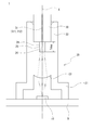
- An optical module 1 according to an embodiment of the present invention shown in FIG. 1 is used for optical communication in an automobile, and includes a light emitting element 10, a holder, and a ferrule 30.
- the light emitting element 10 is a member that emits light (laser light) constituting a signal to be transmitted. Specifically, it is a photoelectric conversion element that converts a signal to be transmitted from an electric signal to an optical signal and emits it. In the present embodiment, the light emitting element 10 is mounted on a substrate B on which a circuit that generates an electrical signal (transmits a signal to the light emitting element 10) is formed.
- the holder 20 is made of a material that transmits light emitted from the light emitting element 10 (light that transmits a signal) (for example, Terralink (registered trademark of Sumitomo Electric Fine Polymer Co., Ltd .; refractive index 1.51, other characteristics, etc.). : //www.sei-sfp.co.jp/products/tralink.html) and PEI (refractive index 1.64)).
- the holder 20 has a cylindrical portion 21 formed in a cylindrical shape (this embodiment is a cylindrical shape with a step) and a sleeve portion 22 that is also formed in a cylindrical shape.
- the cylindrical portion 21 is a portion surrounding the light emitting element 10 mounted on the substrate B.
- the tip of the cylindrical portion 21 is fixed by soldering or the like around the portion of the substrate B where the light emitting element 10 is mounted.
- a converging lens portion 23 is formed on the inner bottom surface (upper surface in FIG. 1) of the cylindrical portion 21.
- the converging lens part 23 is a convex lens through which divergent light (laser light having a predetermined divergence angle (divergence angle)) emitted from the light emitting element 10 located inside the cylindrical part 21 is transmitted.
- the divergent light entering the portion 23 is refracted so as to become focused light (laser light having a predetermined focusing angle) toward the end of an optical fiber 31 described later.
- the optical axis of the focusing lens unit 23 coincides with the optical axis of the light emitting element 10 (light emitted from the light emitting element 10) (optical axis X).
- the sleeve portion 22 is a portion into which a ferrule 30 having an optical fiber 31 fixed therein is inserted.
- the inner diameter is set to be substantially the same as the outer diameter of the ferrule 30 (set so that a gap is not generated as much as possible) between them.
- the inner diameter of the recess 24 is smaller than the inner diameter of the sleeve portion 22. Accordingly, there is a step between the recess 24 and the inner wall surface of the sleeve portion 22.
- the main component of the optical fiber 31 in this embodiment is glass (refractive index of 1.45 of the core 311 and refractive index of 1.46 to 1.53 of the clad 312), and is fixed to the center of the ferrule 30.
- the optical axis of the optical fiber 31 fixed to the ferrule 30 positioned with respect to the holder 20 coincides with the optical axis of the focusing lens unit 23 and the light emitting element 10 (light emitted from the light emitting element 10) (light Axis X).
- the end surface of the core 311 of the optical fiber 31 has a circular shape centered on a point intersecting the optical axis X.
- the end of the optical fiber 31 is exposed at the center of the front end surface of the ferrule 30 (the surface abutted against the step).
- the portion where the optical fiber 31 is exposed faces the space 25 inside the recess 24. More specifically, a portion (a part on the center side) including the exposed end portion of the optical fiber 31 on the tip surface of the ferrule 30 faces the space 25 inside the recess 24.
- the end portion of the optical fiber 31 does not contact the holder 20 when the ferrule 30 is inserted into the sleeve portion 22. That is, damage to the end of the optical fiber 31 is prevented.
- the divergent light emitted from the light emitting element 10 is focused by the focusing lens unit 23 and enters the optical fiber 31. That is, the optical signal output from the light emitting element 10 is transmitted to a light receiving element (not shown) through the optical fiber 31.
- the light focused by the focusing lens unit 23 is an interface 26 between the holder 20 intersecting the optical axis X and the space 25, that is, “light transmissive material constituting the holder 20” and “space” having different refractive indexes. 25 passes through the interface 26 of “substance present in 25”. Therefore, the emitted light is refracted at the interface 26.
- the interface 26 is a plane orthogonal to the optical axis X facing the tip surface of the ferrule 30, and has a circular shape centered at a point intersecting the optical axis X.
- the light 3B converged by the focusing lens unit 23 is the core 311 of the optical fiber 31 regardless of whether air is present in the space 25 or water generated by condensation or the like is present.
- the distance between the center of 311 and the center of the interface 26) “Tdep” satisfies the formula (4) (hereinafter, this condition is referred to as a first condition).
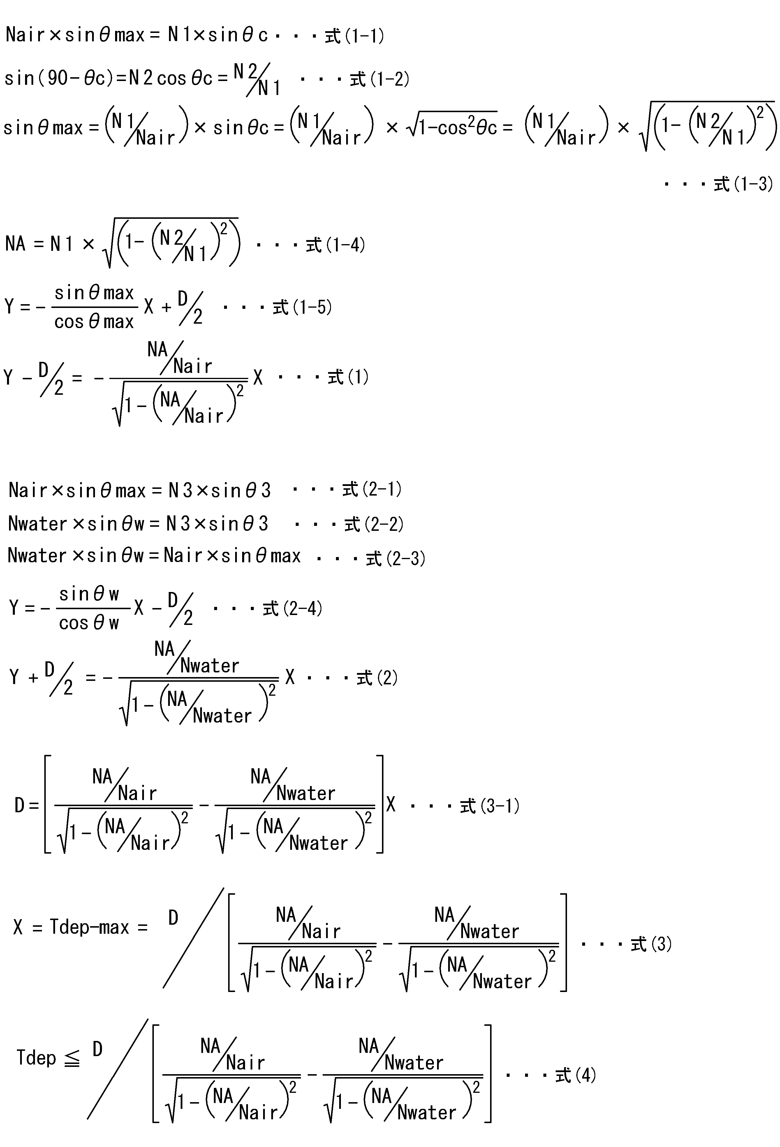
- Equation (4) is derived as follows. Regardless of whether air is present in the space 25 or water is present, the limit of light entering the core 311 of the optical fiber 31 is the outermost ray of focused light (hereinafter simply referred to as the optical fiber 31).
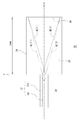
- the outermost light beam changes from a state where it is incident on one end of the core 311 to a state where it is incident on the other end of the core 311. That is, when air is present in the space 25, the light beam is indicated by a solid line in FIG. 2, whereas when water is present in the space 25, the light beam is changed to a light ray indicated by a dotted line in FIG.
- the axis along the optical axis is the X axis
- the axis along the end face of the core 311 perpendicular to the X axis is the Y axis
- the intersection of the two is the coordinate (0, 0).
- ) A light beam symmetric with respect to the optical axis (X axis) is defined as a formula (1 ′)
- a light beam in the case where water is present in the space 25 is expressed as a formula (2)
- Both lines can be derived as follows: D: diameter of the core 311; Nair: refractive index of air ( ⁇ 1); Nwater: refractive index of water ( ⁇ 1.33); N1: refractive index of the material constituting the core 311; N2: cladding 312. Refractive index of the constituent material, N3: Refractive index of the constituent material of the holder 20, NA: Numerical aperture of the core 311, ⁇ : Inclination angle of the light beam with respect to the optical axis (X axis
- the light beam that has entered the core 311 is designed to remain in the core 311. That is, it is set as a light beam totally reflected at the interface 26 between the core 311 and the clad 312 in the optical fiber 31 (so as not to pass through the interface 26 and enter the clad 312).
- the condition under which the light beam having the angle ⁇ c is totally reflected at the interface 26 between the core 311 and the clad 312 is Expression (1-2).
- the straight line of the formula (1) is a straight line having an intercept of the radius D / 2 of the core 311 and an inclination of ⁇ tan ⁇ max, and is represented by the formula (1-5).
- this formula (1-5) is put together using formula (1-3) and formula (1-4), formula (1) is obtained.
- Equation (2-1) is obtained from the law of refraction at the interface 26 between the space 25 and the holder 20 (the bottom surface of the recess 24) when air exists in the space 25. Further, when water is present in the space 25, the equation (2-2) is obtained by the law of refraction at the interface 26 between the space 25 and the holder 20. Summarizing formulas (2-1) and (2-2) yields formula (2-3). Note that ⁇ 3 is an inclination angle with respect to the optical axis (X axis) of the light beam passing through the holder 20, and ⁇ w is an inclination angle with respect to the optical axis (X axis) of the light beam passing through the space 25 where water exists.
- the straight line in the formula (2) is a straight line having an intercept of the radius of the core 311 ⁇ D / 2 and an inclination of ⁇ tan ⁇ max, and thus is represented by the formula (2-4).
- Formula (3-1) is obtained by formula (2) -formula (1).
- Expression (3) is obtained by transforming Expression (3-1) and summing up X.
- the X is an X value at the limit at which light enters the core 311 of the optical fiber 31 regardless of whether air is present in the space 25 or water is present. That is, the depth of the recess 24 at the limit (the maximum depth Tdep-max of the recess 24). Therefore, the depth Tdep of the recess 24 should be set so as to satisfy the relationship of Expression (4) so that all of the focused light that has passed through the focusing lens unit 23 enters the optical fiber 31. become.
- Tdep-max is determined by the numerical aperture NA of the core 311 of the optical fiber 31 and the radius 3/2 of the core 311 of the optical fiber 31.
- the horizontal axis represents the NA value
- the vertical axis represents Tdep / D (ratio between the maximum depth of the recess 24 and the diameter of the core 311 of the optical fiber 31).
- Tdep ⁇ max ⁇ 2.7 ⁇ (NA ⁇ 0.05) ⁇ 1.4 ).
- the graph shows the range of the numerical aperture “0.15 ⁇ NA ⁇ 0.45” of a general glass fiber.
- the value (diameter) of the interface 26 (the bottom surface of the recess 24) between the space 25 and the holder 20 is substituted by substituting the value into the above equation (3).
- Dm can be determined.
- the horizontal axis indicates the NA value
- the vertical axis indicates the change in Dm represented by Dm / D (ratio between the diameter of the bottom surface of the recess 24 and the diameter of the core 311 of the optical fiber 31).
- the diameter Dm of the bottom surface of the concave portion 24 that is the interface 26 between the space 25 and the holder 20 does not greatly depend on NA, and It can be seen that it may be five times or more the diameter D of the core 311 of the fiber 31.
- ⁇ Second condition> The second condition, which is a more severe condition than the first condition, will be described.
- Expression (4) of the first condition is the minimum condition under which the outermost ray of the focused light is incident on the core 311 regardless of whether air is present in the space 25 or water is present. Is calculated as follows. On the other hand, as shown in FIG. 4, it is more preferable to set conditions so that light rays in the case where air exists in the space 25 are incident on the center of the core 311 (point of coordinates (0, 0)). .
- the formula (1a) shown in FIG. 4 is obtained by setting the intercept ( ⁇ D / 2) to 0 in the above formula (1).
- formula (2) -formula (1a) and X (Tdep) are summarized, formula (4a) of the second condition is obtained.
- the range of Tdep that can be set is smaller than that of the first condition, the optical module 1 is obtained which is strong against optical axis misalignment and the like and has a small loss even when water enters the recess 24.
- Equation (4) of the first condition is calculated as a condition that the outermost ray of the focused light is incident on the core 311 regardless of whether air is present in the space 25 or water is present. Is. That is, the condition is such that no loss occurs even when water enters the space 25.
- the depth of the recess 24 is set as follows. It is possible to set.
- the outermost light beam on one side of the optical axis is located at one end of the core 311 and the outermost light beam on the other side of the optical axis. Assume that the light beam reaches the other end of the core 311.
- the outermost light beam on one side of the optical axis is at a point away from the center of the core 311 on the one side by D / ⁇ 2 on the other side of the optical axis. It is assumed that the outermost light beam at reaches a point D / ⁇ 2 away from the center of the core 311 on the other side.
- the area of the end surface of the core 311 is set to be twice.
- the portion on the optical axis side where the optical power is high is incident on the core 311 (at least half of the optical energy is incident on the core 311). Conditions can be applied.
- the formula (1b) shown in FIG. 5 is obtained by setting the intercept ( ⁇ D / 2) to D / 2 in the above formula (1). Further, the expression (2b) is obtained by setting the intercept (D / 2) to D / ⁇ 2 in the above expression (2).
- Expression (4b) of the third condition is obtained. This condition has a smaller Tdep range that can be set than the first condition and the second condition.
- the optical path of the optical module 1 on the exit side when air is present in the space 25 can be made the same as the optical path of the optical module 9 on the incident side (in a symmetrical manner).
- the incident-side optical module 9 includes a converging lens unit 93 that focuses the light emitted from the optical fiber 31 toward the light receiving element 91.
- Tdep is about 0.15 mm or less. That is, when the main component of the optical fiber 31 is glass and the diameter of the core 311 is 50 ⁇ m or more, it is desirable to set the distance from the interface with the space to the end of the optical fiber to 0.15 mm or less.
- the lower limit value of Tdep ( ⁇ 0) is set as a value that can prevent contact between the end face of the optical fiber and the holder. In order to reliably prevent contact, it may be 10 ⁇ m or more. More preferably, it is 50 ⁇ m or more.
- the shape of the illustrated holder 20 and the specification of the light emitting element 10 can be appropriately changed without departing from the gist of the present invention.
- the recessed part 24 formed in the holder 20 demonstrated that it was formed in order to prevent the damage of the optical fiber 31 end part by the end part of the optical fiber 31 and the holder 20 contacting
- the purpose of forming the recess 24 is not limited to this. That is, the technical idea of the present invention can be applied as long as the interface 26 between the material constituting the holder 20 and the air exists in the optical path from the light emitting element 10 to the optical fiber 31. Furthermore, the technical idea of the present invention can be applied even when a substance other than air (excluding the material constituting the holder 20) is present in the recess 24. In other words, any configuration may be used as long as the recess 26 formed in the holder 20 forms the interface 26 in which reflection occurs in the optical path from the light emitting element 10 to the optical fiber 31.
Landscapes
- Physics & Mathematics (AREA)
- General Physics & Mathematics (AREA)
- Optics & Photonics (AREA)
- Optical Couplings Of Light Guides (AREA)
- Semiconductor Lasers (AREA)
Abstract
光モジュール1が備えるホルダ20には、発光素子10から出射された光を光ファイバ31の端部に向けて集束させる集束レンズ部23、及び、フェルール30の先端面における露出した前記光ファイバ端部を含む部分に面する空間25が形成されている。前記ホルダを構成する材料と前記空間との界面26から前記光ファイバ端部までの距離Tdepは、前記空間が、空気又は水のいずれで満たされている場合であっても、前記集束レンズ部を通過して前記界面に到達した光が、前記光ファイバ端面に集光されるように、設定される。前記光モジュールによれば、結露等によって空間内に水が発生しても、損失の増大を抑制することができる。
Description
本発明は、光信号を伝送するために用いられる光モジュールに関する。
例えば、下記特許文献1には、フェルールが挿入される筒状部分(スリーブ部)の底面に、光ファイバ端面との接触を防ぐ空間(凹部)が形成されたホルダを有する光モジュールが記載されている。
この空間は、発光素子から出射された光が光ファイバに至るまでの光路となる箇所である。そのため、ホルダを構成する材料と空間内の空気との界面(凹部の底面)で生ずる屈折を考慮してレンズ等が設計される。
しかし、当該空間内が結露などによって生ずる水で満たされることがある(特に、自動車内の光通信に用いられる光モジュールなどでは、温度、湿度変化による結露が発生しやすい)。当該空間が水で満たされてしまうと、上記界面における屈折角度が変化してしまい、光モジュールにおける損失(結合損失)が大きくなってしまうという問題があった。
本発明が解決しようとする課題は、光ファイバ端部に面する空間が形成されたホルダを備えた光モジュールにおいて、当該空間内に水が発生することによる損失の増大を抑制することにある。
本発明にかかる光モジュールは、光軸上に発光部が位置する発光素子と、この発光素子から出射された光を透過する材料からなるホルダと、先端面で端部が露出するように光ファイバを保持し、この光ファイバが光軸に沿うように前記ホルダに取り付けられたフェルールと、を備え、前記ホルダには、前記発光素子から出射された光を前記光ファイバの端部に向けて集束させる集束レンズ部、および前記フェルールの先端面における露出した光ファイバ端部を含む部分に面する空間が形成されており、前記ホルダを構成する材料と前記空間との界面であって、前記フェルールの先端面と対向する界面から前記光ファイバ端部までの距離Dは、後述する式(4)を満たすことを特徴とする。
また、前記ホルダを構成する材料と前記空間との界面から前記光ファイバ端部までの距離Tdepは、後述する式(4a)を満たすようにしてもよい。
また、前記ホルダを構成する材料と前記空間との界面から前記光ファイバ端部までの距離Tdepは、後述する式(4b)を満たすようにしてもよい。
前記光ファイバのコアの直径が50μm以上であり、当該光ファイバの主成分がガラスである場合において、前記ホルダを構成する材料と前記空間との界面から前記光ファイバ端部までの距離Tdepは、0.15mm以下であるとよい。
本発明にかかる光モジュールでは、空間が空気で満たされている場合、水で満たされている場合のいずれの場合であっても、集束レンズ部を通過して界面に到達した光は光ファイバ端面に集光されることになる。したがって、結露等によって空間内に水が発生することによる損失の増大を抑制することができる。
以下、本発明の各実施形態について図面を参照して詳細に説明する。図1に示す本発明の一実施形態にかかる光モジュール1は、自動車内における光通信に用いられるものであり、発光素子10、ホルダ、およびフェルール30を備える。
発光素子10は、伝送すべき信号を構成する光(レーザ光)を出射する部材である。具体的には、伝送すべき信号を電気信号から光信号に変換して出射する光電変換素子である。本実施形態では、発光素子10は、電気信号を生成する(信号を発光素子10に伝える)回路が形成された基板Bに実装されている。
ホルダ20は、発光素子10から出射された光(信号を伝送する光)を透過する材料(例えばテラリンク(住友電工ファインポリマー株式会社の登録商標;屈折率1.51、その他の特性等はhttp://www.sei-sfp.co.jp/products/tralink.html参照)やPEI(屈折率1.64))で形成された部材である。ホルダ20は、筒状に形成された筒状部21(本実施形態は段差のある筒状である)および同じく筒状に形成されたスリーブ部22を有する。筒状部21は上記基板Bに実装された発光素子10を囲む部分である。具体的には、筒状部21の先端が基板Bにおける発光素子10が実装された箇所の周囲にハンダ付け等により固定されている。筒状部21の内底面(図1では上側の面)には、集束レンズ部23が形成されている。集束レンズ部23は、筒状部21の内側に位置する上記発光素子10から出射された発散光(所定の広がり角(発散角)をもつレーザ光)が透過する凸レンズであって、当該集束レンズ部23に進入する発散光が後述する光ファイバ31端部に向かう集束光(所定の集束角をもつレーザ光)となるように屈折させる。この集束レンズ部23の光軸は、発光素子10(発光素子10から出射される光)の光軸と一致している(光軸X)。
スリーブ部22は、内側に光ファイバ31が固定されたフェルール30が挿入される部分である。その内径はフェルール30の外径と略同じに設定(両者の間にできるだけ隙間が生じないように設定)されている。スリーブ部22の内底面(図1では下側の面)には、発光素子10側(集束レンズ部23側)に向かって窪んだ凹部24が形成されている。凹部24の内径は、スリーブ部22の内径よりも小さい。したがって、凹部24とスリーブ部22の内壁面との間には段差が存在する。スリーブ部22の内側にフェルール30を挿入すると、フェルール30の周縁が当該段差(スリーブ部22の内底面)に突き当たる。当該突き当たる位置までフェルール30を挿入することにより、ホルダ20に対するフェルール30が位置決めされる。本実施形態における光ファイバ31は、主成分がガラス(コア311の屈折率1.45、クラッド312の屈折率1.46~1.53)であり、フェルール30の中央に固定されている。ホルダ20に対して位置決めされたフェルール30に固定されている光ファイバ31の光軸は、上記集束レンズ部23や発光素子10(発光素子10から出射される光)の光軸と一致する(光軸X)。この光ファイバ31のコア311の端面は、光軸Xと交差する点を中心とする円形である。
フェルール30の先端面(上記段差に突き当てられる面)の中央には、光ファイバ31の端部が露出している。この光ファイバ31が露出した箇所は、上記凹部24の内側の空間25に面する。さらに詳しく言えば、フェルール30の先端面における露出した光ファイバ31の端部を含む部分(中央側の一部)が、上記凹部24の内側の空間25に面する。このような空間25が形成されていると、フェルール30が上記スリーブ部22に挿入される際、光ファイバ31の端部がホルダ20に接触することはない。つまり、光ファイバ31端部の損傷が防止される。
このような構成の光モジュール1において、上記発光素子10から出射された発散光は、集束レンズ部23によって集束されて光ファイバ31に進入する。すなわち、発光素子10から出力された光信号が、光ファイバ31を通じて図示されない受光素子に伝達される。このとき、集束レンズ部23によって集束された光は、光軸Xに交差するホルダ20と上記空間25との界面26、すなわち屈折率の異なる「ホルダ20を構成する光透過性材料」と「空間25内に存在する物質」の界面26を通過する。そのため、当該界面26で出射光が屈折する。当該界面26は、フェルール30の先端面と対向する光軸Xに直交する平面であり、光軸Xに交差する点を中心とする円形である。
本実施形態では、空間25内に空気が存在している場合および結露等によって生じる水が存在している場合のいずれであっても、集束レンズ部23によって集束する光が光ファイバ31のコア311に進入することとなるように、凹部24の深さ、すなわちホルダ20を構成する材料と空間25との界面26から光ファイバ31端部までの距離(光軸Xに交差する光ファイバ31のコア311の中心と界面26の中心間の距離)「Tdep」が式(4)を満たす(以下、当該条件を第一条件と称する)ように設定している。
<第一条件>
式(4)は、以下のように導出したものである。空間25内に空気が存在する場合と水が存在する場合のいずれであっても光ファイバ31のコア311に光が進入する限界は、光ファイバ31に向かう集束光の最も外側の光線(以下単に光線というときはこの最も外側の光線をいうものとする)が、コア311の一方側端部に入射する状態からコア311の他方側端部に入射する状態に変化するときである。すなわち、空間25内に空気が存在する場合には図2において実線で示す光線となる一方、空間25内に水が存在する場合には図2において点線で示す光線に変化する場合である。光軸に沿う軸をX軸、それに直交するコア311の端面に沿う軸をY軸、両者の交点を座標(0,0)とし、空間25内に空気が存在する場合の光線を式(1)(光軸(X軸)に関し対称な光線を式(1′)とする)で示される直線とし、空間25内に水が存在する場合の光線を式(2)(光軸(X軸)に関し対称な光線式(2′)とする)の直線としたとき、両式は以下のように導出できる。なお、D;コア311の直径、Nair;空気の屈折率(≒1)、Nwater;水の屈折率(≒1.33)、N1;コア311を構成する材料の屈折率、N2;クラッド312を構成する材料の屈折率、N3;ホルダ20を構成する材料の屈折率、NA;コア311の開口数、θ;光軸(X軸)に対する光線の傾斜角度とする。
式(4)は、以下のように導出したものである。空間25内に空気が存在する場合と水が存在する場合のいずれであっても光ファイバ31のコア311に光が進入する限界は、光ファイバ31に向かう集束光の最も外側の光線(以下単に光線というときはこの最も外側の光線をいうものとする)が、コア311の一方側端部に入射する状態からコア311の他方側端部に入射する状態に変化するときである。すなわち、空間25内に空気が存在する場合には図2において実線で示す光線となる一方、空間25内に水が存在する場合には図2において点線で示す光線に変化する場合である。光軸に沿う軸をX軸、それに直交するコア311の端面に沿う軸をY軸、両者の交点を座標(0,0)とし、空間25内に空気が存在する場合の光線を式(1)(光軸(X軸)に関し対称な光線を式(1′)とする)で示される直線とし、空間25内に水が存在する場合の光線を式(2)(光軸(X軸)に関し対称な光線式(2′)とする)の直線としたとき、両式は以下のように導出できる。なお、D;コア311の直径、Nair;空気の屈折率(≒1)、Nwater;水の屈折率(≒1.33)、N1;コア311を構成する材料の屈折率、N2;クラッド312を構成する材料の屈折率、N3;ホルダ20を構成する材料の屈折率、NA;コア311の開口数、θ;光軸(X軸)に対する光線の傾斜角度とする。
(式(1)の導出)
空間25内に空気が存在する場合、空間25と光ファイバ31のコア311との界面26における屈折の法則より式(1-1)が得られる。なお、θmax;空気が存在する空間25内を通過する光線の光軸(X軸)に対する傾斜角度、θc;コア311内の光線の光軸(X軸)に対する傾斜角度である。
空間25内に空気が存在する場合、空間25と光ファイバ31のコア311との界面26における屈折の法則より式(1-1)が得られる。なお、θmax;空気が存在する空間25内を通過する光線の光軸(X軸)に対する傾斜角度、θc;コア311内の光線の光軸(X軸)に対する傾斜角度である。
コア311内に進入した光線は、コア311内に留まるように設計される。つまり、光ファイバ31におけるコア311とクラッド312の界面26で全反射する光線として(当該界面26を通過しクラッド312内に進入しないように)設定される。コア311とクラッド312の界面26において角度θcの光線が全反射する条件は式(1-2)である。
式(1-1)と式(1-2)をまとめるとsinθmaxについての式(1-3)が得られる。また、光ファイバ31(コア311)の開口数NAは式(1-4)で示される。
式(1)の直線は、切片がコア311の半径D/2であり、傾き-tanθmaxである直線であるため、式(1-5)で示される。この式(1-5)を式(1-3)および式(1-4)を使ってまとめると、式(1)が得られる。
(式(2)の導出)
空間25内に空気が存在する場合の、空間25とホルダ20の界面26(凹部24の底面)における屈折の法則より式(2-1)が得られる。また、空間25内に水が存在する場合の、空間25とホルダ20の界面26における屈折の法則により式(2-2)が得られる。式(2-1)と式(2-2)をまとめると、式(2-3)が得られる。なお、θ3;ホルダ20を通過する光線の光軸(X軸)に対する傾斜角度、θw;水が存在する空間25内を通過する光線の光軸(X軸)に対する傾斜角度である。
空間25内に空気が存在する場合の、空間25とホルダ20の界面26(凹部24の底面)における屈折の法則より式(2-1)が得られる。また、空間25内に水が存在する場合の、空間25とホルダ20の界面26における屈折の法則により式(2-2)が得られる。式(2-1)と式(2-2)をまとめると、式(2-3)が得られる。なお、θ3;ホルダ20を通過する光線の光軸(X軸)に対する傾斜角度、θw;水が存在する空間25内を通過する光線の光軸(X軸)に対する傾斜角度である。
式(2)の直線は、切片がコア311の半径-D/2であり、傾き-tanθmaxである直線であるため、式(2-4)で示される。この式(2-4)を式(2-3)、上記式(1-3)、(1-4)を使ってまとめると、式(2)が得られる。
(凹部の最大深さの導出)
式(2)-式(1)とすることにより式(3-1)が得られる。この式(3-1)を変形してXについてまとめると式(3)が得られる。当該Xは、空間25内に空気が存在する場合と水が存在する場合のいずれであっても光ファイバ31のコア311に光が進入する限界のときにおけるX値である。すなわち、当該限界のときにおける凹部24の深さ(凹部24の最大深さTdep-max)となる。したがって、集束レンズ部23を通過した集束光が全て光ファイバ31に進入するようにするためには、凹部24の深さTdepを、式(4)の関係を満たすように設定すればよいということになる。
式(2)-式(1)とすることにより式(3-1)が得られる。この式(3-1)を変形してXについてまとめると式(3)が得られる。当該Xは、空間25内に空気が存在する場合と水が存在する場合のいずれであっても光ファイバ31のコア311に光が進入する限界のときにおけるX値である。すなわち、当該限界のときにおける凹部24の深さ(凹部24の最大深さTdep-max)となる。したがって、集束レンズ部23を通過した集束光が全て光ファイバ31に進入するようにするためには、凹部24の深さTdepを、式(4)の関係を満たすように設定すればよいということになる。
Tdep-maxは、光ファイバ31のコア311の開口数NA、光ファイバ31のコア311半径D/2によって決まる。Nair=1、Nwater=1.33を代入し、横軸をNA値、縦軸をTdep/D(凹部24の最大深さと光ファイバ31のコア311の直径との比)で表すと、図3に示す曲線(Tdep-max≒2.7×(NA-0.05)-1.4)となる。なお、当該グラフは、一般的なグラスファイバの開口数「0.15<NA<0.45」の範囲を示している。
また、凹部24の深さを上記最大深さTdep-maxとする場合、上記式(3)にその値を代入すると、空間25とホルダ20の界面26(凹部24の底面)の広さ(直径Dm)を求めることができる。図3に示すグラフには、横軸をNA値、縦軸をDm/D(凹部24の底面の直径と光ファイバ31のコア311の直径との比)で表したDmの変化を示している。これによると、凹部24の深さを上記最大深さTdep-maxとする場合には、空間25とホルダ20の界面26である凹部24の底面の直径Dmは、NAに大きく依存せず、光ファイバ31のコア311の直径Dの五倍以上であればよいことがわかる。
以上のように、凹部24の深さ、すなわちホルダ20を構成する材料と空間25との界面26から光ファイバ31端部までの距離「Tdep」が上記式(4)を満たすことにより、空間25内に空気が存在する場合、空間25内に水が存在する場合のいずれにおいても、集束レンズ部23を通過して界面26に到達した集束光は全て光ファイバ31のコア311内に進入することとなる。よって、結露などによって空間25内が水で満たされた場合であってもそれを理由とする損失は発生しない。なお、上記式(4)で規定される第一条件を満たす設計とした場合、従来構成のホルダ20と比較して凹部24の深さはかなり浅いものとなる。
<第二条件>
上記第一条件をさらに厳しくした条件である第二条件について説明する。上記第一条件の式(4)は、空間25内に空気が存在する場合と水が存在する場合のいずれであっても、集束光の最も外側の光線がコア311に入射する最低限の条件として算出されるものである。これに対し、図4に示すように、空間25内に空気が存在する場合の光線がコア311の中心(座標(0,0)の地点)に入射するように条件を設定するとさらに好適である。通常の使用状態時(空間25内に空気が存在する場合)において、集束光の焦点がコア311の中心に位置するようにすれば、光軸ずれ等に強い(誤差の吸収能が高い)光モジュール1とすることができるからである。
上記第一条件をさらに厳しくした条件である第二条件について説明する。上記第一条件の式(4)は、空間25内に空気が存在する場合と水が存在する場合のいずれであっても、集束光の最も外側の光線がコア311に入射する最低限の条件として算出されるものである。これに対し、図4に示すように、空間25内に空気が存在する場合の光線がコア311の中心(座標(0,0)の地点)に入射するように条件を設定するとさらに好適である。通常の使用状態時(空間25内に空気が存在する場合)において、集束光の焦点がコア311の中心に位置するようにすれば、光軸ずれ等に強い(誤差の吸収能が高い)光モジュール1とすることができるからである。
図4に示す式(1a)は、上記式(1)において切片(-D/2)を0にしたものである。式(2)-式(1a)とし、X(Tdep)についてまとめると、第二条件の式(4a)が得られる。上記第一条件よりも設定可能なTdepの範囲は小さくなるが、光軸ずれ等に強く、かつ、凹部24に水が浸入しても損失が小さい光モジュール1が得られる。

<第三条件>
上記第一条件および第二条件をさらに厳しくした条件である第三条件について説明する。上記第一条件の式(4)は、空間25内に空気が存在する場合と水が存在する場合のいずれであっても、集束光の最も外側の光線がコア311に入射する条件として算出されるものである。すなわち、空間25内に水が浸入した場合であっても損失が生じないような条件である。これに対し、水が空間25内に水が浸入した場合にある程度の損失が生じてしまうことを許容した上で、光モジュールの製造を容易にするため、以下のように凹部24の深さを設定することが考えられる。
上記第一条件および第二条件をさらに厳しくした条件である第三条件について説明する。上記第一条件の式(4)は、空間25内に空気が存在する場合と水が存在する場合のいずれであっても、集束光の最も外側の光線がコア311に入射する条件として算出されるものである。すなわち、空間25内に水が浸入した場合であっても損失が生じないような条件である。これに対し、水が空間25内に水が浸入した場合にある程度の損失が生じてしまうことを許容した上で、光モジュールの製造を容易にするため、以下のように凹部24の深さを設定することが考えられる。
図5に示すように、空間25内に空気が存在している場合には、光軸の一方側における最も外側の光線がコア311の一方側端部に、光軸の他方側における最も外側の光線がコア311の他方側端部に到達するとする。一方、空間25内に水が存在している場合には、光軸の一方側における最も外側の光線が当該一方側におけるコア311の中心からD/√2離れた地点に、光軸の他方側における最も外側の光線が当該他方側におけるコア311の中心からD/√2離れた地点に到達するとする。すなわち、光ファイバ31に向かって集束する集束光のX=0の地点における断面積が、空間25内に空気が存在している場合にはコア311の端面の面積と同じになり、空間25内に水が存在している場合にはコア311の端面の面積の二倍になるように設定する。光パワーが高い光軸側の部分がコア311に入射する(少なくとも光エネルギの1/2がコア311に入射する)こととなるため、このように設定しても信号が伝達可能な場合に本条件を適用することができる。
図5に示す式(1b)は、上記式(1)において切片(-D/2)をD/2としたものである。また、式(2b)は、上記式(2)において切片(D/2)をD/√2としたものである。式(2b)-式(1b)とし、X(Tdep)についてまとめると、第三条件の式(4b)が得られる。本条件は、上記第一条件や第二条件よりも設定可能なTdepの範囲は小さい。しかし、図6に示すように、空間25内に空気が存在している場合における出射側の光モジュール1の光路を、入射側の光モジュール9の光路と同じにすることができる(対称形にすることができる)ため、第三条件を満たす光モジュール1のホルダ20をそのまま入射側の光モジュール9のホルダ92として適用することができる。すなわち、水が浸入した場合の損失を抑制しつつ、ホルダ等の部材の共通化を図ることができる。なお、入射側の光モジュール9は、光ファイバ31から出射された光を受光素子91に向かって集束させる集束レンズ部93を備えるものである。
当該第三条件において、光ファイバ31の主成分がガラス(開口数;0.20~0.25)であり、コア311の直径が50μmであるとすると、Tdepは約0.15mm以下となる。すなわち、光ファイバ31の主成分がガラスであり、コア311の直径が50μm以上である場合には、空間との界面から光ファイバ端部までの距離を0.15mm以下に設定することが望ましい。

上記第一条件~第三条件において、Tdep(≠0)の下限値は、光ファイバ端面とホルダの接触を防ぐことができる値として設定される。接触を確実に防止するためには10μm以上であればよい。さらに好ましくは50μm以上である。
以上、本発明の実施の形態について詳細に説明したが、本発明は上記実施の形態に何ら限定されるものではなく、本発明の要旨を逸脱しない範囲で種々の改変が可能である。
例えば、図示したホルダ20の形状や、発光素子10の仕様は、本発明の要旨を逸脱しない範囲で適宜変更可能である。
また、ホルダ20に形成される凹部24は、光ファイバ31の端部とホルダ20が接触することによる光ファイバ31端部の損傷を防止するために形成されるものであることを説明したが、凹部24が形成される目的はこれに限定されない。すなわち、発光素子10から光ファイバ31に至るまでの光路に、ホルダ20を構成する材料と空気の界面26が存在する構成であれば、本発明の技術思想は適用可能である。さらには凹部24内に空気以外の物質(ホルダ20を構成する材料を除く)が存在している場合であっても、本発明の技術思想は適用可能である。すなわち、ホルダ20に形成される凹部24によって、発光素子10から光ファイバ31に至るまでの光路に、反射が生ずる界面26が形成される構成であればどのような構成であってもよい。
Claims (4)
- 光軸上に発光部が位置する発光素子と、
この発光素子から出射された光を透過する材料からなるホルダと、
先端面で端部が露出するように光ファイバを保持し、この光ファイバが光軸に沿うように前記ホルダに取り付けられたフェルールと、
を備え、
前記ホルダには、前記発光素子から出射された光を前記光ファイバの端部に向けて集束させる集束レンズ部、および前記フェルールの先端面における露出した光ファイバ端部を含む部分に面する空間が形成されており、
前記ホルダを構成する材料と前記空間との界面であって、前記フェルールの先端面と対向する界面から前記光ファイバ端部までの距離Tdepは、以下の式を満たすことを特徴とする光モジュール。
ただし、以下の式において、D;光ファイバのコアの直径、NA;光ファイバの開口数、Nair;空気の屈折率、Nwater;水の屈折率、である。

- 前記ホルダを構成する材料と前記空間との界面から前記光ファイバ端部までの距離Tdepは、以下の式を満たすことを特徴とする請求項1に記載の光モジュール。
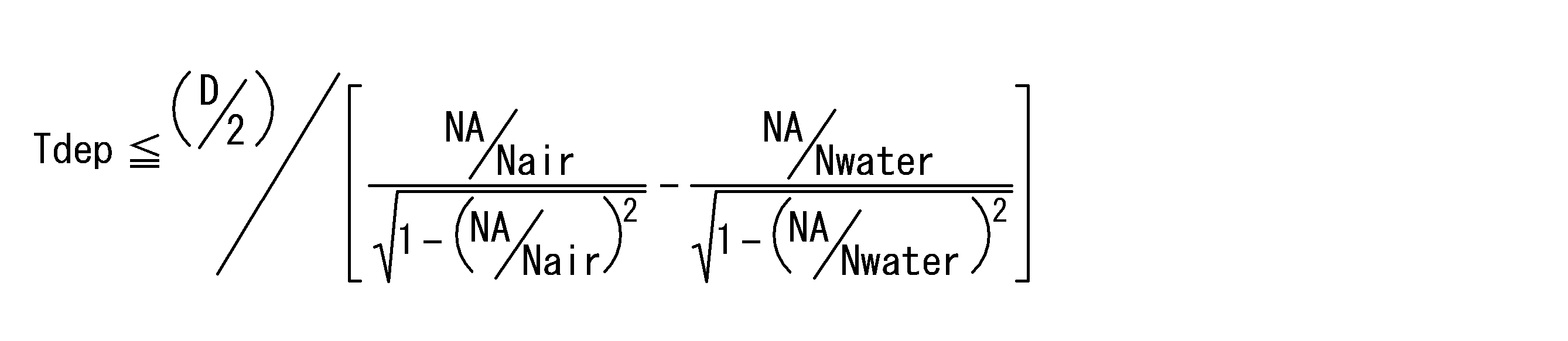
- 前記ホルダを構成する材料と前記空間との界面から前記光ファイバ端部までの距離Tdepは、以下の式を満たすことを特徴とする請求項2に記載の光モジュール。

- 前記光ファイバのコアの直径が50μm以上であり、当該光ファイバの主成分がガラスである場合において、前記ホルダを構成する材料と前記空間との界面から前記光ファイバ端部までの距離Tdepは、0.15mm以下であることを特徴とする請求項3に記載の光モジュール。
Applications Claiming Priority (2)
| Application Number | Priority Date | Filing Date | Title |
|---|---|---|---|
| JP2013030982A JP2014160179A (ja) | 2013-02-20 | 2013-02-20 | 光モジュール |
| JP2013-030982 | 2013-12-27 |
Publications (1)
| Publication Number | Publication Date |
|---|---|
| WO2014129281A1 true WO2014129281A1 (ja) | 2014-08-28 |
Family
ID=51391077
Family Applications (1)
| Application Number | Title | Priority Date | Filing Date |
|---|---|---|---|
| PCT/JP2014/052033 Ceased WO2014129281A1 (ja) | 2013-02-20 | 2014-01-30 | 光モジュール |
Country Status (2)
| Country | Link |
|---|---|
| JP (1) | JP2014160179A (ja) |
| WO (1) | WO2014129281A1 (ja) |
Citations (2)
| Publication number | Priority date | Publication date | Assignee | Title |
|---|---|---|---|---|
| JP2005148116A (ja) * | 2003-11-11 | 2005-06-09 | Mitsubishi Cable Ind Ltd | 光ファイバ |
| JP2012237819A (ja) * | 2011-05-10 | 2012-12-06 | Sumitomo Electric Ind Ltd | 光モジュール用フォルダ |
-
2013
- 2013-02-20 JP JP2013030982A patent/JP2014160179A/ja active Pending
-
2014
- 2014-01-30 WO PCT/JP2014/052033 patent/WO2014129281A1/ja not_active Ceased
Patent Citations (2)
| Publication number | Priority date | Publication date | Assignee | Title |
|---|---|---|---|---|
| JP2005148116A (ja) * | 2003-11-11 | 2005-06-09 | Mitsubishi Cable Ind Ltd | 光ファイバ |
| JP2012237819A (ja) * | 2011-05-10 | 2012-12-06 | Sumitomo Electric Ind Ltd | 光モジュール用フォルダ |
Also Published As
| Publication number | Publication date |
|---|---|
| JP2014160179A (ja) | 2014-09-04 |
Similar Documents
| Publication | Publication Date | Title |
|---|---|---|
| JP6461509B2 (ja) | 光レセプタクルおよび光モジュール | |
| JP6490432B2 (ja) | 照明装置 | |
| WO2014180024A1 (zh) | 透镜光学设备及基于透镜光学设备的光路传播方法 | |
| US9341796B2 (en) | Optical coupler and photoelectric conversion device having same | |
| CN102565968B (zh) | 光纤通信装置 | |
| CN102436038A (zh) | 光路耦合器件、光路耦合装置及光路耦合方法 | |
| TWI515465B (zh) | 光耦合元件及應用光耦合元件之光學模組 | |
| US11025030B2 (en) | Optical module | |
| WO2020011032A1 (zh) | 光模块 | |
| US20130294726A1 (en) | Optical module having enhanced optical coupling efficiency between laser diode and optical fiber | |
| CN110806623A (zh) | 光收发器件 | |
| US20120314996A1 (en) | Optical fiber communication apparatus | |
| TWI493896B (zh) | 光纖通訊裝置 | |
| CN110476096A (zh) | 平面光波导及光学模块 | |
| JP2015018039A (ja) | 光モジュール | |
| KR20140034681A (ko) | 광학 분할 장치 | |
| CN108490537A (zh) | 光模块 | |
| CN108490556A (zh) | 光模块 | |
| WO2014129281A1 (ja) | 光モジュール | |
| US10466426B2 (en) | Optical fiber drawer structure and optical module | |
| US20130308905A1 (en) | Optical fiber and light coupling system using same | |
| WO2014112282A1 (ja) | 光モジュールおよび光モジュールユニット | |
| KR20190088265A (ko) | 빔집속장치 | |
| WO2018221401A1 (ja) | 光レセプタクルおよび光モジュール | |
| TWI542914B (zh) | 光波導連接器 |
Legal Events
| Date | Code | Title | Description |
|---|---|---|---|
| 121 | Ep: the epo has been informed by wipo that ep was designated in this application |
Ref document number: 14754168 Country of ref document: EP Kind code of ref document: A1 |
|
| NENP | Non-entry into the national phase |
Ref country code: DE |
|
| 122 | Ep: pct application non-entry in european phase |
Ref document number: 14754168 Country of ref document: EP Kind code of ref document: A1 |