WO2014129271A1 - 自動分析装置 - Google Patents
自動分析装置 Download PDFInfo
- Publication number
- WO2014129271A1 WO2014129271A1 PCT/JP2014/051878 JP2014051878W WO2014129271A1 WO 2014129271 A1 WO2014129271 A1 WO 2014129271A1 JP 2014051878 W JP2014051878 W JP 2014051878W WO 2014129271 A1 WO2014129271 A1 WO 2014129271A1
- Authority
- WO
- WIPO (PCT)
- Prior art keywords
- inspection
- sample
- test sample
- unit
- time
- Prior art date
- Legal status (The legal status is an assumption and is not a legal conclusion. Google has not performed a legal analysis and makes no representation as to the accuracy of the status listed.)
- Ceased
Links
Images




Classifications
-
- G—PHYSICS
- G01—MEASURING; TESTING
- G01N—INVESTIGATING OR ANALYSING MATERIALS BY DETERMINING THEIR CHEMICAL OR PHYSICAL PROPERTIES
- G01N35/00—Automatic analysis not limited to methods or materials provided for in any single one of groups G01N1/00 - G01N33/00; Handling materials therefor
- G01N35/00584—Control arrangements for automatic analysers
- G01N35/00594—Quality control, including calibration or testing of components of the analyser
- G01N35/00613—Quality control
-
- G—PHYSICS
- G01—MEASURING; TESTING
- G01N—INVESTIGATING OR ANALYSING MATERIALS BY DETERMINING THEIR CHEMICAL OR PHYSICAL PROPERTIES
- G01N35/00—Automatic analysis not limited to methods or materials provided for in any single one of groups G01N1/00 - G01N33/00; Handling materials therefor
- G01N35/00584—Control arrangements for automatic analysers
- G01N35/00594—Quality control, including calibration or testing of components of the analyser
- G01N35/00613—Quality control
- G01N35/00663—Quality control of consumables
-
- G—PHYSICS
- G01—MEASURING; TESTING
- G01N—INVESTIGATING OR ANALYSING MATERIALS BY DETERMINING THEIR CHEMICAL OR PHYSICAL PROPERTIES
- G01N35/00—Automatic analysis not limited to methods or materials provided for in any single one of groups G01N1/00 - G01N33/00; Handling materials therefor
- G01N35/00584—Control arrangements for automatic analysers
- G01N35/00594—Quality control, including calibration or testing of components of the analyser
- G01N35/00613—Quality control
- G01N35/00663—Quality control of consumables
- G01N2035/00673—Quality control of consumables of reagents
Definitions
- This relates to a device that automatically samples and analyzes samples requested for inspection.
- the procedure from the inspection request to the start of the inspection of the automatic analyzer for analyzing a biological sample is as follows: 1) Input the inspection request, 2) Press the request registration button, and the user puts the inspection sample into the apparatus. Erection. When a large number of inspection samples are requested to be inspected and all the measuring units are measuring, the inspection samples are in a waiting state for inspection. After completion of the measurement by the measurement unit, the analysis process of the test sample waiting for measurement is started and sampled from the test sample container.
- the reagent used for the inspection has an expiration date, and as background art related thereto, there is, for example, Japanese Patent Application Laid-Open No. 2010-281845.
- the reagent kit is Acquire identification information including the measurement item to be used and the expiration date of the reagent kit, set the expiration date after opening the reagent of the reagent kit, and set the expiration date and the set expiration date after opening the reagent included in the identification information.
- the earlier of the expiration date is set as the expiration date and displayed on the display unit together with the measurement item included in the identification information (summary).
- expiration dates are set for test samples and reagents installed in the device after the device is installed until the test sample and reagent can be used for analysis. If the test sample and reagent have a use time limit after the installation of the apparatus, in the conventional operation, the test sample and reagent use time may expire while the test sample is waiting for analysis in the apparatus. Specifically, after requesting more than the number of measurement positions that can measure an inspection item with an analysis time of 3 hours at a time in the device, the waiting time for analysis will be nearly 3 hours for subsequent requests. If an inspection sample with a usage time of 2 hours is requested after the installation of the device, the usage time will expire during the measurement waiting time.
- an object of the present invention is to provide an automatic analyzer that solves one or more of the above-described problems and improves the user-friendliness regarding the expiration date of the test sample or reagent.
- the present invention adopts the configuration described in the claims.
- a specific example is the measurement unit that measures the test sample, the test sample that is installed before the measurement by the measurement unit, and controls the introduction to the measurement unit, and the test sample can be measured by the measurement unit
- the time required for the test sample is compared with the expiry date of the test sample, and the test sample is installed in the test sample mounting portion at a timing at which the measurement sample can be measured by the measurement unit before the expiry date of the test sample.
- the user-friendliness regarding the expiration date of the test sample or reagent is improved.
- the timing at which the inspector installs the inspection sample can be known.
- FIG. 1 shows an outline as one form for carrying out the present embodiment
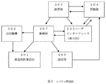
- FIG. 2 shows an example of a system configuration
- at least an inspection sample erection unit 201 that can control introduction of an inspection sample by an inspector
- a dispensing mechanism 202 that can sample from the inspection sample
- a user interface 203 that can request an inspection, and details of inspection items to be requested
- a storage unit 204 that stores information
- a calculation unit 205 that calculates a measurement timing
- a measurement unit 206 that analyzes a test sample
- a control unit 207 that integrates and controls them
- an inspector requests the test sample from the user interface 203 Is input and the check button is pressed
- the apparatus confirms the expiration date at the time of installation of each test sample from the detailed information of the requested test item stored in the storage unit 204
- the calculation unit 205 is in the process of testing.
- This example has resulted in this example as a result of various investigations for operating a test sample having an expiration date after erection of the device so that the expiration date on the device does not expire.
- This embodiment can control the introduction of a test sample. It is only necessary to be able to control the introduction of a new inspection sample by an inspector based on the expiration date after installation of the apparatus for a new inspection sample and the availability of the measuring unit 206 being inspected. Not.
- an inspection sample erection unit 201 that can control the erection of an inspection sample by an inspector
- a dispensing mechanism 202 that can sample from the inspection sample
- a user interface 203 that can request an inspection or a request.
- a storage unit 204 that stores detailed information of a requested inspection item and a requested inspection item
- a calculation unit 205 that calculates the installation timing of the requested inspection sample
- a measurement unit 206 that measures the inspection sample, and these are integratedly controlled. It is comprised by the control part 207.
- the inspection sample erection unit 201 in the present embodiment is a mechanism that allows the inspector to lay the inspection sample container, and may be any mechanism or operation that prevents the inspector from laying the inspection sample, and is described in the present embodiment.
- the shape of the inspection sample erection part 201 and the operation and mechanism for preventing the sample erection in the inspection are not limited to this embodiment.
- the test sample erection unit 201 has a drawer-like shape (hereinafter referred to as a drawer), and the shape inside the drawer can be directly erected with a test sample container.
- the shape may be a simple shape or a shape in which an inspection sample rack can be installed.
- the inspection sample erection part 201 has a disk shape and has an inspection sample introduction slot mechanism. When an inspection sample rack is placed in the inspection sample introduction slot, a disk shape is obtained. The inspection sample erection unit 201 is introduced. The introduction slot has a shutter that suppresses introduction of the inspection sample by the inspector, and when the introduction of the inspection sample is suppressed, the shutter is closed.
- the test sample erection unit 201 is a lane into which a test sample rack is introduced, and the test sample rack can be introduced by inserting the rack into the lane. And has a mechanism that can suppress the introduction of the inspection sample at the entrance of the inspection sample rack introduction lane.
- the inspection sample in the present embodiment is not particularly limited to the type and properties of the inspection sample as long as the installation time from the installation of the apparatus to the inspection is limited. More specific examples include RNA samples that are easily degraded by RNA-degrading enzymes, DNA samples that are easily degraded by DNA-degrading enzymes, and serum, plasma, urine, and the like that include proteins that are easily degraded.
- the inspection sample rack in the present embodiment is a rack in which an inspection sample container containing the above inspection sample can be installed, and a plurality of inspection sample containers may be installed.
- the dispensing mechanism 202 in the present embodiment may have any configuration as long as the inspection sample can be sampled from the inspection sample container, and the configuration is not limited to the present embodiment. As a more specific example, it has a fitting that can be attached with a detachable dispensing tip and a syringe mechanism that can suck and discharge liquid, and after the fitting is attached, the tip is inserted into the test sample and the syringe is inserted. The sample can be sucked by the suction operation. More preferably, the dispensing tip has electrical conductivity and has a liquid level detection function by a capacitive method.
- the user interface 203 in this embodiment has at least a function that enables an inspector to input the contents of an inspection request for a new inspection sample, and a function that can confirm the installation timing of the apparatus for a new inspection sample that has been input the inspection request contents. More preferably, it has a function that can display the timing at which a new inspection sample can be installed for a time, a function that can confirm an inspection request, and a time display from the confirmation of the request to the start of the inspection.
- the storage unit 204 that stores the detailed information of the inspection item to be mounted in the present embodiment may have any configuration as long as it can store the detailed information of the inspection item, and the type of the storage medium is limited to this embodiment. Not what you want.
- the storage unit 204 stores information necessary for inspection for each inspection item. At least the stability time (expiration date) information and measurement time information of the sample specified as the inspection item are stored.
- the calculation unit 205 and the user interface 203 can access each other, and the assumed information from the measurement unit 206 can be stored.
- the calculation unit 205 in the present embodiment is mainly composed of a CPU, but the calculation unit 205 confirms the expiration date at the time of erection of each inspection sample from the detailed information of the requested inspection item, and further inspecting
- the configuration of the calculation unit 205 does not limit the present embodiment as long as the availability of the measurement unit 206 can be confirmed and the timing at which a newly requested test sample can be installed can be calculated. More specifically, the calculation unit 205 determines the processing time of the inspection sample currently being measured and waiting for measurement based on the information on the inspection item requested from the inspection item database in the storage unit 204 and the measurement unit 206. The processing start time of the requested inspection sample can be calculated from the measurement time. Then, the calculation result can be returned to the user interface 203 and displayed on the user interface 203.
- the measurement unit 206 in the present embodiment only needs to be able to measure the sampled sample and reagent mixture, and the present embodiment is not limited to any mechanism.
- the measuring unit 206 is a rotary type real-time PCR apparatus, as shown in FIG. 4 (a), it is composed of a temperature control unit and a detection unit, and the temperature control unit is introduced. The temperature of the PCR cycle is adjusted with respect to the reaction vessel, and the rotating plate rotates to detect the fluorescent dye in the reaction vessel that has passed in front of the detection unit.
- FIG. 4 (a) when the measuring unit 206 is a rotary type real-time PCR apparatus, as shown in FIG. 4 (a), it is composed of a temperature control unit and a detection unit, and the temperature control unit is introduced. The temperature of the PCR cycle is adjusted with respect to the reaction vessel, and the rotating plate rotates to detect the fluorescent dye in the reaction vessel that has passed in front of the detection unit.
- FIG. 4 (a) when the measuring unit 206 is a rotary type real-time
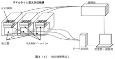
- a temperature control unit having a plurality of reaction wells and a detector for measuring the fluorescence intensity of the plurality of reaction wells, PCR is performed on a reaction vessel in which the temperature control unit is introduced. A cycle temperature adjustment is performed and the detector detects the analytical reaction over time.
- test sample erection unit 201 is a drawer and the user's access control is performed by a lock mechanism
- the flow and display unit shown in FIG. 5 and FIG. The screen to be displayed is explained.
- this embodiment is not limited to the drawer and the lock mechanism as long as the user can access control the inspection sample erection unit 201.
- the inspection sample erection unit 201 is an introduction slot, and access control is introduced.
- a partial shutter mechanism may be used, and the following details do not limit the present embodiment.
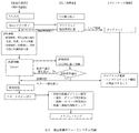
- FIG. 5 is a flowchart showing the relationship between user operations, the user interface 203 (UI), the calculation unit 205, and drawer lock control.
- the user interface 203 includes a check button, an order button, an inspection start button, and an inspection request screen (T / S input screen) for the inspection sample.
- the inspector inputs an inspection item from the request input screen of the user interface 203 before preparing the inspection sample, requests an inspection, and presses the check button after inputting the inspection item.
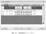
- the test item request input screen and check button as shown in FIG. 6A, at least a sample ID, a sample type, and a requested test item field and a check button are provided for each sample. More preferably, an information input field such as sample information and sample erection position information is provided.
- the control unit 207 locks the specimen sample erection unit, and the UI / calculation unit 205 confirms the expiration date at the time of erection of the apparatus for each test sample from the detailed information on the inspection item of the requested test sample. Then, the availability is confirmed from the number of samples in the measuring unit 206 under inspection, and a drawer lock release time at which a newly requested inspection sample can be installed is calculated and displayed on the user interface 203. Locking the inspection sample erection unit 201 prevents the user from accidentally laying the inspection sample on the inspection sample erection unit 201 at the timing when the expiration date of use expires during the measurement waiting time. Expiration can be prevented.
- the unlocking time of the test sample erection unit 201 displayed on the user interface 203 it is possible to display at least the time when the request (Order) that does not expire can be made, More preferably, a warning indicating that the inspector cannot be installed immediately and a time when the check is requested are displayed.
- the time display function is not limited to the present embodiment as long as the inspector can recognize any display method.
- the inspector prepares the inspection sample so that the inspection sample can be installed at the installation time after confirming the release time. More specifically, for example, if the release time is 30 minutes later and the time required for preparing the inspection sample is 10 minutes, the inspection sample can be prepared at the release time exactly by starting the inspection preparation after 20 minutes.
- the cancellation time display function allows the inspector to efficiently schedule the inspection and perform the inspection.
- the system can press the request button, and the user inputs all the information required for the inspection request and presses the request button. If there is an error in the input value of the request information, the system returns an error, and if there is no problem in the input value, the request information is registered in the system and the inspection sample erection unit 201 is unlocked.
- the check button character changes to a request (Order) button, and the request button can be pressed.
- the screen may have a request (Order) button, and when the release time comes, the request (Order) button may be pressed.
- the time display method of the user interface 203 only needs to be able to display the time, and the display method is not limited to this embodiment.
- the start deadline may be displayed on a pop-up screen. More preferably, as shown in FIG. 6 (d), after the inspection request button is pressed, the display of the inspection start (Start) button changes to display the time, thereby improving the efficiency of the button and improving the user visibility. Can be realized.
- this invention is not limited to the above-mentioned Example, Various modifications are included.
- the above-described embodiments have been described in detail for easy understanding of the present invention, and are not necessarily limited to those having all the configurations described.
- a part of the configuration of one embodiment can be replaced with the configuration of another embodiment, and the configuration of another embodiment can be added to the configuration of one embodiment.
- each of the above-described configurations, functions, processing units, processing means, and the like may be realized by hardware by designing a part or all of them with, for example, an integrated circuit.
- Each of the above-described configurations, functions, and the like may be realized by software by interpreting and executing a program that realizes each function by the processor.
- Information such as programs, tables, and files for realizing each function can be stored in a recording device such as a memory, a hard disk, an SSD (Solid State Drive), or a recording medium such as an IC card, an SD card, or a DVD.
- control lines and information lines indicate what is considered necessary for the explanation, and not all the control lines and information lines on the product are necessarily shown. Actually, it may be considered that almost all the components are connected to each other.
Landscapes
- Engineering & Computer Science (AREA)
- Quality & Reliability (AREA)
- Physics & Mathematics (AREA)
- Health & Medical Sciences (AREA)
- Life Sciences & Earth Sciences (AREA)
- Chemical & Material Sciences (AREA)
- Analytical Chemistry (AREA)
- Biochemistry (AREA)
- General Health & Medical Sciences (AREA)
- General Physics & Mathematics (AREA)
- Immunology (AREA)
- Pathology (AREA)
- Automatic Analysis And Handling Materials Therefor (AREA)
Abstract
装置上での架設時間に制限のある検査試料を装置上で運用した場合は、測定時間の長い検査が多数依頼されると検査待ちの状態となり、検査試料の使用期限が切れる可能性があった。当該課題に対して、依頼内容の入力情報から検査試料の架設時間を計算し、架設可能な時間を表示することで、検査試料を準備するタイミングを測ることができる。さらに、使用期限を守れる時間まで検査試料架設部201をロックし、検査依頼可能な時間に検査依頼のボタンを押下できるようにし、押下後に検査試料架設部201のロックを解除することで、ユーザが誤って使用期限を守れない検査試料を架設することを防ぐ。また、依頼時に検査開始期限を表示することで、検査者の開始ボタン押下遅れによる検査試料の使用期限切れを防止することができる。
Description
検査依頼された試料を自動サンプリングして分析する装置に関する。
生化学自動分析装置に代表される、生体試料を分析する自動分析装置の検査依頼から検査開始までの手順としては、1)検査依頼入力、2)依頼登録ボタン押下でユーザが検査試料を装置に架設する。多数の検査試料が検査依頼されて測定部が全て測定中の場合は、検査試料は検査待ち状態となる。測定部の測定完了後に測定待ちの検査試料の分析処理が開始され、検査試料容器からサンプリングされる。
ところで、検査に用いる試薬には有効期限があり、これに関連する背景技術として、例えば、特開2010-281845号公報がある。該公報には、「[課題]複数種類の試薬キットのそれぞれに対して、確実に試薬の有効期限の管理を行うこと。[解決手段]試薬ホルダーに保持された試薬キットから、その試薬キットが使用される測定項目および試薬キットの使用期限を含む識別情報を取得するとともに、その試薬キットの試薬開封後有効期限を設定し、識別情報に含まれる使用期限および設定された試薬開封後有効期限のうち早く期限の来る方を有効期限として、識別情報に含まれる測定項目とともに表示部に表示させる。」と記載されている(要約)。
遺伝子検査等の検査項目では、装置に架設している検査試料及び試薬に、装置架設後から検査試料及び試薬を分析に使用できるまでの使用期限が設定されている。検査試料及び試薬に装置架設後の使用期限がある場合は、従来運用では装置内で検査試料が分析待ち中に検査試料及び試薬の使用期限が切れる場合がある。具体的には、分析時間が3時間の検査項目を装置内において1度に測定することができる測定ポジション数以上依頼した後は、その後の依頼については分析待ちの時間が3時間近くとなり、例えば装置架設後使用期限が2時間の検査試料が依頼された場合では測定待ち時間中に使用期限が切れる。また、装置架設後のサンプリングまでの時間は架設前までに依頼されている検査項目次第のため、ユーザが事前に認識して装置架設タイミングを調節することは困難だった。さらに、検査試料を装置に架設した後にユーザが測定を開始するための検査開始依頼を実行し忘れた場合は、装置に架設したまま使用期限切れとなる問題があった。また、ユーザが架設した試料に対していつまでに検査開始依頼を実行すればよいかを判断することは困難だった。
そこで本発明は、上記課題の1つ以上を解決し、検査試料や試薬の使用期限に関するユーザの使い勝手が向上した自動分析装置を提供することを目的とする。
上記課題を解決するため、本発明は特許請求の範囲に記載の構成を採用する。具体的一例は、検査試料を測定する測定部と、測定部による測定の前に検査試料を架設し、測定部への導入を制御する検査試料架設部と、測定部による検査試料の測定が可能となるまでに要する時間と、検査試料の使用期限とを対比し、検査試料の使用期限の前に測定部による検査試料の測定が可能となるタイミングで、検査試料架設部への検査試料の架設を、ユーザへ許可し、あるいは、ユーザへ促すよう制御する制御部とを備える自動分析装置である。
本発明を実施することによって、検査試料や試薬の使用期限に関するユーザの使い勝手が向上する。例えば、検査者が検査試料を架設するタイミングが判るようになる。また、同時に検査試料の使用期限が切れるタイミングにおける検査試料の架設を防ぐことができる。また、検査者が検査試料架設後に使用期限を保証可能な検査開始までの時間を表示して、検査開始依頼忘れにより使用期限切れになることを防ぐことができる。
本実施例を実施するための1つの形態としての概要を図1に、システム構成の一例を図2に示す。本実施例では、少なくとも検査者による検査試料の導入を制御可能な検査試料架設部201と検査試料からサンプリング可能な分注機構202と検査の依頼が可能なユーザインターフェース203と依頼する検査項目の詳細情報を格納する記憶部204と測定タイミングを算出する演算部205および検査試料を分析する測定部206と、これらを統合制御する制御部207を備え、検査者がユーザインターフェース203から検査試料の依頼内容を入力してチェックボタンを押下することによって、装置が記憶部204に格納されている依頼された検査項目の詳細情報から各検査試料の架設時の使用期限を確認し、演算部205が検査中の測定部206の空き状況を確認して、新しく依頼された検査試料の架設可能なタイミングを計算して、依頼した検査試料の架設可能となる時間をユーザインターフェース203に表示する。さらに、チェックボタン押下と同時に検査者による検査試料架設部201への検査試料架設を防止し、依頼された検査試料が使用期限内に装置がサンプリング可能となるタイミングまで新規の検査試料架設を防止する。当該検査試料が使用期限内となるタイミングで依頼(Order)ボタンを押下可能とし、検査者が新規の依頼入力を全て終えて依頼ボタンを押した場合に、依頼入力内容に間違いがなければ新規の検査試料の架設を許可して試料架設部の架設防止を解除し、同時に検査予定の検査試料が使用期限切れとならないように測定できる検査開始依頼までの制限時間を表示する。検査者は新規の検査試料を装置に導入して制限時間以内に検査開始を依頼する。
本実施例は、装置架設後の使用期限を持つ検査試料に対して、装置上で使用期限切れとならないように運用するため様々な検討を行った結果、本実施例に至ったものである。
以下、本実施例本実施例を適用した図面を用いて本実施例本実施例を実現する装置構成および方法を詳細に説明するが、本実施例本実施例は、検査試料導入を制御可能な機構を備え、新規の検査試料の装置架設後の使用期限と検査中の測定部206の空き状況から検査者による検査試料の新規導入を制御可能であればよく、以下に記述する具体例に限定されない。
本実施例に必要とする最低限の機構と構成を図2に示す。図2に示すように、本実施例は検査者による検査試料の架設を制御可能な検査試料架設部201と検査試料からサンプリング可能な分注機構202と検査の依頼が可能なユーザインターフェース203または依頼を実行するボタンと依頼する検査項目の詳細情報を格納する記憶部204と依頼された検査試料の架設タイミングを算出する演算部205と、検査試料を測定する測定部206と、これらを統合制御する制御部207で構成される。
本実施例における検査試料架設部201とは、検査者が検査試料容器を架設可能な機構であり、検査者の検査試料架設を防止する機構または動作であればよく、本実施例に記載された検査試料架設部201の形状や検査で試料架設を防止する動作や機構が本実施例を制限するものではない。より具体的な例の一つとしては、図3(a)に示すように検査試料架設部201は引出し状の形状(以下、ドロワ)であり、ドロワ内の形状は検査試料容器を直接架設可能な形状でもよいし、検査試料ラックを架設可能な形状でもよい。また、検査者によるドロワ引出しを抑制するドロワをロックする機構を持つ。もう一つの具体的な例としては、図3(b)に示すように検査試料架設部201は円盤状で検査試料導入スロット機構を有し、検査試料導入スロットに検査試料ラックを置くと円盤状の検査試料架設部201に導入される。導入スロットに検査者による検査試料導入を抑制するシャッターを持ち、検査試料の導入を抑制する場合は、シャッターが閉じる。さらにもう一つの当該具体例としては、図3(c)に示すように検査試料架設部201は検査試料ラックを導入するレーンであり、レーンにラックを挿入することで検査試料ラックを導入できる構成であり、検査試料ラック導入レーン入口に検査試料の導入を抑制できる機構を有する。
本実施例における検査試料とは、装置架設後から検査に供されるまでの架設時間に制限のある試料であれば特に検査試料の種類、性状に限定されない。より具体的な例としては、RNA分解酵素により分解されやすいRNA試料、DNA分解酵素により分解されやすいDNA試料、分解されやすい蛋白質等が分析対象として含まれる血清、血漿、尿等が挙げられる。本実施例における検査試料ラックとは、上記の検査試料が入った検査試料容器を架設可能なラックであり、検査試料容器を複数架設できてもよい。
本実施例における分注機構202とは検査試料容器から検査試料をサンプリング可能であればいかなる構成でもよく、当該構成が本実施例を限定するものではない。より具体的な例としては、脱着式の分注チップを装着できるフィッティングと液体を吸引吐出可能なシリンジ機構を持ち、フィッティングが分注チップを装着後に、チップ先端を検査試料内に挿入しシリンジが吸引動作することにより試料を吸引できる。より好ましくは、分注チップは電気伝導性を持ち、静電容量方式による液面検知機能を持つ。
本実施例におけるユーザインターフェース203とは、少なくとも検査者が新規検査試料に対する検査依頼内容を入力できる機能、検査依頼内容を入力した新規検査試料に対して装置への架設タイミングを確認できる機能があればよく、より好ましくは新規検査試料を架設できるタイミングを時間表示できる機能、検査依頼を確定し、依頼確定後に検査開始までの時間表示ができる機能を有する。
本実施例において搭載する検査項目の詳細情報を格納する記憶部204とは、検査項目の詳細情報を記憶可能な記憶媒体であればいかなる構成でもよく、当該記憶媒体の種類が本実施例を制限するものではない。当該記憶部204には、検査項目毎に検査に必要な情報が格納される。少なくとも、検査項目に指定される試料の安定性時間(使用期限)情報と測定時間情報が格納される。当該記憶媒体は、演算部205とユーザインターフェース203が相互にアクセスでき、測定部206からの想定情報を記憶できる。
本実施例における演算部205とは主にCPUで構成されるが、本演算部205は依頼された検査項目の詳細情報から各検査試料の装置架設時の使用期限を確認し、さらに、検査中の測定部206の空き状況を確認して、新しく依頼された検査試料の架設可能なタイミングを計算できればよく演算部205の構成が本実施例を制限するものではない。より具体的には、当該演算部205は、記憶部204の検査項目のデータベースから依頼された検査項目の情報に基づいて、現在測定中および測定待ち状態の検査試料の処理時間および測定部206の測定時間から依頼された検査試料の処理開始時間を計算できる。そして、計算結果をユーザインターフェース203に返して、ユーザインターフェース203に表示することができる。
本実施例における測定部206はサンプリングされた検査試料と試薬の混合液を測定できればよく、測定部206の機構がいかなるものであれ本実施例を限定するものではない。より具体的な例の一つとしては、測定部206が回転型のリアルタイムPCR装置の場合は、図4(a)に示すように温調部と検出部から構成され、温調部が導入された反応容器に対してPCRサイクルの温度調節を実行し、回転盤が回転することによって検出部が検出部の前を通過した反応容器の蛍光色素を検出する。または、図4(b)に示すように複数の反応ウェルを持つ温調部と複数の反応ウェルの蛍光強度を測定する検出器から構成され、温調部が導入された反応容器に対してPCRサイクルの温度調節を実行し、検出器が分析反応を経時的に検出する。
当該構成、特に検査試料架設部201がドロワであり、ユーザのアクセス制御をロック機構で実施する構成の場合において、図5および図6を参酌して本実施例を実行するフローと表示部に示される画面を説明する。ただし、本実施例は検査試料架設部201のユーザによるアクセス制御が可能であればよく、ドロワおよびロック機構に限定するものではなく、例えば検査試料架設部201が導入スロットであり、アクセス制御が導入部シャッター機構でもよく、以下詳細が本実施例を限定するものではない。
図5はユーザ操作、ユーザインターフェース203(UI)および演算部205、ドロワのロック制御との関連およびフロー図である。本実施例においてユーザインターフェース203はチェックボタン、オーダーボタン、検査開始ボタンと検査試料に対する検査依頼画面(T/S入力画面)を備える。
検査依頼検査者は検査試料準備前にユーザインターフェース203の依頼入力画面より検査項目を入力し検査依頼を行い、検査項目入力後にチェックボタンを押下する。検査項目の依頼入力画面とチェックボタンの具体的な例としては、図6(a)に示すように、少なくとも検体毎に検体ID、検体種類、依頼検査項目を入力する欄とチェックボタンを備える。より好ましくは、検体情報、検体架設位置情報等の情報入力欄を備える。
チェックボタン押下後に制御部207が検体試料架設部をロックし、UI/演算部205は依頼された検査試料の検査項目の詳細情報から、各検査試料の装置架設時の使用期限を確認し、さらに、検査中の測定部206の試料数から空き状況を確認して、新しく依頼された検査試料の架設が可能となるドロワロック解除時刻を演算してユーザインターフェース203に表示する。検査試料架設部201をロックすることで、ユーザが誤って測定待ち時間中に使用期限が切れるタイミングで検査試料を検査試料架設部201に架設することを回避し、検査試料の装置架設時の使用期限切れを防止できる。
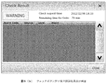
ユーザインターフェース203に表示する検査試料架設部201のロック解除時刻の具体的な例としては、図6(b)に示すように、少なくとも使用期限切れとならない依頼(Order)可能となる時刻を表示でき、より好ましくは、検査者に直ぐに架設できないことを意味する警告とチェックを依頼した時間が表示される。当該時刻表示機能はどのような表示方法であれ検査者が認識できればよく当該表示方法が本実施例を限定しない。
検査者は解除時刻を確認した後に架設可能時間に検査試料を架設できるように、検査試料を準備する。より具体的には、例えば解除時刻が30分後であり、検査試料を準備に要する時間が10分間であれば、20分後から検査準備を開始すれば解除時刻丁度に検査試料を準備できる。当該解除時刻表示機能により、検査者は検査を効率的にスケジュールして検査を実施できる。
ドロワのロック解除が可能な時刻にシステムは依頼ボタンが押下可能となり、ユーザは検査依頼に必要な情報を全て入力して依頼ボタンを押下する。システムは依頼情報の入力値に誤りがあればエラーを返し、入力値に問題がなければ依頼情報をシステムに登録して検査試料架設部201のロックを解除する。好ましい、具体的な依頼時の画面としては図6(c)に示すように、チェックボタンの文字が依頼(Order)ボタンに変化して依頼ボタンを押下可能となる。なお、画面にチェックボタンの他に依頼(Order)ボタンを持ち、解除時刻になったら当該依頼(Order)ボタンが押下可能となってもよい。
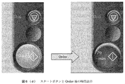
ロック解除と同時に使用期限切れとならない検査開始(Start)ボタン押下までの時刻(スタート期限)を表示し、検査者の検査開始ボタン押下遅れによる検査試料を架設後の使用期限切れを防止する。ユーザインターフェース203の時刻表示方法は時刻を表示できればよく当該表示方法は本実施例を限定するものではなく、例えばポップアップ画面によりスタート期限を表示してもよい。より好ましくは、図6(d)に示すように、検査依頼ボタン押下後に検査開始(Start)ボタンの表示が変化して時刻を表示することで、ボタンの効率化、ユーザ視認性の向上を効率的に実現できる。
なお、本発明は上記した実施例に限定されるものではなく、様々な変形例が含まれる。例えば、上記した実施例は本発明を分かりやすく説明するために詳細に説明したものであり、必ずしも説明した全ての構成を備えるものに限定されるものではない。また、ある実施例の構成の一部を他の実施例の構成に置き換えることが可能であり、また、ある実施例の構成に他の実施例の構成を加えることも可能である。また、各実施例の構成の一部について、他の構成の追加・削除・置換をすることが可能である。
また、上記の各構成、機能、処理部、処理手段等は、それらの一部又は全部を、例えば集積回路で設計する等によりハードウェアで実現してもよい。また、上記の各構成、機能等は、プロセッサがそれぞれの機能を実現するプログラムを解釈し、実行することによりソフトウェアで実現してもよい。各機能を実現するプログラム、テーブル、ファイル等の情報は、メモリや、ハードディスク、SSD(Solid State Drive)等の記録装置、または、ICカード、SDカード、DVD等の記録媒体に置くことができる。
また、制御線や情報線は説明上必要と考えられるものを示しており、製品上必ずしも全ての制御線や情報線を示しているとは限らない。実際には殆ど全ての構成が相互に接続されていると考えてもよい。
201・・検査試料架設部、202・・分注機構、203・・ユーザインターフェース、204・・記憶部、205・・演算部、206・・測定部、207・・制御部
Claims (5)
- 検査試料を測定する測定部と、
検査試料を架設し、前記測定部へ検査試料を導入する検査試料架設部と、
検査試料を測定に使用できる使用期限の情報を格納する記憶部と、
前記測定部へ検査試料の導入が可能となるまでの時間と、前記使用期限とを対比し、前記使用期限より前に前記測定部へ検査試料の導入が可能となるタイミングで、前記検査試料架設部へ前記検査試料の架設を、ユーザへ許可し、あるいは、ユーザへ促すよう制御するように構成されている制御部と、を備える自動分析装置。 - 請求項1において、
前記検査試料架設部への架設を防止する架設防止機構を備え、
前記制御部は、前記架設防止機構を制御して、前記検査試料架設部への前記検査試料の架設を、ユーザへ許可あるいは禁止するように構成されていること、
を特徴とする自動分析装置。 - 請求項1において、
前記使用期限より前に前記測定部へ検査試料の導入が可能となるタイミングの情報を表示する表示部を備え、
前記制御部は、前記使用期限より前に前記測定部へ検査試料の導入が可能となるタイミングの情報を前記表示部へ表示することによって、前記検査試料架設部への前記検査試料の架設を、ユーザへ促すこと、を特徴とする自動分析装置。 - 請求項1において、
前記測定部で測定する検査項目の入力が可能なユーザインターフェースを備え、
前記制御部は、前記測定部による前記検査試料の測定が可能となるまでに要する時間を演算すること、
を特徴とする自動分析装置。 - 請求項1において、
前記制御部は、前記検査試料の測定の前に行われている、あるいは行われる予定の測定に要する時間を演算し、前記測定部による前記検査試料の測定が可能となるまでに要する時間を演算すること、
を特徴とする自動分析装置。
Applications Claiming Priority (2)
| Application Number | Priority Date | Filing Date | Title |
|---|---|---|---|
| JP2013-030546 | 2013-02-20 | ||
| JP2013030546A JP2016106214A (ja) | 2013-02-20 | 2013-02-20 | 自動分析装置 |
Publications (1)
| Publication Number | Publication Date |
|---|---|
| WO2014129271A1 true WO2014129271A1 (ja) | 2014-08-28 |
Family
ID=51391067
Family Applications (1)
| Application Number | Title | Priority Date | Filing Date |
|---|---|---|---|
| PCT/JP2014/051878 Ceased WO2014129271A1 (ja) | 2013-02-20 | 2014-01-29 | 自動分析装置 |
Country Status (2)
| Country | Link |
|---|---|
| JP (1) | JP2016106214A (ja) |
| WO (1) | WO2014129271A1 (ja) |
Families Citing this family (1)
| Publication number | Priority date | Publication date | Assignee | Title |
|---|---|---|---|---|
| JP7491477B2 (ja) * | 2021-07-29 | 2024-05-28 | 株式会社島津製作所 | 分析システム、分析装置および制御方法 |
Citations (2)
| Publication number | Priority date | Publication date | Assignee | Title |
|---|---|---|---|---|
| JPH1031025A (ja) * | 1996-07-16 | 1998-02-03 | Tosoh Corp | 生化学分析装置 |
| JP2008039556A (ja) * | 2006-08-04 | 2008-02-21 | Canon Inc | 検体処理装置および検体処理方法 |
-
2013
- 2013-02-20 JP JP2013030546A patent/JP2016106214A/ja active Pending
-
2014
- 2014-01-29 WO PCT/JP2014/051878 patent/WO2014129271A1/ja not_active Ceased
Patent Citations (2)
| Publication number | Priority date | Publication date | Assignee | Title |
|---|---|---|---|---|
| JPH1031025A (ja) * | 1996-07-16 | 1998-02-03 | Tosoh Corp | 生化学分析装置 |
| JP2008039556A (ja) * | 2006-08-04 | 2008-02-21 | Canon Inc | 検体処理装置および検体処理方法 |
Also Published As
| Publication number | Publication date |
|---|---|
| JP2016106214A (ja) | 2016-06-16 |
Similar Documents
| Publication | Publication Date | Title |
|---|---|---|
| US10416177B2 (en) | Analysis system for a biological sample | |
| CN101275966B (zh) | 自动分析装置 | |
| EP3088901B1 (en) | Automatic analysis device and analysis method | |
| CN102305868B (zh) | 自动分析装置 | |
| EP3415920B1 (en) | Automatic analysis device | |
| CN101666807B (zh) | 自动分析装置 | |
| WO2013103119A1 (ja) | 自動分析装置および自動分析装置における試薬処理方法 | |
| JP6788745B2 (ja) | 自動分析装置 | |
| US20110208536A1 (en) | Clinical test information managing apparatus and non-transitory storage medium | |
| CN108027378A (zh) | 自动分析装置 | |
| EP2690443A1 (en) | Specimen analysis device, specimen information processing device, and specimen analysis method | |
| JP2013156256A (ja) | 加熱されたピペット針部内の一定体積の液体を加熱する方法 | |
| JP2012108010A (ja) | 自動分析装置 | |
| CN103293329B (zh) | 自动分析装置 | |
| CN112782413B (zh) | 一种体外诊断分析仪及其质控处理方法 | |
| JP6419641B2 (ja) | 自動分析装置及び多重測定方法 | |
| JP2016106214A (ja) | 自動分析装置 | |
| EP4202442B1 (en) | Specimen analysis method and specimen analyzer | |
| JP4491505B2 (ja) | 自動分析装置 | |
| EP3660514A1 (en) | Automated analyzer and image processing method | |
| CN117795345A (zh) | 自动分析装置和自动分析系统 | |
| JP6381773B2 (ja) | コントロール運用方法、および自動分析装置 | |
| EP3640647A1 (en) | Automated analysis device | |
| WO2023007936A1 (ja) | 自動分析装置及び試薬管理方法 | |
| CN112611878A (zh) | 自动取样器的控制装置及自动测定系统 |
Legal Events
| Date | Code | Title | Description |
|---|---|---|---|
| 121 | Ep: the epo has been informed by wipo that ep was designated in this application |
Ref document number: 14754808 Country of ref document: EP Kind code of ref document: A1 |
|
| NENP | Non-entry into the national phase |
Ref country code: DE |
|
| 122 | Ep: pct application non-entry in european phase |
Ref document number: 14754808 Country of ref document: EP Kind code of ref document: A1 |
|
| NENP | Non-entry into the national phase |
Ref country code: JP |