WO2014129228A1 - 予備凍結装置 - Google Patents
予備凍結装置 Download PDFInfo
- Publication number
- WO2014129228A1 WO2014129228A1 PCT/JP2014/050313 JP2014050313W WO2014129228A1 WO 2014129228 A1 WO2014129228 A1 WO 2014129228A1 JP 2014050313 W JP2014050313 W JP 2014050313W WO 2014129228 A1 WO2014129228 A1 WO 2014129228A1
- Authority
- WO
- WIPO (PCT)
- Prior art keywords
- temperature
- sample
- sample mounting
- low
- mounting member
- Prior art date
- Legal status (The legal status is an assumption and is not a legal conclusion. Google has not performed a legal analysis and makes no representation as to the accuracy of the status listed.)
- Ceased
Links
Images

Classifications
-
- A—HUMAN NECESSITIES
- A01—AGRICULTURE; FORESTRY; ANIMAL HUSBANDRY; HUNTING; TRAPPING; FISHING
- A01N—PRESERVATION OF BODIES OF HUMANS OR ANIMALS OR PLANTS OR PARTS THEREOF; BIOCIDES, e.g. AS DISINFECTANTS, AS PESTICIDES OR AS HERBICIDES; PEST REPELLANTS OR ATTRACTANTS; PLANT GROWTH REGULATORS
- A01N1/00—Preservation of bodies of humans or animals, or parts thereof
- A01N1/10—Preservation of living parts
- A01N1/14—Mechanical aspects of preservation; Apparatus or containers therefor
- A01N1/146—Non-refrigerated containers specially adapted for transporting or storing living parts whilst preserving
- A01N1/147—Carriers for immersion in cryogenic fluid for slow freezing or vitrification
-
- A—HUMAN NECESSITIES
- A01—AGRICULTURE; FORESTRY; ANIMAL HUSBANDRY; HUNTING; TRAPPING; FISHING
- A01N—PRESERVATION OF BODIES OF HUMANS OR ANIMALS OR PLANTS OR PARTS THEREOF; BIOCIDES, e.g. AS DISINFECTANTS, AS PESTICIDES OR AS HERBICIDES; PEST REPELLANTS OR ATTRACTANTS; PLANT GROWTH REGULATORS
- A01N1/00—Preservation of bodies of humans or animals, or parts thereof
- A01N1/10—Preservation of living parts
- A01N1/14—Mechanical aspects of preservation; Apparatus or containers therefor
- A01N1/142—Apparatus
- A01N1/144—Apparatus for temperature control, e.g. refrigerators or freeze-drying apparatus
- A01N1/145—Stationary or portable vessels generating cryogenic temperatures, e.g. liquid nitrogen baths
Definitions
- the present invention relates to a preliminary freezing apparatus, and more particularly to a preliminary freezing apparatus for cooling a sample formed in a sheet shape from a normal temperature to a temperature near a cryopreservation temperature with a low-temperature liquefied gas.
- a slow freezing method is known as a pretreatment when a biological sample is stored frozen.
- a biological sample for cryopreservation is sealed in a container such as an ampoule at room temperature, and then slowly cooled to an appropriate temperature between room temperature and cryopreservation temperature, and pre-frozen.
- a cryopreservation container in which cryogenic liquid nitrogen is stored for example, see Patent Document 1.
- the conventional apparatus used for the slow freezing method is effective for the case where a biological sample for cryopreservation is enclosed in a container such as an ampoule, but preliminarily freezes the biological sample for cryopreservation formed in a sheet shape. I could't.
- an object of the present invention is to provide a pre-freezing apparatus that can reliably pre-freeze a sample formed in a sheet shape.
- the preliminary freezing apparatus of the present invention is a preliminary freezing apparatus for prefreezing a biological sample for cryopreservation formed in a sheet form in a gas phase in a low temperature liquefied gas container containing a low temperature liquefied gas.
- a freezing apparatus, a sample mounting member having a sample mounting portion for mounting the cryopreservation biological sample formed in the sheet shape, and the sample mounting member in a gas phase in the low-temperature liquefied gas container A holding member that is held inside, and a heat conduction member that protrudes below the sample mounting member and is inserted into the low-temperature liquefied gas in the low-temperature liquefied gas container.
- the sample mounting portion is formed of a member having air permeability, and a temperature at which the temperature of the sample mounting member or the ambient temperature of the sample mounting member is measured.
- a sensor in addition to electric elevating means for elevating and lowering the sample mounting member in the low temperature liquefied gas container, and when the sample mounting member is lowered into the low temperature liquefied gas container
- the electric lifting / lowering means is operated in a direction to lower the sample mounting member, and when the measured temperature is lower than the cooling temperature range, the sample mounting is performed. It has a control part which operates the electric lifting means in the direction which raises the member.
- a cryogenic gas for cryopreservation formed in a sheet shape is placed on the sample placement portion of the sample placement member, and the sample placement member is cooled with a low-temperature liquefied gas.
- the biological sample directly into the low-temperature liquefied gas by inserting it into the housed low-temperature liquefied gas container, holding the sample mounting member in the gas phase, and inserting the heat conducting member into the liquid phase.
- the cold heat of the low-temperature liquefied gas can be transmitted from the heat conduction member to the biological sample for cryopreservation via the sample mounting member, the biological sample for cryopreservation formed in a sheet shape is kept in a sheet shape.
- the low-temperature liquefied gas does not excessively boil and damage the sheet-like biological sample for cryopreservation. Loss can be suppressed and adverse effects on the surrounding environment can also be suppressed.
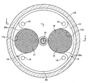
- FIG. 3 is a sectional view taken along the line II in FIG. 2. It is a top view which shows one example of the preliminary freezing apparatus of this invention.
- the preliminary freezing apparatus shown in the present embodiment has two sample placement portions 11 for placing two biological samples for cryopreservation (hereinafter sometimes referred to as sheet-like samples) formed in a sheet shape.
- a heat conduction member 15 that protrudes below the mounting member 12 and is inserted into the low-temperature liquefied gas inside the low-temperature liquefied gas container 13, and a temperature sensor 16 that measures the temperature of the sample mounting member 12.
- the sample mounting member 12 is provided between two disk-shaped members 17 made of a thin metal plate such as aluminum, copper, and stainless steel having good thermal conductivity and excellent corrosion resistance. It is formed by a member having air permeability, for example, a net-like member 18.
- the two disk-shaped members 17 are respectively formed with circular openings 17a having an inner diameter larger than the outer diameter of the sheet-like sample accommodated in the bag or tray at positions facing each other across the center.
- the upper surface portion of the mesh member 18 located on the inner periphery of the sample is the sample mounting portion 11.
- the holding member 14 has four rod-shaped connecting members 19 projecting upward from a position avoiding the opening 17a at the outer peripheral portion of the sample mounting member 12, and an upper end portion of the connecting member 19 are fixed to each other.
- the holding plate 20 and a cylindrical suspension member 21 protruding upward from the central portion of the holding plate 20 are formed.
- the holding plate 20 is provided with a notch 20a in a portion positioned above the sample mounting portion 11 so that the sheet-like sample can be easily handled.
- the temperature sensor 16 is inserted inside.
- the temperature sensor 16 is arranged so as to measure the temperature around the sheet-like sample placed on the sample placement unit 11 at a position in contact with or close to the upper surface of the sample placement member 12.
- the temperature sensor 16 is preferably a sheathed thermocouple with good response.
- the heat conduction member 15 is formed of a metal rod-like member such as aluminum, copper, and stainless steel having good heat conductivity and excellent corrosion resistance, like the disk-like member 17.
- a small diameter shaft portion provided at the lower end of the connecting member 19 is formed with a male screw 19 a and a female screw 15 a is formed at the upper end of the heat conducting member 15 to form a small hole formed in the disk-shaped member 17.
- the sample mounting member 12 By sandwiching the portion between the connecting member 19 and the heat conducting member 15, the sample mounting member 12 can be held in a stable state.
- the length of the heat conducting member 15 is arbitrary, but when the tip of the heat conducting member 15 is inserted into the low-temperature liquefied gas, the gas is generated from the boiled low-temperature liquefied gas to the sample mounting portion 11. The length should be set so that the placed sheet sample is not physically adversely affected.
- the mesh member 18 promotes cooling of the sheet-like sample by the low-temperature gas passing through the mesh member 18 and the cold heat of the mesh member 18 cooled from the heat conducting member 15 via the disk-like member 17.
- a wire net made of aluminum, copper, stainless steel, or the like that has strength that allows the sheet-like sample housed in a bag or tray to be placed in a low-temperature atmosphere and that has good thermal conductivity.
- the mesh member 18 may be formed of a synthetic resin such as a fluororesin or polypropylene. As long as the size of the net-like member 18 is larger than the opening 17 a and smaller than the disc-like member 17, it can have any size and shape. Further, the net-like member 18 and the disk-like member 17 can be fixed with an adhesive or the like.
- the sheet-like sample is placed on the mesh member 18 of the sample placement unit 11 at room temperature.
- the sample mounting member 12 is placed inside the low-temperature liquefied gas container 13 storing the low-temperature liquefied gas L in a state where the sample mounting member 12 is suspended by the cylindrical suspension member 21 of the holding member 14.
- the lower end of the heat conducting member 15 is inserted into the low-temperature liquefied gas.
- the temperature measured by the temperature sensor 16 is appropriately checked, and the vertical position of the sample mounting member 12 is finely adjusted so that the measured temperature is within the preset pre-freezing cooling temperature range.
- the sheet-like sample is gently cooled at a predetermined cooling rate, for example, about ⁇ 1 ° C. per minute, or rapidly cooled at a relatively high cooling rate. You can do it.
- the sheet-like sample is held in the gas phase, so the sheet-like sample is not physically damaged by boiling of the low-temperature liquefied gas.
- a sample in which the cultured cells are formed into a sheet shape can be surely pre-frozen and stored frozen while keeping the sheet shape.
- the heat conducting member 15 for inserting the lower end portion into the low temperature liquefied gas in the low temperature liquefied gas container 13 is provided, the sample mounting member 12 holding the sheet-like sample can be effectively cooled, By appropriately setting the position and the number of the heat conducting members 15 in the sample mounting member 12, the entire sheet-like sample placed on the sample placing unit 11 is uniformly cooled and kept at a predetermined low temperature state. Can do. Thereby, a part of the sheet-like sample is rapidly cooled to cause partial contraction, and the partial contraction does not damage the sheet-like sample.
- the sample mounting member 12 After holding in the cooling temperature range for a preset time, the sample mounting member 12 is raised, the pre-frozen sheet sample is taken out from the sample mounting unit 11, and transferred into a predetermined cryopreservation container. As a result, the sheet-like sample can be frozen and stored.
- the elevating / lowering of the sample mounting member 12 into the cryogenic liquefied gas container 13 can be performed by connecting the cylindrical suspension member 21 to the elevating part of an appropriate electric elevating means.
- the lowering switch of the electric lifting means When the sample mounting member 12 is moved up and down manually, for example, the lowering switch of the electric lifting means is turned on, the motor of the electric lifting means is rotated in the lowering direction, and the temperature of the temperature sensor 16 is lowered while lowering the sample mounting member 12.
- the vertical position of the mounting member 12 may be finely adjusted.
- the temperature signal of the temperature sensor 16 is taken into the control unit provided in the electric lifting means, and the measured temperature of the temperature sensor 16 is determined to be higher than the cooling temperature range. May be set to rotate the motor of the electric lifting means in the downward direction and rotate the motor in the upward direction when it is determined that the measured temperature is lower than the cooling temperature range.
- the preliminary freezing apparatus having such a structure can be manufactured in large quantities from a small research apparatus that handles a small number of sheet-like samples by appropriately forming the sample mounting member 12 according to the size of the sheet-like sample and the number of processed sheets. It is possible to apply even to a large-sized apparatus that handles the sheet-like sample.
- the shape of the sample mounting member and the sample mounting portion is not limited to a circular shape, and can be formed in a square shape in accordance with the shape of the sheet-like sample, and the sample mounting provided on one sample mounting member
- the number of parts is also arbitrary.
- a punching plate perforated plate
- a cloth can be used depending on the state of the sheet-like sample.
- the entire sample mounting member including the sample mounting portion can be formed by a punching plate, the shape of the heat conducting member is arbitrary, and the structure of the holding member is also arbitrary.
- the sample mounting member is placed at a predetermined position by visually confirming the amount of heat conduction member inserted into the low temperature liquefied gas from the outside without providing a temperature sensor. It is also possible to carry out preliminary freezing in this state.
- a temperature sensor can be provided at an appropriate position in the low-temperature liquefied gas container, and the position of the sample mounting member can be adjusted by comparing the position of the temperature sensor with the position of the sample mounting member.
Landscapes
- Life Sciences & Earth Sciences (AREA)
- Health & Medical Sciences (AREA)
- Engineering & Computer Science (AREA)
- Dentistry (AREA)
- General Health & Medical Sciences (AREA)
- Wood Science & Technology (AREA)
- Zoology (AREA)
- Environmental Sciences (AREA)
- Sampling And Sample Adjustment (AREA)
- Medical Preparation Storing Or Oral Administration Devices (AREA)
Abstract
シート状に形成された凍結保存用生体試料を、シート状の形状を保ったまま予備凍結させることができる予備凍結装置であって、シート状に形成された凍結保存用生体試料を載置する試料載置部11を備えた試料載置部材12と、該試料載置部材を低温液化ガス容器13内の気相中に保持する保持部材14と、試料載置部材の下方に突出して低温液化ガス容器内の低温液化ガス中に挿入される熱伝導部材15とを備えている。シート状に形成された凍結保存用生体試料は、試料載置部材12に載置された状態で、低温液化ガスに直接接触することなく、低温のガスにより冷却されて予備凍結される。
Description
本発明は、予備凍結装置に関し、詳しくは、シート状に形成された試料を低温液化ガスによって常温から凍結保存温度付近まで冷却するための予備凍結装置に関する。
一般的に、生体試料を凍結保存する際の前処理として緩慢凍結法が知られている。この緩慢凍結法では、常温でアンプルなどの容器に凍結保存用生体試料を封入した後、常温と凍結保存温度との間の適当な温度までゆっくりと冷却して予備凍結させ、予備凍結後の容器を極低温の液体窒素を貯留した凍結保存容器内に収容して凍結保存するようにしている(例えば、特許文献1参照。)。
しかし、従来の緩慢凍結法に用いる装置では、アンプルなどの容器に凍結保存用生体試料を封入したものに対しては有効であるが、シート状に形成された凍結保存用生体試料を予備凍結することができなかった。
そこで本発明は、シート状に形成された試料を確実に予備凍結させることができる予備凍結装置を提供することを目的としている。
上記目的を達成するため、本発明の予備凍結装置は、低温液化ガスを収容した低温液化ガス容器内の気相中で、シート状に形成された凍結保存用生体試料を予備凍結させるための予備凍結装置であって、前記シート状に形成された凍結保存用生体試料を載置する試料載置部を備えた試料載置部材と、該試料載置部材を前記低温液化ガス容器内の気相中に保持する保持部材と、前記試料載置部材の下方に突出して前記低温液化ガス容器内の前記低温液化ガス中に挿入される熱伝導部材とを備えていることを特徴としている。
さらに、本発明の予備凍結装置は、前記試料載置部が通気性を有する部材により形成されていること、また、前記試料載置部材の温度あるいは前記試料載置部材の周辺温度を測定する温度センサを備えていること、加えて、前記低温液化ガス容器内に前記試料載置部材を昇降させる電動昇降手段を備えるとともに、前記試料載置部材を前記低温液化ガス容器内に下降させたときに、前記温度センサの測定温度があらかじめ設定された冷却温度範囲より高いときには前記試料載置部材を下降させる方向に前記電動昇降手段を作動させ、測定温度が前記冷却温度範囲より低いときには前記試料載置部材を上昇させる方向に前記電動昇降手段を作動させる制御部を備えていることを特徴としている。
本発明の予備凍結装置によれば、シート状に形成された凍結保存用生体試料を試料載置部材の試料載置部に載置した状態で、保持部材によって試料載置部材を低温液化ガスを収容した低温液化ガス容器内に挿入し、試料載置部材を気相中に保持するとともに、熱伝導部材を液相中に挿入することにより、生体試料を低温液化ガスに直接接触させることなく、かつ、低温液化ガスの冷熱を熱伝導部材から試料載置部材を介して凍結保存用生体試料に伝達することができるので、シート状に形成された凍結保存用生体試料を、シート状に保ったまま確実に予備凍結することができる。また、熱伝導部材の液相中への挿入量を適切に設定することにより、低温液化ガスが過剰に沸騰してシート状の凍結保存用生体試料に損傷を与えることもなく、低温液化ガスの損失を抑えられるとともに、周辺環境への悪影響も抑えることができる。
本形態例に示す予備凍結装置は、シート状に形成された2枚の凍結保存用生体試料(以下、シート状試料と記載するときがある。)を載置する試料載置部11を2箇所備えた試料載置部材12と、シート状試料を試料載置部11に載置した試料載置部材12を低温液化ガス容器13の内部の気相中に保持するための保持部材14と、試料載置部材12の下方に突出して低温液化ガス容器13の内部の低温液化ガス中に挿入される熱伝導部材15とを備えるとともに、試料載置部材12の温度を測定する温度センサ16を備えている。
試料載置部材12は、熱伝導性が良好で耐食性にも優れたアルミニウム、銅、ステンレス鋼などの金属製薄板からなる2枚の円盤状部材17と、2枚の円盤状部材17の間に挟持される通気性を有する部材、例えば、網状部材18とで形成されている。2枚の円盤状部材17には、中心を挟んで対向する位置に、バッグやトレイに収容したシート状試料の外径より大きな内径を有する円形の開口部17aがそれぞれ形成され、該開口部17aの内周に位置する網状部材18の上面部分が前記試料載置部11となっている。
保持部材14は、前記試料載置部材12の外周部で、前記開口部17aを避けた位置から上方に突出した4本の棒状の連結部材19と、該連結部材19の上端部がそれぞれ固着された保持板20と、該保持板20の中央部から上方に突出した筒状吊持部材21とで形成されている。前記保持板20は、前記試料載置部11の上方に位置する部分に、シート状試料の取り扱いを容易に行えるようにするための切欠部20aが設けられており、筒状吊持部材21の内部には、前記温度センサ16が挿通されている。この温度センサ16は、試料載置部材12の上面に当接する位置あるいは近接した位置で、試料載置部11に載置されたシート状試料の周囲の温度を測定できるように配置されている。この温度センサ16には、応答性が良好なシース熱電対を使用することが好ましい。
熱伝導部材15は、前記円盤状部材17と同様に、熱伝導性が良好で耐食性にも優れたアルミニウム、銅、ステンレス鋼などの金属製棒状部材で形成されている。本形態例では、前記連結部材19の下端に設けた小径軸部に雄ネジ19aを形成するとともに、熱伝導部材15の上端に雌ネジ15aを形成し、円盤状部材17に形成した小通孔17bに挿通した小径軸部の雄ネジ19aと雌ネジ15aとを螺着することにより、熱伝導部材15を試料載置部材12の下面に固着するとともに、試料載置部材12の外周部分の4箇所を連結部材19と熱伝導部材15とによって挟み込むことにより、試料載置部材12を安定した状態で保持できるようにしている。この熱伝導部材15の長さは任意であるが、熱伝導部材15の先端部を低温液化ガス中に挿入したときに、沸騰した低温液化ガスから発生するガスの噴出によって試料載置部11に載置したシート状試料が物理的な悪影響を受けない長さに設定すべきである。
網状部材18は、該網状部材18を通過する低温のガスと、前記熱伝導部材15から円盤状部材17を介して冷却された網状部材18の冷熱とによってシート状試料の冷却を促進するものであって、バッグやトレイに収容したシート状試料を低温雰囲気中で載置できる強度を有するとともに、熱伝導性が良好なアルミニウム、銅、ステンレス鋼などからなる金網を使用することが好ましい。また、シート状試料を収容したバッグやトレイが網状部材18に張り付くおそれがある場合は、フッ素樹脂やポリプロピレンなどの合成樹脂で網状部材18を形成することもできる。網状部材18の大きさは、開口部17aより大きく、円盤状部材17より小さければ、任意の大きさ及び形状とすることができる。また、網状部材18と円盤状部材17とを接着剤などで固着しておくこともできる。
このように形成した予備凍結装置を使用して、シート状に形成された凍結保存用生体試料を予備凍結する際には、まず、常温でシート状試料を試料載置部11の網状部材18上に載置した後、保持部材14の筒状吊持部材21で試料載置部材12を吊持した状態で、低温液化ガスLを貯留した低温液化ガス容器13の内部に試料載置部材12をゆっくりと下降させ、熱伝導部材15の下端部を低温液化ガス中に挿入した状態とする。この予備凍結中の状態で、温度センサ16の測定温度を適宜確認し、測定温度があらかじめ設定された予備凍結用の冷却温度範囲内に収まるように試料載置部材12の上下方向位置を微調整する。これにより、低温液化ガス容器13内の気相中で、シート状試料を、所定の冷却速度、例えば毎分-1℃程度の速度で緩やかに冷却したり、比較的高い冷却速度で急速に冷却したりすることができる。
予備凍結中は、シート状試料を気相中に保持しているので、低温液化ガスの沸騰などでシート状試料が物理的な損傷を受けることはなく、例えば、再生医療などに使用するために培養した細胞をシート状に形成した試料をシート状を保った状態で確実に予備凍結して凍結保存することが可能となる。また、低温液化ガス容器13内の低温液化ガス中に下端部を挿入する熱伝導部材15を備えているので、シート状試料を保持した試料載置部材12を効果的に冷却することができ、試料載置部材12における熱伝導部材15の位置や設置数を適切に設定することにより、試料載置部11に載置したシート状試料の全体を均一に冷却して所定の低温状態に保つことができる。これにより、シート状試料の一部が急速に冷却されて部分的な収縮が発生し、この部分的な収縮によってシート状試料が破損することもなくなる。
前記冷却温度範囲での保持を、あらかじめ設定された時間行った後、試料載置部材12を上昇させて試料載置部11から予備凍結したシート状試料を取り出し、所定の凍結保存容器内に移すことにより、シート状試料の凍結保存を行うことができる。
低温液化ガス容器13内への試料載置部材12の昇降は、適宜な電動昇降手段の昇降部に筒状吊持部材21を連結することによって行うことができる。手動で試料載置部材12を昇降させる場合、例えば、電動昇降手段の下降用スイッチをオンにして電動昇降手段のモータを下降方向に回転させ、試料載置部材12を下降させながら温度センサ16の測定温度を確認し、測定温度が前記冷却温度範囲内になった位置で下降用スイッチをオフとし、温度センサ16の測定温度の変動に応じて下降用又は上昇用スイッチを操作することにより、試料載置部材12の上下方向位置を微調整すればよい。
一方、自動で試料載置部材12を昇降させる場合は、温度センサ16の温度信号を電動昇降手段に設けた制御部に取り込み、温度センサ16の測定温度が前記冷却温度範囲より高いと判断したときは、電動昇降手段のモータを下降方向に回転させ、測定温度が冷却温度範囲より低いと判断したときはモータを上昇方向に回転させるように設定すればよい。
このような構造を有する予備凍結装置は、シート状試料の大きさや処理枚数に応じて試料載置部材12を適切に形成することにより、少数のシート状試料を扱う研究用の小型装置から、大量のシート状試料を扱う大型装置にまで適用することが可能である。
なお、試料載置部材や試料載置部の形状は円形に限るものではなく、シート状試料の形状に合わせて角形に形成することも可能であり、一つの試料載置部材に設ける試料載置部の数も任意である。また、試料載置部には、パンチングプレート(多孔板)を使用することもでき、シート状試料の状態によっては、布を用いることも可能である。さらに、試料載置部を含む試料載置部材の全体をパンチングプレートで形成することもでき、熱伝導部材の形状も任意であり、保持部材の構造も任意である。
また、低温液化ガス容器として透明ガラス製デュワー瓶を使用した場合は、温度センサを設けずに、低温液化ガス中への熱伝導部材の挿入量を外部から視認して試料載置部材を所定位置に保持し、この状態で予備凍結を行うことも可能である。さらに、温度センサを低温液化ガス容器内の適宜な位置に設け、温度センサの位置と試料載置部材の位置とを比較して試料載置部材の保持位置を調節することも可能である。
11…試料載置部、12…試料載置部材、13…低温液化ガス容器、14…保持部材、15…熱伝導部材、15a…雌ネジ、16…温度センサ、17…円盤状部材、17a…開口部、17b…小通孔、18…網状部材、19…連結部材、19a…雄ネジ、20…保持板、20a…切欠部、21…筒状吊持部材
Claims (4)
- 低温液化ガスを収容した低温液化ガス容器内の気相中で、シート状に形成された凍結保存用生体試料を予備凍結させるための予備凍結装置であって、前記シート状に形成された凍結保存用生体試料を載置する試料載置部を備えた試料載置部材と、該試料載置部材を前記低温液化ガス容器内の気相中に保持する保持部材と、前記試料載置部材の下方に突出して前記低温液化ガス容器内の前記低温液化ガス中に挿入される熱伝導部材とを備えている予備凍結装置。
- 前記試料載置部は、通気性を有する部材により形成されている請求項1記載の予備凍結装置。
- 前記試料載置部材の温度あるいは前記試料載置部材の周辺温度を測定する温度センサを備えている請求項1又は2記載の予備凍結装置。
- 前記低温液化ガス容器内に前記試料載置部材を昇降させる電動昇降手段を備えるとともに、前記試料載置部材を前記低温液化ガス容器内に下降させたときに、前記温度センサの測定温度があらかじめ設定された冷却温度範囲より高いときには前記試料載置部材を下降させる方向に前記電動昇降手段を作動させ、測定温度が前記冷却温度範囲より低いときには前記試料載置部材を上昇させる方向に前記電動昇降手段を作動させる制御部を備えている請求項3記載の予備凍結装置。
Applications Claiming Priority (2)
| Application Number | Priority Date | Filing Date | Title |
|---|---|---|---|
| JP2013-030751 | 2013-02-20 | ||
| JP2013030751A JP6148032B2 (ja) | 2013-02-20 | 2013-02-20 | 予備凍結装置 |
Publications (1)
| Publication Number | Publication Date |
|---|---|
| WO2014129228A1 true WO2014129228A1 (ja) | 2014-08-28 |
Family
ID=51391024
Family Applications (1)
| Application Number | Title | Priority Date | Filing Date |
|---|---|---|---|
| PCT/JP2014/050313 Ceased WO2014129228A1 (ja) | 2013-02-20 | 2014-01-10 | 予備凍結装置 |
Country Status (2)
| Country | Link |
|---|---|
| JP (1) | JP6148032B2 (ja) |
| WO (1) | WO2014129228A1 (ja) |
Families Citing this family (1)
| Publication number | Priority date | Publication date | Assignee | Title |
|---|---|---|---|---|
| JP6689583B2 (ja) * | 2015-07-31 | 2020-04-28 | 大陽日酸株式会社 | シート状生体試料の収納具、収納ラック及び収納棚 |
Citations (3)
| Publication number | Priority date | Publication date | Assignee | Title |
|---|---|---|---|---|
| JPH09110601A (ja) * | 1996-09-05 | 1997-04-28 | Biosurface Technol Inc | 培養上皮細胞シートの凍結保存 |
| JP2005143873A (ja) * | 2003-11-17 | 2005-06-09 | Taiyo Nippon Sanso Corp | 凍結保存容器 |
| JP2008005846A (ja) * | 1995-06-07 | 2008-01-17 | Phyton Inc | 多様な植物細胞の凍結保存方法 |
Family Cites Families (4)
| Publication number | Priority date | Publication date | Assignee | Title |
|---|---|---|---|---|
| JPS6135945Y2 (ja) * | 1980-10-25 | 1986-10-18 | ||
| US4388814A (en) * | 1982-03-26 | 1983-06-21 | Schilling Dean W | Cryogenic device and method |
| JPH03221770A (ja) * | 1990-01-29 | 1991-09-30 | Matsushita Electric Ind Co Ltd | 冷却装置 |
| JP3356636B2 (ja) * | 1996-11-08 | 2002-12-16 | 株式会社日立製作所 | 急速凍結装置 |
-
2013
- 2013-02-20 JP JP2013030751A patent/JP6148032B2/ja active Active
-
2014
- 2014-01-10 WO PCT/JP2014/050313 patent/WO2014129228A1/ja not_active Ceased
Patent Citations (3)
| Publication number | Priority date | Publication date | Assignee | Title |
|---|---|---|---|---|
| JP2008005846A (ja) * | 1995-06-07 | 2008-01-17 | Phyton Inc | 多様な植物細胞の凍結保存方法 |
| JPH09110601A (ja) * | 1996-09-05 | 1997-04-28 | Biosurface Technol Inc | 培養上皮細胞シートの凍結保存 |
| JP2005143873A (ja) * | 2003-11-17 | 2005-06-09 | Taiyo Nippon Sanso Corp | 凍結保存容器 |
Also Published As
| Publication number | Publication date |
|---|---|
| JP6148032B2 (ja) | 2017-06-14 |
| JP2014158596A (ja) | 2014-09-04 |
Similar Documents
| Publication | Publication Date | Title |
|---|---|---|
| US4473739A (en) | Process and apparatus for warming of suspensions or solutions frozen in a flat plastic bag | |
| US4388814A (en) | Cryogenic device and method | |
| CN106455862A (zh) | 用于自动样品解冻的系统、装置和方法 | |
| CN111565850A (zh) | 用于自动化解冻袋状存储容器的系统,设备和方法 | |
| JP5852499B2 (ja) | 生体試料の予備凍結装置 | |
| EP3011290B1 (en) | Bioreactor system comprising a temperature sensor means | |
| US9452232B2 (en) | Sterilizable assembled bracket for aseptic technique experiments | |
| CN103090925A (zh) | 一种液氮液面计 | |
| JP5870339B2 (ja) | 熱衝撃試験装置 | |
| JP6148032B2 (ja) | 予備凍結装置 | |
| CN201136864Y (zh) | 具有快速降温复温的细胞程序冷冻仪 | |
| JP2019527836A5 (ja) | ||
| JP6035178B2 (ja) | 凍結保存試料用解凍装置、及び凍結保存試料の解凍方法 | |
| CN108917254A (zh) | 一种对于凝胶与陶瓷浆料的定向冷冻装置 | |
| CN204234112U (zh) | 一种冻存管固定加热装置 | |
| CN109490196A (zh) | 一种用于测定石料与沥青粘附性的装置及方法 | |
| CN101085979A (zh) | 细胞冷冻装置 | |
| CN204973952U (zh) | 一种具有温度校准功能的试管和恒温装置 | |
| JP6653200B2 (ja) | 生体試料の凍結装置 | |
| CN223315609U (zh) | 保温采样箱 | |
| JPH03134527A (ja) | 極微小量の試料の温度測定装置 | |
| 배경은 et al. | Oxidation behavior of amorphous boron carbide film deposited using the unbalanced magnetron sputtering method | |
| CN209438629U (zh) | 一种高效加热的电热板 | |
| CN204925182U (zh) | 一种高温四探针测量系统 | |
| CN212492997U (zh) | 一种放置样品用冰浴装置 |
Legal Events
| Date | Code | Title | Description |
|---|---|---|---|
| 121 | Ep: the epo has been informed by wipo that ep was designated in this application |
Ref document number: 14754558 Country of ref document: EP Kind code of ref document: A1 |
|
| NENP | Non-entry into the national phase |
Ref country code: DE |
|
| 122 | Ep: pct application non-entry in european phase |
Ref document number: 14754558 Country of ref document: EP Kind code of ref document: A1 |