WO2014129218A1 - Inverter-integrated electric compressor - Google Patents
Inverter-integrated electric compressor Download PDFInfo
- Publication number
- WO2014129218A1 WO2014129218A1 PCT/JP2014/050135 JP2014050135W WO2014129218A1 WO 2014129218 A1 WO2014129218 A1 WO 2014129218A1 JP 2014050135 W JP2014050135 W JP 2014050135W WO 2014129218 A1 WO2014129218 A1 WO 2014129218A1
- Authority
- WO
- WIPO (PCT)
- Prior art keywords
- inverter
- terminal
- main board
- electric compressor
- integrated electric
- Prior art date
Links
Images

Classifications
-
- H—ELECTRICITY
- H02—GENERATION; CONVERSION OR DISTRIBUTION OF ELECTRIC POWER
- H02K—DYNAMO-ELECTRIC MACHINES
- H02K11/00—Structural association of dynamo-electric machines with electric components or with devices for shielding, monitoring or protection
- H02K11/30—Structural association with control circuits or drive circuits
- H02K11/33—Drive circuits, e.g. power electronics
-
- F—MECHANICAL ENGINEERING; LIGHTING; HEATING; WEAPONS; BLASTING
- F04—POSITIVE - DISPLACEMENT MACHINES FOR LIQUIDS; PUMPS FOR LIQUIDS OR ELASTIC FLUIDS
- F04B—POSITIVE-DISPLACEMENT MACHINES FOR LIQUIDS; PUMPS
- F04B35/00—Piston pumps specially adapted for elastic fluids and characterised by the driving means to their working members, or by combination with, or adaptation to, specific driving engines or motors, not otherwise provided for
- F04B35/04—Piston pumps specially adapted for elastic fluids and characterised by the driving means to their working members, or by combination with, or adaptation to, specific driving engines or motors, not otherwise provided for the means being electric
-
- F—MECHANICAL ENGINEERING; LIGHTING; HEATING; WEAPONS; BLASTING
- F04—POSITIVE - DISPLACEMENT MACHINES FOR LIQUIDS; PUMPS FOR LIQUIDS OR ELASTIC FLUIDS
- F04B—POSITIVE-DISPLACEMENT MACHINES FOR LIQUIDS; PUMPS
- F04B39/00—Component parts, details, or accessories, of pumps or pumping systems specially adapted for elastic fluids, not otherwise provided for in, or of interest apart from, groups F04B25/00 - F04B37/00
- F04B39/12—Casings; Cylinders; Cylinder heads; Fluid connections
- F04B39/121—Casings
-
- H—ELECTRICITY
- H02—GENERATION; CONVERSION OR DISTRIBUTION OF ELECTRIC POWER
- H02K—DYNAMO-ELECTRIC MACHINES
- H02K11/00—Structural association of dynamo-electric machines with electric components or with devices for shielding, monitoring or protection
- H02K11/30—Structural association with control circuits or drive circuits
- H02K11/38—Control circuits or drive circuits associated with geared commutator motors of the worm-and-wheel type
-
- H—ELECTRICITY
- H02—GENERATION; CONVERSION OR DISTRIBUTION OF ELECTRIC POWER
- H02K—DYNAMO-ELECTRIC MACHINES
- H02K5/00—Casings; Enclosures; Supports
-
- H—ELECTRICITY
- H02—GENERATION; CONVERSION OR DISTRIBUTION OF ELECTRIC POWER
- H02K—DYNAMO-ELECTRIC MACHINES
- H02K5/00—Casings; Enclosures; Supports
- H02K5/04—Casings or enclosures characterised by the shape, form or construction thereof
-
- H—ELECTRICITY
- H02—GENERATION; CONVERSION OR DISTRIBUTION OF ELECTRIC POWER
- H02K—DYNAMO-ELECTRIC MACHINES
- H02K5/00—Casings; Enclosures; Supports
- H02K5/04—Casings or enclosures characterised by the shape, form or construction thereof
- H02K5/22—Auxiliary parts of casings not covered by groups H02K5/06-H02K5/20, e.g. shaped to form connection boxes or terminal boxes
-
- F—MECHANICAL ENGINEERING; LIGHTING; HEATING; WEAPONS; BLASTING
- F04—POSITIVE - DISPLACEMENT MACHINES FOR LIQUIDS; PUMPS FOR LIQUIDS OR ELASTIC FLUIDS
- F04C—ROTARY-PISTON, OR OSCILLATING-PISTON, POSITIVE-DISPLACEMENT MACHINES FOR LIQUIDS; ROTARY-PISTON, OR OSCILLATING-PISTON, POSITIVE-DISPLACEMENT PUMPS
- F04C2240/00—Components
- F04C2240/80—Other components
- F04C2240/808—Electronic circuits (e.g. inverters) installed inside the machine
-
- H—ELECTRICITY
- H02—GENERATION; CONVERSION OR DISTRIBUTION OF ELECTRIC POWER
- H02M—APPARATUS FOR CONVERSION BETWEEN AC AND AC, BETWEEN AC AND DC, OR BETWEEN DC AND DC, AND FOR USE WITH MAINS OR SIMILAR POWER SUPPLY SYSTEMS; CONVERSION OF DC OR AC INPUT POWER INTO SURGE OUTPUT POWER; CONTROL OR REGULATION THEREOF
- H02M7/00—Conversion of ac power input into dc power output; Conversion of dc power input into ac power output
- H02M7/003—Constructional details, e.g. physical layout, assembly, wiring or busbar connections
Definitions
- the present invention relates to an inverter-integrated electric compressor in which an inverter device is integrally incorporated in a housing of the electric compressor.
- An inverter-integrated electric compressor in which an inverter device is integrated is used as a compressor of an air conditioner mounted on an electric vehicle, a hybrid vehicle, or the like.
- This inverter-integrated electric compressor is driven by converting high-voltage DC power supplied from a power supply unit mounted on a vehicle into three-phase AC power of a required frequency by an inverter device and applying it to an electric motor. It is configured to be.
- the inverter device includes a plurality of high-voltage electrical components such as coils and capacitors that constitute a filter circuit for noise removal, a plurality of semiconductor switching elements such as IGBTs that constitute a switching circuit that converts power, a filter circuit, and a switching circuit.
- Inverter circuit including the control circuit including the inverter circuit, etc., which converts DC power input via the PN terminal into three-phase AC power and outputs it from the UWV terminal to the motor side
- the power supply side cable for supplying DC power from the power supply to the inverter device is connected to a connector connecting portion provided on the inverter accommodating portion side via a connector of the power supply side cable, as shown in Patent Document 1, for example.
- a power input port forming portion is formed in a metal inverter cover that seals an inverter accommodating space where a circuit board on which a filter circuit coil and a capacitor are mounted is installed.
- a metal power supply connector is integrally formed by resin insert molding on the part, and a power supply side cable is connected to the power supply connector, and the metal terminal of the power supply connector and the circuit board are fixed by fixing the inverter cover to the housing.
- a power conversion board is fixedly installed in a state where an elastic member is sandwiched between inner surfaces of a board cover, and a coil and a capacitor for a filter circuit are arranged on the surface facing the housing. In which a lower portion is inserted and installed in a recess on the housing side is disclosed.
- Patent Document 1 the one shown in Patent Document 1 is provided with a terminal block, a resin board, a bus bar, etc. in the DC power input system from the power supply side cable, and a high voltage system electrical component such as a filter circuit coil or a smoothing capacitor is connected.
- a high voltage system electrical component such as a filter circuit coil or a smoothing capacitor
- Patent Document 2 an electrical component for a filter circuit is mounted on the back side of a circuit board, and a power connector for connecting a power cable is integrally provided on the inverter cover.
- a configuration in which the configuration of a DC power input system is simplified by connecting to a circuit board is described.
- Japanese Patent Application Laid-Open No. H10-228561 also describes a filter circuit electrical component arranged and mounted on the back side of the power conversion board.
- a plurality of electrical components for the filter circuit are individually mounted at a distance on the board, and associated with the PN terminal provided on the board, and the plurality of electrical parts are integrally coupled. As a result, the assembly and productivity of the inverter device are not intended to be improved.
- the present invention has been made in view of such circumstances, and is an inverter that can simplify the configuration of the inverter device, reduce the cost, reduce the size and weight, improve the assemblability and accuracy thereof, and improve the productivity.
- An object is to provide an integrated electric compressor.
- an inverter-integrated electric compressor according to the present invention is an inverter-integrated electric compressor in which an inverter device is integrated and integrated in an inverter housing portion provided on the outer periphery of a housing.
- a PN terminal for inputting high-voltage DC power is provided above, and a power source cable can be connected by inserting a connector provided at one end of the PN terminal.
- a filter circuit for noise removal is provided on the main substrate, A plurality of high-voltage electrical components are joined together via a fitting portion provided in each storage case, and a positioning provided on either storage case side. Characterized in that it is installed via a means at a predetermined position on the back surface side of the main board.
- a PN terminal for inputting high-voltage DC power is provided on the main board of the inverter device, and a power source side cable is inserted by inserting a connector provided at one end of the PN terminal.
- a filter circuit is provided, a terminal block or bus bar can be used by inserting the connector provided at one end of the power supply cable into the PN terminal provided on the main board.
- the power supply side cable can be directly connected.
- a plurality of high-voltage electrical components are arranged on the back of the PN terminal installation site of the main board and mounted, so that a filter circuit for noise removal can be provided on the main board without using a bus bar.
- a plurality of high-voltage electrical components are integrally coupled via a fitting portion provided in each storage case, and the main board is positioned via positioning means provided on either storage case side. Since it is installed at a predetermined position on the back side, multiple high-voltage electrical components such as smooth capacitors and coils, which are relatively heavy and large parts, are joined together and positioned on the back side of the main board. Can be housed and installed in the inverter housing section. Therefore, as compared with the case where a plurality of high-voltage electrical parts are individually assembled, the assembling property and the accuracy thereof can be improved and the productivity can be improved.
- each of the plurality of high-voltage electrical components is a resin-containing smoothing capacitor and a coil including the storage case, and the storage case has a screw on the back side of the main board. It is preferable to be configured to be accommodated and installed in the inverter accommodating portion by being assembled and fixed integrally.
- the smoothing capacitor and the coil constituting the noise removal filter circuit can be firmly tightened and fixed to the back surface side of the main board via the respective storage cases, and integrated. Therefore, not only the assemblability and its accuracy can be improved, but also the vibration resistance against running vibration and the like can be sufficiently secured.
- the positioning means is integrally protruded upward from the upper surface of the fitting portion of the storage case made of resin, and the main board It is preferable that the protrusion is fitted into a positioning hole provided in the.
- the plurality of high-voltage electrical components that are integrally joined together are fitted into the positioning hole on the main board side by integrally positioning the protrusion for positioning means together with the fitting portion in one resin storage case.
- it can be positioned at the same time and assembled to the main board. Therefore, it is possible to improve the assembling property of the inverter device at a low cost without increasing the number of parts and the number of assembling steps, and by easily integrating and positioning a plurality of high-voltage electrical components and assembling with high accuracy. .
- the connector provided at one end of the power supply side cable is located at a position corresponding to the PN terminal on the lid side that seals the inverter accommodating portion. It is preferably provided on the inner surface side so that it can be inserted into the PN terminal when the lid is attached.
- the connector provided on the inner surface side of the lid is simultaneously inserted into the PN terminal.
- the power supply side cable can be connected to the PN terminal of the inverter device. Therefore, the connection structure of the power supply side cable can be simplified, the connection process can be simplified, and the reliability can be ensured by the connector connection.
- one of the plurality of high-voltage system electrical components corresponds to the installation position of the PN terminal installed on the main board. It is preferable that the high-voltage electrical component is configured to receive stress applied to the main board when the connector is inserted into the PN terminal.
- the power supply side cable can be connected without using a terminal block or a bus bar.
- a directly connected configuration can be adopted.
- a plurality of high-voltage electrical components are arranged on the back of the PN terminal installation site of the main board and mounted, so that a filter circuit for noise removal can be provided on the main board without using a bus bar.
- the number of man-hours can be reduced and the reliability can be improved by reducing the number of connections by the bus bar.
- a plurality of high-voltage electrical components such as smooth capacitors and coils, which are relatively heavy and large components, are integrally coupled and accommodated and installed in the inverter accommodating portion while being positioned and assembled on the back side of the main board. be able to. Therefore, as compared with the case where a plurality of high-voltage electrical parts are individually assembled, the assemblability and accuracy thereof can be improved and the productivity can be improved.
- FIG. 2 is a view corresponding to an aa longitudinal section in FIG. 1. It is a back surface side perspective view of the lid which seals the inverter accommodating part of the above-mentioned inverter integrated electric compressor. It is a perspective view of the power cable simple substance connected to the said cover body. It is a disassembled perspective view which shows the arrangement
- FIG. 3 is a perspective view of a high voltage system electrical component (smoothing capacitor) disposed at a position facing the PN terminal on the main board. It is the schematic which shows the coupling
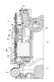
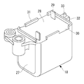
- FIG. 1 is a perspective view of a main part of an inverter-integrated electric compressor according to an embodiment of the present invention
- FIG. 2 is a corresponding cross-sectional view taken along line aa
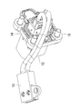
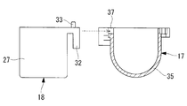
- FIG. FIG. 4 is a perspective view of the back side of the lid that seals the inverter accommodating portion
- FIG. 4 is a perspective view of the power cable alone.
- the inverter-integrated electric compressor 1 includes a cylindrical housing 2 that forms an outer shell.
- the housing 2 has a structure in which a motor housing 3 for incorporating an electric motor (not shown) and a compressor housing (not shown) for incorporating a compression mechanism (not shown) are integrally coupled.
- an electric motor built in the housing 2 and a compression mechanism are connected via a rotating shaft, and the electric motor is rotationally driven via an inverter device 7 described later.
- the compression mechanism is driven, and the low-pressure refrigerant gas sucked into the interior through the suction port 4 provided on the rear end side surface of the motor housing 3 is sucked through the periphery of the electric motor, and is compressed by the compression mechanism. After being compressed and discharged into the compressor housing, it is sent out to the outside.
- the motor housing 3 is formed with a plurality of refrigerant flow passages 5 for circulating the refrigerant along the axial direction on the inner peripheral surface side, and a plurality of installation leg portions 6 of the electric compressor 1 are formed on the outer peripheral portion thereof. It is provided in the place.
- an inverter housing portion 8 for integrally incorporating the inverter device 7 is integrally formed on the outer peripheral portion of the housing 2 (motor housing 3 side).
- the inverter accommodating portion 8 has a substantially square shape in plan view, the bottom surface is a partially flat base surface 9 formed by the wall surface of the motor housing 3, and the flange portion 10 is raised around the periphery. It is configured.
- the inverter accommodating portion 8 is configured to be sealed by attaching the lid 11 shown in FIG. 3 to the flange portion 10 after the inverter device 7 is incorporated.
- a high voltage cable (power supply side cable) 12 is provided on the inner surface side of the lid body 11.
- the high voltage cable 12 is provided with a connector 13 on one end side and a connector terminal 14 connected to a power supply side cable on the other end side.
- the connector 13 at one end is fixedly installed on the inner surface of the lid 11 with a screw 15 at a position corresponding to a PN terminal 24 provided on the main board 20 described later.
- the connector terminal 14 at the other end is fixedly installed by a plurality of screws 16 from the outer surface side with the terminal portion protruding to the outer surface side of the lid 11.
- the high voltage cable 12 forms part of the power supply side cable, and is connected to the power supply unit mounted on the vehicle via the power supply side cable, and the connector 13 provided at one end thereof is connected to the inverter device 7.
- the PN terminal 24 provided on the main board 20 By connecting to the PN terminal 24 provided on the main board 20, a high-voltage DC power fed from the power supply unit is applied to the inverter device 7.
- the inverter device 7 converts high-voltage DC power fed from a power supply unit mounted on a vehicle into three-phase AC power having a required frequency, applies it to the electric motor, and drives the electric motor. .
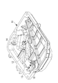
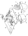
- the inverter device 7 is integrated and incorporated in the inverter housing portion 8, and includes a coil 17 including a housing case that forms a filter circuit for noise removal, and a smoothing device. It is composed of a plurality of high voltage system electrical components such as a capacitor 18, a sub board 19, a main board 20, and the like.
- the inverter device 7 itself may be a known one, but here, in order to integrate, a plurality of electrical components such as a coil 17 and a smoothing capacitor 18 constituting a filter circuit are connected to the main substrate 20 by soldering. Is used.
- the smoothing capacitor 18 is generally configured to be accommodated in a case. As shown in FIGS. 2 and 6, the outer shape is a square shape (cuboid shape), and the upper surface is a flat shape having a substantially flat shape. Is. Electrical components such as a smoothing capacitor 18 and a cased coil 17 (for example, a common mode coil or a normal mode coil) are connected to a high voltage line constituted by a wiring pattern of the main board 20, and are known filters for noise removal. The circuit is configured.
- the sub circuit board 19 is mounted with a communication circuit 21 connected to a communication line from the host controller, and is mounted on a base surface 9 formed on the wall surface of the motor housing 3 which is the bottom surface of the inverter housing portion 8. It is fixedly installed in contact.
- the sub board 19 is electrically connected to the main board 20.
- a switching circuit (not shown) composed of a plurality of switching elements such as IGBTs for converting DC power into three-phase AC power is mounted, and a CPU or the like that controls the switching circuit or the like is mounted.
- a control circuit 22 that operates on voltage is mounted.
- the main board 20 controls the operation of the inverter device 7 based on a control signal from an ECU mounted on the vehicle side, and is fixedly installed inside the inverter accommodating portion 8 via a plurality of bolts 23. ing.
- the main board 20 has a PN terminal 24 for inputting high-voltage DC power from the high-voltage cable 12 through the connector 13 on the upper surface thereof, and three-phase AC power having a required frequency returned from the DC power. And a UVW terminal 25 for outputting.
- the UVW terminal 25 is connected to a glass sealed terminal 26 installed in the inverter housing portion 8 through the motor housing 3, and is connected to an electric motor installed in the motor housing 3 through the glass sealed terminal 26. Three-phase AC power is applied. Further, a high voltage line is connected to the PN terminal 24 by inserting the connector 13 provided on the lid 11 side corresponding to the PN terminal 24. Requires a certain pressing force, and the stress is applied to the main board 20.
- a smoothing capacitor as a plurality of high-voltage system electrical components is provided on the back side of the portion where the PN terminal 24 is installed. 18 and the coil 17 are juxtaposed, and the smoothing capacitor 18 therein is disposed on the back side thereof so as to face the installation position of the PN terminal 24.
- the smoothing capacitor 18 has a rectangular shape (a rectangular parallelepiped shape) as its outer shape, and is configured to receive stress applied to the main substrate 20 on its upper surface.
- the smoothing capacitor 18 is housed in a resin housing case 27 whose upper end is opened and fixed by filling with a resin material 28.
- the terminals 29 are projected, and the terminals 29 are mounted on the main board 20 by being soldered to the main board 20.
- a plurality of concave portions 30 and convex portions 31 are alternately provided at the periphery of the upper end opening having a short shape of the storage case 27 of the smoothing capacitor 18 so that at least one convex portion 31 exists on each side. ing.
- the convex portion 31 supports the lower surface side portion of the main board 20 facing the position where the PN terminal 24 is installed on the upper surface, and stress applied to the main board 20 when the connector 13 is inserted into the PN terminal 24. It is for supporting.
- the recess 30 has an influence on the dimensional accuracy of the upper surface of the projection 31 by escaping from the recess 30 when the resin material 28 filled in the case 27 overflows when the smoothing capacitor 18 is manufactured. It is to prevent it from reaching.
- a hook-shaped fitting convex portion (fitting portion) 32 that extends laterally from one side of the periphery of the upper end opening and is refracted further downward. Is integrally molded.
- the fitting convex portion 32 is for integrally coupling the coil 17 and the smoothing capacitor 18 which are another high voltage system electrical component, and is a concave shape provided in a storage case 35 on the coil 17 side which will be described later. Are fitted into a fitting recess (fitting portion) 37 to integrally couple them.
- a projection (positioning means) 33 for positioning the smoothing capacitor 18 and the coil 17 is integrally formed on the upper surface of the fitting protrusion 32 so as to protrude upward when assembled to the main board 20.
- the protrusion 33 is fitted in a positioning hole 34 provided in the main board 20 and is used for positioning the smoothing capacitor 18 and the coil 17 at a predetermined assembly position on the main board 20.
- the coil 17, which is another high-voltage electrical component is also housed in a resin housing case 35 and fixed with a resin material, and both end terminals 36 are soldered to the main board 20. As a result, it is mounted on the main board 20.
- a hook-like fitting convex portion (fitting portion) 32 provided on the smoothing capacitor 18 side is fitted into the storage case 35 of the coil 17, and the coil 17 and the smoothing capacitor 18 are fitted.
- a concave fitting concave portion (fitting portion) 37 are integrally provided.
- the storage case 27 and 35 of the coil 17 and the smoothing capacitor 18 are fastened and fixed at predetermined positions on the back side of the main board 20 via screws 38 and 39 (see FIG. 1).
- the coil 17 and the smoothing capacitor 18 are housed in the inverter housing portion 8 in a state of being integrally assembled with the main substrate 20, and the bottom portion thereof is fixedly installed on the bottom surface of the inverter housing portion 8 with silicon adhesive or the like. It is like that.
- a plurality of high-voltage electrical components constituting the filter circuit for noise removal of the inverter device 7 are provided with the coil 17 and the smoothing capacitor 18, and the coil 17 and the smoothing capacitor 18 are mounted on the main board 20.
- the main circuit board 20 is provided with a noise removing filter circuit.
- the coil 17 and the smoothing capacitor 18 that are a plurality of high-voltage electric parts are integrally coupled via the fitting convex part 32 and the fitting concave part 37 provided in the storage cases 27 and 35, respectively.
- the main board 20 is integrated and accommodated in the inverter accommodating portion 8. I can do it.
- the terminal block or the bus bar is inserted.
- the power supply side cable 12 can be directly connected without using the above.
- a noise removing filter circuit can be formed on the main board 20.
- the configuration can be simplified, the cost can be reduced, and the size and weight can be reduced. At the same time, the number of man-hours can be reduced and the reliability can be improved by reducing the number of connections by the bus bar.
- the plurality of high-voltage system electrical components 17 and 18 are coupled together via the fitting convex portion 32 and the fitting concave portion 37 provided in the mutual storage cases 27 and 35, and the one storage case 27 side. It is installed at a predetermined position on the back side of the main board 20 through positioning protrusions 33 provided on the main board 20. Therefore, high voltage system electrical components such as the smoothing capacitor 18 and the coil 17 which are relatively heavy and large components are integrally coupled and accommodated in the inverter accommodating portion 8 while being positioned and assembled on the back side of the main board 20. Can be installed. Therefore, as compared with the case where a plurality of high-voltage electrical parts 17 and 18 are individually assembled, the assemblability and accuracy thereof can be improved and the productivity can be improved.
- the plurality of high-voltage electrical components 17 and 18 are respectively formed as a smoothing capacitor 18 and a coil 17 containing resin-made storage cases 27 and 35, and the storage cases 27 and 35 are connected to the back side of the main board 20 with screws 38, By being assembled and fixed integrally through 39, the inverter is accommodated and installed in the inverter accommodating portion 8. Therefore, the smoothing capacitor 18 and the coil 17 constituting the filter circuit for noise removal are firmly fixed to the back side of the main board 20 by screws 38 and 39 via the storage cases 27 and 35, and are integrated and incorporated. be able to. Therefore, not only the assemblability and its accuracy can be improved, but also the vibration resistance against running vibration and the like can be sufficiently secured.
- the positioning projection 33 is integrally projected and formed on the upper surface of the fitting convex portion 32 of the housing case 27 made of resin, and is provided on the main substrate 20.
- the positioning hole 34 is configured to be fitted. Therefore, the coil 17 and the smoothing capacitor 18 that are integrally coupled are fitted into the positioning hole 34 on the main board 20 side by fitting the protrusion 33 integrally formed with the fitting convex portion 32 in one resin storage case 27. At the same time, it can be positioned and assembled to the main board 20. Therefore, it is possible to improve the assembly of the inverter device 7 by accurately positioning and assembling a plurality of high-voltage electrical components 17 and 18 at a low cost without increasing the number of parts and the number of assembly steps. can do.
- the connector 13 provided at one end of the power supply side cable 12 is provided on the inner surface side of the position corresponding to the PN terminal 24 on the lid 11 side that seals the inverter accommodating portion 8.
- the connector 13 provided on the inner surface side of the lid 11 is simultaneously connected to the PN terminal.
- the smoothing capacitor 18, which is one of the plurality of high voltage system electrical components, is arranged on the back surface side corresponding to the installation position of the PN terminal 24 installed on the main board 20.
- the smoothing capacitor 18 is configured to receive stress applied to the main board 20 when the connector 13 is inserted into the PN terminal 24. Therefore, when the connector 13 provided at one end of the power supply side cable 12 is inserted into the PN terminal 24 provided on the main board 20 and the power supply side cable 12 is connected, The applied stress can be reduced by supporting the applied stress by the smoothing capacitor 18 disposed on the back side corresponding to the installation position of the PN terminal 24. As a result, it is possible to reliably eliminate such a situation that the main board 20 and its mounted components are damaged by the stress caused by the pushing force when the connector 13 is inserted.
- this invention is not limited to the invention concerning the said embodiment, In the range which does not deviate from the summary, it can change suitably.
- the smoothing capacitor 18 is used as the high-voltage electrical component disposed on the back surface side corresponding to the installation position of the PN terminal 24 on the main board 20 . Not limited to this. It is good also as a structure supported by the storage case 35 as the coils 17, such as a common mode coil and a normal mode coil containing the storage case 35.
- fitting portions 32 and 37 that integrally couple the coil 17 and the smoothing capacitor 18 are integrally formed in the respective storage cases 27 and 35.
- the fitting portions 32 and 37 are the same as those in the above embodiment.
- the hook-like fitting convex part 32 and the concave fitting concave part 37 are not necessarily required, and any structure can be used as long as they can be coupled.
- the protrusion 33 as positioning means provided on the upper surface of the fitting convex portion 32 may be provided in either the fitting portion 32 or 37 or the storage case 27 or 35, and the fitting convex portion 32 is not necessarily required. It is not necessary to be provided on the upper surface of the.
- the high voltage cable 12 is installed in the lid 11 and the power supply side cable is connected thereto.
- the power supply side cable may be constituted by a single cable.
- the inverter device 7 may have any configuration as long as the PN terminal 24 is provided on the main board 20 and the power supply side cable is connected.
- the inverter device 7 may be integrated into a unit via a resin structure and incorporated in the inverter accommodating portion 8.
Abstract
Description
すなわち、本発明にかかるインバータ一体型電動圧縮機は、ハウジングの外周に設けられたインバータ収容部に、インバータ装置が組み込まれて一体化されているインバータ一体型電動圧縮機において、インバータ装置のメイン基板上に高電圧の直流電力を入力するP-N端子を設け、該P-N端子にその一端側に設けられているコネクタを差し込むことにより電源側ケーブルが接続可能とされているとともに、前記メイン基板の前記P-N端子が設置されている部位の裏面側に複数の高電圧系電装部品を配設し、実装することにより、該メイン基板上にノイズ除去用のフィルタ回路が設けられ、前記複数の高電圧系電装部品が、互いの収納ケースに設けられた嵌合部を介して一体に結合され、その何れかの収納ケース側に設けられた位置決め手段を介して前記メイン基板の裏面側の所定位置に設置されていることを特徴とする。 In order to solve the above-described problems, the inverter-integrated electric compressor of the present invention employs the following means.
That is, an inverter-integrated electric compressor according to the present invention is an inverter-integrated electric compressor in which an inverter device is integrated and integrated in an inverter housing portion provided on the outer periphery of a housing. A PN terminal for inputting high-voltage DC power is provided above, and a power source cable can be connected by inserting a connector provided at one end of the PN terminal. By disposing and mounting a plurality of high voltage system electrical components on the back side of the portion where the PN terminal is installed on the substrate, a filter circuit for noise removal is provided on the main substrate, A plurality of high-voltage electrical components are joined together via a fitting portion provided in each storage case, and a positioning provided on either storage case side. Characterized in that it is installed via a means at a predetermined position on the back surface side of the main board.
図1には、本発明の一実施形態の係るインバータ一体型電動圧縮機の主要部の斜視図が示され、図2には、そのa-a縦断面相当図が示され、図3には、インバータ収容部を密閉する蓋体の裏面側斜視図が示され、図4には、電源ケーブル単体の斜視図が示されている。
インバータ一体型電動圧縮機1は、外殻を構成する円筒形状とされたハウジング2を備えている。ハウジング2は、電動モータ(図示省略)を内蔵するためのモータハウジング3と、圧縮機構(図示省略)を内蔵するための圧縮機ハウジング(図示省略)とを一体に結合した構成とされている。 An embodiment according to the present invention will be described below with reference to FIGS.
FIG. 1 is a perspective view of a main part of an inverter-integrated electric compressor according to an embodiment of the present invention, FIG. 2 is a corresponding cross-sectional view taken along line aa, and FIG. FIG. 4 is a perspective view of the back side of the lid that seals the inverter accommodating portion, and FIG. 4 is a perspective view of the power cable alone.
The inverter-integrated
また、P-N端子24には、P-N端子24と対応して蓋体11側に設けられているコネクタ13が差し込まれることにより、高電圧ラインが接続されるが、コネクタ13を差し込む際には一定以上の押し込み力が必要であり、その応力がメイン基板20にかかるようになっている。 The
Further, a high voltage line is connected to the
2 ハウジング
3 モータハウジング
7 インバータ装置
8 インバータ収容部
11 蓋体
12 高電圧ケーブル(電源側ケーブル)
13 コネクタ
17 コイル(高電圧系電装部品)
18 平滑コンデンサ(高電圧系電装部品)
20 メイン基板
24 P-N端子
27 収納ケース
32 嵌合凸部(嵌合部)
33 突起(位置決め手段)
34 位置決め穴
35 収納ケース
37 嵌合凹部(嵌合部)
38,39 ネジ
DESCRIPTION OF
13
18 Smoothing capacitor (high voltage system electrical parts)
20
33 Protrusion (positioning means)
34
38,39 screw
Claims (5)
- ハウジングの外周に設けられたインバータ収容部に、インバータ装置が組み込まれて一体化されているインバータ一体型電動圧縮機において、
インバータ装置のメイン基板上に高電圧の直流電力を入力するP-N端子を設け、該P-N端子にその一端側に設けられているコネクタを差し込むことにより電源側ケーブルが接続可能とされているとともに、
前記メイン基板の前記P-N端子が設置されている部位の裏面側に複数の高電圧系電装部品を配設し、実装することにより、該メイン基板上にノイズ除去用のフィルタ回路が設けられ、
前記複数の高電圧系電装部品が、互いの収納ケースに設けられた嵌合部を介して一体に結合され、その何れかの収納ケース側に設けられた位置決め手段を介して前記メイン基板の裏面側の所定位置に設置されているインバータ一体型電動圧縮機。 In the inverter-integrated electric compressor in which the inverter device is incorporated and integrated in the inverter housing portion provided on the outer periphery of the housing,
A PN terminal for inputting high-voltage DC power is provided on the main board of the inverter device, and a power source cable can be connected by inserting a connector provided at one end of the PN terminal. And
By disposing and mounting a plurality of high voltage system electrical components on the back side of the portion where the PN terminal is installed on the main substrate, a filter circuit for removing noise is provided on the main substrate. ,
The plurality of high-voltage electrical components are integrally coupled via a fitting portion provided in each other storage case, and the back surface of the main board via positioning means provided on either storage case side Inverter-integrated electric compressor installed at a predetermined position on the side. - 前記複数の高電圧系電装部品は、各々が樹脂製の前記収納ケース入り平滑コンデンサおよびコイルとされ、該収納ケースが前記メイン基板の裏面側にネジを介して一体に組み付け固定されることにより、前記インバータ収容部内に収容設置される構成とされている請求項1に記載のインバータ一体型電動圧縮機。 The plurality of high-voltage electrical parts are each made of a resin-made smoothing capacitor and coil containing the storage case, and the storage case is integrally assembled and fixed to the back side of the main board via screws, The inverter-integrated electric compressor according to claim 1, wherein the inverter-integrated electric compressor is configured to be accommodated and installed in the inverter accommodating portion.
- 前記位置決め手段は、樹脂製とされた前記収納ケースの前記嵌合部の上面に、上方に向けて一体に突出成形され、前記メイン基板に設けられている位置決め穴に嵌合する突起とされている請求項1または2に記載のインバータ一体型電動圧縮機。 The positioning means is a protrusion that is integrally projected upward on the upper surface of the fitting portion of the storage case made of resin, and is a protrusion that fits into a positioning hole provided in the main board. The inverter-integrated electric compressor according to claim 1 or 2.
- 前記電源側ケーブルの一端に設けられている前記コネクタは、前記インバータ収容部を密閉する蓋体側の前記P-N端子と対応する位置の内面側に設けられており、前記蓋体の取付け時、前記P-N端子に差し込み可能とされている請求項1ないし3のいずれかに記載のインバータ一体型電動圧縮機。 The connector provided at one end of the power supply side cable is provided on the inner surface side at a position corresponding to the PN terminal on the lid side that seals the inverter accommodating portion, and when the lid is attached, 4. The inverter-integrated electric compressor according to claim 1, wherein the inverter-integrated electric compressor can be inserted into the PN terminal.
- 前記複数の高電圧系電装部品の1つが、前記メイン基板上に設置されている前記P-N端子の設置位置に対応してその裏面側に配設され、当該高電圧系電装部品により、前記コネクタの前記P-N端子への差し込み時に前記メイン基板に付加される応力を受ける構成とされている請求項1ないし4のいずれかに記載のインバータ一体型電動圧縮機。
One of the plurality of high-voltage system electrical components is disposed on the back side corresponding to the installation position of the PN terminal installed on the main board, and the high-voltage system electrical components provide the 5. The inverter-integrated electric compressor according to claim 1, wherein the inverter-integrated electric compressor is configured to receive stress applied to the main board when the connector is inserted into the PN terminal.
Priority Applications (3)
| Application Number | Priority Date | Filing Date | Title |
|---|---|---|---|
| US14/652,399 US9948165B2 (en) | 2013-02-20 | 2014-01-08 | Inverter-integrated electric compressor |
| DE112014000405.7T DE112014000405T5 (en) | 2013-02-20 | 2014-01-08 | Electric compressor with integrated inverter |
| CN201480003577.6A CN104871410B (en) | 2013-02-20 | 2014-01-08 | Inverter-integrated electric compressor |
Applications Claiming Priority (2)
| Application Number | Priority Date | Filing Date | Title |
|---|---|---|---|
| JP2013-031407 | 2013-02-20 | ||
| JP2013031407A JP6029484B2 (en) | 2013-02-20 | 2013-02-20 | Inverter-integrated electric compressor |
Publications (1)
| Publication Number | Publication Date |
|---|---|
| WO2014129218A1 true WO2014129218A1 (en) | 2014-08-28 |
Family
ID=51391014
Family Applications (1)
| Application Number | Title | Priority Date | Filing Date |
|---|---|---|---|
| PCT/JP2014/050135 WO2014129218A1 (en) | 2013-02-20 | 2014-01-08 | Inverter-integrated electric compressor |
Country Status (5)
| Country | Link |
|---|---|
| US (1) | US9948165B2 (en) |
| JP (1) | JP6029484B2 (en) |
| CN (1) | CN104871410B (en) |
| DE (1) | DE112014000405T5 (en) |
| WO (1) | WO2014129218A1 (en) |
Families Citing this family (7)
| Publication number | Priority date | Publication date | Assignee | Title |
|---|---|---|---|---|
| DE112015003297T5 (en) * | 2014-09-02 | 2017-04-27 | Aisin Aw Co., Ltd. | terminal base |
| JP6516357B2 (en) * | 2015-04-20 | 2019-05-22 | 三菱重工サーマルシステムズ株式会社 | Circuit board for electric power conversion and electric compressor |
| JP6291463B2 (en) * | 2015-09-24 | 2018-03-14 | 矢崎総業株式会社 | Noise filter and wire harness |
| JP6948141B2 (en) * | 2017-04-11 | 2021-10-13 | サンデン・オートモーティブコンポーネント株式会社 | Inverter integrated electric compressor and method for manufacturing it |
| JP7135967B2 (en) * | 2019-03-27 | 2022-09-13 | 株式会社豊田自動織機 | electric compressor |
| JP7018992B2 (en) * | 2020-06-17 | 2022-02-14 | 三菱重工サーマルシステムズ株式会社 | Circuit components, boards, circuit assemblies, and electric compressors for vehicles with anti-vibration fixed structures |
| EP4138275A1 (en) * | 2021-08-19 | 2023-02-22 | Valeo Japan Co., Ltd | A cover for a housing of an electric machine |
Citations (6)
| Publication number | Priority date | Publication date | Assignee | Title |
|---|---|---|---|---|
| JPH11135965A (en) * | 1997-10-30 | 1999-05-21 | Nippon Seiki Co Ltd | Retaining structure of printed substrate with connector |
| JP2000261160A (en) * | 1999-03-12 | 2000-09-22 | Harness Syst Tech Res Ltd | Branch connection box |
| JP2005036773A (en) * | 2003-07-18 | 2005-02-10 | Denso Corp | Inverter-integrated motor-driven compressor for vehicle |
| JP2006230064A (en) * | 2005-02-16 | 2006-08-31 | Toyota Motor Corp | Power conversion unit |
| JP2011163232A (en) * | 2010-02-10 | 2011-08-25 | Mitsubishi Heavy Ind Ltd | Inverter-integrated electric-powered compressor and assembling method thereof |
| JP2012209414A (en) * | 2011-03-29 | 2012-10-25 | Mitsubishi Heavy Ind Ltd | Electronic substrate and inverter-integrated electric compressor |
Family Cites Families (12)
| Publication number | Priority date | Publication date | Assignee | Title |
|---|---|---|---|---|
| US6392364B1 (en) | 1999-06-21 | 2002-05-21 | Denso Corporation | High voltage discharge lamp apparatus for vehicles |
| US20060120001A1 (en) | 2004-12-03 | 2006-06-08 | Weber William J | Modular power supply assembly |
| JP4853077B2 (en) * | 2006-03-29 | 2012-01-11 | 株式会社豊田自動織機 | Electric compressor |
| JP2007295639A (en) | 2006-04-20 | 2007-11-08 | Denso Corp | Motor drive for vehicle |
| JP4719134B2 (en) | 2006-11-22 | 2011-07-06 | 三菱重工業株式会社 | Inverter-integrated electric compressor |
| DE102008051509A1 (en) | 2007-10-16 | 2009-04-30 | Denso Corp., Kariya-shi | Mounting structure for motor drive circuit and electric compressor |
| JP5291436B2 (en) | 2008-11-06 | 2013-09-18 | サンデン株式会社 | Inverter-integrated electric compressor |
| JP5582749B2 (en) * | 2009-09-24 | 2014-09-03 | 三菱重工業株式会社 | Inverter-integrated electric compressor |
| JP4898931B2 (en) | 2010-02-10 | 2012-03-21 | 三菱重工業株式会社 | Inverter-integrated electric compressor |
| JP5382036B2 (en) | 2011-03-16 | 2014-01-08 | 株式会社豊田自動織機 | Electric compressor |
| JP5273573B2 (en) * | 2011-05-13 | 2013-08-28 | 株式会社デンソー | Motor drive device |
| JP5743851B2 (en) | 2011-10-31 | 2015-07-01 | 日立オートモティブシステムズ株式会社 | Electronic equipment |
-
2013
- 2013-02-20 JP JP2013031407A patent/JP6029484B2/en active Active
-
2014
- 2014-01-08 WO PCT/JP2014/050135 patent/WO2014129218A1/en active Application Filing
- 2014-01-08 DE DE112014000405.7T patent/DE112014000405T5/en active Pending
- 2014-01-08 US US14/652,399 patent/US9948165B2/en active Active
- 2014-01-08 CN CN201480003577.6A patent/CN104871410B/en active Active
Patent Citations (6)
| Publication number | Priority date | Publication date | Assignee | Title |
|---|---|---|---|---|
| JPH11135965A (en) * | 1997-10-30 | 1999-05-21 | Nippon Seiki Co Ltd | Retaining structure of printed substrate with connector |
| JP2000261160A (en) * | 1999-03-12 | 2000-09-22 | Harness Syst Tech Res Ltd | Branch connection box |
| JP2005036773A (en) * | 2003-07-18 | 2005-02-10 | Denso Corp | Inverter-integrated motor-driven compressor for vehicle |
| JP2006230064A (en) * | 2005-02-16 | 2006-08-31 | Toyota Motor Corp | Power conversion unit |
| JP2011163232A (en) * | 2010-02-10 | 2011-08-25 | Mitsubishi Heavy Ind Ltd | Inverter-integrated electric-powered compressor and assembling method thereof |
| JP2012209414A (en) * | 2011-03-29 | 2012-10-25 | Mitsubishi Heavy Ind Ltd | Electronic substrate and inverter-integrated electric compressor |
Also Published As
| Publication number | Publication date |
|---|---|
| US9948165B2 (en) | 2018-04-17 |
| CN104871410A (en) | 2015-08-26 |
| JP6029484B2 (en) | 2016-11-24 |
| CN104871410B (en) | 2017-09-01 |
| DE112014000405T5 (en) | 2015-09-24 |
| US20150333604A1 (en) | 2015-11-19 |
| JP2014161188A (en) | 2014-09-04 |
Similar Documents
| Publication | Publication Date | Title |
|---|---|---|
| WO2014129218A1 (en) | Inverter-integrated electric compressor | |
| US10008895B2 (en) | Inverter-integrated electric compressor | |
| JP5511232B2 (en) | Inverter module and inverter-integrated electric compressor using the same | |
| US10253763B2 (en) | Motor-driven compressor | |
| US8742709B2 (en) | Integrated-inverter electric compressor | |
| JP6096003B2 (en) | Inverter-integrated electric compressor | |
| JP6037809B2 (en) | Inverter-integrated electric compressor | |
| JP6195453B2 (en) | Inverter-integrated electric compressor | |
| US10132535B2 (en) | Inverter-integrated electric compressor | |
| WO2010092896A1 (en) | Inverter device and inverter-integrated electric compressor | |
| US9929618B2 (en) | Inverter-integrated electric compressor | |
| JP6021623B2 (en) | Inverter-integrated electric compressor | |
| JP6544201B2 (en) | Automotive air conditioner | |
| JP5574794B2 (en) | Inverter-integrated electric compressor | |
| JP2018178829A (en) | Electric compressor |
Legal Events
| Date | Code | Title | Description |
|---|---|---|---|
| 121 | Ep: the epo has been informed by wipo that ep was designated in this application |
Ref document number: 14754853 Country of ref document: EP Kind code of ref document: A1 |
|
| WWE | Wipo information: entry into national phase |
Ref document number: 14652399 Country of ref document: US |
|
| WWE | Wipo information: entry into national phase |
Ref document number: 1120140004057 Country of ref document: DE Ref document number: 112014000405 Country of ref document: DE |
|
| 122 | Ep: pct application non-entry in european phase |
Ref document number: 14754853 Country of ref document: EP Kind code of ref document: A1 |