WO2014125996A1 - 移動局装置、集積回路、通信方法及び通信プログラム - Google Patents
移動局装置、集積回路、通信方法及び通信プログラム Download PDFInfo
- Publication number
- WO2014125996A1 WO2014125996A1 PCT/JP2014/052789 JP2014052789W WO2014125996A1 WO 2014125996 A1 WO2014125996 A1 WO 2014125996A1 JP 2014052789 W JP2014052789 W JP 2014052789W WO 2014125996 A1 WO2014125996 A1 WO 2014125996A1
- Authority
- WO
- WIPO (PCT)
- Prior art keywords
- detection threshold
- threshold value
- information
- channel
- mobile station
- Prior art date
- Legal status (The legal status is an assumption and is not a legal conclusion. Google has not performed a legal analysis and makes no representation as to the accuracy of the status listed.)
- Ceased
Links
Images













Classifications
-
- H—ELECTRICITY
- H04—ELECTRIC COMMUNICATION TECHNIQUE
- H04W—WIRELESS COMMUNICATION NETWORKS
- H04W48/00—Access restriction; Network selection; Access point selection
- H04W48/16—Discovering, processing access restriction or access information
-
- H—ELECTRICITY
- H04—ELECTRIC COMMUNICATION TECHNIQUE
- H04W—WIRELESS COMMUNICATION NETWORKS
- H04W24/00—Supervisory, monitoring or testing arrangements
- H04W24/08—Testing, supervising or monitoring using real traffic
-
- H—ELECTRICITY
- H04—ELECTRIC COMMUNICATION TECHNIQUE
- H04W—WIRELESS COMMUNICATION NETWORKS
- H04W28/00—Network traffic management; Network resource management
- H04W28/16—Central resource management; Negotiation of resources or communication parameters, e.g. negotiating bandwidth or QoS [Quality of Service]
- H04W28/18—Negotiating wireless communication parameters
-
- H—ELECTRICITY
- H04—ELECTRIC COMMUNICATION TECHNIQUE
- H04W—WIRELESS COMMUNICATION NETWORKS
- H04W4/00—Services specially adapted for wireless communication networks; Facilities therefor
- H04W4/02—Services making use of location information
-
- H—ELECTRICITY
- H04—ELECTRIC COMMUNICATION TECHNIQUE
- H04W—WIRELESS COMMUNICATION NETWORKS
- H04W52/00—Power management, e.g. Transmission Power Control [TPC] or power classes
- H04W52/02—Power saving arrangements
- H04W52/0209—Power saving arrangements in terminal devices
- H04W52/0225—Power saving arrangements in terminal devices using monitoring of external events, e.g. the presence of a signal
- H04W52/0229—Power saving arrangements in terminal devices using monitoring of external events, e.g. the presence of a signal where the received signal is a wanted signal
-
- H—ELECTRICITY
- H04—ELECTRIC COMMUNICATION TECHNIQUE
- H04W—WIRELESS COMMUNICATION NETWORKS
- H04W52/00—Power management, e.g. Transmission Power Control [TPC] or power classes
- H04W52/02—Power saving arrangements
- H04W52/0209—Power saving arrangements in terminal devices
- H04W52/0225—Power saving arrangements in terminal devices using monitoring of external events, e.g. the presence of a signal
- H04W52/0245—Power saving arrangements in terminal devices using monitoring of external events, e.g. the presence of a signal according to signal strength
-
- H—ELECTRICITY
- H04—ELECTRIC COMMUNICATION TECHNIQUE
- H04W—WIRELESS COMMUNICATION NETWORKS
- H04W56/00—Synchronisation arrangements
-
- H—ELECTRICITY
- H04—ELECTRIC COMMUNICATION TECHNIQUE
- H04W—WIRELESS COMMUNICATION NETWORKS
- H04W72/00—Local resource management
- H04W72/04—Wireless resource allocation
- H04W72/044—Wireless resource allocation based on the type of the allocated resource
- H04W72/0453—Resources in frequency domain, e.g. a carrier in FDMA
-
- H—ELECTRICITY
- H04—ELECTRIC COMMUNICATION TECHNIQUE
- H04W—WIRELESS COMMUNICATION NETWORKS
- H04W72/00—Local resource management
- H04W72/02—Selection of wireless resources by user or terminal
-
- Y—GENERAL TAGGING OF NEW TECHNOLOGICAL DEVELOPMENTS; GENERAL TAGGING OF CROSS-SECTIONAL TECHNOLOGIES SPANNING OVER SEVERAL SECTIONS OF THE IPC; TECHNICAL SUBJECTS COVERED BY FORMER USPC CROSS-REFERENCE ART COLLECTIONS [XRACs] AND DIGESTS
- Y02—TECHNOLOGIES OR APPLICATIONS FOR MITIGATION OR ADAPTATION AGAINST CLIMATE CHANGE
- Y02D—CLIMATE CHANGE MITIGATION TECHNOLOGIES IN INFORMATION AND COMMUNICATION TECHNOLOGIES [ICT], I.E. INFORMATION AND COMMUNICATION TECHNOLOGIES AIMING AT THE REDUCTION OF THEIR OWN ENERGY USE
- Y02D30/00—Reducing energy consumption in communication networks
- Y02D30/70—Reducing energy consumption in communication networks in wireless communication networks
Definitions
- the present invention relates to a mobile station device, an integrated circuit, a communication method, and a communication program.
- a wireless communication system related to a mobile phone a plurality of base station devices are mainly connected to each other by wire.
- the base station apparatus is wirelessly connected to a mobile station apparatus used by the user. Therefore, the area that can be communicated with the wireless communication system is limited to the range (cell) where radio waves can reach from each base station device, but communication can be performed in a wide range of places by arranging multiple base station devices at different positions. Is possible. Also, wireless communication systems with different cell arrangements and frequency bands may be used depending on the country, operator, communication service, etc. in operation.
- the mobile station apparatus may move out of the range (out of service area) of the area (cell) where radio waves reach from the base station apparatus.
- the mobile station apparatus performs processing (cell search) for searching for a base station apparatus capable of communication in order to make communication possible outside the service area.
- the cell search mainly includes reception intensity measurement and synchronization processing. After successful cell search, communication with other mobile station devices becomes possible.
- the mobile station apparatus In cell search outside the service area (for example, cell search when moving from Japan to Europe), the mobile station apparatus generally measures the reception strength for all channels that can be received by an available communication system, and then Perform synchronous processing. Therefore, the cell search has a drawback that it takes a long time and power consumption increases.
- a conventional cell search for all channels
- MCC Mobile Country Code
- the search target frequency is limited to the frequency of the operator who provides the communication service in the country, and it is unnecessary to acquire the notification information of the operator who does not provide the communication service.
- Cell search is omitted.
- cell search may be restricted even in a frequency band that can be used by a mobile station device such as a mobile phone. For example, when the operating frequency band is changed to a frequency band in which cell search is restricted at a certain time, there is a problem that cell search is not performed and communication cannot be performed. Further, in the communication method of Patent Document 1, when the mobile station apparatus determines to perform a cell search using the stored history information, the mobile station apparatus generates a large number of received waves due to noise in a frequency band that is not operated, weak interference waves, and the like. There is a problem of detecting and performing unnecessary synchronization processing.
- the present invention has been made in view of the above points, and provides a mobile station device, an integrated circuit, a communication method, and a communication program that reduce processing time and power consumption related to cell search.
- the present invention has been made to solve the above problems, and one aspect of the present invention provides a detection threshold value for detecting a received wave from a base station apparatus based on use environment information indicating a use environment of the own apparatus.
- the detection threshold value changing unit to be changed, the channel selecting unit for selecting a channel having a reception level higher than the detection threshold value from the channels constituting the received wave, and the received wave of the channel selected by the channel selecting unit are synchronized.
- a synchronization processing unit is synchronized.
- processing time and power consumption related to cell search can be reduced.
- FIG. 1 is a conceptual diagram showing a communication system according to a first embodiment of the present invention. It is a schematic block diagram which shows the structure of the mobile station apparatus which concerns on this embodiment. The schematic block diagram which shows the structure of the control part which concerns on this embodiment is shown. It is a figure which shows the example of the detection threshold value corresponding
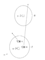
- FIG. 1 is a conceptual diagram showing a communication system 1 according to the present embodiment.
- the communication system 1 includes a plurality (two in the example shown in FIG. 1) of base station apparatuses 11 and 12 and a plurality (two in the example shown in FIG. 1) of mobile station apparatuses 21 and 22. Is done.
- the base station apparatuses 11 and 12 transmit and receive signals using radio waves between the backbone network (CN: Core Network, not shown) and the mobile station apparatuses 21 and 22 located in the cells 11c and 12c. It is a device to do.
- the base station apparatuses 11 and 12 may be abbreviated as eNB (evolved Node B).
- the cells 11c and 12c are areas (areas) in which the base station apparatuses 11 and 12 can transmit and receive signals to and from the mobile station apparatuses 21 and 22 using radio waves, respectively. Each of base station apparatuses 11 and 12 is arranged at a different position.
- the base station apparatuses 11 and 12 may be either a large-scale base station apparatus (macro cell) or a small base station apparatus (for example, a micro cell, a pico cell, or a femto cell).
- the macro cell is a cell 11c or 12c having a radius of about several hundred m to several km, or a base station apparatus having the cell.
- the microcell is a cell 11c or 12c having a radius of about several tens of meters to several hundreds of meters, or a base station device having the cells.
- the pico cell is a cell 11c, 12c having a radius of about several meters to several tens of meters, or a base station device having the cell.
- the femtocell is a cell 11c or 12c having a radius of several meters or less, or a base station apparatus having the cell.
- the femtocell is also called a home base station apparatus (HeNB: Home eNodeB). Accordingly, the cells 11c, 12c and the like connected to one network form a service area where communication can be performed on the network.
- HeNB Home eNodeB
- the network connected to the base station apparatuses 11 and 12 is, for example, a PLMN (Public Land Mobile Network, public wireless communication network).
- the PLMN is a network in which a communication carrier provides communication services to users (subscribers).
- the employed communication method, frequency band, connected base station apparatuses 11 and 12 and the like may differ depending on the country and operator in operation.
- the communication system is, for example, LTE (Long Term Evolution), LTE-A (LTE-Advanced), W-CDMA (Wideband Code Division Multiple Access), GSM (registered trademark) (Global System for Mobile, etc.).
- the mobile station devices 21 and 22 are devices that realize communication with a communication partner by transmitting and receiving signals by radio waves via the base station devices 11 and 12, respectively.
- the mobile station apparatuses 21 and 22 are also referred to as a terminal apparatus or a user apparatus (UE: User Equipment).
- the mobile station devices 21 and 22 are, for example, mobile phones, multi-function mobile phones (including so-called smartphones), tablet terminal devices, and the like.
- the service area does not always occupy the entire space.
- the mobile station devices 21 and 22 may not be able to receive signals from the base station devices 11 and 12 due to the arrangement of the base station devices 11 and 12, the output of their radio waves, the arrangement of buildings and other obstacles, the noise source, and the like. is there.
- the arrow starting from the mobile station device 21 indicates that the mobile station device 21 was in a position belonging to the cell 11c but then moved out of the service area (out of service area) including the cell 11c.
- the arrow starting from the mobile station device 22 indicates that the mobile station device 21 was originally in a position belonging to the cell 11c, but sequentially moved out of range, cell 12c, and out of range.
- the mobile station devices 21 and 22 search for the base station devices 11 and 12 related to the cell to which the own device belongs (located) when starting up or when the mobile station devices 21 and 22 are located outside the service area and cannot communicate. ) When the search is successful, the mobile station apparatuses 21 and 22 can communicate with the base station apparatuses 11 and 12.
- the configuration of the mobile station apparatus 21 (Configuration of mobile station device) Next, the configuration of the mobile station apparatus 21 according to this embodiment will be described. Since the mobile station device 22 has the same configuration as the mobile station device 21, the description of the mobile station device 21 is cited. In the following description, the mobile station apparatus 21 takes an example in which communication is mainly performed using the base station apparatus 11, but in the present embodiment, the mobile station apparatus 21 is not limited to this, and the mobile station apparatus 21 may be another base station apparatus. For example, the base station apparatus 12 may be used.
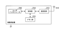
- FIG. 2 is a schematic block diagram showing the configuration of the mobile station apparatus 21 according to this embodiment.
- the mobile station device 21 includes an antenna 212, a transmission / reception unit 213, a control unit 214, a memory unit (storage unit) 215, and a user interface 216.
- the antenna 212 receives a reception wave from the base station apparatus 11, that is, a reception signal in a radio frequency band reached by the radio wave, and outputs the reception signal to the transmission / reception unit 213.
- the antenna 212 transmits the radio frequency band transmission signal input from the transmission / reception unit 213 to the base station apparatus 11 by radio waves.
- the transmission / reception unit 213 converts the reception signal in the radio frequency band input from the antenna 212 into a reception signal in the base frequency band, and outputs the converted reception signal to the control unit 214.
- the transmission / reception unit 213 converts the transmission signal in the base frequency band input from the control unit 214 into a radio frequency band, and outputs the converted transmission signal to the antenna 212. Further, the transmission / reception unit 213 measures the reception level (reception signal strength, RSSI: Received Signal Strength Indicator) received from the base station apparatus 11 for each channel.
- the transmission / reception unit 213 outputs received signal strength information indicating the received signal strength measured for each channel to the control unit 214.
- the channel is a frequency or frequency band that constitutes a radio wave used for communication, and is a frequency or frequency band that is a unit for allocating data.
- each channel is arranged at intervals of 200 kHz.
- a channel is also called a subcarrier, and the bandwidth per channel is 15 kHz.
- a plurality of channels (for example, about 600 when the bandwidth is 10 MHz) are used for communication between the mobile station device 21 and the base station device 11.
- the received signal strength (RSSI) is mainly used as an example of the reception level index.
- RSRP Reference Signal Received Power
- RSRQ Reference Signal Recommended Quality
- a reception level index such as signal reception quality (Reference Signal Recommended Quality) may be used.
- the control unit 214 controls processing performed by the mobile station device 21.
- the control unit 214 controls input of a reception signal from the transmission / reception unit 213 and output of a transmission signal to the transmission / reception unit 213.
- the control unit 214 outputs user data out of the reception signal input from the transmission / reception unit 213 to the user interface 216, and outputs the user data input from the user interface 216 to the transmission / reception unit 213 as a transmission signal.
- the user data is a signal transmitted to or received from the mobile station apparatus 22 that is a communication partner, for example, an audio signal, a video signal, text data, or the like.
- the control unit 214 controls the start, stop, change of mode, etc.
- the control unit 214 may be used when processing data read from the memory unit 215.
- the control unit 214 stores data generated in the processing in the memory unit 215. For example, when the received signal strength is equal to or lower than a predetermined detection threshold (for example, ⁇ 120 (dBm)) in the entire receivable frequency band, the control unit 214 is located outside the service area. It is determined that If the received signal strength exceeds the detection threshold, the control unit 214 determines that the cell is located within the cell 11c. A more detailed configuration of the control unit 214 will be described later.
- a predetermined detection threshold for example, ⁇ 120 (dBm)
- the user interface 216 presents information corresponding to the received signal input from the control unit 214 to the user, and outputs information received from the user to the control unit 214.
- the user interface 216 causes a sound reproduction unit (for example, a speaker, not shown) to reproduce sound corresponding to the audio signal input from the control unit 214, and the sound collection unit (for example, a microphone, not shown).
- the recorded voice signal is output to the control unit 214.
- the user interface 216 displays an image indicated by the image signal input from the control unit 214 on an image display unit (for example, a display, not shown), and an imaging unit (for example, a camera, not shown) takes an image.
- An image signal indicating the processed image is output to the control unit 214.
- the user interface 216 outputs an operation input signal corresponding to a user operation input detected by an operation input unit (for example, a touch sensor, not shown) to the control unit 214.
- the operation input unit and the image display unit may be a touch panel configured by integrating them.
- a part or all of the sound reproduction unit, the sound collection unit, the image display unit, the imaging unit, and the operation input unit may be integrated with the mobile station device 21 or may be separate.
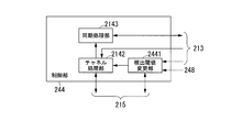
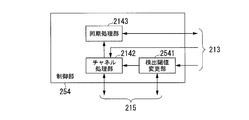
- FIG. 3 is a schematic block diagram showing the configuration of the control unit 214 according to this embodiment.
- the control unit 214 includes a detection threshold value changing unit 2141, a channel processing unit (channel selection unit) 2142, and a synchronization processing unit 2143.
- the user interface 216 is not shown.
- the detection threshold changing unit 2141 determines a detection threshold for detecting the frequency band (channel) of the received signal received from the base station device 11 based on the usage environment information indicating the usage environment of the mobile station device 21.
- the detection threshold value changing unit 2141 reads out the location history information from the memory unit 215, and extracts country information from the latest location history information in the read location history information.
- the location history information is information indicating the history of the base station device 11 related to the cell to which the mobile station device 21 belongs and the network connected to the base station device 11.
- the location history information includes communication operator information and frequency band information in addition to country information.
- the location history information is information included in the notification information (described later).
- the detection threshold value changing unit 2141 reads detection threshold value information corresponding to the extracted country information from the detection threshold value correspondence information stored in the memory unit 215, and outputs the read detection threshold value information to the channel processing unit 2142. As a result, the detection threshold set in the channel processing unit 2142 is changed.
- the detection threshold correspondence information is information in which country information and a detection threshold are associated with each other as use environment information. An example of detection threshold correspondence information will be described later.
- the channel processing unit 2142 selects a channel whose intensity is higher than the detection threshold indicated by the detection threshold information input from the detection threshold changing unit 2141 from the received signal from the base station apparatus 11.
- the received signal strength information is input to the channel processing unit 2142 from the transmission / reception unit 213 for each channel, and is compared with the detection threshold indicated by the detection threshold information input from the detection threshold changing unit 2141.
- the channel processing unit 2142 selects a channel whose received signal strength indicated by the input received signal strength information is larger than the detection threshold indicated by the input detection threshold information.
- the channel processing unit 2142 outputs channel selection information indicating the selected channel to the synchronization processing unit 2143. An example of the channel selection process will be described later.
- the channel processing unit 2142 receives broadcast information from the transmission / reception unit 213 as a received signal from the base station apparatus 11, and extracts area history information from the input broadcast information. .
- the channel processing unit 2142 may store the extracted location history information in the memory unit 215. Further, the channel processing unit 2142 may extract the location history information from the broadcast information demodulated by the synchronization processing (described later) by the synchronization processing unit 2143, and store the extracted location history information in the memory unit 215.
- the synchronization processing unit 2143 performs synchronization processing on the received wave of the channel indicated by the channel selection information input from the channel processing unit 2142.
- channel selection information is input from the channel processing unit 2142, and broadcast information modulated for each channel is input from the transmission / reception unit 213 as a reception signal from the base station apparatus 11.
- the synchronization processing unit 2143 detects a synchronization signal included in broadcast information input for each channel indicated by the input channel selection information.
- the synchronization processing unit 2143 uses the detected synchronization signal to identify data in which broadcast information is configured, and demodulates (decodes) broadcast information from the identified data.
- the synchronization processing unit 2143 tries these processes until a channel (available channel) in which both the detection of the synchronization signal and the demodulation of the broadcast information are successfully detected is detected.
- the synchronization processing unit 2143 outputs the location registration request signal to the transmission / reception unit 213 as a transmission signal using an available channel to the base station apparatus 11 (camp-on).
- the location registration request signal is a signal requesting registration of the own device as a mobile station device used for communication.
- the transmission / reception unit 213 receives the location registration completion signal and the location history information from the base station device 11 so that the mobile station device 21 can communicate.
- An example of the synchronization process will be described later. Both the channel selection process performed by the channel processing unit 2142 and the synchronization process performed by the synchronization processing unit 2143 are collectively referred to as cell search.
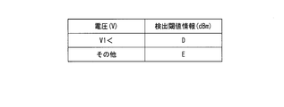
- FIG. 4 is a diagram illustrating an example of detection threshold correspondence information according to the present embodiment.
- the left column shows country information as usage environment information
- the right column shows detection threshold information.
- the second row indicates that the detection threshold value D is associated with the country information AC and BC
- the third row indicates that the detection threshold value E is associated with other country information other than AC and BC. Therefore, the detection threshold value changing unit 2141 sets the detection threshold value D when the country information AC is extracted from the location history information, and the country information (for example, country information CC) other than AC and BC is set from the location history information. If extracted, a detection threshold E is set.
- the detection threshold value changing unit 2141 also sets the detection threshold value E even when the location history information is not stored, such as immediately after the mobile station device 21 is shipped.
- the detection threshold D (for example, ⁇ 105 (dBm)) is the detection threshold E (for example, ⁇ 90 (dBm)).
- a detection threshold D lower than the detection threshold E is selected even when the mobile station device 21 is located in a country that operates an available network and then moves outside the service area. Thereby, even if the mobile station device 21 is located at a position where radio waves do not reach from the base station device 11 or a position where it is difficult to reach (for example, a remote place), channel selection can be performed more reliably from a weak received signal. Can be successful.
- a detection threshold E higher than the detection threshold D is selected.
- the detection threshold correspondence information stored in the memory unit 215 may be associated with country information and country frequency band information indicating a frequency band used in the country.
- the detection threshold value changing unit 2141 selects detection threshold information (for example, detection threshold value D) for the country-specific frequency bands (for example, 800 MHz band and 900 MHz band) corresponding to the country information extracted from the location history information.
- detection threshold value D detection threshold value
- the detection threshold value changing unit 2141 is a detection threshold value that is higher than the detection threshold value information for the country frequency band by a predetermined value.
- detection threshold E is determined.
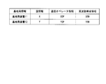
- FIG. 5 is a diagram illustrating an example of location history information according to the present embodiment.
- the location history information shown in FIG. 5 is obtained when the mobile station device 22 (FIG. 1) moves from the position belonging to the cell 11c of the base station device 11 to the range of the cell 12c through the outside of the range. is there.
- base station information indicates information indicating the base station apparatus in which the mobile station apparatus 22 is located.
- the country information indicates information (MCC: Mobile Country Code) indicating a country where a network connected to the base station apparatus is operated.
- the communication operator information indicates information (MNC: Mobile Network Code) indicating an operator (operator) operating a network connected to the base station apparatus.
- MCC Mobile Country Code
- MNC Mobile Network Code
- a combination of MCC and MNC is PLMN identification information (PLMN Identity).
- the frequency band information is information indicating a frequency band in which a network connected to the base station apparatus is operated, that is, a frequency band that can be used by the base station apparatus.
- the memory unit 215 may store not only recent information but also information acquired when the user has been in the area before that as the history information. In that case, the channel processing unit 2142 may delete the earliest information after the number of located history information stored in the memory unit 215 reaches a predetermined upper limit (for example, 10).
- country information X, communication operator information XOP, and frequency band information XBW are associated with the base station apparatus 11.
- country information Y, communication operator information YOP, and frequency band information YBW are associated with the base station apparatus 12. Since the country information X and Y belong to “others” in the third row of FIG. 4, the detection threshold changing unit 2141 performs the detection threshold in the cell search performed before starting communication with the base station apparatuses 11 and 12. Select E. In addition, when either country information AC or BC is extracted from the location history information, the detection threshold value changing unit 2141 selects the detection threshold value D. The detection threshold value changing unit 2141 also sets the detection threshold value E even when the location history information is not stored, such as immediately after the mobile station device 21 is shipped.
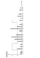
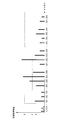
- FIG. 6 is a diagram illustrating an example of received signal strength information.
- the horizontal axis indicates the channel, and the vertical axis indicates the received signal strength.
- FIG. 6 shows the detection thresholds D and E shown in FIG. 4, and the unit of the vertical axis is omitted.
- channels that can be received by the mobile station apparatus 21 are channels 1 to 104, 201 to 224, and 341 to 564.
- the height of the vertical line for each channel indicates the received signal strength of that channel.
- the channel processing unit 2142 When the detection threshold value E (for example, ⁇ 90 (dBm)) is selected by the detection threshold value changing unit 2141, the channel processing unit 2142 has a received signal strength higher than the detection threshold value E from all receivable channels. Select a channel. In this case, the combination of the selected channel and the reception signal distance is two channels (203, ⁇ 88 (dBm)) and (222, ⁇ 85 (dBm)).
- the channel processing unit 2142 selects a channel whose received signal strength is higher than the detection threshold value D.
- the combinations of the selected channel and the received signal strength are (101, ⁇ 104 (dBm)), (202, ⁇ 98 (dBm)), (203, ⁇ 93 (dBm)), (204, ⁇ 99). (DBm)), (222, -85 (dBm)), (223, -94 (dBm)).
- the detection threshold value changing unit 2141 gives a higher detection threshold value to limit the channels selected by the channel processing unit 2142. Thereafter, unnecessary synchronization processing can be further reduced.
- the synchronization process is not completely eliminated, and there remains a possibility of transition to a communicable state for a strong received wave channel.
- the mobile station apparatus 21 can use a network adopting the GSM (registered trademark) system.
- the GSM (registered trademark) system is not used in Japan, but is used in Europe and China. Therefore, when the country information included in the location history information indicates Japan, a detection threshold E that takes a higher value is selected. At this time, the cell search is performed after increasing the detection threshold to reduce the sensitivity.
- the detection threshold E that takes a higher value is selected.
- the cell search is performed after increasing the detection threshold to reduce the sensitivity.
- noise with a reception intensity lower than the detection threshold can be prevented from being erroneously detected. The amount of processing is reduced.
- the user may move to Europe or China after moving out of the service area or after stopping the operation.
- the detection threshold is raised, a received signal with a high reception intensity is detected, so synchronization processing is performed, and the user can communicate using the network that detected the received signal.
- a detection threshold D that takes a lower value is selected. At this time, the cell search is performed after lowering the detection threshold and increasing the sensitivity.
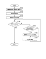
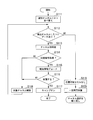
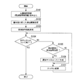
- FIG. 7 is a flowchart showing channel selection processing according to the present embodiment.
- the detection threshold value changing unit 2141 reads the location history information stored in the memory unit 215, and extracts country information from the latest location history information among the read location history information. Thereafter, the process proceeds to step S102.
- the detection threshold value changing unit 2141 reads detection threshold value information based on the extracted country information from the detection threshold value correspondence information stored in the memory unit 215, and sets the read detection threshold value information in the channel processing unit 2142. Thereafter, the process proceeds to step S103.
- Step S ⁇ b> 103 The transmission / reception unit 213 measures the received signal strength of all the receivable channels for the received signal received from the base station apparatus 11. Thereafter, the process proceeds to step S104.
- Step S104 The channel processing unit 2142 determines whether or not the processing of steps S105 to S107 has been completed for all receivable channels. If it is determined that the process has been completed (YES in step S104), the process according to this flowchart is terminated. If it is determined that the process has not been completed (NO in step S104), the process proceeds to step S105.
- Step S105 The channel processing unit 2142 determines whether or not the received signal strength measured for the processing target channel (target channel) is larger than the set detection threshold. If it is determined that the value is larger (YES in step S105), the process proceeds to step S106. When it is determined that it is not large (NO in step S105), the process proceeds to step S107. (Step S106) The channel processing unit 2142 stores the number of the target channel and the received signal strength in association with each other in the memory unit 215, and creates a selection channel list. Thereafter, the process proceeds to step S107. (Step S107) The channel processing unit 2142 changes the target channel to another unprocessed channel. Here, the channel processing unit 2142 may change the target channel to an adjacent channel in ascending order of channel numbers. Thereafter, the process proceeds to step S104. As a result, a selection channel list in which the channel number of the channel whose received signal strength is higher than the detection threshold is associated with the received signal strength of the channel is generated.
- FIG. 8 is a flowchart showing the synchronization processing according to the present embodiment.
- the channel processing unit 2142 rearranges the pairs in which the channel numbers and the received signal strengths included in the generated selected channel list are associated in descending order of the received signal strengths, and generates the detected channel list as channel selection information. To do. Thereafter, the process proceeds to step S112.
- the synchronization processing unit 2143 determines the presence / absence of data included in the detection channel list. If it is determined that there is data in the detection channel list (step S112 YES), the process proceeds to step S113. If it is determined that there is no data in the detection channel list (NO in step S112), the process proceeds to step S119.
- the synchronization processing unit 2143 performs a known synchronization process with the first channel included in the detection channel list as the target channel.
- the synchronization processing unit 2143 detects a synchronization signal assigned to the target channel from the reception signals received from the base station apparatus 11.
- the synchronization signal is, for example, an SCH synchronization signal assigned to a synchronization channel (SCH: Synchronization Channel).
- the synchronization signal includes a cell ID for identifying the base station apparatus 11.
- the synchronization processing unit 2143 identifies the range of each frame in the received signal, that is, the frame timing, based on the received SCH synchronization signal. Thereafter, the process proceeds to step S114.
- Step S114 The synchronization processing unit 2143 determines whether or not an SCH synchronization signal has been acquired. Thereby, the success or failure of the synchronization process is determined. If it is determined that it has been acquired (YES in step S114), the process proceeds to step S115. If it is determined that acquisition has failed (NO in step S114), the process proceeds to step S118. (Step S115) The synchronization processing unit 2143 demodulates (decodes) the BCCH broadcast information included in the received signal. Thereafter, the process proceeds to step S116.
- Step S116 Based on the demodulated BCCH broadcast information, the synchronization processing unit 2143 determines whether or not the base station device 11 is in the cell 11c of the base station device 11, that is, whether or not the base station device 11 is an appropriate base station device. To do. For example, the synchronization processing unit 2143 determines whether or not the PLMN indicated by the BCCH broadcast information matches the PLMN indicated by preset subscriber information (SIM: Subscriber Identity Module). If it is determined that the user is in the area (YES in step S116), the process proceeds to step S117. If it is determined that there is no service area (NO in step S116), the process proceeds to step S118.
- SIM Subscriber Identity Module
- Step S117 The synchronization processing unit 2143 transmits a location registration request signal to the base station apparatus 11, performs location registration (camp-on), and becomes ready for communication. Thereafter, the processing according to this flowchart, and thus the cell search, is completed.
- Step S118 The synchronization processing unit 2143 deletes the head channel number and received signal strength related to the target channel included in the detection channel list, and updates the channel with the next highest received signal strength to the target channel. Thereafter, the process proceeds to step S112.
- Step S119 The synchronization processing unit 2143 determines that there is no cell that can be located. Thereafter, the process proceeds to step S120. (Step S120) Wait for a predetermined time (for example, 10 minutes). Thereafter, the channel selection process (FIG. 7) is repeated.
- the detection threshold based on the country information
- the minimum channel to be subjected to the synchronization process is selected, and the number of selected channels is reduced.
- the amount of power consumed for the synchronization processing is much higher when the synchronization processing is not performed, that is, compared with the channel selection processing (for example, about 50 to 100 times). Therefore, the power consumption of the whole cell search can be reduced by reducing the time and power consumption required for the synchronization processing in the cell search.
- the detection threshold value changing unit 2141 may use communication operator information instead of country information as use environment information. Other points are the same as in the above-described example.
- the detection threshold value changing unit 2141 extracts the communication operator information from the latest location history information among the location history information read from the memory unit 215.
- the detection threshold value changing unit 2141 reads detection threshold value information corresponding to the extracted communication operator information from the detection threshold value correspondence information stored in the memory unit 215.
- FIG. 9 is a diagram illustrating an example of detection threshold value correspondence information according to the present modification.
- the left column shows communication operator information as usage environment information
- the right column shows detection threshold information.
- the second row indicates that the detection threshold value D is associated with the communication operator information AOP and BOP
- the third row indicates that the detection threshold value E is associated with other communication operator information other than the AOP and BOP.
- the detection threshold change unit 2141 sets the detection threshold D, and communication operator information (for example, COP) other than AOP and BOP is set from the location history information. If extracted, a detection threshold E is set. Note that when the location history information is not stored, the detection threshold value changing unit 2141 sets the detection threshold value E.
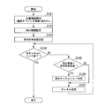
- FIG. 10 is a flowchart showing channel selection processing according to this modification.
- the channel selection process according to this modification includes steps S121 and S122 instead of steps S101 and S102 in the channel selection process shown in FIG.
- Step S121 The detection threshold value changing unit 2141 reads the location history information stored in the memory unit 215, and extracts the communication operator information from the latest location history information among the read location history information. Thereafter, the process proceeds to step S122.
- Step S122 The detection threshold changing unit 2141 reads detection threshold information based on the extracted communication operator information from the detection threshold correspondence information stored in the memory unit 215, and sets the read detection threshold information in the channel processing unit 2142. Thereafter, the process proceeds to step S103.
- the detection threshold value changing unit 2141 may use frequency band information (band information) instead of country information as usage environment information.
- the frequency band indicated by the frequency band information includes a plurality of channels (for example, 72 channels when the bandwidth is 1.4 MHz), and transmits data between the own apparatus (mobile station apparatus 21) and the base station apparatus 11. Or a unit assigned to receive. Other points are the same as in the above-described example.
- the detection threshold value changing unit 2141 extracts the frequency band information from the latest location history information among the location history information read from the memory unit 215.
- the detection threshold value changing unit 2141 reads detection threshold value information corresponding to the extracted frequency band information from the detection threshold value correspondence information stored in the memory unit 215.
- the detection threshold value changing unit 2141 stores the detection threshold information corresponding to the other frequency band information for the frequency band excluding the frequency band indicated by the extracted frequency band information among the frequency bands that can be used by the mobile station apparatus 21. Read from 215.
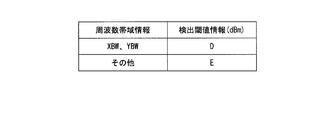
- FIG. 11 is a diagram illustrating an example of detection threshold value correspondence information according to the present modification.
- the left column shows frequency band information as usage environment information
- the right column shows detection threshold information.
- the second row indicates that the detection threshold D is associated with the frequency band information XBW and YBW
- the third row indicates that the detection threshold E is associated with other frequency band information other than XBW and YBW.
- the detection threshold change unit 2141 determines the detection threshold D for the frequency band indicated by the frequency band information XBW, and detects the detection threshold E for other available frequency bands. It is determined.
- the detection threshold value changing unit 2141 includes all the frequencies that can be used by the mobile station device 21 including the frequency indicated by the frequency band information ZBW. Is defined as a detection threshold E.
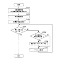
- FIG. 12 is a flowchart showing channel selection processing according to this modification.
- the channel selection process according to this modification includes steps S131 and S132 instead of steps S101 and S102 in the channel selection process shown in FIG.
- Step S131 The detection threshold value changing unit 2141 reads the location history information stored in the memory unit 215, and extracts the frequency band information from the latest location history information among the read location history information. Thereafter, the process proceeds to step S132.
- Step S132 The detection threshold value changing unit 2141 reads detection threshold value information corresponding to the extracted frequency band information out of the frequency bands usable by the mobile station device 21 from the detection threshold value correspondence information stored in the memory unit 215. .
- the detection threshold value changing unit 2141 stores the detection threshold information corresponding to the other frequency band information for the frequency band excluding the frequency band indicated by the extracted frequency band information among the frequency bands that can be used by the mobile station apparatus 21. Read from 215. The detection threshold changing unit 2141 sets the detection threshold information of each available frequency band in the channel processing unit 2142. Thereafter, the process proceeds to step S103.
- FIG. 13 is a diagram illustrating an example of detection threshold information according to the present modification.
- the horizontal axis indicates the channel, and the vertical axis indicates the received signal strength.
- the frequency bands that can be used by the mobile station apparatus 21 are five frequency bands band0, band100, band200, band300, and band500.
- the ranges of channels included in each of band0, band100, band200, band300, and band500 are 0-99, 100-199, 200-200, 300-399, and 500-599.
- the frequency band information extracted by the detection threshold value changing unit 2141 is band0 and band200.
- a broken line indicates that the detection threshold corresponding to band 0 related to channels 0 to 99 and band 200 related to channels 200 to 299 is D, and that the detection threshold corresponding to other channels is E.
- the received signal strength for each channel shown in FIG. 13 is the same as the received signal strength shown in FIG.
- the channel processing unit 2142 selects the next five channels.
- the selected channel and received signal distance pairs are (202, ⁇ 98 (dBm)), (203, ⁇ 93 (dBm)), (204, ⁇ 99 (dBm)), (222, ⁇ 85 (dBm), respectively. )), (223, -94 (dBm)).
- the detection threshold changing unit 2141 determines the detection threshold for each frequency band.
- the detection threshold changing unit 2141 may set the detection threshold for each channel.
- the detection threshold value changing unit 2141 determines the priority for each type of usage environment information according to the usage status, and detects a received wave of a channel with a lower received signal strength as the determined priority is higher.
- the detection threshold is set to be low.
- the detection threshold value changing unit 2141 sets the detection threshold value higher so that the received wave of the channel having the lower received signal strength is not detected as the priority is lower.
- the detection threshold value changing unit 2141 extracts, for example, frequency band information as usage environment information from the location history information read from the memory unit 215, and counts the number of times stored for each frequency band indicated by the extracted frequency band information. To do. Then, the detection threshold value changing unit 2141 determines the priority for each frequency band so that the frequency band having a larger number of counts becomes higher.
- the detection threshold value changing unit 2141 has a priority corresponding to the frequency bandwidth information XBW corresponding to the frequency bandwidth information YBW.
- the priority is set so as to be higher than the priority.
- the priorities corresponding to the frequency band information XBW and YBW are referred to as priorities 1 and 2, respectively.
- the detection threshold value changing unit 2141 reads out detection threshold value information corresponding to the determined priority from the memory unit 215.
- the detection threshold value changing unit 2141 stores the detection threshold information corresponding to the other frequency band information for the frequency band excluding the frequency band indicated by the extracted frequency band information among the frequency bands that can be used by the mobile station apparatus 21.
- the detection threshold value information that is stored in advance in the memory unit 215 is associated with detection threshold value information that indicates a lower detection threshold value with a higher priority.
- the other frequency band information is associated with detection threshold information indicating a highest detection threshold with a lower priority.
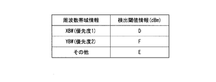
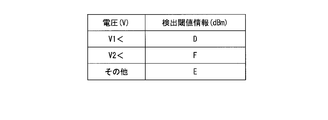
- FIG. 14 is a diagram illustrating an example of detection threshold correspondence information according to the present modification.
- the left column shows frequency band information as use environment information
- the right column shows detection threshold information.
- the second row is associated with the detection threshold D given the highest priority 1 to the frequency band information XBW
- the third row is the detection threshold given the second highest priority 2 to the frequency band information YBW.
- F is associated
- the fourth row indicates that the detection threshold E is associated with other priority information other than XBW and YBW.
- the detection threshold E is also given when the frequency band information is unknown.
- the detection threshold is lower in the order of D, F, and E.
- FIG. 15 is a flowchart showing channel selection processing according to this modification.
- the channel selection process according to this modification includes steps S141 and S142 instead of steps S101 and S102 in the channel selection process shown in FIG.
- Step S141 The detection threshold value changing unit 2141 reads the location history information stored in the memory unit 215, and extracts the frequency band information based on the read location history information.
- the detection threshold value changing unit 2141 determines the priority for each type of the extracted frequency band information. Thereafter, the process proceeds to step S142.
- the detection threshold value changing unit 2141 reads detection threshold value information corresponding to each predetermined priority from the detection threshold value correspondence information stored in the memory unit 215.
- the detection threshold value changing unit 2141 stores the detection threshold information corresponding to the other frequency band information for the frequency band excluding the frequency band indicated by the extracted frequency band information among the frequency bands that can be used by the mobile station apparatus 21. Read from 215. The detection threshold changing unit 2141 sets the detection threshold information of each available frequency band in the channel processing unit 2142. Thereafter, the process proceeds to step S103.
- FIG. 16 is a diagram illustrating an example of detection threshold information according to the present modification.
- the horizontal axis indicates the channel
- the vertical axis indicates the received signal strength.
- the frequency bands that can be used by the mobile station apparatus 21 are five frequency bands band0, band100, band200, band300, and band500.
- the ranges of channels included in each of band0, band100, band200, band300, and band500 are 0-99, 100-199, 200-200, 300-399, and 500-599.
- the in-zone history information stored in the memory unit 215 includes band0 and band200 four times and twice, respectively.
- the detection threshold value changing unit 2141 determines the priority of the band 0 and the band 200 as the priorities 1 and 2 since the frequency of the band 0 is the largest and the frequency of the band 200 is the second most frequently.
- the broken lines indicate that the detection thresholds corresponding to band 0 related to channels 0 to 99 and band 200 related to channels 200 to 299 are D and F, respectively, and detections corresponding to other channels having the lowest priority are detected.
- the threshold is E.
- the received signal strength for each channel shown in FIG. 16 is the same as the received signal strength shown in FIG.
- the detection threshold D is ⁇ 105 (dBm)
- the detection threshold F is ⁇ 100 (dBm)
- the detection threshold E is ⁇ 90 (dBm)
- the channel processing unit 2142 selects the next four channels.
- the selected channel and received signal distance pairs are (202, ⁇ 98 (dBm)), (203, ⁇ 93 (dBm)), (204, ⁇ 99 (dBm)), (222, ⁇ 85 (dBm), respectively. )).
- the detection threshold changing unit 2141 determines the detection threshold for each frequency band as the type of use environment information has been described as an example. However, in this modification, the detection threshold changing unit 2141 sets the detection threshold for each channel. It may be determined. In the above description, the case where the priority is determined based on the number of times as the usage status for each type of usage environment information has been described as an example. However, in the present modification, the detection threshold value changing unit 2141 uses the service area time, The priority may be set so as to increase as the index value indicating the usage status such as reception intensity increases. For this purpose, the detection threshold value changing unit 2141 associates the frequency band information with the area history information and stores the area time, reception intensity, and the like in the cell of the frequency band in the memory unit 215.
- the detection threshold value changing unit 2141 may set the priority so that the usage environment information of the type newly stored as the location history information, for example, the newly stored frequency band information becomes higher. In the location history information, when the same type of frequency band information is included twice or more than twice, the detection threshold value changing unit 2141 may ignore the frequency band information after the second time.
- the detection threshold changing unit 2141 mainly determines the priority for each frequency band has been described as an example.
- the detection threshold changing unit 2141 has other usage environment information such as country information and a communication operator. A priority may be set for each piece of information.
- a detection threshold is set according to the usage status for each type of usage environment information.
- a detection threshold value for detecting a received wave from the base station device is determined, and only channels having a reception level higher than the detection threshold value are determined. Select and perform synchronization processing on the received wave of the selected channel. This leaves a possibility that the minimum channel to be subjected to the synchronization process is selected, and reduces the number of selected channels. Therefore, it is possible to reduce the time and power consumption required for the synchronization process in the cell search.
- a communication system 2 (not shown) according to the present embodiment includes a mobile station device 23 instead of the mobile station device 21 in the communication system 1 (FIG. 1).
- the configuration of the mobile station apparatus 23 will be described.
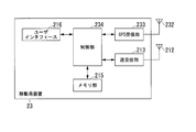
- FIG. 17 is a schematic block diagram showing the configuration of the mobile station apparatus 23 according to this embodiment.
- the mobile station device 23 includes an antenna 212, a transmission / reception unit 213, a memory unit 215, a user interface 216, a GPS (Global Positioning System) antenna 232, a GPS reception unit 233, and a control unit 234. That is, the mobile station device 23 includes a control unit 234 instead of the control unit 214 in the mobile station device 21 (FIG. 2), and further includes a GPS antenna 232 and a GPS reception unit 233.
- GPS Global Positioning System
- the GPS antenna 232 receives a position measurement signal (positioning signal) transmitted by a GPS satellite using radio waves, and outputs the received positioning signal to the GPS receiver 233 as an electrical signal.
- the GPS receiving unit 233 demodulates the positioning signal input from the GPS antenna 232, and uses the known method (for example, code positioning method) based on the demodulated positioning signal (for example, latitude, longitude). ) Is calculated.
- the GPS receiving unit 233 generates position information indicating the calculated position, and outputs the generated position information to the control unit 234. Therefore, the GPS antenna 232 and the GPS receiving unit 233 constitute a position measuring unit that measures the position of the own device.
- FIG. 18 is a schematic block diagram illustrating the configuration of the control unit 234 according to the present embodiment.
- the control unit 234 includes a detection threshold value changing unit 2341, a channel processing unit 2142, and a synchronization processing unit 2143. That is, the control unit 234 includes a detection threshold value changing unit 2341 instead of the detection threshold value changing unit 2141 in the control unit 214 (FIG. 3).
- the user interface 216 is not shown.
- the detection threshold value changing unit 2341 determines a detection threshold value based on position information input from the GPS receiving unit 233 as use environment information.
- the memory unit 215 stores in advance detection threshold correspondence information in which position information and detection threshold are associated as usage environment information. An example of detection threshold correspondence information will be described later.
- the detection threshold change unit 2341 reads detection threshold information corresponding to the input position information from the detection threshold correspondence information stored in the memory unit 215, and outputs the read detection threshold information to the channel processing unit 2142. As a result, a detection threshold is set in the channel processing unit 2142.
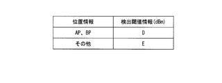
- FIG. 19 is a diagram illustrating an example of detection threshold value correspondence information according to the present embodiment.
- the left column shows position information as usage environment information
- the right column shows detection threshold information.
- the second row indicates that the detection threshold D is associated with the position information AP and BP
- the third row indicates that the detection threshold E is associated with other position information other than the AP and BP. Therefore, when the position information AP is input from the GPS receiving unit 233, the detection threshold changing unit 2341 sets the detection threshold D, and the position information (for example, CP) other than the position information AP and BP is set from the GPS receiving unit 233.
- a detection threshold E is set. Even when a positioning signal from a GPS satellite does not arrive, such as outdoors or an underground mall, the detection threshold value changing unit 2341 sets a detection threshold value E corresponding to other position information.
- the location information AP and BP are included in the area where the network that can be used by the mobile station device 21 is operated, and the detection threshold D (for example, ⁇ 105 (dBm)) is the detection threshold E (for example, ⁇ 90). Suppose the case is smaller than (dBm)). If the mobile station device 21 is located in an area where an available network is operated, for example, an AP, the mobile station device 21 is located at a position (for example, a remote location) that is difficult to reach from the base station device 11. Even so, channel selection can be made more successful from a weak received signal.
- the detection threshold D for example, ⁇ 105 (dBm)
- E for example, ⁇ 90
- a detection threshold E higher than the detection threshold D is selected.
- noise for example, ambient noise, white noise, and other received signals from the system.
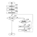
- FIG. 20 is a flowchart showing channel selection processing according to the present embodiment.
- the channel selection process shown in FIG. 20 has steps S151 and S152 instead of steps S101 and S102 in the channel selection process shown in FIG.
- the GPS receiver 233 calculates the position of the mobile station device 23 based on the positioning signal input from the GPS antenna 232, and generates position information indicating the calculated position. Thereafter, the process proceeds to step S152.
- the detection threshold value changing unit 2341 reads the detection threshold value information corresponding to the position information input from the GPS receiving unit 233 from the detection threshold value correspondence information stored in the memory unit 215, and performs channel processing on the read detection threshold value information. Part 2142. Thereafter, the process proceeds to step S103.
- the detection threshold correspondence information stored in the memory unit 215 may be associated with position information and regional frequency band information indicating a frequency band used in an area including the position. Good.
- the detection threshold value changing unit 2341 selects detection threshold value information (for example, detection threshold value D) for an area-specific frequency band (for example, 800 MHz band) related to the region including the position indicated by the input position information.
- detection threshold value information for example, detection threshold value D
- an area-specific frequency band for example, 800 MHz band
- the detection threshold value changing unit 2341 determines in advance the detection threshold value information related to the area including the position indicated by the position information.
- a detection threshold value (for example, a detection threshold value E) that is higher by a predetermined value may be determined.
- channel selection can be made more successful for the frequency band operated at the measured position. Further, for other frequency bands, it is possible to prevent erroneous selection of received signals such as noise.
- FIG. 21 is a diagram illustrating an example of received signal strength information.
- the horizontal axis indicates the channel, and the vertical axis indicates the received signal strength.
- the received signal strength shown in FIG. 21 is the same as that shown in FIG.
- the detection threshold value changing unit 2341 selects a detection threshold value E (for example, ⁇ 90 (dBm)).
- the channel processing unit 2142 selects a channel whose received signal strength is higher than the detection threshold E from the receivable channels.
- the combination of the selected channel and the reception signal distance is two channels (203, ⁇ 88 (dBm)) and (222, ⁇ 85 (dBm)).
- the detection threshold value changing unit 2341 selects a detection threshold value D (for example, ⁇ 105 (dBm)).
- the channel processing unit 2142 selects a channel whose received signal strength is higher than the detection threshold D from the receivable channels.
- the combinations of the selected channel and the received signal distance are (101, ⁇ 104 (dBm)), (202, ⁇ 98 (dBm)), (203, ⁇ 88 (dBm)), (204, ⁇ 99). (DBm)), (222, -85 (dBm)), (223, -94 (dBm)).
- the number of selected channels can be controlled by determining the detection threshold according to the position information.
- the position information is input from the GPS receiving unit 233 to the detection threshold changing unit 2341 every time a cell search is performed has been described as an example, but the present embodiment is not limited thereto.
- the GPS receiving unit 233 When the mobile station device 23 is located outside the base station device 11 for a longer time than a predetermined time, the GPS receiving unit 233 outputs position information to the detection threshold value changing unit 2341 every predetermined period. You may wait.
- the channel processing unit 2142 detects the detection threshold value determined using the position information input immediately before the next position information is output. A channel selection process is performed based on the information.
- FIG. 22 is a conceptual diagram illustrating an example of the timing of each process in the cell search.
- the horizontal axis indicates the time and indicates that four cell searches have been performed.
- the four cell searches are called cell search 1, cell search 2, cell search 3, and cell search 4 in order from the earliest cell search.
- position measurement is performed for the first cell search (cell search 1, 4,%), And for the other two times (cell search 2, 3,. No measurement is made.
- a detection threshold (for example, detection threshold E) is acquired based on the position information acquired by the position measurement in the cell search 1, and the detection acquired in each channel selection processing of the cell searches 1, 2, and 3 is performed. Each threshold is used. Further, a detection threshold (for example, detection threshold D) is acquired based on the new position information acquired by the reposition measurement in the cell search 4, and is acquired in each channel selection process of the cell searches 4, 5, and 6. Each detection threshold is used.
- FIG. 22 shows an example in which the GPS receiving unit 233 acquires and outputs position information every predetermined cell search cycle (for example, 3 times), but the GPS receiving unit 233 has a predetermined time cycle (for example, 30 times). Position information may be acquired and output every minute.
- a detection threshold based on position information, there is a possibility that the minimum channel to be subjected to synchronization processing is selected, and the number of channels to be selected. By reducing the time, the time and power consumption required for the synchronization processing can be reduced.
- the detection threshold value changing unit 2341 stores the input position information in the memory unit 215 when the position information is input from the GPS receiving unit 233.
- the detection threshold value changing unit 2341 may store the position information as part of the location history information every time input from the GPS receiving unit 233 starts.
- the detection threshold value changing unit 2341 reads the latest position information stored in the memory unit 215, and outputs the read position information to the channel processing unit 2142. Thereby, even if positioning signals from GPS satellites such as outdoors and underground shopping streets do not reach, the detection threshold value changing unit 2341 can determine the detection threshold value based on the latest position information stored in the memory unit 215.
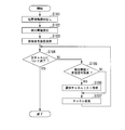
- FIG. 23 is a flowchart illustrating an example of channel selection processing according to the present modification.
- the channel selection process according to this modification includes steps S161 and S162 instead of steps S101 and S102 in the channel selection process shown in FIG. (Step S161)
- the detection threshold value changing unit 2341 stores the input position information in the memory unit 215.
- the detection threshold value changing unit 2341 reads position information stored in the memory unit 215.
- the detection threshold value changing unit 2341 extracts recent position information from the read position information. Thereafter, the process proceeds to step S162.
- Step S162 The detection threshold value changing unit 2341 reads the detection threshold value information corresponding to the position information input from the GPS receiving unit 233 or the position information read from the memory unit 215 from the detection threshold value correspondence information stored in the memory unit 215. The read detection threshold information is output to the channel processing unit 2142. Thereafter, the process proceeds to step S103.
- a detection threshold can be set based on the latest input position information. Accordingly, there is a possibility that the minimum channel to be subjected to the synchronization process is selected, and the time and power consumption required for the synchronization process can be reduced by reducing the number of selected channels.
- the detection threshold value changing unit 2341 determines the priority for each usage environment information, that is, position information, according to the usage status, and sets the detection threshold value lower as the determined priority is higher.
- the detection threshold value changing unit 2341 counts the number of times stored for each position indicated by the position information read from the memory unit 215.
- the detection threshold value change part 2341 determines the priority for every frequency band so that it may become so high that a position with many counts. For example, when the read position information AP and BP are included four or two times, the detection threshold value changing unit 2341 has a priority corresponding to the position information AP higher than a priority corresponding to the position information BP. Set priority to be higher.
- the priorities corresponding to the position information AP and BP are referred to as priorities 1 and 2, respectively.
- the detection threshold value changing unit 2341 reads detection threshold value information corresponding to the determined priority from the memory unit 215.
- the detection threshold value changing unit 2341 stores, for the frequency bands excluding the frequency band indicated by the extracted frequency band information among the frequency bands that can be used by the mobile station apparatus 21, the detection threshold information corresponding to the other frequency band information. Read from 215.
- the detection threshold value information that is stored in advance in the memory unit 215 is associated with detection threshold value information that indicates a lower detection threshold value with a higher priority.
- the other frequency band information is associated with detection threshold information indicating the highest detection threshold.
- FIG. 24 is a diagram illustrating an example of detection threshold correspondence information according to the present modification.
- the left column indicates position information as use environment information
- the right column indicates detection threshold information.
- the second row is associated with the detection threshold D given the highest priority 1 to the position information AP
- the third row is the detection threshold F given the second highest priority 2 to the position information BP.
- the fourth row indicates that the detection threshold E is associated with other priority information other than AP and BP.
- the detection threshold E is also given when the frequency band information is unknown. In this example, the detection threshold is lower in the order of D, F, and E.
- FIG. 25 is a diagram illustrating an example of detection threshold information according to the present modification.
- the horizontal axis represents the channel, and the vertical axis represents the received signal strength.
- Broken lines indicate detection thresholds E, F, and D related to priorities 1 and 2 and others.
- the received signal strength for each channel shown in FIG. 25 is the same as the received signal strength shown in FIG.
- the channel processing unit 2142 selects the next six channels.
- the selected channel and received signal distance pairs are (101, ⁇ 104 (dBm)), (202, ⁇ 98 (dBm)), (203, ⁇ 88 (dBm)), (204, ⁇ 99 (dBm), respectively. )), (222, -85 (dBm)), (223, -94 (dBm)).
- the channel processing unit 2142 selects the next three channels.
- the combinations of the selected channel and the received signal distance are (203, ⁇ 88 (dBm)), (222, ⁇ 85 (dBm)), and (223, ⁇ 94 (dBm)), respectively.
- the detection threshold E is ⁇ 90 (dBm)
- the channel processing unit 2142 selects the next two channels.
- the combinations of the selected channel and the received signal distance are (203, ⁇ 88 (dBm)) and (222, ⁇ 85 (dBm)), respectively. Therefore, since a higher detection threshold is selected in accordance with lowering the priority, the number of selected channels is reduced.
- the base station apparatus 11 since a maximum of eight synchronization processes are attempted, there is a high possibility that the base station apparatus 11 can be located in the cell 11c.
- the priority is set low and the detection threshold is set high, the number of selected channels is two, and the number of synchronization processing attempts is reduced to two. Electric power can be suppressed.
- the detection threshold value changing unit 2341 may determine the priority of the position information input from the GPS receiving unit 233 according to the distance from the base station.
- the GPS receiving unit 233 receives base station position information indicating the position of the base station apparatus 11 from a GPS satellite, and outputs the received base station position information to the detection threshold value changing unit 2341.
- the detection threshold value changing unit 2341 calculates the distance from its own device to the base station position indicated by the base station position information input from the GPS receiving unit 233.
- the detection threshold value changing unit 2341 may set a higher priority as the calculated distance is larger, and may set a lower detection threshold value. Thereby, even when the own apparatus is located in a mountain, the sea, a plain, etc., the base station apparatus 11 far from the own apparatus can be detected.
- the detection threshold changing unit 2341 sets the priority to a medium level (for example, the second stage out of three levels), that is, sets the detection threshold to a medium level. May be.
- a medium level for example, the second stage out of three levels
- the detection threshold value changing unit 2341 is estimated to be an area where there is no available base station apparatus. Of these, the lowest, that is, the detection threshold is set to the highest.
- the detection threshold is set based on the priority determined based on the use status for each piece of position information as the use environment. As a result, for position information with low priority, the detection threshold is set high, leaving the possibility that the minimum channel to be synchronized is selected and reducing the number of selected channels. It is possible to reduce the time and processing amount required for the synchronous processing.
- the position of the device itself is measured, and a detection threshold value for detecting a received wave is determined based on the measured position.
- a detection threshold value for detecting a received wave is determined based on the measured position.
- a communication system 3 (not shown) according to the present embodiment includes a mobile station device 24 instead of the mobile station device 21 in the communication system 1 (FIG. 1). Here, the configuration of the mobile station device 24 will be described.
- FIG. 26 is a schematic block diagram showing the configuration of the mobile station device 24 according to this embodiment.
- the mobile station device 24 includes an antenna 212, a transmission / reception unit 213, a memory unit 215, a user interface 216, a control unit 244, a voltage measurement unit 248, and a power source 249. That is, the mobile station device 24 includes a control unit 244 instead of the control unit 214 in the mobile station device 21 (FIG. 2), and further includes a voltage measurement unit 248 and a power source 249.
- the user interface 216 is not shown.
- the voltage measuring unit 248 measures the voltage at the positive terminal of the power source 249 and outputs voltage information indicating the measured voltage to the detection threshold value changing unit 2441 of the control unit 244.
- the voltage measurement unit 248 is, for example, an analog / digital converter (A / D converter).
- the power source 249 supplies direct current power required for operation to each of the components 212, 213, 215, 216, 244, 248, etc.
- the power source 249 is a secondary battery that can be charged and discharged, for example, a lithium ion battery.
- the power source 249 includes a positive terminal and a negative terminal. The positive terminal is connected to the voltage measuring unit 248. The negative terminal is grounded.
- FIG. 27 is a schematic block diagram illustrating the configuration of the control unit 244 according to the present embodiment.
- the control unit 244 includes a detection threshold value changing unit 2441, a channel processing unit 2142, and a synchronization processing unit 2143. That is, the control unit 244 includes a detection threshold value changing unit 2441 instead of the detection threshold value changing unit 2141 in the control unit 214 (FIG. 3).
- the detection threshold changing unit 2441 determines a detection threshold based on the voltage information input from the voltage measuring unit 248 as the usage environment information.
- the memory unit 215 stores in advance detection threshold correspondence information in which voltage information and detection threshold are associated as usage environment information. An example of detection threshold correspondence information will be described later.
- the detection threshold change unit 2441 reads detection threshold information corresponding to the input voltage information from the detection threshold correspondence information stored in the memory unit 215, and outputs the read detection threshold information to the channel processing unit 2142. As a result, a detection threshold is set in the channel processing unit 2142.
- FIG. 28 is a diagram illustrating an example of detection threshold value correspondence information according to the present embodiment.
- the left column shows voltage information as usage environment information
- the right column shows detection threshold information.
- the detection threshold D is associated with a voltage exceeding a predetermined voltage V1 (for example, 3.7V)
- the third row is a voltage equal to or lower than the other voltage, that is, the voltage V1.
- the detection threshold E is associated with. Therefore, the detection threshold value changing unit 2441 sets the detection threshold value D when voltage information indicating a voltage (for example, 4.0 V) higher than the voltage V1 is input from the voltage measurement unit 248.
- the detection threshold value changing unit 2441 sets the detection threshold value E when voltage information indicating a voltage (for example, 3.4 V) equal to or lower than the voltage V1 is input from the voltage measurement unit 248.
- a voltage sufficient for the operation of the mobile station device 24 is set in advance as the voltage V1, and the detection threshold D (for example, ⁇ 105 (dBm)) is set from the detection threshold E (for example, ⁇ 90 (dBm)). Also set it to a low value.
- the detection threshold D for example, ⁇ 105 (dBm)
- the detection threshold E for example, ⁇ 90 (dBm)
- a detection threshold D is set, and a larger number of The channel can be selected, and the possibility of successful cell search can be increased.
- FIG. 29 is a flowchart illustrating an example of channel selection processing according to the present embodiment.
- the channel selection process according to the present embodiment includes steps S171 and S172 instead of steps S101 and S102 in the channel selection process shown in FIG. (Step S ⁇ b> 171)
- the voltage measurement unit 248 measures the voltage at the positive terminal of the power source 249 and outputs voltage information indicating the measured voltage to the detection threshold value changing unit 2441. Thereafter, the process proceeds to step S172.
- the detection threshold value changing unit 2441 reads detection threshold value information corresponding to the voltage information input from the voltage measurement unit 248 from the detection threshold value correspondence information stored in the memory unit 215, and performs channel processing on the read detection threshold value information. To the unit 2142. Thereafter, the process proceeds to step S103.
- a higher detection threshold can be set in accordance with the voltage of the power supply 249, that is, the remaining amount of electric charge accumulated in the power supply 249 decreases.
- the minimum number of channels subject to synchronization processing will be selected when the remaining amount is low, and the time and power consumption for synchronization processing can be reduced by reducing the number of selected channels. Can be reduced.
- FIG. 30 is a diagram showing another example of detection threshold value correspondence information according to the present embodiment.
- the left column shows voltage information as usage environment information
- the right column shows detection threshold information.
- the second row in FIG. 30 indicates that the detection threshold D is associated when the voltage indicated by the voltage information is higher than the voltage V1.
- the third row in FIG. 30 indicates that when the voltage indicated by the voltage information is higher than the voltage V2 and equal to the voltage V1 or lower than the voltage V1, it is associated with the detection threshold F.
- the fourth row in FIG. 30 indicates that when the voltage indicated by the voltage information is equal to or lower than the voltage V2, it is associated with the detection threshold E.
- the detection threshold is a lower value in the order of D, F, and E.
- the voltage of the power supply of the device itself is measured, and the detection threshold value for detecting the received wave is determined based on the measured voltage.
- a communication system 4 (not shown) according to the present embodiment includes a mobile station device 25 instead of the mobile station device 21 in the communication system 1 (FIG. 1).
- the configuration of the mobile station apparatus 25 will be described.
- FIG. 31 is a schematic block diagram showing the configuration of the mobile station device 25 according to this embodiment.
- the mobile station apparatus 25 includes an antenna 212, a transmission / reception unit 213, a memory unit 215, a user interface 216, and a control unit 254. That is, the mobile station device 25 includes a control unit 254 instead of the control unit 214 in the mobile station device 21 (FIG. 2).
- FIG. 32 is a schematic block diagram illustrating the configuration of the control unit 254 according to the present embodiment.
- the control unit 254 includes a detection threshold value changing unit 2541, a channel processing unit 2142, and a synchronization processing unit 2143. That is, the control unit 254 includes a detection threshold value changing unit 2541 instead of the detection threshold value changing unit 2141 in the control unit 214 (FIG. 3).
- the user interface 216 is not shown.
- the detection threshold value changing unit 2541 updates the detection threshold value determined for each use environment information according to the number of repetitions of the cell search or the duration of the state where communication is not possible after the cell 11c or the like is located outside the service area. This duration is hereinafter referred to as out-of-service time.
- the detection threshold value changing unit 2541 counts the number of repetitions of the cell search performed by the synchronization processing unit 2143. Here, for example, every time step S120 (FIG. 8) ends, the detection threshold value changing unit 2541 increases the number of cell search repetitions by 1 (increment). However, the initial value of the number of repetitions of the cell search is 1.
- the detection threshold value changing unit 2541 determines the detection threshold value in the same manner as the detection threshold value changing unit 2141 (FIG. 3). However, if the number of cell search iterations is greater than 1, the detection threshold value changing unit 2541 in step S102 (FIG. 7), for example, sets a predetermined change threshold value ⁇ (for example, 5 ( dBm)). As a result, the detection threshold value decreases by ⁇ each time the number of cell search repetitions increases by one.
- the detection threshold value changing unit 2341 may repeat the process of reducing the detection threshold value until a predetermined lower limit value (for example, ⁇ 120 (dBm)) is reached or a predetermined number of repetitions (for example, 4 times). .
- the cell search is repeated without updating the area history information that the user does not move, and power may be consumed unnecessarily.
- the detection threshold according to the number of cell search repetitions and out-of-service time as in the mobile station device 25, it is possible to increase the sensitivity of the received signal and detect an effective channel.
- FIG. 33 is a diagram illustrating an example of received signal strength information.
- the horizontal axis indicates the channel, and the vertical axis indicates the received signal strength.
- E, E- ⁇ , E-2 ⁇ , and E-3 ⁇ are shown as examples of detection threshold values for the first, second, third, and fourth repetitions, respectively.
- the received signal strength for each channel shown in FIG. 33 is the same as that shown in FIG. According to FIG. 33, every time the detection threshold is lowered to E, E- ⁇ , E-2 ⁇ , E-3 ⁇ , the number of channels exceeding this detection threshold, that is, the number of selected channels is 0, 2, 2, 4 It is shown to increase.
- FIG. 34 is a diagram illustrating a modification example of the detection threshold information according to the present embodiment.
- the horizontal axis represents the number of cell search repetitions
- the vertical axis represents the detection threshold.
- the solid line indicates that the initial value of the detection threshold is E, and after the detection threshold reaches a predetermined lower limit value E-3 ⁇ (or four repetitions), the detection threshold changing unit 2541 Indicates that the threshold is maintained unchanged.
- the one-dot broken line indicates that the initial value of the detection threshold value is E, and after the detection threshold value reaches a predetermined lower limit value E-3 ⁇ (or four repetitions), the detection threshold value changing unit 2541 This indicates that the amount of increase ⁇ is increased by a predetermined amount of change every time the search is repeated. In this case, the detection threshold value changing unit 2541 may repeat the process of increasing the detection threshold value until a predetermined upper limit value (for example, the initial value E) is reached.
- a predetermined upper limit value for example, the initial value E
- the detection threshold value changing unit 2541 may set the detection threshold value for each number of repetitions so that the lower limit value is included at least once every cycle (for example, four times) of the predetermined cell search repetition number. .
- the detection threshold value is set to E in the first and second times out of the cycle of 3 repetitions as indicated by +, and the detection threshold value is E-3 ⁇ in the third time. It is determined.
- the detection threshold value changing unit 2341 may randomly determine the number of repetitions that determines the detection threshold value as the lower limit value with a predetermined probability (for example, 1 ⁇ 4). As a result, the processing time and power consumption can be saved as a whole, and the possibility that the channel is detected reliably can be ensured.
- the detection threshold value changing unit 2541 changes the detection threshold value for each number of cell searches has been described as an example.
- the out-of-service time is a multiple of a predetermined time interval (for example, 10 minutes) instead of the number of times.
- the detection threshold may be changed. For example, when the detection threshold value is set to E when the detection threshold value changing unit 2541 goes out of the range of the cell 11c, as shown by a solid line in FIG. 34, 10 minutes, 20 minutes, 30 minutes, 40 minutes, 50 After elapse of minutes, 60 minutes, and 70 minutes, the detection threshold values may be determined as E- ⁇ , E-2 ⁇ , E-3 ⁇ , E-3 ⁇ , E-3 ⁇ , and E-3 ⁇ , respectively. Further, the detection threshold value changing unit 2541 may set the detection threshold value at a predetermined time interval as indicated by a one-dot broken line or a + mark in FIG.
- the detection threshold value changing unit 2541 changes the detection threshold value over the entire band according to the number of cell searches and the out-of-service time
- the detection threshold may be changed for a frequency band indicated by a predetermined frequency band or frequency band information included in the location history information.
- the detection threshold value changing unit 2541 includes a configuration in which the detection threshold value changing unit 2141 (FIG. 3) updates the detection threshold value determined for each use environment information according to the number of cell search repetitions or out-of-service time. Although described as an example, the present embodiment is not limited to this.
- the detection threshold value changing unit 2541 updates the detection threshold value determined for each use environment information according to the number of cell search repetitions described above in the detection threshold value changing units 2341 (FIG. 18) and 2441 (FIG. 27) or out-of-service time. May be provided.
- the detection threshold value correspondence information used by the detection threshold value changing units 2141 (FIG. 3), 2341 (FIG. 18), 2441 (FIG. 27), and 2541 (FIG. 32) to determine the detection threshold value is 2
- the detection threshold value information may include detection threshold information indicating each of more than three stages, for example, four stages of detection thresholds.
- a detection threshold value changing unit for determining a detection threshold value for detecting a received wave from a base station device based on usage environment information indicating a usage environment of the own device, and receiving from the channel constituting the received wave from the detection threshold value
- a mobile station apparatus comprising: a channel selection unit that selects a channel having a high level; and a synchronization processing unit that performs a synchronization process on a received wave of a channel selected by the channel selection unit.
- the usage environment information includes country information of a region where a network connected to the base station apparatus is operated, and the detection threshold value changing unit changes the detection threshold value based on the country information.
- Mobile station device includes country information of a region where a network connected to the base station apparatus is operated, and the detection threshold value changing unit changes the detection threshold value based on the country information.
- the usage environment information includes business operator information of a business operator operating a network connected to the base station apparatus, and the detection threshold value changing unit changes the detection threshold value based on the business operator information (1 ) Mobile station device.
- the usage environment information includes frequency band information indicating a frequency band operated in a network connected to the base station apparatus, and the detection threshold value changing unit changes the detection threshold value based on the frequency band information.
- a voltage measurement unit that measures the voltage of the power supply of the device itself is included, the voltage information indicating the voltage measured by the voltage measurement unit is included as the use environment information, and the detection threshold value changing unit is based on the voltage information (1)
- the mobile station apparatus that changes the detection threshold.
- a storage unit that stores history information that is a history of the usage environment information, and the history information includes a plurality of types of usage environment information, and the detection threshold value changing unit includes each of the plurality of types.
- the detection threshold value changing unit changes the detection threshold value according to the number of times the synchronization processing unit repeats the synchronization process or the duration after being outside the area where radio waves reach from the base station device ( The mobile station apparatus according to any one of 1) to (7).
- the detection threshold value changing unit selects one detection threshold value from at least two predetermined detection threshold candidates according to the use environment information. (1) to (8) apparatus.
- a communication method in a mobile station apparatus wherein a detection threshold value changing process for changing a detection threshold value for detecting a received wave from a base station apparatus based on usage environment information indicating a usage environment of the mobile station apparatus,
- a communication method comprising: a channel selection process for selecting a channel having a reception level higher than the detection threshold from the channels constituting the reception wave; and a synchronization processing process for performing a synchronization process on the reception wave of the channel selected in the channel selection process.
- a detection threshold changing procedure for changing a detection threshold for detecting a received wave from a base station device based on usage environment information indicating a usage environment of the mobile station device, and configuring the received wave in a computer of the mobile station device
- a communication program for executing a channel selection procedure for selecting a channel having a reception level higher than the detection threshold from the channels to be performed, and a synchronization processing procedure for performing a synchronization process on the received wave of the channel selected in the channel selection procedure.
- the number of channels selected as a target for synchronization processing is reduced according to the use environment of the own device, and the minimum number of channels Is selected. Therefore, the possibility of resuming communication can be ensured, and the processing time and power consumption required for the synchronization process in the cell search can be reduced.
- the number of selected channels is reduced according to the country in which the network is operated in (1).
- the number of selected channels is reduced according to the operator operating the network in (1).
- the number of selected channels is reduced according to the frequency band operated in the network in (1).
- the number of channels selected in (1) is reduced according to the position of the own apparatus.
- the number of channels selected in (1) is reduced according to the voltage of the power supply of the own device.
- the number of channels selected in any one of (1) to (6) is reduced according to the usage status of each of the plurality of types of usage environments.
- the channel selected in any one of (1) to (7) in accordance with the number of repetitions of the synchronization processing and the duration after being outside the service area where the radio wave from the base station device reaches The number is reduced.
- the channel which comprises a received wave with the sensitivity selected according to the use environment of the own apparatus in any of (1) to (8) is selected.
- control part 214,234,244,254 with a computer.
- the program for realizing the control function may be recorded on a computer-readable recording medium, and the program recorded on the recording medium may be read by the computer system and executed.
- the “computer system” is a computer system built in the mobile station apparatuses 21, 22, 23, 24, 25, and includes an OS and hardware such as peripheral devices.
- the “computer-readable recording medium” refers to a storage device such as a flexible medium, a magneto-optical disk, a portable medium such as a ROM or a CD-ROM, and a hard disk incorporated in a computer system.
- the “computer-readable recording medium” is a medium that dynamically holds a program for a short time, such as a communication line when transmitting a program via a network such as the Internet or a communication line such as a telephone line,
- a volatile memory inside a computer system that serves as a server or a client may be included that holds a program for a certain period of time.
- the program may be a program for realizing a part of the functions described above, and may be a program capable of realizing the functions described above in combination with a program already recorded in a computer system.
- Each of the functional blocks 21, 22, 23, 24, and 25 may be individually made into a processor, or a part or all of them may be integrated into a processor. Further, the method of circuit integration is not limited to LSI, and may be realized by a dedicated circuit or a general-purpose processor. In addition, when an integrated circuit technology that replaces LSI appears due to the advancement of semiconductor technology, an integrated circuit based on the technology may be used.
- the integrated circuit includes at least a part of the user interface 216 described above, that is, any one of the sound reproduction unit, the sound collection unit, the image display unit, the imaging unit, and the operation input unit, or any combination thereof, or Not all of them need to be included.
- the present invention can be applied to a mobile station apparatus, an integrated circuit, a communication method, a communication program, and the like that need to reduce processing time and power consumption related to cell search.
Landscapes
- Engineering & Computer Science (AREA)
- Computer Networks & Wireless Communication (AREA)
- Signal Processing (AREA)
- Computer Security & Cryptography (AREA)
- Quality & Reliability (AREA)
- Mobile Radio Communication Systems (AREA)
Abstract
検出閾値変更部は自装置の使用環境を示す使用環境情報に基づいて、基地局装置から受信波を検出する検出閾値を変更し、チャネル選択部は前記受信波を構成するチャネルから前記検出閾値よりも受信レベルが高いチャネルを選択し、同期処理部は前記チャネル選択部が選択したチャネルの受信波について同期処理を行う。これによりセルサーチに係る処理時間や消費電力を低減する。
Description
本発明は、移動局装置、集積回路、通信方法及び通信プログラムに関する。
本願は、2013年2月15日に、日本に出願された特願2013-028189号に基づき優先権を主張し、その内容をここに援用する。
本願は、2013年2月15日に、日本に出願された特願2013-028189号に基づき優先権を主張し、その内容をここに援用する。
携帯電話等の無線通信の普及により、有限の周波数資源をできるだけ多くのユーザが活用することが求められている。携帯電話に係る無線通信システムでは、主に、複数の基地局装置が相互に有線で接続される。また、基地局装置は、ユーザが用いる移動局装置と無線で接続される。従って、無線通信システムで通信できる領域は、それぞれの基地局装置から電波が届く範囲(セル)に限られるが、複数の基地局装置を異なる位置に配置することで広範な場所で通信を行うことが可能になる。また、運用されている国、事業者、通信サービス等によって異なるセル配置や周波数帯域の無線通信システムが用いられることがある。
他方、移動局装置は、基地局装置から電波が届く領域(セル)の範囲外(圏外)に移動することがある。移動局装置は、圏外において通信を行える状態にするために通信が可能な基地局装置を探索する処理(セルサーチ)を行う。セルサーチは、主に受信強度の測定と同期処理とからなる。セルサーチが成功した後で他の移動局装置との通信が可能になる。
圏外でのセルサーチ(例えば、日本から欧州に移動したときのセルサーチ)においては、一般に、移動局装置は、利用可能な通信システムで受信可能な全チャネルに対して受信強度を測定し、次いで同期処理を行う。そのため、セルサーチには長時間を要し、また消費電力が増大するとの欠点があった。
圏外でのセルサーチ(例えば、日本から欧州に移動したときのセルサーチ)においては、一般に、移動局装置は、利用可能な通信システムで受信可能な全チャネルに対して受信強度を測定し、次いで同期処理を行う。そのため、セルサーチには長時間を要し、また消費電力が増大するとの欠点があった。
そこで、特許文献1に記載の通信方法では、(1)通信システムA、Bで利用可能な移動局装置が、いずれの通信システムについても圏外である場合に、従来どおりのセルサーチ(全チャネルに対するセルサーチ)を行うことを計画し、(2)その途中で、例えば、システムAの基地局を発見すると、報知情報から国番号(MCC:Mobile Country Code)を取得し、本体内記憶部及び外部記憶部のリストから国情報とオペレータの組み合わせが一致する周波数が当該リストに記憶されているか否かを検索し、(3)例えば、システムBについて記憶されていれば、サーチ対象の周波数に対してセルサーチを実施する。システムBが記憶されていない場合には、セルサーチを実施しない。このように、セルサーチに先行して、サーチ対象の周波数をその国で通信サービスを提供しているオペレータの周波数に限定し、通信サービスを提供していないオペレータの報知情報まで取得しようとする無用なセルサーチを省略する。
特許文献1の通信方法では、携帯電話機等の移動局装置が利用可能な周波数帯域であっても、セルサーチが制限されることがある。例えば、運用されている周波数帯域が、ある時点でセルサーチが制限されている周波数帯域に変更された場合には、セルサーチが行われず通信を行うことができなくなるという問題がある。また、特許文献1の通信方法では、移動局装置は、記憶した履歴情報でセルサーチを行うと判断した場合に、運用されていない周波数帯域のノイズや微弱な妨害波等による多数の受信波を検出して、無用な同期処理を行うという問題がある。
本発明は、上記の点に鑑みてなされたものであり、セルサーチに係る処理時間や消費電力を低減する移動局装置、集積回路、通信方法及び通信プログラムを提供する。
本発明は上記の課題を解決するためになされたものであり、本発明の一態様は、自装置の使用環境を示す使用環境情報に基づいて、基地局装置から受信波を検出する検出閾値を変更する検出閾値変更部と、前記受信波を構成するチャネルから前記検出閾値よりも受信レベルが高いチャネルを選択するチャネル選択部と、前記チャネル選択部が選択したチャネルの受信波について同期処理を行う同期処理部と、を備える移動局装置である。
本発明の各態様によれば、セルサーチに係る処理時間や消費電力を低減することができる。
(第1の実施形態)
以下、図面を参照しながら本発明の実施形態について説明する。
図1は、本実施形態に係る通信システム1を示す概念図である。
通信システム1は、複数個(図1に示す例では、2個)の基地局装置11、12及び複数個(図1に示す例では、2個)の移動局装置21、22を含んで構成される。
以下、図面を参照しながら本発明の実施形態について説明する。
図1は、本実施形態に係る通信システム1を示す概念図である。
通信システム1は、複数個(図1に示す例では、2個)の基地局装置11、12及び複数個(図1に示す例では、2個)の移動局装置21、22を含んで構成される。
基地局装置11、12は、基幹網(CN:Core Network、図示せず)とセル11c、12cに在圏している移動局装置21、22との間で電波を用いて信号を送信及び受信する装置である。基地局装置11、12は、eNB(evolved Node B)と略称されることがある。セル11c、12cは、それぞれ基地局装置11、12が電波を用いて移動局装置21、22との間で信号を送信及び受信することができる領域(エリア)である。基地局装置11、12のそれぞれは、それぞれ異なる位置に配置される。
基地局装置11、12は、大規模基地局装置(マクロセル)でも小型基地局装置(例えば、マイクロセル、ピコセル、フェムトセル)のいずれでもよい。マクロセルは、半径が数百m程度~数km程度のセル11c、12c、またはそのセルを有する基地局装置である。マイクロセルは、半径が数十m程度~数百m程度のセル11c、12c、またはそのセルを有する基地局装置である。ピコセルは、半径が数m程度~数十m程度のセル11c、12c、またはそのセルを有する基地局装置である。フェムトセルは、半径が数m以下のセル11c、12c、またはそのセルを有する基地局装置である。フェムトセルは、ホーム基地局装置(HeNB:Home eNodeB)とも呼ばれる。従って、1つのネットワークに接続されたセル11c、12c等が、そのネットワークで通信を行うことができるサービスエリアを形成する。
基地局装置11、12等に接続されるネットワークは、例えば、PLMN(Public Land Mobile Network、公衆無線通信網)である。PLMNは、通信事業者がユーザ(加入者)に通信サービスを提供するネットワークである。採用されている通信方式、周波数帯域、接続されている基地局装置11、12等は、運用されている国、事業者によって異なることがある。通信方式は、例えば、LTE(Long Term Evolution)、LTE-A(LTE-Advanced)、W-CDMA(Wideband Code Division Multiple Access)、GSM(登録商標)(Global System for Mobile Communications)等である。
移動局装置21、22は、それぞれ基地局装置11、12のいずれかを介して電波で信号を送信及び受信することによって、通信相手との通信を実現する装置である。移動局装置21、22は、端末装置、ユーザ装置(UE:User Equipment)とも呼ばれる。移動局装置21、22は、例えば、携帯電話機、多機能携帯電話機(いわゆるスマートフォンを含む)、タブレット端末装置、等である。
サービスエリアは、図1に示すように、空間全体を占めるとは限らない。基地局装置11、12の配置、それらの電波の出力、建造物その他の障害物の配置、ノイズ源等により、基地局装置11、12からの信号を移動局装置21、22が受信できないことがある。
移動局装置21を起点とする矢印は、移動局装置21は、セル11cに属す位置にあったが、その後、セル11cを含むサービスエリア外(圏外)に移動したことを示す。他方、移動局装置22を起点とする矢印は、移動局装置21は当初セル11cに属す位置にあったが、順次、圏外、セル12c、圏外と移動したことを示す。移動局装置21、22は、起動時や、一度圏外に所在して通信できない状態になった場合に、自装置が属する(在圏)するセルに係る基地局装置11、12を探索(セルサーチ)する。探索が成功することによって、移動局装置21、22は、基地局装置11、12と通信できる状態になる。
移動局装置21を起点とする矢印は、移動局装置21は、セル11cに属す位置にあったが、その後、セル11cを含むサービスエリア外(圏外)に移動したことを示す。他方、移動局装置22を起点とする矢印は、移動局装置21は当初セル11cに属す位置にあったが、順次、圏外、セル12c、圏外と移動したことを示す。移動局装置21、22は、起動時や、一度圏外に所在して通信できない状態になった場合に、自装置が属する(在圏)するセルに係る基地局装置11、12を探索(セルサーチ)する。探索が成功することによって、移動局装置21、22は、基地局装置11、12と通信できる状態になる。
(移動局装置の構成)
次に、本実施形態に係る移動局装置21の構成について説明する。移動局装置22は、移動局装置21と同様な構成を有するため、移動局装置21の説明を援用する。以下の説明では、移動局装置21は、主に基地局装置11を用いて通信を行う場合を例にとるが、本実施形態ではこれに限られず、移動局装置21は、その他の基地局装置、例えば、基地局装置12を用いてもよい。
次に、本実施形態に係る移動局装置21の構成について説明する。移動局装置22は、移動局装置21と同様な構成を有するため、移動局装置21の説明を援用する。以下の説明では、移動局装置21は、主に基地局装置11を用いて通信を行う場合を例にとるが、本実施形態ではこれに限られず、移動局装置21は、その他の基地局装置、例えば、基地局装置12を用いてもよい。
図2は、本実施形態に係る移動局装置21の構成を示す概略ブロック図である。
移動局装置21は、アンテナ212、送受信部213、制御部214、メモリ部(記憶部)215及びユーザインタフェース216を含んで構成される。
アンテナ212は、基地局装置11からの受信波、即ち電波で到達した無線周波数帯域の受信信号を受信し、その受信信号を送受信部213に出力する。アンテナ212は、送受信部213から入力された無線周波数帯域の送信信号を電波で基地局装置11に送信する。
移動局装置21は、アンテナ212、送受信部213、制御部214、メモリ部(記憶部)215及びユーザインタフェース216を含んで構成される。
アンテナ212は、基地局装置11からの受信波、即ち電波で到達した無線周波数帯域の受信信号を受信し、その受信信号を送受信部213に出力する。アンテナ212は、送受信部213から入力された無線周波数帯域の送信信号を電波で基地局装置11に送信する。
送受信部213は、アンテナ212から入力された無線周波数帯域の受信信号を基底周波数帯域の受信信号に変換し、変換した受信信号を制御部214に出力する。送受信部213は、制御部214から入力された基底周波数帯域の送信信号を無線周波数帯域に変換し、変換した送信信号をアンテナ212に出力する。
また、送受信部213は、基地局装置11から受信した受信レベル(受信信号強度、RSSI:Received Signal Strength Indicator)をチャネル毎に測定する。送受信部213は、チャネル毎に測定した受信信号強度を示す受信信号強度情報を制御部214に出力する。ここで、チャネルとは、通信に用いられる電波を構成する周波数または周波数帯域であって、データを割り当てる単位となる周波数または周波数帯域である。例えば、GSM(登録商標)方式では、各チャネルは、200kHz間隔で配置されている。また、LTE方式では、チャネルは、サブキャリアとも呼ばれ、1チャネル当たりの帯域幅は15kHzである。LTE方式では、移動局装置21と基地局装置11との間の通信では、複数(例えば、帯域幅が10MHzの場合、約600個)のチャネルが用いられる。
なお、受信レベルの指標として、以下の説明では主に受信信号強度(RSSI)を用いる場合を例にとるが、本実施形態では、RSRP(基準信号受信パワー:Reference Signal Received Power)やRSRQ(基準信号受信品質:Reference Signal Recieved Quality)などの受信レベルの指標を利用してもよい。
また、送受信部213は、基地局装置11から受信した受信レベル(受信信号強度、RSSI:Received Signal Strength Indicator)をチャネル毎に測定する。送受信部213は、チャネル毎に測定した受信信号強度を示す受信信号強度情報を制御部214に出力する。ここで、チャネルとは、通信に用いられる電波を構成する周波数または周波数帯域であって、データを割り当てる単位となる周波数または周波数帯域である。例えば、GSM(登録商標)方式では、各チャネルは、200kHz間隔で配置されている。また、LTE方式では、チャネルは、サブキャリアとも呼ばれ、1チャネル当たりの帯域幅は15kHzである。LTE方式では、移動局装置21と基地局装置11との間の通信では、複数(例えば、帯域幅が10MHzの場合、約600個)のチャネルが用いられる。
なお、受信レベルの指標として、以下の説明では主に受信信号強度(RSSI)を用いる場合を例にとるが、本実施形態では、RSRP(基準信号受信パワー:Reference Signal Received Power)やRSRQ(基準信号受信品質:Reference Signal Recieved Quality)などの受信レベルの指標を利用してもよい。
制御部214は、移動局装置21が行う処理を制御する。制御部214は、例えば、送受信部213からの受信信号の入力や、送受信部213への送信信号の出力を制御する。
制御部214は、送受信部213から入力された受信信号のうちユーザデータをユーザインタフェース216に出力し、ユーザインタフェース216から入力されたユーザデータを送受信部213に送信信号として出力する。ここで、ユーザデータとは、通信相手先である移動局装置22との間で送信又は受信される信号、例えば、音声信号、映像信号、テキストデータ等である。
制御部214は、ユーザインタフェース216から入力された操作入力信号に応じて、処理の開始、停止、態様の変更等を制御し、取得した画像信号や文字信号等をユーザインタフェース216に出力する。制御部214は、メモリ部215から読み出したデータの処理を行う際に用いることがある。また、制御部214は、処理において生成したデータをメモリ部215に記憶する。制御部214は、例えば、受信可能な周波数帯域の全帯域において、受信信号強度が予め定めた検出閾値(例えば、-120(dBm))と等しいか、その検出閾値よりも低い場合、圏外に所在していると判定する。制御部214は、受信信号強度が、その検出閾値を超える場合、セル11cの圏内に所在していると判定する。制御部214のより詳細な構成については後述する。
制御部214は、送受信部213から入力された受信信号のうちユーザデータをユーザインタフェース216に出力し、ユーザインタフェース216から入力されたユーザデータを送受信部213に送信信号として出力する。ここで、ユーザデータとは、通信相手先である移動局装置22との間で送信又は受信される信号、例えば、音声信号、映像信号、テキストデータ等である。
制御部214は、ユーザインタフェース216から入力された操作入力信号に応じて、処理の開始、停止、態様の変更等を制御し、取得した画像信号や文字信号等をユーザインタフェース216に出力する。制御部214は、メモリ部215から読み出したデータの処理を行う際に用いることがある。また、制御部214は、処理において生成したデータをメモリ部215に記憶する。制御部214は、例えば、受信可能な周波数帯域の全帯域において、受信信号強度が予め定めた検出閾値(例えば、-120(dBm))と等しいか、その検出閾値よりも低い場合、圏外に所在していると判定する。制御部214は、受信信号強度が、その検出閾値を超える場合、セル11cの圏内に所在していると判定する。制御部214のより詳細な構成については後述する。
メモリ部215には、制御部214が行う処理に用いるデータ、例えば、受信信号の周波数帯域を検出するために用いる検出閾値を示す検出閾値情報を予め記憶しておく。また、制御部214が取得したデータを記憶する。以下の説明では、検出閾値情報を単に検出閾値と呼ぶことがある。
ユーザインタフェース216は、ユーザに制御部214から入力された受信信号に応じた情報を提示し、ユーザから受け付けた情報を制御部214に出力する。
ユーザインタフェース216は、例えば、制御部214から入力された音声信号に応じた音声を音声再生部(例えば、スピーカ、図示せず)に再生させ、収音部(例えば、マイクロホン、図示せず)で収録した音声の音声信号を制御部214に出力する。
また、ユーザインタフェース216は、制御部214から入力された画像信号が示す画像を画像表示部(例えば、ディスプレイ、図示せず)に表示させ、及び撮像部(例えば、カメラ、図示せず)が撮像した画像を示す画像信号を制御部214に出力する。
ユーザインタフェース216は、操作入力部(例えば、タッチセンサ、図示せず)が検出したユーザの操作入力に応じた操作入力信号を制御部214に出力する。操作入力部と画像表示部は、それらが一体化して構成されたタッチパネルであってもよい。また、音声再生部、収音部、画像表示部、撮像部及び操作入力部の一部又は全部は、移動局装置21と一体化されていてもよいし、別体であってもよい。
ユーザインタフェース216は、ユーザに制御部214から入力された受信信号に応じた情報を提示し、ユーザから受け付けた情報を制御部214に出力する。
ユーザインタフェース216は、例えば、制御部214から入力された音声信号に応じた音声を音声再生部(例えば、スピーカ、図示せず)に再生させ、収音部(例えば、マイクロホン、図示せず)で収録した音声の音声信号を制御部214に出力する。
また、ユーザインタフェース216は、制御部214から入力された画像信号が示す画像を画像表示部(例えば、ディスプレイ、図示せず)に表示させ、及び撮像部(例えば、カメラ、図示せず)が撮像した画像を示す画像信号を制御部214に出力する。
ユーザインタフェース216は、操作入力部(例えば、タッチセンサ、図示せず)が検出したユーザの操作入力に応じた操作入力信号を制御部214に出力する。操作入力部と画像表示部は、それらが一体化して構成されたタッチパネルであってもよい。また、音声再生部、収音部、画像表示部、撮像部及び操作入力部の一部又は全部は、移動局装置21と一体化されていてもよいし、別体であってもよい。
(制御部の構成)
次に、本実施形態に係る制御部214の構成について説明する。
図3は、本実施形態に係る制御部214の構成を示す概略ブロック図を示す。
制御部214は、検出閾値変更部2141、チャネル処理部(チャネル選択部)2142及び同期処理部2143を含んで構成される。図3では、ユーザインタフェース216の図示が省略されている。
次に、本実施形態に係る制御部214の構成について説明する。
図3は、本実施形態に係る制御部214の構成を示す概略ブロック図を示す。
制御部214は、検出閾値変更部2141、チャネル処理部(チャネル選択部)2142及び同期処理部2143を含んで構成される。図3では、ユーザインタフェース216の図示が省略されている。
検出閾値変更部2141は、移動局装置21の使用環境を示す使用環境情報に基づいて、基地局装置11から受信した受信信号の周波数帯域(チャネル)を検出する検出閾値を定める。ここで、検出閾値変更部2141は、例えば、在圏履歴情報をメモリ部215から読み出し、読み出した在圏履歴情報のうち最近の在圏履歴情報から国情報を抽出する。
在圏履歴情報は、移動局装置21が属するセルに係る基地局装置11や、基地局装置11に接続されたネットワークの履歴を示す情報である。在圏履歴情報には、国情報の他、通信オペレータ情報、周波数帯域情報、が含まれる。在圏履歴情報は、報知情報(後述)に含まれる情報である。
在圏履歴情報は、移動局装置21が属するセルに係る基地局装置11や、基地局装置11に接続されたネットワークの履歴を示す情報である。在圏履歴情報には、国情報の他、通信オペレータ情報、周波数帯域情報、が含まれる。在圏履歴情報は、報知情報(後述)に含まれる情報である。
検出閾値変更部2141は、抽出した国情報に対応する検出閾値情報をメモリ部215に記憶されている検出閾値対応情報から読み出し、読み出した検出閾値情報をチャネル処理部2142に出力する。これにより、チャネル処理部2142に設定される検出閾値が変更される。検出閾値対応情報は、使用環境情報として国情報と検出閾値が対応付けられた情報である。検出閾値対応情報の例については、後述する。
チャネル処理部2142は、基地局装置11からの受信信号から検出閾値変更部2141から入力された検出閾値情報が示す検出閾値よりも強度が高いチャネルを選択する。ここで、チャネル処理部2142には、送受信部213から受信信号強度情報がチャネル毎に入力され、検出閾値変更部2141から入力された検出閾値情報が示す検出閾値と比較する。チャネル処理部2142は、入力された受信信号強度情報が示す受信信号強度が入力された検出閾値情報が示す検出閾値よりも大きいチャネルを選択する。チャネル処理部2142は、選択したチャネルを示すチャネル選択情報を同期処理部2143に出力する。チャネル選択処理の例については、後述する。
また、チャネル処理部2142は、セルサーチ(後述)が終了した直後、基地局装置11からの受信信号として送受信部213から報知情報が入力され、入力された報知情報から在圏履歴情報を抽出する。チャネル処理部2142は、抽出した在圏履歴情報をメモリ部215に記憶してもよい。また、チャネル処理部2142は、同期処理部2143が同期処理(後述)で復調した報知情報から在圏履歴情報を抽出し、抽出した在圏履歴情報をメモリ部215に記憶してもよい。
また、チャネル処理部2142は、セルサーチ(後述)が終了した直後、基地局装置11からの受信信号として送受信部213から報知情報が入力され、入力された報知情報から在圏履歴情報を抽出する。チャネル処理部2142は、抽出した在圏履歴情報をメモリ部215に記憶してもよい。また、チャネル処理部2142は、同期処理部2143が同期処理(後述)で復調した報知情報から在圏履歴情報を抽出し、抽出した在圏履歴情報をメモリ部215に記憶してもよい。
同期処理部2143は、チャネル処理部2142から入力されたチャネル選択情報が示すチャネルの受信波について同期処理を行う。ここで、同期処理部2143には、チャネル処理部2142からチャネル選択情報が入力され、基地局装置11からの受信信号として送受信部213からチャネル毎に変調された報知情報が入力される。同期処理部2143は、入力されたチャネル選択情報が示すチャネル毎に入力された報知情報に含まれる同期信号を検出する。同期処理部2143は、検出した同期信号を用いて報知情報が構成されているデータを特定し、特定したデータから報知情報を復調(デコード)する。同期処理部2143は、同期信号の検出、報知情報の復調がともに成功したチャネル(利用可能チャネル)が検知されるまで、それらの処理を試行する。同期処理部2143は、位置登録要求信号を基地局装置11への利用可能チャネルを用いた送信信号として送受信部213に出力する(キャンプオン)。位置登録要求信号とは、自装置を通信に用いる移動局装置として登録することを要求する信号である。その後、送受信部213は位置登録完了信号と在圏履歴情報を基地局装置11から受信することで、移動局装置21は通信できる状態になる。同期処理の例については後述する。このような、チャネル処理部2142が行うチャネル選択処理と、同期処理部2143が行う同期処理の両者は、あわせてセルサーチと呼ばれる。
(検出閾値対応情報の例)
次に、本実施形態に係る検出閾値対応情報の例について説明する。
図4は、本実施形態に係る検出閾値対応情報の例を示す図である。
図4において、左列は使用環境情報として国情報を示し、右列は検出閾値情報を示す。
第2行は、国情報AC、BCに検出閾値Dが対応付けられ、第3行は、AC、BC以外のその他の国情報に検出閾値Eが対応付けられることを示す。従って、検出閾値変更部2141は、在圏履歴情報から国情報ACが抽出された場合、検出閾値Dを設定し、在圏履歴情報からAC、BC以外の国情報(例えば、国情報CC)が抽出された場合、検出閾値Eを設定する。移動局装置21の出荷直後等、在圏履歴情報が記憶されていない場合にも、検出閾値変更部2141は、検出閾値Eを設定する。
次に、本実施形態に係る検出閾値対応情報の例について説明する。
図4は、本実施形態に係る検出閾値対応情報の例を示す図である。
図4において、左列は使用環境情報として国情報を示し、右列は検出閾値情報を示す。
第2行は、国情報AC、BCに検出閾値Dが対応付けられ、第3行は、AC、BC以外のその他の国情報に検出閾値Eが対応付けられることを示す。従って、検出閾値変更部2141は、在圏履歴情報から国情報ACが抽出された場合、検出閾値Dを設定し、在圏履歴情報からAC、BC以外の国情報(例えば、国情報CC)が抽出された場合、検出閾値Eを設定する。移動局装置21の出荷直後等、在圏履歴情報が記憶されていない場合にも、検出閾値変更部2141は、検出閾値Eを設定する。
ここで、国情報AC、BCが、移動局装置21が利用可能なネットワークを運用している国を示すときであって、検出閾値D(例えば、-105(dBm))は検出閾値E(例えば、-90(dBm))よりも小さい。
利用可能なネットワークを運用している国に移動局装置21が在圏した後で、圏外に移動したときでも、検出閾値Eよりも低い検出閾値Dが選択される。
これにより、移動局装置21が基地局装置11から電波が到達しない位置、又は到達が困難な位置(例えば、遠隔地)に所在していても、微弱な受信信号から、より確実にチャネル選択を成功させることができる。
他方、国情報CCが示す国のように利用可能なネットワークを運用していない国で移動局装置21が動作しているとき、検出閾値Dよりも高い検出閾値Eが選択される。これにより、移動局装置21がノイズ、例えば、周囲のノイズ、ホワイトノイズ、その他のシステムからの微弱な受信信号を誤って選択することを防ぐことができる。
利用可能なネットワークを運用している国に移動局装置21が在圏した後で、圏外に移動したときでも、検出閾値Eよりも低い検出閾値Dが選択される。
これにより、移動局装置21が基地局装置11から電波が到達しない位置、又は到達が困難な位置(例えば、遠隔地)に所在していても、微弱な受信信号から、より確実にチャネル選択を成功させることができる。
他方、国情報CCが示す国のように利用可能なネットワークを運用していない国で移動局装置21が動作しているとき、検出閾値Dよりも高い検出閾値Eが選択される。これにより、移動局装置21がノイズ、例えば、周囲のノイズ、ホワイトノイズ、その他のシステムからの微弱な受信信号を誤って選択することを防ぐことができる。
なお、本実施形態では、メモリ部215に記憶される検出閾値対応情報は、国情報とその国で利用されている周波数帯域を示す国別周波数帯域情報とが対応付けられていてもよい。その場合、検出閾値変更部2141は、在圏履歴情報から抽出した国情報に対応する国別周波数帯域(例えば、800MHz帯、900MHz帯)について検出閾値情報(例えば、検出閾値D)を選択する。その他の移動局装置21が利用可能な周波数帯域(例えば、1800MHz帯、1900MHz帯)については、検出閾値変更部2141は、国別周波数帯域についての検出閾値情報よりも予め定めた値だけ高い検出閾値(例えば、検出閾値E)を定める。
これにより、その国で利用されている周波数帯域については、より確実にチャネル検出を成功させることができる。また、その他の周波数帯域については、ノイズ等の受信信号を誤って検出することを防ぐことができる。
これにより、その国で利用されている周波数帯域については、より確実にチャネル検出を成功させることができる。また、その他の周波数帯域については、ノイズ等の受信信号を誤って検出することを防ぐことができる。
(在圏履歴情報の例)
次に、本実施形態に係る在圏履歴情報の例について説明する。
図5は、本実施形態に係る在圏履歴情報の例を示す図である。
図5に示す在圏履歴情報は、移動局装置22(図1)が基地局装置11のセル11cに属する位置から、その圏外を経て、セル12cの圏内に移動したときに得られたものである。
次に、本実施形態に係る在圏履歴情報の例について説明する。
図5は、本実施形態に係る在圏履歴情報の例を示す図である。
図5に示す在圏履歴情報は、移動局装置22(図1)が基地局装置11のセル11cに属する位置から、その圏外を経て、セル12cの圏内に移動したときに得られたものである。
図5において、最左列から右側へ順に、基地局情報、国情報、通信オペレータ情報、周波数帯域情報を示す。基地局情報は、移動局装置22が在圏している基地局装置を示す情報を示す。国情報は、その基地局装置に接続されるネットワークが運用される地域である国を示す情報(MCC:Mobile Country Code)を示す。通信オペレータ情報は、その基地局装置に接続されるネットワークを運用するオペレータ(事業者)を示す情報(MNC:Mobile Network Code)を示す。MCCとMNCの組み合わせは、PLMN識別情報(PLMN Identity)である。周波数帯域情報は、その基地局装置に接続されるネットワークが運用される周波数帯域、つまりその基地局装置が利用可能な周波数帯域を示す情報である。これらは、BCCH(Broadcast Control Channel、報知制御チャネル)に割り当てられて受信した報知情報(BCCH報知情報)に含まれる。メモリ部215には、在圏履歴情報として、最近の情報だけではなく、それ以前に在圏したときに取得された情報を記憶していてもよい。その場合、チャネル処理部2142は、メモリ部215に記憶された在圏履歴情報の個数が予め定めた上限(例えば、10個)に達した後、最先の情報を削除してもよい。
図5の第2行は、基地局装置11に、国情報X、通信オペレータ情報XOP、周波数帯域情報XBWが対応付けられている。第3行は、基地局装置12に、国情報Y、通信オペレータ情報YOP、周波数帯域情報YBWが対応付けられている。
国情報X、Yは、図4の第3行にいう「その他」に属するので、検出閾値変更部2141は、基地局装置11、12と通信を開始する前に行ったセルサーチにおいて、検出閾値Eを選択する。なお、国情報AC、BCのいずれかが在圏履歴情報から抽出された場合には、検出閾値変更部2141は、検出閾値Dを選択する。移動局装置21の出荷直後等、在圏履歴情報が記憶されていない場合にも、検出閾値変更部2141は、検出閾値Eを設定する。
国情報X、Yは、図4の第3行にいう「その他」に属するので、検出閾値変更部2141は、基地局装置11、12と通信を開始する前に行ったセルサーチにおいて、検出閾値Eを選択する。なお、国情報AC、BCのいずれかが在圏履歴情報から抽出された場合には、検出閾値変更部2141は、検出閾値Dを選択する。移動局装置21の出荷直後等、在圏履歴情報が記憶されていない場合にも、検出閾値変更部2141は、検出閾値Eを設定する。
(受信信号強度情報の例)
次に、受信信号強度情報の例について説明する。
図6は、受信信号強度情報の例を示す図である。
図6において、横軸はチャネル、縦軸は受信信号強度を示す。図6には、図4に示す検出閾値D、Eが示され、縦軸の単位が省略されている。この例では、移動局装置21が受信可能なチャネルは、チャネル1~104、201~224、341~564である。図6において、チャネル毎の縦線の高さは、そのチャネルの受信信号強度を示す。
検出閾値変更部2141において検出閾値E(例えば、-90(dBm))が選択された場合には、チャネル処理部2142は、受信可能なチャネルの全てから、受信信号強度が検出閾値Eよりも高いチャネルを選択する。この場合、選択されたチャネルと受信信号距離の組は、(203、-88(dBm))、(222、-85(dBm))の2チャネル分である。
次に、受信信号強度情報の例について説明する。
図6は、受信信号強度情報の例を示す図である。
図6において、横軸はチャネル、縦軸は受信信号強度を示す。図6には、図4に示す検出閾値D、Eが示され、縦軸の単位が省略されている。この例では、移動局装置21が受信可能なチャネルは、チャネル1~104、201~224、341~564である。図6において、チャネル毎の縦線の高さは、そのチャネルの受信信号強度を示す。
検出閾値変更部2141において検出閾値E(例えば、-90(dBm))が選択された場合には、チャネル処理部2142は、受信可能なチャネルの全てから、受信信号強度が検出閾値Eよりも高いチャネルを選択する。この場合、選択されたチャネルと受信信号距離の組は、(203、-88(dBm))、(222、-85(dBm))の2チャネル分である。
検出閾値変更部2141において検出閾値D(例えば、-105(dBm))が選択された場合には、チャネル処理部2142は、受信信号強度が検出閾値Dよりも高いチャネルを選択する。この場合、選択されたチャネルと受信信号強度の組は、(101、-104(dBm))、(202、-98(dBm))、(203、-93(dBm))、(204、-99(dBm))、(222、-85(dBm))、(223、-94(dBm))、の6チャネル分である。これにより、同期処理部2143に係るチャネルを同期処理が成功する可能性が高いチャネルに制限することで、無用な同期処理を削減することができる。また、利用されていない使用環境(例えば、国情報)が取得された場合には、検出閾値変更部2141において、より高い検出閾値を与えることで、チャネル処理部2142で選択されるチャネルを制限し、その後の無用な同期処理をより削減することができる。一方、圏外に移動し通信できない状態で使用環境が変化した場合でも、同期処理が完全に排除されず、強い受信波のチャネルに対しては通信できる状態に遷移する可能性が残される。
ここで、移動局装置21がGSM(登録商標)方式を採用しているネットワークを利用可能であることを仮定する。GSM(登録商標)方式は日本では利用されていないが、欧州や中国では利用されている。そこで、在圏履歴情報に含まれる国情報が日本を示す場合には、より高い値をとる検出閾値Eが選択される。このとき、検出閾値を高くして感度を低減したうえでセルサーチが行われる。ユーザが現実に日本に所在する場合には、検出閾値を上げて、選択されるチャネル数を制限することで、検出閾値よりも受信強度が低いノイズが誤検出されずに済むため、その後の同期処理量が低減される。
しかし、国情報が日本を示していても、ユーザが圏外に移動した後や、動作を停止した後に欧州や中国に移動する場合がある。そのような場合では、検出閾値を上げた状態でも、受信強度が高い受信信号が検出されるため、同期処理が行われ、ユーザは受信信号を検出したネットワークを用いて通信を行うことが可能となる。
他方、在圏履歴情報に含まれる国情報が欧州を示す場合には、より低い値をとる検出閾値Dが選択される。このとき、検出閾値を低くして感度を高くしたうえでセルサーチが行われる。
他方、在圏履歴情報に含まれる国情報が欧州を示す場合には、より低い値をとる検出閾値Dが選択される。このとき、検出閾値を低くして感度を高くしたうえでセルサーチが行われる。
(チャネル選択処理)
次に、本実施形態に係る通信処理のうち、チャネル選択処理について説明する。
図7は、本実施形態に係るチャネル選択処理を示すフローチャートである。
(ステップS101)検出閾値変更部2141は、メモリ部215に記憶された在圏履歴情報を読み出し、読み出した在圏履歴情報のうち最近の在圏履歴情報から国情報を抽出する。その後、ステップS102に進む。
(ステップS102)検出閾値変更部2141は、抽出した国情報に基づく検出閾値情報をメモリ部215に記憶された検出閾値対応情報から読み出し、読み出した検出閾値情報をチャネル処理部2142に設定する。その後、ステップS103に進む。
次に、本実施形態に係る通信処理のうち、チャネル選択処理について説明する。
図7は、本実施形態に係るチャネル選択処理を示すフローチャートである。
(ステップS101)検出閾値変更部2141は、メモリ部215に記憶された在圏履歴情報を読み出し、読み出した在圏履歴情報のうち最近の在圏履歴情報から国情報を抽出する。その後、ステップS102に進む。
(ステップS102)検出閾値変更部2141は、抽出した国情報に基づく検出閾値情報をメモリ部215に記憶された検出閾値対応情報から読み出し、読み出した検出閾値情報をチャネル処理部2142に設定する。その後、ステップS103に進む。
(ステップS103)送受信部213は、基地局装置11から受信した受信信号について受信可能な全てのチャネルの受信信号強度を測定する。その後、ステップS104に進む。
(ステップS104)チャネル処理部2142は、受信可能な全てのチャネルについて、ステップS105-S107の処理を終了したか否かを判定する。終了したと判定された場合には(ステップS104 YES)、本フローチャートに係る処理を終了する。終了していないと判定された場合には(ステップS104 NO)、ステップS105に進む。
(ステップS104)チャネル処理部2142は、受信可能な全てのチャネルについて、ステップS105-S107の処理を終了したか否かを判定する。終了したと判定された場合には(ステップS104 YES)、本フローチャートに係る処理を終了する。終了していないと判定された場合には(ステップS104 NO)、ステップS105に進む。
(ステップS105)チャネル処理部2142は、処理対象のチャネル(対象チャネル)について測定した受信信号強度が設定した検出閾値より大きいか否かを判定する。大きいと判定された場合(ステップS105 YES)、ステップS106に進む。大きくないと判定された場合(ステップS105 NO)、ステップS107に進む。
(ステップS106)チャネル処理部2142は、対象チャネルの番号とその受信信号強度を対応付けてメモリ部215に記憶し、選別チャネルリストを作成する。その後、ステップS107に進む。
(ステップS107)チャネル処理部2142は、対象チャネルを未処理の他のチャネルに変更する。ここで、チャネル処理部2142は、チャネル番号の昇順に対象チャネルを隣接するチャネルに変更してもよい。その後、ステップS104に進む。
これにより、検出閾値より受信信号強度が高いチャネルのチャネル番号とそのチャネルの受信信号強度を対応付けた選別チャネルリストが生成される。
(ステップS106)チャネル処理部2142は、対象チャネルの番号とその受信信号強度を対応付けてメモリ部215に記憶し、選別チャネルリストを作成する。その後、ステップS107に進む。
(ステップS107)チャネル処理部2142は、対象チャネルを未処理の他のチャネルに変更する。ここで、チャネル処理部2142は、チャネル番号の昇順に対象チャネルを隣接するチャネルに変更してもよい。その後、ステップS104に進む。
これにより、検出閾値より受信信号強度が高いチャネルのチャネル番号とそのチャネルの受信信号強度を対応付けた選別チャネルリストが生成される。
(同期処理)
次に、本実施形態に係る通信処理における同期処理について説明する。
図8は、本実施形態に係る同期処理を示すフローチャートである。
(ステップS111)チャネル処理部2142は、生成した選別チャネルリストに含まれるチャネル番号と受信信号強度が対応付けられた組を、受信信号強度の降順に並べ替え、検出チャネルリストをチャネル選択情報として生成する。その後、ステップS112に進む。
(ステップS112)同期処理部2143は、検出チャネルリストに含まれているデータの有無を判定する。検出チャネルリストにデータがあると判定された場合には(ステップS112 YES)、ステップS113に進む。検出チャネルリストにデータがないと判定された場合には(ステップS112 NO)、ステップS119に進む。
次に、本実施形態に係る通信処理における同期処理について説明する。
図8は、本実施形態に係る同期処理を示すフローチャートである。
(ステップS111)チャネル処理部2142は、生成した選別チャネルリストに含まれるチャネル番号と受信信号強度が対応付けられた組を、受信信号強度の降順に並べ替え、検出チャネルリストをチャネル選択情報として生成する。その後、ステップS112に進む。
(ステップS112)同期処理部2143は、検出チャネルリストに含まれているデータの有無を判定する。検出チャネルリストにデータがあると判定された場合には(ステップS112 YES)、ステップS113に進む。検出チャネルリストにデータがないと判定された場合には(ステップS112 NO)、ステップS119に進む。
(ステップS113)同期処理部2143は、検出チャネルリストに含まれる先頭のチャネルを対象チャネルとして、公知の同期処理を行う。ここで、同期処理部2143は、基地局装置11から受信した受信信号のうち、その対象チャネルに割り当てられた同期信号を検出する。同期信号は、例えば、同期チャネル(SCH:Synchronization Channel)に割り当てられたSCH同期信号である。同期信号には基地局装置11を識別するセルIDが含まれる。同期処理部2143は、受信したSCH同期信号に基づいて受信信号における各フレームの範囲、即ちフレームタイミングを同定する。その後、ステップS114に進む。
(ステップS114)同期処理部2143は、SCH同期信号を取得できたか否かを判定する。これにより、同期処理の成否が判定される。取得できたと判定された場合には(ステップS114 YES)、ステップS115に進む。取得できなかったと判定された場合には(ステップS114 NO)、ステップS118に進む。
(ステップS115)同期処理部2143は、受信信号に含まれるBCCH報知情報を復調(デコード)する。その後、ステップS116に進む。
(ステップS116)同期処理部2143は、復調したBCCH報知情報に基づいて基地局装置11のセル11cに在圏するか否か、つまり、基地局装置11が適切な基地局装置か否かを判定する。例えば、同期処理部2143は、BCCH報知情報が示すPLMNが、予め設定された加入者情報(SIM:Subscriber Identity Module)が示すPLMNと一致するものがあるか否かを判定する。在圏すると判定された場合には(ステップS116 YES)、ステップS117に進む。在圏しないと判定された場合には(ステップS116 NO)、ステップS118に進む。
(ステップS115)同期処理部2143は、受信信号に含まれるBCCH報知情報を復調(デコード)する。その後、ステップS116に進む。
(ステップS116)同期処理部2143は、復調したBCCH報知情報に基づいて基地局装置11のセル11cに在圏するか否か、つまり、基地局装置11が適切な基地局装置か否かを判定する。例えば、同期処理部2143は、BCCH報知情報が示すPLMNが、予め設定された加入者情報(SIM:Subscriber Identity Module)が示すPLMNと一致するものがあるか否かを判定する。在圏すると判定された場合には(ステップS116 YES)、ステップS117に進む。在圏しないと判定された場合には(ステップS116 NO)、ステップS118に進む。
(ステップS117)同期処理部2143は、位置登録要求信号を基地局装置11に送信して、位置登録を行い(キャンプオン)、通信できる状態になる。その後、本フローチャートに係る処理、ひいてはセルサーチが終了する。
(ステップS118)同期処理部2143は、検出チャネルリストに含まれる対象チャネルに係る先頭のチャネル番号と受信信号強度を削除して、次に受信信号強度が高いチャネルを対象チャネルに更新する。その後、ステップS112に進む。
(ステップS119)同期処理部2143は、在圏可能なセルがないと判定する。その後、ステップS120に進む。
(ステップS120)一定時間(例えば、10分間)待機する。その後、チャネル選択処理(図7)を繰り返す。
(ステップS118)同期処理部2143は、検出チャネルリストに含まれる対象チャネルに係る先頭のチャネル番号と受信信号強度を削除して、次に受信信号強度が高いチャネルを対象チャネルに更新する。その後、ステップS112に進む。
(ステップS119)同期処理部2143は、在圏可能なセルがないと判定する。その後、ステップS120に進む。
(ステップS120)一定時間(例えば、10分間)待機する。その後、チャネル選択処理(図7)を繰り返す。
これにより、上述した例では、国情報に基づいて検出閾値を設定することで、同期処理の対象となる最低限のチャネルが選択される可能性を残し、かつ選択されるチャネル数を削減する。同期処理にかかる電力の消費量は、同期処理が行われていない場合、つまりチャネル選択処理と比べて格段に多い(例えば、約50-100倍)。そのため、セルサーチにおける同期処理にかかる時間や消費電力を低減することで、セルサーチ全体の消費電力を低減できる。
(変形例1-1)
次に、本実施形態の変形例1-1について説明する。本変形例では、検出閾値変更部2141は、使用環境情報として国情報の代わりに通信オペレータ情報を用いてもよい。その他の点は、上述した例と同様である。
ここで、検出閾値変更部2141は、メモリ部215から読み出した在圏履歴情報のうち最近の在圏履歴情報から通信オペレータ情報を抽出する。検出閾値変更部2141は、抽出した通信オペレータ情報に対応する検出閾値情報をメモリ部215に記憶されている検出閾値対応情報から読み出す。
次に、本実施形態の変形例1-1について説明する。本変形例では、検出閾値変更部2141は、使用環境情報として国情報の代わりに通信オペレータ情報を用いてもよい。その他の点は、上述した例と同様である。
ここで、検出閾値変更部2141は、メモリ部215から読み出した在圏履歴情報のうち最近の在圏履歴情報から通信オペレータ情報を抽出する。検出閾値変更部2141は、抽出した通信オペレータ情報に対応する検出閾値情報をメモリ部215に記憶されている検出閾値対応情報から読み出す。
次に、本変形例に係る検出閾値対応情報の例について説明する。
図9は、本変形例に係る検出閾値対応情報の例を示す図である。
図9において、左列は使用環境情報として通信オペレータ情報を示し、右列は検出閾値情報を示す。
第2行は、通信オペレータ情報AOP、BOPに検出閾値Dが対応付けられ、第3行は、AOP、BOP以外のその他の通信オペレータ情報に検出閾値Eが対応付けられることを示す。例えば、検出閾値変更部2141は、在圏履歴情報から通信オペレータ情報AOPが抽出された場合、検出閾値Dを設定し、在圏履歴情報からAOP、BOP以外の通信オペレータ情報(例えば、COP)が抽出された場合、検出閾値Eを設定する。なお、在圏履歴情報が記憶されていない場合、検出閾値変更部2141は、検出閾値Eを設定する。
図9は、本変形例に係る検出閾値対応情報の例を示す図である。
図9において、左列は使用環境情報として通信オペレータ情報を示し、右列は検出閾値情報を示す。
第2行は、通信オペレータ情報AOP、BOPに検出閾値Dが対応付けられ、第3行は、AOP、BOP以外のその他の通信オペレータ情報に検出閾値Eが対応付けられることを示す。例えば、検出閾値変更部2141は、在圏履歴情報から通信オペレータ情報AOPが抽出された場合、検出閾値Dを設定し、在圏履歴情報からAOP、BOP以外の通信オペレータ情報(例えば、COP)が抽出された場合、検出閾値Eを設定する。なお、在圏履歴情報が記憶されていない場合、検出閾値変更部2141は、検出閾値Eを設定する。
次に、本変形例に係るチャネル選択処理について説明する。
図10は、本変形例に係るチャネル選択処理を示すフローチャートである。
本変形例に係るチャネル選択処理は、図7に示すチャネル選択処理においてステップS101、S102の代わりにステップS121、S122を有する。
(ステップS121)検出閾値変更部2141は、メモリ部215に記憶された在圏履歴情報を読み出し、読み出した在圏履歴情報のうち最近の在圏履歴情報から通信オペレータ情報を抽出する。その後、ステップS122に進む。
(ステップS122)検出閾値変更部2141は、抽出した通信オペレータ情報に基づく検出閾値情報をメモリ部215に記憶された検出閾値対応情報から読み出し、読み出した検出閾値情報をチャネル処理部2142に設定する。その後、ステップS103に進む。
図10は、本変形例に係るチャネル選択処理を示すフローチャートである。
本変形例に係るチャネル選択処理は、図7に示すチャネル選択処理においてステップS101、S102の代わりにステップS121、S122を有する。
(ステップS121)検出閾値変更部2141は、メモリ部215に記憶された在圏履歴情報を読み出し、読み出した在圏履歴情報のうち最近の在圏履歴情報から通信オペレータ情報を抽出する。その後、ステップS122に進む。
(ステップS122)検出閾値変更部2141は、抽出した通信オペレータ情報に基づく検出閾値情報をメモリ部215に記憶された検出閾値対応情報から読み出し、読み出した検出閾値情報をチャネル処理部2142に設定する。その後、ステップS103に進む。
これにより、本変形例では、通信オペレータ情報に基づいて検出閾値を設定することで、同期処理の対象となる最低限のチャネルが選択される可能性を残し、かつ選択されるチャネル数を削減できるため、同期処理にかかる時間や消費電力を低減することができる。
(変形例1-2)
次に、本実施形態の変形例1-2について説明する。本変形例では、検出閾値変更部2141は、使用環境情報として国情報の代わりに周波数帯域情報(band情報)を用いてもよい。周波数帯域情報が示す周波数帯域は、複数のチャネル(例えば、帯域幅が1.4MHzの場合、72チャネル)からなり、自装置(移動局装置21)と基地局装置11との間でデータを送信又は受信するために割り当てられる単位である。その他の点は、上述した例と同様である。
ここで、検出閾値変更部2141は、メモリ部215から読み出した在圏履歴情報のうち最近の在圏履歴情報から周波数帯域情報を抽出する。検出閾値変更部2141は、抽出した周波数帯域情報に対応する検出閾値情報をメモリ部215に記憶されている検出閾値対応情報から読み出す。検出閾値変更部2141は、移動局装置21が利用可能な周波数帯域のうち、抽出した周波数帯域情報が示す周波数帯域を除く周波数帯域については、その他の周波数帯域情報に対応する検出閾値情報をメモリ部215から読み出す。
次に、本実施形態の変形例1-2について説明する。本変形例では、検出閾値変更部2141は、使用環境情報として国情報の代わりに周波数帯域情報(band情報)を用いてもよい。周波数帯域情報が示す周波数帯域は、複数のチャネル(例えば、帯域幅が1.4MHzの場合、72チャネル)からなり、自装置(移動局装置21)と基地局装置11との間でデータを送信又は受信するために割り当てられる単位である。その他の点は、上述した例と同様である。
ここで、検出閾値変更部2141は、メモリ部215から読み出した在圏履歴情報のうち最近の在圏履歴情報から周波数帯域情報を抽出する。検出閾値変更部2141は、抽出した周波数帯域情報に対応する検出閾値情報をメモリ部215に記憶されている検出閾値対応情報から読み出す。検出閾値変更部2141は、移動局装置21が利用可能な周波数帯域のうち、抽出した周波数帯域情報が示す周波数帯域を除く周波数帯域については、その他の周波数帯域情報に対応する検出閾値情報をメモリ部215から読み出す。
次に、本変形例に係る検出閾値対応情報の例について説明する。
図11は、本変形例に係る検出閾値対応情報の例を示す図である。
図11において、左列は使用環境情報として周波数帯域情報を示し、右列は検出閾値情報を示す。
第2行は、周波数帯域情報XBW、YBWに検出閾値Dが対応付けられ、第3行は、XBW、YBW以外のその他の周波数帯域情報に検出閾値Eが対応付けられることを示す。
例えば、検出閾値変更部2141は、在圏履歴情報から周波数帯域情報XBWが抽出された場合、周波数帯域情報XBWが示す周波数帯域について検出閾値Dを定め、その他の利用可能な周波数帯域について検出閾値Eと定める。検出閾値変更部2141は、在圏履歴情報からXBW、YBW以外の周波数帯域情報(例えば、ZBW)が抽出された場合、周波数帯域情報ZBWが示す周波数を含め、移動局装置21が利用可能な全ての周波数帯域について検出閾値Eと定める。
図11は、本変形例に係る検出閾値対応情報の例を示す図である。
図11において、左列は使用環境情報として周波数帯域情報を示し、右列は検出閾値情報を示す。
第2行は、周波数帯域情報XBW、YBWに検出閾値Dが対応付けられ、第3行は、XBW、YBW以外のその他の周波数帯域情報に検出閾値Eが対応付けられることを示す。
例えば、検出閾値変更部2141は、在圏履歴情報から周波数帯域情報XBWが抽出された場合、周波数帯域情報XBWが示す周波数帯域について検出閾値Dを定め、その他の利用可能な周波数帯域について検出閾値Eと定める。検出閾値変更部2141は、在圏履歴情報からXBW、YBW以外の周波数帯域情報(例えば、ZBW)が抽出された場合、周波数帯域情報ZBWが示す周波数を含め、移動局装置21が利用可能な全ての周波数帯域について検出閾値Eと定める。
次に、本変形例に係るチャネル選択処理について説明する。
図12は、本変形例に係るチャネル選択処理を示すフローチャートである。
本変形例に係るチャネル選択処理は、図7に示すチャネル選択処理においてステップS101、S102の代わりにステップS131、S132を有する。
(ステップS131)検出閾値変更部2141は、メモリ部215に記憶された在圏履歴情報を読み出し、読み出した在圏履歴情報のうち最近の在圏履歴情報から周波数帯域情報を抽出する。その後、ステップS132に進む。
(ステップS132)検出閾値変更部2141は、移動局装置21が利用可能な周波数帯域のうち、抽出した周波数帯域情報に対応する検出閾値情報をメモリ部215に記憶されている検出閾値対応情報から読み出す。検出閾値変更部2141は、移動局装置21が利用可能な周波数帯域のうち、抽出した周波数帯域情報が示す周波数帯域を除く周波数帯域については、その他の周波数帯域情報に対応する検出閾値情報をメモリ部215から読み出す。検出閾値変更部2141は、利用可能な周波数帯域のそれぞれの検出閾値情報をチャネル処理部2142に設定する。その後、ステップS103に進む。
図12は、本変形例に係るチャネル選択処理を示すフローチャートである。
本変形例に係るチャネル選択処理は、図7に示すチャネル選択処理においてステップS101、S102の代わりにステップS131、S132を有する。
(ステップS131)検出閾値変更部2141は、メモリ部215に記憶された在圏履歴情報を読み出し、読み出した在圏履歴情報のうち最近の在圏履歴情報から周波数帯域情報を抽出する。その後、ステップS132に進む。
(ステップS132)検出閾値変更部2141は、移動局装置21が利用可能な周波数帯域のうち、抽出した周波数帯域情報に対応する検出閾値情報をメモリ部215に記憶されている検出閾値対応情報から読み出す。検出閾値変更部2141は、移動局装置21が利用可能な周波数帯域のうち、抽出した周波数帯域情報が示す周波数帯域を除く周波数帯域については、その他の周波数帯域情報に対応する検出閾値情報をメモリ部215から読み出す。検出閾値変更部2141は、利用可能な周波数帯域のそれぞれの検出閾値情報をチャネル処理部2142に設定する。その後、ステップS103に進む。
次に、本変形例に係る検出閾値情報の例について説明する。
図13は、本変形例に係る検出閾値情報の例を示す図である。
図13において、横軸にチャネルを示し、縦軸に受信信号強度を示す。この例では、移動局装置21が利用可能な周波数帯域は、5個の周波数帯域band0、band100、band200、band300、band500である。band0、band100、band200、band300、band500のそれぞれに含まれるチャネルの範囲は、0-99、100-199、200-200、300-399、500-599である。この例では、検出閾値変更部2141が抽出した周波数帯域情報がband0、band200である。破線は、チャネル0-99に係るband0、チャネル200-299に係るband200に対応する検出閾値がDであることを示し、その他のチャネルに対応する検出閾値がEであることを示す。
図13に示すチャネル毎の受信信号強度は、図6に示した受信信号強度と同様である。
検出閾値Dが-105(dBm)、検出閾値Eが-90(dBm)である場合、チャネル処理部2142は、次の5チャネルを選択する。選択されたチャネルと受信信号距離の組は、それぞれ(202、-98(dBm))、(203、-93(dBm))、(204、-99(dBm))、(222、-85(dBm))、(223、-94(dBm))である。
図13は、本変形例に係る検出閾値情報の例を示す図である。
図13において、横軸にチャネルを示し、縦軸に受信信号強度を示す。この例では、移動局装置21が利用可能な周波数帯域は、5個の周波数帯域band0、band100、band200、band300、band500である。band0、band100、band200、band300、band500のそれぞれに含まれるチャネルの範囲は、0-99、100-199、200-200、300-399、500-599である。この例では、検出閾値変更部2141が抽出した周波数帯域情報がband0、band200である。破線は、チャネル0-99に係るband0、チャネル200-299に係るband200に対応する検出閾値がDであることを示し、その他のチャネルに対応する検出閾値がEであることを示す。
図13に示すチャネル毎の受信信号強度は、図6に示した受信信号強度と同様である。
検出閾値Dが-105(dBm)、検出閾値Eが-90(dBm)である場合、チャネル処理部2142は、次の5チャネルを選択する。選択されたチャネルと受信信号距離の組は、それぞれ(202、-98(dBm))、(203、-93(dBm))、(204、-99(dBm))、(222、-85(dBm))、(223、-94(dBm))である。
なお、上述では、検出閾値変更部2141が周波数帯域毎に検出閾値を定める場合を例にとって説明したが、本変形例では、検出閾値変更部2141がチャネル毎に検出閾値を定めてもよい。
これにより、本変形例では、周波数帯域情報に基づいて検出閾値を設定することで、同期処理の対象となる最低限のチャネルが選択される可能性を残し、かつ選択されるチャネル数を削減することで同期処理にかかる時間や消費電力を低減することができる。
これにより、本変形例では、周波数帯域情報に基づいて検出閾値を設定することで、同期処理の対象となる最低限のチャネルが選択される可能性を残し、かつ選択されるチャネル数を削減することで同期処理にかかる時間や消費電力を低減することができる。
(変形例1-3)
次に、本実施形態の変形例1-3について説明する。本変形例では、検出閾値変更部2141は、使用環境情報の種別毎にその使用状況に応じて優先度を定め、定めた優先度が高いほど、低い受信信号強度のチャネルの受信波を検出するように低く検出閾値を定める。また、検出閾値変更部2141は、優先度が低いほど、低い受信信号強度のチャネルの受信波を検出しないように高く検出閾値を定める。
検出閾値変更部2141は、メモリ部215から読み出した在圏履歴情報から使用環境情報として、例えば、周波数帯域情報を抽出し、抽出した周波数帯域情報が示す周波数帯域毎に保存されていた回数を計数する。そして、検出閾値変更部2141は、計数した回数が多い周波数帯域ほど、高くなるように周波数帯域毎の優先度を定める。
次に、本実施形態の変形例1-3について説明する。本変形例では、検出閾値変更部2141は、使用環境情報の種別毎にその使用状況に応じて優先度を定め、定めた優先度が高いほど、低い受信信号強度のチャネルの受信波を検出するように低く検出閾値を定める。また、検出閾値変更部2141は、優先度が低いほど、低い受信信号強度のチャネルの受信波を検出しないように高く検出閾値を定める。
検出閾値変更部2141は、メモリ部215から読み出した在圏履歴情報から使用環境情報として、例えば、周波数帯域情報を抽出し、抽出した周波数帯域情報が示す周波数帯域毎に保存されていた回数を計数する。そして、検出閾値変更部2141は、計数した回数が多い周波数帯域ほど、高くなるように周波数帯域毎の優先度を定める。
例えば、在圏履歴情報に周波数帯域情報XBW、YBWが、それぞれ4、2回含まれていた場合、検出閾値変更部2141は、周波数帯域情報XBWに対応する優先度が周波数帯域情報YBWに対応する優先度よりも高くなるように優先度を定める。ここで、周波数帯域情報XBW、YBWに対応する優先度を、それぞれ優先度1、2と呼ぶ。
検出閾値変更部2141は、定めた優先度に対応する検出閾値情報をメモリ部215から読み出す。検出閾値変更部2141は、移動局装置21が利用可能な周波数帯域のうち、抽出した周波数帯域情報が示す周波数帯域を除く周波数帯域については、その他の周波数帯域情報に対応する検出閾値情報をメモリ部215から読み出す。ここで、メモリ部215に予め記憶しておく検出閾値対応情報には、高い優先度ほど低い検出閾値を示す検出閾値情報を対応付けておく。また、その他の周波数帯域情報には、優先度を低くし、最も高い検出閾値を示す検出閾値情報を対応付けておく。
検出閾値変更部2141は、定めた優先度に対応する検出閾値情報をメモリ部215から読み出す。検出閾値変更部2141は、移動局装置21が利用可能な周波数帯域のうち、抽出した周波数帯域情報が示す周波数帯域を除く周波数帯域については、その他の周波数帯域情報に対応する検出閾値情報をメモリ部215から読み出す。ここで、メモリ部215に予め記憶しておく検出閾値対応情報には、高い優先度ほど低い検出閾値を示す検出閾値情報を対応付けておく。また、その他の周波数帯域情報には、優先度を低くし、最も高い検出閾値を示す検出閾値情報を対応付けておく。
次に、本変形例で選択した検出閾値対応情報の例について説明する。
図14は、本変形例に係る検出閾値対応情報の例を示す図である。
図14において、左列は使用環境情報として周波数帯域情報を示し、右列は検出閾値情報を示す。
第2行は、周波数帯域情報XBWに最も高い優先度1が与えられた検出閾値Dが対応付けられ、第3行は、周波数帯域情報YBWにその次に高い優先度2が与えられた検出閾値Fが対応付けられ、第4行は、XBW、YBW以外のその他の優先度情報に検出閾値Eが対応付けられることを示す。また、上述した変形例と同様に周波数帯域情報が不明な場合にも、検出閾値Eが与えられる。この例では、検出閾値は、D、F、Eの順に低い。これにより、優先度が高い周波数帯域に含まれるチャネルが微弱であっても容易に検出され、優先度が最も低いチャネルについてはノイズ等の検出を回避するとともに、基地局装置からの強い受信信号強度のチャネルを検出する可能性が残される。
図14は、本変形例に係る検出閾値対応情報の例を示す図である。
図14において、左列は使用環境情報として周波数帯域情報を示し、右列は検出閾値情報を示す。
第2行は、周波数帯域情報XBWに最も高い優先度1が与えられた検出閾値Dが対応付けられ、第3行は、周波数帯域情報YBWにその次に高い優先度2が与えられた検出閾値Fが対応付けられ、第4行は、XBW、YBW以外のその他の優先度情報に検出閾値Eが対応付けられることを示す。また、上述した変形例と同様に周波数帯域情報が不明な場合にも、検出閾値Eが与えられる。この例では、検出閾値は、D、F、Eの順に低い。これにより、優先度が高い周波数帯域に含まれるチャネルが微弱であっても容易に検出され、優先度が最も低いチャネルについてはノイズ等の検出を回避するとともに、基地局装置からの強い受信信号強度のチャネルを検出する可能性が残される。
次に、本変形例に係るチャネル選択処理について説明する。
図15は、本変形例に係るチャネル選択処理を示すフローチャートである。
本変形例に係るチャネル選択処理は、図7に示すチャネル選択処理においてステップS101、S102の代わりにステップS141、S142を有する。
(ステップS141)検出閾値変更部2141は、メモリ部215に記憶された在圏履歴情報を読み出し、読み出した在圏履歴情報に基づいて周波数帯域情報を抽出する。検出閾値変更部2141は、抽出した周波数帯域情報の種別毎に優先度を定める。その後、ステップS142に進む。
(ステップS142)検出閾値変更部2141は、定めた優先度毎に対応する検出閾値情報をメモリ部215に記憶されている検出閾値対応情報から読み出す。検出閾値変更部2141は、移動局装置21が利用可能な周波数帯域のうち、抽出した周波数帯域情報が示す周波数帯域を除く周波数帯域については、その他の周波数帯域情報に対応する検出閾値情報をメモリ部215から読み出す。検出閾値変更部2141は、利用可能な周波数帯域のそれぞれの検出閾値情報をチャネル処理部2142に設定する。その後、ステップS103に進む。
図15は、本変形例に係るチャネル選択処理を示すフローチャートである。
本変形例に係るチャネル選択処理は、図7に示すチャネル選択処理においてステップS101、S102の代わりにステップS141、S142を有する。
(ステップS141)検出閾値変更部2141は、メモリ部215に記憶された在圏履歴情報を読み出し、読み出した在圏履歴情報に基づいて周波数帯域情報を抽出する。検出閾値変更部2141は、抽出した周波数帯域情報の種別毎に優先度を定める。その後、ステップS142に進む。
(ステップS142)検出閾値変更部2141は、定めた優先度毎に対応する検出閾値情報をメモリ部215に記憶されている検出閾値対応情報から読み出す。検出閾値変更部2141は、移動局装置21が利用可能な周波数帯域のうち、抽出した周波数帯域情報が示す周波数帯域を除く周波数帯域については、その他の周波数帯域情報に対応する検出閾値情報をメモリ部215から読み出す。検出閾値変更部2141は、利用可能な周波数帯域のそれぞれの検出閾値情報をチャネル処理部2142に設定する。その後、ステップS103に進む。
次に、本変形例で選択した検出閾値情報の例について説明する。
図16は、本変形例に係る検出閾値情報の例を示す図である。
図16において、横軸にチャネルを示し、縦軸に受信信号強度を示す。この例では、移動局装置21が利用可能な周波数帯域は、5個の周波数帯域band0、band100、band200、band300、band500である。band0、band100、band200、band300、band500のそれぞれに含まれるチャネルの範囲は、0-99、100-199、200-200、300-399、500-599である。ここで、メモリ部215に記憶された在圏履歴情報には、band0、band200がそれぞれ4回、2回含まれていると仮定する。
図16は、本変形例に係る検出閾値情報の例を示す図である。
図16において、横軸にチャネルを示し、縦軸に受信信号強度を示す。この例では、移動局装置21が利用可能な周波数帯域は、5個の周波数帯域band0、band100、band200、band300、band500である。band0、band100、band200、band300、band500のそれぞれに含まれるチャネルの範囲は、0-99、100-199、200-200、300-399、500-599である。ここで、メモリ部215に記憶された在圏履歴情報には、band0、band200がそれぞれ4回、2回含まれていると仮定する。
この場合、検出閾値変更部2141は、band0の回数が最も多く、band200の回数がその次に多いので、band0、band200の優先度をそれぞれ優先度1、2と定める。図16において、破線は、チャネル0-99に係るband0、チャネル200-299に係るband200に対応する検出閾値がそれぞれD、Fであることを示し、優先度が最も低いその他のチャネルに対応する検出閾値がEであることを示す。
図16に示すチャネル毎の受信信号強度は、図6に示した受信信号強度と同様である。
検出閾値Dが-105(dBm)、検出閾値Fが-100(dBm)、検出閾値Eが-90(dBm)である場合、チャネル処理部2142は、次の4チャネルを選択する。選択されたチャネルと受信信号距離の組は、それぞれ(202、-98(dBm))、(203、-93(dBm))、(204、-99(dBm))、(222、-85(dBm))である。
検出閾値Dが-105(dBm)、検出閾値Fが-100(dBm)、検出閾値Eが-90(dBm)である場合、チャネル処理部2142は、次の4チャネルを選択する。選択されたチャネルと受信信号距離の組は、それぞれ(202、-98(dBm))、(203、-93(dBm))、(204、-99(dBm))、(222、-85(dBm))である。
なお、上述では、検出閾値変更部2141が使用環境情報の種別として周波数帯域毎に検出閾値を定める場合を例にとって説明したが、本変形例では、検出閾値変更部2141がチャネル毎に検出閾値を定めてもよい。
上述では、使用環境情報の種別毎の使用状況として、回数に基づいて優先度を定める場合を例にとって説明したが、本変形例では、検出閾値変更部2141は、回数の代わりに在圏時間、受信強度、等の使用状況を示す指標値が大きいほど、高くなるように優先度を定めてもよい。そのために、検出閾値変更部2141は、在圏履歴情報として周波数帯域情報と対応付けて、その周波数帯域のセルに在圏時間、受信強度、等をメモリ部215に記憶する。
上述では、使用環境情報の種別毎の使用状況として、回数に基づいて優先度を定める場合を例にとって説明したが、本変形例では、検出閾値変更部2141は、回数の代わりに在圏時間、受信強度、等の使用状況を示す指標値が大きいほど、高くなるように優先度を定めてもよい。そのために、検出閾値変更部2141は、在圏履歴情報として周波数帯域情報と対応付けて、その周波数帯域のセルに在圏時間、受信強度、等をメモリ部215に記憶する。
また、検出閾値変更部2141は、在圏履歴情報として新たに記憶された種別の使用環境情報、例えば、新たに記憶された周波数帯域情報ほど高くなるように優先度を定めてもよい。在圏履歴情報において、同一の種別の周波数帯域情報が2回又は2回より多く含まれる場合には、検出閾値変更部2141は、2回目以降の周波数帯域情報を無視してもよい。
上述では、検出閾値変更部2141が主に周波数帯域毎に優先度を定める場合を例にとって説明したが、本変形例では、検出閾値変更部2141がその他の使用環境情報、例えば国情報や通信オペレータ情報毎に優先度を定めてもよい。
上述では、検出閾値変更部2141が主に周波数帯域毎に優先度を定める場合を例にとって説明したが、本変形例では、検出閾値変更部2141がその他の使用環境情報、例えば国情報や通信オペレータ情報毎に優先度を定めてもよい。
上述したように、本変形例では、使用環境情報の種別毎の使用状況に応じて検出閾値を設定する。これにより、同期処理の対象となる最低限のチャネルが選択される可能性を残し、使用環境情報の種別毎の使用状況に基づいてチャネルが選択される。これにより、使用環境情報の種別毎の使用状況に応じて選択されるチャネル数を削減することで、次に行われる同期処理にかかる時間や消費電力を低減することができる。
上述したように、本実施形態では、自装置の使用環境を示す使用環境情報に基づいて、基地局装置からの受信波を検出する検出閾値を定め、検出閾値よりも受信レベルが高いチャネルのみを選択し、選択したチャネルの受信波に対して同期処理を行う。
これにより、同期処理の対象となる最低限のチャネルが選択される可能性を残し、かつ選択されるチャネル数を削減する。そのため、セルサーチにおいて同期処理にかかる時間や消費電力を低減することができる。
これにより、同期処理の対象となる最低限のチャネルが選択される可能性を残し、かつ選択されるチャネル数を削減する。そのため、セルサーチにおいて同期処理にかかる時間や消費電力を低減することができる。
(第2の実施形態)
次に、本発明の第2の実施形態について説明する。上述した実施形態と同一の構成については、同一の符号を付して説明を援用する。
本実施形態に係る通信システム2(図示せず)は、通信システム1(図1)において、移動局装置21の代わりに移動局装置23を備える。ここで、移動局装置23の構成について説明する。
次に、本発明の第2の実施形態について説明する。上述した実施形態と同一の構成については、同一の符号を付して説明を援用する。
本実施形態に係る通信システム2(図示せず)は、通信システム1(図1)において、移動局装置21の代わりに移動局装置23を備える。ここで、移動局装置23の構成について説明する。
図17は、本実施形態に係る移動局装置23の構成を示す概略ブロック図である。
移動局装置23は、アンテナ212、送受信部213、メモリ部215、ユーザインタフェース216、GPS(Global Positioning System、全地球測位システム)アンテナ232、GPS受信部233及び制御部234を含んで構成される。即ち、移動局装置23は、移動局装置21(図2)において、制御部214の代わりに制御部234を備え、さらにGPSアンテナ232及びGPS受信部233を備える。
移動局装置23は、アンテナ212、送受信部213、メモリ部215、ユーザインタフェース216、GPS(Global Positioning System、全地球測位システム)アンテナ232、GPS受信部233及び制御部234を含んで構成される。即ち、移動局装置23は、移動局装置21(図2)において、制御部214の代わりに制御部234を備え、さらにGPSアンテナ232及びGPS受信部233を備える。
GPSアンテナ232は、GPS衛星が電波で送信した位置測定用の信号(測位信号)を受信し、受信した測位信号を電気信号としてGPS受信部233に出力する。
GPS受信部233は、GPSアンテナ232から入力した測位信号を復調し、復調した測位信号に基づいて既知の方法(例えば、コード測位法)を用いて移動局装置23の位置(例えば、緯度、経度)を算出する。GPS受信部233は、算出した位置を示す位置情報を生成し、生成した位置情報を制御部234に出力する。従って、GPSアンテナ232及びGPS受信部233は、自装置の位置を測定する位置測定部を構成する。
GPS受信部233は、GPSアンテナ232から入力した測位信号を復調し、復調した測位信号に基づいて既知の方法(例えば、コード測位法)を用いて移動局装置23の位置(例えば、緯度、経度)を算出する。GPS受信部233は、算出した位置を示す位置情報を生成し、生成した位置情報を制御部234に出力する。従って、GPSアンテナ232及びGPS受信部233は、自装置の位置を測定する位置測定部を構成する。
次に、本実施形態に係る制御部234の構成について説明する。
図18は、本実施形態に係る制御部234の構成を示す概略ブロック図である。
制御部234は、検出閾値変更部2341、チャネル処理部2142及び同期処理部2143を含んで構成される。即ち、制御部234は、制御部214(図3)において、検出閾値変更部2141の代わりに検出閾値変更部2341を備える。図18では、ユーザインタフェース216の図示が省略されている。
図18は、本実施形態に係る制御部234の構成を示す概略ブロック図である。
制御部234は、検出閾値変更部2341、チャネル処理部2142及び同期処理部2143を含んで構成される。即ち、制御部234は、制御部214(図3)において、検出閾値変更部2141の代わりに検出閾値変更部2341を備える。図18では、ユーザインタフェース216の図示が省略されている。
検出閾値変更部2341は、使用環境情報としてGPS受信部233から入力された位置情報に基づいて検出閾値を定める。
メモリ部215には、使用環境情報として位置情報と検出閾値が対応付けられた検出閾値対応情報を予め記憶させておく。検出閾値対応情報の例については、後述する。
検出閾値変更部2341は、入力された位置情報に対応する検出閾値情報をメモリ部215に記憶された検出閾値対応情報から読み出し、読み出した検出閾値情報をチャネル処理部2142に出力する。これにより、チャネル処理部2142に検出閾値が設定される。
メモリ部215には、使用環境情報として位置情報と検出閾値が対応付けられた検出閾値対応情報を予め記憶させておく。検出閾値対応情報の例については、後述する。
検出閾値変更部2341は、入力された位置情報に対応する検出閾値情報をメモリ部215に記憶された検出閾値対応情報から読み出し、読み出した検出閾値情報をチャネル処理部2142に出力する。これにより、チャネル処理部2142に検出閾値が設定される。
(検出閾値対応情報の例)
次に、本実施形態に係る検出閾値対応情報の例について説明する。
図19は、本実施形態に係る検出閾値対応情報の例を示す図である。
図19において、左列は使用環境情報として位置情報を示し、右列は検出閾値情報を示す。
第2行は、位置情報AP、BPに検出閾値Dが対応付けられ、第3行は、AP、BP以外のその他の位置情報に検出閾値Eが対応付けられることを示す。従って、検出閾値変更部2341は、GPS受信部233から位置情報APが入力された場合、検出閾値Dを設定し、GPS受信部233から位置情報AP、BP以外の位置情報(例えば、CP)が入力された場合、検出閾値Eを設定する。屋外、地下街、等、GPS衛星からの測位信号が届かない場合にも、検出閾値変更部2341は、その他の位置情報に対応する検出閾値Eを設定する。
次に、本実施形態に係る検出閾値対応情報の例について説明する。
図19は、本実施形態に係る検出閾値対応情報の例を示す図である。
図19において、左列は使用環境情報として位置情報を示し、右列は検出閾値情報を示す。
第2行は、位置情報AP、BPに検出閾値Dが対応付けられ、第3行は、AP、BP以外のその他の位置情報に検出閾値Eが対応付けられることを示す。従って、検出閾値変更部2341は、GPS受信部233から位置情報APが入力された場合、検出閾値Dを設定し、GPS受信部233から位置情報AP、BP以外の位置情報(例えば、CP)が入力された場合、検出閾値Eを設定する。屋外、地下街、等、GPS衛星からの測位信号が届かない場合にも、検出閾値変更部2341は、その他の位置情報に対応する検出閾値Eを設定する。
ここで、位置情報AP、BPが、移動局装置21が利用可能なネットワークを運用している地域に含まれ、検出閾値D(例えば、-105(dBm))が検出閾値E(例えば、-90(dBm))よりも小さい場合を仮定する。
利用可能なネットワークを運用している地域、例えばAPに移動局装置21が在圏していれば、移動局装置21が基地局装置11から到達が困難な位置(例えば、遠隔地)に所在していても、微弱な受信信号から、より確実にチャネル選択を成功させることができる。
他方、利用可能なネットワークを運用していない地域、例えばCPで移動局装置21が動作しているとき、検出閾値Dよりも高い検出閾値Eが選択される。これにより、移動局装置21がノイズ、例えば、周囲のノイズ、ホワイトノイズ、その他のシステムからの受信信号を誤って選択することを防ぐことができる。
利用可能なネットワークを運用している地域、例えばAPに移動局装置21が在圏していれば、移動局装置21が基地局装置11から到達が困難な位置(例えば、遠隔地)に所在していても、微弱な受信信号から、より確実にチャネル選択を成功させることができる。
他方、利用可能なネットワークを運用していない地域、例えばCPで移動局装置21が動作しているとき、検出閾値Dよりも高い検出閾値Eが選択される。これにより、移動局装置21がノイズ、例えば、周囲のノイズ、ホワイトノイズ、その他のシステムからの受信信号を誤って選択することを防ぐことができる。
(チャネル選択処理)
次に、本実施形態に係るチャネル選択処理について説明する。
図20は、本実施形態に係るチャネル選択処理を示すフローチャートである。
図20に示すチャネル選択処理は、図7に示すチャネル選択処理においてステップS101、S102の代わりにステップS151、S152を有する。
(ステップS151)GPS受信部233は、GPSアンテナ232から入力した測位信号に基づいて移動局装置23の位置を算出し、算出した位置を示す位置情報を生成する。
その後、ステップS152に進む。
(ステップS152)検出閾値変更部2341は、GPS受信部233から入力された位置情報に対応する検出閾値情報をメモリ部215に記憶された検出閾値対応情報から読み出し、読み出した検出閾値情報をチャネル処理部2142に設定する。その後、ステップS103に進む。
次に、本実施形態に係るチャネル選択処理について説明する。
図20は、本実施形態に係るチャネル選択処理を示すフローチャートである。
図20に示すチャネル選択処理は、図7に示すチャネル選択処理においてステップS101、S102の代わりにステップS151、S152を有する。
(ステップS151)GPS受信部233は、GPSアンテナ232から入力した測位信号に基づいて移動局装置23の位置を算出し、算出した位置を示す位置情報を生成する。
その後、ステップS152に進む。
(ステップS152)検出閾値変更部2341は、GPS受信部233から入力された位置情報に対応する検出閾値情報をメモリ部215に記憶された検出閾値対応情報から読み出し、読み出した検出閾値情報をチャネル処理部2142に設定する。その後、ステップS103に進む。
これにより、その位置で利用されている周波数帯域については、より確実にチャネル選択を成功させることができる。また、その他の周波数帯域については、ノイズ等の受信信号を誤って選択することを防ぐことができる。また、位置毎にかかる制御を行うことで、国情報を用いる場合よりも、きめの細かい制御がなされる。
なお、本実施形態では、メモリ部215に記憶される検出閾値対応情報は、位置情報とその位置を含む地域で利用されている周波数帯域を示す地域別周波数帯域情報とが対応付けられていてもよい。その場合、検出閾値変更部2341は、入力された位置情報が示す位置を含む地域に係る地域別周波数帯域(例えば、800MHz帯)について検出閾値情報(例えば、検出閾値D)を選択する。その他の移動局装置21が利用可能な周波数帯域(例えば、900MHz、1800MHz帯、1900MHz帯)については、検出閾値変更部2341は、位置情報が示す位置を含む地域に係る検出閾値情報よりも予め定めた値だけ高い検出閾値(例えば、検出閾値E)を定めてもよい。
これにより、計測された位置で運用されている周波数帯域については、より確実にチャネル選択を成功させることができる。また、その他の周波数帯域については、ノイズ等の受信信号を誤って選択することを防ぐことができる。
これにより、計測された位置で運用されている周波数帯域については、より確実にチャネル選択を成功させることができる。また、その他の周波数帯域については、ノイズ等の受信信号を誤って選択することを防ぐことができる。
(受信信号強度情報の例)
次に、受信信号強度情報の例について説明する。
図21は、受信信号強度情報の例を示す図である。
図21において、横軸はチャネル、縦軸は受信信号強度を示す。図21が示す受信信号強度は、図6に示すものと同様である。
例えば、入力された位置情報がCPであるとき、検出閾値変更部2341は、検出閾値E(例えば、-90(dBm))を選択する。チャネル処理部2142は、受信可能なチャネルから、受信信号強度が検出閾値Eよりも高いチャネルを選択する。この場合、選択されたチャネルと受信信号距離の組は、(203、-88(dBm))、(222、-85(dBm))の2チャネル分である。入力された位置情報がAPであるとき、検出閾値変更部2341は、検出閾値D(例えば、-105(dBm))を選択する。チャネル処理部2142は、受信可能なチャネルから、受信信号強度が検出閾値Dよりも高いチャネルを選択する。この場合、選択されたチャネルと受信信号距離の組は、(101、-104(dBm))、(202、-98(dBm))、(203、-88(dBm))、(204、-99(dBm))、(222、-85(dBm))、(223、-94(dBm))、の6チャネル分である。
このように位置情報に応じて検出閾値を定めることによって、選択されるチャネル数を制御することができる。
次に、受信信号強度情報の例について説明する。
図21は、受信信号強度情報の例を示す図である。
図21において、横軸はチャネル、縦軸は受信信号強度を示す。図21が示す受信信号強度は、図6に示すものと同様である。
例えば、入力された位置情報がCPであるとき、検出閾値変更部2341は、検出閾値E(例えば、-90(dBm))を選択する。チャネル処理部2142は、受信可能なチャネルから、受信信号強度が検出閾値Eよりも高いチャネルを選択する。この場合、選択されたチャネルと受信信号距離の組は、(203、-88(dBm))、(222、-85(dBm))の2チャネル分である。入力された位置情報がAPであるとき、検出閾値変更部2341は、検出閾値D(例えば、-105(dBm))を選択する。チャネル処理部2142は、受信可能なチャネルから、受信信号強度が検出閾値Dよりも高いチャネルを選択する。この場合、選択されたチャネルと受信信号距離の組は、(101、-104(dBm))、(202、-98(dBm))、(203、-88(dBm))、(204、-99(dBm))、(222、-85(dBm))、(223、-94(dBm))、の6チャネル分である。
このように位置情報に応じて検出閾値を定めることによって、選択されるチャネル数を制御することができる。
なお、上述では、セルサーチを行う都度、検出閾値変更部2341にはGPS受信部233から位置情報が入力される場合を例にとって説明したが、本実施形態ではそれには限られない。移動局装置23が基地局装置11の圏外に、予め定めた時間よりも長時間所在している場合には、GPS受信部233は、所定期間毎に検出閾値変更部2341への位置情報の出力を待機してもよい。GPS受信部233が位置情報の出力を待機している場合には、次回の位置情報の出力がなされるまで、チャネル処理部2142は、直前に入力された位置情報を用いて定められた検出閾値情報に基づいてチャネル選択処理を行う。
次に、セルサーチにおける各処理(位置測定、チャネル選択処理、同期処理)のタイミングの例について説明する。
図22は、セルサーチにおける各処理のタイミングの例を示す概念図である。
図22において、横軸は時刻を示し、4回のセルサーチがなされたことを示す。4回のセルサーチを、最先のセルサーチから順にセルサーチ1、セルサーチ2、セルサーチ3、セルサーチ4と呼ぶ。この例では、3回のセルサーチのうち、1回目のセルサーチ(セルサーチ1、4、…)について位置測定が行われ、その他の2回(セルサーチ2、3、…)については、位置測定は行われない。これにより、セルサーチ1での位置測定で取得された位置情報に基づいて検出閾値(例えば、検出閾値E)が取得され、セルサーチ1、2、3のそれぞれのチャネル選択処理において取得された検出閾値がそれぞれ用いられる。また、セルサーチ4での再位置測定で取得された新たな位置情報に基づいて検出閾値(例えば、検出閾値D)が取得され、セルサーチ4、5、6のそれぞれのチャネル選択処理において取得された検出閾値がそれぞれ用いられる。
図22は、セルサーチにおける各処理のタイミングの例を示す概念図である。
図22において、横軸は時刻を示し、4回のセルサーチがなされたことを示す。4回のセルサーチを、最先のセルサーチから順にセルサーチ1、セルサーチ2、セルサーチ3、セルサーチ4と呼ぶ。この例では、3回のセルサーチのうち、1回目のセルサーチ(セルサーチ1、4、…)について位置測定が行われ、その他の2回(セルサーチ2、3、…)については、位置測定は行われない。これにより、セルサーチ1での位置測定で取得された位置情報に基づいて検出閾値(例えば、検出閾値E)が取得され、セルサーチ1、2、3のそれぞれのチャネル選択処理において取得された検出閾値がそれぞれ用いられる。また、セルサーチ4での再位置測定で取得された新たな位置情報に基づいて検出閾値(例えば、検出閾値D)が取得され、セルサーチ4、5、6のそれぞれのチャネル選択処理において取得された検出閾値がそれぞれ用いられる。
図22は、GPS受信部233は、所定のセルサーチの周期(例えば、3回)毎に位置情報を取得及び出力する例を示すが、GPS受信部233は、所定の時間周期(例えば、30分)毎に位置情報を取得及び出力してもよい。
以上に説明したように、本実施形態では、位置情報に基づいて検出閾値を設定することで、同期処理の対象となる最低限のチャネルが選択される可能性を残し、かつ選択されるチャネル数を削減することで同期処理にかかる時間や消費電力を低減することができる。
以上に説明したように、本実施形態では、位置情報に基づいて検出閾値を設定することで、同期処理の対象となる最低限のチャネルが選択される可能性を残し、かつ選択されるチャネル数を削減することで同期処理にかかる時間や消費電力を低減することができる。
(変形例2-1)
次に、本実施形態の変形例2-1について説明する。本変形例では、検出閾値変更部2341は、GPS受信部233から位置情報が入力された場合、入力された位置情報をメモリ部215に記憶する。検出閾値変更部2341は、位置情報をGPS受信部233からの入力が開始する毎に在圏履歴情報の一部として記憶してもよい。GPS受信部233から位置情報が入力されない場合には、検出閾値変更部2341は、メモリ部215に記憶した最新の位置情報を読み出し、読み出した位置情報をチャネル処理部2142に出力する。これにより、屋外、地下街、等、GPS衛星からの測位信号が届かなくなっても、検出閾値変更部2341がメモリ部215に記憶した最新の位置情報に基づいて検出閾値を定めることができる。
次に、本実施形態の変形例2-1について説明する。本変形例では、検出閾値変更部2341は、GPS受信部233から位置情報が入力された場合、入力された位置情報をメモリ部215に記憶する。検出閾値変更部2341は、位置情報をGPS受信部233からの入力が開始する毎に在圏履歴情報の一部として記憶してもよい。GPS受信部233から位置情報が入力されない場合には、検出閾値変更部2341は、メモリ部215に記憶した最新の位置情報を読み出し、読み出した位置情報をチャネル処理部2142に出力する。これにより、屋外、地下街、等、GPS衛星からの測位信号が届かなくなっても、検出閾値変更部2341がメモリ部215に記憶した最新の位置情報に基づいて検出閾値を定めることができる。
次に、本変形例に係るチャネル選択処理について説明する。
図23は、本変形例に係るチャネル選択処理の例を示すフローチャートである。
本変形例に係るチャネル選択処理は、図7に示すチャネル選択処理においてステップS101、S102の代わりにステップS161、S162を有する。
(ステップS161)GPS受信部233から位置情報が入力される場合、検出閾値変更部2341は、入力された位置情報をメモリ部215に記憶する。GPS受信部233から位置情報が入力されない場合、検出閾値変更部2341は、メモリ部215に記憶された位置情報を読み出す。検出閾値変更部2341は、読み出した位置情報のうち最近の位置情報を抽出する。その後、ステップS162に進む。
(ステップS162)検出閾値変更部2341は、GPS受信部233から入力された位置情報もしくはメモリ部215から読み出した位置情報に対応する検出閾値情報をメモリ部215に記憶された検出閾値対応情報から読み出し、読み出した検出閾値情報をチャネル処理部2142に出力する。その後、ステップS103に進む。
図23は、本変形例に係るチャネル選択処理の例を示すフローチャートである。
本変形例に係るチャネル選択処理は、図7に示すチャネル選択処理においてステップS101、S102の代わりにステップS161、S162を有する。
(ステップS161)GPS受信部233から位置情報が入力される場合、検出閾値変更部2341は、入力された位置情報をメモリ部215に記憶する。GPS受信部233から位置情報が入力されない場合、検出閾値変更部2341は、メモリ部215に記憶された位置情報を読み出す。検出閾値変更部2341は、読み出した位置情報のうち最近の位置情報を抽出する。その後、ステップS162に進む。
(ステップS162)検出閾値変更部2341は、GPS受信部233から入力された位置情報もしくはメモリ部215から読み出した位置情報に対応する検出閾値情報をメモリ部215に記憶された検出閾値対応情報から読み出し、読み出した検出閾値情報をチャネル処理部2142に出力する。その後、ステップS103に進む。
以上に説明したように、本変形例では、GPS受信部233から位置情報が入力されない場合でも、入力された最新の位置情報に基づいて検出閾値を設定することができる。これにより、同期処理の対象となる最低限のチャネルが選択される可能性を残し、かつ選択されるチャネル数を削減することで同期処理にかかる時間や消費電力を低減することができる。
(変形例2-2)
次に、本実施形態の変形例2-2について説明する。本変形例では、検出閾値変更部2341は、使用環境情報、即ち位置情報毎にその使用状況に応じて優先度を定め、定めた優先度が高いほど、検出閾値を低く定める。
検出閾値変更部2341は、メモリ部215から読み出した位置情報が示す位置毎に保存されていた回数を計数する。そして、検出閾値変更部2341は、計数した回数が多い位置ほど、高くなるように周波数帯域毎の優先度を定める。
例えば、読み出された位置情報AP、BPが、それぞれ4、2回含まれていた場合、検出閾値変更部2341は、位置情報APに対応する優先度が位置情報BPに対応する優先度よりも高くなるように優先度を定める。ここで、位置情報AP、BPに対応する優先度を、それぞれ優先度1、2と呼ぶ。
次に、本実施形態の変形例2-2について説明する。本変形例では、検出閾値変更部2341は、使用環境情報、即ち位置情報毎にその使用状況に応じて優先度を定め、定めた優先度が高いほど、検出閾値を低く定める。
検出閾値変更部2341は、メモリ部215から読み出した位置情報が示す位置毎に保存されていた回数を計数する。そして、検出閾値変更部2341は、計数した回数が多い位置ほど、高くなるように周波数帯域毎の優先度を定める。
例えば、読み出された位置情報AP、BPが、それぞれ4、2回含まれていた場合、検出閾値変更部2341は、位置情報APに対応する優先度が位置情報BPに対応する優先度よりも高くなるように優先度を定める。ここで、位置情報AP、BPに対応する優先度を、それぞれ優先度1、2と呼ぶ。
検出閾値変更部2341は、定めた優先度に対応する検出閾値情報をメモリ部215から読み出す。検出閾値変更部2341は、移動局装置21が利用可能な周波数帯域のうち、抽出した周波数帯域情報が示す周波数帯域を除く周波数帯域については、その他の周波数帯域情報に対応する検出閾値情報をメモリ部215から読み出す。ここで、メモリ部215に予め記憶しておく検出閾値対応情報には、高い優先度ほど低い検出閾値を示す検出閾値情報を対応付けておく。また、その他の周波数帯域情報には、優先度が低いので、最も高い検出閾値を示す検出閾値情報を対応付けておく。
次に、本変形例に係る検出閾値対応情報の例について説明する。
図24は、本変形例に係る検出閾値対応情報の例を示す図である。
図24において、左列は使用環境情報として位置情報を示し、右列は検出閾値情報を示す。
第2行は、位置情報APに最も高い優先度1が与えられた検出閾値Dが対応付けられ、第3行は、位置情報BPにその次に高い優先度2が与えられた検出閾値Fが対応付けられ、第4行は、AP、BP以外のその他の優先度情報に検出閾値Eが対応付けられることを示す。また、上述した変形例と同様に周波数帯域情報が不明な場合にも、検出閾値Eが与えられる。この例では、検出閾値は、D、F、Eの順に低い。これにより、優先度が高い周波数帯域に含まれるチャネルでは、微弱な電波であっても容易に検出され、優先度が最も低いチャネルについてはノイズ等の検出を回避するとともに、基地局装置からの強い受信信号を検出する可能性が残される。
図24は、本変形例に係る検出閾値対応情報の例を示す図である。
図24において、左列は使用環境情報として位置情報を示し、右列は検出閾値情報を示す。
第2行は、位置情報APに最も高い優先度1が与えられた検出閾値Dが対応付けられ、第3行は、位置情報BPにその次に高い優先度2が与えられた検出閾値Fが対応付けられ、第4行は、AP、BP以外のその他の優先度情報に検出閾値Eが対応付けられることを示す。また、上述した変形例と同様に周波数帯域情報が不明な場合にも、検出閾値Eが与えられる。この例では、検出閾値は、D、F、Eの順に低い。これにより、優先度が高い周波数帯域に含まれるチャネルでは、微弱な電波であっても容易に検出され、優先度が最も低いチャネルについてはノイズ等の検出を回避するとともに、基地局装置からの強い受信信号を検出する可能性が残される。
次に、本変形例で選択した検出閾値情報の例について説明する。
図25は、本変形例に係る検出閾値情報の例を示す図である。
図25において、横軸にチャネルを示し、縦軸に受信信号強度を示す。
破線は、優先度1、2、その他、に係る検出閾値E、F、Dを示す。図25に示すチャネル毎の受信信号強度は、図6に示した受信信号強度と同様である。
位置情報APが取得され、検出閾値Dが-105(dBm)であるとき、チャネル処理部2142は、次の6チャネルを選択する。選択されたチャネルと受信信号距離の組は、それぞれ(101、-104(dBm))、(202、-98(dBm))、(203、-88(dBm))、(204、-99(dBm))、(222、-85(dBm))、(223、-94(dBm))、である。
図25は、本変形例に係る検出閾値情報の例を示す図である。
図25において、横軸にチャネルを示し、縦軸に受信信号強度を示す。
破線は、優先度1、2、その他、に係る検出閾値E、F、Dを示す。図25に示すチャネル毎の受信信号強度は、図6に示した受信信号強度と同様である。
位置情報APが取得され、検出閾値Dが-105(dBm)であるとき、チャネル処理部2142は、次の6チャネルを選択する。選択されたチャネルと受信信号距離の組は、それぞれ(101、-104(dBm))、(202、-98(dBm))、(203、-88(dBm))、(204、-99(dBm))、(222、-85(dBm))、(223、-94(dBm))、である。
位置情報BPが取得され、検出閾値Fが-95(dBm)であるとき、チャネル処理部2142は、次の3チャネルを選択する。選択されたチャネルと受信信号距離の組は、それぞれ(203、-88(dBm))、(222、-85(dBm))、(223、-94(dBm))である。
その他の位置情報が取得され、検出閾値Eが最も高い-90(dBm)であるとき、チャネル処理部2142は、次の2チャネルを選択する。選択されたチャネルと受信信号距離の組は、それぞれ(203、-88(dBm))、(222、-85(dBm))である。従って、優先度を低くすることに応じて、より高い検出閾値が選択されるため、選択されるチャネル数が削減される。ここで、位置情報APでは、最大8回の同期処理が試行されるため、基地局装置11のセル11cに在圏できる可能性が高くなる。一方、その他の位置情報では、優先度を低く設定し、検出閾値を高く設定したため選択されたチャネルが2つとなり、同期処理の試行回数が2回に削減されるため、移動局装置23の消費電力を抑制することができる。
その他の位置情報が取得され、検出閾値Eが最も高い-90(dBm)であるとき、チャネル処理部2142は、次の2チャネルを選択する。選択されたチャネルと受信信号距離の組は、それぞれ(203、-88(dBm))、(222、-85(dBm))である。従って、優先度を低くすることに応じて、より高い検出閾値が選択されるため、選択されるチャネル数が削減される。ここで、位置情報APでは、最大8回の同期処理が試行されるため、基地局装置11のセル11cに在圏できる可能性が高くなる。一方、その他の位置情報では、優先度を低く設定し、検出閾値を高く設定したため選択されたチャネルが2つとなり、同期処理の試行回数が2回に削減されるため、移動局装置23の消費電力を抑制することができる。
上述では、検出閾値変更部2341が取得された位置情報毎の回数に応じて優先度を定める場合を例にとって説明したがこれには限られない。検出閾値変更部2341は、GPS受信部233から入力された位置情報について、基地局からの距離に応じて優先度を定めてもよい。例えば、GPS受信部233は、GPS衛星から基地局装置11の位置を示す基地局位置情報を受信し、受信した基地局位置情報を検出閾値変更部2341に出力する。検出閾値変更部2341は、自装置から、GPS受信部233から入力された基地局位置情報が示す基地局位置までの距離を算出する。検出閾値変更部2341は、算出した距離が大きいほど高い優先度を定め、より低い検出閾値を定めてもよい。これにより、自装置が山岳、海上、平原等に所在している場合でも、自装置から遠い基地局装置11を検出することができる。
また、検出閾値変更部2341は、算出した距離が所定の距離の閾値よりも小さい場合には、優先度を中程度(例えば、3段階のうち第2段階)、即ち検出閾値を中程度と設定してもよい。これにより、自装置が、市街地や地下街等のように比較的規模が小さい基地局装置が密に配置されている場合でも、多数の基地局装置から受信強度が高い基地局装置のみが選択される。また、検出閾値変更部2341は、基地局位置情報が入力されなかった場合には、利用可能な基地局装置が存在しない地域と推定されるので、その他の位置に対応する優先度を複数段階のうち最低、即ち検出閾値を最高に設定する。
上述したように、本変形例では、使用環境として位置情報毎の使用状況に基づいて定めた優先度に基づいて検出閾値を設定する。これにより、優先度の低い位置情報については検出閾値を高く設定し、同期処理の対象となる最低限のチャネルが選択される可能性を残し、選択されるチャネル数を削減することで次に行われる同期処理にかかる時間や処理量を低減することができる。
上述したように、本実施形態では、自装置の位置を測定し、測定した位置に基づいて受信波を検出する検出閾値を定める。これにより、自装置の位置に応じたチャネル検出が可能になり、無用な同期処理や消費電力を低減することができる。
(第3の実施形態)
次に、本発明の第3の実施形態について説明する。上述した実施形態と同一の構成については、同一の符号を付して説明を援用する。
本実施形態に係る通信システム3(図示せず)は、通信システム1(図1)において、移動局装置21の代わりに移動局装置24を備える。ここで、移動局装置24の構成について説明する。
次に、本発明の第3の実施形態について説明する。上述した実施形態と同一の構成については、同一の符号を付して説明を援用する。
本実施形態に係る通信システム3(図示せず)は、通信システム1(図1)において、移動局装置21の代わりに移動局装置24を備える。ここで、移動局装置24の構成について説明する。
図26は、本実施形態に係る移動局装置24の構成を示す概略ブロック図である。
移動局装置24は、アンテナ212、送受信部213、メモリ部215、ユーザインタフェース216、制御部244、電圧測定部248及び電源249を含んで構成される。
即ち、移動局装置24は、移動局装置21(図2)において、制御部214の代わりに制御部244を備え、さらに電圧測定部248及び電源249を備える。図26では、ユーザインタフェース216の図示が省略されている。
移動局装置24は、アンテナ212、送受信部213、メモリ部215、ユーザインタフェース216、制御部244、電圧測定部248及び電源249を含んで構成される。
即ち、移動局装置24は、移動局装置21(図2)において、制御部214の代わりに制御部244を備え、さらに電圧測定部248及び電源249を備える。図26では、ユーザインタフェース216の図示が省略されている。
電圧測定部248は、電源249の正極端子における電圧を計測し、計測した電圧を示す電圧情報を制御部244の検出閾値変更部2441に出力する。電圧測定部248は、例えば、アナログ・ディジタル変換器(A/Dコンバータ)である。
電源249は、移動局装置24の各構成部212、213、215、216、244、248等に、動作に要する直流の電力を供給する。電源249は、蓄電と放電ともに可能である二次電池、例えば、リチウムイオン電池である。電源249は、正極端子と負極端子を備える。正極端子は、電圧測定部248に接続される。負極端子は、接地されている。
電源249は、移動局装置24の各構成部212、213、215、216、244、248等に、動作に要する直流の電力を供給する。電源249は、蓄電と放電ともに可能である二次電池、例えば、リチウムイオン電池である。電源249は、正極端子と負極端子を備える。正極端子は、電圧測定部248に接続される。負極端子は、接地されている。
次に、本実施形態に係る制御部244の構成について説明する。
図27は、本実施形態に係る制御部244の構成を示す概略ブロック図である。
制御部244は、検出閾値変更部2441、チャネル処理部2142及び同期処理部2143を含んで構成される。即ち、制御部244は、制御部214(図3)において、検出閾値変更部2141の代わりに検出閾値変更部2441を備える。
図27は、本実施形態に係る制御部244の構成を示す概略ブロック図である。
制御部244は、検出閾値変更部2441、チャネル処理部2142及び同期処理部2143を含んで構成される。即ち、制御部244は、制御部214(図3)において、検出閾値変更部2141の代わりに検出閾値変更部2441を備える。
検出閾値変更部2441は、使用環境情報として電圧測定部248から入力された電圧情報に基づいて検出閾値を定める。
メモリ部215には、使用環境情報として電圧情報と検出閾値が対応付けられた検出閾値対応情報を予め記憶させておく。検出閾値対応情報の例については、後述する。
検出閾値変更部2441は、入力された電圧情報に対応する検出閾値情報をメモリ部215に記憶された検出閾値対応情報から読み出し、読み出した検出閾値情報をチャネル処理部2142に出力する。これにより、チャネル処理部2142に検出閾値が設定される。
メモリ部215には、使用環境情報として電圧情報と検出閾値が対応付けられた検出閾値対応情報を予め記憶させておく。検出閾値対応情報の例については、後述する。
検出閾値変更部2441は、入力された電圧情報に対応する検出閾値情報をメモリ部215に記憶された検出閾値対応情報から読み出し、読み出した検出閾値情報をチャネル処理部2142に出力する。これにより、チャネル処理部2142に検出閾値が設定される。
(検出閾値対応情報の例)
次に、本実施形態に係る検出閾値対応情報の例について説明する。
図28は、本実施形態に係る検出閾値対応情報の例を示す図である。
図28において、左列は使用環境情報として電圧情報を示し、右列は検出閾値情報を示す。
第2行は、予め定めた電圧V1(例えば、3.7V)を超える電圧に検出閾値Dが対応付けられ、第3行は、その他の電圧、つまり電圧V1と等しいか、電圧V1より低い電圧に検出閾値Eが対応付けられることを示す。従って、検出閾値変更部2441は、電圧測定部248から電圧V1よりも高い電圧(例えば、4.0V)を示す電圧情報が入力された場合、検出閾値Dを設定する。検出閾値変更部2441は、電圧測定部248から電圧V1と等しいか、電圧V1よりも低い電圧(例えば、3.4V)を示す電圧情報が入力された場合、検出閾値Eを設定する。
次に、本実施形態に係る検出閾値対応情報の例について説明する。
図28は、本実施形態に係る検出閾値対応情報の例を示す図である。
図28において、左列は使用環境情報として電圧情報を示し、右列は検出閾値情報を示す。
第2行は、予め定めた電圧V1(例えば、3.7V)を超える電圧に検出閾値Dが対応付けられ、第3行は、その他の電圧、つまり電圧V1と等しいか、電圧V1より低い電圧に検出閾値Eが対応付けられることを示す。従って、検出閾値変更部2441は、電圧測定部248から電圧V1よりも高い電圧(例えば、4.0V)を示す電圧情報が入力された場合、検出閾値Dを設定する。検出閾値変更部2441は、電圧測定部248から電圧V1と等しいか、電圧V1よりも低い電圧(例えば、3.4V)を示す電圧情報が入力された場合、検出閾値Eを設定する。
ここで、電圧V1として、移動局装置24の動作に十分な電圧を予め設定しておき、検出閾値D(例えば、-105(dBm))を検出閾値E(例えば、-90(dBm))よりも低い値に設定しておく。電圧測定部248から電圧V1よりも高い電圧を示す電圧情報が入力された場合、つまり電源249に蓄えられている電荷の残量が十分な場合には、検出閾値Dを設定し、より多数のチャネルを選択することができセルサーチを成功させる可能性を高くすることができる。他方、電圧測定部248から電圧V1と等しいか、電圧V1よりも低い電圧を示す電圧情報が入力された場合、つまり電源249に蓄えられている電荷の残量が不十分な場合には、検出閾値Eを設定し、電波強度が強い最小限のチャネルだけを選択し、同期処理を行う可能性を完全に排除せずに、電力の消費量を抑制することができる。
次に、本実施形態に係るチャネル選択処理について説明する。
図29は、本実施形態に係るチャネル選択処理の例を示すフローチャートである。
本実施形態に係るチャネル選択処理は、図7に示すチャネル選択処理においてステップS101、S102の代わりにステップS171、S172を有する。
(ステップS171)電圧測定部248は、電源249の正極端子における電圧を測定し、測定した電圧を示す電圧情報を検出閾値変更部2441に出力する。その後、ステップS172に進む。
(ステップS172)検出閾値変更部2441は、電圧測定部248から入力された電圧情報に対応する検出閾値情報をメモリ部215に記憶された検出閾値対応情報から読み出し、読み出した検出閾値情報をチャネル処理部2142に出力する。その後、ステップS103に進む。
図29は、本実施形態に係るチャネル選択処理の例を示すフローチャートである。
本実施形態に係るチャネル選択処理は、図7に示すチャネル選択処理においてステップS101、S102の代わりにステップS171、S172を有する。
(ステップS171)電圧測定部248は、電源249の正極端子における電圧を測定し、測定した電圧を示す電圧情報を検出閾値変更部2441に出力する。その後、ステップS172に進む。
(ステップS172)検出閾値変更部2441は、電圧測定部248から入力された電圧情報に対応する検出閾値情報をメモリ部215に記憶された検出閾値対応情報から読み出し、読み出した検出閾値情報をチャネル処理部2142に出力する。その後、ステップS103に進む。
以上に説明したように、本実施形態では、電源249の電圧、即ち、電源249に蓄積されている電荷の残量が少なくなることに応じて、より高い検出閾値を設定することができる。これにより、残量が少なくなったときに同期処理の対象となる最低限のチャネルが選択される可能性を残し、かつ選択されるチャネル数を削減することで同期処理にかかる時間や消費電力を低減することができる。
図30は、本実施形態に係る検出閾値対応情報の他の例を示す図である。
図30において、左列は使用環境情報として電圧情報を示し、右列は検出閾値情報を示す。図30の第2行は、電圧情報が示す電圧が電圧V1よりも高いとき、検出閾値Dが対応付けられることを示す。図30の第3行は、電圧情報が示す電圧が電圧V2よりも高く、電圧V1と等しいか、電圧V1より低いとき、検出閾値Fと対応付けられることを示す。図30の第4行は、電圧情報が示す電圧が電圧V2と等しいか、電圧V2よりも低いとき、検出閾値Eと対応付けられることを示す。ここで、検出閾値は、D、F、Eの順に低い値である。
図30において、左列は使用環境情報として電圧情報を示し、右列は検出閾値情報を示す。図30の第2行は、電圧情報が示す電圧が電圧V1よりも高いとき、検出閾値Dが対応付けられることを示す。図30の第3行は、電圧情報が示す電圧が電圧V2よりも高く、電圧V1と等しいか、電圧V1より低いとき、検出閾値Fと対応付けられることを示す。図30の第4行は、電圧情報が示す電圧が電圧V2と等しいか、電圧V2よりも低いとき、検出閾値Eと対応付けられることを示す。ここで、検出閾値は、D、F、Eの順に低い値である。
上述したように、本実施形態では、自装置の電源の電圧を測定し、測定した電圧に基づいて受信波を検出する検出閾値を定める。これにより、電源が蓄積している電荷の残量に応じたチャネル検出が可能になり、無用な同期処理や消費電力を低減することができる。
(第4の実施形態)
次に、本発明の第4の実施形態について説明する。上述した実施形態と同一の構成については、同一の符号を付して説明を援用する。
本実施形態に係る通信システム4(図示せず)は、通信システム1(図1)において、移動局装置21の代わりに移動局装置25を備える。ここで、移動局装置25の構成について説明する。
次に、本発明の第4の実施形態について説明する。上述した実施形態と同一の構成については、同一の符号を付して説明を援用する。
本実施形態に係る通信システム4(図示せず)は、通信システム1(図1)において、移動局装置21の代わりに移動局装置25を備える。ここで、移動局装置25の構成について説明する。
図31は、本実施形態に係る移動局装置25の構成を示す概略ブロック図である。
移動局装置25は、アンテナ212、送受信部213、メモリ部215、ユーザインタフェース216及び制御部254を含んで構成される。即ち、移動局装置25は、移動局装置21(図2)において、制御部214の代わりに制御部254を備える。
図32は、本実施形態に係る制御部254の構成を示す概略ブロック図である。
制御部254は、検出閾値変更部2541、チャネル処理部2142及び同期処理部2143を含んで構成される。即ち、制御部254は、制御部214(図3)において、検出閾値変更部2141の代わりに検出閾値変更部2541を備える。図32では、ユーザインタフェース216の図示が省略されている。
移動局装置25は、アンテナ212、送受信部213、メモリ部215、ユーザインタフェース216及び制御部254を含んで構成される。即ち、移動局装置25は、移動局装置21(図2)において、制御部214の代わりに制御部254を備える。
図32は、本実施形態に係る制御部254の構成を示す概略ブロック図である。
制御部254は、検出閾値変更部2541、チャネル処理部2142及び同期処理部2143を含んで構成される。即ち、制御部254は、制御部214(図3)において、検出閾値変更部2141の代わりに検出閾値変更部2541を備える。図32では、ユーザインタフェース216の図示が省略されている。
検出閾値変更部2541は、セルサーチの繰り返し回数、又はセル11c等の圏外に所在した後の通信できない状態の継続時間に応じて使用環境情報毎に定めた検出閾値を更新する。この継続時間を以下では圏外時間と呼ぶ。
検出閾値変更部2541は、同期処理部2143が行ったセルサーチの繰り返し回数を計数する。ここで、検出閾値変更部2541は、例えば、ステップS120(図8)が終了する毎にセルサーチの繰り返し回数を1増加させる(インクリメント)。但し、セルサーチの繰り返し回数の初期値は1である。
検出閾値変更部2541は、同期処理部2143が行ったセルサーチの繰り返し回数を計数する。ここで、検出閾値変更部2541は、例えば、ステップS120(図8)が終了する毎にセルサーチの繰り返し回数を1増加させる(インクリメント)。但し、セルサーチの繰り返し回数の初期値は1である。
セルサーチの繰り返し回数が1である場合には、検出閾値変更部2541は、検出閾値変更部2141(図3)と同様に検出閾値を定める。但し、セルサーチの繰り返し回数が1よりも多い場合には、ステップS102(図7)において検出閾値変更部2541は、例えば、既に定められた検出閾値を予め定めた変化量α(例えば、5(dBm))だけ減じる。これにより、セルサーチの繰り返し回数が1回増加する毎に検出閾値がαだけ減少する。そして、検出閾値変更部2341は、予め定めた下限値(例えば、-120(dBm))に達するまで、もしくは予め定めた繰り返し回数(例えば、4回)まで検出閾値を減じる処理を繰り返してもよい。
移動局装置21(図2)はセル11c等の圏外に所在した後、ユーザが移動しない在圏履歴情報が更新されないままセルサーチが繰り返されてしまい、無用に電力が消費されることがある。これに対し、移動局装置25のようにセルサーチの繰り返し回数や圏外時間に応じて検出閾値を低下させることで、受信信号の感度を高くして有効なチャネルを検出することができる。
次に、本実施形態に係る検出閾値情報の変更例について説明する。
図33は、受信信号強度情報の例を示す図である。
図33において、横軸はチャネル、縦軸は受信信号強度を示す。縦軸には、繰り返し回数第1、2、3、4回のそれぞれに対する検出閾値の例として、E、E-α、E-2α、E-3αが示されている。図33に示されているチャネル毎の受信信号強度は、図6に示したものと同様である。図33によれば、検出閾値をE、E-α、E-2α、E-3αと低下させる毎に、この検出閾値を超えるチャネル、つまり選択されるチャネル数が0、2、2、4と増加することが示される。
図33は、受信信号強度情報の例を示す図である。
図33において、横軸はチャネル、縦軸は受信信号強度を示す。縦軸には、繰り返し回数第1、2、3、4回のそれぞれに対する検出閾値の例として、E、E-α、E-2α、E-3αが示されている。図33に示されているチャネル毎の受信信号強度は、図6に示したものと同様である。図33によれば、検出閾値をE、E-α、E-2α、E-3αと低下させる毎に、この検出閾値を超えるチャネル、つまり選択されるチャネル数が0、2、2、4と増加することが示される。
図34は、本実施形態に係る検出閾値情報の変更例を示す図である。
図34は、横軸にセルサーチの繰り返し回数を示し、縦軸に検出閾値を示す。
図34において、実線は、検出閾値の初期値がEであり、検出閾値が予め定めた下限値E-3α(もしくは、繰り返し回数4回)に達した後、検出閾値変更部2541が、その検出閾値を変更しないで維持することを示す。
図34は、横軸にセルサーチの繰り返し回数を示し、縦軸に検出閾値を示す。
図34において、実線は、検出閾値の初期値がEであり、検出閾値が予め定めた下限値E-3α(もしくは、繰り返し回数4回)に達した後、検出閾値変更部2541が、その検出閾値を変更しないで維持することを示す。
図34において、一点破線は、検出閾値の初期値がEであり、検出閾値が予め定めた下限値E-3α(もしくは、繰り返し回数4回)に達した後、検出閾値変更部2541は、セルサーチの繰り返し回数毎に予め定めた変化量αだけ増加させることを示す。この場合には、検出閾値変更部2541は、予め定めた上限値(例えば、初期値E)に達するまで、検出閾値を増加させる処理を繰り返してもよい。これにより、ユーザが、基地局装置11からの受信信号の受信強度が強い位置に移動した場合に、無用なチャネルが検出されることを避け、処理時間や消費電力を節減することができる。
また、検出閾値変更部2541は、所定のセルサーチの繰り返し回数の周期(例えば、4回)毎に、少なくとも1回は下限値が含まれるように、繰り返し回数毎に検出閾値を定めてもよい。図34に示す例では、+印で示されるように繰り返し回数3回からなる周期のうち、第1、2回目では、検出閾値はEと定められ、第3回目では、検出閾値はE-3αと定められる。なお、検出閾値変更部2341は、検出閾値を下限値と定める繰り返し回数を、予め定めた確率(例えば、1/4)でランダムに定めてもよい。これにより、全体として処理時間や消費電力を節減し、確実にチャネルが検出される可能性を確保することができる。
なお、上述では、検出閾値変更部2541がセルサーチの回数毎に検出閾値を変更する場合を例にとって説明したが、回数の代わりに、圏外時間が所定の時間間隔(例えば、10分)の倍数に基づいて、検出閾値を変更してもよい。例えば、検出閾値変更部2541は、セル11cの圏外に出た時点において検出閾値をEと定めた場合、図34に実線で示されるように、10分、20分、30分、40分、50分、60分、70分経過後に、検出閾値をそれぞれE-α、E-2α、E-3α、E-3α、E-3α、E-3αと定めてもよい。また、検出閾値変更部2541は、図34に一点破線又は+印で示されるように所定の時間間隔で検出閾値を定めてもよい。
上述では、検出閾値変更部2541がセルサーチの回数や圏外時間に応じて、全帯域にわたって検出閾値を変更する場合を例にとって説明したが、本実施形態ではこれには限られない。本実施形態では、予め定めた周波数帯域や在圏履歴情報に含まれる周波数帯域情報が示す周波数帯域について検出閾値を変更してもよい。
上述では、検出閾値変更部2541が、検出閾値変更部2141(図3)において、セルサーチの繰り返し回数、又は圏外時間に応じて使用環境情報毎に定めた検出閾値を更新する構成を備える場合を例にとって説明したが、本実施形態ではこれには限らない。検出閾値変更部2541は、検出閾値変更部2341(図18)、2441(図27)において上述したセルサーチの繰り返し回数、又は圏外時間に応じて使用環境情報毎に定めた検出閾値を更新する構成を備えてもよい。
上述では、検出閾値変更部2541が、検出閾値変更部2141(図3)において、セルサーチの繰り返し回数、又は圏外時間に応じて使用環境情報毎に定めた検出閾値を更新する構成を備える場合を例にとって説明したが、本実施形態ではこれには限らない。検出閾値変更部2541は、検出閾値変更部2341(図18)、2441(図27)において上述したセルサーチの繰り返し回数、又は圏外時間に応じて使用環境情報毎に定めた検出閾値を更新する構成を備えてもよい。
このように本実施形態では、セルサーチの回数もしくは圏外時間に応じて検出閾値を変更することで、選択するチャネルを選別し、無用なチャネルに対する同期処理に係る処理や消費電力を低減することができる。
なお、上述した実施形態では、検出閾値変更部2141(図3)、2341(図18)、2441(図27)、2541(図32)が検出閾値を定めるために用いる検出閾値対応情報は、2段階又は3段階の検出閾値のそれぞれを示す検出閾値情報を含む場合を例にとって説明したが、これには限られない。上述した実施形態では、検出閾値情報は、3段階よりも多い段階、例えば、4段階の検出閾値のそれぞれを示す検出閾値情報を含んでいてもよい。
上述した実施形態は、次の態様でも実施することができる。
(1)自装置の使用環境を示す使用環境情報に基づいて、基地局装置から受信波を検出する検出閾値を定める検出閾値変更部と、前記受信波を構成するチャネルから前記検出閾値よりも受信レベルが高いチャネルを選択するチャネル選択部と、前記チャネル選択部が選択したチャネルの受信波について同期処理を行う同期処理部と、を備える移動局装置。
(1)自装置の使用環境を示す使用環境情報に基づいて、基地局装置から受信波を検出する検出閾値を定める検出閾値変更部と、前記受信波を構成するチャネルから前記検出閾値よりも受信レベルが高いチャネルを選択するチャネル選択部と、前記チャネル選択部が選択したチャネルの受信波について同期処理を行う同期処理部と、を備える移動局装置。
(2)前記使用環境情報は前記基地局装置に接続されるネットワークが運用される地域の国情報を含み、前記検出閾値変更部は前記国情報に基づいて前記検出閾値を変更する(1)の移動局装置。
(3)前記使用環境情報は前記基地局装置に接続されるネットワークを運用する事業者の事業者情報を含み、前記検出閾値変更部は前記事業者情報に基づいて前記検出閾値を変更する(1)の移動局装置。
(4)前記使用環境情報は前記基地局装置に接続されるネットワークで運用される周波数帯域を示す周波数帯域情報を含み、前記検出閾値変更部は前記周波数帯域情報に基づいて前記検出閾値を変更する(1)の移動局装置。
(5)前記使用環境情報は自装置の位置情報を含み、前記検出閾値変更部は前記位置情報に基づいて前記検出閾値を変更する(1)の移動局装置。
(6)自装置の電源の電圧を測定する電圧測定部を備え、前記使用環境情報として前記電圧測定部が測定した電圧を示す電圧情報を含み、前記検出閾値変更部は前記電圧情報に基づいて前記検出閾値を変更する(1)の移動局装置。
(7)前記使用環境情報の履歴である履歴情報を記憶する記憶部と、前記履歴情報には複数の種別の使用環境情報が含まれ、前記検出閾値変更部は、前記複数の種別のそれぞれの使用状況に応じて検出閾値を変更する(1)から(6)のいずれかの移動局装置。
(8)前記検出閾値変更部は、前記同期処理部が同期処理を繰り返した回数又は前記基地局装置から電波が届く領域の圏外に所在した後の継続時間に応じて前記検出閾値を変更する(1)から(7)のいずれかの移動局装置。
(9)前記検出閾値変更部は、予め定めた少なくとも2段階の検出閾値の候補から1段階の検出閾値を前記使用環境情報に応じて選択する(1)から(8)のいずれかの移動局装置。
(10)移動局装置における集積回路であって、前記移動局装置の使用環境を示す使用環境情報に基づいて、基地局装置から受信波を検出する検出閾値を変更する検出閾値変更過程と、前記受信波を構成するチャネルから前記検出閾値よりも受信レベルが高いチャネルを選択するチャネル選択過程と、前記チャネル選択過程で選択したチャネルの受信波について同期処理を行う同期処理過程と、を実行するための集積回路。
(11)移動局装置における通信方法であって、前記移動局装置の使用環境を示す使用環境情報に基づいて、基地局装置から受信波を検出する検出閾値を変更する検出閾値変更過程と、前記受信波を構成するチャネルから前記検出閾値よりも受信レベルが高いチャネルを選択するチャネル選択過程と、前記チャネル選択過程で選択したチャネルの受信波について同期処理を行う同期処理過程と、を有する通信方法。
(12)移動局装置のコンピュータに、前記移動局装置の使用環境を示す使用環境情報に基づいて、基地局装置から受信波を検出する検出閾値を変更する検出閾値変更手順、前記受信波を構成するチャネルから前記検出閾値よりも受信レベルが高いチャネルを選択するチャネル選択手順、前記チャネル選択手順で選択したチャネルの受信波について同期処理を行う同期処理手順、を実行させるための通信プログラム。
(1)、(10)、(11)又は(12)の態様によれば、自装置の使用環境に応じて、同期処理の対象として選択されるチャネル数が削減されるとともに、最低限のチャネルが選択される。そのため、通信を再開できる可能性を確保して、セルサーチにおける同期処理にかかる処理時間や消費電力を低減することができる。
(2)の態様によれば、(1)においてネットワークが運用される国に応じて、選択されるチャネル数が削減される。
(3)の態様によれば、(1)においてネットワークを運用する事業者に応じて、選択されるチャネル数が削減される。
(4)の態様によれば、(1)においてネットワークで運用される周波数帯域に応じて、選択されるチャネル数が削減される。
(5)の態様によれば、(1)において自装置の位置に応じて、選択されるチャネル数が削減される。
(6)の態様によれば、(1)において自装置の電源の電圧に応じて、選択されるチャネル数が削減される。
(7)の態様によれば、(1)から(6)のいずれかにおいて複数の種別の使用環境の各々の使用状況に応じて、選択されるチャネル数が削減される。
(8)の態様によれば、(1)から(7)のいずれかにおいて同期処理の繰り返し回数や基地局装置からの電波が届く圏外に所在した後の継続時間に応じて、選択されるチャネル数が削減される。
(9)の態様によれば、(1)から(8)のいずれかにおいて自装置の使用環境に応じて選択された感度で受信波を構成するチャネルが選択される。
(2)の態様によれば、(1)においてネットワークが運用される国に応じて、選択されるチャネル数が削減される。
(3)の態様によれば、(1)においてネットワークを運用する事業者に応じて、選択されるチャネル数が削減される。
(4)の態様によれば、(1)においてネットワークで運用される周波数帯域に応じて、選択されるチャネル数が削減される。
(5)の態様によれば、(1)において自装置の位置に応じて、選択されるチャネル数が削減される。
(6)の態様によれば、(1)において自装置の電源の電圧に応じて、選択されるチャネル数が削減される。
(7)の態様によれば、(1)から(6)のいずれかにおいて複数の種別の使用環境の各々の使用状況に応じて、選択されるチャネル数が削減される。
(8)の態様によれば、(1)から(7)のいずれかにおいて同期処理の繰り返し回数や基地局装置からの電波が届く圏外に所在した後の継続時間に応じて、選択されるチャネル数が削減される。
(9)の態様によれば、(1)から(8)のいずれかにおいて自装置の使用環境に応じて選択された感度で受信波を構成するチャネルが選択される。
なお、上述した実施形態における移動局装置21、22、23、24、25の一部、例えば、制御部214、234、244、254をコンピュータで実現するようにしてもよい。その場合、この制御機能を実現するためのプログラムをコンピュータ読み取り可能な記録媒体に記録して、この記録媒体に記録されたプログラムをコンピュータシステムに読み込ませ、実行することによって実現してもよい。なお、ここでいう「コンピュータシステム」とは、移動局装置21、22、23、24、25に内蔵されたコンピュータシステムであって、OSや周辺機器等のハードウェアを含むものとする。また、「コンピュータ読み取り可能な記録媒体」とは、フレキシブルディスク、光磁気ディスク、ROM、CD-ROM等の可搬媒体、コンピュータシステムに内蔵されるハードディスク等の記憶装置のことをいう。さらに「コンピュータ読み取り可能な記録媒体」とは、インターネット等のネットワークや電話回線等の通信回線を介してプログラムを送信する場合の通信線のように、短時間、動的にプログラムを保持するもの、その場合のサーバやクライアントとなるコンピュータシステム内部の揮発性メモリのように、一定時間プログラムを保持しているものも含んでもよい。また上記プログラムは、前述した機能の一部を実現するためのものであってもよく、さらに前述した機能をコンピュータシステムにすでに記録されているプログラムとの組み合わせで実現できるものであってもよい。
また、上述した実施形態における移動局装置21、22、23、24、25の一部、または全部を、LSI(Large Scale Integration)等の集積回路として実現してもよい。21、22、23、24、25の各機能ブロックは個別にプロセッサ化してもよいし、一部、または全部を集積してプロセッサ化してもよい。また、集積回路化の手法はLSIに限らず専用回路、または汎用プロセッサで実現してもよい。また、半導体技術の進歩によりLSIに代替する集積回路化の技術が出現した場合、当該技術による集積回路を用いてもよい。集積回路には、上述したユーザインタフェース216の少なくとも一部、つまり、音響再生部、収音部、画像表示部、撮像部、操作入力部のいずれか、それらのうちの任意の組み合わせ、又はそれらのうちの全部が含まれなくてもよい。
また、上述した実施形態における移動局装置21、22、23、24、25の一部、または全部を、LSI(Large Scale Integration)等の集積回路として実現してもよい。21、22、23、24、25の各機能ブロックは個別にプロセッサ化してもよいし、一部、または全部を集積してプロセッサ化してもよい。また、集積回路化の手法はLSIに限らず専用回路、または汎用プロセッサで実現してもよい。また、半導体技術の進歩によりLSIに代替する集積回路化の技術が出現した場合、当該技術による集積回路を用いてもよい。集積回路には、上述したユーザインタフェース216の少なくとも一部、つまり、音響再生部、収音部、画像表示部、撮像部、操作入力部のいずれか、それらのうちの任意の組み合わせ、又はそれらのうちの全部が含まれなくてもよい。
以上、図面を参照してこの発明の一実施形態について詳しく説明してきたが、具体的な構成は上述のものに限られることはなく、この発明の要旨を逸脱しない範囲内において様々な設計変更等をすることが可能である。
本発明は、セルサーチに係る処理時間や消費電力を低減する必要がある移動局装置、集積回路、通信方法及び通信プログラムなどに適用することができる。
1、2、3、4…通信システム、11、12…基地局装置、21、22、23、24、25…移動局装置、212…アンテナ、213…送受信部、214、234、244、254…制御部、2141、2341、2441、2541…検出閾値変更部、2142…チャネル処理部、2143…同期処理部、215…メモリ部、216…ユーザインタフェース、232…GPSアンテナ、233…GPS受信部、248…電圧測定部、249…電源
Claims (12)
- 自装置の使用環境を示す使用環境情報に基づいて、基地局装置から受信波を検出する検出閾値を変更する検出閾値変更部と、
前記受信波を構成するチャネルから前記検出閾値よりも受信レベルが高いチャネルを選択するチャネル選択部と、
前記チャネル選択部が選択したチャネルの受信波について同期処理を行う同期処理部と、
を備える移動局装置。 - 前記使用環境情報は前記基地局装置に接続されるネットワークが運用される地域の国情報を含み、前記検出閾値変更部は前記国情報に基づいて前記検出閾値を変更する請求項1に記載の移動局装置。
- 前記使用環境情報は前記基地局装置に接続されるネットワークを運用する事業者の事業者情報を含み、前記検出閾値変更部は前記事業者情報に基づいて前記検出閾値を変更する請求項1に記載の移動局装置。
- 前記使用環境情報は前記基地局装置に接続されるネットワークで運用される周波数帯域を示す周波数帯域情報を含み、前記検出閾値変更部は前記周波数帯域情報に基づいて前記検出閾値を変更する請求項1に記載の移動局装置。
- 前記使用環境情報は自装置の位置情報を含み、前記検出閾値変更部は前記位置情報に基づいて前記検出閾値を変更する請求項1に記載の移動局装置。
- 自装置の電源の電圧を測定する電圧測定部を備え、
前記使用環境情報として前記電圧測定部が測定した電圧を示す電圧情報を含み、前記検出閾値変更部は前記電圧情報に基づいて前記検出閾値を変更する請求項1に記載の移動局装置。 - 前記使用環境情報の履歴である履歴情報を記憶する記憶部と、
前記履歴情報には複数の種別の使用環境情報が含まれ、前記検出閾値変更部は、前記複数の種別のそれぞれの使用状況に応じて検出閾値を変更する請求項1から6のいずれかに記載の移動局装置。 - 前記検出閾値変更部は、前記同期処理部が同期処理を繰り返した回数又は前記基地局装置から電波が届く領域の圏外に所在した後の継続時間に応じて前記検出閾値を変更する請求項1から7のいずれかに記載の移動局装置。
- 前記検出閾値変更部は、予め定めた少なくとも2段階の検出閾値の候補から1段階の検出閾値を前記使用環境情報に応じて選択する請求項1から8のいずれかに記載の移動局装置。
- 移動局装置における集積回路であって、
前記移動局装置の使用環境を示す使用環境情報に基づいて、基地局装置から受信波を検出する検出閾値を変更する検出閾値変更過程と、
前記受信波を構成するチャネルから前記検出閾値よりも受信レベルが高いチャネルを選択するチャネル選択過程と、
前記チャネル選択過程で選択したチャネルの受信波について同期処理を行う同期処理過程と、
を実行するための集積回路。 - 移動局装置における通信方法であって、
前記移動局装置の使用環境を示す使用環境情報に基づいて、基地局装置から受信波を検出する検出閾値を変更する検出閾値変更過程と、
前記受信波を構成するチャネルから前記検出閾値よりも受信レベルが高いチャネルを選択するチャネル選択過程と、
前記チャネル選択過程で選択したチャネルの受信波について同期処理を行う同期処理過程と、
を有する通信方法。 - 移動局装置のコンピュータに、
前記移動局装置の使用環境を示す使用環境情報に基づいて、基地局装置から受信波を検出する検出閾値を変更する検出閾値変更手順、
前記受信波を構成するチャネルから前記検出閾値よりも受信レベルが高いチャネルを選択するチャネル選択手順、
前記チャネル選択手順で選択したチャネルの受信波について同期処理を行う同期処理手順、
を実行させるための通信プログラム。
Priority Applications (1)
| Application Number | Priority Date | Filing Date | Title |
|---|---|---|---|
| US14/422,798 US9585086B2 (en) | 2013-02-15 | 2014-02-06 | Mobile station device for reducing processing time and power consumption related to a cell search |
Applications Claiming Priority (2)
| Application Number | Priority Date | Filing Date | Title |
|---|---|---|---|
| JP2013-028189 | 2013-02-15 | ||
| JP2013028189A JP6182781B2 (ja) | 2013-02-15 | 2013-02-15 | 移動局装置、通信方法及び通信プログラム |
Publications (1)
| Publication Number | Publication Date |
|---|---|
| WO2014125996A1 true WO2014125996A1 (ja) | 2014-08-21 |
Family
ID=51354002
Family Applications (1)
| Application Number | Title | Priority Date | Filing Date |
|---|---|---|---|
| PCT/JP2014/052789 Ceased WO2014125996A1 (ja) | 2013-02-15 | 2014-02-06 | 移動局装置、集積回路、通信方法及び通信プログラム |
Country Status (3)
| Country | Link |
|---|---|
| US (1) | US9585086B2 (ja) |
| JP (1) | JP6182781B2 (ja) |
| WO (1) | WO2014125996A1 (ja) |
Families Citing this family (3)
| Publication number | Priority date | Publication date | Assignee | Title |
|---|---|---|---|---|
| WO2016143232A1 (ja) * | 2015-03-06 | 2016-09-15 | ソニー株式会社 | 情報処理装置および情報処理方法 |
| CN112953691B (zh) * | 2015-08-13 | 2024-12-31 | 索尼公司 | 无线通信系统中的电子设备和无线通信方法 |
| CN110474744B (zh) * | 2018-05-11 | 2021-02-26 | 维沃移动通信有限公司 | 一种传输资源指示方法、网络设备及终端 |
Citations (5)
| Publication number | Priority date | Publication date | Assignee | Title |
|---|---|---|---|---|
| JP2005045730A (ja) * | 2003-07-25 | 2005-02-17 | Nec Corp | 折り畳み携帯電話機の基地局検索システム及び方法 |
| JP2006352822A (ja) * | 2005-05-20 | 2006-12-28 | Ntt Docomo Inc | セルサーチ制御方法および該方法を用いた移動機 |
| WO2008108252A1 (ja) * | 2007-02-27 | 2008-09-12 | Kyocera Corporation | 無線通信端末および圏内復帰処理方法 |
| WO2009069631A1 (ja) * | 2007-11-27 | 2009-06-04 | Sharp Kabushiki Kaisha | 移動局装置、無線通信システム、移動局装置制御方法、移動局装置制御プログラム |
| JP2009239464A (ja) * | 2008-03-26 | 2009-10-15 | Fujitsu Ltd | 無線通信装置 |
Family Cites Families (6)
| Publication number | Priority date | Publication date | Assignee | Title |
|---|---|---|---|---|
| JP4016383B2 (ja) | 2002-06-14 | 2007-12-05 | 日本電気株式会社 | 携帯電話機及びこの携帯電話機における通信方法 |
| JP4313092B2 (ja) | 2003-05-30 | 2009-08-12 | 京セラ株式会社 | 通信方法およびそれを利用した端末装置 |
| JP2007020049A (ja) | 2005-07-11 | 2007-01-25 | Nec Access Technica Ltd | 携帯端末装置およびセルサーチ方法 |
| JP2008211680A (ja) | 2007-02-27 | 2008-09-11 | Kyocera Corp | 無線通信端末 |
| WO2008129659A1 (ja) | 2007-04-16 | 2008-10-30 | Fujitsu Limited | 情報配信装置 |
| EP2198654B1 (en) * | 2007-09-17 | 2017-05-31 | QUALCOMM Incorporated | Method and apparatus for reducing frequency space from frequency search |
-
2013
- 2013-02-15 JP JP2013028189A patent/JP6182781B2/ja active Active
-
2014
- 2014-02-06 US US14/422,798 patent/US9585086B2/en active Active
- 2014-02-06 WO PCT/JP2014/052789 patent/WO2014125996A1/ja not_active Ceased
Patent Citations (5)
| Publication number | Priority date | Publication date | Assignee | Title |
|---|---|---|---|---|
| JP2005045730A (ja) * | 2003-07-25 | 2005-02-17 | Nec Corp | 折り畳み携帯電話機の基地局検索システム及び方法 |
| JP2006352822A (ja) * | 2005-05-20 | 2006-12-28 | Ntt Docomo Inc | セルサーチ制御方法および該方法を用いた移動機 |
| WO2008108252A1 (ja) * | 2007-02-27 | 2008-09-12 | Kyocera Corporation | 無線通信端末および圏内復帰処理方法 |
| WO2009069631A1 (ja) * | 2007-11-27 | 2009-06-04 | Sharp Kabushiki Kaisha | 移動局装置、無線通信システム、移動局装置制御方法、移動局装置制御プログラム |
| JP2009239464A (ja) * | 2008-03-26 | 2009-10-15 | Fujitsu Ltd | 無線通信装置 |
Also Published As
| Publication number | Publication date |
|---|---|
| JP2014158180A (ja) | 2014-08-28 |
| US9585086B2 (en) | 2017-02-28 |
| US20150223153A1 (en) | 2015-08-06 |
| JP6182781B2 (ja) | 2017-08-23 |
Similar Documents
| Publication | Publication Date | Title |
|---|---|---|
| KR101544131B1 (ko) | 피어 발견을 위한 하이브리드 모드들 | |
| US9924519B2 (en) | Channel availability coordination for Wi-Fi and unlicensed bands using radio access network | |
| CN114980239B (zh) | 一种小区重选方法及终端设备 | |
| WO2018195825A1 (zh) | 小区选择或重选方法、装置及系统 | |
| CN101953203A (zh) | 用于在具有冲突物理层信号的小区中选择或重选本地节点b(封闭订户组(csg)小区)的方法和设备 | |
| US20180248640A1 (en) | Terminal side and base station side device, terminal device, base station, and wireless communication method | |
| CN107925944A (zh) | 用于执行无线通信的方法、移动终端设备以及服务器 | |
| KR20160055161A (ko) | 네트워크 측위 기준 신호 (prs) 구성 파라미터들을 위한 블라인드 검색 | |
| US9769735B2 (en) | Cell selection and reselection optimizations responsive to mobility state | |
| US20150257114A1 (en) | Mobile station apparatus, integrated circuit, communication method, and communication program | |
| US20180359683A1 (en) | Idle-Mode Cell Selection Measurements | |
| US20130252614A1 (en) | Methods for preferably camping on and staying in a cell belonging to a high data transmission throughput rat and communications apparatuses utilizing the same | |
| US20150312851A1 (en) | Wireless communication system, wireless terminal, and wireless communication method | |
| US20140334337A1 (en) | Method of Device Discovery in Wireless Communication Systems | |
| JP6182781B2 (ja) | 移動局装置、通信方法及び通信プログラム | |
| EP3772865A1 (en) | Enhanced radio frequency band scanning | |
| JP2011223081A (ja) | 無線通信システム、基地局装置、移動局装置および通信方法 | |
| JP6216988B2 (ja) | 移動局装置、集積回路、通信方法及び通信プログラム | |
| CN115707069A (zh) | 网络接入方法及使用所述方法的通信装置 | |
| US20180332526A1 (en) | Optimizing MuLTEfire Network Discovery | |
| CN108124289B (zh) | 获取邻区发现信号测量时间配置dmtc信息的方法及装置 | |
| US20150024759A1 (en) | Cell Selection Techniques for Femtocell Measurements |
Legal Events
| Date | Code | Title | Description |
|---|---|---|---|
| 121 | Ep: the epo has been informed by wipo that ep was designated in this application |
Ref document number: 14751110 Country of ref document: EP Kind code of ref document: A1 |
|
| WWE | Wipo information: entry into national phase |
Ref document number: 14422798 Country of ref document: US |
|
| NENP | Non-entry into the national phase |
Ref country code: DE |
|
| 122 | Ep: pct application non-entry in european phase |
Ref document number: 14751110 Country of ref document: EP Kind code of ref document: A1 |