WO2014125792A1 - Synthetic resin plain bearing - Google Patents
Synthetic resin plain bearing Download PDFInfo
- Publication number
- WO2014125792A1 WO2014125792A1 PCT/JP2014/000603 JP2014000603W WO2014125792A1 WO 2014125792 A1 WO2014125792 A1 WO 2014125792A1 JP 2014000603 W JP2014000603 W JP 2014000603W WO 2014125792 A1 WO2014125792 A1 WO 2014125792A1
- Authority
- WO
- WIPO (PCT)
- Prior art keywords
- annular
- cylindrical
- sliding bearing
- synthetic resin
- bearing piece
- Prior art date
Links
Images


Classifications
-
- F—MECHANICAL ENGINEERING; LIGHTING; HEATING; WEAPONS; BLASTING
- F16—ENGINEERING ELEMENTS AND UNITS; GENERAL MEASURES FOR PRODUCING AND MAINTAINING EFFECTIVE FUNCTIONING OF MACHINES OR INSTALLATIONS; THERMAL INSULATION IN GENERAL
- F16C—SHAFTS; FLEXIBLE SHAFTS; ELEMENTS OR CRANKSHAFT MECHANISMS; ROTARY BODIES OTHER THAN GEARING ELEMENTS; BEARINGS
- F16C33/00—Parts of bearings; Special methods for making bearings or parts thereof
- F16C33/02—Parts of sliding-contact bearings
- F16C33/04—Brasses; Bushes; Linings
- F16C33/20—Sliding surface consisting mainly of plastics
-
- F—MECHANICAL ENGINEERING; LIGHTING; HEATING; WEAPONS; BLASTING
- F16—ENGINEERING ELEMENTS AND UNITS; GENERAL MEASURES FOR PRODUCING AND MAINTAINING EFFECTIVE FUNCTIONING OF MACHINES OR INSTALLATIONS; THERMAL INSULATION IN GENERAL
- F16C—SHAFTS; FLEXIBLE SHAFTS; ELEMENTS OR CRANKSHAFT MECHANISMS; ROTARY BODIES OTHER THAN GEARING ELEMENTS; BEARINGS
- F16C17/00—Sliding-contact bearings for exclusively rotary movement
- F16C17/10—Sliding-contact bearings for exclusively rotary movement for both radial and axial load
-
- F—MECHANICAL ENGINEERING; LIGHTING; HEATING; WEAPONS; BLASTING
- F16—ENGINEERING ELEMENTS AND UNITS; GENERAL MEASURES FOR PRODUCING AND MAINTAINING EFFECTIVE FUNCTIONING OF MACHINES OR INSTALLATIONS; THERMAL INSULATION IN GENERAL
- F16C—SHAFTS; FLEXIBLE SHAFTS; ELEMENTS OR CRANKSHAFT MECHANISMS; ROTARY BODIES OTHER THAN GEARING ELEMENTS; BEARINGS
- F16C17/00—Sliding-contact bearings for exclusively rotary movement
- F16C17/12—Sliding-contact bearings for exclusively rotary movement characterised by features not related to the direction of the load
- F16C17/18—Sliding-contact bearings for exclusively rotary movement characterised by features not related to the direction of the load with floating brasses or brushing, rotatable at a reduced speed
-
- B—PERFORMING OPERATIONS; TRANSPORTING
- B60—VEHICLES IN GENERAL
- B60G—VEHICLE SUSPENSION ARRANGEMENTS
- B60G2200/00—Indexing codes relating to suspension types
- B60G2200/10—Independent suspensions
- B60G2200/14—Independent suspensions with lateral arms
- B60G2200/142—Independent suspensions with lateral arms with a single lateral arm, e.g. MacPherson type
-
- B—PERFORMING OPERATIONS; TRANSPORTING
- B60—VEHICLES IN GENERAL
- B60G—VEHICLE SUSPENSION ARRANGEMENTS
- B60G2204/00—Indexing codes related to suspensions per se or to auxiliary parts
- B60G2204/40—Auxiliary suspension parts; Adjustment of suspensions
- B60G2204/418—Bearings, e.g. ball or roller bearings
-
- B—PERFORMING OPERATIONS; TRANSPORTING
- B60—VEHICLES IN GENERAL
- B60G—VEHICLE SUSPENSION ARRANGEMENTS
- B60G2206/00—Indexing codes related to the manufacturing of suspensions: constructional features, the materials used, procedures or tools
- B60G2206/01—Constructional features of suspension elements, e.g. arms, dampers, springs
- B60G2206/70—Materials used in suspensions
- B60G2206/71—Light weight materials
- B60G2206/7101—Fiber-reinforced plastics [FRP]
-
- F—MECHANICAL ENGINEERING; LIGHTING; HEATING; WEAPONS; BLASTING
- F16—ENGINEERING ELEMENTS AND UNITS; GENERAL MEASURES FOR PRODUCING AND MAINTAINING EFFECTIVE FUNCTIONING OF MACHINES OR INSTALLATIONS; THERMAL INSULATION IN GENERAL
- F16C—SHAFTS; FLEXIBLE SHAFTS; ELEMENTS OR CRANKSHAFT MECHANISMS; ROTARY BODIES OTHER THAN GEARING ELEMENTS; BEARINGS
- F16C2208/00—Plastics; Synthetic resins, e.g. rubbers
- F16C2208/02—Plastics; Synthetic resins, e.g. rubbers comprising fillers, fibres
- F16C2208/04—Glass fibres
-
- F—MECHANICAL ENGINEERING; LIGHTING; HEATING; WEAPONS; BLASTING
- F16—ENGINEERING ELEMENTS AND UNITS; GENERAL MEASURES FOR PRODUCING AND MAINTAINING EFFECTIVE FUNCTIONING OF MACHINES OR INSTALLATIONS; THERMAL INSULATION IN GENERAL
- F16C—SHAFTS; FLEXIBLE SHAFTS; ELEMENTS OR CRANKSHAFT MECHANISMS; ROTARY BODIES OTHER THAN GEARING ELEMENTS; BEARINGS
- F16C2208/00—Plastics; Synthetic resins, e.g. rubbers
- F16C2208/20—Thermoplastic resins
- F16C2208/60—Polyamides [PA]
-
- F—MECHANICAL ENGINEERING; LIGHTING; HEATING; WEAPONS; BLASTING
- F16—ENGINEERING ELEMENTS AND UNITS; GENERAL MEASURES FOR PRODUCING AND MAINTAINING EFFECTIVE FUNCTIONING OF MACHINES OR INSTALLATIONS; THERMAL INSULATION IN GENERAL
- F16C—SHAFTS; FLEXIBLE SHAFTS; ELEMENTS OR CRANKSHAFT MECHANISMS; ROTARY BODIES OTHER THAN GEARING ELEMENTS; BEARINGS
- F16C2208/00—Plastics; Synthetic resins, e.g. rubbers
- F16C2208/20—Thermoplastic resins
- F16C2208/66—Acetals, e.g. polyoxymethylene [POM]
-
- F—MECHANICAL ENGINEERING; LIGHTING; HEATING; WEAPONS; BLASTING
- F16—ENGINEERING ELEMENTS AND UNITS; GENERAL MEASURES FOR PRODUCING AND MAINTAINING EFFECTIVE FUNCTIONING OF MACHINES OR INSTALLATIONS; THERMAL INSULATION IN GENERAL
- F16C—SHAFTS; FLEXIBLE SHAFTS; ELEMENTS OR CRANKSHAFT MECHANISMS; ROTARY BODIES OTHER THAN GEARING ELEMENTS; BEARINGS
- F16C2208/00—Plastics; Synthetic resins, e.g. rubbers
- F16C2208/20—Thermoplastic resins
- F16C2208/70—Polyesters, e.g. polyethylene-terephthlate [PET], polybutylene-terephthlate [PBT]
-
- F—MECHANICAL ENGINEERING; LIGHTING; HEATING; WEAPONS; BLASTING
- F16—ENGINEERING ELEMENTS AND UNITS; GENERAL MEASURES FOR PRODUCING AND MAINTAINING EFFECTIVE FUNCTIONING OF MACHINES OR INSTALLATIONS; THERMAL INSULATION IN GENERAL
- F16C—SHAFTS; FLEXIBLE SHAFTS; ELEMENTS OR CRANKSHAFT MECHANISMS; ROTARY BODIES OTHER THAN GEARING ELEMENTS; BEARINGS
- F16C2208/00—Plastics; Synthetic resins, e.g. rubbers
- F16C2208/20—Thermoplastic resins
- F16C2208/76—Polyolefins, e.g. polyproylene [PP]
-
- F—MECHANICAL ENGINEERING; LIGHTING; HEATING; WEAPONS; BLASTING
- F16—ENGINEERING ELEMENTS AND UNITS; GENERAL MEASURES FOR PRODUCING AND MAINTAINING EFFECTIVE FUNCTIONING OF MACHINES OR INSTALLATIONS; THERMAL INSULATION IN GENERAL
- F16C—SHAFTS; FLEXIBLE SHAFTS; ELEMENTS OR CRANKSHAFT MECHANISMS; ROTARY BODIES OTHER THAN GEARING ELEMENTS; BEARINGS
- F16C2326/00—Articles relating to transporting
- F16C2326/01—Parts of vehicles in general
- F16C2326/05—Vehicle suspensions, e.g. bearings, pivots or connecting rods used therein
-
- F—MECHANICAL ENGINEERING; LIGHTING; HEATING; WEAPONS; BLASTING
- F16—ENGINEERING ELEMENTS AND UNITS; GENERAL MEASURES FOR PRODUCING AND MAINTAINING EFFECTIVE FUNCTIONING OF MACHINES OR INSTALLATIONS; THERMAL INSULATION IN GENERAL
- F16C—SHAFTS; FLEXIBLE SHAFTS; ELEMENTS OR CRANKSHAFT MECHANISMS; ROTARY BODIES OTHER THAN GEARING ELEMENTS; BEARINGS
- F16C2361/00—Apparatus or articles in engineering in general
- F16C2361/53—Spring-damper, e.g. gas springs
Definitions
- the present invention relates to a sliding bearing made of a synthetic resin, and more particularly to a sliding bearing suitable for being incorporated as a sliding bearing for a strut suspension (McPherson type) in a four-wheeled vehicle.
- McPherson type a strut suspension
- a strut type suspension is mainly used for a front wheel of a four-wheeled vehicle, and is a combination of a suspension coil spring and a strut assembly in which a hydraulic shock absorber is incorporated in an outer cylinder integrated with a main shaft.
- Such suspensions have a structure in which the axis of the suspension coil spring is positively offset with respect to the axis of the strut so that the piston rod of the shock absorber built in the strut smoothly slides, and the axis of the strut
- the axis of the suspension coil spring is arranged so as to coincide with each other.
- a ball or a needle is inserted between the mounting member of the vehicle body and the upper spring seat member of the suspension coil spring to allow the rotation smoothly.
- the used rolling bearing or the synthetic resin sliding member is arranged.
- the upper spring seat member on which the bearing is arranged is usually made of sheet metal and is relatively heavy, and the upper spring seat member made of sheet metal needs to be coated for rust prevention. Even if synthetic resin sliding bearings are used instead of expensive rolling bearings in order to reduce the weight and cost of the surroundings, the weight, manufacturing cost, assembly cost, etc. of the upper spring seat member will reduce the weight and cost. There is a limit to the conversion.
- Patent Document 1 a synthetic resin upper case having a vehicle body side seating surface and an annular lower surface on the vehicle body side is overlaid on the upper case so as to be rotatable about the axis of the upper case and the upper case.
- a slide bearing is proposed in which a spring seat surface for a suspension coil spring is integrally formed in a lower case portion on the outer peripheral side of the vehicle body side seat surface and the thrust slide bearing piece. Has been.
- a synthetic resin upper case having a vehicle body side seating surface and an annular lower surface for the vehicle body, an annular upper surface facing the annular lower surface, and a spring seat surface for the suspension coil spring are integrally formed.
- a lower case made of reinforced synthetic resin including a reinforcing fiber superimposed on the upper case so as to be rotatable around the axis of the upper case and an annular gap between the annular lower surface and the annular upper surface.
- a thrust sliding bearing piece having an annular thrust sliding bearing surface slidably contacting the annular lower surface and the annular upper surface.
- the vehicle body side seating surface, the thrust sliding bearing surface and the spring seating surface are Thrust plain bearings have been proposed that are arranged side by side in the direction.
- the lower case made of reinforced synthetic resin including the reinforcing fiber has the spring seat surface for the suspension coil spring, so that the spring seat member made of sheet metal can be omitted,
- the weight increase due to the upper spring seat member and the price increase due to the manufacture, painting and assembly of the upper spring seat member made of sheet metal can be eliminated, and the weight of the undercarriage of the automobile can be reduced and the price can be reduced. It is something that can be done.
- the lower case which is one of the sliding mating surfaces of the slide bearing, is formed of a reinforced synthetic resin containing a reinforcing filler such as glass fiber, it slides between the thrust slide bearing piece and the lower case. When it moves, the thrust slide bearing piece is worn by the lower case, which may cause a problem that durability and smoothness of the steering operation are lowered.
- the present invention has been made in view of the above points, and the object of the present invention is to provide a sliding bearing piece made of synthetic resin and a lower case made of reinforced synthetic resin containing a reinforcing filler such as glass fiber. It is an object of the present invention to provide a synthetic resin sliding bearing capable of preventing sliding between the sliding bearing pieces, avoiding wear of sliding bearing pieces and slidability, and maintaining a smooth steering operation.
- the synthetic resin sliding bearing of the present invention is composed of an upper case made of synthetic resin and a reinforced superposed on the upper case so as to be rotatable in a circumferential direction around an axis with respect to the upper case.
- the upper case has an upper case base portion having an annular lower surface in the vertical direction;
- the lower case includes a lower case base portion having an annular upper surface in the vertical direction, and a cylindrical inner peripheral surface of the lower case base portion.
- the cylindrical inner surface connected to the A cylindrical projection projecting downward from the annular lower surface of the lower case base, an annular projection projecting upward from the annular upper surface of the lower case base, and the annular upper surface of the annular projection on the annular upper surface of the annular projection An inner circumferential side annular standing wall portion and an outer circumferential side annular standing wall portion projecting upward from the annular upper surface of the annular projecting portion so as to form an annular recess in cooperation with the lower end of the cylindrical outer circumferential surface of the annular projecting portion
- the annular upper surface of the annular projection in the vertical direction and the annular flange between the cylindrical outer peripheral surface of the annular projection and radially outward It has at least one projecting portion that protrudes and an annular plate-like portion that protrudes outward in the radial direction from the lower end of the cylindrical outer peripheral surface of the lower case base.
- An annular shape having an upper surface and an annular lower surface A last sliding bearing piece, an annular coupling piece extending radially outward from an outer circumferential end of the thrust sliding bearing piece with an annular upper surface connected to the annular upper surface, and an outer circumferential end of the annular coupling piece
- a cylindrical radial sliding bearing piece portion having a cylindrical inner circumferential surface and a cylindrical outer circumferential surface, and convex portions alternately formed along the circumferential direction on the cylindrical inner circumferential surface of the radial sliding bearing piece portion, and A sliding bearing piece, the thrust sliding bearing piece is fitted into the annular recess of the lower case, and the cylindrical inner peripheral surface of the radial sliding bearing piece is arranged on the outer circumferential annular standing wall portion.
- the upper case is configured such that the annular lower surface of the upper case base is slidably brought into contact with the annular upper surface of the thrust slide bearing piece, and the cylindrical inner peripheral surface of the outer cylindrical hanging portion is the cylindrical outer peripheral surface of the radial slide bearing piece.
- the engagement bulging portion is elastically attached to the annular flange portion of the lower case and is combined with the lower case.
- the lower case base and the cylindrical protrusion protruding downward from the annular lower surface of the lower case base include the cylindrical portion fitted into the cylindrical outer peripheral surface of the cylindrical protrusion, and the It may be reinforced by a metal reinforcing member that is integrally formed at one end of the cylindrical portion and has an annular flange that contacts the annular lower surface of the lower case base.
- the annular lower surface of the lower case base that serves as the contact surface of the suspension coil spring is reinforced by the metal reinforcing member, so that the strength of the annular lower surface can be further improved. Therefore, damage to the annular lower surface, and consequently the lower case, can be avoided.
- annular groove is formed on the annular end surface of the cylindrical protrusion of the lower case, and the end of the cylindrical outer peripheral surface of the cylindrical protrusion formed with the annular groove.
- the outer peripheral surface may be formed as an annular tapered surface that gradually increases in diameter toward the annular end surface of the cylindrical protruding portion outward in the radial direction from the cylindrical outer peripheral surface of the cylindrical protruding portion excluding the cylindrical outer peripheral surface.
- the reinforcing member fitted and inserted into the cylindrical outer peripheral surface of the cylindrical protruding portion has an outer peripheral surface formed as an annular tapered surface of the cylindrical protruding portion in the cylindrical portion on the lower end surface side of the cylindrical portion. It may be prevented from coming off downward by protruding in the direction.
- the annular concave groove is formed on the annular lower surface of the cylindrical projecting portion, the radial outer diameter of the cylindrical projecting portion at the lower end of the cylindrical projecting portion is easily reduced and flexible.
- the elastic deformation of the lower end portion of the cylindrical projecting portion toward the inside makes it possible to easily insert the reinforcing member into the cylindrical projecting portion of the cylindrical portion. Since the reinforcing member is prevented from coming off downward by the end of the cylindrical outer peripheral surface of the cylindrical projecting part whose diameter has been expanded to the extent that the reinforcing member and the sliding bearing are used until the sliding bearing is attached to the mounting member of the strut suspension. Since it can be handled integrally, the handling becomes easy.
- the thrust slide bearing piece portion of the slide bearing piece has a plurality of inner and outer recesses formed on the annular upper surface along the circumferential direction and at least two rows in the inner row and outer row in the radial direction.
- the inner recesses and the outer recesses may be arranged with a phase difference in the circumferential direction.
- Each of the plurality of inner recesses has an inner arc-shaped wall surface extending in an arc shape centering on the axis, and an outer side extending in an arc shape centering on the axis center radially outward with respect to the inner arc-shaped wall surface
- Each of the semicircular wall surfaces may be defined by a bottom wall surface connected to each of the semicircular wall surfaces, and each of the plurality of outer recessed portions may have an inner arc-shaped wall surface extending in an arc shape about the axis and an inner side thereof
- An outer arcuate wall surface extending radially in an arc around the axial center with respect to the arcuate wall surface, and connected to each of the inner arcuate wall surface and the outer arcuate wall
- the thrust slide bearing piece portion may have an annular groove formed on the annular upper surface along the circumferential direction and at least two inner rows and outer rows formed concentrically with each other. Good.
- the ratio of the total area with the opening surface is preferably 20 to 50%, more preferably 30 to 40%.
- the ratio is preferably at least 20%, and if this exceeds 50%, the strength of the thrust sliding bearing piece is reduced. And plastic deformation such as creep tends to occur.
- the radial sliding bearing piece portion of the sliding bearing piece may have a plurality of axial grooves that are open in the vertical direction and are formed at equal intervals in the circumferential direction on the outer circumferential surface of the cylinder. These axial grooves may also serve as reservoirs for holding lubricating oil such as grease.
- the synthetic resin sliding bearing of the present invention is preferably used as a sliding bearing for a strut suspension in a four-wheeled vehicle.
- the synthetic resin that forms the upper case may be a thermoplastic synthetic resin such as polyacetal resin, polyamide resin, or polybutylene terephthalate resin
- the synthetic resin that forms the lower case may be glass fiber, glass powder, or carbon fiber.
- It may be a reinforced thermoplastic synthetic resin such as polyacetal resin, polyamide resin, polybutylene terephthalate resin containing 30-50% by mass of a reinforcing filler such as polyacetal resin
- polyamide Preferred examples include thermoplastic synthetic resins such as resins, polybutylene terephthalate resins, and polyolefin resins including polyethylene resins.
- the sliding bearing piece since the concave portion of the concave and convex meshing portion of the cylindrical inner peripheral surface of the radial sliding bearing piece portion is engaged with the lower case projection portion, the sliding bearing piece has an axial center with respect to the lower case. Since its rotation around is prohibited, sliding between the sliding bearing piece and the upper case and the lower case is performed between the annular upper surface of the thrust sliding bearing piece and the annular lower surface of the upper case base.
- the sliding bearing piece Since it is limited to the sliding of synthetic resin excellent in sliding characteristics between the cylindrical outer peripheral surface of the radial sliding bearing piece and the cylindrical inner peripheral surface of the outer cylindrical hanging portion of the upper case base, the sliding bearing piece It is possible to provide a sliding bearing made of synthetic resin that can avoid wear due to the lower case and can perform a smooth steering operation over a long period of time.
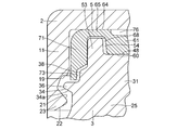
- FIG. 1 is a cross-sectional explanatory view taken along the line II of FIG. 2 showing a preferred example of an embodiment of the present invention.
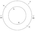
- FIG. 2 is an explanatory plan view of the example shown in FIG.
- FIG. 3 is an explanatory plan view of the upper case of the example shown in FIG. 4 is a cross-sectional explanatory view taken along the line IV-IV of the upper case shown in FIG.
- FIG. 5 is a partially enlarged cross-sectional explanatory view of the upper case shown in FIG. 6 is an explanatory plan view of the lower case of the example shown in FIG.
- FIG. 7 is a cross-sectional explanatory view taken along the line VII-VII of the lower case shown in FIG. FIG.
- FIG. 8 is a perspective explanatory view of the lower case shown in FIG.
- FIG. 9 is a partially enlarged cross-sectional explanatory view of the lower case shown in FIG.
- FIG. 10 is a partially enlarged cross-sectional explanatory view of the lower case shown in FIG.
- FIG. 11 is an enlarged plan view of the engaging protrusion of the lower case shown in FIG.
- FIG. 12 is an explanatory plan view of the slide bearing piece of the example shown in FIG. 13 is a cross-sectional explanatory view taken along the line XIII-XIII of the plain bearing piece shown in FIG.
- FIG. 16 is a partially enlarged cross-sectional explanatory view of the plain bearing piece shown in FIG.
- FIG. 17 is a partially enlarged plan explanatory view of the slide bearing piece shown in FIG. 18 is a partially enlarged plan explanatory view of the slide bearing piece shown in FIG.
- FIG. 19 is an explanatory plan view of another embodiment of the sliding bearing piece of the example shown in FIG. 20 is a cross-sectional explanatory view taken along the line XX-XX of the plain bearing piece shown in FIG.
- FIG. 21 is a partially enlarged cross-sectional explanatory view of a meshing portion between a lower case and a sliding bearing piece of the sliding bearing of the example shown in FIG. FIG.
- FIG. 22 is an explanatory plan view of a reinforcing member of the slide bearing of the example shown in FIG. 23 is a cross-sectional explanatory view taken along the line XXIII-XXIII of the reinforcing member shown in FIG. 24 is a partially enlarged cross-sectional explanatory view of a mounting portion between the lower case and the reinforcing member of the slide bearing of the example shown in FIG.
- FIG. 25 is a cross-sectional explanatory view in which the slide bearing of the example shown in FIG. 1 is incorporated in a strut suspension.
- a synthetic resin sliding bearing 1 of this example for use in a strut suspension in a four-wheeled vehicle includes a synthetic resin upper case 2 fixed to a vehicle body via an attachment member, A synthetic resin lower case 3 superimposed on the upper case 2 so as to be rotatable in the circumferential direction R around the axis O with respect to the upper case 2, and a space between the upper case 2 and the lower case 3 4 and a sliding bearing piece 5 made of synthetic resin.
- the upper case 2 particularly includes an annular upper case base 7 having an annular lower surface 6 in the vertical direction (axial direction) Y, and the radial direction X of the upper case base 7.
- a cylindrical outer periphery that is suspended from an inner circumferential cylindrical hanging portion 9 that hangs from the inner circumferential end 8 and a circular upper surface 12 that is suspended from the outer circumferential end portion 10 in the radial direction X of the upper case base 7
- An outer circumferential cylindrical hanging portion 11 having a surface 11a, and an upper circumferential cylindrical hanging portion that protrudes upward from the annular upper surface 12 of the upper case base portion 7 leaving an annular flat surface portion 13 on the outer circumferential side of the annular upper surface 12
- an annular pedestal portion 15 having an upper surface 15 a connected to the inner peripheral surface 14 of the cylinder 9.
- the end portion 16 of the outer circumferential side cylindrical hanging portion 11 extends further downward than the end portion 17 of the inner circumferential side cylindrical hanging portion 9, and the end portion 16 has an annular shoulder extending outward in the radial direction X.
- Part 19 annular shoulder 19, inclined surface part 20 that gradually expands outward in radial direction X, inclined surface part 21 and inclined surface part 21 that are connected to inclined surface part 20 and gradually contract inward in radial direction X.
- an engagement bulging portion 23 that has an inclined surface portion 22 that gradually expands outward in the radial direction X and bulges inward in the radial direction.
- the lower case 3 includes an annular lower case base 25 having an annular upper surface 24 in the vertical direction Y and an annular lower surface 26 of the lower case base 25 to the lower case base 25 as shown in FIGS.
- a cylindrical protruding portion 29 protruding downward with a cylindrical inner peripheral surface 28 connected to the cylindrical inner peripheral surface 27, and the cylindrical inner peripheral surface 27 and the annular shoulder portion 30 of the lower case base 25 from the annular upper surface 24 of the lower case base 25.
- An annular projecting portion 31 projecting upward leaving the outer circumferential surface 32 and a radial direction X formed on the lower surface 34 and extending outward in the radial direction X from the lower end 33 in the vertical direction Y of the cylindrical outer peripheral surface 32 of the annular projecting portion 31.
- annular flange portion 36 connected to the cylindrical outer peripheral surface 35 of the lower case base 25 via an inclined surface portion 34a that gradually decreases inward, and a cylindrical outer peripheral surface 32 of the lower end 33 of the annular protruding portion 31 in the radial direction X Poke outward
- at least one connected to the annular upper surface 37 of the annular flange 36, in FIG. 6, on the cylindrical outer peripheral surface 32 of the lower end 33 of the annular protrusion 31, six plan views are equally spaced along the circumferential direction R.
- the triangular protrusion 38 and the annular plate-shaped portion 40 extending outward in the radial direction X are integrally provided at the lower end 39 of the cylindrical outer peripheral surface 35 of the lower case base 25.
- An annular projecting portion 42 extending inward in the radial direction X is formed on the cylindrical inner peripheral surface 28 of the end portion 41 of the cylindrical projecting portion 29, and the annular end surface 43 of the cylindrical projecting portion 29 is open to the annular end surface 43.
- the outer peripheral surface 45 of the end 41 of the cylindrical projection 29 where the annular concave groove 44 is formed is lower in the vertical direction Y than the cylindrical outer peripheral surface 46 of the cylindrical projection 29.
- the end 41 of the cylindrical protruding portion 29 formed with the annular tapered surface 47 is provided with flexibility in the radial direction X. Has been.
- An annular upper surface 48 of the annular projecting portion 31 has an inner annular standing wall portion 51 projecting upward in the vertical direction Y with an inner peripheral surface 50 connected to the inner peripheral surface 49 of the annular projecting portion 31, and the annular projecting portion.
- An outer annular standing wall portion 53 that protrudes upward in the vertical direction Y is formed with a cylindrical outer circumferential surface 52 that is connected to the cylindrical outer circumferential surface 32, and the inner annular standing wall portion 51 and the annular upper surface 48 are formed on the annular upper surface 48.
- the annular recessed part 54 which consists of the outer side annular standing wall part 53 is formed.
- the annular upper surface 48 that is the bottom surface of the annular recess 54 has a hole portion 56 that has a bottom 55 that opens to the annular upper surface 48 and extends from the annular upper surface 48 to the lower case base 25 downward in the vertical direction Y.
- a plurality of lines are formed along the circumferential direction R.
- the hole 56 has an opening 57 that is rectangular in plan view, and gradually decreases as the long side 57 a side of the opening 57 extends downward in the vertical direction Y. It has an inclined surface 58 facing each other.
- the hole 56 makes the thickness of the lower case base 25 and the annular protrusion 31 as uniform as possible to prevent the occurrence of sink marks or the like during molding as much as possible.
- the synthetic resin sliding bearing piece 5 disposed in the space 4 has an annular shape in the vertical direction Y that slidably contacts the annular lower surface 6 of the upper case base 7 as shown in FIGS. And an annular upper surface 48 which is a bottom surface of the annular recess 54 and is fitted into an annular recess 54 formed on the annular upper surface 48 of the annular protrusion 31 of the lower case base 25.
- An annular thrust sliding bearing piece 61 having a lower surface 60, and a thin wall extending outward in the radial direction X with an annular upper surface 64 connected to an annular upper surface 59 at the upper end 63 of the cylindrical outer peripheral surface 62 of the thrust sliding bearing piece 61.
- An annular recess 68 is formed in cooperation with the cylindrical outer circumferential surface 62 of the thrust slide bearing piece 61 and the annular lower surface 67 of the annular coupling piece 65 at the outer circumferential end 66 of the annular coupling piece 65. And then droop A cylindrical radial sliding bearing piece 71 having a cylindrical inner peripheral surface 69 and a cylindrical outer peripheral surface 70 on the lower side of the cylindrical inner peripheral surface 69 of the radial sliding bearing piece 71 and a triangular convex portion 72 and a plane.
- the protrusion 38 formed at the lower end 33 of the annular protrusion 31 of the lower case 3 is engaged with the concave portion 73 of the concave / convex engagement portion 74, so that the slide bearing piece 5 rotates around the axis O with respect to the lower case 3.
- the concave-convex engagement portion 74 is formed in the circumferential direction R of the cylindrical inner peripheral surface 69 of the radial sliding bearing piece 71.
- the concave-convex engagement portion 74 may be formed only on the cylindrical inner peripheral surface 69 of the radial sliding bearing piece portion 71 corresponding to the projection portion 38.
- the thrust slide bearing piece 61 has a plurality of inner recesses 75 and outer recesses 76 formed in an annular upper surface 59 along the circumferential direction R and in the radial direction X over at least two rows of the inner row and the outer row. is doing.
- Each of the plurality of inner recesses 75 formed in the inner row has an inner arc-shaped wall surface 77 extending in an arc shape with the axis O as the center, and an axially outward axis in the radial direction X with respect to the inner arc-shaped wall surface 77.
- An outer arc-shaped wall surface 78 extending in an arc shape around the center O, that is, expanded in the radial direction X with respect to the inner arc-shaped wall surface 77, and the inner arc-shaped wall surface 77 and the outer arc-shaped wall surface 78, respectively.
- a pair of semicircular wall surfaces 79 connected to each other in the circumferential direction R and a bottom wall surface 75a connected to each of the inner arcuate wall surface 77, the outer arcuate wall surface 78, and the pair of semicircular wall surfaces 79. It is prescribed by.
- Each of the plurality of outer recesses 76 arranged in the outer row has an inner arcuate wall surface 80 extending in an arc shape with the axis O as a center, and an axis extending outward in the radial direction X with respect to the inner arcuate wall surface 80.
- the outer arc-shaped wall surface 81 extending in the arc shape around the center O, that is, expanded in the radial direction X with respect to the inner arc-shaped wall surface 80, and the inner arc-shaped wall surface 80 and the outer arc-shaped wall surface 81, respectively.
- a plurality of inner recesses 75 and outer recesses 76 formed on the annular upper surface 59 of the thrust slide bearing piece 61 along the circumferential direction R and in two rows of the inner row and the outer row in the radial direction X include an inner recess portion.
- the total area of the opening surface 84 of the inner recess 75 and the outer recess 76 occupying the total area of the opening surface 84 of the outer recess 76 and the outer recess 76 and the annular upper surface 59 of the thrust slide bearing piece 61 which is a thrust slide bearing surface. Is preferably 20 to 50%, more preferably 30 to 40%.
- a radial sliding bearing piece 71 shown in FIGS. 12 to 18 is opened at both ends in the vertical direction Y, and is formed with a plurality of axial grooves 85 formed on the cylindrical outer peripheral surface 70 at regular intervals in the circumferential direction R. have.
- the plurality of axial grooves 85 formed in the cylindrical outer peripheral surface 70 of the bearing piece 71 serve as a reservoir for lubricating oil such as grease.
- the annular upper surface 59 is arranged along the circumferential direction R, and in the radial direction X, the inner ring extends over two rows of the inner row and the outer row.
- a concave groove 86 and an outer annular concave groove 87 are formed, and a plurality of axial grooves 85 are formed at equal intervals in the circumferential direction R on the cylindrical outer peripheral surface 70 of the radial plain bearing piece 71. May be.
- An inner annular groove 86 and an outer annular groove 87 formed on the annular upper surface 59 of the thrust sliding bearing piece 61 along the circumferential direction R and in the radial direction X over two rows of the inner row and the outer row are:
- the inner annular concave groove 86 and the inner annular concave groove 86 occupying the total area of the opening surface 88 of the inner annular concave groove 86 and the outer annular concave groove 87 and the annular upper surface 59 of the thrust sliding bearing piece 61 which is a thrust sliding bearing surface.
- the ratio of the total area of the opening surface 88 of the outer annular groove 87 is preferably 20 to 50%, more preferably 30 to 40%.
- the inner concave portion 75 and the outer concave portion 76, or the inner annular concave groove 86 and the outer annular concave groove 87 are formed on the annular upper surface 59.
- the thrust slide bearing surface is formed in the relative rotation in the circumferential direction R about the axis O between the annular upper surface 59 of the thrust slide bearing piece 61 and the annular lower surface 6 of the upper case base 7.
- the contact area between the annular upper surface 59 serving as a sliding surface and the mating member, that is, the annular lower surface 6 of the upper case base 7 is reduced to reduce the contact pressure acting on the annular upper surface 59 (per unit area).
- the friction of the lubricating oil filled in the inner concave portion 75 and the outer concave portion 76 or the inner annular concave groove 86 and the outer annular concave groove 87 can be reduced. Low due to surface intervention It is possible to achieve a further reduction in friction me and Kosuka is coupled with.
- the sliding bearing piece 5 has a thrust sliding bearing piece 61 fitted in an annular recess 54 formed on the annular upper surface 48 of the annular projection 31 of the lower case base 25.
- the annular lower surface 60 is brought into contact with the annular upper surface 48 which is the bottom surface of the annular recess 54, the annular recess 68 is fitted into the outer annular standing wall 53 of the annular recess 54, and the cylindrical inner periphery of the radial sliding bearing piece portion 71 is inserted.
- the lower case 3 By engaging the protrusions 38 formed on the lower end 33 of the cylindrical outer peripheral surface 32 of the annular protrusion 31 of the lower case base 25 with the recesses 73 of the concave and convex engagement portion 74 formed on the surface 69, the lower case 3 is engaged. Thus, rotation in the circumferential direction R around the axis O is prohibited, and the lower case 3 is integrated and assembled to the lower case 3.
- the upper case 2 has an annular lower surface 6 on the annular upper surface 59 of the thrust sliding bearing piece 61 of the sliding bearing piece 5 and a cylindrical inner circumferential surface 18 of the outer cylindrical hanging portion 11 on the radial sliding bearing piece 71.
- the inclined surface portion 21 of the engagement bulging portion 23 formed on the end portion 16 of the cylindrical inner peripheral surface 18 of the outer peripheral side cylindrical hanging portion 11 is slidably brought into contact with the cylindrical inner peripheral surface 69.
- the lower case 3 is assembled by being elastically attached to an annular flange 36 connected to the cylindrical outer peripheral surface 35 of the base 25.
- the slide bearing piece 5 Since the slide bearing piece 5 is integrated with the lower case 3 by prohibiting rotation in the circumferential direction R around the axis O with respect to the lower case 3, the slide bearing piece 5, the upper case 2, and the lower case are integrated. 3, sliding between the sliding bearing piece 5 and the lower case 3 is prohibited, and between the annular upper surface 59 of the thrust sliding bearing piece 61 and the annular lower surface 6 of the upper case base 7 and the radial sliding bearing piece. Smooth sliding is possible because it is limited to the sliding of synthetic resin excellent in sliding characteristics between the cylindrical inner peripheral surface 69 of the portion 71 and the cylindrical inner peripheral surface 18 of the outer cylindrical hanging portion 11 of the upper case base 7. The operation is performed.
- a metal reinforcing member 91 having a cylindrical portion 89 and a wide annular flange 90 extending outward in the radial direction X at one end of the cylindrical portion 89 is provided. 1 and 24, the surface 92 of the annular flange 90 is brought into contact with the annular lower surface 26 of the lower case base 25, and the cylindrical inner peripheral surface 93 of the cylindrical portion 89 is protruded from the cylinder of the lower case base 25.
- the lower case 3 is disposed so as to be fitted into the cylindrical outer peripheral surface 46 of the portion 29.
- the annular lower surface 26 of the lower case base 25 of the lower case 3 serving as a spring seat for the suspension coil spring is formed on the annular flange 90 of the reinforcing member 91. Reinforced by.
- the end 41 of the cylindrical protruding portion 29 on which the annular tapered surface 47 of the lower case base 25 is formed is elastically deformed by flexibility and the cylindrical protruding portion of the reinforcing member 91. 29 is easily inserted into the cylindrical outer peripheral surface 46, and after the insertion, as shown in FIG. 24, the annular tapered surface 47 of the end portion 41 of the cylindrical protruding portion 29 is the cylinder of the cylindrical protruding portion 29.
- the sliding bearing 1 formed in this way makes the annular pedestal portion 15 of the upper surface 15 a of the upper case 2 abut against the mounting member 94 on the vehicle body side, and the suspension coil spring 95.
- An annular lower surface 26 of the lower case base 25 serving as a spring seat surface or an annular flange 90 of a metal reinforcing member 91 attached to the annular lower surface 26 of the lower case base 25 is brought into contact with the upper end of
- the synthetic resin sliding bearing 1 of this example is arranged between the vehicle body side seating surface 96 of the mounting member 94 on the vehicle body side and the upper end of the suspension coil spring 95, and the synthetic resin sliding bearing 1 of this example. May be applied to a strut suspension of a four-wheeled vehicle.
- the relative rotation in the circumferential direction R of the suspension coil spring 95 with respect to the mounting member 94 on the vehicle body side causes the thrust sliding bearing piece portion with respect to the annular lower surface 6 of the upper case base 7 in the sliding bearing 1.
Landscapes
- Engineering & Computer Science (AREA)
- General Engineering & Computer Science (AREA)
- Mechanical Engineering (AREA)
- Sliding-Contact Bearings (AREA)
- Vehicle Body Suspensions (AREA)
- Fluid-Damping Devices (AREA)
Abstract
Description
2 上部ケース
3 下部ケース
4 空間
5 滑り軸受片
6 円環状下面
7 上部ケース基部
9 内周側円筒垂下部
11 外周側円筒垂下部
23 係合膨出部
25 下部ケース基部
29 円筒突出部
31 円環状突出部
36 円環状鍔部
38 突起部
48 円環状上面
51 内側環状立壁部
53 外側環状立壁部
54 円環状凹部
61 スラスト滑り軸受片部
71 ラジアル滑り軸受片部
72 凸部
73 凹部
74 凹凸噛合部
91 補強部材 DESCRIPTION OF
7
Claims (11)
- 合成樹脂製の上部ケースと、この上部ケースに対して軸心の回りで円周方向に回転自在となるように、当該上部ケースに重ね合わされている強化合成樹脂製の下部ケースと、上部ケース及び下部ケース間に配されている合成樹脂製の滑り軸受片とを具備しており、上部ケースは、上下方向において円環状下面を有した上部ケース基部と、この上部ケース基部の径方向の内周端部から垂下した内周側円筒垂下部と、上部ケース基部の径方向の外周端部から垂下した外周側円筒垂下部と、この外周側円筒垂下部の円筒内周面の下部に設けられた係合膨出部とを具備しており、下部ケースは、上下方向において円環状上面を有した下部ケース基部と、この下部ケース基部の円筒内周面に連接する円筒内周面をもって下部ケース基部の円環状下面から下方に突出する円筒突出部と、下部ケース基部の円環状上面から上方に突出した円環状突出部と、この円環状突出部の円環状上面に該円環状上面と協同して環状凹部を形成するように、当該円環状突出部の円環状上面から上方に突出した内周側環状立壁部及び外周側環状立壁部と、円環状突出部の円筒外周面の下端部から径方向の外方に突出した円環状鍔部と、上下方向に関しての円環状突出部の円環状上面及び円環状鍔部間において円環状突出部の円筒外周面から径方向の外方に突出した少なくとも一つの突起部と、下部ケース基部の円筒外周面の下端部から径方向の外方に突出した円環状板状部とを具備しており、滑り軸受片は、上下方向における円環状の上面及び円環状の下面を有する円環状のスラスト滑り軸受片部と、このスラスト滑り軸受片部の外周端部から円環状の上面と連接する環状上面をもって径方向の外方に伸びる環状連結片部と、この環状連結片部の外周端部から垂下すると共に円筒内周面及び円筒外周面を有した円筒状のラジアル滑り軸受片部と、このラジアル滑り軸受片部の円筒内周面に円周方向に沿って交互に形成された凸部及び凹部を有した凹凸噛合部とを備えており、滑り軸受片は、スラスト滑り軸受片部を下部ケースの環状凹部に嵌挿させ、ラジアル滑り軸受片部の円筒内周面を外周側環状立壁部及び円環状突出部の円筒外周面に接触させると共に下部ケースに対しての軸心の回りでの円周方向の回転が禁止されるように、凹凸噛合部の凹部を突起部に噛合させて、上部ケース及び下部ケース間に配されており、上部ケースは、上部ケース基部の円環状下面をスラスト滑り軸受片部の円環状の上面に摺動自在に接触させると共に外周側円筒垂下部の円筒内周面をラジアル滑り軸受片部の円筒外周面に摺動自在に接触させ、係合膨出部を下部ケースの円環状鍔部に弾性装着させて下部ケースに組合されている合成樹脂製の滑り軸受。 An upper case made of a synthetic resin, a lower case made of a reinforced synthetic resin superimposed on the upper case so as to be rotatable in a circumferential direction around the axis with respect to the upper case, an upper case, and The upper case includes an upper case base having an annular lower surface in the vertical direction, and a radially inner periphery of the upper case base. Provided in the lower part of the cylindrical inner peripheral surface of the outer peripheral side cylindrical hanging part, the outer peripheral side cylindrical hanging part hanging from the inner peripheral side cylindrical hanging part hanging from the end part, the outer peripheral side cylindrical hanging part suspended from the radial outer peripheral end part of the upper case base The lower case has a lower case base having an annular upper surface in the vertical direction and a cylindrical inner peripheral surface connected to the cylindrical inner peripheral surface of the lower case base. The annular underside of A cylindrical projecting portion projecting downward, an annular projecting portion projecting upward from the annular upper surface of the lower case base, and an annular recess formed on the annular upper surface of the annular projecting portion in cooperation with the annular upper surface As described above, the inner peripheral side annular standing wall portion and the outer peripheral side annular standing wall portion projecting upward from the annular top surface of the annular projecting portion, and the lower end portion of the cylindrical outer peripheral surface of the annular projecting portion project radially outward. And at least one protrusion protruding outward in the radial direction from the cylindrical outer peripheral surface of the annular protrusion between the annular upper surface and the annular flange between the annular protrusion and the annular protrusion in the vertical direction, An annular plate-like portion protruding radially outward from the lower end of the cylindrical outer peripheral surface of the lower case base, and the sliding bearing piece has an annular upper surface and an annular lower surface in the vertical direction. An annular thrust plain bearing piece and this thrust An annular connecting piece portion extending radially outward from an outer peripheral end portion of the slide bearing piece portion and having an annular upper surface connected to the annular upper surface, and a cylindrical inner peripheral surface hanging from the outer peripheral end portion of the annular connecting piece portion, and A cylindrical radial sliding bearing piece portion having a cylindrical outer peripheral surface, and a concave-convex meshing portion having convex portions and concave portions alternately formed along the circumferential direction on the cylindrical inner peripheral surface of the radial sliding bearing piece portion; The sliding bearing piece has a thrust sliding bearing piece portion fitted into the annular recess of the lower case, and the cylindrical inner peripheral surface of the radial sliding bearing piece portion is arranged on the outer peripheral annular standing wall portion and the annular outer periphery of the annular protruding portion. The concave-convex engagement portion is engaged with the protrusion so that contact with the surface and circumferential rotation around the axis with respect to the lower case are prohibited, and the projection is disposed between the upper case and the lower case. The upper case is the upper case base The annular lower surface is slidably brought into contact with the annular upper surface of the thrust slide bearing piece, and the cylindrical inner circumferential surface of the outer cylindrical hanging portion is slidably brought into contact with the cylindrical outer face of the radial slide bearing piece, A sliding bearing made of synthetic resin in which an engagement bulging portion is elastically attached to an annular flange portion of a lower case and combined with the lower case.
- 下部ケース基部及びこの下部ケース基部の円環状下面から下方に突出する円筒突出部は、当該円筒突出部の円筒外周面に嵌挿された円筒部と該円筒部の一方の端部に一体的に形成されていると共に下部ケース基部の円環状下面に接触した環状鍔部とを有した金属製の補強部材によって補強されている請求項1に記載の合成樹脂製の滑り軸受。 The lower case base and the cylindrical protruding portion that protrudes downward from the annular lower surface of the lower case base are integrally formed with the cylindrical portion inserted into the cylindrical outer peripheral surface of the cylindrical protruding portion and one end portion of the cylindrical portion. The synthetic resin sliding bearing according to claim 1, wherein the sliding bearing is made of a synthetic resin and is reinforced by a metal reinforcing member having an annular flange portion that is formed and is in contact with the annular lower surface of the lower case base.
- 円筒突出部の環状端面には、環状凹溝が形成されており、この環状凹溝が形成された円筒突出部の円筒外周面の端部外周面は、当該端部外周面を除く円筒突出部の円筒外周面よりも径方向の外方に円筒突出部の環状端面に向かうに連れて漸次拡がる環状テーパ面として形成されており、円筒突出部の円筒外周面に嵌挿された補強部材は、円筒部において円筒突出部の環状テーパ面として形成された端部外周面が該円筒部の下端面側で径方向の外方に突出することにより、下方向に抜け止めされている請求項1又は2に記載の合成樹脂製の滑り軸受。 An annular groove is formed on the annular end surface of the cylindrical protrusion, and the outer peripheral surface of the cylindrical outer surface of the cylindrical protrusion formed with the annular groove is a cylindrical protrusion excluding the outer peripheral surface of the end. Is formed as an annular tapered surface that gradually expands toward the annular end surface of the cylindrical protruding portion outward in the radial direction from the outer peripheral surface of the cylinder, and the reinforcing member inserted into the cylindrical outer peripheral surface of the cylindrical protruding portion is The end portion outer peripheral surface formed as an annular tapered surface of the cylindrical protruding portion in the cylindrical portion protrudes radially outward on the lower end surface side of the cylindrical portion, and is prevented from falling downward. 2. A synthetic resin sliding bearing according to 2.
- スラスト滑り軸受片部は、その円環状の上面に円周方向に沿うと共に径方向に少なくとも内側列と外側列の二列にわたって形成された複数個の内側凹部及び外側凹部を有しており、この内側凹部と外側凹部とは、互に円周方向に位相差をもって配列されており、ラジアル軸受片部は、上下方向において開口していると共にその円筒外周面に円周方向に等間隔に離間して形成された複数個の軸方向溝を有している請求項1から3のいずれか一項に記載の合成樹脂製の滑り軸受。 The thrust slide bearing piece has a plurality of inner and outer recesses formed along the circumferential direction on the annular upper surface and at least two rows of the inner row and the outer row in the radial direction. The inner concave portion and the outer concave portion are arranged with a phase difference in the circumferential direction, and the radial bearing piece portions are opened in the vertical direction and spaced apart from the cylindrical outer circumferential surface at equal intervals in the circumferential direction. The synthetic resin sliding bearing according to any one of claims 1 to 3, further comprising a plurality of axial grooves formed as described above.
- 複数個の内側凹部の夫々は、軸心を中心として円弧状に伸びた内側円弧状壁面と、この内側円弧状壁面に対して径方向外方で軸心を中心として円弧状に伸びた外側円弧状壁面と、これら内側円弧状壁面及び外側円弧状壁面の夫々に連接されていると共に互いに円周方向において対面する一対の半円状壁面と、これら内側円弧状壁面、外側円弧状壁面及び一対の半円状壁面の夫々に連接された底壁面とによって規定されている請求項4に記載の合成樹脂製の滑り軸受。 Each of the plurality of inner recesses includes an inner arc-shaped wall surface extending in an arc shape centering on the axis, and an outer circle extending in an arc shape centering on the axis center radially outward with respect to the inner arc-shaped wall surface. An arc-shaped wall surface, a pair of semicircular wall surfaces connected to each of the inner arc-shaped wall surface and the outer arc-shaped wall surface and facing each other in the circumferential direction, the inner arc-shaped wall surface, the outer arc-shaped wall surface and the pair of The sliding bearing made of synthetic resin according to claim 4, defined by a bottom wall surface connected to each of the semicircular wall surfaces.
- 複数個の外側凹部の夫々は、軸心を中心として円弧状に伸びた内側円弧状壁面と、この内側円弧状壁面に対して径方向外方で軸心を中心として円弧状に伸びた外側円弧状壁面と、これら内側円弧状壁面及び外側円弧状壁面の夫々に連接されていると共に互いに円周方向において対面する一対の半円状壁面と、これら内側円弧状壁面、外側円弧状壁面及び一対の半円状壁面の夫々に連接された底壁面とによって規定されている請求項4又は5に記載の合成樹脂製の滑り軸受。 Each of the plurality of outer concave portions includes an inner arc-shaped wall surface extending in an arc shape centering on the axis, and an outer circle extending in an arc shape centering on the axis center radially outward with respect to the inner arc-shaped wall surface. An arc-shaped wall surface, a pair of semicircular wall surfaces connected to each of the inner arc-shaped wall surface and the outer arc-shaped wall surface and facing each other in the circumferential direction, the inner arc-shaped wall surface, the outer arc-shaped wall surface and the pair of The synthetic resin sliding bearing according to claim 4 or 5, defined by a bottom wall surface connected to each of the semicircular wall surfaces.
- 複数個の内側凹部及び外側凹部の開口面とスラスト滑り軸受片部の円環状の上面とを合わせた面に占める複数個の内側凹部及び外側凹部の開口面の総面積の割合は、20~50%である請求項4から6のいずれか一項に記載の合成樹脂製の滑り軸受。 The ratio of the total area of the opening surfaces of the plurality of inner recesses and outer recesses to the total surface of the opening surfaces of the plurality of inner recesses and outer recesses and the annular upper surface of the thrust slide bearing piece is 20-50. The synthetic resin sliding bearing according to any one of claims 4 to 6, wherein the sliding bearing is made of synthetic resin.
- スラスト滑り軸受片は、その円環状の上面に円周方向に沿うと共に互いに同心に形成された少なくとも内側列と外側列の二列にわたって形成された円環状凹溝を有している請求項1から3のいずれか一項に記載の合成樹脂製の滑り軸受。 The thrust sliding bearing piece has annular concave grooves formed in at least two inner rows and outer rows formed along the circumferential direction and concentrically with each other on the upper surface of the annular slide bearing. 4. A synthetic resin sliding bearing according to any one of 3 above.
- 円環状凹溝の開口面とスラスト滑り軸受片部の円環状の上面とを合わせた面に占める少なくとも2個の円環状凹溝の開口面の総面積の割合は、20~50%である請求項8に記載の合成樹脂製の滑り軸受。 The ratio of the total area of the opening surfaces of at least two annular grooves to the combined surface of the opening surface of the annular groove and the annular upper surface of the thrust sliding bearing piece is 20 to 50%. Item 9. A synthetic resin sliding bearing according to Item 8.
- スラスト滑り軸受片は、その円環状の上面に円周方向に沿うと共に互いに同心に形成された少なくとも内側列と外側列の二列にわたって形成された円環状凹溝を有している請求項4から7のいずれか一項に記載の合成樹脂製の滑り軸受。 5. The thrust slide bearing piece has annular concave grooves formed on at least two inner rows and outer rows that are formed along the circumferential direction and concentrically with each other on the upper surface of the annular slide bearing. A sliding bearing made of synthetic resin according to any one of claims 7 to 9.
- 複数個の内側凹部及び外側凹部の開口面と円環状凹溝の開口面とスラスト滑り軸受片部の円環状の上面とを合わせた面に占める複数個の内側凹部及び外側凹部の開口面並びに少なくとも2個の円環状凹溝の開口面の総面積の割合は、20~50%である請求項10に記載の合成樹脂製の滑り軸受。 A plurality of inner recesses and outer recess opening surfaces that occupy a combined surface of the opening surfaces of the plurality of inner recesses and outer recesses, the opening surface of the annular groove and the annular upper surface of the thrust slide bearing piece, and at least The synthetic resin sliding bearing according to claim 10, wherein the ratio of the total area of the opening surfaces of the two annular grooves is 20 to 50%.
Priority Applications (6)
| Application Number | Priority Date | Filing Date | Title |
|---|---|---|---|
| EP14751917.7A EP2957785B1 (en) | 2013-02-15 | 2014-02-05 | Synthetic resin plain bearing |
| CN201480008890.9A CN104995420B (en) | 2013-02-15 | 2014-02-05 | synthetic resin sliding bearing |
| ES14751917.7T ES2649727T3 (en) | 2013-02-15 | 2014-02-05 | Plain synthetic resin bearing |
| KR1020157021757A KR101700923B1 (en) | 2013-02-15 | 2014-02-05 | Synthetic resin-made sliding bearing |
| BR112015018746-3A BR112015018746B1 (en) | 2013-02-15 | 2014-02-05 | SYNTHETIC RESIN SLIDING BEARING |
| US14/767,397 US9556906B2 (en) | 2013-02-15 | 2014-02-05 | Synthetic resin-made sliding bearing |
Applications Claiming Priority (2)
| Application Number | Priority Date | Filing Date | Title |
|---|---|---|---|
| JP2013028462A JP6017340B2 (en) | 2013-02-15 | 2013-02-15 | Synthetic plastic plain bearing |
| JP2013-028462 | 2013-02-15 |
Publications (1)
| Publication Number | Publication Date |
|---|---|
| WO2014125792A1 true WO2014125792A1 (en) | 2014-08-21 |
Family
ID=51353805
Family Applications (1)
| Application Number | Title | Priority Date | Filing Date |
|---|---|---|---|
| PCT/JP2014/000603 WO2014125792A1 (en) | 2013-02-15 | 2014-02-05 | Synthetic resin plain bearing |
Country Status (8)
| Country | Link |
|---|---|
| US (1) | US9556906B2 (en) |
| EP (1) | EP2957785B1 (en) |
| JP (1) | JP6017340B2 (en) |
| KR (1) | KR101700923B1 (en) |
| CN (1) | CN104995420B (en) |
| BR (1) | BR112015018746B1 (en) |
| ES (1) | ES2649727T3 (en) |
| WO (1) | WO2014125792A1 (en) |
Cited By (2)
| Publication number | Priority date | Publication date | Assignee | Title |
|---|---|---|---|---|
| WO2019172004A1 (en) * | 2018-03-06 | 2019-09-12 | オイレス工業株式会社 | Spring seat, and suspension mounting structure |
| US10422374B2 (en) | 2015-11-20 | 2019-09-24 | Oiles Corporation | Synthetic resin-made sliding bearing |
Families Citing this family (6)
| Publication number | Priority date | Publication date | Assignee | Title |
|---|---|---|---|---|
| JP6466708B2 (en) * | 2014-12-12 | 2019-02-06 | オイレス工業株式会社 | Thrust bearing for vehicles |
| JP6602042B2 (en) * | 2015-04-28 | 2019-11-06 | オイレス工業株式会社 | Plain bearing |
| WO2018074254A1 (en) * | 2016-10-18 | 2018-04-26 | オイレス工業株式会社 | Sliding bearing |
| JP6946138B2 (en) * | 2017-10-03 | 2021-10-06 | オイレス工業株式会社 | Thrust plain bearing |
| JP7128002B2 (en) * | 2018-03-22 | 2022-08-30 | オイレス工業株式会社 | Sliding bearing and manufacturing method thereof |
| KR102285574B1 (en) * | 2020-07-30 | 2021-08-05 | 에스티엠(주) | Strut bearing assembly |
Citations (5)
| Publication number | Priority date | Publication date | Assignee | Title |
|---|---|---|---|---|
| JP2004293589A (en) | 2003-03-25 | 2004-10-21 | Oiles Ind Co Ltd | Strut sliding bearing |
| JP2009250278A (en) | 2008-04-02 | 2009-10-29 | Oiles Ind Co Ltd | Thrust sliding bearing |
| JP2009257516A (en) * | 2008-04-18 | 2009-11-05 | Oiles Ind Co Ltd | Thrust slide bearing |
| WO2012114679A1 (en) * | 2011-02-23 | 2012-08-30 | オイレス工業株式会社 | Synthetic resin thrust sliding bearing |
| JP2013002603A (en) * | 2011-06-20 | 2013-01-07 | Oiles Corp | Thrust sliding bearing |
Family Cites Families (8)
| Publication number | Priority date | Publication date | Assignee | Title |
|---|---|---|---|---|
| JP2538944B2 (en) | 1987-10-14 | 1996-10-02 | 富士通株式会社 | Dry etching equipment |
| JP4482961B2 (en) | 1999-07-15 | 2010-06-16 | オイレス工業株式会社 | Synthetic plastic plain bearing |
| JP3988397B2 (en) | 2001-02-27 | 2007-10-10 | オイレス工業株式会社 | Synthetic plastic plain bearing |
| JP5157210B2 (en) * | 2007-03-20 | 2013-03-06 | オイレス工業株式会社 | Thrust slide bearing and combination mechanism of this thrust slide bearing with piston rod and coil spring |
| DE102008057590A1 (en) | 2008-08-13 | 2010-02-18 | Schaeffler Kg | Strut bearings |
| JP5516210B2 (en) | 2010-08-06 | 2014-06-11 | オイレス工業株式会社 | Thrust sliding bearing |
| JP5673110B2 (en) * | 2011-01-07 | 2015-02-18 | オイレス工業株式会社 | Thrust slide bearing and strut suspension mounting structure using this thrust slide bearing |
| JP5906590B2 (en) | 2011-06-09 | 2016-04-20 | オイレス工業株式会社 | Synthetic plastic plain bearing |
-
2013
- 2013-02-15 JP JP2013028462A patent/JP6017340B2/en active Active
-
2014
- 2014-02-05 WO PCT/JP2014/000603 patent/WO2014125792A1/en active Application Filing
- 2014-02-05 BR BR112015018746-3A patent/BR112015018746B1/en active IP Right Grant
- 2014-02-05 KR KR1020157021757A patent/KR101700923B1/en active IP Right Grant
- 2014-02-05 CN CN201480008890.9A patent/CN104995420B/en active Active
- 2014-02-05 US US14/767,397 patent/US9556906B2/en active Active
- 2014-02-05 ES ES14751917.7T patent/ES2649727T3/en active Active
- 2014-02-05 EP EP14751917.7A patent/EP2957785B1/en active Active
Patent Citations (5)
| Publication number | Priority date | Publication date | Assignee | Title |
|---|---|---|---|---|
| JP2004293589A (en) | 2003-03-25 | 2004-10-21 | Oiles Ind Co Ltd | Strut sliding bearing |
| JP2009250278A (en) | 2008-04-02 | 2009-10-29 | Oiles Ind Co Ltd | Thrust sliding bearing |
| JP2009257516A (en) * | 2008-04-18 | 2009-11-05 | Oiles Ind Co Ltd | Thrust slide bearing |
| WO2012114679A1 (en) * | 2011-02-23 | 2012-08-30 | オイレス工業株式会社 | Synthetic resin thrust sliding bearing |
| JP2013002603A (en) * | 2011-06-20 | 2013-01-07 | Oiles Corp | Thrust sliding bearing |
Non-Patent Citations (1)
| Title |
|---|
| See also references of EP2957785A4 |
Cited By (4)
| Publication number | Priority date | Publication date | Assignee | Title |
|---|---|---|---|---|
| US10422374B2 (en) | 2015-11-20 | 2019-09-24 | Oiles Corporation | Synthetic resin-made sliding bearing |
| WO2019172004A1 (en) * | 2018-03-06 | 2019-09-12 | オイレス工業株式会社 | Spring seat, and suspension mounting structure |
| JP2019152315A (en) * | 2018-03-06 | 2019-09-12 | オイレス工業株式会社 | Spring seat and suspension attachment structure |
| JP7002366B2 (en) | 2018-03-06 | 2022-01-20 | オイレス工業株式会社 | Suspension mounting structure |
Also Published As
| Publication number | Publication date |
|---|---|
| KR20150104207A (en) | 2015-09-14 |
| JP2014156908A (en) | 2014-08-28 |
| EP2957785A1 (en) | 2015-12-23 |
| BR112015018746B1 (en) | 2020-10-06 |
| US9556906B2 (en) | 2017-01-31 |
| US20150377286A1 (en) | 2015-12-31 |
| KR101700923B1 (en) | 2017-01-31 |
| EP2957785B1 (en) | 2017-10-11 |
| ES2649727T3 (en) | 2018-01-15 |
| CN104995420B (en) | 2017-07-04 |
| EP2957785A4 (en) | 2016-07-27 |
| BR112015018746A2 (en) | 2017-07-18 |
| JP6017340B2 (en) | 2016-10-26 |
| CN104995420A (en) | 2015-10-21 |
Similar Documents
| Publication | Publication Date | Title |
|---|---|---|
| JP6017340B2 (en) | Synthetic plastic plain bearing | |
| JP6194586B2 (en) | Synthetic plastic plain bearing | |
| JP6057814B2 (en) | Synthetic plastic plain bearing | |
| JP5332379B2 (en) | Synthetic plastic thrust plain bearing | |
| JP5910000B2 (en) | Synthetic plastic plain bearing | |
| US9707816B2 (en) | Synthetic resin-made sliding bearing | |
| WO2013108596A1 (en) | Thrust sliding bearing | |
| JP5842402B2 (en) | Thrust sliding bearing | |
| US9239081B2 (en) | Synthetic resin-made sliding bearing | |
| JP6631648B2 (en) | Slide bearing made of synthetic resin | |
| JP6211124B2 (en) | Synthetic plastic plain bearing |
Legal Events
| Date | Code | Title | Description |
|---|---|---|---|
| 121 | Ep: the epo has been informed by wipo that ep was designated in this application |
Ref document number: 14751917 Country of ref document: EP Kind code of ref document: A1 |
|
| REEP | Request for entry into the european phase |
Ref document number: 2014751917 Country of ref document: EP |
|
| WWE | Wipo information: entry into national phase |
Ref document number: 2014751917 Country of ref document: EP |
|
| ENP | Entry into the national phase |
Ref document number: 20157021757 Country of ref document: KR Kind code of ref document: A |
|
| WWE | Wipo information: entry into national phase |
Ref document number: 14767397 Country of ref document: US |
|
| NENP | Non-entry into the national phase |
Ref country code: DE |
|
| REG | Reference to national code |
Ref country code: BR Ref legal event code: B01A Ref document number: 112015018746 Country of ref document: BR |
|
| ENP | Entry into the national phase |
Ref document number: 112015018746 Country of ref document: BR Kind code of ref document: A2 Effective date: 20150805 |