WO2014122848A1 - マルチディスク変速機 - Google Patents
マルチディスク変速機 Download PDFInfo
- Publication number
- WO2014122848A1 WO2014122848A1 PCT/JP2013/082965 JP2013082965W WO2014122848A1 WO 2014122848 A1 WO2014122848 A1 WO 2014122848A1 JP 2013082965 W JP2013082965 W JP 2013082965W WO 2014122848 A1 WO2014122848 A1 WO 2014122848A1
- Authority
- WO
- WIPO (PCT)
- Prior art keywords
- disk
- shaft
- primary
- disc
- input shaft
- Prior art date
- Legal status (The legal status is an assumption and is not a legal conclusion. Google has not performed a legal analysis and makes no representation as to the accuracy of the status listed.)
- Ceased
Links
Images




Classifications
-
- F—MECHANICAL ENGINEERING; LIGHTING; HEATING; WEAPONS; BLASTING
- F16—ENGINEERING ELEMENTS AND UNITS; GENERAL MEASURES FOR PRODUCING AND MAINTAINING EFFECTIVE FUNCTIONING OF MACHINES OR INSTALLATIONS; THERMAL INSULATION IN GENERAL
- F16H—GEARING
- F16H37/00—Combinations of mechanical gearings, not provided for in groups F16H1/00 - F16H35/00
- F16H37/02—Combinations of mechanical gearings, not provided for in groups F16H1/00 - F16H35/00 comprising essentially only toothed or friction gearings
- F16H37/021—Combinations of mechanical gearings, not provided for in groups F16H1/00 - F16H35/00 comprising essentially only toothed or friction gearings toothed gearing combined with continuously variable friction gearing
-
- F—MECHANICAL ENGINEERING; LIGHTING; HEATING; WEAPONS; BLASTING
- F16—ENGINEERING ELEMENTS AND UNITS; GENERAL MEASURES FOR PRODUCING AND MAINTAINING EFFECTIVE FUNCTIONING OF MACHINES OR INSTALLATIONS; THERMAL INSULATION IN GENERAL
- F16H—GEARING
- F16H15/00—Gearings for conveying rotary motion with variable gear ratio, or for reversing rotary motion, by friction between rotary members
- F16H15/02—Gearings for conveying rotary motion with variable gear ratio, or for reversing rotary motion, by friction between rotary members without members having orbital motion
- F16H15/04—Gearings providing a continuous range of gear ratios
- F16H15/06—Gearings providing a continuous range of gear ratios in which a member A of uniform effective diameter mounted on a shaft may co-operate with different parts of a member B
- F16H15/08—Gearings providing a continuous range of gear ratios in which a member A of uniform effective diameter mounted on a shaft may co-operate with different parts of a member B in which the member B is a disc with a flat or approximately flat friction surface
- F16H15/14—Gearings providing a continuous range of gear ratios in which a member A of uniform effective diameter mounted on a shaft may co-operate with different parts of a member B in which the member B is a disc with a flat or approximately flat friction surface in which the axes of the members are parallel or approximately parallel
Definitions
- the present invention relates to a multi-disc transmission.
- JP2010-53995A a primary disk provided on the input shaft and a secondary disk provided on the output shaft are partially overlapped to provide a disk overlap area, and both disks are sandwiched between a pair of pressing rollers in this area.
- a multi-disc transmission that transmits the rotation of an input shaft to an output shaft by bringing them into contact is disclosed.
- shifting is realized by changing the position where a pair of pressing rollers sandwich both discs. That is, if the position between the two disks is close to the input shaft, the gear ratio changes to the low side (large gear ratio side), and if close to the output shaft, the gear ratio changes to the high side (low gear ratio side). .
- the pressing roller makes contact between the primary disk and the secondary disk, and torque is transmitted by the frictional force generated at the contact part. Therefore, there is a problem that the torque transmission efficiency is lowered. Therefore, it is conceivable to increase the pressing force to prevent the occurrence of slipping. However, when the pressing force is increased, there is a problem that the transmission increases in size.
- the present invention has been made in view of such technical problems, and an object thereof is to prevent the occurrence of slip without increasing the pressing force.
- a multi-disc transmission an input shaft to which rotation from a power source is input, an output shaft disposed in parallel to the input shaft, and the input shaft.
- a primary disk that is provided, a secondary disk that is provided on the output shaft and has a disk overlapping area that overlaps the primary disk, and a pair of pressing rollers that are disposed on both sides of the primary disk and the secondary disk in the disk overlapping area
- a shift actuator that moves the pair of pressing rollers between the input shaft and the output shaft, and a pressing mechanism that presses the pair of pressing rollers against the primary disk and the secondary disk
- the primary disk has convex and concave parts formed alternately in the disk circumferential direction.
- the secondary disk On the plurality of circumferences that are concentric with the primary disk, and the secondary disk has a plurality of projections and recesses that are alternately formed in the disk circumferential direction, and that are concentric with the secondary disk. And when the pair of pressing rollers are pressed against the primary disk and the secondary disk, the convex part formed on one of the primary disk and the secondary disk, and the other formed on the other A multi-disc transmission that engages with a recess is provided.
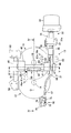
- FIG. 1 is an overall schematic view of a vehicle equipped with a multi-disc transmission.
- FIG. 2 is a view of the multi-disc transmission as viewed from the engine side.
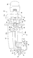
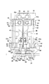
- FIG. 3 is a bottom view of FIG. 4 is a cross-sectional view taken along the line IV-IV in FIG. 5 is a cross-sectional view taken along the line VV in FIG.
- FIG. 6 is a diagram showing a disk.
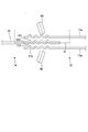
- FIG. 7 is a diagram illustrating a torque transmission unit.
- FIG. 8 is a diagram showing a disk overlap area when the disk is at the reference position.
- FIG. 1 is an overall schematic diagram of a vehicle including a multi-disc transmission according to an embodiment of the present invention.
- the vehicle 1 includes an engine 2 as a power source, a multi-disc transmission (hereinafter referred to as a transmission) 3, left and right drive shafts 4 and 5, and left and right drive wheels 6 and 7.
- a transmission multi-disc transmission
- left and right drive shafts 4 and 5 left and right drive wheels 6 and 7.
- the transmission 3 includes a transmission case 9, an input shaft 10, a primary disk 11, a secondary disk 12, a pressing mechanism 13, an output shaft 14, a dry start clutch 15, a reverse gear 16, and a reverse idler gear. 17, an output gear 18, a synchronization mechanism 19, a final gear 20, and a differential gear unit 21.
- the input shaft 10 and the output shaft 14 are arranged in parallel and are rotatably supported by the transmission case 9.
- FIG. 2 is a view of the transmission 3 as viewed from the engine 2 side.
- FIG. 3 is a bottom view of FIG. 4 is a cross-sectional view taken along the line IV-IV in FIG.
- a part of member is abbreviate
- the primary disk 11 is configured by arranging two circular disks 11 a in the axial direction of the input shaft 10 and attaching them to the input shaft 10, and rotates integrally with the input shaft 10.
- a spacer 22 is provided between the two disks 11 a, and the two disks 11 a are arranged at a predetermined interval in the axial direction of the input shaft 10 by the spacer 22.
- the primary disk 11 is arranged so that the outer peripheral end of the disk 11 a is close to the output shaft 14. The primary disk 11 rotates with the input shaft 10 in the direction of the arrow in FIG.
- the secondary disk 12 rotates together with the output shaft 14.
- the secondary disk 12 is arranged so that the outer peripheral end is close to the input shaft 10.
- the secondary disk 12 is a circular disk and is thicker in the axial direction of the output shaft 14 than the disk 11a of the primary disk 11.
- the convex portion 111 and the concave portion 112 are formed on the disk 11a, and the convex portion 121 and the concave portion 122 are formed on the secondary disk 12.
- the convex portions 111 and 121 and the concave portions 112 and 122 will be described in detail later.
- the disk 11a of the primary disk 11 is arranged on both sides with the secondary disk 12 in between.
- the primary disk 11 and the secondary disk 12 form a disk overlap region where a part of the disk overlaps between the input shaft 10 and the output shaft 14.
- a gap is formed between the disk 11a of the primary disk 11 and the secondary disk 12 in a state where the pressing force by the pressing mechanism 13 described in detail below does not act.
- the primary disk 11 and the secondary disk 12 are elastically deformed, and the convex portions 111 (121) and the concave portions 112 (112) are engaged, and the torque transmission portion. Is formed.
- the transmission 3 the transmission of rotation from the input shaft 10 to the output shaft 14 is realized by forming a torque transmission portion between the primary disk 11 and the secondary disk 12.
- the axis connection line O is a line that connects the axis of the input shaft 10 and the axis of the output shaft 14 and is orthogonal to the input shaft 10 and the output shaft 14. The torque transmission unit will be described in detail later.
- the pressing mechanism 13 includes a pair of pressing roller mechanisms 30, a pair of disk clamp mechanisms 31, a pressing force adjusting mechanism 32, and a first actuator 33.
- the first actuator 33 moves the pressing roller mechanism 30 along the axial connection line O.
- the first actuator 33 includes an electric motor 34, a ball screw mechanism 35, and a bracket 37.
- the ball screw mechanism 35 has one end connected to the rotating shaft of the electric motor 34 and rotates in the forward or reverse direction depending on the rotating direction of the rotating shaft of the electric motor 34.
- the ball screw mechanism 35 is extended in the direction of the axis connection line O.
- the bracket 37 moves along the axial direction of the ball screw mechanism 35, that is, the direction of the axis connection line O according to the rotation of the ball screw mechanism 35.
- the bracket 37 is formed with a tapered surface 37a on the surface on the engine 2 side, the distance from the ball screw mechanism 35 becomes shorter toward the electric motor 34 side.
- a push rod (not shown) that follows a tapered surface 37a like a so-called cam follower is reciprocated, and the release lever of the dry start clutch 15 is driven by the push rod. The clutch is engaged and released.
- the bracket 37 is connected to the second support portion 44 and the roller follower support block 48 of the pressing roller mechanism 30 through a first shaft 38 extending in the direction of the axis connection line O.
- the bracket 37 moves back and forth along the direction of the axis connection line O according to the rotation direction of the ball screw mechanism 35, and the pressing roller mechanism 30 moves to the bracket 37 and the first. It is integrated with the shaft 38 and moves back and forth along the direction of the axis connection line O.
- FIG. 5 is a VV cross-sectional view of FIG.
- the pressing roller mechanism 30 includes a pressing roller 40, a holding portion 41, a pressing roller shaft 42, a first support portion 43, a second support portion 44, a support block 46, and a first roller follower 47.
- the pair of pressing roller mechanisms 30 are disposed on both sides of the primary disk 11 and the secondary disk 12 and are attached to the guide block 49.
- the guide block 49 is slidably supported by two guide shafts 51 provided between the two guide shaft blocks 50 attached to the transmission case 9 and extending in the direction of the axis connection line O.
- the pressing roller mechanism 30 is slidably supported by the guide shaft 51 via the guide block 49, moves in the direction of the axis connection line O by the first actuator 33, and transmits torque to a position corresponding to the target gear ratio. Forming part.
- the pressing roller shaft 42 extends in a direction intersecting with the direction of the axis connection line O, one end portion 42 a is supported by the first support portion 43, and the other end portion 42 b is supported by the second support portion 44. Is done.
- the pressing roller shaft 42 has a spherical end portion 42 b supported by the second support portion 44.
- a holding portion 41 that supports the pressing roller 40 is attached to the pressing roller shaft 42 between the first support portion 43 and the second support portion 44.
- the first support portion 43 is rotatably supported by the guide block 49 via a rotation shaft 52 provided in parallel with the guide shaft 51.
- the first support portion 43 supports one end portion 42 a of the pressing roller shaft 42 via the needle bearing 53.
- the second support portion 44 supports the other end portion 42 b of the pressing roller shaft 42 via the support block 46 and the needle bearing 54.
- a bush 55 having a spherical tip 55a is provided between the second support portion 44 and the support block 46 in the axial direction of the input shaft 10, and a gap is provided between the second support portion 44 and the support block 46. Is formed.
- the gap in the axial direction of the input shaft 10 is positioned closer to the primary disk 11 than the bush 55, and the tip 55 a of the bush 55 contacts the support block 46.
- the second support portion 44 is connected to the end portion of the second shaft 56 that extends in the direction of the axis connection line O and the direction orthogonal to the axial direction of the input shaft 10 and to which the first roller follower 47 is attached.
- the second support portion 44 moves in the axial direction of the input shaft 10 by a pressing force applied to the first roller follower 47. According to the movement of the second support portion 44 in the axial direction of the input shaft 10, the first support portion 43 and the holding portion 41 that supports the pressing roller 40 rotate about the rotation shaft 52.
- the first support portion 43 is provided so as to form a gap between the needle bearing 53 and the pressing roller shaft 42 in the direction of the axis connection line O.
- the end portion 42 b of the pressing roller shaft 42 supported by the second support portion 44 has a spherical shape, and the end portion 42 b is in contact with the needle bearing 54. Accordingly, the pressing roller shaft 42 is supported by the first support portion 43 and the second support portion 44 so as to be rotatable and tiltable with respect to the direction of the axis connection line O.
- the holding portion 41 is provided between the first support portion 43 and the second support portion 44 and is attached to the pressing roller shaft 42.
- the holding portion 41 rotates and tilts integrally with the pressing roller shaft 42.
- the first shaft part 57 is fixed to the holding part 41.
- the pressing roller shaft 42 is in a direction perpendicular to the axial center connection line O when viewed from the axial direction of the input shaft 10, the first shaft portion 57 coincides with the axial center connection line O. Further, the first shaft portion 57 is provided so that the first shaft portion 57 inclines with respect to the disk surface in FIG.
- the pressing roller 40 is rotatably supported by the first shaft portion 57.
- the pressing roller 40 abuts on the disk 11a in the disk overlapping region and rotates around the first shaft portion 57.
- the pressing roller 40 elastically deforms the disks 11 and 12 to form a torque transmitting portion.
- the urging force of the springs 60 of the urging portions 45 a and 45 b acts on the pressing roller 40 via the holding portion 41.
- a second shaft 56 connected to the second support portion 44 is inserted into the inner peripheral hole 47a, and the front clamp arm 67 and the rear clamp arm 68 on the side of the disks 11, 12 are arranged. Rolls in contact with the side surfaces 67a and 68a.
- the end portion of the second shaft 56 opposite to the end portion connected to the second support portion 44 is inserted into a hole 48 a formed in the roller follower support block 48.
- the hole 48 a is an oval-shaped hole formed along the axial direction of the input shaft 10.
- the roller follower support block 48 supports the second shaft 56 slidably in the axial direction of the input shaft 10 along the hole 48a.
- the roller follower support block 48 is connected to the bracket 37 via a first shaft 38 extending in the direction of the axis connection line O, and moves in the direction of the axis connection line O according to the movement of the bracket 37.
- the disc clamp mechanism 31 includes an arm shaft 65, a front clamp arm 67, and a rear clamp arm 68.
- the arm shaft 65 is a columnar member that extends in a direction perpendicular to the axial connection line O and the input shaft 10.
- the arm shaft 65 is provided so as to be orthogonal to the input shaft 10 and to overlap the center of the primary disk 11 in the axial direction of the input shaft 10 as shown in FIG.
- the front clamp arm 67 is a plate-like member having a substantially L shape as shown in FIG.
- the front clamp arm 67 is rotatably supported on the arm shaft 65 on one end side.
- an engaging portion 72 of a pressing force adjusting mechanism 32 described later is formed.
- the front clamp arm 67 is in contact with the first roller follower 47 at the side surface 67 a (the surface forming the thickness of the plate member) on the side of the disks 11 and 12.
- the rear clamp arm 68 is a plate-like member having a substantially L shape as shown in FIG.
- the rear clamp arm 68 is rotatably supported on the arm shaft 65 on one end side.
- the other end of the rear clamp arm 68 is connected to a case 70 of a pressing force adjusting mechanism 32 described later.
- the side surface 68 a (the surface forming the thickness of the plate-like member) of the rear clamp arm 68 contacts the first roller follower 47.
- the front clamp arm 67 and the rear clamp arm 68 are rotated about the arm shaft 65 by the pressing force generated by the pressing force adjusting mechanism 32, and the pressing force is applied to the holding portion 41 by sandwiching the pair of pressing roller mechanisms 30.
- a pressing force is applied from the pressing roller 40 to the primary disk 11 and the secondary disk 12.
- the pressing force adjusting mechanism 32 includes a case 70, a second shaft portion 71, an engaging portion 72, a rotating portion 73, a compression spring 74, and a second actuator (not shown). Is provided.
- the case 70 is connected to the end of the rear clamp arm 68.
- the case 70 accommodates a part of the rotating part 73, and the second shaft part 71 is attached thereto.
- the second shaft portion 71 is a columnar member parallel to the arm shaft 65 and supports the rotating portion 73 in a rotatable manner.
- the engaging portion 72 is formed at the end portion of the front clamp arm 67, and extends from the end portion toward the rear clamp arm 68, and the second shaft portion extends from the end portion of the connecting portion 75 on the rear clamp arm 68 side. And a curved surface portion 76 extending so as to surround 71.
- the curved surface portion 76 has an arc-shaped outer peripheral wall with the second shaft portion 71 as the center.
- the second roller follower 79 of the rotating portion 73 comes into contact with the outer peripheral wall of the curved surface portion 76 and rolls.
- the rotating unit 73 includes a rotating body 77, a rotation transmitting block 78, and a second roller follower 79.
- the rotating body 77 includes a first body 80 and a second body 81.
- the first body 80 is a substantially U-shaped member extending so as to sandwich the second shaft portion 71.
- the first body 80 abuts on the outer peripheral wall of the second shaft portion 71 and is supported by the second shaft portion 71 so as to be rotatable and slidable.
- the first body 80 includes a stopper 82 that supports one end of the compression spring 74 at the end on the open side.
- the rotation transmission block 78 is supported by the second shaft portion 71 so as to be rotatable through the second shaft portion 71.
- the rotation transmission block 78 supports the end of the compression spring 74 opposite to the end supported by the stopper 82.
- the first body 80 and the second body 81 are joined, and the second roller follower 79 is attached to the second body 81.
- the rotating body 77 is always urged in the direction from the second shaft portion 71 toward the stopper 82 by the restoring force of the compression spring 74.
- the second body 81 located on the opposite side to the compression spring 74 with respect to the second shaft portion 71 abuts on the rotation transmission block 78, and the rotation body 77 moves from the second shaft portion 71 toward the compression spring 74. Is regulated.
- the second roller follower 79 rolls in contact with the arc-shaped outer peripheral wall of the curved surface portion 76.
- the second roller follower 79 rotates the second shaft portion 71 integrally with the rotary body 77 by the second actuator, and is always biased toward the second shaft portion 71 by the compression spring 74.
- the pressing force adjusting mechanism 32 rotates the second roller follower 79 about the second shaft portion 71, thereby causing the compression spring 74 to urge the second roller follower 79 toward the second shaft portion 71. Change direction. Thereby, the force which pushes the front clamp arm 67 to the rear clamp arm 68 side, ie, the pressing force which clamps a pair of pressing roller mechanism 30, is changed.
- FIG. 6 shows the disk 11a.
- FIG. 7 is a diagram illustrating a torque transmission unit.
- the convex portion 111 and the concave portion 112 are formed on the disk 11a, and the convex portion 121 and the concave portion 122 are formed on the secondary disk 12.
- the convex portions 111 and the concave portions 112 of the disc 11a are alternately formed in the disc circumferential direction on the circumference that is concentric with the disc 11a. Since the diameter of the circumference is set so that the convex portion 111 and the concave portion 112 are formed at a position corresponding to the gear ratio of the transmission 3, the convex portion 111 and the concave portion 112 correspond to the number of shift stages. Are formed on a plurality of circumferences.
- the convex portions 111 formed on a plurality of circumferences are provided in series in the disk radial direction at one place, as indicated by arrows in FIG. Note that the convex portion 111 and the concave portion 112 are formed integrally with each other because the disk 11a is a plate material.
- a convex part 121 and a concave part 122 are formed.
- the primary disk 11 and the secondary disk 12 are elastically deformed, and the convex part 111 of the disk 11a and the concave part 122 of the secondary disk 12 are engaged.
- the concave portion 112 and the convex portion 121 of the secondary disk 12 are engaged to form a torque transmission portion.
- the engaging portion between the convex portion 111 (121) and the concave portion 122 (112) is in an angled state, so that the pressing roller 40 is driven by the driving force of the primary disk 11.
- a normal force against the pressing force that is, a force for separating the disks 11 and 12 is generated.
- the vertical drag decreases as the contact angle of the engaging portion increases.
- the convex portion 111 (121) and the concave portion 122 (112) are formed so that the contact angle of the engaging portion is 45 degrees, the normal force is equal to the driving force, This is about 10% of the pressing force in a multi-disc transmission that transmits torque by frictional force.
- torque can be transmitted unless the engagement between the convex portion 111 (121) and the concave portion 122 (112) is disengaged, so that the engagement portion between the convex portion 111 (121) and the concave portion 122 (112)
- the pressing force of the pressing roller 40 can be reduced according to the vertical drag determined by the contact angle and the driving force of the primary disk 11a.
- the pressing mechanism 13 and the pressing roller 40 can be reduced in size, it is possible to move the pressing roller 40 closer to the input shaft 10 and the output shaft 14 and to increase the width of the gear ratio. Further, the transmission 3 can be reduced in size and durability can be improved.
- the protrusions 111 formed on the plurality of circumferences of the disk 11a are provided in series in the disk radial direction at one place, and the protrusions 121 formed on the secondary disk 12 are also Similar to the disk 11a, the disk 11a is provided in series in the disk radial direction at one place.
- the convex portions 111 and 121 provided in series are viewed from the opposite side of the disks 11 and 12, the concave portions 112 and 122 are provided in series.
- the discs 11 and 12 are arranged so that the convex portions 111 and 121 provided in series do not face each other, and the convex portions 111 and 121 provided in series are arranged in the direction of the axis connection line O. It is assembled to the transmission 3 with the aligned position as a reference position.
- the convex portions 111 (121) and the concave portions 122 ( 112) and the convex portion 111 and the convex portion 121 do not interfere with each other, and the concave portion 112 and the concave portion 122 face each other and the primary disk 11 does not idle. Therefore, the speed can be changed while the pressing roller 40 is pressed against the disks 11 and 12, and a multi-stage speed change in which torque transmission is not interrupted is possible.
- the contact angle of the engaging portion between the convex portion 111 (121) and the concave portion 112 (122) can be reduced according to the vertical resistance against the pressing force of the pressing roller 40 determined by the driving force of the primary disk 11.
- the convex portions 111 and 121 formed on the plurality of circumferences of the disk 11a and the secondary disk 12 are provided in series in the radial direction of the disc at one place, the convex portions 111 and 121 provided in series are provided.
- the convex portion 111 (121) and the concave portion 122 (112) are engaged and the convex portion 111 is engaged even if the pressing roller 40 is pressed against the disks 11 and 12 to change speed.
- the convex portion 121 face each other and do not interfere with each other, and the concave portion 112 and the concave portion 122 face each other and the primary disk 11 does not idle. Therefore, the speed can be changed while the pressing roller 40 is pressed against the disks 11 and 12, and a multi-stage speed change in which torque transmission is not interrupted is possible.
- the configuration includes two disks 11a and one secondary disk 12.
- a configuration including one disk 11a and one secondary disk 12 may be used.
- the convex parts 111 and 121 and the recessed parts 112 and 122 of the disks 11 and 12 are formed so that the contact angle of an engaging part may be 45 degree
- the convex portions 111 and 121 and the concave portions 112 and 122 may be formed.
Landscapes
- Engineering & Computer Science (AREA)
- General Engineering & Computer Science (AREA)
- Mechanical Engineering (AREA)
- Friction Gearing (AREA)
Abstract
マルチディスク変速機は、入力軸と、出力軸と、プライマリディスクと、セカンダリディスクと、一対の押付ローラと、変速アクチュエータと、押付機構と、を備え、プライマリディスクは、ディスク円周方向に交互に形成された凸部と凹部とを、プライマリディスクと同芯となる複数の円周上に有し、セカンダリディスクは、ディスク円周方向に交互に形成された凸部と凹部とを、セカンダリディスクと同芯となる複数の円周上に有し、一対の押付ローラを、プライマリディスク及びセカンダリディスクに押し付けると、プライマリディスク及びセカンダリディスクの一方に形成された凸部と、他方に形成された凹部とが係合する。
Description
本発明は、マルチディスク変速機に関する。
JP2010-53995Aには、入力軸に設けられたプライマリディスクと出力軸に設けられたセカンダリディスクとを部分的に重ね合わせてディスク重合領域を設け、この領域で両ディスクを一対の押付ローラで挟んで接触させることで、入力軸の回転を出力軸に伝達するマルチディスク変速機が開示されている。
マルチディスク変速機においては、一対の押付ローラが両ディスクを挟む位置を変更することによって変速が実現される。すなわち、両ディスクを挟む位置を、入力軸に近づければ変速比がLow側(変速比大側)に変化し、出力軸に近づければ変速比がHigh側(変速比小側)に変化する。
マルチディスク変速機では、押付ローラがプライマリディスクとセカンダリディスクとを挟んで接触させ、接触部に発生する摩擦力によりトルクを伝達するので、押付ローラの押付力が不足すると接触部でスリップが発生してトルク伝達効率が低下するという問題がある。そこで、押付力を大きくしてスリップの発生を防止することが考えられるが、押付力を大きくすると、それに伴って変速機が大型化するという問題がある。
本発明は、このような技術的課題に鑑みてなされたもので、押付力を大きくすることなくスリップの発生を防止することを目的とする。
本発明のある態様によれば、マルチディスク変速機であって、動力源からの回転が入力される入力軸と、前記入力軸に対して平行に配置される出力軸と、前記入力軸に設けられるプライマリディスクと、前記出力軸に設けられ、前記プライマリディスクと重なり合うディスク重合領域を有するセカンダリディスクと、前記ディスク重合領域において前記プライマリディスク及び前記セカンダリディスクを挟んで両側に配置される一対の押付ローラと、前記一対の押付ローラを、前記入力軸と前記出力軸との間で移動させる変速アクチュエータと、前記一対の押付ローラを、前記プライマリディスク及び前記セカンダリディスクに押し付ける押付機構と、を備え、前記プライマリディスクは、ディスク円周方向に交互に形成された凸部と凹部とを、前記プライマリディスクと同芯となる複数の円周上に有し、前記セカンダリディスクは、ディスク円周方向に交互に形成された凸部と凹部とを、前記セカンダリディスクと同芯となる複数の円周上に有し、前記一対の押付ローラを、前記プライマリディスク及び前記セカンダリディスクに押し付けると、前記プライマリディスク及び前記セカンダリディスクの一方に形成された前記凸部と、他方に形成された前記凹部とが係合するマルチディスク変速機が提供される。
以下、添付図面を参照しながら本発明の実施形態について説明する。
図1は、本発明の実施形態に係るマルチディスク変速機を備えた車両の全体概略図である。
車両1は、動力源としてのエンジン2と、マルチディスク変速機(以下、変速機と言う。)3と、左右の駆動軸4、5と、左右の駆動輪6、7とを備える。
変速機3は、変速機ケース9と、入力軸10と、プライマリディスク11と、セカンダリディスク12と、押付機構13と、出力軸14と、乾式発進クラッチ15と、リバースギア16と、リバースアイドラギア17と、出力ギア18と、シンクロ機構19と、ファイナルギア20と、デファレンシャルギアユニット21とを備える。
入力軸10と出力軸14とは平行に配置され、変速機ケース9によって回転可能に支持される。
図2は変速機3をエンジン2側から見た図である。図3は図2の下面図である。図4は図2のIV-IV断面図である。なお、図2以降の図面については説明のため部材の一部を省略している。
プライマリディスク11は、2枚の円形のディスク11aを入力軸10の軸方向に並べて入力軸10に取り付けて構成され、入力軸10と一体となって回転する。2枚のディスク11aの間にはスペーサ22が設けられ、2枚のディスク11aは、スペーサ22によって入力軸10の軸方向に所定の間隔を設けて配置される。プライマリディスク11は、ディスク11aの外周端が出力軸14に近接するように配置される。プライマリディスク11は入力軸10とともに図2の矢印方向に回転する。
セカンダリディスク12は、出力軸14と一体となって回転する。セカンダリディスク12は、外周端が入力軸10に近接するように配置される。
セカンダリディスク12は、円形のディスクであり、プライマリディスク11のディスク11aよりも出力軸14の軸方向における厚さが厚い。
また、ディスク11aには、凸部111と凹部112とが形成され、セカンダリディスク12には、凸部121と凹部122とが形成される。凸部111、121と凹部112、122とについては後で詳しく述べる。
プライマリディスク11のディスク11aは、セカンダリディスク12を挟んで両側に配置される。プライマリディスク11とセカンダリディスク12とは、入力軸10と出力軸14との間で、ディスクの一部が重なり合うディスク重合領域を形成する。
ディスク重合領域において、プライマリディスク11のディスク11aとセカンダリディスク12との間には、以下に詳述する押付機構13による押付力が作用しない状態では、隙間が形成される。
これに対し、押付機構13による押付力が作用する状況では、プライマリディスク11とセカンダリディスク12とが弾性変形して凸部111(121)と凹部112(112)とが係合し、トルク伝達部が形成される。変速機3においては、プライマリディスク11とセカンダリディスク12との間にトルク伝達部が形成されることで、入力軸10から出力軸14への回転の伝達が実現される。また、軸心連結線Oは、入力軸10の軸心と出力軸14の軸心とを結び、入力軸10と出力軸14とに直交する線である。なお、トルク伝達部については後で詳しく述べる。
押付機構13は、一対の押付ローラ機構30と、一対のディスククランプ機構31と、押付力調整機構32と、第1アクチュエータ33とを備える。
第1アクチュエータ33は、押付ローラ機構30を軸心連結線Oに沿って移動させる。
第1アクチュエータ33は、電動モータ34と、ボールスクリュー機構35と、ブラケット37とを備える。
ボールスクリュー機構35は、一方の端部が電動モータ34の回転軸に連結され、電動モータ34の回転軸の回転方向に応じて正方向または逆方向に回転する。ボールスクリュー機構35は軸心連結線O方向に延設される。
ブラケット37は、ボールスクリュー機構35が回転すると、ボールスクリュー機構35の回転に応じてボールスクリュー機構35の軸方向、つまり軸心連結線O方向に沿って移動する。ブラケット37には、電動モータ34側となるにつれてボールスクリュー機構35からの距離が短くなるテーパ面37aがエンジン2側の面に形成される。ブラケット37が電動モータ34によって往復動されると、テーパ面37aに所謂カムフォロワーのように追随するプッシュロッド(図示せず)が往復動され、プッシュロッドによって乾式発進クラッチ15のレリーズレバーが駆動されてクラッチの締結及び解放がなされる。
ブラケット37は、軸心連結線O方向に延設される第1シャフト38を介して、押付ローラ機構30の第2支持部44、ローラフォロアサポートブロック48に連結する。電動モータ34によってボールスクリュー機構35が回転されると、ブラケット37はボールスクリュー機構35の回転方向に応じて軸心連結線O方向に沿って前後進し、押付ローラ機構30がブラケット37および第1シャフト38と一体となって軸心連結線O方向に沿って前後進する。
図5は、図2のV-V断面図である。
押付ローラ機構30は、押付ローラ40と、保持部41と、押付ローラシャフト42と、第1支持部43と、第2支持部44と、サポートブロック46と、第1ローラフォロア47とを備える。
一対の押付ローラ機構30は、プライマリディスク11及びセカンダリディスク12を挟んで両側に配置され、ガイドブロック49に取り付けられている。ガイドブロック49は、変速機ケース9に取り付けられる2つのガイドシャフトブロック50の間に設けられて軸心連結線O方向に延設される2本のガイドシャフト51に摺動可能に支持される。つまり、押付ローラ機構30は、ガイドブロック49を介してガイドシャフト51に摺動可能に支持され、第1アクチュエータ33により軸心連結線O方向に移動し、目標変速比に対応する位置にトルク伝達部を形成する。
押付ローラシャフト42は、軸心連結線O方向に交差する方向に延設され、一方の端部42aを第1支持部43によって支持され、もう一方の端部42bを第2支持部44によって支持される。押付ローラシャフト42は、第2支持部44によって支持される端部42bが球形状となっている。押付ローラシャフト42には第1支持部43と第2支持部44との間に押付ローラ40を支持する保持部41が取り付けられる。
第1支持部43は、ガイドシャフト51と平行に設けた回動軸52を介してガイドブロック49に回動可能に支持されている。第1支持部43は、押付ローラシャフト42の一方の端部42aをニードルベアリング53を介して支持する。
第2支持部44は、押付ローラシャフト42のもう一方の端部42bをサポートブロック46およびニードルベアリング54を介して支持する。入力軸10の軸方向における第2支持部44とサポートブロック46との間には、球形状の先端部55aを有するブッシュ55が設けられ、第2支持部44とサポートブロック46との間に隙間が形成される。入力軸10の軸方向において隙間はブッシュ55よりもプライマリディスク11側に位置し、ブッシュ55の先端部55aがサポートブロック46に当接する。第2支持部44には軸心連結線O方向、および入力軸10の軸方向に直交する方向に延び、第1ローラフォロア47が取り付けられた第2シャフト56の端部が連結する。第2支持部44は第1ローラフォロア47にかかる押付力によって入力軸10の軸方向に移動する。第2支持部44の入力軸10の軸方向への移動に応じて、第1支持部43、および押付ローラ40を支持する保持部41は、回動軸52を中心として回動する。
第1支持部43は、軸心連結線O方向において、ニードルベアリング53と押付ローラシャフト42との間に隙間を形成するように設けられる。第2支持部44に支持される押付ローラシャフト42の端部42bは球形状となっており、この端部42bがニードルベアリング54と当接している。これにより、押付ローラシャフト42は、回動、かつ、軸心連結線O方向に対して傾動可能に第1支持部43および第2支持部44に支持される。
保持部41は、第1支持部43と第2支持部44との間に設けられ、押付ローラシャフト42に取り付けられる。保持部41は、押付ローラシャフト42と一体となって回動、および傾動する。
保持部41には第1軸部57が固定される。入力軸10の軸方向から見た場合に、押付ローラシャフト42が軸心連絡線Oに対して直角な方向にある場合には、第1軸部57は軸心連絡線Oと一致する。また、第1軸部57は、図4において第1軸部57がディスク面に対して傾斜するように設けられる。
押付ローラ40は、第1軸部57に回転可能に支持される。
押付ローラ40は、ディスク重合領域において、ディスク11aと当接し、第1軸部57を中心に回転する。押付ローラ40は、第1ローラフォロア47を介して伝達される押付力が大きくなると、ディスク11、12を弾性変形させて、トルク伝達部を形成する。
押付ローラ40には、保持部41を介して付勢部45a、45bのバネ60の付勢力が作用する。
第1ローラフォロア47は、図5に示すように第2支持部44と連結する第2シャフト56が内周孔47aに挿入され、フロントクランプアーム67およびリアクランプアーム68のディスク11、12側の側面67a、68aに当接して転動する。
第2支持部44に連結する端部とは反対側の第2シャフト56の端部は、ローラフォロアサポートブロック48に形成された孔48aに挿入される。孔48aは、入力軸10の軸方向に沿って形成されるオーバル形状の孔である。ローラフォロアサポートブロック48は孔48aに沿って第2シャフト56を入力軸10の軸方向に摺動可能に支持する。また、ローラフォロアサポートブロック48は、軸心連結線O方向に延びる第1シャフト38を介してブラケット37に連結しており、ブラケット37の移動に応じて軸心連結線O方向に移動する。
ディスククランプ機構31は、アームシャフト65、フロントクランプアーム67およびリアクランプアーム68を備える。
アームシャフト65は、軸心連結線O、および入力軸10に対して直角な方向に延びる円柱状の部材である。アームシャフト65は、入力軸10と直交し、かつ図5に示すように入力軸10の軸方向におけるプライマリディスク11の中心と重なるように設けられる。
フロントクランプアーム67は、図3に示すように略L字状となる板状部材である。フロントクランプアーム67は一方の端部側でアームシャフト65に回動可能に支持されている。フロントクランプアーム67のもう一方の端部は、後述する押付力調整機構32の係合部72が形成されている。フロントクランプアーム67は、図5に示すようにディスク11、12側の側面67a(板状部材の厚みを形成する面)が第1ローラフォロア47に当接する。
リアクランプアーム68は、図3に示すように略L字状となる板状部材である。リアクランプアーム68は一方の端部側でアームシャフト65に回動可能に支持されている。リアクランプアーム68のもう一方の端部は、後述する押付力調整機構32のケース70に連結する。リアクランプアーム68は、図5に示すようにディスク11、12側の側面68a(板状部材の厚みを形成する面)が第1ローラフォロア47に当接する。
フロントクランプアーム67およびリアクランプアーム68は、押付力調整機構32によって発生する押付力によってアームシャフト65を支点として回動し、一対の押付ローラ機構30を挟持することで保持部41に押付力を作用させ、押付ローラ40からプライマリディスク11およびセカンダリディスク12に押付力を作用させる。
押付力調整機構32は、図3に示すようにケース70と、第2軸部71と、係合部72と、回動部73と、圧縮バネ74と、第2アクチュエータ(図示せず)とを備える。
ケース70は、リアクランプアーム68の端部に連結する。ケース70は回動部73の一部を収容し、第2軸部71が取り付けられる。
第2軸部71は、アームシャフト65と平行な円柱状の部材であり、回動部73を回動可能に支持する。
係合部72は、フロントクランプアーム67の端部に形成され、同端部からリアクランプアーム68側に延びる連結部75と、連結部75のリアクランプアーム68側の端部から第2軸部71を囲繞するように延びる曲面部76とを備える。曲面部76は、第2軸部71を中心とした円弧状の外周壁を有する。曲面部76の外周壁には、回動部73の第2ローラフォロア79が接触して転動する。
回動部73は、回転ボディ77と、回転伝達ブロック78と、第2ローラフォロア79とを備える。回転ボディ77は、第1ボディ80と、第2ボディ81とを備える。
第1ボディ80は、第2軸部71を挟むように延びた略U字状の部材である。第1ボディ80は、第2軸部71の外周壁に当接し、第2軸部71によって回動可能、且つ摺動可能に支持される。第1ボディ80は、開放側の端部に圧縮バネ74の一方の端部を支持するストッパー82を備える。
回転伝達ブロック78は、第2軸部71が貫通し、第2軸部71によって回動可能に支持される。回転伝達ブロック78は、圧縮バネ74のストッパー82によって支持される端部とは反対側の端部を支持する。
第1ボディ80と第2ボディ81とは接合されており、第2ボディ81には、第2ローラフォロア79が取り付けられる。
回転ボディ77は、圧縮バネ74の復元力によって、常に第2軸部71からストッパー82に向かう向きに付勢されている。しかし、第2軸部71に対して圧縮バネ74とは反対側に位置する第2ボディ81が回転伝達ブロック78に当接し、第2軸部71から圧縮バネ74方向への回転ボディ77の移動は規制される。
第2ローラフォロア79は曲面部76の円弧状の外周壁に当接して転動する。第2ローラフォロア79は、第2アクチュエータによって第2軸部71を回転ボディ77と一体となって回動し、圧縮バネ74によって常に第2軸部71に向けて付勢される。
押付力調整機構32は、第2ローラフォロア79を第2軸部71を中心に回動させることで、圧縮バネ74によって第2ローラフォロア79を第2軸部71に向けて付勢する力の方向を変更する。これにより、フロントクランプアーム67をリアクランプアーム68側へ押す力、すなわち一対の押付ローラ機構30を挟持する押付力を変更する。
次に、トルク伝達部について説明する。
図6は、ディスク11aを示す図である。図7はトルク伝達部を示す図である。
上記のように、ディスク11aには、凸部111と凹部112とが形成され、セカンダリディスク12には、凸部121と凹部122とが形成される。
ディスク11aの凸部111と凹部112とは、ディスク11aと同芯となる円周上に、ディスク円周方向に交互に形成される。円周の径は、変速機3の変速比に対応する位置に凸部111と凹部112とが形成されるように設定されるので、凸部111と凹部112とは、変速段の数に応じて複数の円周上に形成される。
また、複数の円周上に形成される凸部111は、図6の矢印で示すように、1か所においてディスク径方向に直列に設けられる。なお、凸部111と凹部112とは、ディスク11aが板材であることから表裏一体に形成される。
セカンダリディスク12についても、ディスク11aと同様に、凸部121と凹部122が形成される。
押付機構13による押付力が作用する状況では、プライマリディスク11とセカンダリディスク12とが弾性変形して、ディスク11aの凸部111とセカンダリディスク12の凹部122とが係合し、また、ディスク11aの凹部112とセカンダリディスク12の凸部121とが係合し、トルク伝達部を形成する。
このように、凸部111(121)と凹部122(112)とが係合した状態では、プライマリディスク11とセカンダリディスク12との間でスリップが発生することがないので、トルク伝達効率が低下することがない。
また、図7に示すように、凸部111(121)と凹部122(112)との係合部は、角度がついた状態で接触するので、プライマリディスク11の駆動力により、押付ローラ40の押付力に対する垂直抗力、すなわち、ディスク11、12を離間させる力が発生する。
しかしながら、垂直抗力は係合部の接触角度が大きいほど小さくなる。例えば、本実施形態では、係合部の接触角度が45度となるように凸部111(121)と凹部122(112)とが形成されるので、垂直抗力は駆動力と等しくなり、これは、摩擦力によりトルクを伝達するマルチディスク変速機における押付力の約1割である。
本実施形態においては、凸部111(121)と凹部122(112)との係合が外れなければトルクを伝達できるので、凸部111(121)と凹部122(112)との係合部の接触角度と、プライマリディスク11aの駆動力とにより定まる垂直抗力に応じて、押付ローラ40の押付力を小さくできる。
これにより、押付機構13や押付ローラ40を小型化できるので、押付ローラ40をより入力軸10、出力軸14の近くまで移動させることが可能となり、変速比の幅を拡大できる。また、変速機3の小型化や耐久性の向上も図ることができる。
また、上記のように、ディスク11aの複数の円周上に形成される凸部111は、一か所においてディスク径方向に直列に設けられ、セカンダリディスク12に形成される凸部121についても、ディスク11aと同様に、一か所においてディスク径方向に直列に設けられる。ここで、直列に設けられた凸部111、121を、ディスク11、12の反対側から見ると、凹部112、122が直列に設けられていることになる。
ディスク11、12は、図8に示すように、直列に設けられた凸部111、121が対向しない向きで、また、直列に設けられた凸部111、121が軸心連結線Oの方向に揃う位置を基準位置として、変速機3に組付けられる。
ディスク11、12が基準位置であるときは、押付機構13による押付力を作用させたまま押付ローラ40を目標変速比に対応する位置に移動させても、凸部111(121)と凹部122(112)とが係合し、凸部111と凸部121とが対向して干渉することがなく、また、凹部112と凹部122とが対向してプライマリディスク11が空回りすることがない。したがって、押付ローラ40をディスク11、12に押付けたまま変速することができ、トルク伝達が途切れない多段変速が可能となる。
なお、ディスク11a、セカンダリディスク12の円周上の凸部111、121と凹部112、122との数は、ディスク11aとセカンダリディスク12とで変速比毎に同数が設けられる。したがって、ディスク11、12が回転すると、一回転に一度、直列に設けられた凸部111、121が軸心連結線Oの方向に揃うので、このタイミングで変速が行われる。
上記態様によれば、凸部111(121)と凹部122(112)とが係合することでプライマリディスク11からセカンダリディスク12へトルクが伝達されるので、プライマリディスク11とセカンダリディスク12との間でスリップが発生することがなく、変速機のトルク伝達効率が低下しない。
また、凸部111(121)と凹部122(112)との係合が外れなければトルクを伝達できるので、凸部111(121)と凹部112(122)との係合部の接触角度と、プライマリディスク11の駆動力とにより定まる押付ローラ40の押付力に対する垂直抗力に応じて、押付ローラ40の押付力を小さくできる。
また、ディスク11a、セカンダリディスク12の複数の円周上に形成される凸部111、121は、一か所においてディスク径方向に直列に設けられるので、直列に設けられた凸部111、121が軸心連結線Oの方向に揃うタイミングでは、押付ローラ40をディスク11、12に押付けたまま変速しても、凸部111(121)と凹部122(112)とが係合し、凸部111と凸部121とが対向して干渉することがなく、また、凹部112と凹部122とが対向してプライマリディスク11が空回りすることがない。したがって、押付ローラ40をディスク11、12に押付けたまま変速することができ、トルク伝達が途切れない多段変速が可能となる。
以上、本発明の実施形態について説明したが、上記実施形態は本発明の適用例の一つを示したものに過ぎず、本発明の技術的範囲を上記実施形態の具体的構成に限定する趣旨ではない。
上記実施形態では、2枚のディスク11aと1枚のセカンダリディスク12を備える構成としているが、例えば、ディスク11aとセカンダリディスク12を1枚ずつ備える構成としてもよい。
また、上記実施形態では、係合部の接触角度が45度となるようにディスク11、12の凸部111、121と凹部112、122とが形成されているが、凸部111(121)と凹部122(112)との係合が外れない押付力を確保できる範囲内であれば、例えば、ディスク11、12の成形性を考慮して、係合部の接触角度が45度より小さくなるように凸部111、121と凹部112、122とを形成してもよい。
本願は2013年2月5日に日本国特許庁に出願された特願2013-020706に基づく優先権を主張し、この出願の全ての内容は参照により本明細書に組み込まれる。
Claims (2)
- マルチディスク変速機であって、
動力源からの回転が入力される入力軸と、
前記入力軸に対して平行に配置される出力軸と、
前記入力軸に設けられるプライマリディスクと、
前記出力軸に設けられ、前記プライマリディスクと重なり合うディスク重合領域を有するセカンダリディスクと、
前記ディスク重合領域において前記プライマリディスク及び前記セカンダリディスクを挟んで両側に配置される一対の押付ローラと、
前記一対の押付ローラを、前記入力軸と前記出力軸との間で移動させる変速アクチュエータと、
前記一対の押付ローラを、前記プライマリディスク及び前記セカンダリディスクに押し付ける押付機構と、を備え、
前記プライマリディスクは、ディスク円周方向に交互に形成された凸部と凹部とを、前記プライマリディスクと同芯となる複数の円周上に有し、
前記セカンダリディスクは、ディスク円周方向に交互に形成された凸部と凹部とを、前記セカンダリディスクと同芯となる複数の円周上に有し、
前記一対の押付ローラを、前記プライマリディスク及び前記セカンダリディスクに押し付けると、前記プライマリディスク及び前記セカンダリディスクの一方に形成された前記凸部と、他方に形成された前記凹部とが係合するマルチディスク変速機。 - 請求項1に記載のマルチディスク変速機であって、
前記プライマリディスク及び前記セカンダリディスクの前記複数の円周上の前記凸部と前記凹部とのいずれかは、前記円周上の少なくとも一か所で、ディスク径方向に直列に設けられるマルチディスク変速機。
Priority Applications (1)
| Application Number | Priority Date | Filing Date | Title |
|---|---|---|---|
| JP2014560647A JPWO2014122848A1 (ja) | 2013-02-05 | 2013-12-09 | マルチディスク変速機 |
Applications Claiming Priority (2)
| Application Number | Priority Date | Filing Date | Title |
|---|---|---|---|
| JP2013020706 | 2013-02-05 | ||
| JP2013-020706 | 2013-02-05 |
Publications (1)
| Publication Number | Publication Date |
|---|---|
| WO2014122848A1 true WO2014122848A1 (ja) | 2014-08-14 |
Family
ID=51299452
Family Applications (1)
| Application Number | Title | Priority Date | Filing Date |
|---|---|---|---|
| PCT/JP2013/082965 Ceased WO2014122848A1 (ja) | 2013-02-05 | 2013-12-09 | マルチディスク変速機 |
Country Status (2)
| Country | Link |
|---|---|
| JP (1) | JPWO2014122848A1 (ja) |
| WO (1) | WO2014122848A1 (ja) |
Citations (2)
| Publication number | Priority date | Publication date | Assignee | Title |
|---|---|---|---|---|
| JPH05141494A (ja) * | 1991-11-12 | 1993-06-08 | Manyou:Kk | 変速装置 |
| JP2010053995A (ja) * | 2008-08-29 | 2010-03-11 | Jatco Ltd | 変速機 |
-
2013
- 2013-12-09 JP JP2014560647A patent/JPWO2014122848A1/ja active Pending
- 2013-12-09 WO PCT/JP2013/082965 patent/WO2014122848A1/ja not_active Ceased
Patent Citations (2)
| Publication number | Priority date | Publication date | Assignee | Title |
|---|---|---|---|---|
| JPH05141494A (ja) * | 1991-11-12 | 1993-06-08 | Manyou:Kk | 変速装置 |
| JP2010053995A (ja) * | 2008-08-29 | 2010-03-11 | Jatco Ltd | 変速機 |
Also Published As
| Publication number | Publication date |
|---|---|
| JPWO2014122848A1 (ja) | 2017-01-26 |
Similar Documents
| Publication | Publication Date | Title |
|---|---|---|
| JP6890150B2 (ja) | 動力伝達装置 | |
| JP6961000B2 (ja) | クラッチ及び車両の動力伝達構造 | |
| JP5272089B1 (ja) | モータサイクル用クラッチ装置 | |
| JP6961427B2 (ja) | 動力伝達装置 | |
| WO2013100130A1 (ja) | 動力伝達装置 | |
| JP6617051B2 (ja) | クラッチ装置 | |
| JP2009281570A (ja) | デュアルクラッチの操作装置 | |
| WO2014112163A1 (ja) | マルチディスク変速機 | |
| JP2022145785A (ja) | 動力伝達装置 | |
| JP6617031B2 (ja) | クラッチ装置 | |
| WO2014122848A1 (ja) | マルチディスク変速機 | |
| JP5926407B2 (ja) | マルチディスク変速機 | |
| JP6006862B2 (ja) | マルチディスク変速機 | |
| JP2014222084A (ja) | マルチディスク変速機 | |
| JP5768102B2 (ja) | マルチディスク変速機 | |
| JP5926442B2 (ja) | マルチディスク変速機 | |
| JP5934157B2 (ja) | マルチディスク変速機 | |
| JP5795786B2 (ja) | マルチディスク変速機 | |
| JP5905639B2 (ja) | マルチディスク変速機 | |
| JP5740444B2 (ja) | マルチディスク変速機 | |
| JP5683662B1 (ja) | マルチディスク変速機 | |
| JP2015064033A (ja) | マルチディスク変速機 | |
| WO2013011575A1 (ja) | 変速機 | |
| JP2008101663A (ja) | デファレンシャル装置 | |
| JP2017044247A (ja) | デファレンシャル装置 |
Legal Events
| Date | Code | Title | Description |
|---|---|---|---|
| 121 | Ep: the epo has been informed by wipo that ep was designated in this application |
Ref document number: 13874797 Country of ref document: EP Kind code of ref document: A1 |
|
| ENP | Entry into the national phase |
Ref document number: 2014560647 Country of ref document: JP Kind code of ref document: A |
|
| NENP | Non-entry into the national phase |
Ref country code: DE |
|
| 122 | Ep: pct application non-entry in european phase |
Ref document number: 13874797 Country of ref document: EP Kind code of ref document: A1 |